CN106688155B - System and method for switching electrical system to standby power in a utility power outage - Google Patents
System and method for switching electrical system to standby power in a utility power outageDownload PDFInfo
- Publication number
- CN106688155B CN106688155BCN201580046802.9ACN201580046802ACN106688155BCN 106688155 BCN106688155 BCN 106688155BCN 201580046802 ACN201580046802 ACN 201580046802ACN 106688155 BCN106688155 BCN 106688155B
- Authority
- CN
- China
- Prior art keywords
- branch circuit
- circuit breaker
- generation source
- circuit breakers
- power generation
- Prior art date
- Legal status (The legal status is an assumption and is not a legal conclusion. Google has not performed a legal analysis and makes no representation as to the accuracy of the status listed.)
- Active
Links
Images


Classifications
- H—ELECTRICITY
- H02—GENERATION; CONVERSION OR DISTRIBUTION OF ELECTRIC POWER
- H02J—CIRCUIT ARRANGEMENTS OR SYSTEMS FOR SUPPLYING OR DISTRIBUTING ELECTRIC POWER; SYSTEMS FOR STORING ELECTRIC ENERGY
- H02J9/00—Circuit arrangements for emergency or stand-by power supply, e.g. for emergency lighting
- H02J9/04—Circuit arrangements for emergency or stand-by power supply, e.g. for emergency lighting in which the distribution system is disconnected from the normal source and connected to a standby source
- H02J9/06—Circuit arrangements for emergency or stand-by power supply, e.g. for emergency lighting in which the distribution system is disconnected from the normal source and connected to a standby source with automatic change-over, e.g. UPS systems
- H02J9/08—Circuit arrangements for emergency or stand-by power supply, e.g. for emergency lighting in which the distribution system is disconnected from the normal source and connected to a standby source with automatic change-over, e.g. UPS systems requiring starting of a prime-mover
- H—ELECTRICITY
- H02—GENERATION; CONVERSION OR DISTRIBUTION OF ELECTRIC POWER
- H02J—CIRCUIT ARRANGEMENTS OR SYSTEMS FOR SUPPLYING OR DISTRIBUTING ELECTRIC POWER; SYSTEMS FOR STORING ELECTRIC ENERGY
- H02J13/00—Circuit arrangements for providing remote indication of network conditions, e.g. an instantaneous record of the open or closed condition of each circuitbreaker in the network; Circuit arrangements for providing remote control of switching means in a power distribution network, e.g. switching in and out of current consumers by using a pulse code signal carried by the network
- H02J13/00002—Circuit arrangements for providing remote indication of network conditions, e.g. an instantaneous record of the open or closed condition of each circuitbreaker in the network; Circuit arrangements for providing remote control of switching means in a power distribution network, e.g. switching in and out of current consumers by using a pulse code signal carried by the network characterised by monitoring
- H—ELECTRICITY
- H02—GENERATION; CONVERSION OR DISTRIBUTION OF ELECTRIC POWER
- H02J—CIRCUIT ARRANGEMENTS OR SYSTEMS FOR SUPPLYING OR DISTRIBUTING ELECTRIC POWER; SYSTEMS FOR STORING ELECTRIC ENERGY
- H02J13/00—Circuit arrangements for providing remote indication of network conditions, e.g. an instantaneous record of the open or closed condition of each circuitbreaker in the network; Circuit arrangements for providing remote control of switching means in a power distribution network, e.g. switching in and out of current consumers by using a pulse code signal carried by the network
- H02J13/00032—Systems characterised by the controlled or operated power network elements or equipment, the power network elements or equipment not otherwise provided for
- H02J13/00036—Systems characterised by the controlled or operated power network elements or equipment, the power network elements or equipment not otherwise provided for the elements or equipment being or involving switches, relays or circuit breakers
- H02J13/0004—Systems characterised by the controlled or operated power network elements or equipment, the power network elements or equipment not otherwise provided for the elements or equipment being or involving switches, relays or circuit breakers involved in a protection system
- H02J13/0006—
- H—ELECTRICITY
- H02—GENERATION; CONVERSION OR DISTRIBUTION OF ELECTRIC POWER
- H02J—CIRCUIT ARRANGEMENTS OR SYSTEMS FOR SUPPLYING OR DISTRIBUTING ELECTRIC POWER; SYSTEMS FOR STORING ELECTRIC ENERGY
- H02J3/00—Circuit arrangements for AC mains or AC distribution networks
- H02J3/12—Circuit arrangements for AC mains or AC distribution networks for adjusting voltage in AC networks by changing a characteristic of the network load
- H02J3/14—Circuit arrangements for AC mains or AC distribution networks for adjusting voltage in AC networks by changing a characteristic of the network load by switching loads on to, or off from, network, e.g. progressively balanced loading
- H—ELECTRICITY
- H02—GENERATION; CONVERSION OR DISTRIBUTION OF ELECTRIC POWER
- H02J—CIRCUIT ARRANGEMENTS OR SYSTEMS FOR SUPPLYING OR DISTRIBUTING ELECTRIC POWER; SYSTEMS FOR STORING ELECTRIC ENERGY
- H02J3/00—Circuit arrangements for AC mains or AC distribution networks
- H02J3/38—Arrangements for parallely feeding a single network by two or more generators, converters or transformers
- H02J3/381—Dispersed generators
- H—ELECTRICITY
- H02—GENERATION; CONVERSION OR DISTRIBUTION OF ELECTRIC POWER
- H02J—CIRCUIT ARRANGEMENTS OR SYSTEMS FOR SUPPLYING OR DISTRIBUTING ELECTRIC POWER; SYSTEMS FOR STORING ELECTRIC ENERGY
- H02J13/00—Circuit arrangements for providing remote indication of network conditions, e.g. an instantaneous record of the open or closed condition of each circuitbreaker in the network; Circuit arrangements for providing remote control of switching means in a power distribution network, e.g. switching in and out of current consumers by using a pulse code signal carried by the network
- H02J13/00004—Circuit arrangements for providing remote indication of network conditions, e.g. an instantaneous record of the open or closed condition of each circuitbreaker in the network; Circuit arrangements for providing remote control of switching means in a power distribution network, e.g. switching in and out of current consumers by using a pulse code signal carried by the network characterised by the power network being locally controlled
- H—ELECTRICITY
- H02—GENERATION; CONVERSION OR DISTRIBUTION OF ELECTRIC POWER
- H02J—CIRCUIT ARRANGEMENTS OR SYSTEMS FOR SUPPLYING OR DISTRIBUTING ELECTRIC POWER; SYSTEMS FOR STORING ELECTRIC ENERGY
- H02J13/00—Circuit arrangements for providing remote indication of network conditions, e.g. an instantaneous record of the open or closed condition of each circuitbreaker in the network; Circuit arrangements for providing remote control of switching means in a power distribution network, e.g. switching in and out of current consumers by using a pulse code signal carried by the network
- H02J13/00032—Systems characterised by the controlled or operated power network elements or equipment, the power network elements or equipment not otherwise provided for
- H02J13/00034—Systems characterised by the controlled or operated power network elements or equipment, the power network elements or equipment not otherwise provided for the elements or equipment being or involving an electric power substation
- H—ELECTRICITY
- H02—GENERATION; CONVERSION OR DISTRIBUTION OF ELECTRIC POWER
- H02J—CIRCUIT ARRANGEMENTS OR SYSTEMS FOR SUPPLYING OR DISTRIBUTING ELECTRIC POWER; SYSTEMS FOR STORING ELECTRIC ENERGY
- H02J2300/00—Systems for supplying or distributing electric power characterised by decentralized, dispersed, or local generation
- H02J2300/20—The dispersed energy generation being of renewable origin
- H02J2300/22—The renewable source being solar energy
- H02J2300/24—The renewable source being solar energy of photovoltaic origin
- H—ELECTRICITY
- H02—GENERATION; CONVERSION OR DISTRIBUTION OF ELECTRIC POWER
- H02J—CIRCUIT ARRANGEMENTS OR SYSTEMS FOR SUPPLYING OR DISTRIBUTING ELECTRIC POWER; SYSTEMS FOR STORING ELECTRIC ENERGY
- H02J2300/00—Systems for supplying or distributing electric power characterised by decentralized, dispersed, or local generation
- H02J2300/20—The dispersed energy generation being of renewable origin
- H02J2300/28—The renewable source being wind energy
- H—ELECTRICITY
- H02—GENERATION; CONVERSION OR DISTRIBUTION OF ELECTRIC POWER
- H02J—CIRCUIT ARRANGEMENTS OR SYSTEMS FOR SUPPLYING OR DISTRIBUTING ELECTRIC POWER; SYSTEMS FOR STORING ELECTRIC ENERGY
- H02J2310/00—The network for supplying or distributing electric power characterised by its spatial reach or by the load
- H02J2310/10—The network having a local or delimited stationary reach
- H02J2310/12—The local stationary network supplying a household or a building
- Y—GENERAL TAGGING OF NEW TECHNOLOGICAL DEVELOPMENTS; GENERAL TAGGING OF CROSS-SECTIONAL TECHNOLOGIES SPANNING OVER SEVERAL SECTIONS OF THE IPC; TECHNICAL SUBJECTS COVERED BY FORMER USPC CROSS-REFERENCE ART COLLECTIONS [XRACs] AND DIGESTS
- Y02—TECHNOLOGIES OR APPLICATIONS FOR MITIGATION OR ADAPTATION AGAINST CLIMATE CHANGE
- Y02B—CLIMATE CHANGE MITIGATION TECHNOLOGIES RELATED TO BUILDINGS, e.g. HOUSING, HOUSE APPLIANCES OR RELATED END-USER APPLICATIONS
- Y02B10/00—Integration of renewable energy sources in buildings
- Y02B10/70—Hybrid systems, e.g. uninterruptible or back-up power supplies integrating renewable energies
- Y—GENERAL TAGGING OF NEW TECHNOLOGICAL DEVELOPMENTS; GENERAL TAGGING OF CROSS-SECTIONAL TECHNOLOGIES SPANNING OVER SEVERAL SECTIONS OF THE IPC; TECHNICAL SUBJECTS COVERED BY FORMER USPC CROSS-REFERENCE ART COLLECTIONS [XRACs] AND DIGESTS
- Y04—INFORMATION OR COMMUNICATION TECHNOLOGIES HAVING AN IMPACT ON OTHER TECHNOLOGY AREAS
- Y04S—SYSTEMS INTEGRATING TECHNOLOGIES RELATED TO POWER NETWORK OPERATION, COMMUNICATION OR INFORMATION TECHNOLOGIES FOR IMPROVING THE ELECTRICAL POWER GENERATION, TRANSMISSION, DISTRIBUTION, MANAGEMENT OR USAGE, i.e. SMART GRIDS
- Y04S20/00—Management or operation of end-user stationary applications or the last stages of power distribution; Controlling, monitoring or operating thereof
- Y04S20/20—End-user application control systems
- Y04S20/248—UPS systems or standby or emergency generators
Landscapes
- Engineering & Computer Science (AREA)
- Power Engineering (AREA)
- Business, Economics & Management (AREA)
- Emergency Management (AREA)
- Remote Monitoring And Control Of Power-Distribution Networks (AREA)
- Stand-By Power Supply Arrangements (AREA)
- Supply And Distribution Of Alternating Current (AREA)
Abstract
Description
Translated fromChinese相关申请交叉引用Cross-reference to related applications
本申请要求于2014年9月4日申请的美国临时专利申请序号62/045,864的优先权,其公开内容通过引用被并入本文中。This application claims priority to US Provisional Patent Application Serial No. 62/045,864, filed September 4, 2014, the disclosure of which is incorporated herein by reference.
技术领域technical field
公开的构思一般关于配电系统,并且更具体地关于不使用自动转接开关或类似设备,在主市电电源断电期间把电气系统(诸如住宅电气系统)切换到本地发电源的系统和方法。The disclosed concepts relate generally to electrical distribution systems, and more particularly to systems and methods for switching electrical systems, such as residential electrical systems, to local generation sources during mains power outages without the use of automatic transfer switches or similar devices .
背景技术Background technique
分布式电源有时候也称作本地发电源或本地能源,它是用来提供传统电力系统的替代方式或增强方式的小规模发电机构。分布式电源包括(例如但不限于)光伏(PV)模块(耦连至DC/AC逆变器)、风力涡轮机模块(耦连至DC/AC逆变器)、天然气涡轮机、备用发电机、能量储存装置和不间断电源。Distributed power, also sometimes referred to as local generation or local energy, is a small-scale power generation facility used to provide an alternative or augmentation to traditional power systems. Distributed power sources include, for example, but not limited to, photovoltaic (PV) modules (coupled to DC/AC inverters), wind turbine modules (coupled to DC/AC inverters), natural gas turbines, backup generators, energy storage device and uninterruptible power supply.
当象刚刚描述的PV模块、发电机和/或其它本地发电源安装在某一位置(诸如住宅)时,除非他们与公用电网隔离,否则他们不被允许在公用电力断电期间产生电力。此限制是适当的,以便防止在断电期间电力由本地发电源反馈到电网上-这是会对在电网上工作的工人带来危险的状况。When PV modules, generators, and/or other local sources of power generation as just described are installed in a location (such as a residence), they are not allowed to generate electricity during utility power outages unless they are isolated from the utility grid. This limit is appropriate in order to prevent electricity from being fed back to the grid by local generation sources during a power outage - a condition that would be dangerous for workers working on the grid.
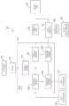
通常,此问题是通过使用如图1中所示的系统100解决的,系统100使用自动转接开关(ATS)来确保在断电期间安全过渡到本地发电源。如本领域已知的,ATS是在两个源之间切换负载的电开关。如图1中可见,系统100包括市电电源105、主仪表110和耦连至主仪表110用于从市电电源105接收电力的负载中心115。负载中心115包括若干常规的断路器,包括常规的主断路器120、若干常规的支路断路器125和常规的本地能源(LER)断路器130(其只是如下文描述的耦连至本地发电源的常规断路器)。如图1中可见,常规的支路断路器125A和125B耦连至若干“非关键”负载130(即已经被事先确定为在公用电力断电情况下不被配置成接收备用电力的负载)并为这些负载提供保护。剩下的常规的支路断路器(标记为125C)耦连至ATS 135(或者替代性地另一开关装置,诸如手动转接开关)。ATS 135的输出向副配电盘(sub panel)140提供,副配电盘140又馈送若干预定的“关键”负载145(即已经被事先确定为在公用电力断电情况下被配置成接收备用电力的负载)。此外,系统100包括本地发电源150,其可以是(例如但不限于)耦连至逆变器的PV模块或者任何其它适当的分布式电源。本地发电源150的输出向ATS 135提供,并向并网断开装置(grid tie disconnect)155提供。因此,ATS有两个输入(即从常规的支路断路器125C接收的输出和从本地发电源150接收的输出)和在2个输入之间可选择的单个输出。Typically, this problem is addressed by using a
操作中,在正常操作条件下,其中,市电电源105并不正在经历断电,自动转接开关135以其中从常规的支路断路器125接收的输入耦连至向副配电盘140提供的输出的方式被配置。此外,在此正常条件下,并网断开装置155被闭合使得本地发电源150能够把电力向市电电源105反馈。当市电电源105经历断电时,并网断开装置155被打开,以便把本地发电源150与负载中心115和市电电源105隔离,因此保护可能正在公用电网上工作的任何工人。一旦并网断开装置155被打开,自动转接开关135可以被切换到其中从本地发电源150接收的输入耦连至向副配电盘140提供的输出的配置。结果,在此断电条件下,预定的关键负载145能够从本地发电源150接收电力。In operation, under normal operating conditions in which the
尽管上文描述的系统100是有效的,但是其会向住宅电气系统带来额外层面的成本和复杂性。而且,系统100是受限制的,原因是其必须基于预定的负载资料(即在断电期间要由本地发电源150供电的某些预定负载的负载资料)事先确定大小并进行配置。要认识到,这消除了在确定哪些负载会由本地发电源150供电时的任何的灵活性。While the
发明内容SUMMARY OF THE INVENTION
在一个实施例中,提供了一种用于管理电气系统的设备。所述设备包括:主断路器,其被构造为耦连至市电电源;LER断路器,其被构造为耦连至本地发电源;若干支路断路器,每个支路断路器被构造为耦连至一个或多个负载;以及控制组件。所述控制组件被构造为响应于所述市电电源正经历断电的确定:使所述主断路器被打开;确定所述若干支路断路器的哪一个或多个要从所述本地发电源接收备用电力;使所述支路断路器被配置成使得只有确定的所述若干支路断路器的一个或多个支路断路器处于闭合条件;以及使所述本地发电源被激活。In one embodiment, an apparatus for managing an electrical system is provided. The apparatus includes: a main circuit breaker configured to be coupled to a mains power source; an LER circuit breaker configured to be coupled to a local power generation source; a number of branch circuit breakers, each branch circuit breaker configured to coupled to one or more loads; and a control assembly. The control assembly is configured to, in response to a determination that the mains power source is experiencing an outage: cause the main circuit breaker to be opened; determine which one or more of the number of branch circuit breakers are to be sourced from the local source; A power source receives backup power; causes the branch circuit breakers to be configured such that only one or more branch circuit breakers of the determined number of branch circuit breakers are in a closed condition; and causes the local power generation source to be activated.
在另一实施例中,提供了一种用于控制电气系统的方法,所述电气系统包括在负载中心提供的并耦连至市电电源的主断路器、在所述负载中心提供的并耦连至本地发电源的LER断路器和在所述负载中心提供的并各自耦连至一个或多个负载的若干支路断路器。所述方法包括:确定在所述负载中心中所述市电电源正在经历断电;响应于确定所述市电电源正在经历断电,通过向所述主断路器提供第一通信信息使所述主断路器被打开;确定所述若干支路断路器的哪一个或多个要从所述本地发电源接收备用电力;使所述支路断路器被配置成使得通过向不包括所述若干支路断路器的所述一个或多个的支路断路器提供第二通信信息,只有确定的所述若干支路断路器的一个或多个支路断路器处于闭合条件;以及通过向所述本地发电源提供第三通信信息使所述本地发电源被激活。In another embodiment, a method for controlling an electrical system is provided, the electrical system comprising a main circuit breaker provided at a load center and coupled to utility power, a parallel coupled circuit provided at the load center An LER circuit breaker connected to a local power generation source and a number of branch circuit breakers provided at the load center and each coupled to one or more loads. The method includes determining that the mains power source is experiencing a power outage in the load center; in response to determining that the mains power source is experiencing a power outage, causing the mains circuit breaker to provide first communication information. the main circuit breaker is opened; determining which one or more of the number of branch circuit breakers is to receive backup power from the local power generation source; causing the branch circuit breaker to be configured such that the number of branch circuit breakers is not included by the branch circuit breakers of said one or more of circuit breakers providing second communication information that only one or more branch circuit breakers of said number of branch circuit breakers determined are in a closed condition; and by sending said local The power generation source provides the third communication to cause the local power generation source to be activated.
附图说明Description of drawings
在结合附图阅读下面对优选实施例的描述时可以从其获得对公开的构思的全面理解,附图中:A full understanding of the disclosed concepts can be obtained from the following description of the preferred embodiments when read in conjunction with the accompanying drawings, in which:
图1是在断电期间使用自动转接开关以确保安全过渡到本地发电源的现有技术的系统的示意图;1 is a schematic diagram of a prior art system using an automatic transfer switch to ensure a safe transition to local generation during a power outage;
图2是根据本发明的示例性实施例用于在断电期间确保安全过渡到本地发电源的系统的示意图;2 is a schematic diagram of a system for ensuring a safe transition to a local power generation source during a power outage according to an exemplary embodiment of the present invention;
图3是示出根据本发明的示例性实施例图2的系统的控制方法的流程图;FIG. 3 is a flowchart illustrating a control method of the system of FIG. 2 according to an exemplary embodiment of the present invention;
图4-7是可以用来实现图2的系统和图3的方法的示例性断路器的图。4-7 are diagrams of exemplary circuit breakers that may be used to implement the system of FIG. 2 and the method of FIG. 3 .
具体实施方式Detailed ways
如本文中使用的方向性用语(比方说例如左、右、前、后、顶、底和其派生词)涉及图中所示的元件的方向,除非在文本中明确指出,否则不是对权利要求的限制。Directional terms (such as, eg, left, right, front, rear, top, bottom, and derivatives thereof) as used herein refer to the orientation of elements shown in the figures and, unless explicitly stated in the text, do not refer to the claims limits.
如本文中使用的术语“数目”表示1或者大于1的整数(即多个)。The term "number" as used herein means 1 or an integer greater than 1 (ie, a plurality).
如本文中使用的两个或更多个零件被“耦连”在一起的陈述表示所述零件或者直接地或者通过一个或多个中间零件连接而连接在一起。As used herein, the statement that two or more parts are "coupled" together means that the parts are connected together either directly or through the connection of one or more intervening parts.
如本文中使用的术语“组件”旨在指与计算机有关的实体,或者是硬件,硬件和软件的组合,软件或在执行中的软件。例如,组件可以是但不局限于是在处理器上运行的过程、处理器、对象、可执行的执行线程、程序和/或计算机。作为示意,在处理器或服务器上运行的应用以及处理器或服务器可以是组件。一个或多个组件可以驻存在过程和/或执行线程内,并且组件可以位于一个计算机/处理器上,和/或分布在两个或更多个计算机/处理器之间。The term "component" as used herein is intended to refer to a computer-related entity, either hardware, a combination of hardware and software, software or software in execution. For example, a component may be, but is not limited to, a process running on a processor, a processor, an object, an executable thread of execution, a program, and/or a computer. By way of illustration, applications running on a processor or server and the processor or server may be components. One or more components can reside within a process and/or thread of execution, and a component can be localized on one computer/processor and/or distributed between two or more computers/processors.
图2是根据公开的构思的一个非限制的示例性实施例的配电系统200。如本文中更加详细地描述的,系统200包括可控(并且在示例性实施例中是能够计量的)断路器的系统,包括主断路器和在主断路器下游的支路断路器的子集。系统200实现一种控制方法(图3中图示并关于图3详细描述的),其能够使本地发电源(诸如但不限于耦连至逆变器的PV模块)在断电条件下安全地投入使用,而无需使用ATS(诸如图1中所示的ATS 135)或相似的开关装置。如本文中更加详细地描述的,在示例性实施例中,控制方法确定何时存在公用电力断电,隔离耦连至公用电网的负载配电盘,使本地发电源安全地在线持续需要的时间,协调负载需求与本地发电供应容量,并在断电条件平息时安全地恢复电网电力。关于负载需求与本地发电供应容量的协调,所述方法使用控制元件,其中,负载需求被管理(即通过闭合关联的断路器,负载被耦连至本地发电供应),以便确保负载需求不会超出实际的本地发电供应容量。所述方法可以可选地使用多个本地发电源之间的同步(如果提供的话)和/或与电网电力的相位同步以允许电力的无缝或“不眨眼(blinkless)”的传输。如本文中详细描述的,通过直接地控制系统200中的断路器而不是使用传统的开关机构(诸如ATS),实现此控制方法。通过跳闸主断路器,耦连至公用电网的负载配电盘可以从电网隔离,并且通过切换若干支路断路器使其接通和关断,负载需求可以被平衡,以匹配本地发电供应容量。换言之,负载的电力需求可以被控制,以便防止其超过本地发电源的供电容量。实际上,系统200能够动态确定从本地发电源(本文中描述的本地发电源245)可用的本地发电供应的量,然后与系统200中的其它断路器(本文中描述的支路断路器230)协调,从而只闭合能够由本地发电源支撑的那些断路器而不过载。FIG. 2 is a
在公开的构思的非限制的示例性实施例中,如本文中描述的系统200中使用的每个可控断路器是电力售卖机(PVM)断路器400的形式,电力售卖机(PVM)断路器400在由本发明的受让人拥有的美国专利申请公开号2014/0211345和2014/0214218中详细地描述,这两件申请的公开内容通过引用全部被并入本文中。然而,要理解系统200中PVM断路器400的使用只是出于示意目的,不是限制性的,还可以使用可控断路器的替代类型。例如但不是限制,系统200中使用的一个或多个可控断路器可以是如名称为“Microgrid SystemStructured to Detect Overload Conditions and Take Corrective Actions RelatingThereto”的美国专利申请序号14/264,409中描述的智能断路器,该申请由本申请的受让人拥有,并通过引用被并入本文中,或者是在例如美国专利号5,301,083、5,373,411、6,477,022和6,507,255中描述的具有与主可分离触点串联的第二对可分离触点的远程可控断路器。In a non-limiting exemplary embodiment of the disclosed concept, each controllable circuit breaker used in
示例性PVM断路器400在图4中示意性示出,包括以下的四种类型的功能:(1)电路保护功能,包括传统的热-磁电路保护、短路保护、过载保护、接地故障保护、电弧故障保护和/或根据需要的其它类型的保护,(2)支路电路计量功能,包括公用事业等级净计量(±0.2%)和加时间戳的值,(3)用于操作可控触点的远程控制功能,包括接通/关断控制中继功能,其与断路器跳闸机构独立,(4)有线和/或无线通信功能,包括用于发送和接收仪表控制和状态信息的功能,用于在断电条件期间通信的备用功能,以及可选的负载特定的控制特征/信号,其被配置成控制特殊类型的连接负载(诸如能够直接地对电动车辆(EV)充电的断路器的电动车辆供应设备(EVSE)形式、直接地通过所述电路的打开和闭合或者通过低压信号传送基本上消除控制恒温器的需要的能够直接地并独立地控制风扇、压缩机以及加热单元的HVAC断路器,以及包括调光能力的照明控制断路器;如本文中描述的LER断路器240是另一示例,其中,可以使用负载特定的控制特征以根据需要把连接的本地发电源接通和关断)。在示例性实施例中,在微控制器401的控制下的功能(2)-(4)可以是例如但不限于微处理器或任何其它适当的处理装置。此外,尽管在示例性实施例中,功能(1)不由微控制器401控制,但要理解,在替代性实施例中,功能(1)还可以受微控制器401的控制。而且,在图示的实施例中,PVM断路器400还包括由微处理器401控制的指示器功能(标记为(5)),以指示诸如故障状态和/或流过PVM断路器400的电流的信息。An exemplary
在继续进行对根据示例性实施例的系统200的个体或元件和操作的详细描述之前,将在下文参照图5、6和7,详细描述如在美国专利申请公开号2014/0211345和2014/0214218中示出的PVM断路器400的示例性实现方式。Before proceeding with a detailed description of the individuals or elements and operation of the
PVM断路器400能够支持对于通过PVM断路器400消耗的能量对用户进行计费。例如,计量功能402(图5)使用逻辑电路404(图5和6)在存储器410中的永久性数据库408中存储加时间戳的能量值406。计量功能402和逻辑电路404都在PVM断路器400的外壳内。在某些时间戳中,能量值406可以被“标记”为属于若干特定用户,这为这些若干特定用户中的每一个提供能量分配。例如,当电负载412(在虚线绘图中示出)被插入时,能量能够被适当地分配给特定的电力电路(例如在端子414、416处向电负载412分配(在图5中的虚线绘图中示出))。The
电源,诸如电力公用事业418(在图5和6中的虚线绘图中示出),向在配电盘或负载中心(未示出)处的断路器接头(breaker stab)420(例如从带电线或母线(未示出))和中性抽头422(例如,向中性母线(未示出)))供应电力,当电源准备好对用户计费时,能够以各种方式通过经由扩展端口424(图6)或者可选地通过内置的无线接口(例如不限于Wi-Fi;蓝牙)进行的通信来完成。一种示例性方法是在从对应的配电盘或负载中心(未示出)的主断路器(未示出,但除了具有相对较大的额定电流值之外,其可以基本上与断路器400相同或相似)读数时总能量的“仪表读数”。“仪表读数”的值与例如来自前一个月的读数的“仪表读数”的值比较,并且对差值计费。A power source, such as power utility 418 (shown in the dashed line drawings in FIGS. 5 and 6 ), to a
替代性地,电力公用事业418能够全部下载每个断路器(诸如400)的数据库408,适当地查询能量值406,然后使用时间戳、特定的电路和任何分配标志应用适当的费率结构。Alternatively, the
图5-7示出示例性的可控PVM断路器400,其可以包括用于通信和/或若干不同的附加模块426的可选的支持部件,如将要讨论的。5-7 illustrate an exemplary controllable
参照图5,示例性PVM断路器400可以包括若干可选的附加模块426。通过在电源418和负载412之间的PVM断路器400的交流(AC)电气路径包括热-磁保护功能428、计量功能402和可控的可分离触点430。AC-DC电源432向例如逻辑电路404和通信电路434供应DC电。替代性地,DC电源432可以位于PVM断路器400的外部并向其供应DC电。若干可选的附加模块426可以提供特定的逻辑和/或I/O功能和通信电路436。可选的远程软件功能438、440可以可选地与通信电路434、436通信。Referring to FIG. 5 , the example
图6示出示例性PVM断路器400的更多细节,其包括外部断路器手柄442,手柄442与热磁跳闸功能428合作以打开、闭合和/或复位相应的可分离触点429(图7)、由逻辑电路404控制的OK指示器444和向逻辑电路404输入的测试/复位按钮446。6 shows more details of the exemplary
在此示例中,带电线和中性线通过PVM断路器400以及相应的电流传感器448、449,电压传感器450、451和每条线或电导体的可分离触点430A、430B。计量功能402的功率计量电路452从电流传感器448、449和电压传感器450、451输入并向逻辑电路404输出相应的功率值,逻辑电路404使用定时器/时钟功能454以在存储器410的数据库408中提供相应的加时间戳的能量值406。电流传感器448、449可以与相应的可分离触点430A、430B串联地电连接,可以是耦连至电力线的电流互感器或者可以是任何适当的电流感测装置。电压传感器450、451可以与相应的可分离触点430A、430B串联地电连接至相应的电力线,可以是电压互感器或者可以是任何适当的电压感测装置。In this example, the live and neutral lines pass through the
图7是示例性PVM断路器400的示例性单线图。尽管示出了一相(例如带电线和中性点),但公开的构思可应用于具有任何数目的相或电极的PVM断路器。通过到达母线(未示出)的终端420接收带电线。电流流过热-磁过载保护功能428的第一断路元件429,并通过一组可控可分离触点430(在此示例中只示出带电线的一组触点)流向负载端子414。第一电流互感器(CT)448提供具有可定制跳闸设置的电流感测和接地故障检测。来自负载412的返回电流路径(图5)从负载端416提供用于负载中性点回到中性抽头422,以电连接到例如配电盘或负载中心(未示出)的中性线。第二CT 449提供具有可定制跳闸设置的电流感测和接地故障检测。CT 448、449的输出被逻辑电路404输入,逻辑电路404控制可控可分离触点430。电源432从带电线和中性线接收电力。逻辑电路通信电路434还输出到扩展端口424的通信端点456(图6)。FIG. 7 is an exemplary one-line diagram of an exemplary
再参照图2,现在将描述根据非限制的示例性实施例的系统200的元件。系统200包括耦连至主仪表210的市电电源205。负载中心215耦连至主仪表210的输出用于从市电电源205的公用电网那里接收公用电。负载中心215包括耦连至主仪表210的主断路器220。在替代性实施例中,主仪表210可以省略,负载中心215直接连接到市电电源205。在任何这种替代性实施例中,计量功能反而可以由主断路器220提供,主断路器220如下文描述的配置有这种计量功能。Referring again to FIG. 2, elements of
负载中心215还包括主母线225和耦连至主母线225的若干支路断路器230。如图2中可见,每个支路断路器230耦连至关联的一个负载或若干负载235。在图示的示例性实施例中,负载中心215为专用电路馈电,意味着每个支路断路器230为单个负载235馈电并耦连至单个负载235(然而,每个负载235不一定是专用电路)。不过,要理解,这旨在只是示例性的,在公开的构思的范围内,还可以使用其中非专用电路和/或专用电路和非专用电路的组合的其它配置。负载中心215还包括具有耦连于其上的本地发电源245的LER断路器240。本地发电源245可以是任何类型的分布式电源,诸如但不限于使用PV模块、发电机、风力涡轮机、天然气涡轮机或电池储存的分布式电源。The
在非限制的图示的示例性实施例中,主断路器220、支路断路器230和LER断路器240分别是在本文中其它地方详细描述的PVM断路器400。因此,这些断路器中的每一个都具有如本文中描述的电路保护功能、支路电路计量功能、远程控制功能和通信功能(图4)。In the non-limiting illustrated exemplary embodiment,
而且,如图2中可见,负载中心215包括控制组件250。控制组件250被构造为如本文中描述的控制系统200的操作,并且具体地被构造为并被编程为实现图3中示出的并在下面详细描述的控制方法。控制组件250可以驻存在负载中心215内的任何地方,诸如在主断路器220、支路断路器230、LER断路器240内,或者可以扩展并分布在这些元件的一个或多个上。在替代性实施例中,控制组件可以是具有处理器和插入到负载中心215中的可编程存储器的计算装置。在又一个替代性实施例中,控制组件可以位于远离负载中心215处,仍然如本文中描述的与负载中心250的各方面通信或对其进行控制。在本文中描述的示例性实施例中,出于图示目的,控制组件250形成主断路器220的一部分以使得主断路器220能够充当负载中心215的系统协调者。Also, as can be seen in FIG. 2 , the
参照图3,现在将描述根据示例性实施例的公开的构思的控制方法。所述方法在步骤300开始,其中,检测到市电电源205处的断电。在示例性实施例中,由主断路器220通过感测来自市电电源205的电压已经下降到低于某个预定的水平来检测此断电。接着,在步骤305,控制组件250打开主断路器220以把负载中心215和本地发电源245与市电电源205的主电网隔离。然后,在步骤310,控制组件通过向LER断路器240传送控制信号(通过适当的有线或无线连接)使LER断路器240被打开。替代性地,步骤305和310的顺序可以被交换,使得步骤310被首先执行,之后是步骤305。接着,在步骤315,控制组件250识别支路断路器230的哪些(如果有的话)不会从本地发电源245接收备用电力。此步骤可以以各种方式执行,并包括基于一个或多个存储的和/或测量的参数和/或功能确定哪些断路器要接收备用电力哪些断路器不接收备用电力。例如,控制组件250可以被编程为识别在断电情况下要接收备用电力的负载235的某些预定负载(即“关键负载”),因此在步骤315,将识别不是“关键负载”的负载235。在此具体实现方式中“关键负载”的编程和识别可以通过公用事业和/或负载中心215的本地用户进行,因此,公开的构思的这方面通过允许在断电条件中动态的负载管理提供备用电力供应的大的灵活性。“关键负载”的编程和识别还可以被区分优先次序,使得当检测到断电时,基于根据预定的优先级可用的电力,负载235会被选择为接收备用电力。替代性地,控制组件250可以被编程以基于预定的参数(诸如时间和/或日期)动态地选择负载235中要接收备用电力的那些负载,基于这些参数的当前状态某些负载235被识别以用于接收备用电力。而且,许多附加的替代性控制方案也是可能的。例如,在一个替代性控制方案中,每个负载235被事先识别为“关键的”或“非关键的”,控制组件250与由关联的支路断路器230测量的计量数据协作以确保无需使本地发电源245过载/过度疲劳(即无需超过本地发电源的供应容量)使尽可能多的“关键”负载可工作。在另一替代性控制方案中,每个负载235被分配一个优先级,例如,“1”是最高优先级,等等。控制组件250然后与由关联的支路断路器230测量的计量数据协作以确保无需使本地发电源245过载/过度疲劳使尽可能多的最高优先级的负载235可工作。因此,上文提供的第一示例性方案基本上是此第二控制方案的两优先级示例。在又一另外的替代性控制方案中,每个负载235被分配一个优先级和优选的“运行时间”。控制组件250然后与计量数据和时间数据协作以确保尽可能多的最高优先级负载235对其特定的运行时间是可操作的,并且在负载235的运行时间结束时,其它较低优先级的负载235可以使其关联的支路断路器230闭合。在又一替代性控制方案中,控制组件250可以执行上面方案中的任何一个,借助其中的“用户覆盖”组件,用户可以选择要被打开和/或闭合的具体的支路断路器230。Referring to FIG. 3 , a control method according to the disclosed concept of an exemplary embodiment will now be described. The method begins at
在步骤315之后,方法前进到步骤320,其中,控制组件250使得在步骤315中识别的支路断路器230B被打开。接着,在步骤325,控制组件250使信号向本地发电源245(使用这些组件之间的适当的有线和/或无线连接)发送,这使得本地发电源245被激活。接着,在步骤330,控制组件250通过使信号向LER断路器240发送(使用这些组件之间的适当的有线和/或无线连接),使得LER断路器240被闭合。在步骤330之后,方法前进到步骤335,其中,系统200能够依靠来自本地发电源245的电力运行,电力被提供至在步骤315中没有被识别的任何负载235。After
在步骤340,对是否已经恢复在市电电源205处的公用电力进行确定。如果答案是否定的,则方法返回步骤335。此时,负载中心215的用户可以使用控制组件250重新配置系统,以改变处于打开的(或闭合的)支路断路器230以及还有接收电力的负载235。例如,如果在断电事件中,用户确定他们现在需要一开始曾被确定为“非关键”或低优先级的负载235,则用户现在能够闭合电路,并且如果需要,打开较低优先级的另一电路,以便防止本地发电源240的过度疲劳(如下文描述的)。例如,如果用户确定他们需要对一开始曾被确定为“非关键的”EV再充电,则用户可以选择暂时关闭其空调单元,以便允许对其EV充电。然后,一旦EV已经被充分地充电,则用户可以选择关闭EVSE,重新打开其空调单元。这为用户提供传统的系统不能提供的大量的额外的灵活性和可塑性。不过,应当注意,要管理/匹配连接的负载235,以便不使本地发电源245的容量过度疲劳并且或者使其反馈断路器跳闸或者使其过度疲劳到故障点。在示例性实施例中,控制组件250包括帮助负载235的管理和匹配的控制特征,以便防止本地发电源245的过度疲劳。例如,在进行任何改变之前,控制组件250可以检查计量数据,并确定改变会对负载需求有什么影响,并防止可能导致过度疲劳条件的任何变化。然而,如果步骤340处的答案是肯定的,则方法前进到步骤345,其中,控制组件250使LER断路器240被打开。接着,在步骤350,控制组件250使本地发电源245被去激活。之后,在步骤355,控制组件250使主断路器220被闭合。然后,在步骤360,控制组件250通过向那些支路断路器230发送一个或多个信号(使用这些组件之间的适当的有线和/或无线连接)使所有的支路断路器230被闭合。替代性地,步骤355和360的顺序可以交换,使得步骤360被首先执行之后是步骤355。最后,在步骤365,控制组件250使本地发电源245被激活,使得既然断电已经被校正,本地发电源245能够返回反向馈电的市电电源205。At
因此,图3中所示的并在上文描述的方法提供在断电情况下经由本地发电源切换到备用电力,在断电之后返回公用电力的安全机构,其不需要价格高的复杂和不灵活的切换机构,诸如ATS(图1)。Thus, the method shown in FIG. 3 and described above provides a safety mechanism for switching to backup power via a local generation source in the event of a power outage, and returning to utility power after a power outage, which does not require expensive complexity and inconvenience Flexible switching mechanisms such as ATS (Figure 1).
而且,尽管图2中所示的系统200和关于图3描述的方法只包括单个本地发电源245,但要理解,公开的构思还可以用在包括多个本地发电源245和多个LER断路器240的系统中。在这样的替代性实现方式中,如在控制组件250中实现的方法可能需要确保多个本地发电源245能够相互同步。在一个示例性实施例中,一个本地发电源245会被提升变成是“公用事业的”,并会连接至主母线225。该本地发电源245然后为其它本地发电源245提供与之同步的润湿电压(wetting voltage)。在另一替代性实施例中,控制组件250配置有关于本地发电源245的元数据,例如用于太阳能实施例的天气数据或用于发电机实施例的燃料消耗的燃料容量,从支路断路器230接收的计量数据可以用来预测本地发电源245能够持续向连接的负载235提供多长时间的电力的“剩余的正常运行时间”。借助可以从其导出重要统计数据(诸如但不限于“剩余的正常运行时间”)的元数据的加入,可以更加智能地做出负载管理决策。Furthermore, although the
在又一替代性实施例中,图2中所示的本地发电源245可以不在客户位置(诸如住宅)提供,而是在配电系统(例如“邻居”本地发电源)内旨在用于一组公用事业客户的本地发电源。例如,本地发电源245可以是本地能量储存装置(例如电池),其被配置成如果发生断电,则为特定区域中的若干客户服务。在这样的配置中,一个或多个客户可以具有如本文中描述的负载中心215,负载中心215具有耦连至此“邻居”本地发电源245的LER断路器240。因此,如本文中描述的,具有这种负载中心215的每个客户能够确定如果发生断电哪些负载215会从“邻居”本地发电源245接收备用电力。此外,在示例性实施例中,由于主断路器220、LER断路器240和支路断路器230是如本文中描述的具有计量功能的每个PVM断路器400,提供“邻居”本地发电源245的公用事业将能够针对其使用量对客户进行计费。在一个示例中,客户使用量可以是不受限的,客户将为消费的任何电力付费。在另一实施例中,客户可以认购(并支付)在断电情况下的特定量的备用电力,其对“邻居”本地发电源的访问会局限于由其认购覆盖的电力量(即一旦已经消费认购的电力量,则LER断路器240会被打开)。在这种情况下,客户可能希望如本文中描述的主动地管理负载中心215的负载235,以便定量配给他们可以获得的电力。In yet another alternative embodiment, the local
尽管已经详细地描述了公开的构思的特定实施例,但本领域技术人员会认识到根据本公开的全部教导,可以发展对这些细节的各种变形和替代。因此,公开的具体排列结构旨在只是示意性的,不是关于对公开的构思的范围的限制,公开的构思的范围被赋予所附权利要求及其任何和全部等同物的全部广度。Although specific embodiments of the disclosed concepts have been described in detail, those skilled in the art will recognize that various modifications and substitutions to these details can be developed in light of the overall teachings of this disclosure. Therefore, the specific arrangements disclosed are intended to be illustrative only, and are not intended to be limiting as to the scope of the disclosed concepts, which are to be accorded the full breadth of the appended claims and any and all equivalents thereof.
Claims (13)
Translated fromChineseApplications Claiming Priority (3)
| Application Number | Priority Date | Filing Date | Title |
|---|---|---|---|
| US201462045864P | 2014-09-04 | 2014-09-04 | |
| US62/045,864 | 2014-09-04 | ||
| PCT/US2015/024423WO2016036419A1 (en) | 2014-09-04 | 2015-04-06 | System and method for switching an electrical system to backup power during a utility power outage |
Publications (2)
| Publication Number | Publication Date |
|---|---|
| CN106688155A CN106688155A (en) | 2017-05-17 |
| CN106688155Btrue CN106688155B (en) | 2020-11-17 |
Family
ID=52875817
Family Applications (1)
| Application Number | Title | Priority Date | Filing Date |
|---|---|---|---|
| CN201580046802.9AActiveCN106688155B (en) | 2014-09-04 | 2015-04-06 | System and method for switching electrical system to standby power in a utility power outage |
Country Status (7)
| Country | Link |
|---|---|
| EP (1) | EP3189572A1 (en) |
| CN (1) | CN106688155B (en) |
| BR (1) | BR112017003386B1 (en) |
| CA (1) | CA2959590C (en) |
| MX (1) | MX2017002146A (en) |
| RU (1) | RU2690008C1 (en) |
| WO (1) | WO2016036419A1 (en) |
Families Citing this family (16)
| Publication number | Priority date | Publication date | Assignee | Title |
|---|---|---|---|---|
| EP3232529A1 (en) | 2016-04-14 | 2017-10-18 | DET International Holding Limited | Power supply arrangement |
| US11114855B2 (en)* | 2016-05-24 | 2021-09-07 | Solaredge Technologies Ltd. | Load management in hybrid electrical systems |
| FR3053808B1 (en)* | 2016-07-07 | 2020-03-06 | Schneider Electric Industries Sas | METHOD FOR CONTROLLING AN ELECTRICAL INSTALLATION FROM A REMOTE LOCATION |
| WO2018053283A2 (en) | 2016-09-15 | 2018-03-22 | Racepoint Energy, LLC | System and methods for creating dynamic nano grids and for aggregating electric power consumers to participate in energy markets |
| US11316471B2 (en) | 2016-11-08 | 2022-04-26 | Tesla, Inc. | Manual transfer switch for onsite energy generation and storage systems |
| US10852799B2 (en)* | 2017-07-14 | 2020-12-01 | Analog Devices Global Unlimited Company | Adaptive use of multiple power supplies in communication systems |
| CN109560606A (en)* | 2017-09-26 | 2019-04-02 | 中兴通讯股份有限公司 | A kind of alternating current power generation automatic switching method and device |
| CN109696629A (en)* | 2018-12-21 | 2019-04-30 | 中广核研究院有限公司 | Nuclear power plant's diesel generating set test method |
| CA3153699A1 (en) | 2019-09-11 | 2021-03-18 | Savant Systems, Inc. | Energy management system and methods |
| US11799272B2 (en)* | 2019-12-13 | 2023-10-24 | Eaton Intelligent Power Limited | Dual contactor electrical panelboard assembly, systems and methods |
| CN112682973B (en)* | 2020-12-21 | 2023-02-03 | 北京能高自动化技术股份有限公司 | Load heating time control method applied to photovoltaic heat storage system |
| US11817701B2 (en) | 2021-01-29 | 2023-11-14 | Eaton Intelligent Power Limited | Multi-port split-phase power system |
| US11424641B1 (en) | 2021-06-09 | 2022-08-23 | Savant Systems, Inc. | Flexible load management system |
| US11621580B2 (en) | 2021-08-31 | 2023-04-04 | Savant Systems, Inc. | Microgrid switchover using zero-cross detection |
| WO2024112979A1 (en)* | 2022-11-23 | 2024-05-30 | University Of South Africa | Green energy and grid network management |
| CN116629547A (en)* | 2023-05-25 | 2023-08-22 | 山西省安装集团股份有限公司 | A real-time monitoring and analysis method, device and electronic equipment for urban comprehensive energy system |
Citations (1)
| Publication number | Priority date | Publication date | Assignee | Title |
|---|---|---|---|---|
| CN103391816A (en)* | 2011-02-14 | 2013-11-13 | 贝克曼考尔特公司 | Regenerative braking safety system and method of use |
Family Cites Families (7)
| Publication number | Priority date | Publication date | Assignee | Title |
|---|---|---|---|---|
| US7015599B2 (en)* | 2003-06-27 | 2006-03-21 | Briggs & Stratton Power Products Group, Llc | Backup power management system and method of operating the same |
| RU2318281C1 (en)* | 2006-11-13 | 2008-02-27 | Общество с ограниченной ответственностью "Технологическая лаборатория" | Computerized system for no-break power supply to stationary equipment |
| US7615888B2 (en)* | 2007-04-23 | 2009-11-10 | Eaton Corporation | Multiple generator loadcenter and method of distributing power from multiple generators |
| RU2353035C1 (en)* | 2008-05-12 | 2009-04-20 | Юрий Петрович Баталин | Electric power complex |
| US20140088780A1 (en)* | 2012-09-26 | 2014-03-27 | Hongxia Chen | Automatic local electric management system |
| US20140211345A1 (en)* | 2013-01-30 | 2014-07-31 | Eaton Corporation | Annunciating or power vending circuit breaker for an electric load |
| US10067199B2 (en)* | 2013-01-30 | 2018-09-04 | Eaton Intelligent Power Limited | Electric power distribution system including metering function and method of evaluating energy metering |
- 2015
- 2015-04-06BRBR112017003386-0Apatent/BR112017003386B1/enactiveIP Right Grant
- 2015-04-06EPEP15716961.6Apatent/EP3189572A1/enactivePending
- 2015-04-06CACA2959590Apatent/CA2959590C/enactiveActive
- 2015-04-06MXMX2017002146Apatent/MX2017002146A/enunknown
- 2015-04-06WOPCT/US2015/024423patent/WO2016036419A1/enactiveApplication Filing
- 2015-04-06CNCN201580046802.9Apatent/CN106688155B/enactiveActive
- 2015-04-06RURU2017109161Apatent/RU2690008C1/enactive
Patent Citations (1)
| Publication number | Priority date | Publication date | Assignee | Title |
|---|---|---|---|---|
| CN103391816A (en)* | 2011-02-14 | 2013-11-13 | 贝克曼考尔特公司 | Regenerative braking safety system and method of use |
Also Published As
| Publication number | Publication date |
|---|---|
| RU2690008C1 (en) | 2019-05-30 |
| CA2959590A1 (en) | 2016-03-10 |
| CA2959590C (en) | 2023-10-10 |
| BR112017003386A2 (en) | 2017-11-28 |
| WO2016036419A1 (en) | 2016-03-10 |
| CN106688155A (en) | 2017-05-17 |
| BR112017003386B1 (en) | 2022-08-09 |
| EP3189572A1 (en) | 2017-07-12 |
| MX2017002146A (en) | 2017-05-03 |
Similar Documents
| Publication | Publication Date | Title |
|---|---|---|
| CN106688155B (en) | System and method for switching electrical system to standby power in a utility power outage | |
| US12227083B2 (en) | Annunciating or power vending circuit breaker for an electric load | |
| US11552500B2 (en) | Systems and methods for managing electrical loads | |
| US12322963B2 (en) | Multilayer control for managing power flow | |
| US20230120740A1 (en) | Integrated home energy management and electric vehicle charging | |
| US9413195B2 (en) | Microgrid system structured to detect overload conditions and take corrective actions relating thereto | |
| TW201320524A (en) | Multipurpose power management system and method | |
| US9787080B2 (en) | Microgrid distribution manager with dynamically adjustable trip curves for multi-source microgrids | |
| US20170214225A1 (en) | Interconnect and metering for renewables, storage and additional loads with electronically controlled disconnect capability for increased functionality | |
| US9903893B2 (en) | Method and device for registering electrical consumption and generation | |
| US20180110150A1 (en) | Scalable electric provisioning system | |
| US12381413B1 (en) | Energy controller in meter socket adapter connected household microgrid | |
| CN223218874U (en) | Energy storage inverter system and energy storage system |
Legal Events
| Date | Code | Title | Description |
|---|---|---|---|
| PB01 | Publication | ||
| PB01 | Publication | ||
| SE01 | Entry into force of request for substantive examination | ||
| SE01 | Entry into force of request for substantive examination | ||
| TA01 | Transfer of patent application right | Effective date of registration:20190429 Address after:Dublin, Ireland Applicant after:Eaton Intelligent Power Co.,Ltd. Address before:Ohio, USA Applicant before:Eaton Corp. | |
| TA01 | Transfer of patent application right | ||
| GR01 | Patent grant | ||
| GR01 | Patent grant |