CN106680974B - camera lens - Google Patents
camera lensDownload PDFInfo
- Publication number
- CN106680974B CN106680974BCN201710085671.6ACN201710085671ACN106680974BCN 106680974 BCN106680974 BCN 106680974BCN 201710085671 ACN201710085671 ACN 201710085671ACN 106680974 BCN106680974 BCN 106680974B
- Authority
- CN
- China
- Prior art keywords
- lens
- imaging
- object side
- imaging lens
- optical axis
- Prior art date
- Legal status (The legal status is an assumption and is not a legal conclusion. Google has not performed a legal analysis and makes no representation as to the accuracy of the status listed.)
- Active
Links
Images


Classifications
- G—PHYSICS
- G02—OPTICS
- G02B—OPTICAL ELEMENTS, SYSTEMS OR APPARATUS
- G02B13/00—Optical objectives specially designed for the purposes specified below
- G02B13/001—Miniaturised objectives for electronic devices, e.g. portable telephones, webcams, PDAs, small digital cameras
- G02B13/0015—Miniaturised objectives for electronic devices, e.g. portable telephones, webcams, PDAs, small digital cameras characterised by the lens design
- G02B13/002—Miniaturised objectives for electronic devices, e.g. portable telephones, webcams, PDAs, small digital cameras characterised by the lens design having at least one aspherical surface
- G02B13/0045—Miniaturised objectives for electronic devices, e.g. portable telephones, webcams, PDAs, small digital cameras characterised by the lens design having at least one aspherical surface having five or more lenses
- G—PHYSICS
- G02—OPTICS
- G02B—OPTICAL ELEMENTS, SYSTEMS OR APPARATUS
- G02B13/00—Optical objectives specially designed for the purposes specified below
- G02B13/18—Optical objectives specially designed for the purposes specified below with lenses having one or more non-spherical faces, e.g. for reducing geometrical aberration
Landscapes
- Physics & Mathematics (AREA)
- General Physics & Mathematics (AREA)
- Optics & Photonics (AREA)
- Lenses (AREA)
Abstract
Translated fromChinese
Description
Translated fromChinese技术领域technical field
本申请涉及一种摄像镜头,具体涉及一种小型化的广角摄像镜头。The present application relates to a camera lens, in particular to a miniaturized wide-angle camera lens.
背景技术Background technique
近年来,随着科技的发展,便携式电子产品逐步兴起,具有摄像 功能的便携式电子产品得到人们更多的青睐。常规的摄像镜头的感光 元件一般为CCD(Charge-CoupledDevice,感光耦合元件)或CMOS (Complementary Metal-Oxide Semiconductor,互补性氧化金属半导体 元件)。随着CCD与COMS元件性能的提高及尺寸的减小,对于相配 套的摄像镜头的小型化与成像优质化提出了更高的要求。In recent years, with the development of science and technology, portable electronic products have gradually emerged, and portable electronic products with camera functions have been favored by more and more people. The photosensitive element of a conventional camera lens is generally a CCD (Charge-Coupled Device, a photosensitive coupling element) or a CMOS (Complementary Metal-Oxide Semiconductor, a complementary metal oxide semiconductor element). With the improvement of the performance of CCD and CMOS components and the reduction of the size, higher requirements are put forward for the miniaturization and imaging quality of the matching camera lens.
因此,需要一种可适用于便携式电子产品的具有大视场角、小尺 寸以及高成像品质的摄像镜头。Therefore, there is a need for a camera lens with a large angle of view, small size, and high imaging quality that is applicable to portable electronic products.
发明内容SUMMARY OF THE INVENTION
本申请提供的技术方案至少部分地解决了以上所述的技术问题。The technical solutions provided by the present application at least partially solve the above-mentioned technical problems.
一方面,本申请提供了一种摄像镜头。该摄像镜头沿着光轴由物 侧至像侧依序包括第一透镜和多个后续透镜,并具有总有效焦距f以 及入射瞳直径EPD,其中,所述摄像镜头还包括设置在成像面上的感 光元件,所述第一透镜具有正屈折力并且其物侧面为凸面;以及所述 总有效焦距f、所述入射瞳直径EPD和所述感光元件的有效像素区域 对角线长的一半ImgH之间满足:f/EPD≤2;以及ImgH/f>0.85。本申 请的摄像镜头能够实现大孔径、超薄效果,并且具有高的成像品质。In one aspect, the present application provides a camera lens. The imaging lens includes a first lens and a plurality of subsequent lenses in sequence from the object side to the image side along the optical axis, and has a total effective focal length f and an entrance pupil diameter EPD, wherein the imaging lens further includes a lens disposed on the imaging surface. The photosensitive element, the first lens has a positive refractive power and its object side is convex; and the total effective focal length f, the entrance pupil diameter EPD and the effective pixel area of the photosensitive element half of the diagonal length ImgH between: f/EPD≤2; and ImgH/f>0.85. The imaging lens of the present application can achieve large aperture and ultra-thin effects, and has high imaging quality.
根据本申请实施方式,所述多个后续透镜包括:具有负屈折力的 第二透镜,其中,所述第一透镜和所述第二透镜在所述光轴上的间隔 距离T12与从所述第一透镜的物侧面至所述摄像镜头的成像面的轴上 距离TTL满足0.08<T12/TTL<0.12。According to an embodiment of the present application, the plurality of subsequent lenses include: a second lens having a negative refractive power, wherein the separation distance T12 between the first lens and the second lens on the optical axis is the same as the distance T12 from the The axial distance TTL from the object side of the first lens to the imaging surface of the imaging lens satisfies 0.08<T12/TTL<0.12.
根据本申请实施方式,所述多个后续透镜还包括位于所述第二透 镜与所述像侧之间的第三透镜,其中,所述第三透镜具有正屈折力, 其像侧面为凸面;以及其中,所述第一透镜和所述第二透镜在所述光 轴上的间隔距离T12与所述第二透镜和所述第三透镜在所述光轴上的 间隔距离T23满足4<T12/T23<13.5。According to an embodiment of the present application, the plurality of subsequent lenses further include a third lens located between the second lens and the image side, wherein the third lens has a positive refractive power, and the image side is convex; and wherein, the separation distance T12 between the first lens and the second lens on the optical axis and the separation distance T23 between the second lens and the third lens on the optical axis satisfy 4<T12 /T23<13.5.
根据本申请实施方式,所述多个后续透镜还包括位于所述第三透 镜与所述像侧之间的第四透镜和第五透镜,其中,所述第四透镜的物 侧面为凹面、以及所述第五透镜的像侧面为凹面。According to an embodiment of the present application, the plurality of subsequent lenses further include a fourth lens and a fifth lens located between the third lens and the image side, wherein the object side of the fourth lens is concave, and The image side surface of the fifth lens is concave.
根据本申请实施方式,所述第三透镜像侧面和所述光轴的交点至 所述第一透镜物侧面的有效半径顶点之间的轴上距离SAG32与所述 第四透镜物侧面和所述光轴的交点至所述第一透镜物侧面的有效半径 顶点之间的轴上距离SAG41满足0.5<SAG32/SAG41<1。According to the embodiment of the present application, the on-axis distance SAG32 between the intersection of the image side surface of the third lens and the optical axis to the apex of the effective radius of the object side surface of the first lens is related to the object side surface of the fourth lens and the The on-axis distance SAG41 between the intersection of the optical axes and the vertex of the effective radius of the object side surface of the first lens satisfies 0.5<SAG32/SAG41<1.
根据本申请实施方式,所述第二透镜的有效焦距f2与所述第三透 镜的有效焦距f3满足-5<f2/f3<-1.8。According to the embodiment of the present application, the effective focal length f2 of the second lens and the effective focal length f3 of the third lens satisfy -5<f2/f3<-1.8.
根据本申请实施方式,所述第三透镜的有效焦距f3与所述第四透 镜的有效焦距f4满足|f3/f4|<0.8。According to the embodiment of the present application, the effective focal length f3 of the third lens and the effective focal length f4 of the fourth lens satisfy |f3/f4|<0.8.
根据本申请实施方式,所述第三透镜像侧面的曲率半径R6与所 述第四透镜物侧面的曲率半径R7满足1.4<R6/R7<2.1。According to the embodiment of the present application, the curvature radius R6 of the image side surface of the third lens and the curvature radius R7 of the object side surface of the fourth lens satisfy 1.4<R6/R7<2.1.
根据本申请实施方式,所述第四透镜物侧面的曲率半径R7与所 述第四透镜像侧面的曲率半径R8满足0.5<R7/R8<1.3。According to the embodiment of the present application, the curvature radius R7 of the object side surface of the fourth lens and the curvature radius R8 of the image side surface of the fourth lens satisfy 0.5<R7/R8<1.3.
根据本申请实施方式,所述第三透镜在所述光轴上的中心厚度 CT3与所述第五透镜在所述光轴上的中心厚度CT5满足 0.8<CT3/CT5<1.5。According to the embodiment of the present application, the central thickness CT3 of the third lens on the optical axis and the central thickness CT5 of the fifth lens on the optical axis satisfy 0.8<CT3/CT5<1.5.
另一方面,本申请提供了一种摄像镜头。该摄像镜头包括沿着光 轴从物侧至像侧依序排列的第一透镜、第二透镜、第三透镜以及多个 后续透镜,所述第一透镜和所述第二透镜在所述光轴上的间隔距离 T12与所述第二透镜和所述第三透镜在所述光轴上的间隔距离T23满 足4<T12/T23<13.5。In another aspect, the present application provides a camera lens. The imaging lens includes a first lens, a second lens, a third lens and a plurality of subsequent lenses arranged in sequence from the object side to the image side along the optical axis, the first lens and the second lens are in the light The separation distance T12 on the axis and the separation distance T23 of the second lens and the third lens on the optical axis satisfy 4<T12/T23<13.5.
根据本申请实施方式,从所述第一透镜的物侧面至所述摄像镜头 的成像面的轴上距离为TTL,所述第一透镜和所述第二透镜在所述光 轴上的间隔距离T12满足0.08<T12/TTL<0.12。According to the embodiment of the present application, the on-axis distance from the object side of the first lens to the imaging plane of the imaging lens is TTL, and the distance between the first lens and the second lens on the optical axis T12 satisfies 0.08<T12/TTL<0.12.
根据本申请实施方式,所述第一透镜具有正屈折力并且其物侧面 为凸面。According to the embodiment of the present application, the first lens has a positive refractive power and an object side surface thereof is convex.
根据本申请实施方式,所述第二透镜布置在所述第一透镜的成像 侧,并具有负屈折力。According to the embodiment of the present application, the second lens is arranged on the imaging side of the first lens and has a negative refractive power.
根据本申请实施方式,所述第三透镜布置在所述第二透镜的成像 侧,所述第三透镜具有正屈折力并且其像侧面为凸面。According to the embodiment of the present application, the third lens is arranged on the imaging side of the second lens, the third lens has a positive refractive power and the image side thereof is convex.
根据本申请实施方式,所述摄像镜头还包括位于所述第三透镜的 成像侧的第四透镜,所述第四透镜的物侧面为凹面,其中,所述第三 透镜的有效焦距f3与所述第四透镜的有效焦距f4满足|f3/f4|<0.8。According to the embodiment of the present application, the imaging lens further includes a fourth lens located on the imaging side of the third lens, and the object side of the fourth lens is concave, wherein the effective focal length f3 of the third lens is the same as that of the third lens. The effective focal length f4 of the fourth lens satisfies |f3/f4|<0.8.
根据本申请实施方式,所述摄像镜头还包括位于所述第四透镜的 成像侧的第五透镜,所述第五透镜的像侧面为凹面,其中,所述第三 透镜在所述光轴上的中心厚度CT3与所述第五透镜在所述光轴上的中 心厚度CT5满足0.8<CT3/CT5<1.5。According to an embodiment of the present application, the imaging lens further includes a fifth lens located on the imaging side of the fourth lens, the image side of the fifth lens is a concave surface, wherein the third lens is on the optical axis The center thickness CT3 and the center thickness CT5 of the fifth lens on the optical axis satisfy 0.8<CT3/CT5<1.5.
根据本申请实施方式,所述摄像镜头的总有效焦距f、入射瞳直径 EPD和感光元件的有效像素区域对角线长的一半ImgH满足下列条件: f/EPD≤2;以及ImgH/f>0.85。According to the embodiment of the present application, the total effective focal length f of the imaging lens, the entrance pupil diameter EPD, and the half of the diagonal length of the effective pixel area of the photosensitive element ImgH satisfy the following conditions: f/EPD≤2; and ImgH/f>0.85 .
另一方面,本申请提供了一种摄像镜头。该摄像镜头沿着光轴由 物侧至像侧依序包括:第一透镜,具有正屈折力,其物侧面为凸面; 第二透镜,具有负屈折力;第三透镜,具有正屈折力,其像侧面为凸 面;第四透镜,具有屈折力,其物侧面为凹面;以及第五透镜,具有 屈折力,其像侧面为凹面;其中,所述第一透镜和所述第二透镜在所 述光轴上的间隔距离T12与所述第二透镜和所述第三透镜在所述光轴 上的间隔距离T23满足4<T12/T23<13.5。In another aspect, the present application provides a camera lens. The imaging lens includes sequentially from the object side to the image side along the optical axis: a first lens with positive refractive power and a convex surface on the object side; a second lens with negative refractive power; and a third lens with positive refractive power, Its image side is convex; the fourth lens has refractive power, and its object side is concave; and the fifth lens has refractive power, and its image side is concave; wherein, the first lens and the second lens are The separation distance T12 on the optical axis and the separation distance T23 between the second lens and the third lens on the optical axis satisfy 4<T12/T23<13.5.
根据本申请实施方式,所述摄像镜头还包括:感光元件,设置在 成像面上,其中,所述摄像镜头的总有效焦距f、所述摄像镜头的入射 瞳直径EPD和所述感光元件的有效像素区域对角线长的一半ImgH之 间满足:f/EPD≤2;以及ImgH/f>0.85。According to the embodiment of the present application, the imaging lens further includes: a photosensitive element, which is arranged on the imaging surface, wherein the total effective focal length f of the imaging lens, the entrance pupil diameter EPD of the imaging lens, and the effective focal length of the photosensitive element The half of the diagonal length of the pixel area, ImgH, satisfies: f/EPD≤2; and ImgH/f>0.85.
另一方面,本申请提供了一种摄像镜头。该摄像镜头包括沿着光 轴从物侧至像侧依序排列的第一透镜、第二透镜、第三透镜、第四透 镜以及至少一个后续透镜。所述第三透镜像侧面和所述光轴的交点至 所述第一透镜物侧面的有效半径顶点之间的轴上距离SAG32与所述 第四透镜物侧面和所述光轴的交点至所述第一透镜物侧面的有效半径 顶点之间的轴上距离SAG41满足0.5<SAG32/SAG41<1。In another aspect, the present application provides a camera lens. The imaging lens includes a first lens, a second lens, a third lens, a fourth lens and at least one subsequent lens that are sequentially arranged along the optical axis from the object side to the image side. The on-axis distance SAG32 between the intersection of the image side surface of the third lens and the optical axis to the apex of the effective radius of the object side of the first lens and the intersection of the object side surface of the fourth lens and the optical axis to the The on-axis distance SAG41 between the effective radius vertices of the object side surface of the first lens satisfies 0.5<SAG32/SAG41<1.
根据本申请实施方式,所述第一透镜和所述第二透镜在所述光轴 上的间隔距离T12与从所述第一透镜的物侧面至所述摄像镜头的成像 面的轴上距离TTL满足0.08<T12/TTL<0.12。According to the embodiment of the present application, the separation distance T12 between the first lens and the second lens on the optical axis and the on-axis distance TTL from the object side of the first lens to the imaging plane of the imaging lens Satisfy 0.08<T12/TTL<0.12.
根据本申请实施方式,所述第二透镜的有效焦距f2与所述第三透 镜的有效焦距f3满足-5<f2/f3<-1.8。According to the embodiment of the present application, the effective focal length f2 of the second lens and the effective focal length f3 of the third lens satisfy -5<f2/f3<-1.8.
根据本申请实施方式,所述第一透镜和所述第二透镜在所述光轴 上的间隔距离T12与所述第二透镜和所述第三透镜在所述光轴上的间 隔距离T23满足4<T12/T23<13.5。According to the embodiment of the present application, the separation distance T12 between the first lens and the second lens on the optical axis and the separation distance T23 between the second lens and the third lens on the optical axis satisfy 4<T12/T23<13.5.
根据本申请实施方式,所述第三透镜的有效焦距f3与所述第四透 镜的有效焦距f4满足|f3/f4|<0.8。According to the embodiment of the present application, the effective focal length f3 of the third lens and the effective focal length f4 of the fourth lens satisfy |f3/f4|<0.8.
根据本申请实施方式,所述第三透镜像侧面的曲率半径R6与所 述第四透镜物侧面的曲率半径R7满足1.4<R6/R7<2.1。According to the embodiment of the present application, the curvature radius R6 of the image side surface of the third lens and the curvature radius R7 of the object side surface of the fourth lens satisfy 1.4<R6/R7<2.1.
根据本申请实施方式,所述第四透镜物侧面的曲率半径R7与所 述第四透镜像侧面的曲率半径R8满足0.5<R7/R8<1.3。According to the embodiment of the present application, the curvature radius R7 of the object side surface of the fourth lens and the curvature radius R8 of the image side surface of the fourth lens satisfy 0.5<R7/R8<1.3.
根据本申请实施方式,所述第三透镜像侧面和所述光轴的交点至 所述第一透镜物侧面的有效半径顶点之间的轴上距离SAG32与所述 第四透镜物侧面和所述光轴的交点至所述第一透镜物侧面的有效半径 顶点之间的轴上距离SAG41满足0.5<SAG32/SAG41<1。According to the embodiment of the present application, the on-axis distance SAG32 between the intersection of the image side surface of the third lens and the optical axis to the apex of the effective radius of the object side surface of the first lens is related to the object side surface of the fourth lens and the The on-axis distance SAG41 between the intersection of the optical axes and the vertex of the effective radius of the object side surface of the first lens satisfies 0.5<SAG32/SAG41<1.
根据本申请实施方式,所述第三透镜在所述光轴上的中心厚度 CT3与所述第五透镜在所述光轴上的中心厚度CT5满足 0.8<CT3/CT5<1.5。According to the embodiment of the present application, the central thickness CT3 of the third lens on the optical axis and the central thickness CT5 of the fifth lens on the optical axis satisfy 0.8<CT3/CT5<1.5.
根据本申请实施方式,所述摄像镜头的最大视场角FOV满足 FOV>85°。According to the embodiment of the present application, the maximum field of view FOV of the imaging lens satisfies FOV>85°.
本申请采用了多片(例如,五片)塑料镜片,通过合理分配各个 镜片的焦距与面型,可具有以下至少一个优点:The present application uses multiple (for example, five) plastic lenses, and by reasonably distributing the focal length and surface shape of each lens, it can have at least one of the following advantages:
有效扩大视场角;Effectively expand the field of view;
缩短镜头总长度;Shorten the overall length of the lens;
保证镜头的广角化与小型化;Ensure the wide-angle and miniaturization of the lens;
校正了各类像差;以及Corrected for various aberrations; and
提高了镜头的解析度与成像品质。Improve the resolution and imaging quality of the lens.
附图说明Description of drawings
通过阅读参照以下附图所作的对非限制性实施例所作的详细描 述,本申请的其它特征、目的和优点将会变得更明显:Other features, objects and advantages of the present application will become more apparent by reading the detailed description of the non-limiting embodiments made with reference to the following drawings:
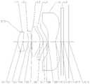
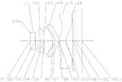
图1为示出根据本申请实施例1的摄像镜头的结构示意图;FIG. 1 is a schematic structural diagram illustrating a camera lens according to
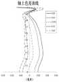
图2A示出了实施例1的摄像镜头的轴上色差曲线;2A shows the on-axis chromatic aberration curve of the imaging lens of
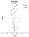
图2B示出了实施例1的摄像镜头的象散曲线;2B shows the astigmatism curve of the imaging lens of
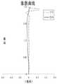
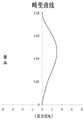
图2C示出了实施例1的摄像镜头的畸变曲线;FIG. 2C shows the distortion curve of the imaging lens of
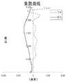
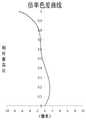
图2D示出了实施例1的摄像镜头的倍率色差曲线;FIG. 2D shows the magnification chromatic aberration curve of the imaging lens of
图3为示出根据本申请实施例2的摄像镜头的结构示意图;3 is a schematic structural diagram illustrating a camera lens according to
图4A示出了实施例2的摄像镜头的轴上色差曲线;4A shows the on-axis chromatic aberration curve of the imaging lens of
图4B示出了实施例2的摄像镜头的象散曲线;FIG. 4B shows the astigmatism curve of the imaging lens of
图4C示出了实施例2的摄像镜头的畸变曲线;FIG. 4C shows the distortion curve of the imaging lens of
图4D示出了实施例2的摄像镜头的倍率色差曲线;FIG. 4D shows the magnification chromatic aberration curve of the imaging lens of
图5为示出根据本申请实施例3的摄像镜头的结构示意图;FIG. 5 is a schematic structural diagram illustrating a camera lens according to
图6A示出了实施例3的摄像镜头的轴上色差曲线;6A shows the on-axis chromatic aberration curve of the imaging lens of
图6B示出了实施例3的摄像镜头的象散曲线;FIG. 6B shows the astigmatism curve of the imaging lens of
图6C示出了实施例3的摄像镜头的畸变曲线;FIG. 6C shows the distortion curve of the imaging lens of
图6D示出了实施例3的摄像镜头的倍率色差曲线;6D shows the magnification chromatic aberration curve of the imaging lens of
图7为示出根据本申请实施例4的摄像镜头的结构示意图;FIG. 7 is a schematic structural diagram illustrating a camera lens according to
图8A示出了实施例4的摄像镜头的轴上色差曲线;8A shows the on-axis chromatic aberration curve of the imaging lens of
图8B示出了实施例4的摄像镜头的象散曲线;FIG. 8B shows the astigmatism curve of the imaging lens of
图8C示出了实施例4的摄像镜头的畸变曲线;FIG. 8C shows the distortion curve of the imaging lens of
图8D示出了实施例4的摄像镜头的倍率色差曲线;8D shows the magnification chromatic aberration curve of the imaging lens of
图9为示出根据本申请实施例5的摄像镜头的结构示意图;FIG. 9 is a schematic structural diagram illustrating a camera lens according to
图10A示出了实施例5的摄像镜头的轴上色差曲线;10A shows the on-axis chromatic aberration curve of the imaging lens of
图10B示出了实施例5的摄像镜头的象散曲线;FIG. 10B shows the astigmatism curve of the imaging lens of
图10C示出了实施例5的摄像镜头的畸变曲线;FIG. 10C shows the distortion curve of the imaging lens of
图10D示出了实施例5的摄像镜头的倍率色差曲线;10D shows the magnification chromatic aberration curve of the imaging lens of
图11为示出根据本申请实施例6的摄像镜头的结构示意图;FIG. 11 is a schematic structural diagram illustrating a camera lens according to
图12A示出了实施例6的摄像镜头的轴上色差曲线;12A shows the on-axis chromatic aberration curve of the imaging lens of
图12B示出了实施例6的摄像镜头的象散曲线;FIG. 12B shows the astigmatism curve of the imaging lens of
图12C示出了实施例6的摄像镜头的畸变曲线;FIG. 12C shows the distortion curve of the imaging lens of
图12D示出了实施例6的摄像镜头的倍率色差曲线;12D shows the magnification chromatic aberration curve of the imaging lens of
图13为示出根据本申请实施例7的摄像镜头的结构示意图;FIG. 13 is a schematic diagram showing the structure of an imaging lens according to Embodiment 7 of the present application;
图14A示出了实施例7的摄像镜头的轴上色差曲线;14A shows the on-axis chromatic aberration curve of the imaging lens of Embodiment 7;
图14B示出了实施例7的摄像镜头的象散曲线;14B shows the astigmatism curve of the imaging lens of Embodiment 7;
图14C示出了实施例7的摄像镜头的畸变曲线;FIG. 14C shows the distortion curve of the imaging lens of Embodiment 7;
图14D示出了实施例7的摄像镜头的倍率色差曲线;14D shows the magnification chromatic aberration curve of the imaging lens of Embodiment 7;
图15为示出根据本申请实施例8的摄像镜头的结构示意图;FIG. 15 is a schematic diagram showing the structure of an imaging lens according to
图16A示出了实施例8的摄像镜头的轴上色差曲线;16A shows the on-axis chromatic aberration curve of the imaging lens of
图16B示出了实施例8的摄像镜头的象散曲线;FIG. 16B shows the astigmatism curve of the imaging lens of
图16C示出了实施例8的摄像镜头的畸变曲线;FIG. 16C shows the distortion curve of the imaging lens of
图16D示出了实施例8的摄像镜头的倍率色差曲线;16D shows the magnification chromatic aberration curve of the imaging lens of
具体实施方式Detailed ways
为了更好地理解本申请,将参考附图对本申请的各个方面做出更 详细的说明。应理解,这些详细说明只是对本申请的示例性实施方式 的描述,而非以任何方式限制本申请的范围。在说明书全文中,相同的 附图标号指代相同的元件。表述“和/或”包括相关联的所列项目中的一 个或多个的任何和全部组合。For a better understanding of the present application, various aspects of the present application will be described in more detail with reference to the accompanying drawings. It should be understood that these detailed descriptions are merely illustrative of exemplary embodiments of the present application and are not intended to limit the scope of the present application in any way. Throughout the specification, the same reference numerals refer to the same elements. The expression "and/or" includes any and all combinations of one or more of the associated listed items.
应理解的是,虽然用语第一、第二等在本文中可以用来描述各种元 件、部件、区域、层和/或段,但是这些元件、部件、区域、层和/或段不 应被这些用语限制。这些用语仅用于将一个元件、部件、区域、层或段 与另一个元件、部件、区域、层或段区分开。因此,在不背离本申请的 教导的情况下,下文中讨论的第一元件、第一部件、第一区域、第一层 或第一段可被称作第二元件、第二部件、第二区域、第二层或第二段。It will be understood that, although the terms first, second, etc. may be used herein to describe various elements, components, regions, layers and/or sections, these elements, components, regions, layers and/or sections should not be These terms are restricted. These terms are only used to distinguish one element, component, region, layer or section from another element, component, region, layer or section. Thus, a first element, component, region, layer or section discussed below could be termed a second element, component, region, or section without departing from the teachings of the present application. area, second level, or second segment.
在附图中,为了便于说明,已稍微夸大了透镜的厚度、尺寸和形状。 具体来讲,附图中所示的球面或非球面的形状通过示例的方式示出。即, 球面或非球面的形状不限于附图中示出的球面或非球面的形状。附图仅 为示例而并非严格按比例绘制。In the drawings, the thickness, size and shape of the lenses have been slightly exaggerated for convenience of explanation. In particular, the spherical or aspherical shapes shown in the figures are shown by way of example. That is, the shape of the spherical surface or the aspherical surface is not limited to the shape of the spherical surface or the aspherical surface shown in the drawings. The drawings are by way of example only and are not drawn strictly to scale.
还应理解的是,用语“包括”、“包括有”、“具有”、“包含”和/或“包 含有”,当在本说明书中使用时表示存在所陈述的特征、整体、步骤、操 作、元件和/或部件,但不排除存在或附加有一个或多个其它特征、整体、 步骤、操作、元件、部件和/或它们的组合。此外,当诸如“...中的至少 一个”的表述出现在所列特征的列表之后时,修饰整个所列特征,而不 是修饰列表中的单独元件。此外,当描述本申请的实施方式时,使用“可 以”表示“本申请的一个或多个实施方式”。并且,用语“示例性的”旨 在指代示例或举例说明。It will also be understood that the terms "comprising", "comprising", "having", "comprising" and/or "comprising" when used in this specification mean the presence of stated features, integers, steps, operations , elements and/or components, but do not preclude the presence or addition of one or more other features, integers, steps, operations, elements, components and/or combinations thereof. Furthermore, when an expression such as "at least one of" appears after a list of listed features, it modifies the entire listed feature and not the individual elements of the list. Additionally, the use of "may" when describing embodiments of the present application means "one or more embodiments of the present application." Also, the term "exemplary" is intended to refer to an example or illustration.
如在本文中使用的,用语“基本上”、“大约”以及类似的用语用作 表近似的用语,而不用作表程度的用语,并且旨在说明将由本领域普通 技术人员认识到的、测量值或计算值中的固有偏差。As used herein, the terms "substantially," "approximately," and similar terms are used as terms of approximation, not of degree, and are intended to describe measurements that would be recognized by those of ordinary skill in the art. Inherent bias in a value or calculated value.
除非另外限定,否则本文中使用的所有用语(包括技术用语和科学 用语)均具有与本申请所属领域普通技术人员的通常理解相同的含义。 还应理解的是,用语(例如在常用词典中定义的用语)应被解释为具有 与它们在相关技术的上下文中的含义一致的含义,并且将不被以理想化 或过度正式意义解释,除非本文中明确如此限定。Unless otherwise defined, all terms (including technical and scientific terms) used herein have the same meaning as commonly understood by one of ordinary skill in the art to which this application belongs. It should also be understood that terms (such as those defined in commonly used dictionaries) should be interpreted to have meanings consistent with their meanings in the context of the related art, and will not be interpreted in an idealized or overly formal sense, unless It is expressly so limited herein.
需要说明的是,在不冲突的情况下,本申请中的实施例及实施例 中的特征可以相互组合。下面将参考附图并结合实施例来详细说明本 申请。It should be noted that the embodiments in the present application and the features of the embodiments may be combined with each other under the condition of no conflict. The present application will be described in detail below with reference to the accompanying drawings and in conjunction with the embodiments.
以下结合具体实施例进一步描述本申请。The present application is further described below with reference to specific embodiments.
根据本申请示例性实施方式的摄像镜头具有总有效焦距f以及入 射瞳直径EPD,并可包括沿着光轴从物侧至像侧依次排列的第一透镜、 多个后续透镜以及感光元件。The imaging lens according to the exemplary embodiment of the present application has a total effective focal length f and an entrance pupil diameter EPD, and may include a first lens, a plurality of subsequent lenses, and a photosensitive element sequentially arranged along the optical axis from the object side to the image side.
在示例性实施方式中,第一透镜可具有正屈折力并且其物侧面可 为凸面。摄像镜头的总有效焦距f与摄像镜头的入射瞳直径EPD之间 可满足f/EPD≤2,例如,1.875≤f/EPD≤1.989。这可有利于加大通光 量,使系统具有大光圈优势,增强暗环境下的成像效果。摄像镜头的 总有效焦距f与感光元件的有效像素区域对角线长的一半ImgH之间 可满足ImgH/f>0.85,例如,0.997≤ImgH/f≤1.013;其中,感光器件 设置在成像面上。按照上述关系配置的摄像镜头,可在保证小型化的 同时提高视场角,并有效修正诸如轴上色差、象散及倍率色差等各类 像差,从而提升成像品质。In an exemplary embodiment, the first lens may have a positive refractive power and an object side surface thereof may be convex. The total effective focal length f of the imaging lens and the entrance pupil diameter EPD of the imaging lens may satisfy f/EPD≤2, for example, 1.875≤f/EPD≤1.989. This can help to increase the amount of light that passes through, giving the system the advantage of a large aperture and enhancing imaging in dark environments. The total effective focal length f of the camera lens and the half of the diagonal length of the effective pixel area of the photosensitive element ImgH can satisfy ImgH/f>0.85, for example, 0.997≤ImgH/f≤1.013; wherein, the photosensitive device is arranged on the imaging surface . The camera lens configured according to the above relationship can increase the field of view while ensuring miniaturization, and effectively correct various aberrations such as axial chromatic aberration, astigmatism and magnification chromatic aberration, thereby improving image quality.
在示例性实施方式中,多个后续透镜可包括具有负屈折力的第二 透镜。第一透镜和第二透镜在所述光轴上的间隔距离T12与第一透镜 的物侧面至摄像镜头的成像面的轴上距离TTL之间可满足0.08< T12/TTL<0.12,例如,0.089≤T12/TTL≤0.113。通过合理设置第一透 镜的物侧面至摄像镜头的成像面的轴上距离TTL,可将镜头总长约束 在较短的范围内,保证该系统的小型化,以便于在较薄的手机镜头中 使用。In an exemplary embodiment, the plurality of subsequent lenses may include a second lens having a negative refractive power. The separation distance T12 between the first lens and the second lens on the optical axis and the on-axis distance TTL from the object side of the first lens to the imaging plane of the camera lens may satisfy 0.08<T12/TTL<0.12, for example, 0.089 ≤T12/TTL≤0.113. By reasonably setting the on-axis distance TTL from the object side of the first lens to the imaging surface of the camera lens, the total length of the lens can be constrained within a short range to ensure the miniaturization of the system, so that it can be easily used in thin mobile phone lenses .
在示例性实施方式中,多个后续透镜还可包括位于所述第二透镜 与所述像侧之间的第三透镜。第三透镜可具有正屈折力,并且其像侧 面为凸面。在实践中,还可对各透镜之间的轴上间隔距离进行优化。 例如,第一透镜和第二透镜在光轴上的间隔距离T12与第二透镜和第 三透镜在光轴上的间隔距离T23可满足4<T12/T23<13.5,例如T12和 T23进一步可满足4.314≤T12/T23≤13.338。通过合理设置各透镜之 间的轴上间隔距离,可在保证使摄像镜头小型化的同时降低高级像差、 降低系统敏感性,从而提高成像品质。In an exemplary embodiment, the plurality of subsequent lenses may further include a third lens located between the second lens and the image side. The third lens may have a positive refractive power and be convex on its image side. In practice, the on-axis separation distance between the lenses can also be optimized. For example, the separation distance T12 between the first lens and the second lens on the optical axis and the separation distance T23 between the second lens and the third lens on the optical axis can satisfy 4<T12/T23<13.5, for example, T12 and T23 can further satisfy 4.314≤T12/T23≤13.338. By properly setting the on-axis distance between the lenses, it is possible to reduce advanced aberrations and system sensitivity while ensuring the miniaturization of the camera lens, thereby improving image quality.
第二透镜的有效焦距f2与第三透镜的有效焦距f3可满足 -5<f2/f3<-1.8,例如f2与f3进一步满足-4.505≤f2/f3≤-2.166。通过合 理地配置第二透镜的有效焦距f2和第三透镜的有效焦距f3的参数, 可实现广角功能。The effective focal length f2 of the second lens and the effective focal length f3 of the third lens may satisfy -5<f2/f3<-1.8, for example, f2 and f3 further satisfy -4.505≤f2/f3≤-2.166. By properly configuring the parameters of the effective focal length f2 of the second lens and the effective focal length f3 of the third lens, the wide-angle function can be realized.
在示例性实施方式中,多个后续透镜还可包括位于第三透镜与像 侧之间的第四透镜和第五透镜。第四透镜具有屈折力,其物侧面可为 凹面。第三透镜像侧面的曲率半径R6与第四透镜物侧面的曲率半径 R7可满足1.4<R6/R7<2.1,例如,1.453≤R6/R7≤2.009。通过合理配 置第三透镜像侧面的曲率半径R6和第四透镜物侧面的曲率半径R7可 保证光线入射角度的平缓,有助于修正系统整体像差。另外,可通过 合理设置第四透镜物侧面的曲率半径R7和第四透镜像侧面的曲率半 径R8对第四透镜的球差进行矫正,从而在保证该摄像镜头的成像质 量的同时降低主光线角度。第四透镜物侧面的曲率半径R7与第四透 镜像侧面的曲率半径R8可满足0.5<R7/R8<1.3,例如,0.657≤R7/R8 ≤1.21。In an exemplary embodiment, the plurality of subsequent lenses may further include a fourth lens and a fifth lens located between the third lens and the image side. The fourth lens has refractive power, and its object side can be concave. The curvature radius R6 of the image side surface of the third lens and the curvature radius R7 of the object side surface of the fourth lens may satisfy 1.4<R6/R7<2.1, for example, 1.453≤R6/R7≤2.009. By reasonably configuring the curvature radius R6 of the image side of the third lens and the curvature radius R7 of the object side of the fourth lens, the incident angle of the light can be guaranteed to be gentle, which is helpful to correct the overall aberration of the system. In addition, the spherical aberration of the fourth lens can be corrected by reasonably setting the curvature radius R7 of the object side of the fourth lens and the curvature radius R8 of the image side of the fourth lens, thereby reducing the chief ray angle while ensuring the imaging quality of the camera lens. . The curvature radius R7 of the object side surface of the fourth lens and the curvature radius R8 of the fourth lens image side surface may satisfy 0.5<R7/R8<1.3, for example, 0.657≤R7/R8≤1.21.
此外,第三透镜的有效焦距f3与第四透镜的有效焦距f4可满足 |f3/f4|<0.8,例如f3和f4可进一步满足0.16≤|f3/f4|≤0.68。第三透镜 像侧面和光轴的交点至第一透镜物侧面的有效半径顶点之间的轴上距 离SAG32与第四透镜物侧面和光轴的交点至第一透镜物侧面的有效 半径顶点之间的轴上距离SAG41可满足0.5<SAG32/SAG41<1,例如, 0.615≤SAG32/SAG41≤0.91。In addition, the effective focal length f3 of the third lens and the effective focal length f4 of the fourth lens may satisfy |f3/f4|<0.8, for example, f3 and f4 may further satisfy 0.16≤|f3/f4|≤0.68. The on-axis distance SAG32 between the intersection of the image side and the optical axis of the third lens to the apex of the effective radius of the object side of the first lens and the axis between the intersection of the object side and the optical axis of the fourth lens to the apex of the effective radius of the object side of the first lens The upper distance SAG41 may satisfy 0.5<SAG32/SAG41<1, for example, 0.615≤SAG32/SAG41≤0.91.
第五透镜具有屈折力,其像侧面可为凹面。在应用中,可对各透 镜的厚度进行优化。例如,第三透镜在光轴上的中心厚度CT3与第五 透镜在光轴上的中心厚度CT5可满足0.8<CT3/CT5<1.5,例如,0.926 ≤CT3/CT5≤1.276。通过合理地配置第三透镜在光轴上的中心厚度 CT3与第五透镜在光轴上的中心厚度CT5可在保证小型化的同时提高 视场角,实现广角功能。The fifth lens has refractive power, and its image side surface can be concave. In application, the thickness of each lens can be optimized. For example, the central thickness CT3 of the third lens on the optical axis and the central thickness CT5 of the fifth lens on the optical axis may satisfy 0.8<CT3/CT5<1.5, for example, 0.926≤CT3/CT5≤1.276. By properly arranging the central thickness CT3 of the third lens on the optical axis and the central thickness CT5 of the fifth lens on the optical axis, the field of view can be improved while ensuring miniaturization, and the wide-angle function can be realized.
在具体应用中,还可将本申请的摄像镜头的最大视场角FOV设置 为FOV>85°,从而通过合理分配各透镜的光焦度和面型来有效地增 加摄像镜头的视角,进而在保证镜头的小型化的同时提高镜头的成像 质量。In specific applications, the maximum field of view FOV of the camera lens of the present application can also be set to FOV>85°, so that the angle of view of the camera lens can be effectively increased by rationally distributing the focal power and surface shape of each lens. Ensuring the miniaturization of the lens while improving the imaging quality of the lens.
根据本申请的上述实施方式的摄像镜头可采用多片镜片,例如上 文所述的五片。通过合理分配各透镜的光焦度、面型、各透镜之间的 轴上间距等,可有效增加摄像镜头的视角,保证镜头的小型化并提高 成像质量,从而使得摄像镜头更有利于生产加工并且可适用于便携式 电子产品。在本申请的实施方式中,各透镜的镜面中的至少一个为非 球面镜面。非球面透镜的特点是:从透镜中心到周边曲率是连续变化 的。与从透镜中心到周边有一定曲率的球面透镜不同,非球面透镜具 有更佳的曲率半径特性,具有改善歪曲像差及改善像散像差的优点, 能够使得视野变得更大而真实。采用非球面透镜后,能够尽可能地消除在成像的时候出现的像差,从而改善成像质量。The imaging lens according to the above-mentioned embodiments of the present application may employ a plurality of lenses, such as the above-mentioned five lenses. By rationally distributing the power of each lens, the surface shape, and the on-axis distance between each lens, the angle of view of the camera lens can be effectively increased, the miniaturization of the lens can be ensured, and the imaging quality can be improved, thereby making the camera lens more conducive to production and processing. And can be applied to portable electronic products. In the embodiment of the present application, at least one of the mirror surfaces of each lens is an aspherical mirror surface. Aspherical lenses are characterized by a continuous change in curvature from the center of the lens to the periphery. Different from spherical lenses with a certain curvature from the center of the lens to the periphery, aspherical lenses have better curvature radius characteristics, and have the advantages of improving distortion and astigmatism, and can make the field of view larger and more real. After the aspherical lens is used, the aberration that occurs during imaging can be eliminated as much as possible, thereby improving the imaging quality.
然而,本领域的技术人员应当理解,在未背离本申请要求保护的 技术方案的情况下,可改变镜头的构成数量,来获得下面描述的各个 结果和优点。例如,虽然在实施方式中以五个透镜为例进行了描述, 但是该摄像镜头不限于包括五个透镜。如果需要,该摄像镜头还可包 括其它数量的透镜。However, those skilled in the art should understand that, without departing from the technical solutions claimed in the present application, the number of lenses can be changed to obtain the various results and advantages described below. For example, although five lenses are described as an example in the embodiment, the imaging lens is not limited to including five lenses. If desired, the camera lens may also include other numbers of lenses.
下面参照图1至图16D进一步描述可适用于上述实施方式的摄像 镜头的具体实施例。Specific examples of the imaging lens applicable to the above-described embodiments are further described below with reference to Figs. 1 to 16D.
实施例1Example 1
以下参照图1至图2D描述根据本申请实施例1的摄像镜头。The imaging lens according to
如图1所示,摄像镜头沿着光轴包括从物侧至成像侧依序排列的 五个透镜L1-L5。第一透镜L1具有物侧面S1和像侧面S2;第二透镜 L2具有物侧面S3和像侧面S4;第三透镜L3具有物侧面S5和像侧面 S6;第四透镜L4具有物侧面S7和像侧面S8;第五透镜L5具有物侧面S9和像侧面S10。该摄像镜头还可包括光阑(未示出)以及用于滤 除红外光的具有物侧面S11和像侧面S12的滤光片L6。在本实施例的 摄像镜头中,还可设置有光圈STO以调解进光量。来自物体的光依序 穿过各表面S1至S12并最终成像在成像表面S13上。As shown in Fig. 1, the imaging lens includes five lenses L1-L5 sequentially arranged from the object side to the imaging side along the optical axis. The first lens L1 has an object side S1 and an image side S2; the second lens L2 has an object side S3 and an image side S4; the third lens L3 has an object side S5 and an image side S6; the fourth lens L4 has an object side S7 and an image side S8; the fifth lens L5 has an object side S9 and an image side S10. The imaging lens may further include a diaphragm (not shown) and a filter L6 having an object side surface S11 and an image side surface S12 for filtering out infrared light. In the imaging lens of this embodiment, an aperture STO may also be provided to adjust the amount of incoming light. The light from the object sequentially passes through each of the surfaces S1 to S12 and is finally imaged on the imaging surface S13.
表1示出了实施例1的摄像镜头的各透镜的表面类型、曲率半径、 厚度、材料及圆锥系数。Table 1 shows the surface type, curvature radius, thickness, material, and cone coefficient of each lens of the imaging lens of Example 1.


表1Table 1
由表1可得,第三透镜L3像侧面的曲率半径R6与第四透镜L4 物侧面的曲率半径R7满足R6/R7=1.453。第四透镜L4物侧面的曲率 半径R7与第四透镜L4像侧面的曲率半径R8满足R7/R8=0.987。As can be seen from Table 1, the curvature radius R6 of the image side surface of the third lens L3 and the curvature radius R7 of the object side surface of the fourth lens L4 satisfy R6/R7=1.453. The curvature radius R7 of the object side surface of the fourth lens L4 and the curvature radius R8 of the image side surface of the fourth lens L4 satisfy R7/R8=0.987.
本实施例采用了5片透镜作为示例,通过合理分配个镜片的焦距 与面型,有效扩大视场角,缩短了镜头总长度,保证镜头的广角化与 小型化;同时校正各类像差,提高了镜头的解析度与成像品质。各非 球面面型由以下公式限定:This embodiment uses 5 lenses as an example. By rationally distributing the focal length and surface shape of each lens, the angle of view is effectively expanded, the total length of the lens is shortened, and the wide-angle and miniaturization of the lens is ensured; at the same time, various aberrations are corrected, Improve the resolution and imaging quality of the lens. Each aspheric surface shape is defined by the following formula:

其中,c为非球面的近轴曲率,即为上表1中曲率半径的倒数,h 为非球面上任一点距主光轴的高度,k为圆锥系数,Ai是非球面第i-th 阶的修正系数。下表2示出了实施例1中可用于各镜面S1-S10的高次 项系数A4、A6、A8、A10、A12和A16。Among them, c is the paraxial curvature of the aspheric surface, which is the reciprocal of the curvature radius in Table 1 above, h is the height of any point on the aspheric surface from the main optical axis, k is the conic coefficient, and Ai is the correction of the i-th order of the aspheric surface coefficient. Table 2 below shows the higher order coefficients A4 , A6 , A8 , A10 , A12 , and A16 available for each of the mirror surfaces S1 - S10 in Example 1.
表2Table 2
以下所示出的表3给出实施例1的各透镜的有效焦距f1至f5、摄 像镜头的总有效焦距f以及摄像镜头的总长度TTL。摄像镜头的最大 视场角FOV可设置为FOV=91.293°。Table 3 shown below gives the effective focal lengths f1 to f5 of the respective lenses of
表3table 3
根据表3,第二透镜L2的有效焦距f2与第三透镜L3的有效焦距 f3满足f2/f3=-2.166。第三透镜L3的有效焦距f3与所述第四透镜L4 的有效焦距f4满足|f3/f4|=0.251。According to Table 3, the effective focal length f2 of the second lens L2 and the effective focal length f3 of the third lens L3 satisfy f2/f3=-2.166. The effective focal length f3 of the third lens L3 and the effective focal length f4 of the fourth lens L4 satisfy |f3/f4|=0.251.
在该实施例中,摄像镜头的总有效焦距f与摄像镜头的入射瞳直 径EPD满足f/EPD=1.949。摄像镜头的总有效焦距f与感光元件的有 效像素区域对角线长的一半ImgH满足ImgH/f=1.013。第一透镜L1和 第二透镜L2在光轴上的间隔距离T12与从第一透镜L1的物侧面至摄 像镜头的成像面的轴上距离TTL满足T12/TTL=0.102。第一透镜L1 和第二透镜L2在光轴上的间隔距离T12与第二透镜L2和第三透镜 L3在光轴上的间隔距离T23满足T12/T23=8.242。第三透镜L3像侧 面和光轴的交点至第一透镜L1物侧面的有效半径顶点之间的轴上距 离SAG32与第四透镜L4物侧面和光轴的交点至第一透镜L1物侧面 的有效半径顶点之间的轴上距离SAG41满足SAG32/SAG41=0.615。 第三透镜L3在光轴上的中心厚度CT3与第五透镜L5在光轴上的中心 厚度CT5满足CT3/CT5=1.105。In this embodiment, the total effective focal length f of the imaging lens and the entrance pupil diameter EPD of the imaging lens satisfy f/EPD=1.949. The total effective focal length f of the imaging lens and the half of the diagonal length of the effective pixel area of the photosensitive element ImgH satisfy ImgH/f=1.013. The separation distance T12 between the first lens L1 and the second lens L2 on the optical axis and the axial distance TTL from the object side of the first lens L1 to the imaging plane of the imaging lens satisfy T12/TTL=0.102. The separation distance T12 between the first lens L1 and the second lens L2 on the optical axis and the separation distance T23 between the second lens L2 and the third lens L3 on the optical axis satisfy T12/T23=8.242. The on-axis distance SAG32 between the intersection of the image side and the optical axis of the third lens L3 to the apex of the effective radius of the object side of the first lens L1 and the intersection of the object side and the optical axis of the fourth lens L4 to the apex of the effective radius of the object side of the first lens L1 The on-axis distance SAG41 between them satisfies SAG32/SAG41=0.615. The center thickness CT3 of the third lens L3 on the optical axis and the center thickness CT5 of the fifth lens L5 on the optical axis satisfy CT3/CT5=1.105.
图2A示出了实施例1的摄像镜头的轴上色差曲线,其表示不同 波长的光线经由光学系统后的会聚焦点偏离。图2B示出了实施例1 的摄像镜头的象散曲线,其表示子午像面弯曲和弧矢像面弯曲。图2C 示出了实施例1的摄像镜头的畸变曲线,其表示不同视角情况下的畸 变大小值。图2D示出了实施例1的摄像镜头的倍率色差曲线,其表 示光线经由光学成像系统后在成像面上的不同的像高的偏差。根据图 2A至图2D可知,实施例1所给出的摄像镜头的能够实现良好的成像 品质。Fig. 2A shows the on-axis chromatic aberration curve of the imaging lens of
实施例2Example 2
以下参照图3至图4D描述了根据本申请实施例2的摄像镜头。 在本实施例及以下实施例中,为简洁起见,将省略部分与实施例1相 似的描述。图3示出了根据本申请实施例2的摄像镜头的结构示意图。The imaging lens according to
如图3所示,摄像镜头沿着光轴包括从物侧至成像侧依序排列的 五个透镜L1-L5。第一透镜L1具有物侧面S1和像侧面S2;第二透镜 L2具有物侧面S3和像侧面S4;第三透镜L3具有物侧面S5和像侧面 S6;第四透镜L4具有物侧面S7和像侧面S8;第五透镜L5具有物侧面S9和像侧面S10。该摄像镜头还可包括光阑(未示出)以及用于滤 除红外光的具有物侧面S11和像侧面S12的滤光片L6。在本实施例的 摄像镜头中,还可设置有光圈STO以调解进光量。来自物体的光依序 穿过各表面S1至S12并最终成像在成像表面S13上。As shown in Fig. 3, the imaging lens includes five lenses L1-L5 arranged in order from the object side to the imaging side along the optical axis. The first lens L1 has an object side S1 and an image side S2; the second lens L2 has an object side S3 and an image side S4; the third lens L3 has an object side S5 and an image side S6; the fourth lens L4 has an object side S7 and an image side S8; the fifth lens L5 has an object side S9 and an image side S10. The imaging lens may further include a diaphragm (not shown) and a filter L6 having an object side surface S11 and an image side surface S12 for filtering out infrared light. In the imaging lens of this embodiment, an aperture STO may also be provided to adjust the amount of incoming light. The light from the object sequentially passes through each of the surfaces S1 to S12 and is finally imaged on the imaging surface S13.
表4示出了实施例2的摄像镜头的各透镜的表面类型、曲率半径、 厚度、材料及圆锥系数。表5示出了实施例2中各镜面的高次项系数。 表6示出了实施例2的各透镜的有效焦距f1至f5、光学成像系统的总 有效焦距f以及摄像透镜的总长度TTL。Table 4 shows the surface type, curvature radius, thickness, material, and cone coefficient of each lens of the imaging lens of Example 2. Table 5 shows the coefficients of higher-order terms of each mirror surface in Example 2. Table 6 shows the effective focal lengths f1 to f5 of the respective lenses of
表4Table 4

表6Table 6
图4A示出了实施例2的摄像镜头的轴上色差曲线,其表示不同 波长的光线经由光学系统后的会聚焦点偏离。图4B示出了实施例2 的摄像镜头的象散曲线,其表示子午像面弯曲和弧矢像面弯曲。图4C 示出了实施例2的摄像镜头的畸变曲线,其表示不同视角情况下的畸 变大小值。图4D示出了实施例2的摄像镜头的倍率色差曲线,其表 示光线经由光学成像系统后在成像面上的不同的像高的偏差。根据图 4A至图4D可知,实施例2所给出的摄像镜头的能够实现良好的成像 品质。Fig. 4A shows the on-axis chromatic aberration curve of the imaging lens of Example 2, which represents the deviation of the confocal point of light of different wavelengths after passing through the optical system. FIG. 4B shows the astigmatism curve of the imaging lens of
实施例3Example 3
以下参照图5至图6D描述了根据本申请实施例3的摄像镜头。 图5示出了根据本申请实施例3的摄像镜头的结构示意图。The imaging lens according to
如图5所示,摄像镜头沿着光轴包括从物侧至成像侧依序排列的 五个透镜L1-L5。第一透镜L1具有物侧面S1和像侧面S2;第二透镜 L2具有物侧面S3和像侧面S4;第三透镜L3具有物侧面S5和像侧面 S6;第四透镜L4具有物侧面S7和像侧面S8;第五透镜L5具有物侧面S9和像侧面S10。该摄像镜头还可包括光阑(未示出)以及用于滤 除红外光的具有物侧面S11和像侧面S12的滤光片L6。在本实施例的 摄像镜头中,还可设置有光圈STO以调解进光量。来自物体的光依序 穿过各表面S1至S12并最终成像在成像表面S13上。As shown in Fig. 5, the imaging lens includes five lenses L1-L5 arranged in order from the object side to the imaging side along the optical axis. The first lens L1 has an object side S1 and an image side S2; the second lens L2 has an object side S3 and an image side S4; the third lens L3 has an object side S5 and an image side S6; the fourth lens L4 has an object side S7 and an image side S8; the fifth lens L5 has an object side S9 and an image side S10. The imaging lens may further include a diaphragm (not shown) and a filter L6 having an object side surface S11 and an image side surface S12 for filtering out infrared light. In the imaging lens of this embodiment, an aperture STO may also be provided to adjust the amount of incoming light. The light from the object sequentially passes through each of the surfaces S1 to S12 and is finally imaged on the imaging surface S13.
表7示出了实施例3的摄像镜头的各透镜的表面类型、曲率半径、 厚度、材料及圆锥系数。表8示出了实施例3中各镜面的高次项系数。 表9示出了实施例3的各透镜的有效焦距f1至f5、光学成像系统的总 有效焦距f以及摄像透镜的总长度TTL。Table 7 shows the surface type, curvature radius, thickness, material, and cone coefficient of each lens of the imaging lens of Example 3. Table 8 shows the higher-order term coefficients of each mirror surface in Example 3. Table 9 shows the effective focal lengths f1 to f5 of the respective lenses of


表7Table 7
表8Table 8
表9Table 9
图6A示出了实施例3的摄像镜头的轴上色差曲线,其表示不同 波长的光线经由光学系统后的会聚焦点偏离。图6B示出了实施例3 的摄像镜头的象散曲线,其表示子午像面弯曲和弧矢像面弯曲。图6C 示出了实施例3的摄像镜头的畸变曲线,其表示不同视角情况下的畸 变大小值。图6D示出了实施例3的摄像镜头的倍率色差曲线,其表 示光线经由光学成像系统后在成像面上的不同的像高的偏差。根据图 6A至图6D可知,实施例3所给出的摄像镜头的能够实现良好的成像 品质。Fig. 6A shows the on-axis chromatic aberration curve of the imaging lens of Example 3, which represents the deviation of the converging point of light of different wavelengths after passing through the optical system. FIG. 6B shows the astigmatism curve of the imaging lens of
实施例4Example 4
以下参照图7至图8D描述了根据本申请实施例4的摄像镜头。 图7示出了根据本申请实施例4的摄像镜头的结构示意图。The imaging lens according to
如图7所示,摄像镜头沿着光轴包括从物侧至成像侧依序排列的 五个透镜L1-L5。第一透镜L1具有物侧面S1和像侧面S2;第二透镜 L2具有物侧面S3和像侧面S4;第三透镜L3具有物侧面S5和像侧面 S6;第四透镜L4具有物侧面S7和像侧面S8;第五透镜L5具有物侧面S9和像侧面S10。该摄像镜头还可包括光阑(未示出)以及用于滤 除红外光的具有物侧面S11和像侧面S12的滤光片L6。在本实施例的 摄像镜头中,还可设置有光圈STO以调解进光量。来自物体的光依序 穿过各表面S1至S12并最终成像在成像表面S13上。As shown in Fig. 7, the imaging lens includes five lenses L1-L5 sequentially arranged from the object side to the imaging side along the optical axis. The first lens L1 has an object side S1 and an image side S2; the second lens L2 has an object side S3 and an image side S4; the third lens L3 has an object side S5 and an image side S6; the fourth lens L4 has an object side S7 and an image side S8; the fifth lens L5 has an object side S9 and an image side S10. The imaging lens may further include a diaphragm (not shown) and a filter L6 having an object side surface S11 and an image side surface S12 for filtering out infrared light. In the imaging lens of this embodiment, an aperture STO may also be provided to adjust the amount of incoming light. The light from the object sequentially passes through each of the surfaces S1 to S12 and is finally imaged on the imaging surface S13.
表10示出了实施例4的摄像镜头的各透镜的表面类型、曲率半径、 厚度、材料及圆锥系数。表11示出了实施例4中各镜面的高次项系数。 表12示出了实施例4的各透镜的有效焦距f1至f5、光学成像系统的 总有效焦距f以及摄像透镜的总长度TTL。Table 10 shows the surface type, curvature radius, thickness, material, and conic coefficient of each lens of the imaging lens of Example 4. Table 11 shows the higher-order term coefficients of each mirror surface in Example 4. Table 12 shows the effective focal lengths f1 to f5 of the respective lenses of
表10Table 10


表11Table 11
表12Table 12
图8A示出了实施例4的摄像镜头的轴上色差曲线,其表示不同 波长的光线经由光学系统后的会聚焦点偏离。图8B示出了实施例4 的摄像镜头的象散曲线,其表示子午像面弯曲和弧矢像面弯曲。图8C 示出了实施例4的摄像镜头的畸变曲线,其表示不同视角情况下的畸 变大小值。图8D示出了实施例4的摄像镜头的倍率色差曲线,其表 示光线经由光学成像系统后在成像面上的不同的像高的偏差。根据图 8A至图8D可知,实施例4所给出的摄像镜头的能够实现良好的成像 品质。Fig. 8A shows the on-axis chromatic aberration curve of the imaging lens of Example 4, which represents the deviation of the converging point of light of different wavelengths after passing through the optical system. FIG. 8B shows the astigmatism curve of the imaging lens of Example 4, which represents the meridional curvature of the image plane and the sagittal curvature of the image plane. Fig. 8C shows the distortion curve of the imaging lens of
实施例5Example 5
以下参照图9至图10D描述了根据本申请实施例5的摄像镜头。 图9示出了根据本申请实施例5的摄像镜头的结构示意图。The imaging lens according to
如图9所示,摄像镜头沿着光轴包括从物侧至成像侧依序排列的 五个透镜L1-L5。第一透镜L1具有物侧面S1和像侧面S2;第二透镜 L2具有物侧面S3和像侧面S4;第三透镜L3具有物侧面S5和像侧面 S6;第四透镜L4具有物侧面S7和像侧面S8;第五透镜L5具有物侧面S9和像侧面S10。该摄像镜头还可包括光阑(未示出)以及用于滤 除红外光的具有物侧面S11和像侧面S12的滤光片L6。在本实施例的 摄像镜头中,还可设置有光圈STO以调解进光量。来自物体的光依序 穿过各表面S1至S12并最终成像在成像表面S13上。As shown in Fig. 9, the imaging lens includes five lenses L1-L5 arranged in order from the object side to the imaging side along the optical axis. The first lens L1 has an object side S1 and an image side S2; the second lens L2 has an object side S3 and an image side S4; the third lens L3 has an object side S5 and an image side S6; the fourth lens L4 has an object side S7 and an image side S8; the fifth lens L5 has an object side S9 and an image side S10. The imaging lens may further include a diaphragm (not shown) and a filter L6 having an object side surface S11 and an image side surface S12 for filtering out infrared light. In the imaging lens of this embodiment, an aperture STO may also be provided to adjust the amount of incoming light. The light from the object sequentially passes through each of the surfaces S1 to S12 and is finally imaged on the imaging surface S13.
表13示出了实施例4的摄像镜头的各透镜的表面类型、曲率半径、 厚度、材料及圆锥系数。表14示出了实施例4中各镜面的高次项系数。 表15示出了实施例4的各透镜的有效焦距f1至f5、光学成像系统的 总有效焦距f以及摄像透镜的总长度TTL。Table 13 shows the surface type, curvature radius, thickness, material, and cone coefficient of each lens of the imaging lens of Example 4. Table 14 shows the higher-order term coefficients of each mirror surface in Example 4. Table 15 shows the effective focal lengths f1 to f5 of the respective lenses of
表13Table 13
表14Table 14
表15Table 15
图10A示出了实施例5的摄像镜头的轴上色差曲线,其表示不同 波长的光线经由光学系统后的会聚焦点偏离。图10B示出了实施例5 的摄像镜头的象散曲线,其表示子午像面弯曲和弧矢像面弯曲。图10C 示出了实施例5的摄像镜头的畸变曲线,其表示不同视角情况下的畸 变大小值。图10D示出了实施例5的摄像镜头的倍率色差曲线,其表 示光线经由光学成像系统后在成像面上的不同的像高的偏差。根据图 10A至图10D可知,实施例5所给出的摄像镜头的能够实现良好的成 像品质。Fig. 10A shows the on-axis chromatic aberration curve of the imaging lens of Example 5, which represents the deviation of the confocal point of light of different wavelengths after passing through the optical system. FIG. 10B shows the astigmatism curve of the imaging lens of Example 5, which represents the meridional curvature of the image plane and the sagittal curvature of the image plane. Fig. 10C shows the distortion curve of the imaging lens of
实施例6Example 6
以下参照图11至图12D描述了根据本申请实施例6的摄像镜头。 图11示出了根据本申请实施例6的摄像镜头的结构示意图。The imaging lens according to
如图11所示,摄像镜头沿着光轴包括从物侧至成像侧依序排列的 五个透镜L1-L5。第一透镜L1具有物侧面S1和像侧面S2;第二透镜 L2具有物侧面S3和像侧面S4;第三透镜L3具有物侧面S5和像侧面 S6;第四透镜L4具有物侧面S7和像侧面S8;第五透镜L5具有物侧 面S9和像侧面S10。该摄像镜头还可包括光阑(未示出)以及用于滤 除红外光的具有物侧面S11和像侧面S12的滤光片L6。在本实施例的 摄像镜头中,还可设置有光圈STO以调解进光量。来自物体的光依序 穿过各表面S1至S12并最终成像在成像表面S13上。As shown in Fig. 11, the imaging lens includes five lenses L1-L5 arranged in order from the object side to the imaging side along the optical axis. The first lens L1 has an object side S1 and an image side S2; the second lens L2 has an object side S3 and an image side S4; the third lens L3 has an object side S5 and an image side S6; the fourth lens L4 has an object side S7 and an image side S8; the fifth lens L5 has an object side S9 and an image side S10. The imaging lens may further include a diaphragm (not shown) and a filter L6 having an object side surface S11 and an image side surface S12 for filtering out infrared light. In the imaging lens of this embodiment, an aperture STO may also be provided to adjust the amount of incoming light. The light from the object sequentially passes through each of the surfaces S1 to S12 and is finally imaged on the imaging surface S13.
表16示出了实施例6的摄像镜头的各透镜的表面类型、曲率半径、 厚度、材料及圆锥系数。表17示出了实施例6中各镜面的高次项系数。 表18示出了实施例6的各透镜的有效焦距f1至f5、光学成像系统的 总有效焦距f以及摄像透镜的总长度TTL。Table 16 shows the surface type, curvature radius, thickness, material, and cone coefficient of each lens of the imaging lens of Example 6. Table 17 shows the higher-order term coefficients of each mirror surface in Example 6. Table 18 shows the effective focal lengths f1 to f5 of the respective lenses of


表16Table 16
表17Table 17
表18Table 18
图12A示出了实施例6的摄像镜头的轴上色差曲线,其表示不同 波长的光线经由光学系统后的会聚焦点偏离。图12B示出了实施例6 的摄像镜头的象散曲线,其表示子午像面弯曲和弧矢像面弯曲。图12C 示出了实施例6的摄像镜头的畸变曲线,其表示不同视角情况下的畸 变大小值。图12D示出了实施例6的摄像镜头的倍率色差曲线,其表 示光线经由光学成像系统后在成像面上的不同的像高的偏差。根据图 12A至图12D可知,实施例6所给出的摄像镜头的能够实现良好的成 像品质。Fig. 12A shows the on-axis chromatic aberration curve of the imaging lens of Example 6, which represents the deviation of the focal point of light of different wavelengths after passing through the optical system. FIG. 12B shows the astigmatism curve of the imaging lens of Example 6, which represents the meridional curvature of the image plane and the sagittal curvature of the image plane. Fig. 12C shows the distortion curve of the imaging lens of
实施例7Example 7
以下参照图13至图14D描述了根据本申请实施例7的摄像镜头。 图13示出了根据本申请实施例7的摄像镜头的结构示意图。The imaging lens according to Embodiment 7 of the present application is described below with reference to FIGS. 13 to 14D . FIG. 13 shows a schematic structural diagram of an imaging lens according to Embodiment 7 of the present application.
如图13所示,摄像镜头沿着光轴包括从物侧至成像侧依序排列的 五个透镜L1-L5。第一透镜L1具有物侧面S1和像侧面S2;第二透镜 L2具有物侧面S3和像侧面S4;第三透镜L3具有物侧面S5和像侧面 S6;第四透镜L4具有物侧面S7和像侧面S8;第五透镜L5具有物侧 面S9和像侧面S10。该摄像镜头还可包括光阑(未示出)以及用于滤 除红外光的具有物侧面S11和像侧面S12的滤光片L6。在本实施例的 摄像镜头中,还可设置有光圈STO以调解进光量。来自物体的光依序 穿过各表面S1至S12并最终成像在成像表面S13上。As shown in Fig. 13, the imaging lens includes five lenses L1-L5 arranged in order from the object side to the imaging side along the optical axis. The first lens L1 has an object side S1 and an image side S2; the second lens L2 has an object side S3 and an image side S4; the third lens L3 has an object side S5 and an image side S6; the fourth lens L4 has an object side S7 and an image side S8; the fifth lens L5 has an object side S9 and an image side S10. The imaging lens may further include a diaphragm (not shown) and a filter L6 having an object side surface S11 and an image side surface S12 for filtering out infrared light. In the imaging lens of this embodiment, an aperture STO may also be provided to adjust the amount of incoming light. The light from the object sequentially passes through each of the surfaces S1 to S12 and is finally imaged on the imaging surface S13.
表19示出了实施例7的摄像镜头的各透镜的表面类型、曲率半径、 厚度、材料及圆锥系数。表20示出了实施例7中各镜面的高次项系数。 表21示出了实施例7的各透镜的有效焦距f1至f5、光学成像系统的 总有效焦距f以及摄像透镜的总长度TTL。Table 19 shows the surface type, curvature radius, thickness, material, and cone coefficient of each lens of the imaging lens of Example 7. Table 20 shows the higher-order term coefficients of each mirror surface in Example 7. Table 21 shows the effective focal lengths f1 to f5 of the respective lenses of Embodiment 7, the total effective focal length f of the optical imaging system, and the total length TTL of the imaging lens.
表19Table 19


表20Table 20
表21Table 21
图14A示出了实施例7的摄像镜头的轴上色差曲线,其表示不同 波长的光线经由光学系统后的会聚焦点偏离。图14B示出了实施例7 的摄像镜头的象散曲线,其表示子午像面弯曲和弧矢像面弯曲。图14C 示出了实施例7的摄像镜头的畸变曲线,其表示不同视角情况下的畸 变大小值。图14D示出了实施例7的摄像镜头的倍率色差曲线,其表 示光线经由光学成像系统后在成像面上的不同的像高的偏差。根据图 14A至图14D可知,实施例7所给出的摄像镜头的能够实现良好的成 像品质。Fig. 14A shows the on-axis chromatic aberration curve of the imaging lens of Example 7, which represents the deviation of the converging point of light of different wavelengths after passing through the optical system. FIG. 14B shows the astigmatism curve of the imaging lens of Example 7, which represents the meridional curvature of the image plane and the sagittal curvature of the image plane. Fig. 14C shows the distortion curve of the imaging lens of Embodiment 7, which represents the magnitude of the distortion under different viewing angles. Fig. 14D shows the magnification chromatic aberration curve of the imaging lens of Example 7, which represents the deviation of different image heights on the imaging plane after light passes through the optical imaging system. 14A to 14D, it can be seen that the imaging lens provided in Embodiment 7 can achieve good imaging quality.
实施例8Example 8
以下参照图15至图16D描述了根据本申请实施例8的摄像镜头。 图15示出了根据本申请实施例8的摄像镜头的结构示意图。The imaging lens according to
如图15所示,摄像镜头沿着光轴包括从物侧至成像侧依序排列的 五个透镜L1-L5。第一透镜L1具有物侧面S1和像侧面S2;第二透镜 L2具有物侧面S3和像侧面S4;第三透镜L3具有物侧面S5和像侧面 S6;第四透镜L4具有物侧面S7和像侧面S8;第五透镜L5具有物侧 面S9和像侧面S10。该摄像镜头还可包括光阑(未示出)以及用于滤 除红外光的具有物侧面S11和像侧面S12的滤光片L6。在本实施例的 摄像镜头中,还可设置有光圈STO以调解进光量。来自物体的光依序 穿过各表面S1至S12并最终成像在成像表面S13上。As shown in Fig. 15, the imaging lens includes five lenses L1-L5 arranged in order from the object side to the imaging side along the optical axis. The first lens L1 has an object side S1 and an image side S2; the second lens L2 has an object side S3 and an image side S4; the third lens L3 has an object side S5 and an image side S6; the fourth lens L4 has an object side S7 and an image side S8; the fifth lens L5 has an object side S9 and an image side S10. The imaging lens may further include a diaphragm (not shown) and a filter L6 having an object side surface S11 and an image side surface S12 for filtering out infrared light. In the imaging lens of this embodiment, an aperture STO may also be provided to adjust the amount of incoming light. The light from the object sequentially passes through each of the surfaces S1 to S12 and is finally imaged on the imaging surface S13.
表22示出了实施例8的摄像镜头的各透镜的表面类型、曲率半径、 厚度、材料及圆锥系数。表23示出了实施例8中各镜面的高次项系数。 表24示出了实施例8的各透镜的有效焦距f1至f5、光学成像系统的 总有效焦距f以及摄像透镜的总长度TTL。Table 22 shows the surface type, curvature radius, thickness, material, and cone coefficient of each lens of the imaging lens of Example 8. Table 23 shows the higher-order term coefficients of each mirror surface in Example 8. Table 24 shows the effective focal lengths f1 to f5 of the respective lenses of
表22Table 22
表23Table 23
表24Table 24
图16A示出了实施例8的摄像镜头的畸变曲线,其表示不同视角情况下的畸变大小值。图16D示出了实施例8的摄像镜头的倍率色差曲线,其表示光线经由光学成像系统后在成像面上的不同的像高的偏差。根据图 16A至图16D可知,实施例8所给出的摄像镜头的能够实现良好的成像品质。FIG. 16A shows the distortion curve of the imaging lens of
综上,实施例1至实施例8分别满足以下表25所示的关系。In conclusion, Examples 1 to 8 satisfy the relationships shown in Table 25 below, respectively.
表25Table 25
本申请还提供一种摄像装置,其感光元件可以是感光耦合元件 (CCD)或互补性氧化金属半导体元件(CMOS)。摄像装置可以是诸 如数码相机的独立摄像设备,也可以是集成在诸如手机等移动电子设 备上的摄像模块。该摄像装置装配有以上描述的摄像镜头。The present application also provides an imaging device, the photosensitive element of which may be a photosensitive coupling element (CCD) or a complementary metal oxide semiconductor element (CMOS). The camera device can be an independent camera device such as a digital camera, or a camera module integrated on a mobile electronic device such as a mobile phone. The image pickup apparatus is equipped with the image pickup lens described above.
以上描述仅为本申请的较佳实施例以及对所运用技术原理的说 明。本领域技术人员应当理解,本申请中所涉及的发明范围,并不限 于上述技术特征的特定组合而成的技术方案,同时也应涵盖在不脱离 所述发明构思的情况下,由上述技术特征或其等同特征进行任意组合 而形成的其它技术方案。例如上述特征与本申请中公开的(但不限于) 具有类似功能的技术特征进行互相替换而形成的技术方案。The above description is only a preferred embodiment of the present application and an illustration of the technical principles employed. Those skilled in the art should understand that the scope of the invention involved in this application is not limited to the technical solution formed by the specific combination of the above technical features, and should also cover the above technical features without departing from the inventive concept. Other technical solutions formed by any combination of its equivalent features. For example, a technical solution is formed by replacing the above-mentioned features with the technical features disclosed in this application (but not limited to) with similar functions.
Claims (10)
Translated fromChinesePriority Applications (2)
| Application Number | Priority Date | Filing Date | Title |
|---|---|---|---|
| CN201710085671.6ACN106680974B (en) | 2017-02-17 | 2017-02-17 | camera lens |
| CN202210490029.7ACN114779443B (en) | 2017-02-17 | 2017-02-17 | Image pickup lens |
Applications Claiming Priority (1)
| Application Number | Priority Date | Filing Date | Title |
|---|---|---|---|
| CN201710085671.6ACN106680974B (en) | 2017-02-17 | 2017-02-17 | camera lens |
Related Child Applications (1)
| Application Number | Title | Priority Date | Filing Date |
|---|---|---|---|
| CN202210490029.7ADivisionCN114779443B (en) | 2017-02-17 | 2017-02-17 | Image pickup lens |
Publications (2)
| Publication Number | Publication Date |
|---|---|
| CN106680974A CN106680974A (en) | 2017-05-17 |
| CN106680974Btrue CN106680974B (en) | 2022-06-10 |
Family
ID=58861269
Family Applications (2)
| Application Number | Title | Priority Date | Filing Date |
|---|---|---|---|
| CN201710085671.6AActiveCN106680974B (en) | 2017-02-17 | 2017-02-17 | camera lens |
| CN202210490029.7AActiveCN114779443B (en) | 2017-02-17 | 2017-02-17 | Image pickup lens |
Family Applications After (1)
| Application Number | Title | Priority Date | Filing Date |
|---|---|---|---|
| CN202210490029.7AActiveCN114779443B (en) | 2017-02-17 | 2017-02-17 | Image pickup lens |
Country Status (1)
| Country | Link |
|---|---|
| CN (2) | CN106680974B (en) |
Families Citing this family (34)
| Publication number | Priority date | Publication date | Assignee | Title |
|---|---|---|---|---|
| KR101634516B1 (en) | 2013-06-13 | 2016-06-28 | 코어포토닉스 리미티드 | Dual aperture zoom digital camera |
| US9857568B2 (en) | 2013-07-04 | 2018-01-02 | Corephotonics Ltd. | Miniature telephoto lens assembly |
| JP2016523389A (en) | 2013-07-04 | 2016-08-08 | コアフォトニクス リミテッド | Compact telephoto lens assembly |
| US9392188B2 (en) | 2014-08-10 | 2016-07-12 | Corephotonics Ltd. | Zoom dual-aperture camera with folded lens |
| CN112433331B (en) | 2015-01-03 | 2022-07-08 | 核心光电有限公司 | Miniature telephoto lens module and camera using the same |
| KR102212611B1 (en) | 2017-02-23 | 2021-02-05 | 코어포토닉스 리미티드 | Folded camera lens designs |
| US11372208B2 (en) | 2017-05-27 | 2022-06-28 | Zhejiang Sunny Optical Co., Ltd | Imaging lens assembly |
| IL314519A (en)* | 2017-07-23 | 2024-09-01 | Corephotonics Ltd | Compact folded lenses with a large entry key |
| CN108681039B (en)* | 2018-08-01 | 2023-06-06 | 浙江舜宇光学有限公司 | Imaging lens |
| CN108802974B (en)* | 2018-09-05 | 2023-05-09 | 浙江舜宇光学有限公司 | Optical image lens assembly |
| US11336830B2 (en) | 2019-01-03 | 2022-05-17 | Corephotonics Ltd. | Multi-aperture cameras with at least one two state zoom camera |
| WO2021033047A1 (en) | 2019-08-21 | 2021-02-25 | Corephotonics Ltd. | Low total track length for large sensor format |
| US12072609B2 (en) | 2019-09-24 | 2024-08-27 | Corephotonics Ltd. | Slim pop-out cameras and lenses for such cameras |
| US11656538B2 (en) | 2019-11-25 | 2023-05-23 | Corephotonics Ltd. | Folded zoom camera module with adaptive aperture |
| US11689708B2 (en) | 2020-01-08 | 2023-06-27 | Corephotonics Ltd. | Multi-aperture zoom digital cameras and methods of using same |
| TWI750615B (en) | 2020-01-16 | 2021-12-21 | 大立光電股份有限公司 | Image capturing optical lens assembly, imaging apparatus and electronic device |
| WO2021184276A1 (en)* | 2020-03-19 | 2021-09-23 | 诚瑞光学(常州)股份有限公司 | Camera optical lens |
| US11770609B2 (en) | 2020-05-30 | 2023-09-26 | Corephotonics Ltd. | Systems and methods for obtaining a super macro image |
| KR102765964B1 (en) | 2020-07-22 | 2025-02-07 | 코어포토닉스 리미티드 | Folded camera lens design |
| CN119414645A (en) | 2020-07-31 | 2025-02-11 | 核心光电有限公司 | camera |
| TWI771811B (en) | 2020-09-18 | 2022-07-21 | 大立光電股份有限公司 | Electronic device |
| EP4127788A4 (en) | 2020-09-18 | 2024-06-19 | Corephotonics Ltd. | Pop-out zoom camera |
| US12271105B2 (en) | 2020-11-05 | 2025-04-08 | Corephotonics Ltd. | Scanning Tele camera based on two prism field of view scanning |
| KR20250008791A (en) | 2020-12-01 | 2025-01-15 | 코어포토닉스 리미티드 | Folded camera with continuously adaptive zoom factor |
| CN117425062A (en) | 2021-01-25 | 2024-01-19 | 核心光电有限公司 | Lens system for compact digital camera |
| WO2022200965A1 (en) | 2021-03-22 | 2022-09-29 | Corephotonics Ltd. | Folded cameras with continuously adaptive zoom factor |
| KR20240012438A (en) | 2021-06-23 | 2024-01-29 | 코어포토닉스 리미티드 | Compact folded tele camera |
| TWI811774B (en) | 2021-08-25 | 2023-08-11 | 大立光電股份有限公司 | Optical lens assembly and head-mounted device |
| KR102685591B1 (en) | 2021-09-23 | 2024-07-15 | 코어포토닉스 리미티드 | Large aperture continuous zoom folded telecamera |
| CN119414565A (en) | 2021-11-02 | 2025-02-11 | 核心光电有限公司 | Camera module and mobile device |
| CN120315167A (en) | 2021-12-14 | 2025-07-15 | 核心光电有限公司 | Large aperture compact scan telephoto camera |
| CN114326026B (en)* | 2021-12-29 | 2023-09-05 | 江西晶超光学有限公司 | Optical lens, camera module and electronic equipment |
| US12348870B2 (en) | 2022-04-09 | 2025-07-01 | Corephotonics Ltd. | Spin-out 360-degree camera for smartphone |
| US12368960B2 (en) | 2022-08-05 | 2025-07-22 | Corephotonics Ltd. | Systems and methods for zoom digital camera with automatic adjustable zoom field of view |
Family Cites Families (7)
| Publication number | Priority date | Publication date | Assignee | Title |
|---|---|---|---|---|
| WO2013175782A1 (en)* | 2012-05-24 | 2013-11-28 | 富士フイルム株式会社 | Image pickup lens, and image pickup apparatus provided with image pickup lens |
| CN103412394B (en)* | 2013-03-19 | 2017-05-10 | 玉晶光电(厦门)有限公司 | Portable electronic device and optical imaging lens thereof |
| CN104914558B (en)* | 2014-03-14 | 2017-09-01 | 光燿科技股份有限公司 | Imaging lens group |
| TWI500958B (en)* | 2014-06-10 | 2015-09-21 | Glory Science Co Ltd | Imaging lens |
| CN105445915B (en)* | 2015-12-31 | 2017-08-11 | 浙江舜宇光学有限公司 | Pick-up lens |
| CN106405796B (en)* | 2016-11-15 | 2019-08-09 | 浙江舜宇光学有限公司 | Optical imaging system and photographic device |
| CN206671655U (en)* | 2017-02-17 | 2017-11-24 | 浙江舜宇光学有限公司 | Pick-up lens |
- 2017
- 2017-02-17CNCN201710085671.6Apatent/CN106680974B/enactiveActive
- 2017-02-17CNCN202210490029.7Apatent/CN114779443B/enactiveActive
Also Published As
| Publication number | Publication date |
|---|---|
| CN114779443B (en) | 2024-05-28 |
| CN114779443A (en) | 2022-07-22 |
| CN106680974A (en) | 2017-05-17 |
Similar Documents
| Publication | Publication Date | Title |
|---|---|---|
| CN106680974B (en) | camera lens | |
| CN108594407B (en) | camera lens | |
| CN106338815B (en) | Camera lens and camera device equipped with the camera lens | |
| CN108681034B (en) | Optical Imaging Lens | |
| CN106896481B (en) | Imaging lens | |
| WO2019169853A1 (en) | Optical imaging camera lens | |
| WO2019091170A1 (en) | Camera lens set | |
| WO2019100868A1 (en) | Optical imaging lens | |
| WO2019114366A1 (en) | Optical imaging lens | |
| WO2019210672A1 (en) | Optical imaging system | |
| WO2018153012A1 (en) | Camera lens | |
| WO2019052220A1 (en) | Optical imaging lens | |
| WO2018126587A1 (en) | Telephoto lens and recording device | |
| WO2018192126A1 (en) | Camera lens | |
| WO2018214349A1 (en) | Camera lens | |
| WO2018103250A1 (en) | Camera lens, and camera device | |
| WO2019169856A1 (en) | Camera lens set | |
| CN111399182B (en) | Optical imaging lens | |
| CN106802474B (en) | imaging lens | |
| WO2018209855A1 (en) | Optical imaging system | |
| WO2019174364A1 (en) | Optical imaging system | |
| WO2019019626A1 (en) | Imaging lens | |
| WO2019024490A1 (en) | Optical imaging lens | |
| WO2020134027A1 (en) | Optical imaging lens | |
| WO2019037420A1 (en) | Camera lens group |
Legal Events
| Date | Code | Title | Description |
|---|---|---|---|
| PB01 | Publication | ||
| PB01 | Publication | ||
| SE01 | Entry into force of request for substantive examination | ||
| SE01 | Entry into force of request for substantive examination | ||
| GR01 | Patent grant | ||
| GR01 | Patent grant |