CN106663877B - A beam scanning antenna, microwave system and beam alignment method - Google Patents
A beam scanning antenna, microwave system and beam alignment methodDownload PDFInfo
- Publication number
- CN106663877B CN106663877BCN201480080892.9ACN201480080892ACN106663877BCN 106663877 BCN106663877 BCN 106663877BCN 201480080892 ACN201480080892 ACN 201480080892ACN 106663877 BCN106663877 BCN 106663877B
- Authority
- CN
- China
- Prior art keywords
- feed
- feed source
- aperture unit
- sources
- signal quality
- Prior art date
- Legal status (The legal status is an assumption and is not a legal conclusion. Google has not performed a legal analysis and makes no representation as to the accuracy of the status listed.)
- Active
Links
Images


Classifications
- H—ELECTRICITY
- H01—ELECTRIC ELEMENTS
- H01Q—ANTENNAS, i.e. RADIO AERIALS
- H01Q15/00—Devices for reflection, refraction, diffraction or polarisation of waves radiated from an antenna, e.g. quasi-optical devices
- H01Q15/14—Reflecting surfaces; Equivalent structures
- H—ELECTRICITY
- H01—ELECTRIC ELEMENTS
- H01Q—ANTENNAS, i.e. RADIO AERIALS
- H01Q3/00—Arrangements for changing or varying the orientation or the shape of the directional pattern of the waves radiated from an antenna or antenna system
- H01Q3/24—Arrangements for changing or varying the orientation or the shape of the directional pattern of the waves radiated from an antenna or antenna system varying the orientation by switching energy from one active radiating element to another, e.g. for beam switching
- H—ELECTRICITY
- H01—ELECTRIC ELEMENTS
- H01Q—ANTENNAS, i.e. RADIO AERIALS
- H01Q3/00—Arrangements for changing or varying the orientation or the shape of the directional pattern of the waves radiated from an antenna or antenna system
- H01Q3/26—Arrangements for changing or varying the orientation or the shape of the directional pattern of the waves radiated from an antenna or antenna system varying the relative phase or relative amplitude of energisation between two or more active radiating elements; varying the distribution of energy across a radiating aperture
- H01Q3/30—Arrangements for changing or varying the orientation or the shape of the directional pattern of the waves radiated from an antenna or antenna system varying the relative phase or relative amplitude of energisation between two or more active radiating elements; varying the distribution of energy across a radiating aperture varying the relative phase between the radiating elements of an array
- H01Q3/34—Arrangements for changing or varying the orientation or the shape of the directional pattern of the waves radiated from an antenna or antenna system varying the relative phase or relative amplitude of energisation between two or more active radiating elements; varying the distribution of energy across a radiating aperture varying the relative phase between the radiating elements of an array by electrical means
- H01Q3/40—Arrangements for changing or varying the orientation or the shape of the directional pattern of the waves radiated from an antenna or antenna system varying the relative phase or relative amplitude of energisation between two or more active radiating elements; varying the distribution of energy across a radiating aperture varying the relative phase between the radiating elements of an array by electrical means with phasing matrix
- H—ELECTRICITY
- H01—ELECTRIC ELEMENTS
- H01Q—ANTENNAS, i.e. RADIO AERIALS
- H01Q19/00—Combinations of primary active antenna elements and units with secondary devices, e.g. with quasi-optical devices, for giving the antenna a desired directional characteristic
- H01Q19/10—Combinations of primary active antenna elements and units with secondary devices, e.g. with quasi-optical devices, for giving the antenna a desired directional characteristic using reflecting surfaces
Landscapes
- Physics & Mathematics (AREA)
- Electromagnetism (AREA)
- Variable-Direction Aerials And Aerial Arrays (AREA)
- Aerials With Secondary Devices (AREA)
Abstract
Description
Translated fromChinese技术领域technical field
本发明涉及通信领域,尤其涉及一种波束扫描天线、微波系统以及波束对准方法。The present invention relates to the field of communications, in particular to a beam scanning antenna, a microwave system and a beam alignment method.
背景技术Background technique
在微波通信应用中通常会使用高增益天线以获得更远的传输距离或避免干扰,然而高增益天线波束角非常小,安装对准难度大,另外当遇到大风等情况时,天线的轻微晃动会导致链路中断。In microwave communication applications, high-gain antennas are usually used to obtain longer transmission distance or avoid interference. However, the beam angle of high-gain antennas is very small, making it difficult to install and align. In addition, when encountering strong winds, the antenna will shake slightly. will cause the link to be interrupted.
在现有技术中,天线的设备安装在难以晃动的微波塔上,并通过加固装置进行加固。In the prior art, the antenna equipment is installed on a microwave tower that is difficult to shake, and is reinforced by a reinforcement device.
但是,在实际应用中,微波塔这种安装环境比较局限,并不是所有的场景都有,例如在城区应用时可能只能安装在抱杆或屋顶上;并且,在微波塔上加大了工作人员对天线进行安装对准的难度和安装的成本。However, in practical applications, the installation environment of microwave towers is relatively limited and not available in all scenarios. For example, in urban applications, it may only be installed on poles or roofs; moreover, more work is required on microwave towers. The difficulty and cost of installation and alignment of the antenna by personnel.
发明内容SUMMARY OF THE INVENTION
本发明实施例提供了一种波束扫描天线、微波系统以及波束对准方法,用于解决天线安装成本高和微波链路易受摇晃影响的问题。Embodiments of the present invention provide a beam scanning antenna, a microwave system, and a beam alignment method, which are used to solve the problems of high antenna installation cost and the microwave link being easily affected by shaking.
本发明实施例中第一方面提供的波束扫描天线,包括:The beam scanning antenna provided in the first aspect of the embodiments of the present invention includes:
多馈源天线,馈源切换模块,切换控制模块;Multi-feed antenna, feed switching module, switching control module;
所述多馈源天线包括孔径单元以及至少两个馈源,所述馈源用于辐射电磁波信号;所述孔径单元用于通过反射或折射的方式将电磁波信号聚焦;The multi-feed antenna includes an aperture unit and at least two feed sources, the feed sources are used to radiate electromagnetic wave signals; the aperture unit is used to focus the electromagnetic wave signals by means of reflection or refraction;
所述馈源切换模块包括有多路开关,每个所述馈源分别与一路所述开关相连接;The feed switching module includes multiple switches, and each of the feeds is respectively connected to one of the switches;
所述切换控制模块与所述馈源切换模块相连接,所述切换控制模块用于通过所述馈源切换模块,使能每个所述馈源进行信号质量检测,并选择信号质量最好的一个所述馈源作为工作馈源。The switching control module is connected to the feed switching module, and the switching control module is configured to enable each of the feeds to perform signal quality detection through the feed switching module, and select the one with the best signal quality One of the feeds serves as the working feed.
在第一方面的第一种可能实现的方法中,所述切换控制模块,还包括:In a first possible implementation method of the first aspect, the switching control module further includes:
波束跟踪模块,用于检测信号质量最好的馈源是否发生改变,若是,通知所述波束对准模块选择信号质量最好的一个所述馈源作为工作馈源。The beam tracking module is used to detect whether the feed with the best signal quality has changed, and if so, notify the beam alignment module to select the feed with the best signal quality as the working feed.
结合第一方面的第一种可能实现的方法,在第二种可能实现的方法中,所述波束跟踪模块具体用于:每隔预置时长指示所述馈源切换模块对所述馈源进行遍历,使得每个被使能的所述馈源分别进行信号质量检测,根据信号质量检测的结果确定信号质量最好的馈源是否发生改变;In combination with the first possible implementation method of the first aspect, in the second possible implementation method, the beam tracking module is specifically configured to: instruct the feed switching module to perform a Traversing, so that each enabled feed source performs signal quality detection respectively, and determines whether the feed source with the best signal quality has changed according to the result of the signal quality detection;
或者,接收用户指令,根据所述用户指令,指示所述馈源切换模块对所述馈源进行遍历,使得每个被使能的所述馈源分别进行信号质量检测,根据信号质量检测的结果确定信号质量最好的馈源是否发生改变;Or, receive a user instruction, and instruct the feed switching module to traverse the feed according to the user instruction, so that each enabled feed performs signal quality detection respectively, and according to the result of the signal quality detection Determine if the feed with the best signal quality has changed;
或者,实时监测接收信号质量,当检测到当前工作馈源的接收信号质量低于预设的阈值时,指示所述馈源切换模块对所述馈源进行遍历,使得每个被使能的所述馈源分别进行信号质量检测,根据信号质量检测的结果确定信号质量最好的馈源是否发生改变。Or, monitor the received signal quality in real time, and when it is detected that the received signal quality of the current working feed is lower than a preset threshold, instruct the feed switching module to traverse the feed, so that each enabled The feeds are respectively subjected to signal quality detection, and it is determined whether the feed with the best signal quality has changed according to the result of the signal quality detection.
在第一方面的第三种可能实现的方法中,In a third possible implementation of the first aspect,
所述至少两个馈源中包括一个第一馈源,以及至少一个第二馈源;The at least two feeds include a first feed and at least one second feed;
所述第一馈源放置在所述孔径单元的焦点处,所述第一馈源发送的波束通过所述孔径单元反射或折射后,与所述孔径单元的轴线平行;The first feed is placed at the focal point of the aperture unit, and the beam sent by the first feed is parallel to the axis of the aperture unit after being reflected or refracted by the aperture unit;
所述第二馈源放置在所述第一馈源的四周,所述第二馈源发送的波束通过所述孔径单元反射或折射后,与所述抛物面的轴线形成一个夹角。The second feed source is placed around the first feed source, and the beam sent by the second feed source forms an included angle with the axis of the paraboloid after being reflected or refracted by the aperture unit.
结合第一方面的第三种可能实现的方法,在第四种可能实现的方法中,所述第二馈源的中心均匀的放置在垂直于所述孔径单元的轴线的一个圆上,且所述圆的圆心位于所述孔径单元的轴线上,所述第二馈源在焦平面上的投影与焦点的距离为R,所述焦平面为垂直于所述孔径单元的轴线且所述焦点所在的平面;相邻的两个所述第二馈源之间的中心距为d,所述第二馈源的辐射口面在同一平面上,与所述第一馈源的辐射口面距离为δ,所述δ大于或等于零。In combination with the third possible implementation method of the first aspect, in the fourth possible implementation method, the center of the second feed source is evenly placed on a circle perpendicular to the axis of the aperture unit, and all The center of the circle is located on the axis of the aperture unit, the distance between the projection of the second feed on the focal plane and the focal point is R, the focal plane is perpendicular to the axis of the aperture unit and the focal point is located plane; the center distance between two adjacent second feed sources is d, the radiation port surface of the second feed source is on the same plane, and the distance from the radiation port surface of the first feed source is delta, which is greater than or equal to zero.
结合第一方面的第四种可能实现的方法,在第五种可能实现的方法中,In combination with the fourth possible method of realization of the first aspect, in the fifth possible method of realization,
所述R满足:The R satisfies:

所述d满足:The d satisfies:

所述F为所述孔径单元的焦距,所述D为所述孔径单元的直径,所述k为小于等于1的常数,所述φ为所述第二馈源的孔径辐射波束的波束角,所述θ为所述第一馈源的孔径辐射波束的波束角。The F is the focal length of the aperture unit, the D is the diameter of the aperture unit, the k is a constant less than or equal to 1, the φ is the beam angle of the aperture radiation beam of the second feed, The θ is the beam angle of the aperture radiation beam of the first feed.
结合第一方面的第三种可能实现的方法,在第六种可能实现的方法中,所述第二馈源包括有两组,其中,第一组第二馈源的中心均匀的放置在垂直于所述孔径单元的轴线的第一圆上,且所述第一圆的圆心位于所述孔径单元的轴线上,所述第一组第二馈源中任意一个第二馈源在焦平面上的投影与焦点的距离为R1,在所述第一圆上相邻的两个第二馈源之间的中心距为d1,第一组第二馈源的辐射口面与第一馈源的辐射口面距离为δ1;第二组第二馈源的中心均匀的放置在垂直于所述孔径单元的轴线的第二圆上,且所述第二圆的圆心位于所述孔径单元的轴线上,所述第二组第二馈源中任意一个第二馈源在焦平面上的投影与焦点的距离为R2,所述焦平面为垂直于所述孔径单元的轴线且所述焦点所在的平面;在所述第二圆上相邻的两个第二馈源之间的中心距为d2,第一组第二馈源的辐射口面与第一馈源的辐射口面距离为δ2;所述δ1和δ2大于或等于零。In combination with the third possible implementation method of the first aspect, in the sixth possible implementation method, the second feed source includes two groups, wherein the centers of the first group of second feed sources are evenly placed in the vertical direction. On the first circle of the axis of the aperture unit, and the center of the first circle is located on the axis of the aperture unit, and any second feed in the first group of second feeds is on the focal plane The distance between the projection and the focal point is R1 , the center-to-center distance between the two adjacent second feed sources on the first circle is d1 , the radiation port surface of the first group of second feed sources and the first feed The distance between the radiation ports of the source is δ1 ; the centers of the second group of second feeds are evenly placed on a second circle perpendicular to the axis of the aperture unit, and the center of the second circle is located in the aperture unit On the axis of the second group of second feeds, the distance between the projection of any second feed in the second group of second feeds on the focal plane and the focal point is R2 , and the focal plane is perpendicular to the axis of the aperture unit and the The plane where the focal point is located; the center-to-center distance between two adjacent second feeds on the second circle is d2 , the radiation port surface of the first group of second feed sources and the radiation port surface of the first feed source The distance is δ2 ; the δ1 and δ2 are greater than or equal to zero.
结合第一方面的第六种可能实现的方法,在第七种可能实现的方法中,In combination with the sixth possible method of realization of the first aspect, in the seventh possible method of realization,
所述R1满足:
所述R2满足:The R2 satisfies:

所述d1满足:The d1 satisfies:

所述d2满足:The d2 satisfies:

所述F为所述孔径单元的焦距,所述D为所述孔径单元的直径,所述k为小于等于1的常数,所述φ1为所述第一组第二馈源的孔径辐射波束的波束角,所述φ2为所述第二组第二馈源的孔径辐射波束的波束角,所述θ为所述第一馈源辐射的孔径辐射波束的波束角。The F is the focal length of the aperture unit, the D is the diameter of the aperture unit, the k is a constant less than or equal to 1, and the φ1 is the aperture radiation beam of the first group of second feeds The φ2 is the beam angle of the aperture radiation beam of the second group of second feeds, and the θ is the beam angle of the aperture radiation beam radiated by the first feed.
结合第一方面的第三种可能实现的方法,在第八种可能实现的方法中,所述第二馈源包括有n组,其中,第n组第二馈源的中心均匀的放置在一个垂直于所述孔径单元的轴线的第n圆上,且所述第n圆的圆心位于所述孔径单元的轴线上,,所述第n组第二馈源中任意一个第二馈源在焦平面上的投影与焦点的距离为Rn,在所述所述第n圆上相邻的两个第二馈源之间的中心距为dn,所述第二馈源的辐射口面在同一平面上,与所述第一馈源的辐射口面距离为δn,所述δn大于或等于零。In combination with the third possible implementation method of the first aspect, in an eighth possible implementation method, the second feed source includes n groups, wherein the centers of the nth group of second feed sources are evenly placed in one On the nth circle perpendicular to the axis of the aperture unit, and the center of the nth circle is located on the axis of the aperture unit, any one of the second feeds in the nth group of second feeds is in focus. The distance between the projection on the plane and the focal point is Rn , the center-to-center distance between two adjacent second feeds on the nth circle is dn , and the radiation port of the second feed is at On the same plane, the distance from the radiation aperture of the first feed source is δn , and the δn is greater than or equal to zero.
结合第一方面的第八种可能实现的方法,在第九种可能实现的方法中,其特征在于所述Rn满足:In combination with the eighth possible implementation method of the first aspect, in the ninth possible implementation method, it is characterized in that the Rn satisfies:

所述d满足:The d satisfies:

所述F为所述孔径单元的焦距,所述D为所述孔径单元的直径,所述k为小于等于1的常数,所述φn为所述第二馈源的孔径辐射波束的波束角,所述θ为所述第一馈源的孔径辐射波束的波束角。The F is the focal length of the aperture unit, the D is the diameter of the aperture unit, the k is a constant less than or equal to 1, and the φn is the beam angle of the aperture radiation beam of the second feed , the θ is the beam angle of the aperture radiation beam of the first feed.
在第一方面的第十种可能实现的方法中,所述至少两个馈源放置在所述孔径单元的焦点周围,所述至少两个馈源中的任一馈源发送的波束通过所述孔径单元反射或折射后,与所述孔径单元的轴线形成一个夹角。In a tenth possible implementation method of the first aspect, the at least two feeds are placed around the focal point of the aperture unit, and a beam sent by any one of the at least two feeds passes through the After the aperture unit is reflected or refracted, an included angle is formed with the axis of the aperture unit.
结合第一方面的第十种可能实现的方法,在第十一种可能实现的方法中,所述至少两个馈源的中心均匀的放置在一个垂直于所述孔径单元的轴线的圆上,且所述圆的圆心位于所述孔径单元的轴线上,所述馈源在焦平面上投影与焦点的距离为R,所述焦平面为垂直于所述孔径单元的轴线且所述焦点所在的平面;相邻的两个所述馈源之间的中心距为d,所述馈源与所述焦点距离为δ,所述δ大于或等于零。With reference to the tenth possible implementation method of the first aspect, in the eleventh possible implementation method, the centers of the at least two feed sources are evenly placed on a circle perpendicular to the axis of the aperture unit, And the center of the circle is located on the axis of the aperture unit, the distance between the projection of the feed on the focal plane and the focal point is R, and the focal plane is perpendicular to the axis of the aperture unit and where the focal point is located. plane; the center distance between two adjacent feed sources is d, the distance between the feed sources and the focal point is δ, and the δ is greater than or equal to zero.
结合第一方面的第十一种可能实现的方法,在第十二种可能实现的方法中,所述R满足:In combination with the eleventh possible implementation method of the first aspect, in the twelfth possible implementation method, the R satisfies:

所述d满足:The d satisfies:

所述F为所述孔径单元的焦距,所述D为所述孔径单元的直径,所述k为小于等于1的常数,所述φ为所述馈源的孔径辐射波束的波束角,所述θ为从所述焦点出辐射波束的波束角。The F is the focal length of the aperture unit, the D is the diameter of the aperture unit, the k is a constant less than or equal to 1, the φ is the beam angle of the aperture radiation beam of the feed, and the θ is the beam angle of the radiation beam from the focal point.
结合第一方面的第十种可能实现的方法,在第十三种可能实现的方法中,所述至少两个馈源包括有两组,其中,第一组馈源的中心均匀的放置在一个垂直于所述孔径单元的轴线的第一圆上,且所述第一圆的圆心位于所述孔径单元的轴线上,所述第一组馈源中的任意一个馈源在焦平面上的投影与焦点的距离为R1,在所述第一圆上相邻的两个第二馈源之间的中心距为d1,所述第一组馈源的辐射口面与所述焦点距离为δ1;第二组馈源的中心均匀的放置在一个垂直于所述孔径单元的轴线的第二圆上,且所述第二圆的圆心位于所述孔径单元的轴线上,所述第二组馈源中的任意一个馈源在焦平面上的投影与焦点的距离为R2,在所述第二圆上相邻的两个第二馈源之间的中心距为d2;所述第二组馈源的辐射口面与所述焦点距离为δ2,所述δ1和δ2大于或等于零。With reference to the tenth possible implementation method of the first aspect, in the thirteenth possible implementation method, the at least two feed sources include two groups, wherein the centers of the first group of feed sources are evenly placed in one On a first circle perpendicular to the axis of the aperture unit, and the center of the first circle is located on the axis of the aperture unit, the projection of any feed source in the first group of feed sources on the focal plane The distance from the focal point is R1 , the center-to-center distance between two adjacent second feed sources on the first circle is d1 , and the distance between the radiation port surface of the first group of feed sources and the focal point is δ1 ; the center of the second group of feeds is evenly placed on a second circle perpendicular to the axis of the aperture unit, and the center of the second circle is located on the axis of the aperture unit, the second The distance between the projection of any one of the feeds on the focal plane and the focal point is R2 , and the center-to-center distance between two adjacent second feeds on the second circle is d2 ; the The distance between the radiation aperture surface of the second group of feeds and the focal point is δ2 , and the δ1 and δ2 are greater than or equal to zero.
结合第一方面的第十三种可能实现的方法,在第十四种可能实现的方法中,所述R1满足:In combination with the thirteenth possible implementation method of the first aspect, in the fourteenth possible implementation method, the R1 satisfies:

所述d1满足:The d1 satisfies:

所述R2满足:The R2 satisfies:

所述d2满足:The d2 satisfies:

其中,所述F为孔径单元的焦距,所述D为孔径单元的直径,所述k为小于等于1的常数,所述第一组馈源的孔径辐射波束的波束角为φ1,所述第二组馈源的孔径辐射波束的波束角为φ2,所述θ为从所述焦点出辐射波束的波束角。The F is the focal length of the aperture unit, the D is the diameter of the aperture unit, the k is a constant less than or equal to 1, the beam angle of the aperture radiation beam of the first group of feeds is φ1 , and the The beam angle of the aperture radiation beam of the second group of feeds is φ2 , where θ is the beam angle of the radiation beam exiting from the focal point.
结合第一方面的第十种可能实现的方法,在第十五种可能实现的方法中,所述至少两个馈源分为n组馈源;第n组馈源的中心均匀地放置在一个垂直于所述孔径单元的轴线的第n圆上,且所述第n圆的圆心位于所述孔径单元的轴线上,其在焦平面上的投影与焦点的距离为Rn,在所述第n圆上相邻的两个所述馈源之间的中心距为dn,所述馈源与所述焦点距离为δn,所述δ大于或等于零。With reference to the tenth possible implementation method of the first aspect, in the fifteenth possible implementation method, the at least two feed sources are divided into n groups of feed sources; On the nth circle perpendicular to the axis of the aperture unit, and the center of the nth circle is located on the axis of the aperture unit, the distance between its projection on the focal plane and the focal point is Rn , in the The center-to-center distance between the two adjacent feed sources on the n circle is dn , the distance between the feed sources and the focal point is δn , and the δ is greater than or equal to zero.
结合第一方面的第十五种可能实现的方法,在第十六种可能实现的方法中,所述Rn满足:With reference to the fifteenth possible implementation method of the first aspect, in the sixteenth possible implementation method, the Rn satisfies:

所述dn满足:Thedn satisfies:

所述F为所述孔径单元的焦距,所述D为所述孔径单元的直径,所述k为小于等于1的常数,所述φn为所述馈源的孔径辐射波束的波束角,所述θ为从所述焦点出辐射波束的波束角。The F is the focal length of the aperture unit, the D is the diameter of the aperture unit, the k is a constant less than or equal to 1, the φn is the beam angle of the aperture radiation beam of the feed, so The θ is the beam angle of the radiation beam exiting from the focal point.
结合第一方面的以及第一方面的第一至十六种任意一种可能实现的方法,在第十七种可能实现的方法中,所述馈源切换模块为射频开关,或巴特勒Butler矩阵开关。Combining the first aspect and any one of the first to sixteen possible methods of the first aspect, in a seventeenth possible method, the feed switching module is a radio frequency switch, or a Butler matrix switch.
结合第一方面的以及第一方面的第一至十七种任意一种可能实现的方法,在第十八种可能实现的方法中,所述信号质量包括:With reference to the first aspect and any one of the first to seventeen possible methods of the first aspect, in an eighteenth possible method, the signal quality includes:
信号的功率强度,信号的信噪比SNR,或信号的均方误差MSE中任意一项或两项以上的组合。The power intensity of the signal, the signal-to-noise ratio (SNR) of the signal, or the mean square error (MSE) of the signal is any one or a combination of two or more.
本发明实施例中第二方面提供的波束扫描系统,包括:The beam scanning system provided by the second aspect in the embodiment of the present invention includes:
基带处理模块,中射频收发模块和波束扫描天线;Baseband processing module, mid-RF transceiver module and beam scanning antenna;
所述基带处理模块与所述中射频收发模块连接,所述基带处理模块用于对发送和接收的信号分别进行调制和解调,并根据所述发送和接收的信号实现业务处理;The baseband processing module is connected to the mid-radio frequency transceiver module, and the baseband processing module is used to modulate and demodulate the transmitted and received signals respectively, and implement service processing according to the transmitted and received signals;
所述中射频收发模块用于实现接收与发送的信号分离;The medium and radio frequency transceiver module is used to realize the separation of received and transmitted signals;
所述波束扫描天线与所述中射频收发模块相连,所述波束扫描天线包括:多馈源天线,馈源切换模块,切换控制模块;The beam scanning antenna is connected to the mid-radio frequency transceiver module, and the beam scanning antenna includes: a multi-feed antenna, a feed switching module, and a switching control module;
所述多馈源天线包括孔径单元以及至少两个馈源,所述馈源用于辐射电磁波信号;所述孔径单元用于通过反射或折射的方式将电磁波信号聚焦;The multi-feed antenna includes an aperture unit and at least two feed sources, the feed sources are used to radiate electromagnetic wave signals; the aperture unit is used to focus the electromagnetic wave signals by means of reflection or refraction;
所述馈源切换模块包括有多路开关,每个所述馈源分别与一路所述开关相连接;The feed switching module includes multiple switches, and each of the feeds is respectively connected to one of the switches;
所述切换控制模块与所述馈源切换模块相连接,所述切换控制模块用于通过所述馈源切换模块,使能每个所述馈源进行信号质量检测,并选择信号质量最好的一个所述馈源作为工作馈源。The switching control module is connected to the feed switching module, and the switching control module is configured to enable each of the feeds to perform signal quality detection through the feed switching module, and select the one with the best signal quality One of the feeds serves as the working feed.
本发明实施例中第三方面提供的波束扫描方法,包括:The beam scanning method provided by the third aspect in the embodiment of the present invention includes:
切换控制模块指示馈源切换模块使能多馈源天线中的每个馈源,使得所述馈源分别进行信号质量检测;所述多馈源天线包括孔径单元以及至少两个馈源;所述馈源用于辐射电磁波信号;所述馈源切换模块包括多路开关,每个所述馈源分别与所述馈源切换模块中的一路开关相连接;The switching control module instructs the feed switching module to enable each feed in the multi-feed antenna, so that the feeds perform signal quality detection respectively; the multi-feed antenna includes an aperture unit and at least two feeds; the The feed is used to radiate electromagnetic wave signals; the feed switching module includes multiple switches, and each of the feeds is respectively connected to a switch in the feed switching module;
所述切换控制模块获取所述每个馈源进行信号质量检测的结果;The switching control module obtains the result of signal quality detection performed by each feed;
所述切换控制模块根据所述信号质量检测的结果选择信号质量最好的一个所述馈源作为工作馈源。The switching control module selects one of the feeds with the best signal quality as a working feed according to the result of the signal quality detection.
在第三方面的第一种可能实现的方法中,In the first possible implementation of the third aspect,
所述至少两个馈源中包括一个第一馈源,以及至少一个第二馈源;The at least two feeds include a first feed and at least one second feed;
所述第一馈源放置在所述孔径单元的焦点处,所述第一馈源发送的波束通过所述孔径单元反射或折射后,与所述孔径单元的轴线平行;The first feed is placed at the focal point of the aperture unit, and the beam sent by the first feed is parallel to the axis of the aperture unit after being reflected or refracted by the aperture unit;
所述第二馈源放置在所述第一馈源的四周,所述第二馈源发送的波束通过所述孔径单元反射或折射后,与所述抛物面的轴线形成一个夹角。The second feed source is placed around the first feed source, and the beam sent by the second feed source forms an included angle with the axis of the paraboloid after being reflected or refracted by the aperture unit.
结合第三方面的第一种可能实现的方法,在第二种可能实现的方法中,所述第二馈源的中心均匀的放置在垂直于所述孔径单元的轴线的一个圆上,且所述圆的圆心位于所述孔径单元的轴线上,所述第二馈源在焦平面上的投影与焦点的距离为R,所述焦平面为垂直于所述孔径单元的轴线且所述焦点所在的平面;相邻的两个所述第二馈源之间的中心距为d,所述第二馈源的辐射口面在同一平面上,与所述第一馈源的辐射口面距离为δ,所述δ大于或等于零。In combination with the first possible implementation method of the third aspect, in the second possible implementation method, the center of the second feed source is evenly placed on a circle perpendicular to the axis of the aperture unit, and all The center of the circle is located on the axis of the aperture unit, the distance between the projection of the second feed on the focal plane and the focal point is R, the focal plane is perpendicular to the axis of the aperture unit and the focal point is located plane; the center distance between two adjacent second feed sources is d, the radiation port surface of the second feed source is on the same plane, and the distance from the radiation port surface of the first feed source is delta, which is greater than or equal to zero.
结合第三方面的第二种可能实现的方法,在第三种可能实现的方法中,In combination with the second possible implementation method of the third aspect, in the third possible implementation method,
所述R满足:The R satisfies:

所述d满足:The d satisfies:

所述F为所述孔径单元的焦距,所述D为所述孔径单元的直径,所述k为小于等于1的常数,所述φ为所述第二馈源的孔径辐射波束的波束角,所述θ为所述第一馈源的孔径辐射波束的波束角。The F is the focal length of the aperture unit, the D is the diameter of the aperture unit, the k is a constant less than or equal to 1, the φ is the beam angle of the aperture radiation beam of the second feed, The θ is the beam angle of the aperture radiation beam of the first feed.
结合第三方面的第一种可能实现的方法,在第四种可能实现的方法中,所述第二馈源包括有两组,其中,第一组第二馈源的中心均匀的放置在垂直于所述孔径单元的轴线的第一圆上,且所述第一圆的圆心位于所述孔径单元的轴线上,所述第一组第二馈源中任意一个第二馈源在焦平面上的投影与焦点的距离为R1,在所述第一圆上相邻的两个第二馈源之间的中心距为d1,第一组第二馈源的辐射口面与第一馈源的辐射口面距离为δ1;第二组第二馈源的中心均匀的放置在垂直于所述孔径单元的轴线的第二圆上,且所述第二圆的圆心位于所述孔径单元的轴线上,所述第二组第二馈源中任意一个第二馈源在焦平面上的投影与焦点的距离为R2,所述焦平面为垂直于所述孔径单元的轴线且所述焦点所在的平面;在所述第二圆上相邻的两个第二馈源之间的中心距为d2,第一组第二馈源的辐射口面与第一馈源的辐射口面距离为δ2;所述δ1和δ2大于或等于零。In combination with the first possible implementation method of the third aspect, in a fourth possible implementation method, the second feed source includes two groups, wherein the centers of the first group of second feed sources are evenly placed in the vertical direction. On the first circle of the axis of the aperture unit, and the center of the first circle is located on the axis of the aperture unit, and any second feed in the first group of second feeds is on the focal plane The distance between the projection and the focal point is R1 , the center-to-center distance between the two adjacent second feed sources on the first circle is d1 , the radiation port surface of the first group of second feed sources and the first feed The distance between the radiation ports of the source is δ1 ; the centers of the second group of second feeds are evenly placed on a second circle perpendicular to the axis of the aperture unit, and the center of the second circle is located in the aperture unit On the axis of the second group of second feeds, the distance between the projection of any second feed in the second group of second feeds on the focal plane and the focal point is R2 , and the focal plane is perpendicular to the axis of the aperture unit and the The plane where the focal point is located; the center-to-center distance between two adjacent second feeds on the second circle is d2 , the radiation port surface of the first group of second feed sources and the radiation port surface of the first feed source The distance is δ2 ; the δ1 and δ2 are greater than or equal to zero.
结合第三方面的第四种可能实现的方法,在第五种可能实现的方法中,In combination with the fourth possible method of realization of the third aspect, in the fifth possible method of realization,
所述R1满足:
所述R2满足:The R2 satisfies:

所述d1满足:The d1 satisfies:

所述d2满足:The d2 satisfies:

所述F为所述孔径单元的焦距,所述D为所述孔径单元的直径,所述k为小于等于1的常数,所述φ1为所述第一组第二馈源的孔径辐射波束的波束角,所述φ2为所述第二组第二馈源的孔径辐射波束的波束角,所述θ为所述第一馈源辐射的孔径辐射波束的波束角。The F is the focal length of the aperture unit, the D is the diameter of the aperture unit, the k is a constant less than or equal to 1, and the φ1 is the aperture radiation beam of the first group of second feeds The φ2 is the beam angle of the aperture radiation beam of the second group of second feeds, and the θ is the beam angle of the aperture radiation beam radiated by the first feed.
结合第三方面的第一种可能实现的方法,在第六种可能实现的方法中,所述第二馈源包括有n组,其中,第n组第二馈源的中心均匀的放置在一个垂直于所述孔径单元的轴线的第n圆上,且所述第n圆的圆心位于所述孔径单元的轴线上,,所述第n组第二馈源中任意一个第二馈源在焦平面上的投影与焦点的距离为Rn,在所述所述第n圆上相邻的两个第二馈源之间的中心距为dn,所述第二馈源的辐射口面在同一平面上,与所述第一馈源的辐射口面距离为δn,所述δn大于或等于零。With reference to the first possible implementation method of the third aspect, in a sixth possible implementation method, the second feed source includes n groups, wherein the centers of the nth group of second feed sources are evenly placed in one On the nth circle perpendicular to the axis of the aperture unit, and the center of the nth circle is located on the axis of the aperture unit, any one of the second feeds in the nth group of second feeds is in focus. The distance between the projection on the plane and the focal point is Rn , the center-to-center distance between two adjacent second feeds on the nth circle is dn , and the radiation port of the second feed is at On the same plane, the distance from the radiation aperture of the first feed source is δn , and the δn is greater than or equal to zero.
结合第三方面的第六种可能实现的方法,在第七种可能实现的方法中,In combination with the sixth possible method of realization of the third aspect, in the seventh possible method of realization,

所述d满足:The d satisfies:

所述F为所述孔径单元的焦距,所述D为所述孔径单元的直径,所述k为小于等于1的常数,所述φn为所述第二馈源的孔径辐射波束的波束角,所述θ为所述第一馈源的孔径辐射波束的波束角。The F is the focal length of the aperture unit, the D is the diameter of the aperture unit, the k is a constant less than or equal to 1, and the φn is the beam angle of the aperture radiation beam of the second feed , the θ is the beam angle of the aperture radiation beam of the first feed.
在第三方面的第八种可能实现的方法中,所述至少两个馈源放置在所述孔径单元的焦点周围,所述至少两个馈源中的任一馈源发送的波束通过所述孔径单元反射或折射后,与所述孔径单元的轴线形成一个夹角。In an eighth possible implementation method of the third aspect, the at least two feeds are placed around the focal point of the aperture unit, and a beam sent by any one of the at least two feeds passes through the After the aperture unit is reflected or refracted, an included angle is formed with the axis of the aperture unit.
结合第三方面的第八种可能实现的方法,在第九种可能实现的方法中,所述至少两个馈源的中心均匀的放置在一个垂直于所述孔径单元的轴线的圆上,且所述圆的圆心位于所述孔径单元的轴线上,所述馈源在焦平面上投影与焦点的距离为R,所述焦平面为垂直于所述孔径单元的轴线且所述焦点所在的平面;相邻的两个所述馈源之间的中心距为d,所述馈源与所述焦点距离为δ,所述δ大于或等于零。With reference to the eighth possible implementation method of the third aspect, in the ninth possible implementation method, the centers of the at least two feeds are evenly placed on a circle perpendicular to the axis of the aperture unit, and The center of the circle is located on the axis of the aperture unit, the distance between the projection of the feed source and the focal point on the focal plane is R, and the focal plane is perpendicular to the axis of the aperture unit and the plane where the focal point is located ; The center distance between two adjacent feeds is d, the distance between the feed and the focal point is δ, and the δ is greater than or equal to zero.
结合第三方面的第九种可能实现的方法,在第十种可能实现的方法中,In combination with the ninth possible method of realization of the third aspect, in the tenth possible method of realization,
所述R满足:The R satisfies:

所述d满足:The d satisfies:

所述F为所述孔径单元的焦距,所述D为所述孔径单元的直径,所述k为小于等于1的常数,所述φ为所述馈源的孔径辐射波束的波束角,所述θ为从所述焦点出辐射波束的波束角。The F is the focal length of the aperture unit, the D is the diameter of the aperture unit, the k is a constant less than or equal to 1, the φ is the beam angle of the aperture radiation beam of the feed, and the θ is the beam angle of the radiation beam from the focal point.
结合第三方面的第八种可能实现的方法,在第十一种可能实现的方法中,所述至少两个馈源包括有两组,其中,第一组馈源的中心均匀的放置在一个垂直于所述孔径单元的轴线的第一圆上,且所述第一圆的圆心位于所述孔径单元的轴线上,所述第一组馈源中的任意一个馈源在焦平面上的投影与焦点的距离为R1,在所述第一圆上相邻的两个第二馈源之间的中心距为d1,所述第一组馈源的辐射口面与所述焦点距离为δ1;第二组馈源的中心均匀的放置在一个垂直于所述孔径单元的轴线的第二圆上,且所述第二圆的圆心位于所述孔径单元的轴线上,所述第二组馈源中的任意一个馈源在焦平面上的投影与焦点的距离为R2,在所述第二圆上相邻的两个第二馈源之间的中心距为d2;所述第二组馈源的辐射口面与所述焦点距离为δ2,所述δ1和δ2大于或等于零。With reference to the eighth possible implementation method of the third aspect, in the eleventh possible implementation method, the at least two feed sources include two groups, wherein the centers of the first group of feed sources are evenly placed in one On a first circle perpendicular to the axis of the aperture unit, and the center of the first circle is located on the axis of the aperture unit, the projection of any feed source in the first group of feed sources on the focal plane The distance from the focal point is R1 , the center-to-center distance between two adjacent second feed sources on the first circle is d1 , and the distance between the radiation port surface of the first group of feed sources and the focal point is δ1 ; the center of the second group of feeds is evenly placed on a second circle perpendicular to the axis of the aperture unit, and the center of the second circle is located on the axis of the aperture unit, the second The distance between the projection of any one of the feeds on the focal plane and the focal point is R2 , and the center-to-center distance between two adjacent second feeds on the second circle is d2 ; the The distance between the radiation aperture surface of the second group of feeds and the focal point is δ2 , and the δ1 and δ2 are greater than or equal to zero.
结合第三方面的第十一种可能实现的方法,在第十二种可能实现的方法中,所述R1满足:With reference to the eleventh possible implementation method of the third aspect, in the twelfth possible implementation method, the R1 satisfies:

所述d1满足:The d1 satisfies:

所述R2满足:The R2 satisfies:

所述d2满足:The d2 satisfies:

其中,所述F为孔径单元的焦距,所述D为孔径单元的直径,所述k为小于等于1的常数,所述第一组馈源的孔径辐射波束的波束角为φ1,所述第二组馈源的孔径辐射波束的波束角为φ2,所述θ为从所述焦点出辐射波束的波束角。The F is the focal length of the aperture unit, the D is the diameter of the aperture unit, the k is a constant less than or equal to 1, the beam angle of the aperture radiation beam of the first group of feeds is φ1 , and the The beam angle of the aperture radiation beam of the second group of feeds is φ2 , where θ is the beam angle of the radiation beam exiting from the focal point.
结合第三方面的第八种可能实现的方法,在第十三种可能实现的方法中,所述至少两个馈源分为n组馈源;第n组馈源的中心均匀地放置在一个垂直于所述孔径单元的轴线的第n圆上,且所述第n圆的圆心位于所述孔径单元的轴线上,其在焦平面上的投影与焦点的距离为Rn,在所述第n圆上相邻的两个所述馈源之间的中心距为dn,所述馈源与所述焦点距离为δn,所述δ大于或等于零。With reference to the eighth possible implementation method of the third aspect, in the thirteenth possible implementation method, the at least two feed sources are divided into n groups of feed sources; On the nth circle perpendicular to the axis of the aperture unit, and the center of the nth circle is located on the axis of the aperture unit, the distance between its projection on the focal plane and the focal point is Rn , in the The center-to-center distance between the two adjacent feed sources on the n circle is dn , the distance between the feed sources and the focal point is δn , and the δ is greater than or equal to zero.
结合第三方面的第十三种可能实现的方法,在第十四种可能实现的方法中,所述Rn满足:In combination with the thirteenth possible implementation method of the third aspect, in the fourteenth possible implementation method, the Rn satisfies:

所述dn满足:Thedn satisfies:

所述F为所述孔径单元的焦距,所述D为所述孔径单元的直径,所述k为小于等于1的常数,所述φn为所述馈源的孔径辐射波束的波束角,所述θ为从所述焦点出辐射波束的波束角。The F is the focal length of the aperture unit, the D is the diameter of the aperture unit, the k is a constant less than or equal to 1, the φn is the beam angle of the aperture radiation beam of the feed, so The θ is the beam angle of the radiation beam exiting from the focal point.
结合第三方面的以及第三方面的第一至十四种任意一种可能实现的方法,在第十五种可能实现的方法中,其特征在于,所述根据所述信号质量检测的结果选择信号质量最好的一个所述馈源作为工作馈源之后,还包括:检测信号质量最好的馈源是否发生改变,若是,重新选择一个信号质量最好的馈源作为工作馈源。With reference to the third aspect and any one of the first to fourteen possible methods of the third aspect, in a fifteenth possible method, the method is characterized in that the selection is based on the result of the signal quality detection After the feed with the best signal quality is used as the working feed, the method further includes: detecting whether the feed with the best signal quality has changed, and if so, re-selecting a feed with the best signal quality as the working feed.
结合第三方面的第十五种可能实现的方法,在第十六种可能实现的方法中,所述检测信号质量最好的馈源是否发生改变,具体包括:With reference to the fifteenth possible implementation method of the third aspect, in the sixteenth possible implementation method, the detection of whether the feed with the best signal quality has changed, specifically includes:
每隔预置时长指示所述馈源切换模块对所述馈源进行遍历,使得每个被使能的所述馈源分别进行信号质量检测,根据信号质量检测的结果确定信号质量最好的馈源是否发生改变;The feed switching module is instructed to traverse the feeds every preset time period, so that each enabled feed is checked for signal quality, and the feed with the best signal quality is determined according to the result of the signal quality check. whether the source has changed;
或者,接收用户指令,根据所述用户指令,指示所述馈源切换模块对所述馈源进行遍历,使得每个被使能的所述馈源分别进行信号质量检测,根据信号质量检测的结果确定信号质量最好的馈源是否发生改变;Or, receive a user instruction, and instruct the feed switching module to traverse the feed according to the user instruction, so that each enabled feed performs signal quality detection respectively, and according to the result of the signal quality detection Determine if the feed with the best signal quality has changed;
或者,实时监测接收信号质量,当检测到当前工作馈源的接收信号质量低于预设的阈值时,指示所述馈源切换模块对所述馈源进行遍历,使得每个被使能的所述馈源分别进行信号质量检测,根据信号质量检测的结果确定信号质量最好的馈源是否发生改变。Or, monitor the received signal quality in real time, and when it is detected that the received signal quality of the current working feed is lower than a preset threshold, instruct the feed switching module to traverse the feed, so that each enabled The feeds are respectively subjected to signal quality detection, and it is determined whether the feed with the best signal quality has changed according to the result of the signal quality detection.
结合第三方面的以及第三方面的第一至十六种任意一种可能实现的方法,在第十七种可能实现的方法中,所述信号质量包括:With reference to the third aspect and any one of the first to sixteenth possible implementation methods of the third aspect, in a seventeenth possible implementation method, the signal quality includes:
信号的功率强度,信号的信噪比SNR,或信号的均方误差MSE中任意一项或两项以上的组合。The power intensity of the signal, the signal-to-noise ratio (SNR) of the signal, or the mean square error (MSE) of the signal is any one or a combination of two or more.
从以上技术方案可以看出,本发明实施例具有以下优点:As can be seen from the above technical solutions, the embodiments of the present invention have the following advantages:
在本发明实施例中,在天线中放置了多个馈源,其中每个馈源对应一个波束指向,还包括一个馈源切换模块,用于控制馈源切换实现波束指向的切换;切换控制模块可以通过所述馈源切换模块选择信号质量最好的馈源作为工作馈源,从而实现天线波束对准。In the embodiment of the present invention, a plurality of feed sources are placed in the antenna, wherein each feed source corresponds to a beam direction, and a feed source switching module is further included to control the feed source switching to realize the switching of the beam direction; the switching control module The feed source with the best signal quality can be selected as the working feed source through the feed source switching module, thereby realizing antenna beam alignment.
附图说明Description of drawings
为了更清楚地说明本发明实施例或现有技术中的技术方案,下面将对实施例中所需要使用的附图作简单地介绍,显而易见地,下面描述中的附图仅仅是本发明的一些实施例,对于本领域普通技术人员来讲,在不付出创造性劳动的前提下,还可以根据这些附图获得其他的附图。In order to more clearly illustrate the embodiments of the present invention or the technical solutions in the prior art, the accompanying drawings required in the embodiments will be briefly introduced below. Obviously, the drawings in the following description are only some of the present invention. In the embodiments, for those of ordinary skill in the art, other drawings can also be obtained according to these drawings without any creative effort.
图1为本发明实施例中波束扫描天线的一个结构示意图;FIG. 1 is a schematic structural diagram of a beam scanning antenna in an embodiment of the present invention;
图2为本发明实施例中波束扫描天线的一个布局示意图;FIG. 2 is a schematic layout diagram of a beam scanning antenna in an embodiment of the present invention;
图3为本发明实施例中波束扫描天线的另一个布局示意图;3 is another schematic layout diagram of a beam scanning antenna in an embodiment of the present invention;
图4为本发明实施例中波束扫描天线的另一个布局示意图;4 is another schematic layout diagram of a beam scanning antenna in an embodiment of the present invention;
图5为本发明实施例中波束扫描天线的另一个布局示意图;5 is another schematic layout diagram of a beam scanning antenna in an embodiment of the present invention;
图6为本发明实施例中波束扫描天线的另一个布局示意图;6 is another schematic layout diagram of a beam scanning antenna in an embodiment of the present invention;
图7为本发明实施例中波束扫描天线的另一个布局示意图;FIG. 7 is another schematic layout diagram of a beam scanning antenna in an embodiment of the present invention;
图8为本发明实施例中波束扫描天线的另一个结构示意图;8 is another schematic structural diagram of a beam scanning antenna in an embodiment of the present invention;
图9为本发明实施例中微波系统的一个结构示意图;9 is a schematic structural diagram of a microwave system in an embodiment of the present invention;
图10为本发明实施例中波束对准方法的一个流程示意图;10 is a schematic flowchart of a beam alignment method in an embodiment of the present invention;
图11为本发明实施例中波束对准方法的另一个流程示意图。FIG. 11 is another schematic flowchart of a beam alignment method according to an embodiment of the present invention.
具体实施方式Detailed ways
下面将结合本发明实施例中的附图,对本发明实施例中的技术方案进行清楚、完整地描述,显然,所描述的实施例仅仅是本发明一部分实施例,而不是全部的实施例。基于本发明中的实施例,本领域普通技术人员在没有作出创造性劳动前提下所获得的所有其他实施例,都属于本发明保护的范围。The technical solutions in the embodiments of the present invention will be clearly and completely described below with reference to the accompanying drawings in the embodiments of the present invention. Obviously, the described embodiments are only a part of the embodiments of the present invention, but not all of the embodiments. Based on the embodiments of the present invention, all other embodiments obtained by those of ordinary skill in the art without creative efforts shall fall within the protection scope of the present invention.
请参阅图1,本发明实施例中波束扫描天线的一个实施例包括:Referring to FIG. 1, an embodiment of the beam scanning antenna in the embodiment of the present invention includes:
多馈源天线101,馈源切换模块102,切换控制模块103;
所述多馈源天线101包括至少两个馈源和一个孔径单元;其中,所述馈源用于辐射电磁波信号,所述孔径单元用于通过反射或折射的方式将电磁波信号聚焦。所述孔径单元可以为反射面或透镜。The
示例性的,所述至少两个馈源中包括,一个第一馈源,以及至少一个第二馈源;所述第一馈源可以放置在所述孔径单元的焦点处,所述第一馈源发送的波束通过所述孔径单元反射或折射后,与所述孔径单元的轴线平行;所述第二馈源可以放置在所述第一馈源的四周,所述第二馈源发送的波束通过所述孔径单元反射或折射后,与所述孔径单元的轴线形成一个夹角。具体的,该夹角的值与每个馈源与焦点的偏移距离和方位角有关;由于每个第二馈源都放置在焦点周围的不同位置,因此,每个第二馈源的反射波束方向也会不一致,从而各个第二馈源与第一馈源一起形成一个较大的波束覆盖范围。Exemplarily, the at least two feed sources include a first feed source and at least one second feed source; the first feed source may be placed at the focal point of the aperture unit, and the first feed source may be placed at the focal point of the aperture unit. After the beam sent by the source is reflected or refracted by the aperture unit, it is parallel to the axis of the aperture unit; the second feed source can be placed around the first feed source, and the beam sent by the second feed source After being reflected or refracted through the aperture unit, an included angle is formed with the axis of the aperture unit. Specifically, the value of the included angle is related to the offset distance and azimuth angle between each feed and the focal point; since each second feed is placed at a different position around the focal point, the reflection of each second feed The beam directions are also inconsistent, so that each second feed together with the first feed forms a larger beam coverage.
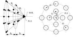
具体的,如图2所示的一种馈源排列方式,其中,图2左侧为馈源排列示意图,图2右侧为馈源的位置投影在焦平面的示意图,所述焦平面为垂直于所述孔径单元的轴线且所述焦点所在的平面;所述馈源包括:一个第一馈源和一组第二馈源;所述第二馈源的中心均匀的放置在垂直于所述孔径单元的轴线的一个圆上,且所述圆的圆心位于所述孔径单元的轴线上,所述第二馈源在焦平面上投影与焦点的距离为R(如图2左侧的示意图所示),第一馈源置于焦点处时,孔径辐射波束的半功率角为θ,且对应的增益为G dBi;相邻的两个第二馈源之间的中心距为d,第二馈源的辐射口面在同一平面上,与第一馈源的辐射口面距离为δ(δ≥0,当δ=0时,第二馈源与第一馈源的辐射口面在同一平面),第二馈源对应的孔径辐射波束的波束角记为φ,为保证波束扫描时能够实现半功率波束无缝覆盖,需满足:Specifically, a feed arrangement as shown in FIG. 2 , in which the left side of FIG. 2 is a schematic diagram of the feed arrangement, and the right side of FIG. 2 is a schematic diagram of the position of the feed projected on the focal plane, and the focal plane is vertical the axis of the aperture unit and the plane where the focal point is located; the feed source includes: a first feed source and a group of second feed sources; the center of the second feed source is evenly placed perpendicular to the On a circle of the axis of the aperture unit, and the center of the circle is located on the axis of the aperture unit, the distance between the projection of the second feed on the focal plane and the focal point is R (as shown in the schematic diagram on the left side of FIG. 2 ) shown), when the first feed is placed at the focal point, the half-power angle of the aperture radiation beam is θ, and the corresponding gain is G dBi; the center-to-center distance between two adjacent second feeds is d, and the second The radiation port surface of the feed is on the same plane, and the distance from the radiation port surface of the first feed source is δ(δ≥0, when δ=0, the radiation port surface of the second feed source and the first feed source are in the same plane ), the beam angle of the aperture radiation beam corresponding to the second feed source is denoted as φ. In order to ensure seamless coverage of the half-power beam during beam scanning, it is necessary to meet:


其中F为孔径单元的焦距,D为孔径单元的直径,k为小于等于1的常数。此时无缝扫描范围最大可以覆盖3θ的角度。而δ的取值,要使得第二馈源对应的孔径辐射波束的主瓣方向增益大于(G-3)dBi。Where F is the focal length of the aperture unit, D is the diameter of the aperture unit, and k is a constant less than or equal to 1. At this time, the seamless scanning range can cover a maximum angle of 3θ. The value of δ should be such that the gain in the main lobe direction of the aperture radiation beam corresponding to the second feed source is greater than (G-3) dBi.
具体的,如图3所示的另一种馈源排列方式,其中,图3左侧为馈源排列示意图,图3右侧为馈源的位置投影在焦平面的示意图,所述馈源包括:一个第一馈源和两组第二馈源,其中,第一组第二馈源的中心均匀的放置在一个垂直于所述孔径单元的轴线的圆上,且所述圆的圆心位于所述孔径单元的轴线上,其在焦平面上的投影与焦点的距离为R1,相邻的两个第二馈源之间的中心距为d1,第一组第二馈源对应的孔径辐射波束的波束角为φ1;第二组第二馈源的中心均匀的放置在另一个垂直于所述孔径单元的轴线的圆上,且所述圆的圆心位于所述孔径单元的轴线上,其在焦平面上的投影与焦点的距离为R2,相邻的两个第二馈源之间的中心距为d2,第二组第二馈源对应的孔径辐射波束的波束角为φ2;第一组第二馈源的辐射口面与第一馈源的辐射口面距离为δ1(δ1≥0),第二组第二馈源的辐射口面与第一馈源的辐射口面距离为δ2(δ2≥0)。第一馈源置于焦点处时,孔径辐射波束的半功率角为θ,且对应的增益为G dBi。为保证波束扫描时能够实现半功率波束无缝覆盖,需满足:Specifically, another arrangement of feeds is shown in FIG. 3 , wherein the left side of FIG. 3 is a schematic diagram of the arrangement of feeds, and the right side of FIG. 3 is a schematic diagram of the position of the feeds projected on the focal plane. The feeds include : a first feed source and two sets of second feed sources, wherein the centers of the first set of second feed sources are evenly placed on a circle perpendicular to the axis of the aperture unit, and the center of the circle is located at the On the axis of the aperture unit, the distance between its projection on the focal plane and the focal point is R1 , the center distance between two adjacent second feed sources is d1 , and the apertures corresponding to the first group of second feed sources are The beam angle of the radiation beam is φ1 ; the center of the second group of second feeds is evenly placed on another circle perpendicular to the axis of the aperture unit, and the center of the circle is located on the axis of the aperture unit , the distance between its projection on the focal plane and the focal point is R2 , the center distance between two adjacent second feed sources is d2 , and the beam angle of the aperture radiation beam corresponding to the second group of second feed sources is φ2 ; the distance between the radiation port surface of the first group of second feed sources and the radiation port surface of the first feed source is δ1 (δ1 ≥0), and the radiation port surface of the second group of second feed sources and the first feed source The radiation mouth-to-surface distance is δ2 (δ2 ≥0). When the first feed is placed at the focal point, the half-power angle of the aperture radiation beam is θ, and the corresponding gain is G dBi. To ensure seamless coverage of half-power beams during beam scanning, the following requirements must be met:


其中F为孔径单元的焦距,D为孔径单元的直径,k为小于等于1的常数。此时无缝扫描范围最大可以覆盖5θ的角度。而δ1和δ2的取值,要分别使得第一、二组第二馈源对应的孔径辐射波束的主瓣方向增益大于(G-3)dBi。Where F is the focal length of the aperture unit, D is the diameter of the aperture unit, and k is a constant less than or equal to 1. At this time, the seamless scanning range can cover an angle of 5θ at most. The values of δ1 and δ2 should be such that the gain in the main lobe direction of the aperture radiation beams corresponding to the first and second groups of the second feed sources is greater than (G-3) dBi, respectively.
进一步的,在实际应用中,可以放置n组第二馈源,此时无缝扫描范围最大可以覆盖(2n+1)θ的角度。Further, in practical applications, n groups of second feeds can be placed, and at this time, the seamless scanning range can cover an angle of (2n+1)θ at most.
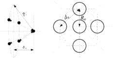
具体的,如图4所示的另一种馈源排列方式,其中,图4左侧为馈源的位置投影在焦平面的示意图,图4右侧为馈源的位置投影在与所述焦平面垂直的平面的示意图,所述馈源包括:一个第一馈源和n组第二馈源,其中第n组第二馈源的中心均匀地放置在一个垂直于所述孔径单元的轴线的圆上,且所述圆的圆心位于所述孔径单元的轴线上,其在焦平面上的投影与焦点的距离为Rn,相邻的两个第二馈源之间的中心距为dn,对应的孔径辐射波束的波束角为φn,辐射口面与第一馈源的辐射口面距离为δn(δn≥0)。为保证波束扫描时能够实现半功率波束无缝覆盖,需满足:Specifically, another arrangement of feeds is shown in FIG. 4 , wherein the left side of FIG. 4 is a schematic diagram of the position of the feed being projected on the focal plane, and the right side of FIG. 4 is the projection of the position of the feed on the focal plane. A schematic diagram of a plane perpendicular to the plane, the feed source includes: a first feed source and n groups of second feed sources, wherein the centers of the nth group of second feed sources are evenly placed on a vertical axis of the aperture unit. on the circle, and the center of the circle is located on the axis of the aperture unit, the distance between its projection on the focal plane and the focal point is Rn , and the center distance between two adjacent second feed sources is dn , the beam angle of the corresponding aperture radiation beam is φn , and the distance between the radiation port surface and the radiation port surface of the first feed source is δn (δn ≥0). To ensure seamless coverage of half-power beams during beam scanning, the following requirements must be met:


而δn的取值,要使得第n组第二馈源对应的孔径辐射波束的主瓣方向增益大于(G-3)dBi。The value of δn should be such that the gain in the main lobe direction of the aperture radiation beam corresponding to the nth group of second feed sources is greater than (G-3) dBi.
在实际应用中,馈源作为高增益天线的初级辐射器,并经孔径单元反射或折射实现电磁波的聚焦,实现天线的高增益。在具体实施方式中,若孔径单元为反射面,则可以仅用一个主反射面,此时,第一馈源应位于主反射面的焦点处,所述至少两个馈源的排列应符合上述排列方式以实现无缝扫描;也可以使用一个副反射面和一个主反射面的方式,此时考虑所述至少两个馈源在副反射面的对称面上形成多个虚拟焦点,所述多个虚拟焦点的排列应符合上述排列方式以实现无缝扫描。若孔径单元为透镜,此时,第一馈源应位于透镜的焦点处,所述至少两个馈源的排列应符合上述排列方式以实现无缝扫描。In practical applications, the feed is used as the primary radiator of a high-gain antenna, and is reflected or refracted by the aperture unit to realize the focusing of electromagnetic waves and achieve high antenna gain. In a specific implementation manner, if the aperture unit is a reflective surface, only one main reflective surface can be used. In this case, the first feed should be located at the focal point of the main reflective surface, and the arrangement of the at least two feeds should conform to the above In this case, it is considered that the at least two feeds form multiple virtual focal points on the symmetry plane of the sub-reflection surface, and the multiple The arrangement of the virtual focal points should conform to the above arrangement for seamless scanning. If the aperture unit is a lens, in this case, the first feed should be located at the focal point of the lens, and the arrangement of the at least two feeds should conform to the above arrangement to achieve seamless scanning.
示例性的,所述至少两个馈源还可以放置在所述孔径单元的焦点周围,所述至少两个馈源中的任一馈源发送的波束通过所述孔径单元反射或折射后,与所述孔径单元的轴线形成一个夹角。具体的,该夹角的值与每个馈源与焦点的偏移距离和方位角有关;由于每个馈源都放置在焦点周围的不同位置,因此,每个馈源的反射波束方向也会不一致,从而形成一个较大的波束覆盖范围。Exemplarily, the at least two feeds may also be placed around the focal point of the aperture unit, and after the beam sent by any one of the at least two feeds is reflected or refracted by the aperture unit, The axes of the aperture units form an included angle. Specifically, the value of the included angle is related to the offset distance and azimuth angle between each feed and the focal point; since each feed is placed at a different position around the focal point, the reflected beam direction of each feed will also inconsistent, resulting in a larger beam coverage.
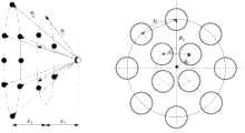
如图5所示的另一种馈源排列方式,所述多馈源天线101包括至少两个馈源;所述至少两个馈源的中心均匀的放置在一个垂直于所述孔径单元的轴线的圆上,且所述圆的圆心位于所述孔径单元的轴线上。其中,图5左侧为馈源排列的示意图,图5右侧为馈源的位置投影在焦平面的示意图,所述焦平面为垂直于所述孔径单元的轴线且所述焦点所在的平面,馈源在焦平面上投影与焦点的距离为R。相邻的两个馈源之间的中心距为d,所述馈源的辐射口面与所述焦点距离为δ(δ≥0,当δ=0时,所述馈源的辐射口面在焦平面上),馈源对应的孔径辐射波束的波束角记为φ。假设将馈源置于焦点处时,孔径辐射波束的半功率角为θ,且对应的增益为G dBi;为保证波束扫描时能够实现半功率波束无缝覆盖,需满足:As shown in FIG. 5 in another feed arrangement, the


其中F为孔径单元的焦距,D为孔径单元的直径,k为小于等于1的常数。此时无缝扫描范围最大可以覆盖2θ的角度。而δ的取值,要使得馈源对应的孔径辐射波束的主瓣方向增益大于(G-3)dBi。Where F is the focal length of the aperture unit, D is the diameter of the aperture unit, and k is a constant less than or equal to 1. At this time, the seamless scanning range can cover the angle of 2θ at most. The value of δ should make the gain in the main lobe direction of the aperture radiation beam corresponding to the feed source greater than (G-3) dBi.
具体的,如图6所示的另一种馈源排列方式,其中,图6左侧为馈源的位置投影在焦平面的示意图,图6右侧为馈源的位置投影在与所述焦平面垂直的平面的示意图,所述馈源包括:两组馈源,其中,第一组馈源的中心均匀的放置在一个垂直于所述孔径单元的轴线的圆上,且所述圆的圆心位于所述孔径单元的轴线上,其在焦平面上的投影与焦点的距离为R1,相邻的两个馈源之间的中心距为d1,第一组馈源的孔径辐射波束的波束角为φ1;第二组馈源的中心均匀的放置在一个垂直于所述孔径单元的轴线的圆上,且所述圆的圆心位于所述孔径单元的轴线上,其在焦平面上的投影与焦点的距离为R2,相邻的两个馈源之间的中心距为d2,第二组馈源的孔径辐射波束的波束角为φ2;第一组馈源的辐射口面与所述焦点距离为δ1(δ1≥0),第二组馈源的辐射口面与所述焦点距离为δ2(δ2≥0)。假设将馈源置于焦点处时,孔径辐射波束的半功率角为θ,且对应的增益为G dBi;为保证波束扫描时能够实现半功率波束无缝覆盖,需满足:Specifically, another arrangement of feeds is shown in FIG. 6 , wherein the left side of FIG. 6 is a schematic diagram of the position of the feed being projected on the focal plane, and the right side of FIG. 6 is the projection of the position of the feed on the focal plane. A schematic diagram of a plane perpendicular to the plane, the feed source includes: two groups of feed sources, wherein the center of the first group of feed sources is evenly placed on a circle perpendicular to the axis of the aperture unit, and the center of the circle is Located on the axis of the aperture unit, the distance between its projection on the focal plane and the focal point is R1 , the center distance between two adjacent feeds is d1 , the aperture radiation beam of the first group of feeds is The beam angle is φ1 ; the center of the second group of feeds is evenly placed on a circle perpendicular to the axis of the aperture unit, and the center of the circle is located on the axis of the aperture unit, which is on the focal plane The distance between the projection and the focal point is R2 , the center distance between two adjacent feeds is d2 , the beam angle of the aperture radiation beam of the second group of feeds is φ2 ; the radiation port of the first group of feeds The distance between the surface and the focal point is δ1 (δ1 ≥0), and the distance between the radiation port surface of the second group of feeds and the focal point is δ2 (δ2 ≥0). It is assumed that when the feed is placed at the focal point, the half-power angle of the aperture radiation beam is θ, and the corresponding gain is G dBi; in order to ensure seamless coverage of the half-power beam during beam scanning, it is necessary to satisfy:


其中F为孔径单元的焦距,D为孔径单元的直径,k为小于等于1的常数。此时无缝扫描范围最大可以覆盖4θ的角度。而δ1和δ2的取值,要分别使得第一和二组馈源对应的孔径辐射波束的主瓣方向增益大于(G-3)dBi。Where F is the focal length of the aperture unit, D is the diameter of the aperture unit, and k is a constant less than or equal to 1. At this time, the seamless scanning range can cover the maximum angle of 4θ. The values of δ1 and δ2 should be such that the gain in the main lobe direction of the aperture radiation beams corresponding to the first and second groups of feed sources is greater than (G-3) dBi, respectively.
进一步的,在实际应用中,可以放置n组馈源,此时无缝扫描范围最大可以覆盖2n*θ的角度。Further, in practical applications, n groups of feeds can be placed, and the seamless scanning range can cover an angle of 2n*θ at most.
具体的,如图7所示的另一种馈源排列方式,其中,图7左侧为馈源的位置投影在焦平面的示意图,图7右侧为馈源的位置投影在与所述焦平面垂直的平面的示意图,所述馈源包括:n组馈源,其中第n组馈源的中心均匀地放置在一个垂直于所述孔径单元的轴线的圆上,且所述圆的圆心位于所述孔径单元的轴线上,其在焦平面上的投影与焦点的距离为Rn,相邻的两个馈源之间的中心距为dn,对应的孔径辐射波束的波束角为φn,所述馈源的辐射口面与所述焦点距离为δn(δn≥0)。假设将馈源置于焦点处时,孔径辐射波束的半功率角为θ,且对应的增益为G dBi;为保证波束扫描时能够实现半功率波束无缝覆盖,需满足:Specifically, another arrangement of feeds is shown in FIG. 7 , in which the left side of FIG. 7 is a schematic diagram of the position of the feed being projected on the focal plane, and the right side of FIG. 7 is the projection of the position of the feed on the focal plane. A schematic diagram of a plane perpendicular to the plane, the feed includes: n groups of feeds, wherein the center of the nth group of feeds is evenly placed on a circle perpendicular to the axis of the aperture unit, and the center of the circle is located at On the axis of the aperture unit, the distance between its projection on the focal plane and the focal point is Rn , the center distance between two adjacent feeds is dn , and the beam angle of the corresponding aperture radiation beam is φn , the distance between the radiation aperture of the feed and the focal point is δn (δn ≥ 0). It is assumed that when the feed is placed at the focal point, the half-power angle of the aperture radiation beam is θ, and the corresponding gain is G dBi; in order to ensure seamless coverage of the half-power beam during beam scanning, it is necessary to satisfy:


而δn的取值,要使得第n组馈源对应的孔径辐射波束的主瓣方向增益大于(G-3)dBi。The value of δn should make the gain in the main lobe direction of the aperture radiation beam corresponding to the nth group of feeds greater than (G-3) dBi.
可以理解的是,上述对馈源的位置描述仅是示例性的,在实际应用中,馈源的位置还可能有其它的放置方式,此处具体不作限定。It can be understood that the above description of the position of the feed source is only exemplary, and in practical applications, the position of the feed source may also have other placement manners, which are not specifically limited here.
可以理解的是,上述对馈源的描述仅是示例性的,假定了同一组馈源的辐射增益是相同的,在实际应用中,由于馈源之间的个体差异,又或者基于特殊设计的考虑,同一组馈源的辐射增益不会完全相同,可以取其中最小的辐射波束角作为计算基准。It can be understood that the above description of the feeds is only exemplary, and it is assumed that the radiation gains of the same group of feeds are the same. In practical applications, due to individual differences between feeds, or based on special design Considering that the radiation gains of the same group of feeds are not exactly the same, the smallest radiation beam angle can be taken as the calculation reference.
所述馈源切换模块102包括多路开关,每个所述馈源分别与馈源切换模块102中的一路开关相连接。The
示例性的,所述馈源切换模块中可以为射频开关,或巴特勒(Butler)矩阵开关;其中,所述射频开关每次只能选择一路馈源;而所述Butler矩阵开关则可以一次选择一路或多路馈源。在实际应用中,若使用Butler矩阵开关一次选择多路馈源,则可以同时使用所述多路馈源进行信号的发送和接收。Exemplarily, the feed switching module may be a radio frequency switch or a Butler matrix switch; wherein, the radio frequency switch can only select one feed at a time; and the Butler matrix switch can be selected at one time. One or more feeds. In practical applications, if a Butler matrix switch is used to select multiple feeds at one time, the multiple feeds can be used to transmit and receive signals at the same time.
所述切换控制模块103,用于通过所述馈源切换模块102,使能每个所述馈源进行信号质量检测,并选择信号质量最好的一个所述馈源作为工作馈源,即馈源切换模块102将在后续的一段时间内一直导通信号质量最好的馈源的一路开关。可以理解的是,所述工作馈源指的是在某个时间段上波束扫描天线中进行实际工作的馈源,并不是将一个馈源永远固定作为收发固定工作的馈源。The switching
在实际应用中,为了确保能够选择到最优的馈源配置,切换控制模块103中设置的控制逻辑需要保证在馈源选择过程中所有的馈源或馈源组合都能够被遍历到。In practical applications, in order to ensure that the optimal feed configuration can be selected, the control logic set in the switching
具体的,所述切换控制模块103可以进一步包括波束对准模块1031,用于通过对所述馈源切换模块进行切换控制,并选择信号质量最好的一个所述馈源作为工作馈源。在实际应用中,所述波束对准模块1031为一种控制模块,其中可以设置对馈源切换模块的控制逻辑,以及选择馈源的逻辑;示例性的,波束对准模块1031可以为一种数字信号处理(DSP,digital signal processor)或中央处理器(CPU,Central Processing Unit)模块。Specifically, the switching
示例性的,当通过馈源切换模块102选择其中一个馈源为工作馈源时,接收另一微波系统发送的信号,然后对该接收信号进行信号质量检测。具体的,所述信号质量包括:接收信号强度,接收信号的信噪比(SNR,Signal to Noise Ratio),或接收信号的均方误差(MSE,Mean Square Error)中任意一项或两项以上的组合。若检测的是接收信号强度,如接收电平或接收功率,则通过检测接收链路某个点上的信号来获得。若检测的是SNR或MSE,则可以通过基带的解调模块获得。Exemplarily, when one of the feeds is selected as the working feed by the
在本发明实施例中,放置了多个馈源,并且,每个所述馈源分别与馈源切换模块中的一路开关相连接;切换控制模块可以通过所述馈源切换模块,遍历每个所述馈源进行信号质量检测,并选择信号质量最好的一个所述馈源作为工作馈源,从而避免了人工转动天线进行调试和对准。In the embodiment of the present invention, a plurality of feed sources are placed, and each of the feed sources is respectively connected to a switch in the feed source switching module; the switching control module can traverse each feed source switching module through the feed source switching module. The feeds are subjected to signal quality detection, and one of the feeds with the best signal quality is selected as the working feed, thereby avoiding the need to manually rotate the antenna for debugging and alignment.
在实际应用中,微波系统的中天线会放置在室外,因此,在某些强风的天气下,天线会发生晃动,以致于容易造成链路中断;本发明实施例提供了相应的解决方案,请参阅图8,本发明实施例中波束扫描天线的另一个实施例包括:In practical applications, the mid-antenna of the microwave system will be placed outdoors. Therefore, in some strong winds, the antenna will shake, which may easily cause the link to be interrupted. The embodiment of the present invention provides a corresponding solution, please Referring to FIG. 8, another embodiment of the beam scanning antenna in the embodiment of the present invention includes:
多馈源天线101,馈源切换模块102,切换控制模块103,
其中,多馈源天线101,馈源切换模块102和切换控制模块103之间的连接关系可以参阅上述图1实施例,此处不作赘述。The connection relationship among the
进一步的,所述切换控制模块103还可以包括:波束对准模块1031以及波束跟踪模块1032;Further, the
其中,所述波束对准模块1031用于通过预置的控制逻辑对所述馈源切换模块进行切换控制,并根据选择信号质量最好的一个所述馈源作为工作馈源。Wherein, the
所述波束跟踪模块1032用于检测信号质量最好的馈源是否发生改变,若是,通知所述波束对准模块1031选择信号质量最好的一个所述馈源作为工作馈源。The
具体的,所述波束跟踪模块1032指示所述馈源切换模块102对所述多个馈源进行遍历,并在遍历过程中对每个馈源使能时进行信号质量检测,根据信号质量检测的结果确定信号质量最好的馈源是否发生改变。Specifically, the
具体的,所述遍历指的是逐个对所述馈源进行使能,当一个馈源完成信号质量检测之后,切换至另一个馈源进行信号质量检测。Specifically, the traversal refers to enabling the feeds one by one, and after one feed completes signal quality detection, switches to another feed for signal quality detection.
具体的,由于馈源切换需要一定时间,因此,馈源与馈源之间切换的过程需要在业务数据处理的间隙时间段内进行,或者,在馈源与馈源之间切换时对业务数据进行缓存,以避免影响业务数据的传输。Specifically, since it takes a certain amount of time to switch between feeds, the process of switching between feeds needs to be performed within the gap period of service data processing. Cache to avoid affecting the transmission of business data.
具体的,为避免两端的波束扫描天线同时扫描无法锁定,当本端波束扫描天线的波束跟踪模块1032启动馈源遍历时,可以向对端波束扫描天线发送第一通知消息,通告对端“本端当前处于扫描状态”,当对端接收到该第一通知消息时,对端的波束跟踪模块则锁定扫描,即保持工作馈源不变。当本端波束跟踪模块1032结束馈源遍历时,也可以通知对端“当前不处于扫描状态”,当对端接收到该信息时,对端波束跟踪模块则解除扫描锁定,即可根据情况启动跟踪馈源遍历。结束馈源遍历的通知机制可以是本端发送第二通知消息给对端,也可以是本端停止发送第一通知消息,对端在预设时间内没有收到第一通知消息即认为“当前不处于扫描状态”。Specifically, in order to prevent the beam scanning antennas at both ends from scanning at the same time and unable to lock, when the
可选的,在实际应用中,可以在波束跟踪模块1032设置一个固定周期,每隔预置时长指示所述馈源切换模块对所述馈源进行遍历,使得每个被使能的所述馈源分别进行信号质量检测,根据信号质量检测的结果确定信号质量最好的馈源是否发生改变。Optionally, in practical applications, a fixed period can be set in the
进一步的,也可以根据接收信号质量劣化来确定是否需要进行信号质量的检测,波束跟踪模块1032实时监测接收信号质量,当检测到当前工作馈源的接收信号质量低于某一预设的阈值时,对所述馈源进行遍历,使得每个被使能的所述馈源分别进行信号质量检测,根据信号质量检测的结果确定信号质量最好的馈源是否发生改变。Further, it is also possible to determine whether the signal quality needs to be detected according to the deterioration of the received signal quality. The
进一步的,还可以由用户发起信号质量的检测的流程,用户可以向波束跟踪模块1032发送用户指令,指示所述馈源切换模块对所述馈源进行遍历,使得每个被使能的所述馈源分别进行信号质量检测,根据信号质量检测的结果确定信号质量最好的馈源是否发生改变。Further, the user can also initiate the signal quality detection process, and the user can send a user instruction to the
本发明实施例还提供了一种包括有上述波束扫描天线的微波系统,请参阅图9,本发明实施例中微波系统的一个实施例包括:An embodiment of the present invention further provides a microwave system including the above-mentioned beam scanning antenna. Referring to FIG. 9, an embodiment of the microwave system in the embodiment of the present invention includes:
基带处理模块20,中射频收发模块30和波束扫描天线10;a
所述基带处理模块20与所述中射频收发模块30连接,所述基带处理模块20用于对发送和接收的信号分别进行调制和解调,并根据所述发送和接收的信号实现业务处理。The
所述中射频收发模块30用于实现接收与发送的信号分离;具体的,所述中射频收发模块30包括:发送链路Tx、接收链路Rx。The mid-radio
所述波束扫描天线10与所述中射频收发模块40相连,所述波束扫描天线包括:多馈源天线101,馈源切换模块102,切换控制模块103;The
所述多馈源天线101包括至少两个馈源、和一个孔径单元;其中,所述孔径单元用于通过反射或折射的方式将电磁波信号聚焦。所述孔径单元可以为反射面或透镜。The
所述馈源切换模块102包括多路开关,每个所述馈源分别与馈源切换模块102中的一路开关相连接。The
所述切换控制模块103用于通过所述馈源切换模块102,使能每个所述馈源进行信号质量检测,并选择信号质量最好的一个所述馈源作为工作馈源。即馈源切换模块102将在后续的一段时间内一直导通信号质量最好的馈源的一路开关。The switching
可以理解的是,所述工作馈源指的是在某个时间段上波束扫描天线中进行实际工作的馈源,并不是将一个馈源永远固定作为收发固定工作的馈源。It can be understood that, the working feed refers to a feed that actually works in the beam scanning antenna in a certain period of time, rather than a feed that is permanently fixed as a feed that transmits and receives fixed work.
在实际应用中,为了确保能够选上最优的馈源,切换控制模块103中设置的控制逻辑需要保证所有的馈源都至少被使能一遍。In practical applications, in order to ensure that an optimal feed source can be selected, the control logic set in the switching
下面对波束对准方法进行描述,请参阅图10,本发明实施例中波束对准方法的一个实施例包括:The beam alignment method is described below, with reference to FIG. 10, an embodiment of the beam alignment method in the embodiment of the present invention includes:
1001、切换控制模块指示馈源切换模块使能多馈源天线中的每个馈源;1001. The switching control module instructs the feed switching module to enable each feed in the multi-feed antenna;
切换控制模块指示馈源切换模块使能多馈源天线中的每个馈源,使得所述馈源分别进行信号质量检测;所述多馈源天线包括孔径单元,以及至少两个馈源,所述馈源用于辐射电磁波信号,所述孔径单元用于通过反射或折射的方式将电磁波信号聚焦。示例性的,所述孔径单元可以为反射面或透镜。The switching control module instructs the feed switching module to enable each feed in the multi-feed antenna, so that the feeds perform signal quality detection respectively; the multi-feed antenna includes an aperture unit and at least two feeds, so The feed source is used for radiating electromagnetic wave signals, and the aperture unit is used for focusing the electromagnetic wave signals by means of reflection or refraction. Exemplarily, the aperture unit may be a reflective surface or a lens.
所述馈源切换模块包括包括多路开关,每个所述馈源分别与馈源切换模块中的一路开关相连接。The feed switching module includes multiple switches, and each of the feeds is respectively connected to a switch in the feed switching module.
在本发明实施例中,馈源之间的位置关系请参阅上述装置实施例此处不再赘述。In this embodiment of the present invention, for the positional relationship between the feeds, please refer to the above-mentioned apparatus embodiment and will not be repeated here.
示例性的,所述馈源切换模块可以为射频开关,或巴特勒(Butler)矩阵开关;其中,所述射频开关每次只能选择一路馈源;而所述Butler矩阵开关则可以一次选择一路或多路馈源。在实际应用中,若使用Butler矩阵开关一次选择多路馈源,则可以同时使用所述多路馈源进行信号的发送和接收。Exemplarily, the feed switching module may be a radio frequency switch or a Butler matrix switch; wherein, the radio frequency switch can only select one feed at a time; and the Butler matrix switch can select one feed at a time. or multiple feeds. In practical applications, if a Butler matrix switch is used to select multiple feeds at one time, the multiple feeds can be used to transmit and receive signals at the same time.
1002、切换控制模块获取所述每个馈源进行信号质量检测的结果;1002. The switching control module obtains a result of performing signal quality detection on each of the feeds;
示例性的,当一路馈源的开关被导通时,接收另一端的波束扫描天线发送的信号,然后对该信号进行信号质量检测。在完成信号质量检测后所述馈源会将信号质量检测的结果发送给所述切换控制模块。Exemplarily, when the switch of one feed source is turned on, the signal sent by the beam scanning antenna at the other end is received, and then the signal quality is detected for the signal. After completing the signal quality detection, the feed will send the result of the signal quality detection to the handover control module.
具体的,所述信号质量包括:接收信号强度,接收信号的信噪比(SNR,Signal toNoise Ratio),或接收信号的均方误差(MSE,Mean Square Error)中任意一项或两项以上的组合。若检测的是接收信号强度,如接收电平或接收功率,则通过检测接收链路某个点上的信号来获得。若检测的是SNR或MSE,则可以通过基带的解调模块获得。Specifically, the signal quality includes: received signal strength, signal to noise ratio (SNR, Signal to Noise Ratio) of the received signal, or mean square error (MSE, Mean Square Error) of the received signal. Any one or more than two combination. If the received signal strength is detected, such as received level or received power, it is obtained by detecting the signal at a certain point of the receiving link. If the detected SNR or MSE, it can be obtained through the demodulation module of the baseband.
1003、切换控制模块根据所述信号质量检测的结果选择信号质量最好的一个所述馈源作为工作馈源。1003. The switching control module selects one of the feeds with the best signal quality as a working feed according to the result of the signal quality detection.
可以理解的是,所述工作馈源指的是在某个时间段上波束扫描天线中进行实际工作的馈源,并不是将一个馈源永远固定作为固定工作的馈源。It can be understood that, the working feed refers to a feed that actually works in the beam scanning antenna in a certain period of time, rather than a feed that is permanently fixed as a fixed working feed.
在实际应用中,为了确保能够选择到选上最优的馈源配置,切换控制模块中设置的控制逻辑需要保证在馈源选择过程中所有的馈源或馈源组合都能够至少被遍历到使能一遍。In practical applications, in order to ensure that the optimal feed configuration can be selected, the control logic set in the switching control module needs to ensure that all feeds or feed combinations can be traversed at least until the Can once.
可选的,确定信号质量最好的馈源时,可以仅根据信号的功率强度,信号的SNR或信号的MSE任意一项参数来确定,即选择功率强度最高的,或选择SNR最高的,或MSE最小的;也可以综合信号的功率强度,信号的SNR以及信号的MSE任意两个以上的条件,并结合相应的权重,选择最信号质量最好的馈源。具体的实现方式可以根据实际需求而定,此处不作限定。Optionally, when determining the feed with the best signal quality, it can be determined only according to the power strength of the signal, the SNR of the signal or the MSE of the signal, that is, select the one with the highest power strength, or select the one with the highest SNR, or MSE is the smallest; it is also possible to combine any two or more conditions of signal power strength, signal SNR and signal MSE, and combine the corresponding weights to select the feed with the best signal quality. The specific implementation manner may be determined according to actual requirements, which is not limited here.
在本发明实施例中,放置了多个馈源,并且,每个所述馈源分别与馈源切换模块中的一路开关相连接;切换控制模块可以通过所述馈源切换模块,使能每个所述馈源进行信号质量检测,并选择信号质量最好的一个所述馈源作为工作馈源,从而避免了对天线进行人工调试和对准。In the embodiment of the present invention, multiple feed sources are placed, and each of the feed sources is respectively connected to a switch in the feed source switching module; the switching control module can enable each feed source switching module through the feed source switching module. Perform signal quality detection on each of the feeds, and select the feed with the best signal quality as the working feed, thereby avoiding manual debugging and alignment of the antenna.
进一步的,在实际应用中,由于微波系统的中天线会放置在室外,因此,在某些强风的天气下,天线会发生晃动,以致于容易造成链路中断;本发明实施例提供了相应的解决方案,请参阅图11,本发明实施例中波束扫描天线的另一个实施例包括:Further, in practical applications, since the mid-antenna of the microwave system will be placed outdoors, the antenna will sway in some strong wind weather, which may easily cause the link to be interrupted; the embodiments of the present invention provide corresponding For the solution, please refer to FIG. 11. Another embodiment of the beam scanning antenna in the embodiment of the present invention includes:
1101、切换控制模块指示所述馈源切换模块对所述馈源进行遍历;1101. The switching control module instructs the feed switching module to traverse the feed;
切换控制模块指示所述馈源切换模块对所述馈源进行遍历,使得每个被使能的所述馈源分别进行信号质量检测;The switching control module instructs the feed switching module to traverse the feed, so that each enabled feed performs signal quality detection respectively;
在本发明实施例中,馈源之间的位置关系请参阅上述装置实施例此处不再赘述。In this embodiment of the present invention, for the positional relationship between the feeds, please refer to the above-mentioned apparatus embodiment and will not be repeated here.
具体的,切换控制模块还可以包括:波束对准模块以及波束跟踪模块;其中,所述波束对准模块用于通过预置的控制逻辑对所述馈源切换模块进行切换控制,并根据选择信号质量最好的一个所述馈源作为工作馈源。所述波束跟踪模块用于检测信号质量最好的馈源是否发生改变,若是,通知所述波束对准模块选择信号质量最好的一个所述馈源作为工作馈源。具体的,由于馈源切换需要一定时间,因此,馈源与馈源之间切换的过程需要在业务数据处理的间隙时间段内进行,或者,在馈源与馈源之间切换时对业务数据进行缓存,以避免影响业务数据的传输。Specifically, the switching control module may further include: a beam alignment module and a beam tracking module; wherein, the beam alignment module is configured to perform switching control on the feed switching module through preset control logic, and according to the selection signal The best quality one of the feeds is used as the working feed. The beam tracking module is used to detect whether the feed with the best signal quality has changed, and if so, notify the beam alignment module to select the feed with the best signal quality as the working feed. Specifically, since it takes a certain amount of time to switch between feeds, the process of switching between feeds needs to be performed within the gap period of service data processing. Cache to avoid affecting the transmission of business data.
具体的,为避免两端的波束扫描天线同时扫描无法锁定,当本端波束扫描天线的波束跟踪模块启动馈源遍历时,可以向对端波束扫描天线发送第一通知消息,通告对端“当前处于扫描状态”,当对端接收到该第一通知消息时,对端的波束跟踪模块则锁定扫描,即保持工作馈源不变。当本端波束跟踪模块结束馈源遍历时,也可以通知对端“本端当前不处于扫描状态”,当对端接收到该信息时,对端波束跟踪模块则解除扫描锁定,即可根据情况启动跟踪馈源遍历。结束馈源遍历的通知机制可以是本端发送第二通知消息给对端,也可以是本端停止发送第一通知消息,对端在预设时间内没有收到第一通知消息即认为“当前不处于扫描状态”。Specifically, in order to prevent the beam scanning antennas at both ends from scanning at the same time and unable to lock, when the beam tracking module of the beam scanning antenna at the local end starts the feed traversal, it can send a first notification message to the beam scanning antenna at the opposite end, notifying the opposite end that "currently in the Scanning state", when the opposite end receives the first notification message, the beam tracking module of the opposite end locks the scanning, that is, keeps the working feed unchanged. When the local beam tracking module ends the feed traversal, it can also notify the opposite end that "the local end is not currently in the scanning state". When the opposite end receives this information, the opposite end beam tracking module will release the scanning lock, which can be determined according to the situation. Start a tracking feed traversal. The notification mechanism for ending the feed traversal can be that the local end sends the second notification message to the opposite end, or the local end stops sending the first notification message, and the opposite end does not receive the first notification message within the preset time. Not scanning".
可选的,在实际应用中,触发切换控制模块再次进行对各个馈源进行信号质量检测的方式有多种,包括:Optionally, in practical applications, there are various ways to trigger the switching control module to perform signal quality detection on each feed again, including:
一、定期发起;1. Periodic initiation;
用户可以设置一个固定时长,并设定所述波束跟踪模块每隔预置时长指示所述馈源切换模块对所述馈源进行遍历。The user can set a fixed duration, and set the beam tracking module to instruct the feed switching module to traverse the feed every preset duration.
二、根据指令发起;2. Initiate according to the instruction;
由用户发起信号检测的流程,用户可以向波束跟踪模块发送用户指令,指示所述馈源切换模块对所述馈源进行遍历。具体的,所述用户指令可以通过遥控、设定程序或预设按钮发送,具体的实现形式可以根据实际需求而定,此处不作限定。The process of signal detection is initiated by the user, and the user can send a user instruction to the beam tracking module, instructing the feed switching module to traverse the feed. Specifically, the user instruction can be sent through a remote control, a setting program or a preset button, and the specific implementation form can be determined according to actual needs, which is not limited here.
三、根据接收信号质量发起;3. Initiate according to the received signal quality;
波束跟踪模块实时监测接收信号质量,当检测到当前工作馈源的接收信号质量低于某一预设的阈值时对所述馈源进行遍历,使得每个被使能的所述馈源分别进行信号质量检测。The beam tracking module monitors the quality of the received signal in real time, and traverses the feed when it is detected that the quality of the received signal of the current working feed is lower than a preset threshold, so that each enabled feed is performed separately. Signal quality detection.
1102、切换控制模块获取所述每个馈源进行信号质量检测的结果;1102. The switching control module obtains a result of performing signal quality detection on each of the feeds;
示例性的,当一路馈源的开关被导通时,接收另一端的波束扫描天线发送的信号,然后对该信号进行信号质量检测。在完成信号质量检测后所述馈源会将信号质量检测的结果发送给所述切换控制模块。Exemplarily, when the switch of one feed source is turned on, the signal sent by the beam scanning antenna at the other end is received, and then the signal quality is detected for the signal. After completing the signal quality detection, the feed will send the result of the signal quality detection to the handover control module.
1103、切换控制模块选择信号质量最好的一个所述馈源作为工作馈源。1103. The switching control module selects one of the feeds with the best signal quality as the working feed.
在一个遍历周期内,切换控制模块选择信号质量最好的一个所述馈源作为工作馈源。可以理解的是,所述工作馈源指的是在某个时间段上波束扫描天线中进行实际工作的馈源,并不是将一个馈源永远固定作为收发固定工作的馈源。In one traversal period, the switching control module selects one of the feeds with the best signal quality as the working feed. It can be understood that, the working feed refers to a feed that actually works in the beam scanning antenna in a certain period of time, rather than a feed that is permanently fixed as a feed that transmits and receives fixed work.
具体的,各个馈源依次都使能一遍的时间段为一个遍历周期。Specifically, a time period in which each feed is enabled in sequence once is a traversal cycle.
在本发明实施例中,工作馈源根据实际情况进行调整,即使微波系统中的天线因晃动使得馈源发生了偏移,切换控制模块依然可以自动重新选择一个信号质量最好的馈源作为工作馈源,使得微波链路的信号收发质量不会受到太大的影响。In the embodiment of the present invention, the working feed is adjusted according to the actual situation. Even if the antenna in the microwave system is shifted due to shaking, the switching control module can still automatically re-select a feed with the best signal quality as the working feed. feed, so that the signal transmission and reception quality of the microwave link will not be greatly affected.
以上所述,仅为本发明的具体实施方式,但本发明的保护范围并不局限于此,任何熟悉本技术领域的技术人员在本发明揭露的技术范围内,可轻易想到变化或替换,都应涵盖在本发明的保护范围之内。因此,本发明的保护范围应所述以权利要求的保护范围为准。The above are only specific embodiments of the present invention, but the protection scope of the present invention is not limited thereto. Any person skilled in the art can easily think of changes or substitutions within the technical scope disclosed by the present invention. should be included within the protection scope of the present invention. Therefore, the protection scope of the present invention should be based on the protection scope of the claims.
Claims (31)


Applications Claiming Priority (1)
| Application Number | Priority Date | Filing Date | Title |
|---|---|---|---|
| PCT/CN2014/084383WO2016023206A1 (en) | 2014-08-14 | 2014-08-14 | Beam scanning antenna, microwave system and beam alignment method |
Publications (2)
| Publication Number | Publication Date |
|---|---|
| CN106663877A CN106663877A (en) | 2017-05-10 |
| CN106663877Btrue CN106663877B (en) | 2020-06-26 |
Family
ID=55303806
Family Applications (1)
| Application Number | Title | Priority Date | Filing Date |
|---|---|---|---|
| CN201480080892.9AActiveCN106663877B (en) | 2014-08-14 | 2014-08-14 | A beam scanning antenna, microwave system and beam alignment method |
Country Status (4)
| Country | Link |
|---|---|
| US (1) | US10290947B2 (en) |
| EP (1) | EP3171456B1 (en) |
| CN (1) | CN106663877B (en) |
| WO (1) | WO2016023206A1 (en) |
Families Citing this family (13)
| Publication number | Priority date | Publication date | Assignee | Title |
|---|---|---|---|---|
| CN106207497B (en)* | 2016-08-30 | 2024-01-05 | 广东通宇通讯股份有限公司 | Multi-beam antenna system and method for constructing beams thereof |
| WO2018102971A1 (en)* | 2016-12-05 | 2018-06-14 | 华为技术有限公司 | Beam tracking apparatus and method, and antenna system |
| CN109479016A (en)* | 2016-12-06 | 2019-03-15 | 华为技术有限公司 | Beam selection system, relay method and device |
| TWI686998B (en)* | 2017-01-23 | 2020-03-01 | 啓碁科技股份有限公司 | Antenna system |
| CN108736171A (en)* | 2018-05-18 | 2018-11-02 | 成都泰格微波技术股份有限公司 | A kind of wide-angle scanning multibeam lens antenna |
| CN110875763A (en)* | 2018-08-31 | 2020-03-10 | 华为技术有限公司 | Communication feed point determining method and communication equipment |
| CN113169446B (en)* | 2018-12-20 | 2023-09-01 | 华为技术有限公司 | Multiple-input multiple-output antenna, base station and communication system |
| CN111585004B (en)* | 2019-02-19 | 2022-05-03 | 正文科技股份有限公司 | Antenna device, communication device and steering adjustment method thereof |
| CN110739549B (en)* | 2019-10-29 | 2021-05-11 | Oppo广东移动通信有限公司 | Array Lenses, Lens Antennas and Electronic Devices |
| CN112034266B (en)* | 2020-05-25 | 2023-06-23 | 北京中测国宇科技有限公司 | Millimeter wave multi-feed compact range testing system |
| CN114498080A (en)* | 2020-11-11 | 2022-05-13 | 中国移动通信有限公司研究院 | A lens multi-beam antenna |
| CN113543017B (en)* | 2021-06-02 | 2022-07-29 | 北京邮电大学 | Beam switching method and related equipment for mmWave Internet of Vehicles |
| CN117517847B (en)* | 2024-01-04 | 2024-04-09 | 南京纳特通信电子有限公司 | Miniaturized movable K-band broadband radiation testing system and method |
Citations (6)
| Publication number | Priority date | Publication date | Assignee | Title |
|---|---|---|---|---|
| US5736963A (en)* | 1995-03-20 | 1998-04-07 | Agence Spatiale Europeenne | Feed device for a multisource and multibeam antenna |
| US7193562B2 (en)* | 2004-11-22 | 2007-03-20 | Ruckus Wireless, Inc. | Circuit board having a peripheral antenna apparatus with selectable antenna elements |
| CN101331648A (en)* | 2006-04-14 | 2008-12-24 | 松下电器产业株式会社 | Polarization switching-variable directivity antenna |
| WO2012161612A1 (en)* | 2011-05-23 | 2012-11-29 | Autonomous Non-Commercial Organization "Research Institute "Sitronics Labs"" | Electronically beam steerable antenna device |
| WO2013058673A1 (en)* | 2011-10-20 | 2013-04-25 | Limited Liability Company "Radio Gigabit" | System and method of relay communication with electronic beam adjustment |
| CN103579757A (en)* | 2012-07-24 | 2014-02-12 | 华为终端有限公司 | Method for changing operating frequency of antenna, antenna and terminal |
Family Cites Families (19)
| Publication number | Priority date | Publication date | Assignee | Title |
|---|---|---|---|---|
| US3340531A (en)* | 1964-10-05 | 1967-09-05 | Martin Marietta Corp | Satellite communication system |
| US4342036A (en)* | 1980-12-29 | 1982-07-27 | Ford Aerospace & Communications Corporation | Multiple frequency band, multiple beam microwave antenna system |
| US5175562A (en)* | 1989-06-23 | 1992-12-29 | Northeastern University | High aperture-efficient, wide-angle scanning offset reflector antenna |
| US5859619A (en)* | 1996-10-22 | 1999-01-12 | Trw Inc. | Small volume dual offset reflector antenna |
| US6061033A (en)* | 1997-11-06 | 2000-05-09 | Raytheon Company | Magnified beam waveguide antenna system for low gain feeds |
| JP3481482B2 (en)* | 1998-12-24 | 2003-12-22 | 日本電気株式会社 | Phased array antenna and manufacturing method thereof |
| JP4928052B2 (en)* | 2000-08-16 | 2012-05-09 | ヴァレオ・レイダー・システムズ・インコーポレーテッド | Switched beam antenna architecture |
| US6587699B2 (en)* | 2001-05-02 | 2003-07-01 | Trex Enterprises Corporation | Narrow beamwidth communication link with alignment camera |
| US7161549B1 (en)* | 2003-09-30 | 2007-01-09 | Lockheed Martin Corporation | Single-aperture antenna system for producing multiple beams |
| US20080122683A1 (en)* | 2006-06-30 | 2008-05-29 | Harris Corporation | Monopulse antenna tracking and direction finding of multiple sources |
| CN100557884C (en)* | 2006-08-14 | 2009-11-04 | 西安电子科技大学 | Multi-beam feed automatic switching and driving device for large flexible radio telescope antenna |
| US8604989B1 (en)* | 2006-11-22 | 2013-12-10 | Randall B. Olsen | Steerable antenna |
| US7915942B2 (en)* | 2009-08-20 | 2011-03-29 | City University Of Hong Kong | Apparatus and method for calibrating a variable phase shifter |
| US8798554B2 (en)* | 2012-02-08 | 2014-08-05 | Apple Inc. | Tunable antenna system with multiple feeds |
| RU2012111441A (en)* | 2012-03-26 | 2013-10-10 | Джи-хо Ан | COMPACT NON-AXISYMMETRIC TWO-MIRROR ANTENNA |
| CN102738582A (en)* | 2012-07-10 | 2012-10-17 | 中国船舶重工集团公司第七二四研究所 | Transmission stability optimal design method of vehicle-borne radar radiating surface antenna multi-position rotating feed source turntable |
| RU2530330C1 (en)* | 2013-03-22 | 2014-10-10 | Общество с ограниченной ответственностью "Радио Гигабит" | Radio relay communication station with scanning antenna |
| US9766345B2 (en)* | 2013-10-04 | 2017-09-19 | Qualcomm Incorporated | Low cost cableless ground station antenna for medium earth orbit satellite communication systems |
| US9885787B2 (en)* | 2014-07-28 | 2018-02-06 | Echostar Technologies L.L.C. | Electronic satellite feed switcher |
- 2014
- 2014-08-14CNCN201480080892.9Apatent/CN106663877B/enactiveActive
- 2014-08-14WOPCT/CN2014/084383patent/WO2016023206A1/enactiveApplication Filing
- 2014-08-14EPEP14899647.3Apatent/EP3171456B1/enactiveActive
- 2017
- 2017-02-14USUS15/432,687patent/US10290947B2/enactiveActive
Patent Citations (6)
| Publication number | Priority date | Publication date | Assignee | Title |
|---|---|---|---|---|
| US5736963A (en)* | 1995-03-20 | 1998-04-07 | Agence Spatiale Europeenne | Feed device for a multisource and multibeam antenna |
| US7193562B2 (en)* | 2004-11-22 | 2007-03-20 | Ruckus Wireless, Inc. | Circuit board having a peripheral antenna apparatus with selectable antenna elements |
| CN101331648A (en)* | 2006-04-14 | 2008-12-24 | 松下电器产业株式会社 | Polarization switching-variable directivity antenna |
| WO2012161612A1 (en)* | 2011-05-23 | 2012-11-29 | Autonomous Non-Commercial Organization "Research Institute "Sitronics Labs"" | Electronically beam steerable antenna device |
| WO2013058673A1 (en)* | 2011-10-20 | 2013-04-25 | Limited Liability Company "Radio Gigabit" | System and method of relay communication with electronic beam adjustment |
| CN103579757A (en)* | 2012-07-24 | 2014-02-12 | 华为终端有限公司 | Method for changing operating frequency of antenna, antenna and terminal |
Also Published As
| Publication number | Publication date |
|---|---|
| CN106663877A (en) | 2017-05-10 |
| EP3171456A1 (en) | 2017-05-24 |
| WO2016023206A1 (en) | 2016-02-18 |
| US10290947B2 (en) | 2019-05-14 |
| EP3171456B1 (en) | 2021-10-06 |
| US20170162945A1 (en) | 2017-06-08 |
| EP3171456A4 (en) | 2017-08-02 |
Similar Documents
| Publication | Publication Date | Title |
|---|---|---|
| CN106663877B (en) | A beam scanning antenna, microwave system and beam alignment method | |
| US11476573B2 (en) | Method and apparatus for beam-steerable antenna with single-drive mechanism | |
| RU2585309C2 (en) | System and method for radio relay communication with electronic control of beam | |
| US8704711B2 (en) | Wireless cable | |
| US20160173149A1 (en) | Automatic Twist and Sway Compensation in a Microwave Backhaul Transceiver | |
| WO2012171205A1 (en) | Phased-array antenna aiming method and device and phased-array antenna | |
| CN102684760B (en) | Wireless communication method for mobile terminal and mobile terminal | |
| EP2951605B1 (en) | A method for alignment of multi-beam antennas in a non line-of-sight scenario | |
| US20160218427A1 (en) | A device and a method for antenna alignment | |
| JP2008535404A (en) | Communication handoff using adaptive antennas | |
| CN112865845A (en) | Method and system for rapidly determining reflection coefficient of intelligent super surface | |
| CN109618304B (en) | Millimeter wave base station and vehicle-mounted communication system | |
| WO2014045557A1 (en) | Reflector device and communication system using same, and communication method using same | |
| EP3145026A2 (en) | Variable beam width antenna systems | |
| CN108028469A (en) | An array antenna and a beam alignment method of the array antenna | |
| CN106129638A (en) | Antenna and base station | |
| CN108352619B (en) | A kind of reflector antenna and antenna alignment method | |
| CN112135304A (en) | A beam management method and device based on non-independent networking NSA system | |
| US9847573B2 (en) | Method for antenna alignment in a non line-of-sight scenario | |
| CN103165984B (en) | A kind of mobile communication system and Multi-beam antenna apparatus thereof | |
| KR102429917B1 (en) | Apparatus for measuring radio signal for device including different antennas and method for the same | |
| US20200137590A1 (en) | Considerations in wireless networks that support beam steering mobile devices | |
| WO2020182155A1 (en) | Multi-beam tracking method and apparatus | |
| US20250184019A1 (en) | Beam sweeping for rotating devices | |
| RU2617517C1 (en) | Nonstationary periscopic antenna system |
Legal Events
| Date | Code | Title | Description |
|---|---|---|---|
| PB01 | Publication | ||
| PB01 | Publication | ||
| SE01 | Entry into force of request for substantive examination | ||
| SE01 | Entry into force of request for substantive examination | ||
| GR01 | Patent grant | ||
| GR01 | Patent grant |