CN106663182B - Imager-type linear optical information reader and method for aligning imager-type optical information reader - Google Patents
Imager-type linear optical information reader and method for aligning imager-type optical information readerDownload PDFInfo
- Publication number
- CN106663182B CN106663182BCN201580037223.8ACN201580037223ACN106663182BCN 106663182 BCN106663182 BCN 106663182BCN 201580037223 ACN201580037223 ACN 201580037223ACN 106663182 BCN106663182 BCN 106663182B
- Authority
- CN
- China
- Prior art keywords
- reader
- light
- collimator
- dimension
- light source
- Prior art date
- Legal status (The legal status is an assumption and is not a legal conclusion. Google has not performed a legal analysis and makes no representation as to the accuracy of the status listed.)
- Active
Links
Images


Classifications
- G—PHYSICS
- G06—COMPUTING OR CALCULATING; COUNTING
- G06K—GRAPHICAL DATA READING; PRESENTATION OF DATA; RECORD CARRIERS; HANDLING RECORD CARRIERS
- G06K7/00—Methods or arrangements for sensing record carriers, e.g. for reading patterns
- G06K7/10—Methods or arrangements for sensing record carriers, e.g. for reading patterns by electromagnetic radiation, e.g. optical sensing; by corpuscular radiation
- G06K7/10544—Methods or arrangements for sensing record carriers, e.g. for reading patterns by electromagnetic radiation, e.g. optical sensing; by corpuscular radiation by scanning of the records by radiation in the optical part of the electromagnetic spectrum
- G06K7/10712—Fixed beam scanning
- G06K7/10722—Photodetector array or CCD scanning
- G—PHYSICS
- G02—OPTICS
- G02B—OPTICAL ELEMENTS, SYSTEMS OR APPARATUS
- G02B19/00—Condensers, e.g. light collectors or similar non-imaging optics
- G02B19/0033—Condensers, e.g. light collectors or similar non-imaging optics characterised by the use
- G02B19/0047—Condensers, e.g. light collectors or similar non-imaging optics characterised by the use for use with a light source
- G02B19/0061—Condensers, e.g. light collectors or similar non-imaging optics characterised by the use for use with a light source the light source comprising a LED
- G02B19/0066—Condensers, e.g. light collectors or similar non-imaging optics characterised by the use for use with a light source the light source comprising a LED in the form of an LED array
- G—PHYSICS
- G02—OPTICS
- G02B—OPTICAL ELEMENTS, SYSTEMS OR APPARATUS
- G02B27/00—Optical systems or apparatus not provided for by any of the groups G02B1/00 - G02B26/00, G02B30/00
- G02B27/09—Beam shaping, e.g. changing the cross-sectional area, not otherwise provided for
- G02B27/0911—Anamorphotic systems
- G—PHYSICS
- G02—OPTICS
- G02B—OPTICAL ELEMENTS, SYSTEMS OR APPARATUS
- G02B27/00—Optical systems or apparatus not provided for by any of the groups G02B1/00 - G02B26/00, G02B30/00
- G02B27/09—Beam shaping, e.g. changing the cross-sectional area, not otherwise provided for
- G02B27/0916—Adapting the beam shape of a semiconductor light source such as a laser diode or an LED, e.g. for efficiently coupling into optical fibers
- G02B27/0922—Adapting the beam shape of a semiconductor light source such as a laser diode or an LED, e.g. for efficiently coupling into optical fibers the semiconductor light source comprising an array of light emitters
- G—PHYSICS
- G02—OPTICS
- G02B—OPTICAL ELEMENTS, SYSTEMS OR APPARATUS
- G02B27/00—Optical systems or apparatus not provided for by any of the groups G02B1/00 - G02B26/00, G02B30/00
- G02B27/09—Beam shaping, e.g. changing the cross-sectional area, not otherwise provided for
- G02B27/0927—Systems for changing the beam intensity distribution, e.g. Gaussian to top-hat
- G—PHYSICS
- G02—OPTICS
- G02B—OPTICAL ELEMENTS, SYSTEMS OR APPARATUS
- G02B27/00—Optical systems or apparatus not provided for by any of the groups G02B1/00 - G02B26/00, G02B30/00
- G02B27/09—Beam shaping, e.g. changing the cross-sectional area, not otherwise provided for
- G02B27/0938—Using specific optical elements
- G02B27/095—Refractive optical elements
- G02B27/0955—Lenses
- G—PHYSICS
- G02—OPTICS
- G02B—OPTICAL ELEMENTS, SYSTEMS OR APPARATUS
- G02B27/00—Optical systems or apparatus not provided for by any of the groups G02B1/00 - G02B26/00, G02B30/00
- G02B27/62—Optical apparatus specially adapted for adjusting optical elements during the assembly of optical systems
Landscapes
- Physics & Mathematics (AREA)
- General Physics & Mathematics (AREA)
- Optics & Photonics (AREA)
- Engineering & Computer Science (AREA)
- Electromagnetism (AREA)
- Artificial Intelligence (AREA)
- Toxicology (AREA)
- Computer Vision & Pattern Recognition (AREA)
- General Health & Medical Sciences (AREA)
- Theoretical Computer Science (AREA)
- Health & Medical Sciences (AREA)
- Facsimile Scanning Arrangements (AREA)
- Image Input (AREA)
Abstract
Description
Translated fromChinese技术领域technical field
本发明涉及图像形成类型(英文通常称为“成像器”型)的线性光学信息阅读器,以及用于对齐成像器型光学信息阅读器的一些组件的方法。The present invention relates to a linear optical information reader of the image forming type (often referred to in English as an "imager" type), and a method for aligning some components of an imager type optical information reader.
背景技术Background technique
图像形成类型的光学信息阅读器是众所周知的。该阅读器包括能够捕捉或获取呈现在任何类型的基底上的光学信息的图像的图像捕捉装置,同时包括借助于任何种类的电气或电子装置查看该光学信息的显示器。Optical information readers of the image forming type are well known. The reader includes an image capture device capable of capturing or acquiring images of optical information presented on any type of substrate, as well as a display for viewing the optical information by means of any kind of electrical or electronic device.
在本说明书和所附的权利要求书中,表述“光学信息”以广义使用,以覆盖一维的和堆叠的或二维的光学代码,其中至少两个不同颜色的元件的形状、尺寸、颜色和/或相应位置的信息被编码,无论字母数字字符、签名、标志、印章、商标、标签、手写文字以及一般的图像,它们的组合(特别是当存在于预先印好的模块中时)和包含适用于基于其形状和/或体积识别和/或选择物体的特征。In this specification and the appended claims, the expression "optical information" is used in a broad sense to cover one-dimensional and stacked or two-dimensional optical codes in which the shape, size, color of at least two differently colored elements and/or the corresponding location information is encoded, regardless of alphanumeric characters, signatures, logos, seals, trademarks, labels, handwriting and images in general, their combinations (especially when present in pre-printed modules) and Contains features suitable for identifying and/or selecting objects based on their shape and/or volume.
光学信息阅读器根据用于创建图像的传感器的类型称为线性或矩阵。在现有技术已知的阅读器中,传感器包括光敏元件的阵列,其可以以线性或矩阵方式排列,由此给出阅读器的实际名称,线性或矩阵。Optical information readers are called linear or matrix depending on the type of sensor used to create the image. In the readers known from the prior art, the sensor comprises an array of photosensitive elements, which can be arranged in a linear or matrix manner, thus giving the reader the actual name, Linear or Matrix.
可以通过线性阅读器阅读的光学信息是沿垂直于信息被编码的方向(也称为扫描方向或“光学代码方向”)的方向局部不变的。所述光学信息的示例是一维条形码和邮政编码以及堆叠代码,其中代码是沿垂直于光学代码的方向的方向局部不变或间歇性不变的。Optical information that can be read by a linear reader is locally invariant in a direction perpendicular to the direction in which the information is encoded (also referred to as the scan direction or "optical code direction"). Examples of such optical information are one-dimensional barcodes and postal codes and stacked codes, where the codes are locally invariant or intermittently invariant in a direction perpendicular to the direction of the optical code.
在本说明书中和在所附权利要求书中,术语“光”是在广义上使用的,以表示特定波长或波长范围的电磁辐射,不仅在可见范围内而且在紫外和红外范围内。术语“颜色”、“光学”、“图像”和“视图”是在相同的广义上使用的。特别地,编码的信息可以用隐形墨水印刷在基底上,但是隐形墨水在紫外线或红外线范围内是敏感的。In this specification and in the appended claims, the term "light" is used in a broad sense to denote electromagnetic radiation of a particular wavelength or range of wavelengths, not only in the visible range but also in the ultraviolet and infrared ranges. The terms "color", "optical", "image" and "view" are used in the same broad sense. In particular, the encoded information can be printed on the substrate with invisible ink, but invisible ink is sensitive in the ultraviolet or infrared range.
通常,诸如光学代码的光学信息的阅读器包括在一侧上的光源以及从光源朝向光码扩展的光学照明路径,并且在另一侧上,光敏装置或传感器和在另一侧上形成图像的光学接收装置排列在从光学代码到传感器扩展的光学接收路径中。整个设备放置在适合的壳体内,壳体设置有至少一个窗口,用于投射光学照明路径,也就是说,投射来自光源的照亮光学代码的光,并且壳体设置有附加的窗口,用于光学接收路径,即从被照亮的光学代码朝向传感器返回的光。这两个窗户通常是一致的,即,它们是相同的窗口。Typically, a reader of optical information, such as an optical code, includes a light source on one side and an optical illumination path extending from the light source towards the optical code, and on the other side a photosensitive device or sensor and an image forming device on the other side The optical receiving means are arranged in an optical receiving path extending from the optical code to the sensor. The entire device is placed in a suitable housing provided with at least one window for projecting the optical illumination path, that is, the light from the light source illuminating the optical code, and the housing provided with additional windows for The optical receive path, ie the light returning from the illuminated optical code towards the sensor. The two windows are usually identical, that is, they are the same window.
光学接收装置典型地包括物镜,其包括一个或多个透镜,用于将光学信息图像收集并形成在传感器上。The optical receiving device typically includes an objective lens, which includes one or more lenses, for collecting and forming an image of the optical information on the sensor.
光学接收装置以光学接收轴线为特征,其由接收光学器件的元件的中心或在单个透镜的情况下由光学表面的曲率中心限定,并限定其主要工作方向。接收装置进一步以工作空间区域为特征,通常形状被设置为锥的主体,在传感器前面延伸。工作空间区域,也就是说光学信息被传感器正确框住并且其图像充分集中在传感器上的空间区域,仅以视场和视野深度为特征,视场表示接收轴线周围的工作区域的角幅度,视野深度表示表示沿接收轴线的尺寸。因此,视野深度表示沿接收轴线在阅读器与由传感器框住(framed)的基底上的区域之间的最小与最大有用距离之间的间距。视场也可以在“纵向”和“横向”视场方面来表示,也就是说,在通过接收轴线并彼此垂直的两个平面的角幅度方面来表示,从而适时考虑传感器的形状因素,或进一步,在接收系统不对称的情况下,由彼此成半平面90°的四个角幅度来表示。The optical receiving device is characterized by an optical receiving axis, which is defined by the center of the element of the receiving optics or, in the case of a single lens, by the center of curvature of the optical surface, and defines its main working direction. The receiving device is further characterized by a workspace area, generally shaped as a body of a cone, extending in front of the sensor. The workspace area, that is to say the area of space in which the optical information is correctly framed by the sensor and whose image is sufficiently concentrated on the sensor, is characterized only by the field of view and the depth of the field of view, the field of view represents the angular magnitude of the work area around the receiving axis, the field of view The depth representation represents the dimension along the receiving axis. Thus, the depth of field represents the separation along the receiving axis between the minimum and maximum useful distances between the reader and the area on the substrate framed by the sensor. The field of view can also be expressed in terms of "longitudinal" and "transverse" fields of view, that is, in terms of the angular magnitude of two planes passing through the receiving axis and perpendicular to each other, taking into account the form factor of the sensor as appropriate, or further , in the case of asymmetric receiving systems, represented by four angular amplitudes that form half-planes 90° to each other.
在线性类型传感器的情况下,如在线性阅读器的情况下,该工作空间区域包括在一个方向上的角幅度,该角幅度远大于在另一个方向上的角幅度,并且大致上形成接收“条(sliver)”。In the case of a linear type sensor, as in the case of a linear reader, this workspace area includes an angular magnitude in one direction that is much larger than that in the other direction, and which substantially forms the reception" Sliver".
还可以引入工作平面的概念,其被定义为包含光学接收轴线和工作空间的较大扩展的方向的平面。换句话说,该工作平面是在纵向方向(也就是说从一个基体到另一个基体)上切割通常由工作空间限定的锥的主体的中心的平面。The concept of a working plane can also be introduced, which is defined as a plane containing the optical reception axis and the direction of the larger expansion of the working space. In other words, the working plane is the plane that cuts in the longitudinal direction (that is to say from one substrate to the other) the center of the main body of the cone generally defined by the working space.
工作空间区域,以及因此的视场和视野深度的尺寸和/或其比例可以是固定的,或者可以借助于熟知的缩放和/或自动对焦系统,例如,用于移动接收光学器件中的一个或多个透镜或光圈、镜子或或其他组件或移动传感器和/或修改接收光学器件中的一个或多个透镜(例如,液体或可变形透镜)的曲率的)的机电、压电或光电致动器。The size and/or scale of the workspace area, and thus the field of view and depth of view, may be fixed, or may be by means of well-known zoom and/or autofocus systems, for example, for moving one of the receiving optics or Electromechanical, piezoelectric or photoelectric actuation of multiple lenses or apertures, mirrors or other components or movement sensors and/or modifying the curvature of one or more lenses (eg, liquid or deformable lenses) in the receiving optics device.
通常,视场和焦点的距离以及视野深度通过属于接收装置的光学器件的物镜的设计来确定。Generally, the distance of the field of view and the focal point and the depth of field are determined by the design of the objective belonging to the optics of the receiving device.
照明装置适用于朝向承载光学信息的基底投射光束。The lighting device is adapted to project a light beam towards a substrate carrying optical information.
由照明装置发射的光束限定了照明的光学轴线,其是所述光束的平均方向,在这个过程中在至少一个平面中定义对称轴。The light beam emitted by the lighting device defines the optical axis of the illumination, which is the mean direction of said light beam, in the process defining an axis of symmetry in at least one plane.
为了正确操作图像捕捉装置,照明装置必须能够照亮接收装置的整个工作空间区域,如在下文更好地描述的。For proper operation of the image capture device, the lighting device must be able to illuminate the entire workspace area of the receiving device, as described better below.
用在光学阅读器中的光源选自包括LED、微型LED和激光的群组。The light source used in the optical reader is selected from the group comprising LEDs, micro LEDs and lasers.
在基于线性传感器的线性采集系统中,由照明装置发射的光必须集中在被叠加在线性传感器的视场上的“带(strip)”中。换句话说,差不多高的光量必须到达属于传感器的每个光敏元件。In a linear sensor based linear acquisition system, the light emitted by the illuminator must be concentrated in a "strip" that is superimposed on the field of view of the linear sensor. In other words, an almost high amount of light must reach each photosensitive element belonging to the sensor.
在以下的说明书和权利要求书中,术语“带”、条或光线将可互换地使用,以表示从照明装置发射的光束,其沿垂直于传播方向的平面的横截面具有比第二方向(其大致垂直于第一方向)上的分量的尺寸大得多的第一方向上的分量。发射的光束的横截面上的这些不同尺寸在下文称为次要尺寸和主要尺寸。In the following description and claims, the terms "strip", strip or ray will be used interchangeably to denote a light beam emitted from a lighting device having a cross-section along a plane perpendicular to the direction of propagation that is larger than a second direction The component in the first direction (which is substantially perpendicular to the first direction) has a much larger dimension than the component in the first direction. These different dimensions in the cross-section of the emitted light beam are hereinafter referred to as secondary and primary dimensions.
过去,出现在市场上的光学信息第一线性阅读器基于激光扫描系统。这种类型的阅读器的特征为穿过整个工作范围(在视野深度内)的非常薄和良好限定的光线。随后,应用了设置有LED照明装置的线性阅读器,以创建图像。LED照明装置具有比激光大的光束散度,并且特别是它们生成更宽的发光束,并且,例如,这限制了在更近距离阅读垂直堆叠的光学代码的能力。In the past, the first linear readers of optical information to appear on the market were based on laser scanning systems. Readers of this type are characterized by a very thin and well-defined light beam across the entire working range (within the depth of field). Subsequently, a linear reader provided with LED lighting was applied to create the image. LED lighting devices have a larger beam divergence than lasers, and in particular they generate a wider emission beam, and, for example, this limits the ability to read vertically stacked optical codes at closer distances.
如果为了人体工学的原因必须减小线性阅读器的尺寸,则引入了附加的复杂性。从经典光学定律已知,当为了实施照明和接收光学器件可以使用减小的体积时,与借助于激光扫描系统实现的光线相比,获得具有厚度和散度的光线甚至更难以实现。Additional complexity is introduced if the size of the linear reader has to be reduced for ergonomic reasons. It is known from the classical laws of optics that obtaining light rays with thickness and divergence is even more difficult to achieve than that achieved by means of laser scanning systems, when a reduced volume can be used for implementing illumination and receiving optics.
已经提出了基于激光照明的线性成像器系统,其中借助于适合的(典型地圆柱形的)光学器件投射激光二极管的束,其产生非常强烈的光线。但是,所述系统需要高度的精确对齐,以使传感器的视场和激光的照明束在传感器前面重叠很大范围的距离,因为希望具有大的阅读深度;此外,由于由相干源引起的固有的相干斑噪声,激光产生非常嘈杂的信号。Linear imager systems based on laser illumination have been proposed, in which a beam of a laser diode is projected by means of suitable (typically cylindrical) optics, which produces very intense light. However, the system requires a high degree of precise alignment so that the sensor's field of view and the laser's illumination beam overlap a wide range of distances in front of the sensor, as a large reading depth is desired; furthermore, due to the inherent Speckle noise, lasers produce very noisy signals.
发明内容SUMMARY OF THE INVENTION
本发明的主要目的是创建一种成像器型线性光学信息阅读器,其投射在尺寸和清晰度上可比得上由激光器照明产生的光线的光线,而没有上述斑点噪声问题。The main purpose of the present invention is to create an imager-type linear optical information reader that projects light comparable in size and clarity to light produced by laser illumination, without the aforementioned speckle noise problem.
此外,希望所述线性阅读器是特别紧凑的。Furthermore, it is desirable that the linear reader be particularly compact.
为此目的,有必要寻找从非相干源选择的光源从而消除该斑点问题,该光源的发射面积与具有希望的减小尺寸的阅读器的创建兼容。For this purpose, it is necessary to find a light source selected from incoherent sources in order to eliminate this speckle problem, the emission area of which is compatible with the creation of readers with the desired reduced size.
但是,当处理非相干光源时,光线与传感器的视场之间的正确对齐的问题依然类似于在激光器中存在的问题,使得有必要平衡对薄光线的需求和允许适当对齐的光学机械系统。获得高对齐度不是一项容易的任务,因为非相干源的定位容差特征是由针对应用开发的生产过程所固有的,其中需要的精确度比本申请所必需的少至少一个数量级。However, when dealing with incoherent light sources, the problem of proper alignment between light rays and the sensor's field of view remains similar to that present in lasers, making it necessary to balance the need for thin rays with optomechanical systems that allow for proper alignment. Achieving a high degree of alignment is not an easy task, since the positioning tolerance characteristics of incoherent sources are inherent to the production process developed for applications where the accuracy required is at least an order of magnitude less than what is necessary for this application.
虽然一方面很希望获得从源发射的非常薄的光线(如前所述),同样为了最大化由传感器接收的信号的强度,光线越薄,传感器和光源就越复杂;事实上,即使很小的错位(misalignment)也可能导致光线或者至少其强度峰值离开传感器的视场,从而降低传感器的效率并浪费大部分发射光。While on the one hand it is desirable to obtain very thin light emitted from the source (as previously mentioned), also in order to maximize the strength of the signal received by the sensor, the thinner the light, the more complex the sensor and light source; in fact, even small Misalignment of the sensor can also cause the light, or at least its intensity peaks, to leave the sensor's field of view, reducing the sensor's efficiency and wasting a large portion of the emitted light.
因此,在第一和第四方面,本发明涉及一种具有紧凑的体积并且包含某一光学结构的成像器型线性阅读器,借助于该光学结构有可能获得薄线,并且该光学结构简化上述对齐问题。Thus, in the first and fourth aspects, the present invention relates to an imager-type linear reader having a compact volume and comprising an optical structure by means of which it is possible to obtain thin lines and which simplifies the above Alignment issues.
根据本发明的下列阅读器被配置为,在距离照明装置的光学器件的输出半米的距离“d”处,发射具有小于15mm并且优选小于6mm的最大厚度“av”的“光带”或光线。光带的厚度被计算为在发射光束的半幅值处其在大体上垂直于光束自身的传播方向的平面中横切该束的宽度(FWHM-半峰全宽)。在垂直于其厚度的横截面中,由光束带限定的第二方向优选地具有比其厚度“av”大得多的尺寸。The following reader according to the invention is configured to emit a "light strip" or light having a maximum thickness "av" of less than 15 mm and preferably less than 6 mm at a distance "d" of half a meter from the output of the optics of the lighting device . The thickness of a light band is calculated as its width (FWHM - full width at half maximum) transverse to the beam at half amplitude of the emitted beam in a plane substantially perpendicular to the beam's own propagation direction. In a cross-section perpendicular to its thickness, the second direction defined by the beam strip preferably has a dimension much larger than its thickness "av".
在第二和第三方面,本发明涉及一种用于获得线性阅读器的各种组件的正确对齐从而获得所需的组装容差的方法。In a second and third aspect, the present invention relates to a method for obtaining correct alignment of various components of a linear reader to obtain a desired assembly tolerance.
在所述第一方面,本发明涉及一种成像器型线性光学信息阅读器,所述阅读器包括:In said first aspect, the present invention relates to an imager-type linear optical information reader comprising:
-接收装置,其包括线性传感器和光组,所述光组限定光学接收轴线和视场,所述视场具有横截面,所述横截面具有主要尺寸和次要尺寸;- a receiving device comprising a linear sensor and a light group, the light group defining an optical receiving axis and a field of view, the field of view having a cross-section having a major dimension and a minor dimension;
-照明装置,其包括至少一个非相干光源和光组,所述光组限定光学照明轴线,并适合于发射光束;- an illumination device comprising at least one incoherent light source and a light group defining an optical illumination axis and adapted to emit a light beam;
其特征在于It is characterized by
-所述光学接收轴线和所述光学照明轴线大体上是共面的;- the optical reception axis and the optical illumination axis are substantially coplanar;
-所述照明装置的所述光组包括在所述光束的传播方向上自所述光源下游按顺序排列的:- the light group of the lighting device comprises, in the propagation direction of the light beam, arranged in order downstream from the light source:
ο准直仪,其适合于在其输出处发射准直光束,所述准直光束在大体上垂直于传播方向的平面中的横截面具有主要尺寸和次要尺寸,次要尺寸具有小于1.5°半值的散度,以及o a collimator adapted to emit at its output a collimated beam having a major dimension and a minor dimension in cross-section in a plane substantially perpendicular to the direction of propagation, the minor dimension having less than 1.5° the divergence of half-values, and
ο束成形器,其适合于在其输出处发射成形准直束,所述成形准直束在大体上垂直于传播方向的平面的横截面具有主要尺寸和次要尺寸,并且适合于使所述主要尺寸大体上平行于所述视场的所述主要尺寸。o A beam shaper adapted to emit at its output a shaped collimated beam having a major dimension and a minor dimension in cross-section in a plane substantially perpendicular to the direction of propagation, and adapted to make the The major dimension is substantially parallel to the major dimension of the field of view.
在以下给出的整个说明书和权利要求书中,诸如“平行”、“垂直”、“共面”等术语不以绝对意义来理解,而是在参考领域中已知的“标准”误差间距内。在以上术语的定义中的该“非绝对性”可以(尽管不是必须的)通过同时使用“大体上(substantially)”来强调,从而强化非绝对的精确性(通过任何技术都不能实现绝对的精确性)。Throughout the specification and claims presented below, terms such as "parallel," "perpendicular," "coplanar," etc. are not to be understood in an absolute sense, but rather within "standard" error spacings known in the art of reference . This "non-absoluteness" in the definitions of the terms above may (though not necessarily) be emphasized by the concomitant use of "substantially", thereby enhancing non-absolute precision (absolute precision cannot be achieved by any technique) sex).
根据第一方面,本发明涉及一种基于成像技术的线性光学信息阅读器,其包括两个主要的子系统:基于线性图像传感器的接收装置以及包括非相干光源的照明装置。这两个接收和照明装置的组装件在下文中称为图像捕捉装置或模块。According to a first aspect, the present invention relates to a linear optical information reader based on imaging technology, comprising two main subsystems: a receiving device based on a linear image sensor and an illuminating device comprising an incoherent light source. The assembly of these two receiving and lighting devices is hereinafter referred to as an image capturing device or module.
除了线性传感器之外,接收装置还包括由一个或多个透镜并且优选地由矩形孔径组成的接收光学器件(光组)。所述光学器件确定用于读取的视场以及视野深度。In addition to the linear sensor, the receiving device also comprises receiving optics (optical group) consisting of one or more lenses and preferably a rectangular aperture. The optics determine the field of view and depth of field for reading.
视场具有大体上矩形的横截面,其限定主要尺寸和次要尺寸,其中这两个尺寸中的一个优选地明显地大于另一个。The field of view has a generally rectangular cross-section defining a major dimension and a minor dimension, wherein one of the two dimensions is preferably significantly larger than the other.
照明装置包括非相干光源和适合的光组,所述光组能够投射具有希望的“薄”光线形状的光束。The lighting device includes an incoherent light source and a suitable light group capable of projecting a light beam having a desired "thin" ray shape.
所述线的形状被设计为照亮整个线性传感器。换句话说,根据使用的传感器的类型,希望差不多大量的光到达传感器的所有光敏元件。因此,在实施线性传感器,例如,如包括单行光敏元件(像素)的阵列的情况下,希望从照明装置发射的光线“命中”每个像素,这意味着光线必须与视场的主要方向一样长或者比其更长,而光线的厚度也可以小于视场的厚度,其中在这个实施例的情况下视场由单个像素确定。The shape of the line is designed to illuminate the entire linear sensor. In other words, depending on the type of sensor used, almost a large amount of light is expected to reach all the photosensitive elements of the sensor. Therefore, in the case of implementing a linear sensor, eg, as in an array comprising a single row of photosensitive elements (pixels), it is desirable that the light emitted from the illumination device "hit" each pixel, which means that the light must be as long as the main direction of the field of view Or longer, and the thickness of the light rays can also be smaller than the thickness of the field of view, which in the case of this embodiment is determined by a single pixel.
为了获得薄光线,其厚度,也就是说其次要尺寸必须要“小”。为了获得这个,由成像器型线性阅读器中的照明装置发射的光束沿轴线的散度相当于激光系统的散度(小于1.5°),并且适合于使线在所有距离处看起来都是“薄的”。In order to obtain a thin ray, its thickness, that is to say its secondary dimension, must be "small". To obtain this, the divergence along the axis of the beam emitted by the illuminator in an imager-type linear reader is equivalent to the divergence of the laser system (less than 1.5°), and is suitable for making the line appear " Thin".
因此,在垂直于传播方向的平面的横截面中,由照明装置发射的这个光束是“矩形”的,其具有大于另一尺寸的一个尺寸,并且特别是大于至少一个数量级。此外,光束在主要尺寸上是发散的;而在次要尺寸上,如上所述,散度是相当小的。以此方式,获得大体上平面的束,其沿整个希望的读取深度是相当薄的。Thus, in a cross-section in a plane perpendicular to the direction of propagation, this light beam emitted by the lighting device is "rectangular", having one dimension larger than the other, and in particular larger than at least an order of magnitude. Furthermore, the beam is diverging in the major dimension; while in the minor dimension, as mentioned above, the divergence is quite small. In this way, a substantially planar beam is obtained which is relatively thin along the entire desired read depth.
光线的厚度与接收视场之间的比率随着距离的增加而减小,直到对于大于给定值的距离大体上变成一,所述距离例如是距线性阅读器的输出(也就是说距照明装置的输出,其优选地与光束传播方向中的一个方向上的束成形器的最外表面一致)大于50cm的距离。假定所述比率的值很小,则有必要考虑接收装置与照明装置之间的对齐的问题。The ratio between the thickness of the ray and the received field of view decreases with increasing distance, until it becomes substantially unity for distances greater than a given value, such as the distance from the output of a linear reader (that is, the distance The output of the lighting device, which preferably coincides with the outermost surface of the beam shaper in one of the beam propagation directions) is greater than a distance of 50 cm. Given that the value of the ratio is small, it is necessary to consider the problem of alignment between the receiving device and the lighting device.
但是,同时本发明中的成像器型线性阅读器是紧凑的阅读器,使得子组件的总数量优选地保持得尽可能小,这也倾向于将可接受的错位降低到最小。However, at the same time the imager-type linear reader of the present invention is a compact reader, so that the total number of subassemblies is preferably kept as small as possible, which also tends to keep the acceptable misalignment to a minimum.
为此,本发明的成像器型线性阅读器优选地包括照明装置中的光组,而没有镜子。To this end, the imager-type linear reader of the present invention preferably includes a light group in an illumination device without a mirror.
为了获得良好的对齐度,上述照明和接收两个装置以使得所述光学接收轴线和所述光学照明轴线共面的方式排列。如下文所述,照明装置的光组在其输出处附加地产生束,该束在垂直于传播方向的截面中具有大体上平行于视场的主要尺寸的主要尺寸。例如,视场和光线在垂直于光束传播方向的横截面中限定两个大体上平行的矩形。In order to obtain a good alignment, the two above-mentioned illuminating and receiving means are arranged in such a way that the optical receiving axis and the optical illumination axis are coplanar. As described below, the light set of the lighting device additionally produces a beam at its output which has a main dimension substantially parallel to the main dimension of the field of view in a cross-section perpendicular to the direction of propagation. For example, the field of view and the rays define two substantially parallel rectangles in cross-section perpendicular to the beam propagation direction.
例如,在接收装置和照明装置两者都安装在一个阅读器底架上的情况下,这两个装置优选地并列,并且它们相应的光学轴线在距离底架的安装平面相同的高度处。For example, where both the receiving device and the illuminating device are mounted on one reader chassis, the two devices are preferably juxtaposed with their respective optical axes at the same height from the mounting plane of the chassis.
照明装置的结构必须是满足不同需求的结构。事实上,就像前面提到的,希望阅读器是紧凑的,这意味着包括照明光学器件的各个元件的实际尺寸存在有物理限制。为了是紧凑的,照明装置的光组优选地设置有具有短焦距的若干小尺寸透镜,并且光源本身优选地具有小尺寸。The structure of the lighting device must be a structure that meets different requirements. In fact, as previously mentioned, it is desirable for the reader to be compact, which means that there are physical constraints on the actual size of the various elements including the illumination optics. In order to be compact, the light group of the lighting device is preferably provided with several small-sized lenses with short focal lengths, and the light source itself is preferably of small size.
但是,同时,本发明中的成像器型线性阅读器优选地在收集和重新分配由光源发射的功率时是有效率的,这进而暗示着照明装置的光组优选地包括具有短焦距和高数值孔径的大尺寸透镜,并且光源具有减小的尺寸。At the same time, however, the imager-type linear reader in the present invention is preferably efficient in collecting and redistributing the power emitted by the light source, which in turn implies that the light set of the illuminator preferably includes components with short focal lengths and high values A large-sized lens with an aperture, and the light source has a reduced size.
在光束的至少一个方向上形成由照明装置产生的光线或光带的低散度约束(如上所述小于1.5°)将进而要求使用具有长焦距的一个或多个透镜。例如,为了在距离照明装置的输出500mm的距离处获得由照明装置产生的等于或小于15mm的光束的厚度并且利用具有尺寸为500μm x 500μm的发射面积的LED作为光源,光学照明组的焦距必须是至少16mm。此外,投影线清晰度的要求(减少的畸变)将要求使用包括具有低数值孔径的若干透镜的光组,并且此外,所述透镜将需要远大于光源。Creating a low divergence constraint (less than 1.5° as described above) in at least one direction of the beam of light or strips of light produced by the illuminator will in turn require the use of one or more lenses with long focal lengths. For example, in order to obtain a thickness of a light beam equal to or less than 15 mm produced by the lighting device at a distance of 500 mm from the output of the lighting device and using LEDs with an emission area of
根据本发明,为了平衡所有这些有时冲突的需求,照明装置的光组包括以下特征:According to the present invention, in order to balance all these sometimes conflicting needs, the light set of the lighting device includes the following features:
A.准直仪。在当前背景中,准直仪被限定为适合于接收输入光束(如由本发明中的阅读器的非相干光源发射的光束)并且在垂直于光束本身的传播方向的至少一个方向上发射准直的输出光束的一个或多个光学元件的组装件。按照以上要求,准直仪适合于至少在所述方向上以小于1.5°半值的散度发射准直束。准直仪适合于收集由非相干光源发射的功率,在沿至少一个方向上的过程中使其准直,从而投射源本身的图像。因为光源优选地是“矩形的”,所以图像本身优选地将是矩形的,使得准直光束将在垂直于低散度尺寸的方向上具有主要尺寸或主尺寸。准直仪的尺寸优选地受照明装置的给定机械约束限制,其优选地是紧凑的,因为如前所述,阅读器也优选地是紧凑的。因此,为了实现高效率,根据优选实施例,准直仪优选地非常接近光源放置。平衡效率的要求和期望的焦距,那么可以确定准直仪的厚度。为了尽可能多地限制畸变,在优选实施例中,准直仪的表面是非球面的,诸如透镜中的非球面。A. Collimator. In the current context, a collimator is defined as being adapted to receive an input beam (such as the beam emitted by the incoherent light source of the reader in the present invention) and emit a collimated beam in at least one direction perpendicular to the direction of propagation of the beam itself An assembly of one or more optical elements that output a light beam. In accordance with the above requirements, the collimator is adapted to emit a collimated beam with a divergence of less than 1.5° half-value at least in said direction. The collimator is adapted to collect the power emitted by the incoherent light source, collimating it in the process in at least one direction, thereby projecting an image of the source itself. Because the light source is preferably "rectangular", the image itself will preferably be rectangular, so that the collimated beam will have a major dimension or major dimension in a direction perpendicular to the dimension of low divergence. The size of the collimator is preferably limited by the given mechanical constraints of the lighting device, which is preferably compact, since, as previously mentioned, the reader is also preferably compact. Therefore, in order to achieve high efficiency, according to a preferred embodiment, the collimator is preferably placed very close to the light source. Balancing the efficiency requirements and the desired focal length, then the thickness of the collimator can be determined. In order to limit the distortion as much as possible, in a preferred embodiment, the surface of the collimator is aspheric, such as in a lens.
B.束成形器(或束形成器)。它以这样的方式重新分配由准直仪收集的功率:在一个方向上创建具有期望的散度的均匀光线。换句话说,束成形器以这样的方式来实施:使得被准直仪准直的穿过该束成形器的光束大体上平行于预定方向,所述方向平行于视场的主要方向。因此,被准直仪准直的束通过穿过束成形器而在视场的主要方向上“变宽”,因此重新分配功率。束成形器优选地包括竖直不变的两个自由形式的表面(由多项方程式描述)。B. Beam shaper (or beam former). It redistributes the power collected by the collimator in such a way that uniform light rays with the desired divergence are created in one direction. In other words, the beam shaper is implemented in such a way that the light beam collimated by the collimator passing through the beam shaper is substantially parallel to a predetermined direction, which is parallel to the main direction of the field of view. Thus, the beam collimated by the collimator is "widened" in the main direction of the field of view by passing through the beam shaper, thus redistributing the power. The beam shaper preferably comprises two vertically invariant free-form surfaces (described by polynomial equations).
在本发明的一个实施例中,两个光学装置,准直仪和束成形器,可以是单个光学元件的部分,也就是说,照明装置的光组可以通过单个元件实施为单件,其中,用于光束的一个输入或输出面或表面具有准直仪的功能,并且第二输入或输出面或表面具有束成形器的功能。In one embodiment of the invention, the two optical devices, the collimator and the beam shaper, may be part of a single optical element, that is, the light group of the lighting device may be implemented as a single piece by a single element, wherein the One input or output face or surface of the light beam has the function of a collimator and the second input or output face or surface has the function of a beam shaper.
在这个“单个元件”实施例中,输入表面优选地属于执行束成形器功能的部分,而输出表面属于执行准直仪功能的部分。In this "single element" embodiment, the input surface preferably belongs to the part that performs the function of the beam shaper, and the output surface belongs to the part that performs the function of the collimator.
替代地,输入表面优选地属于实施准直仪功能的部分,而输出表面属于实施束成形器的部分。根据一种变体,输入表面和输出表面两者都具有准直仪和束成形器的双重功能。Alternatively, the input surface preferably belongs to the part implementing the function of the collimator and the output surface belongs to the part implementing the beam shaper. According to a variant, both the input surface and the output surface have the dual function of collimator and beam shaper.
在替代实施例中,束成形器和准直仪是两个功能不同且独立的装置,或者功能不同但例如借助于不旋光的机械组件彼此连接的装置。每一个可以包括单个光学元件或若干元件,如下文所述。例如,准直仪(和/或束成形器)可以实施为单个透镜或实施为透镜的组合。In an alternative embodiment, the beam shaper and the collimator are two functionally distinct and independent devices, or devices that are functionally distinct but connected to each other, for example by means of a non-rotating mechanical assembly. Each may include a single optical element or several elements, as described below. For example, the collimator (and/or beam shaper) may be implemented as a single lens or as a combination of lenses.
此外,还是在这个实施例中,束成形器和准直仪在光束传播方向上的具体排列顺序是任意的,并且取决于根据本发明的线性阅读器的具体实施;换句话说,准直仪可以首先放置在光源的下游然后是束成形器,或者束成形器先沿光束的光路放置,并且然后是准直仪。因此,光学元件被列出的顺序不是强制性的;所以两个元件可以互换。Furthermore, also in this embodiment, the specific arrangement order of the beam shaper and the collimator in the beam propagation direction is arbitrary and depends on the specific implementation of the linear reader according to the present invention; in other words, the collimator It can be placed first downstream of the light source and then the beam shaper, or the beam shaper can be placed first along the optical path of the beam, and then the collimator. Therefore, the order in which the optical elements are listed is not mandatory; so the two elements are interchangeable.
根据所有以上实施例,来自照明装置输出光束是被准直并且成形的束,其在大体上垂直于传播方向的平面中的横截面具有主要尺寸和次要尺寸,其中次要尺寸的散度小于1.5°半值,其中所述主要尺寸大体上平行于接收装置的视场的主要尺寸。According to all of the above embodiments, the output light beam from the lighting device is a collimated and shaped beam whose cross-section in a plane substantially perpendicular to the direction of propagation has a major dimension and a minor dimension, wherein the divergence of the minor dimension is less than 1.5° half value, wherein the major dimension is substantially parallel to the major dimension of the receiving device's field of view.
优选地,准直仪和束成形器都包括针对光源的波长的抗反射涂层,从而使由于结构内部的反射造成的损失最小。Preferably, both the collimator and the beam shaper include an anti-reflection coating for the wavelength of the light source to minimize losses due to reflections inside the structure.
优选地,除了准直仪和束成形器之外,照明装置的光组不包括作用在由源发射的束上的任何其他光学元件。因此,仅使用两个光学装置限制了光组本身的总体积。更优选地,准直仪包括单个透镜和/或束成形器包括单个透镜。更优选地,照明装置的光组仅包括两个元件或透镜;第一个具有准直仪功能,并且第二个具有束成形器功能。Preferably, apart from the collimator and beam shaper, the light set of the illumination device does not comprise any other optical elements acting on the beam emitted by the source. Therefore, the use of only two optics limits the total volume of the light group itself. More preferably, the collimator comprises a single lens and/or the beam shaper comprises a single lens. More preferably, the light set of the lighting device comprises only two elements or lenses; the first has the function of a collimator and the second has the function of a beam shaper.
此外,所述光组优选地由于所使用的球形表面而允许在减小的空间中具有良好的准直并且由于准直仪接近光源而允许具有收集发射的功率的良好效率。同时,由于专用于此目的束成形器的存在,照明装置的光组优选地允许足够的自由度以获得均匀的光线。Furthermore, the light set preferably allows good collimation in a reduced space due to the spherical surface used and good efficiency in collecting the emitted power due to the proximity of the collimator to the light source. At the same time, due to the presence of beam shapers dedicated to this purpose, the light set of the lighting device preferably allows sufficient degrees of freedom to obtain uniform light.
此外,由源发射的光束的准直问题与光线的形成问题之间的分离(分别通过两个独立的光学装置,准直仪和束成形器来解决)增加了可用来实施线性阅读器的自由度,同时使照明装置的光组对抗准直仪和束成形器的相对位移问题(因为在准直仪的输出处已经发现准直的光束,对实现准直仪和束成形器的两个透镜之间的距离存在低灵敏度,这在组装光组时是有利的)。Furthermore, the separation between the problem of collimation of the beam emitted by the source and the problem of ray formation (solved by two separate optical devices, a collimator and a beam shaper, respectively) increases the degrees of freedom available to implement a linear reader , while making the light group of the illuminator counteract the relative displacement problem of the collimator and the beam shaper (since a collimated beam has been found at the output of the collimator, it is very important to realize the difference between the two lenses of the collimator and the beam shaper There is a low sensitivity to distance, which is advantageous when assembling the light group).
光束在垂直于传播方向的平面中的横截面中的次要尺寸的散度(其对于准直仪的配置小于1.5°半值)如下计算。The divergence of the secondary dimension of the beam in the cross-section in the plane perpendicular to the direction of propagation, which is less than 1.5° half-value for the collimator configuration, is calculated as follows.
光束在给定方向上的散度通过测量投影线的尺寸来计算。The divergence of the beam in a given direction is calculated by measuring the size of the projected line.
考虑到在要计算散度的方向上的投影线的尺寸和发射表面(被理解为光学投影系统的最后表面,也就是说,光从其有效地发射出的表面;在优选示例中,这意味着,采用在束成形器的输出处的准直和成形的光束的尺寸)的尺寸,存在两种可能的情况:Taking into account the size of the projection line in the direction in which the divergence is to be calculated and the emitting surface (understood as the last surface of the optical projection system, that is, the surface from which light is effectively emitted; in the preferred example, this means Therefore, with the size of the collimated and shaped beam at the output of the beam shaper), there are two possible scenarios:
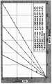
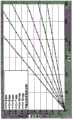
·投射的光束在任意距离处具有大于发射面(s)的尺寸(a)。该情况在所附的图15a中表示出。• The projected beam has a dimension (a) greater than the emitting surface (s) at any distance. This situation is shown in the attached Figure 15a.
·存在距投影系统的某一距离,在该距离处线的高度(a)与发射面(s)的高度相同。该情况在所附的图15b中表示出。• There is a distance from the projection system at which the height of the line (a) is the same as the height of the emitting surface (s). This situation is shown in the attached Figure 15b.
用于测量在图15a和图15b中表示为θ的散度角的方法如下:The method used to measure the divergence angle denoted θ in Figures 15a and 15b is as follows:
·针对至少两个距离(p)测量投影线的尺寸(a)。所述尺寸定义为光线的曲线的FWHM(半峰全宽)。• Measure the dimension (a) of the projection line for at least two distances (p). The dimension is defined as the FWHM (full width at half maximum) of the curve of the light.
·通过线性回归计算内插所有测量的成对值(p,a/2)的直线的方程。所述直线的方程是a/2=m·p+q;• Calculate the equation of a straight line interpolating all measured pairs of values (p, a/2) by linear regression. The equation of the straight line is a/2=m·p+q;
计算散度角θ=arctanm)。Calculate the divergence angle θ = arctanm).
以此方式计算的散度角称为半值(half-amplitude),因为它是连接投影线和发射源的两条直线包围的总的角度的一半。The divergence angle calculated in this way is called half-amplitude because it is half the total angle enclosed by the two straight lines connecting the projection line and the emission source.
上述方法用来计算由本发明的线性阅读器中的准直仪产生的散度。通过上述方法定义并计算光束在垂直于传播方向的平面中的截面的次要尺寸的散度值小于1.5°半值。在下文中,次要尺寸也将被称为“竖直”尺寸。可以理解,在当前背景中使用的术语竖直的或水平的,不反映阅读器在其使用期间在空间中的实际位置,该位置可以是任意的。The above method is used to calculate the divergence produced by the collimator in the linear reader of the present invention. The divergence value of the secondary dimension of the cross-section of the beam in the plane perpendicular to the propagation direction is defined and calculated by the above method to be less than 1.5° half-value. In the following, the secondary dimension will also be referred to as the "vertical" dimension. It will be appreciated that the terms vertical or horizontal used in the present context do not reflect the actual position of the reader in space during its use, which may be arbitrary.
因此,根据本发明,准直仪被设计为获得期望的竖直散度,也就是说,使得光线的厚度是“薄的”;束成形器被设计为使光线的强度均衡并且在水平方向上(也就是说在平行于传感器视场的主要尺寸的方向上)获得期望的角幅度。Therefore, according to the present invention, the collimator is designed to obtain the desired vertical divergence, that is, so that the thickness of the light is "thin"; the beam shaper is designed to equalize the intensity of the light and in the horizontal direction (that is, in a direction parallel to the main dimension of the sensor's field of view) to obtain the desired angular magnitude.
此外,即使在准直仪的光组的输出处光束的尺寸强烈地取决于光束在厚度方向上的散度(其如上所述小于1.5°半值,并且是准直仪的实施细节的结果),优选的是准直仪还在垂直于次要尺寸的方向的方向(水平方向)上执行源发射的光束的准直。事实上,在主要或水平方向上的准直允许通过束成形器收集更大量的功率,并因此在照明装置的光组的输出处提供更大功率的光束。为了在不沿主要方向准直光束的情况下在输出处也获得相同的功率,将有必要具有大尺寸的束成形器,其与此情况下优选需要减小线性阅读器的尺寸不兼容。Furthermore, the size of the beam even at the output of the light set of the collimator strongly depends on the divergence of the beam in the thickness direction (which is less than 1.5° half-value as mentioned above and is a result of the implementation details of the collimator) , it is preferred that the collimator also performs the collimation of the light beam emitted by the source in a direction (horizontal direction) perpendicular to the direction of the secondary dimension. In fact, collimation in the main or horizontal direction allows a greater amount of power to be collected by the beam shaper and thus provide a more powerful beam at the output of the light set of the lighting device. In order to obtain the same power at the output also without collimating the beam in the main direction, it will be necessary to have a beam shaper of large size, which is not compatible with the preferred need to reduce the size of the linear reader in this case.
在这个第一方面中,本发明可以提供一个或多个以下优选特性,无论是组合或是替代性地。In this first aspect, the present invention may provide one or more of the following preferred features, whether in combination or alternatively.
优选地,所述束成形器适合于在输出处发射准直的成形光束,其沿所述主要方向具有大体上均匀的功率。Preferably, the beam shaper is adapted to emit at the output a collimated shaped beam of substantially uniform power along the main direction.
束成形器使源发射的功率沿光束的整个长度(也就是说大体上由光束在垂直于传播方向的平面中的横截面限定的主要方向上)均衡,以便沿所述主要尺寸的光线的功率是大体上均匀的。The beam shaper equalizes the power emitted by the source along the entire length of the beam (that is to say generally in the principal direction defined by the beam's cross-section in a plane perpendicular to the direction of propagation) so that the power of the light along the principal dimension is generally uniform.
优选地,所述束成形器包括具有正焦距的透镜。Preferably, the beam shaper comprises a lens having a positive focal length.
如果束成形器包括正焦距透镜,这意味着由源发射的光束先会聚,然后在水平尺寸上发散。这允许在选择阅读器的玻璃窗的正确位置的同时,使来自光源的反射在玻璃窗上并引导到线性传感器中的光量最小。If the beam shaper includes a positive focal length lens, this means that the beam emitted by the source first converges and then diverges in a horizontal dimension. This allows selecting the correct position of the glazing of the reader while minimizing the amount of light from the light source that is reflected on the glazing and directed into the linear sensor.
优选地,所述束成形器在垂直于所述准直成形光束的所述次要尺寸的方向上是不变的,以便在所述方向上被准直的所述光束保持不被改变。Preferably, the beam shaper is invariant in a direction perpendicular to the secondary dimension of the collimated shaped beam, so that the beam collimated in that direction remains unchanged.
更优选地,束成形器的所述不变的垂直方向对应于所述准直仪输出处的所述准直光束的次要尺寸。More preferably, the constant vertical direction of the beam shaper corresponds to the secondary dimension of the collimated beam at the output of the collimator.
束成形器对准直仪输出处的准直光束的作用在束的次要尺寸方向上保持大体上不变的散度(竖直厚度保持来自准直仪输出的散度),但是沿大体上平行于视场的主要轴线的方向的方向(所谓的水平方向)使束“变宽”。考虑到视场是矩形的,束成形器在被定义在视场中的矩形的主要侧的方向上延长准直光束,并在垂直方向上使其大体上不改变。The effect of the beam shaper on the collimated beam at the collimator output maintains a substantially constant divergence in the direction of the secondary dimension of the beam (the vertical thickness maintains the divergence from the collimator output), but along the A direction parallel to the direction of the main axis of the field of view (the so-called horizontal direction) "broadens" the beam. Considering that the field of view is rectangular, the beam shaper extends the collimated beam in the direction of the major sides of the rectangle defined in the field of view and leaves it substantially unchanged in the vertical direction.
优选地,这个扩展方向不仅平行于视场的主要尺寸,而且平行于准直仪输出处的光束的主要方向。Preferably, this direction of expansion is not only parallel to the main dimension of the field of view, but also parallel to the main direction of the beam at the output of the collimator.
更优选地,所述非相干光源沿主要方向延伸,所述主要方向大体上平行于所述成形的准直光束的所述主要方向。More preferably, the incoherent light source extends in a main direction which is substantially parallel to the main direction of the shaped collimated beam.
如前所述,束成形器限定准直光束沿其“变宽”的轴线,并且这个轴线实现为使得它平行于在传感器的视场的横截面中定义的矩形的主要尺寸。As before, the beam shaper defines the axis along which the collimated beam "broadens", and this axis is implemented such that it is parallel to the major dimension of the rectangle defined in the cross-section of the sensor's field of view.
在束成形器的“变宽”轴线与准直仪的输出处的束的主要宽度方向之间存在角度的情况下,在束成形器输出处的准直成形光束将具有大于准直仪输出处的准直光束的厚度尺寸。因此,为了将准直成形光束保持在最小厚度尺寸,优选的是源的主要尺寸平行于光束沿其变宽的束成形器的轴线。In the presence of an angle between the "broadening" axis of the beam shaper and the main width direction of the beam at the output of the collimator, the collimated shaped beam at the output of the beam shaper will have a larger diameter than at the output of the collimator The thickness dimension of the collimated beam. Therefore, in order to keep the collimated shaped beam to a minimum thickness dimension, it is preferred that the major dimension of the source be parallel to the axis of the beam shaper along which the beam widens.
优选地,准直光束和成形准直光束共同的这个主要方向也平行于源的主要延伸轴。Preferably, this main direction common to the collimated beam and the shaped collimated beam is also parallel to the main axis of extension of the source.
更优选地,所述光源包括微型LED。More preferably, the light source comprises micro LEDs.
在现有技术中已知微型LED光源,诸如基于GaN技术(氮化镓)的那些微型LED光源,能够实现具有非常小尺寸的发射器芯片,如在WO 2011/111079 A1中所描述的,其适合于实现能够投射非常小的图案的阵列。具体地,在现有技术中已知,微型LED光源适用于实现具有矩形形式因素的芯片。Micro LED light sources are known in the prior art, such as those based on GaN technology (gallium nitride), enabling the realization of emitter chips with very small dimensions, as described in WO 2011/111079 A1, which Suitable for implementing arrays capable of projecting very small patterns. In particular, miniature LED light sources are known in the prior art to be suitable for realizing chips having a rectangular form factor.
更优选地,所述光源包括单个微型LED。More preferably, the light source comprises a single micro LED.
替代地,所述光源包括微型LED的线性阵列。Alternatively, the light source comprises a linear array of micro LEDs.
优选地,对于低功率范围应用,最近已经开发了提供新型光源的微型LED。微型LED通常使用标准的LED材料来建立,并且因此具有标准LED的光谱曲线、灵活性和可靠性。微型LED提供高效率以及在制造过程中集成在装置上的独特的光控制结构。在一个示例中,在装置的光生成层周围创建抛物线结构。在光脱离芯片之后,这个结构控制在光生成地点处发射的光,并比使用外部光学器件更有效率。Preferably, for low power range applications, micro LEDs have recently been developed that provide novel light sources. Micro LEDs are typically built using standard LED materials and thus have the spectral profiles, flexibility and reliability of standard LEDs. Micro LEDs offer high efficiency as well as a unique light control structure integrated on the device during fabrication. In one example, a parabolic structure is created around the light generating layer of the device. After the light leaves the chip, this structure controls the light emitted at the light generation site and is more efficient than using external optics.
在LED的设计和制造中,GaN材料的折射率与空气的折射率之间的差是高提取光效率的重大障碍。与标准组件相反,微型LED装置使用材料的这种基本特性,以增强性能。来自微型LED内的抛物线结构的侧壁的全内反射朝向提取表面聚焦光;侧壁的设计和形状被精确地控制以确保高比例的光到达垂直于界面的离开表面。这导致最小的背反射、高光提取效率和良好的束形状控制。In the design and manufacture of LEDs, the difference between the refractive index of the GaN material and that of air is a significant obstacle to high extraction light efficiency. In contrast to standard components, micro LED devices use this fundamental property of the material to enhance performance. Total internal reflection from the sidewalls of the parabolic structure within the micro-LED focuses the light towards the extraction surface; the design and shape of the sidewalls are precisely controlled to ensure that a high proportion of the light reaches the exit surface normal to the interface. This results in minimal back reflections, high light extraction efficiency and good beam shape control.
优选地,所述微型LED光源是矩形的,具有较小的第一尺寸和较长的第二尺寸。Preferably, the micro-LED light source is rectangular, having a smaller first dimension and a longer second dimension.
在两种情况下,也就是说在源实施为单个源或实施为多个源的情况下,所述光源优选地在第一方向上具有5μm与300μm之间的尺寸,更优选地具有在5μm与50μm之间的尺寸。In both cases, that is to say where the source is implemented as a single source or as multiple sources, the light source preferably has a dimension in the first direction between 5 μm and 300 μm, more preferably between 5 μm and 50 μm in size.
在两种情况下,也就是说在源实施为单个源或实施为多个源的情况下,所述光源优选地在第二方向上具有100μm与3000μm之间的尺寸,更优选地具有在100μm与1500μm之间的尺寸。In both cases, that is to say where the source is implemented as a single source or as multiple sources, the light source preferably has a dimension in the second direction between 100 μm and 3000 μm, more preferably between 100 μm and sizes between 1500 μm.
优选地,所述第一和所述第二方向彼此垂直。Preferably, said first and said second directions are perpendicular to each other.
“源的尺寸”理解为源的“有用”部分(或有用区域)的尺寸,其图像被光学器件投射。本发明还提供放置在源前面或与源接触的狭缝或孔径的使用,以形成束的形状;在此情况下,在狭缝或孔径的输出处的束的尺寸表示光的尺寸。The "size of the source" is understood to be the size of the "useful" part (or useful area) of the source, the image of which is projected by the optics. The invention also provides for the use of a slit or aperture placed in front of or in contact with the source to shape the beam; in this case the size of the beam at the output of the slit or aperture represents the size of the light.
优选地,源的主要尺寸(也称为第二尺寸或水平尺寸)在100μm与3000μm之间。较大尺寸的源将产生具有使它不适合作为输入到“适度”尺寸(例如,实施紧凑阅读器所要求的那些尺寸)的准直仪的尺寸的光束,因为大部分的功率将损失。尤其是,相当于准直光学器件的具有大尺寸的源将增加存在于准直光束中的畸变,从而远离“点光源”的理想条件移动。较小尺寸将不允许紧凑的光组产生具有用于在期望的距离处读取光学信息的足够功率的光线。Preferably, the major dimension of the source (also referred to as the second dimension or horizontal dimension) is between 100 μm and 3000 μm. Larger sized sources will produce beams of dimensions that make them unsuitable as input to "moderate" sized collimators (eg, those required to implement compact readers), since most of the power will be lost. In particular, sources with large dimensions, equivalent to collimating optics, will increase the distortion present in the collimated beam, moving away from the ideal conditions of a "point source". Smaller dimensions would not allow a compact light set to produce light with sufficient power to read optical information at the desired distance.
关于源的厚度(其是沿第一方向的尺寸),因为优选地产生的光线是“薄的”,所以由光源的实际可行性给出5μm的最低限制(理论上发射器线尽可能薄,同时保持适合于应用的发射功率)。300μm的最大限制大体上是对准直仪的焦距和投影线的期望厚度的约束的结果。With regard to the thickness of the source (which is the dimension along the first direction), since preferably the light produced is "thin", a minimum limit of 5 μm is given by the practical feasibility of the light source (theoretically the emitter line is as thin as possible, while maintaining the transmit power suitable for the application). The maximum limit of 300 μm is generally the result of constraints on the focal length of the collimator and the desired thickness of the projection line.
如图14a所示,在第一方向上的例如微型LED的光源的尺寸(即,其厚度)称为“tv”、在距离照明装置的准直仪的主平面的距离“d”处由源发射的光束的厚度称为“av”,并且准直仪的焦距称为“f”,几何光学器件保持以下等式:As shown in Figure 14a, the size (ie, its thickness) of a light source, such as a micro LED, in a first direction, called "tv", is defined by the source at a distance "d" from the principal plane of the collimator of the illuminator The thickness of the emitted beam is called "av" and the focal length of the collimator is called "f", geometric optics maintain the following equation:
tv=(f*av)/d。tv=(f*av)/d.
考虑在距离准直仪d=500mm处具有最大厚度av=10mm的线,并且准直仪的最大焦距f=15mm,光源将优选地具有最大尺寸“tv”等于:10*(15/500)=0.3mm=300μm。这个计算是纯近轴的,而由于畸变的存在实际的线的厚度要更大,并且具体地,其可以达到如前所述的15mm FWHM。Considering a line with a maximum thickness av=10mm at a distance of d=500mm from the collimator, and a maximum focal length of the collimator f=15mm, the light source will preferably have a maximum dimension "tv" equal to: 10*(15/500)= 0.3mm=300μm. This calculation is purely paraxial, whereas the actual wire thickness is greater due to the presence of distortion, and in particular it can reach 15mm FWHM as previously described.
优选地,所述准直仪(22)的焦距等于:Preferably, the focal length of the collimator (22) is equal to:
f=(tv*d)/avf=(tv*d)/av
其中,av≤15mm,并且where av≤15mm, and
d=500mm。d=500mm.
以与上述相同的方式,给定所使用的源的厚度“tv”和在距离“d”处的束的最大期望厚度“av”,则准直仪的焦距“f”必须从相同的公式f=(tv*d)/av计算。优选地,因此给定距离d=500mm并且在此距离d处光线具有厚度“av”≤15mm,并且给出非相干源的厚度“tv”,根据以上公式计算准直仪的焦距。In the same way as above, given the thickness "tv" of the source used and the maximum desired thickness "av" of the beam at distance "d", the focal length "f" of the collimator must be derived from the same formula f =(tv*d)/av calculation. Preferably, the focal length of the collimator is calculated according to the above formula, therefore given a distance d=500mm and at this distance d the ray has a thickness "av"≤15mm, and given the thickness "tv" of the incoherent source.
优选地,如提到的,该源是微型LED,因此,在公式中引入非常“薄的”“tv”。具有薄的源允许选择准直仪的仍然“合理的”焦距“f”,以在距离照明装置的光学器件半米的距离处获得合理的“薄的”光束。Preferably, as mentioned, the source is a micro LED, so a very "thin" "tv" is introduced into the formula. Having a thin source allows a still "reasonable" focal length "f" of the collimator to be chosen to obtain a reasonably "thin" beam at a distance of half a meter from the optics of the illuminator.
优选地,所述非相干光源在所述第一方向上的所述尺寸与在所述第二方向上的所述尺寸之间的比率小于或等于1/5,更优选地小于或等于1/10,甚至更优选地小于或等于1/20。Preferably, the ratio between the dimension of the incoherent light source in the first direction and the dimension in the second direction is less than or equal to 1/5, more preferably less than or equal to 1/ 10, even more preferably less than or equal to 1/20.
如前所述,优选地,需要光组来实现适合于产生具有期望尺寸的光“带”的大体上薄的“矩形”光源。As previously mentioned, a light group is preferably required to achieve a generally thin "rectangular" light source suitable for producing a "strip" of light of the desired size.
在优选实施例中,所述线性传感器包括CCD型的线性传感器。In a preferred embodiment, the linear sensor comprises a CCD type linear sensor.
替代技术是可能的,如使用CMOS传感器。Alternative technologies are possible, such as using CMOS sensors.
传感器优选地包括CCD元件的线性阵列。The sensor preferably comprises a linear array of CCD elements.
优选地,传感器的尺寸在高度上是1像素并且在长度上在1000像素与3600像素之间,更优选地在1500像素与2500像素之间,并且更优选地该长度是2500像素,即传感器是1x2500像素。Preferably, the size of the sensor is 1 pixel in height and between 1000 and 3600 pixels in length, more preferably between 1500 and 2500 pixels, and more preferably the length is 2500 pixels, ie the sensor is 1x2500 pixels.
优选地,所述光源发射绿色、蓝色或红色光的光谱中的辐射。Preferably, the light source emits radiation in the spectrum of green, blue or red light.
由于现有源上的技术限制而选择这些波长;更优选地选择绿色,因为它是传感器和人眼都对其最敏感的辐射。These wavelengths are chosen due to technical limitations on existing sources; green is more preferably chosen as it is the radiation to which both the sensor and the human eye are most sensitive.
有利地,所述准直仪的焦距小于或等于15mm,更优选地小于或等于5mm。Advantageously, the focal length of the collimator is less than or equal to 15 mm, more preferably less than or equal to 5 mm.
准直仪的焦距f的最大限制由包括准直仪的透镜或多个透镜的实际可行性给出。最大限制由准直仪自身的尺寸给出,也就是说,由线性阅读器是紧凑型的要求给出。The maximum limit to the focal length f of the collimator is given by the practical feasibility of including the lens or lenses of the collimator. The maximum limit is given by the size of the collimator itself, that is, by the requirement that the linear reader be compact.
实际上,准直仪优选地满足以下参数:In practice, the collimator preferably satisfies the following parameters:
·准直仪的宽度(也就是说,其尺寸中的在对应于束的主要尺寸、垂直于光束传播方向的方向上的一个尺寸)优选地≤15mm,更优选地小于8mm。• The width of the collimator (that is, one of its dimensions in a direction corresponding to the main dimension of the beam, perpendicular to the beam propagation direction) is preferably ≤ 15 mm, more preferably less than 8 mm.
ο由准直仪的实际可行性给出最小限制;ο Minimum constraints given by the practical feasibility of the collimator;
ο最大限制等于照明装置的总宽度;在此情况下,为了实现紧凑的装置选择15mm的最大宽度。ο The maximum limit is equal to the total width of the lighting device; in this case, a maximum width of 15mm was chosen for a compact device.
·准直仪的高度(也就是说,其尺寸中的在垂直于光束传播、垂直于上述方向并对应于束的次要尺寸的方向上的一个尺寸)优选地≤11mm,更优选地小于8mm。The height of the collimator (that is, one of its dimensions in a direction perpendicular to the beam propagation, perpendicular to the above-mentioned direction and corresponding to the secondary dimension of the beam) is preferably ≤ 11 mm, more preferably less than 8 mm .
ο由准直仪的实际可行性给出最小限制;ο Minimum constraints given by the practical feasibility of the collimator;
ο最大限制等于照明装置的总高度;在此情况下,为了实现紧凑的装置选择11mm的最大高度。ο The maximum limit is equal to the total height of the lighting device; in this case, a maximum height of 11 mm was chosen in order to achieve a compact device.
·深度(也就是说其尺寸中的在光束传播方向上的一个尺寸)D1:Depth (that is to say one of its dimensions in the beam propagation direction) D1 :
ο由透镜的实际可行性给出最小限制,ο is given the minimum limit by the practical feasibility of the lens,
ο由照明器的总深度和束成形器的厚度(D2)给出最大限制。2个厚度的总和必须小于模块的总深度(D1+D2≤15mm)。在此情况下,为了实现紧凑的装置选择15mm的最大深度。ο The maximum limit is given by the overall depth of the illuminator and the thickness of the beam shaper (D2) . The sum of the 2 thicknesses must be less than the total depth of the module (D1 +D2 ≤15mm). In this case, a maximum depth of 15mm was chosen in order to achieve a compact device.
类似地,束成形器优选地设置有以下参数:Similarly, the beam shaper is preferably provided with the following parameters:
·束成形器的宽度(也就是说,其尺寸中的在对应于束的主要尺寸、垂直于光束传播方向的方向上的一个尺寸)优选地≤15mmThe width of the beam shaper (that is, one of its dimensions in a direction corresponding to the main dimension of the beam, perpendicular to the beam propagation direction) is preferably ≤ 15 mm
ο由束成形器的实际可行性给出最小限制;。ο The minimum constraints are given by the practical feasibility of the beam shaper; .
ο最大限制等于照明装置的总宽度。ο The maximum limit is equal to the total width of the lighting fixture.
·束成形器的高度(也就是说,其尺寸中的在垂直于光束传播、垂直于上述方向并对应于光束的次要尺寸的方向上的一个尺寸)优选地≤11mmThe height of the beam shaper (that is, one of its dimensions in a direction perpendicular to the beam propagation, perpendicular to the above-mentioned direction and corresponding to the secondary dimension of the beam) is preferably ≤ 11 mm
ο由束成形器的实际可行性给出最小限制;ο minimal constraints given by the practical feasibility of the beam shaper;
ο最大限制等于照明装置的总高度。ο The maximum limit is equal to the total height of the lighting fixture.
·深度(也就是说其尺寸中的在束传播方向上的一个尺寸)D2:Depth (that is to say one of its dimensions in the beam propagation direction) D2 :
ο由束成形器的实际可行性给出最小限制,ο the minimum constraints given by the practical feasibility of the beam shaper,
ο由照明装置的总深度和准直仪的厚度(D1)给出最大限制。2个厚度的总和必须小于照明装置的总深度(D1+D2≤15mm)。ο The maximum limit is given by the total depth of the illuminator and the thickness of the collimator (D1 ). The sum of the 2 thicknesses must be less than the total depth of the lighting device (D1 +D2 ≤ 15mm).
更优选地,所述准直仪的所述焦距在1mm与6mm之间。More preferably, the focal length of the collimator is between 1 mm and 6 mm.
在优选实施例中,所述准直仪与所述光源之间的距离在0mm与15mm之间,更优选地在0mm与10mm之间,甚至更优选地,该距离小于或等于3mm。In a preferred embodiment, the distance between the collimator and the light source is between 0mm and 15mm, more preferably between 0mm and 10mm, even more preferably the distance is less than or equal to 3mm.
后焦距(BFL-准直仪与光源之间的距离)优选地在所述间隔内,其中,可以通过将准直仪放置为接触光源来获得最小限制,而由可以实施的最大焦距给出最大限制。The back focal length (the distance between the BFL-collimator and the light source) is preferably within the interval, wherein the minimum limit can be obtained by placing the collimator in contact with the light source, while the maximum is given by the maximum focal length that can be implemented. limit.
有利地,所述准直仪的最大厚度和所述束成形器在所述束的传播的所述方向上的最大厚度的总和小于15mm。Advantageously, the sum of the maximum thickness of the collimator and the maximum thickness of the beam shaper in the direction of propagation of the beam is less than 15 mm.
准直仪和/或束成形器的厚度被定义为在由光源发射的光束的传播方向上所述准直仪和/或束成形器的尺寸。所述厚度被最小化,以使线性阅读器紧凑。The thickness of the collimator and/or beam shaper is defined as the dimension of the collimator and/or beam shaper in the direction of propagation of the light beam emitted by the light source. The thickness is minimized to make the linear reader compact.
在优选实施例中,以具有高折射率的材料实现所述准直仪和/或所述束成形器。优选地,所述折射率高于1.5。In a preferred embodiment, the collimator and/or the beam shaper are implemented in a material having a high refractive index. Preferably, the refractive index is higher than 1.5.
优选地,束成形器和/或准直仪的构成材料是例如具有等于1.59的折射率的塑料,如聚碳酸酯,其高于具有等于1.49的折射率的如PMMA的标准丙烯酸塑料。Preferably, the material of construction of the beam shaper and/or the collimator is eg a plastic with a refractive index equal to 1.59, such as polycarbonate, which is higher than a standard acrylic plastic such as PMMA with a refractive index equal to 1.49.
高折射率允许限制束成形器和/或准直仪的表面曲率,同样以便使这两个光学装置的机械体积最小化并满足紧凑度的约束。The high index of refraction allows limiting the surface curvature of the beam shaper and/or collimator, also in order to minimize the mechanical bulk of these two optical devices and meet compactness constraints.
优选地,所述光学接收轴线和所述光学照明轴线是平行的并放置在小于15mm并且更优选地小于10mm的距离处。Preferably, the optical reception axis and the optical illumination axis are parallel and placed at a distance of less than 15mm and more preferably less than 10mm.
根据替代实施例,光学接收轴线和光学照明轴线是会聚的。更优选地,光学接收轴线和光学照明轴线形成包括在1°与5°之间的更优选地大约1.5°的角度。According to an alternative embodiment, the optical reception axis and the optical illumination axis are converging. More preferably, the optical reception axis and the optical illumination axis form an angle comprised between 1° and 5°, more preferably about 1.5°.
为了将投影线相对于接近阅读器的视场的错位降低到最小,优选的是接收装置和照明装置放置得尽可能彼此接近,并且优选地,中心到中心的距离小于15mm。To minimize misalignment of the projection line relative to the field of view close to the reader, it is preferred that the receiving device and the illuminating device are placed as close to each other as possible, and preferably the center-to-center distance is less than 15mm.
此外,接收装置的视场和由照明装置发射的光束形成的线优选地重叠尽可能宽的距离范围。当距离阅读器的短距离处,如果照明装置和接收装置这两个装置相互间隔远,则视场和光线将不重叠。因此,光学接收轴线和光学照明轴线的位置理想地应该是一致的。这优选地限制了照明装置和接收装置这两个的光组的尺寸,以便小尺寸将限制中心到中心的距离。Furthermore, the field of view of the receiving device and the line formed by the light beam emitted by the illuminating device preferably overlap as wide a distance range as possible. At short distances from the reader, if the two devices, the illuminating device and the receiving device, are far apart from each other, the fields of view and rays will not overlap. Therefore, the positions of the optical reception axis and the optical illumination axis should ideally coincide. This preferably limits the size of the light sets for both the illuminating device and the receiving device, so that the small size will limit the center-to-center distance.
优选地,所述准直仪适合于在输出处发射准直光束,该准直光束在次要尺寸上具有小于1°半值的散度。Preferably, the collimator is adapted to emit a collimated beam at the output, the collimated beam having a divergence in the secondary dimension of less than 1° half value.
如前所述,希望获得非常薄的发射光带。As previously mentioned, it is desirable to obtain very thin emission bands.
有利地,所述视场具有大体上矩形的横截面,其限定大体上互相垂直的所述主要尺寸和所述次要尺寸。Advantageously, said field of view has a substantially rectangular cross-section defining said major dimension and said minor dimension which are substantially perpendicular to each other.
因为由照明装置发射的光束具有大于另一尺寸的一个尺寸,从而在过程中实现光条,因此接收装置的视场的尺寸类似地具有矩形横截面,其也形成“条状”横截面。Because the light beam emitted by the illuminating device has one dimension larger than the other, realizing a light bar in the process, the dimensions of the receiving device's field of view similarly have a rectangular cross-section, which also forms a "striped" cross-section.
按照以上讨论,光线和视场优选地叠加通过本发明的线性阅读器的大部分有用读取范围。As discussed above, the light ray and field of view preferably superimpose most of the useful read range through the linear reader of the present invention.
更优选地,所述视场沿所述视场的所述次要方向小于0.5°半值。More preferably, the field of view is less than 0.5° half value along the secondary direction of the field of view.
以此方式,光线的尺寸和视场的尺寸在具阅读器的宽范围的距离处大体上一致。In this way, the size of the light rays and the size of the field of view are generally consistent over a wide range of distances with the reader.
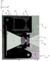
有利地,阅读器包括底架,所述接收装置和所述照明装置邻近限定安装基部的所述底架安装,所述线性传感器和所述光源大体上垂直于所述安装基部布置。Advantageously, the reader comprises a chassis, said receiving means and said illuminating means being mounted adjacent to said chassis defining a mounting base, said linear sensor and said light source being arranged substantially perpendicular to said mounting base.
底架是阅读器的各个组件如照明装置和接收装置组装在其上的支撑件。其限定由互相垂直的两个轴线-X和Z给出的安装平面。各个装置例如通过粘合平行于这个平面(下文中称为水平面)被固定的基部上。但是,应该理解,所述平面(以及因此的基底)还可以相对于水平面倾斜;特别是在阅读器的使用过程中;该平面移动以使阅读器本身相对于要读取的光学信息定位在最佳位置,以便底架可以采用可及时改变的空间中的位置。术语“水平面”仅用于方便作为参照系。The chassis is the support on which the various components of the reader, such as the lighting device and the receiving device, are assembled. It defines a mounting plane given by two mutually perpendicular axes -X and Z. The respective devices are fixed on a base parallel to this plane (hereinafter referred to as the horizontal plane), for example by gluing. It should be understood, however, that the plane (and thus the substrate) may also be inclined with respect to the horizontal plane; in particular during use of the reader; the plane is moved to position the reader itself at the highest position relative to the optical information to be read the optimal position so that the chassis can adopt a position in space that can be changed in time. The term "horizontal plane" is used for convenience only as a frame of reference.
此外,术语“平行”和“垂直”不在绝对意义上被理解,而在各个组件的组装和对齐的潜在误差内。因此,当说两个元件平行或垂直时,要理解为在现有技术中已知的并在参考技术领域中普遍的误差范围内。Furthermore, the terms "parallel" and "perpendicular" are not to be understood in an absolute sense, but rather within the potential error of assembly and alignment of the various components. Thus, when two elements are said to be parallel or perpendicular, it is to be understood to be within a range of error known in the art and common in the art of reference.
线性传感器和光源都以大体上垂直于安装平面的方式安装。替代地,它们可以以相对于垂直于安装平面的线成高达20°至30°角的角度安装。如前所述,传感器的光学轴线和源的光学轴线是共面的,并且优选地,由两个轴线形成的所述平面也平行于安装平面。以此方式,线性传感器和光源优选地相对于底架的安装平面处于大体上相同的高度,也就是说,它们大体上处于沿垂直于限定在底架(例如,基底)上的安装平面的轴线的相同距离。Both the linear sensor and the light source are mounted substantially perpendicular to the mounting plane. Alternatively, they can be mounted at an angle of up to 20° to 30° relative to a line perpendicular to the mounting plane. As before, the optical axis of the sensor and the optical axis of the source are coplanar, and preferably the plane formed by the two axes is also parallel to the mounting plane. In this way, the linear sensor and light source are preferably at substantially the same height relative to the mounting plane of the chassis, that is, they are generally located along an axis perpendicular to the mounting plane defined on the chassis (eg, base) the same distance.
更优选地,所述线性传感器固定在大体上垂直于所述安装基部安装的印刷电路板上,所述线性传感器使其主要取向方向大体上平行于所述安装基部的。More preferably, the linear sensor is fixed on a printed circuit board mounted substantially perpendicular to the mounting base, the linear sensor having its main orientation direction substantially parallel to the mounting base.
有利地,线性传感器以矩形配置布置。其主要取向方向大体上平行于底架的安装平面。此外,传感器优选地安装在印刷电路或PCB上,从而被方便地供电和控制。Advantageously, the linear sensors are arranged in a rectangular configuration. Its main orientation direction is substantially parallel to the mounting plane of the chassis. Furthermore, the sensors are preferably mounted on a printed circuit or PCB so that they can be easily powered and controlled.
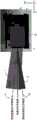
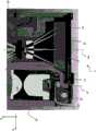
优选地,所述照明装置包括盒式壳体,所述盒式壳体包含所述准直仪和所述束成形器,所述盒式壳体包括或适合于连接到用于调节围绕所述盒式壳体的轴线旋转的至少一个角度的装置。Preferably, the lighting device comprises a cassette housing containing the collimator and the beam shaper, the cassette housing comprising or adapted to be connected to a housing for adjustment around the The axis of the cassette housing rotates by at least one angle.
包括准直仪和束成形器的照明装置的光组优选地组装在盒式壳体内。如前所述,因为准直仪和束成形器相对于它们的相互位置具有宽的容差,所以它们可以预先组装在诸如盒式壳体的机械结构中,而不用进一步检查。The light group of the illumination device including the collimator and beam shaper is preferably assembled within a cassette housing. As previously mentioned, because the collimator and beam shaper have wide tolerances with respect to their mutual positions, they can be pre-assembled in mechanical structures such as cassette housings without further inspection.
优选地,首先将束成形器固定到盒式壳体上,并且然后朝向和远离束成形器平移准直仪,直到到达正确位置。Preferably, the beam shaper is first secured to the cassette housing and then the collimator is translated towards and away from the beam shaper until the correct position is reached.
随后,优选地执行与光源的对齐,光源进而优选地安装在印刷电路(PCB)上。Subsequently, an alignment with the light source is preferably performed, which in turn is preferably mounted on a printed circuit (PCB).
优选地,源安装在其上的PCB也垂直于由底架限定的安装基部。优选地,源的PCB和传感器的PCB互相平行,并排列在交错的平面上。Preferably, the PCB on which the source is mounted is also perpendicular to the mounting base defined by the chassis. Preferably, the PCB of the source and the PCB of the sensor are parallel to each other and arranged in staggered planes.
为了正确地执行照明装置与接收装置之间的对齐以便针对离线性阅读器尽可能大的距离范围使后者的视场大体上重叠在由前者发射的光束限定的线上,优选的是主动地执行这些装置之间的对齐。通过保持接收装置固定,而根据需要相对于接收装置旋转照明装置来有利地执行该对齐。In order to correctly perform the alignment between the illuminating device and the receiving device so that the field of view of the latter substantially overlaps the line defined by the beam emitted by the former for the greatest possible distance range of the linear reader, it is preferable to actively Perform alignment between these devices. This alignment is advantageously performed by keeping the receiving device stationary while rotating the lighting device relative to the receiving device as required.
可以借助于盒式壳体外部的装置,如外部3D操纵器,借助于盒式壳体本身的适当的配置(其可以借助于外部操纵器再次移动,但是由于其几何结构在底架上滑动和/或旋转)执行围绕一个或多个轴线的这种旋转,从而使对齐更简单。This can be done by means of means external to the cassette housing, such as an external 3D manipulator, by means of a suitable configuration of the cassette housing itself (which can be moved again by means of the external manipulator, but due to its geometry slides on the chassis and and/or rotation) to perform such rotation about one or more axes, thereby making alignment simpler.
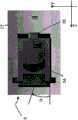
更优选地,所述照明装置包括盒式壳体,所述盒式壳体包括所述准直仪和所述束成形器,所述盒式壳体包括该盒式壳体以其固定到所述底架上的至少一个安装壁,所述安装壁接触所述安装基部,并且具有允许围绕至少一个笛卡尔轴旋转所述盒式壳体的几何结构。More preferably, the lighting device includes a box housing including the collimator and the beam shaper, the box housing including the box housing to which it is fixed. At least one mounting wall on the chassis, the mounting wall contacts the mounting base, and has a geometry that allows rotation of the cassette housing about at least one Cartesian axis.
甚至更优选地,所述底架包括适合于与所述盒式壳体的安装壁的所述几何结构结合的基座。Even more preferably, the chassis includes a base adapted to integrate with the geometry of the mounting wall of the cassette housing.
在此实施例中,在安装期间,盒式壳体靠在底架的安装基部上,但不固定到其上。盒式壳体的壁的几何结构使得由于壁本身的特定几何结构该盒式壳体本身可以在安装基部上容易地旋转或滑动。In this embodiment, during installation, the cassette housing rests on, but is not secured to, the mounting base of the chassis. The geometry of the walls of the cassette housing allows the cassette itself to be easily rotated or slid on the mounting base due to the specific geometry of the walls themselves.
例如,几何结构包括突起,例如,帽,其形状结合到实现在安装基部中的凹陷,例如,基座。突起的壁与凹陷的壁之间的相互滑动允许整个盒式壳体所需的旋转。For example, the geometry includes a protrusion, eg a cap, the shape of which is coupled to a recess implemented in the mounting base, eg a base. The mutual sliding between the raised and recessed walls allows the required rotation of the entire cassette housing.
替代地,“突起”几何结构存在于底架的安装基部中,而凹陷或基座实现在盒式壳体中,并且更精确地实现在其壁中的一个上。上述相同形状结合允许必要的旋转。Alternatively, the "protrusion" geometry exists in the mounting base of the chassis, while the recess or base is implemented in the cassette housing, and more precisely on one of its walls. The same shape combination described above allows the necessary rotation.
甚至更优选地,所述安装壁具有允许所述盒式壳体围绕互相垂直的至少两个笛卡尔轴线旋转的几何结构。Even more preferably, the mounting wall has a geometry that allows the cassette housing to rotate about at least two Cartesian axes that are perpendicular to each other.
在实施例中,可以借助包括照明装置的光组的盒式壳体的壁的适合的几何结构来获得这种旋转。甚至更优选地,所述安装壁设置有面向所述底架的所述安装基部的凸形或凹形形状。In an embodiment, this rotation may be obtained by means of a suitable geometry of the walls of the box housing comprising the light group of the lighting device. Even more preferably, the mounting wall is provided with a convex or concave shape facing the mounting base of the chassis.
具有面向安装基部的凸形或凹形形状的所述壁允许围绕平行和垂直于安装平面的照明装置的各种轴线的更简单旋转。Said wall having a convex or concave shape facing the mounting base allows easier rotation about various axes of the lighting device both parallel and perpendicular to the mounting plane.
凸形或凹形形状可以是单的或双的;例如,根据希望围绕其获得盒式壳体的潜在旋转的笛卡尔轴线的数量,所述壁可以包括圆柱壳的一部分(在单个方向上成凸形或凹形)或球形表面的一部分(在两个方向上成凸形或凹形)。The convex or concave shape may be single or double; for example, the wall may comprise a portion of a cylindrical shell (shaped in a single direction), depending on the number of Cartesian axes about which it is desired to obtain potential rotation of the cassette shell. convex or concave) or part of a spherical surface (convex or concave in both directions).
进而,底架包括互补的凸形或凹形基座:在盒式壳体具有朝向安装平面凸起的壁如突出的球形壁的情况下;基座可以例如包括用于使球面停留和旋转的环。替代地,底架可以包括凹陷或基座形式的球形壁,其以这样的方式配置:从盒式壳体突伸出的球形表面的壁在底架上的凹陷的球形表面的壁上滑动。Furthermore, the chassis comprises a complementary male or female base: in the case of the cassette housing having a wall that is convex towards the mounting plane, such as a protruding spherical wall; the base may for example comprise a pedestal for resting and rotating the spherical surface ring. Alternatively, the chassis may comprise a spherical wall in the form of a recess or base configured in such a way that the spherical surface wall protruding from the cassette housing slides on the recessed spherical surface wall on the chassis.
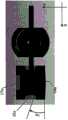
优选地,所述盒式壳体包括两个轴向相对的球形帽。Preferably, the cassette housing includes two axially opposed spherical caps.
更优选地,这两个球形帽是同一球面的部分,即,它们是单个球面的部分,并且因此具有相同的中心。这两个球形帽被容纳在例如实现在底架上的具有几何匹配形状的对应基座中。More preferably, the two spherical caps are part of the same spherical surface, ie they are part of a single spherical surface and therefore have the same center. The two spherical caps are accommodated in corresponding bases with geometrically matching shapes, eg realized on the chassis.
优选地,底架包括压缩元件,所述压缩元件接触一个所述球形帽,以抵靠基座压缩帽,以便防止相互滑动。Preferably, the chassis includes compression elements that contact one of the spherical caps to compress the caps against the base to prevent sliding against each other.
优选地,底架包括这样的元件,当该元件被固定到底架的剩余部分上时,将帽压缩在基座上,以便帽不再可能在基座中旋转,并将照明装置“封锁(blocked)”在选定的位置中。Preferably, the base frame includes an element which, when fastened to the remainder of the base frame, compresses the cap on the base so that it is no longer possible for the cap to rotate in the base and "blocks the lighting" )" in the selected location.
这种元件可以是例如盖状物(cover),其插在从底架延伸的突出或突起中,并且然后固定。更优选地,在固定之后,盖状物和基部大体上互相平行。Such an element may be, for example, a cover, which is inserted in a protrusion or protrusion extending from the chassis, and is then secured. More preferably, after fixation, the lid and base are substantially parallel to each other.
优选地,接触的元件的表面,例如,(多个)球形帽的表面和基座或盖状物的表面,是粗糙的,以便当这些表面一个在另一个上滑动时存在相对高的摩擦。Preferably, the surfaces of the contacting elements, eg the surface of the spherical cap(s) and the surface of the base or cover, are rough so that there is a relatively high friction when these surfaces slide one over the other.
优选地,所述盒式壳体包括匹配所述底架中的两个对应的凹形基座的两个球形帽。Preferably, the cassette housing includes two spherical caps that mate with two corresponding concave bases in the chassis.
例如,盖状物同样包括具有匹配一个帽的几何形状的基座,以执行围绕任意笛卡尔轴的简单旋转。For example, the cap also includes a base having a geometry that matches a cap to perform simple rotation about any Cartesian axis.
有利地,所述底架包括集成的插孔,以容纳所述接收装置的所述光组。Advantageously, the chassis includes an integrated socket to accommodate the light group of the receiving device.
在一个实施例中,所述底架包括集成的插孔,以容纳接收装置的光组。然后可以例如容纳在盒式壳体中的所述光组被插入在所述壳体中并牢固地安装在底架上。In one embodiment, the chassis includes an integrated receptacle to accommodate the light group of the receiving device. The light group, which may for example be accommodated in a box-type housing, is then inserted into the housing and securely mounted on the chassis.
在照明装置与接收装置之间的上述主动对齐中,后者因此保持牢固地“静止”在由底架限定的参考平面(安装平面)上。In the above-described active alignment between the lighting device and the receiving device, the latter thus remain firmly "resting" on the reference plane (mounting plane) defined by the chassis.
更优选地,所述插孔包括弹性材料的环或套管,该环或套管接触从所述传感器面向外的所述光组的末端中的一个。More preferably, the receptacle comprises a ring or sleeve of elastomeric material that contacts one of the ends of the light set facing outward from the sensor.
当在与底架本身一体形成的插孔内滑动接收装置的光组的盒式壳体(例如,其由与底架相同的金属制成)时,由于两个组件之间的摩擦,可能形成灰尘或其他残留物。所述残留物可以潜在地接触位于插孔底部处的线性传感器的表面。为了防止插孔中(并且优选地在其面向传感器的一个端部处)的这种沉积,存在用作用于由光组的盒式壳体的壁与插孔的壁的摩擦产生的任何颗粒的垫圈的环(如橡胶环),从而阻止残留物并防止它落在线性传感器上。When sliding the box housing of the light group of the receiving device (for example, made of the same metal as the chassis) within the receptacle formed integrally with the chassis itself, due to friction between the two components, it is possible to form dust or other residues. The residue can potentially contact the surface of the linear sensor at the bottom of the socket. In order to prevent this deposition in the receptacle (and preferably at its one end facing the sensor), there is used for any particles generated by friction of the walls of the cassette housing of the light group with the walls of the receptacle. The ring of the gasket (such as a rubber ring), thus blocking the residue and preventing it from falling on the linear sensor.
代替环,优选地,接收装置具有在传感器周围的内壁,其被弹性套管覆盖。Instead of a ring, the receiving device preferably has an inner wall around the sensor, which is covered by an elastic sleeve.
优选地,套管覆盖插孔的内壁的大部分,并且是弹性的和黑色的。Preferably, the sleeve covers most of the inner wall of the socket and is elastic and black.
在所述第二方面中,本发明涉及一种相对于照明装置主动对齐接收装置或相对于接收装置主动对齐照明装置的方法。In said second aspect, the present invention relates to a method of actively aligning a receiving device relative to a lighting device or a method of actively aligning a lighting device relative to a receiving device.
这种方法应用到线性传感器,并且更通常地还应用到具有适合于读取二维光学信息的矩阵传感器的阅读器。所述方法允许具有非常高的精确度。例如,在上述线性阅读器的情况下,假设投影的光线尺寸相对于阅读器的视场减小,可见可以当前技术实现的机械容差如何不足以对齐照明装置和接收这两个装置以使视场和光线按需要重叠。This approach applies to linear sensors, and more generally also to readers with matrix sensors suitable for reading two-dimensional optical information. The method allows a very high degree of precision. For example, in the case of the linear reader described above, assuming the projected ray size is reduced relative to the reader's field of view, it can be seen how the mechanical tolerances achievable with current technology are not sufficient to align the illuminator and receive the two so that the view Fields and rays overlap as desired.
在所述第二方面中,本发明涉及主动对齐包括传感器的接收装置和包括适合于发射光束的至少一个光源的照明装置的方法,所述方法包括:In said second aspect, the present invention relates to a method of actively aligning a receiving device comprising a sensor and a lighting device comprising at least one light source adapted to emit a light beam, the method comprising:
-组装所述接收装置;- assembling the receiving device;
-将所述接收装置稳定地固定到底架上;- stably fixing the receiving device to the chassis;
-使所述照明装置的光组相对于所述光源主动对齐;- actively aligning the light group of the lighting device with respect to the light source;
-将所述照明装置的所述光组固定地连接到所述光源;- fixedly connecting the light group of the lighting device to the light source;
-使所述照明装置相对于所述接收装置主动对齐;并且- actively aligning the lighting device relative to the receiving device; and
-将所述照明装置稳定地固定到所述底架上。- Stable fixation of the lighting device to the chassis.
在光学信息的阅读器中,希望获得借助于照明装置的光组获得的光线与接收装置的视场之间的对齐。In a reader of optical information, it is desirable to obtain an alignment between the light rays obtained by means of the light group of the illuminating device and the field of view of the receiving device.
然而考虑到构造容差,实际情况可能呈现出三类误差:However, considering the construction tolerance, the actual situation may exhibit three types of errors:
1)偏移:光线未叠加在传感器看到的光线上。当照明装置的光学平面不平行于接收装置的光学平面时产生偏移。1) Offset: The light is not superimposed on the light seen by the sensor. The offset occurs when the optical plane of the illuminating device is not parallel to the optical plane of the receiving device.
照明装置的光学平面被定义为由照明装置的光学轴线和在垂直于束传播的方向上由照明装置发射的束的主要取向方向产生的平面。其大体上上是照明装置发射的光束位于首次近似的平面。The optical plane of a lighting device is defined as the plane resulting from the optical axis of the lighting device and the main orientation direction of the beam emitted by the lighting device in a direction perpendicular to the beam propagation direction. It is essentially the plane in which the light beam emitted by the lighting device is located for the first approximation.
类似地,接收装置的光学平面被定义为由接收装置的光学轴线和沿纵向截面的接收装置的工作场的主要取向方向产生的平面。其大体上是工作场位于初次近似的平面。Similarly, the optical plane of the receiving device is defined as the plane resulting from the optical axis of the receiving device and the main orientation direction of the working field of the receiving device along the longitudinal section. It is generally the plane in which the workplace lies in the first approximation.
如果两个平面彼此成角度并且不平行则产生偏移误差,特别是由两个平面的交叉限定的直线大体上垂直于两个装置的光学轴线。例如,在根据本发明第一方面的上述成像器型线性阅读器的情况下,优选的是获得两个平面之间的小于±0.1°的角,而在不主动对齐的情况下机械容差允许达到大约±3.5°的精度。Offset errors arise if the two planes are angled to each other and not parallel, in particular the line defined by the intersection of the two planes is substantially perpendicular to the optical axes of the two devices. For example, in the case of the above-described imager-type linear reader according to the first aspect of the invention, it is preferable to obtain an angle between the two planes of less than ±0.1°, while the mechanical tolerance allows without active alignment Accuracy of approximately ±3.5° is achieved.
2)倾斜:同样在此情况下,由照明装置限定的光学平面相对于由接收装置限定的光学平面旋转。在此情况下,由两个平面的交叉限定的直线大体上平行于两个装置的光学轴线。2) Tilt: Also in this case, the optical plane defined by the illuminating means is rotated relative to the optical plane defined by the receiving means. In this case, the line defined by the intersection of the two planes is substantially parallel to the optical axes of the two devices.
例如,在根据本发明第一方面的上述成像器型线性阅读器的情况下,优选的是获得两个平面之间的小于±0.1°的角,而在不主动对齐的情况下机械容差允许达到大约±1.5°的精度。For example, in the case of the above-described imager-type linear reader according to the first aspect of the invention, it is preferable to obtain an angle between the two planes of less than ±0.1°, while the mechanical tolerance allows without active alignment Accuracy of approximately ±1.5° is achieved.
3)散焦:光线比期望的厚并且不清晰。这在光源相对于准直仪位于错误的距离处或者相对于束成形器旋转时产生。换句话说,光的主取向方向与束成形器沿其延伸准直仪输出处的准直束的轴线的方向不一致。3) Defocus: The light is thicker than expected and not sharp. This occurs when the light source is located at the wrong distance relative to the collimator or rotated relative to the beam shaper. In other words, the main orientation direction of the light does not coincide with the direction along which the beam shaper extends the axis of the collimated beam at the output of the collimator.
例如,在根据本发明第一方面的上述成像器型线性阅读器的情况下,优选的是获得相对于光源的准直仪位置的小于±10μm的误差(相对短的焦距的结果)以及小于±1°的旋转误差,这些误差仅可通过主动对齐实现。For example, in the case of the above-described imager-type linear reader according to the first aspect of the present invention, it is preferable to obtain an error of less than ±10 μm (a result of a relatively short focal length) of the collimator position with respect to the light source and less than ±10 μm 1° rotation errors, which can only be achieved with active alignment.
因此,申请人已经确定,类似的要求的容差可以借助于接收装置和照明装置的主动对齐(包括,例如,本发明第一方面中所述的成像器型线性阅读器)来实现。Accordingly, the applicants have determined that similar required tolerances can be achieved by means of active alignment of the receiving device and the illuminating device (including, for example, an imager-type linear reader as described in the first aspect of the present invention).
所提出的对齐的解决方案利用选择的光学结构的特性,以尽可能地减少需要主动调整的参数的数量。The proposed alignment solution exploits the properties of selected optical structures to minimize the number of parameters that need to be actively tuned.
在下面解释光学装置中的一些组件的“主动”对齐与“被动”对齐之间的差异。在当前说明书和权利要求书中,被动对齐定义为仅基于包括光学装置的组件的机械接口对齐,连同它们的容差。另一方面,当基于组装阶段期间的对齐质量的一个或多个参数的评估时,对齐称为是主动对齐,其提供组件之间的相对移动。评估可以借助于仪器进行,也就是说借助于特别设计的测量仪器自动进行,或手动(例如视觉),或手动并同时借助于仪器进行。The differences between "active" and "passive" alignment of some components in an optical device are explained below. In the present specification and claims, passive alignment is defined as alignment based solely on the mechanical interface of the components comprising the optics, together with their tolerances. Alignment, on the other hand, is referred to as active alignment when it is based on the evaluation of one or more parameters of alignment quality during the assembly phase, which provides relative movement between components. The evaluation can be carried out with the aid of an instrument, that is to say automatically with the aid of specially designed measuring instruments, or manually (eg visually), or both manually and simultaneously with the aid of an instrument.
接收装置在根据本发明的方法的第一阶段中组装。接收装置优选地具有用于正确地接收信号以在传感器上正确地形成光学信息图像的光组。所述光组被动地对齐,然后组装在例如盒式壳体中。The receiving device is assembled in the first stage of the method according to the invention. The receiving device preferably has a light set for correctly receiving the signal to correctly form an image of the optical information on the sensor. The light sets are passively aligned and then assembled, for example, in a box-type housing.
然后所述盒式壳体附接到底架上,例如,成像器型线性阅读器的底架,将底架和接收装置的光组便成单个块,其在随后的主动对齐中用作参照系。在此阶段中,传感器的接收装置的光组对齐。The cassette housing is then attached to a chassis, such as that of an imager-type linear reader, to combine the chassis and the light of the receiver into a single block, which is used as a frame of reference in subsequent active alignment . During this phase, the light groups of the receiving means of the sensor are aligned.
替代地,接收装置的盒式壳体是底架本身的集成部分。因此,当接收装置的盒式壳体集成到底架上时还执行“永久固定”步骤。Alternatively, the cassette housing of the receiving device is an integral part of the chassis itself. Therefore, a "permanent fixing" step is also performed when the cassette housing of the receiving device is integrated into the chassis.
然后组装照明装置的光组。这种对齐是被动的。优选地,照明装置的光组也被插在盒式壳体中。替代地,仅部分光学器件的对齐是被动的,并且其余的是主动的。The light group of the lighting device is then assembled. This alignment is passive. Preferably, the light group of the lighting device is also inserted in the cassette housing. Alternatively, the alignment of only some of the optics is passive, and the rest is active.
然后在组装的光学器件与例如安装在PCB上的光源之间进行的对齐优选地是主动的。The alignment between the assembled optics and a light source mounted eg on a PCB is then preferably active.
替代地,在主动对齐步骤中一起执行照明装置的光组的对齐和光源的对齐。Alternatively, the alignment of the light groups of the lighting device and the alignment of the light sources are performed together in an active alignment step.
在对齐之后,例如,通过将承载传感器的PCB固定到包含光学器件的盒式壳体上来使照明装置的光组和光源彼此连接。After alignment, the light group and the light source of the lighting device are connected to each other, for example by fixing the PCB carrying the sensor to the box housing containing the optics.
优选地,光组被粘合到盒式壳体上,光源被焊接到PCB上,然后将PCB固定到盒式壳体的端部上。Preferably, the light group is glued to the box housing, the light source is soldered to the PCB, and the PCB is then secured to the end of the box housing.
然后通过放置照明装置并相对于接收装置对齐照明装置进行主动对齐的第二阶段,同时打开两个装置并操作,以允许监测这些装置之间的对齐质量。A second stage of active alignment is then performed by placing the illuminator and aligning the illuminator relative to the receiver, turning on both devices simultaneously and operating to allow monitoring of the quality of the alignment between these devices.
在已经实现了期望的对齐之后,照明装置也永久地固定到底架上。The lighting device is also permanently fixed to the chassis after the desired alignment has been achieved.
通过保持接收装置固定使照明装置相对于接收装置光学对齐并连接到底架上的选择是照明装置的尺寸相对于接收装置减小的结果,因此更容易管理照明装置相对于接收装置的旋转和移动。此外,相对于接收装置在照明装置打开的同时移动它更简单,因为照明装置具有比接收装置简单的电子接口。The option to optically align and attach the lighting device relative to the receiving device to the chassis by keeping the receiving device stationary is a result of the reduced size of the lighting device relative to the receiving device, thus making it easier to manage rotation and movement of the lighting device relative to the receiving device. Furthermore, it is simpler to move the lighting device while it is on relative to the receiving device, since the lighting device has a simpler electrical interface than the receiving device.
有利地,照明装置相对于接收装置的主动对齐包括旋转照明装置。通过容纳照明装置的光组的优选结构(例如,盒式壳体)形状有助于检查照明装置的角位置。特别地,被机械接合到包括接收成像系统的底架上的所述结构的底部表面优选地不是平的而是弯曲的,以有助于它们自己的旋转。更优选地,基座实现在底架的安装基部中,以实现用于使为了旋转而设置有特别设计的几何结构的结构滑动的形状耦接(shape coupling)。类似地,基座可以实现在容纳光学器件的结构中,并且可以在底架的安装基部中建立用于旋转的几何结构。Advantageously, the active alignment of the lighting device relative to the receiving device comprises rotating the lighting device. Checking the angular position of the lighting device is facilitated by the shape of the preferred structure (eg box housing) housing the light group of the lighting device. In particular, the bottom surfaces of the structures that are mechanically joined to the chassis comprising the receiving imaging system are preferably not flat but curved to facilitate their own rotation. More preferably, the base is realized in the mounting base of the chassis to achieve a shape coupling for sliding a structure provided with a specially designed geometry for rotation. Similarly, the base can be implemented in the structure housing the optics, and the geometry for rotation can be established in the mounting base of the chassis.
在第二方面中,本发明可以具有一个或多个以下优选特征,无论是组合或是替代性的。In a second aspect, the present invention may have one or more of the following preferred features, whether in combination or in the alternative.
优选地,组装所述接收装置并将所述接收装置永久地附接在底架上包括:Preferably, assembling and permanently attaching the receiving device to the chassis comprises:
-将所述传感器安装在集成电路上;- mounting said sensor on an integrated circuit;
-将所述集成电路固定到所述底架上;- securing the integrated circuit to the chassis;
-将所述接收装置的光组安装在盒式壳体中;并且- mounting the light group of the receiving device in a cassette housing; and
-将所述盒式壳体固定到所述底架上;- fixing the cassette housing to the chassis;
所述接收装置的光组被认为是可以在特定位置固定到底架上的“模块”。优选地,借助于被动对齐组装盒式壳体内的光组。在不同的实施例中,接收装置的盒式壳体集成到底架上。The light group of the receiving device is considered to be a "module" that can be fixed to the chassis at a specific location. Preferably, the light groups within the cassette housing are assembled by means of passive alignment. In a different embodiment, the cassette housing of the receiving device is integrated into the chassis.
更优选地,将所述接收装置的所述盒式壳体固定到所述底架上包括:More preferably, securing the cassette housing of the receiving device to the chassis comprises:
-通过沿平移方向移动所述盒式壳体,使所述盒式壳体主动对齐到所述传感器。- Active alignment of the cassette housing to the sensor by moving the cassette housing in a translation direction.
优选地,传感器固定到安装在底架上的PCB上。然后将接收装置的光学器件组装在也安装在底架上的盒式壳体上。一旦传感器被固定,优选地在组装期间进行盒式壳体相对于传感器的主动对齐,并且优选地包含接收光学器件的盒式壳体的移动仅是平移。Preferably, the sensor is fixed to a PCB mounted on the chassis. The optics of the receiver are then assembled on a cassette housing that is also mounted on the chassis. Once the sensor is secured, active alignment of the cassette housing relative to the sensor preferably takes place during assembly, and preferably movement of the cassette housing containing the receiving optics is only translation.
借助于PCB将传感器,例如优选地线性传感器,固定到底架上。The sensor, for example a preferably linear sensor, is fixed to the chassis by means of the PCB.
更优选地,将所述接收装置的光组安装在盒式壳体中并将所述盒式壳体固定到所述底架上包括将所述盒式壳体插在集成实现在所述底架中的插孔中。More preferably, installing the light group of the receiving device in a box-type housing and securing the box-type housing to the chassis includes inserting the box-type housing in an integrated implementation on the bottom frame. into the socket in the rack.
因此,盒式壳体-传感器在主动对齐期间的平移移动是盒式壳体在插孔内的“往复”移动(主动控制盒式壳体内的光组与传感器之间的距离)。Thus, the translational movement of the cassette-sensor during active alignment is a "reciprocating" movement of the cassette within the receptacle (actively controlling the distance between the light group and the sensor within the cassette).
优选实施例允许通过将底架插入到适当地实现在底架本身上的插孔中使接收装置附接到底架上,从而使结合简单快速。The preferred embodiment allows the attachment of the receiving means to the chassis by inserting the chassis into receptacles suitably implemented on the chassis itself, thus making the incorporation simple and fast.
有利地,所述照明装置的所述光组相对于所述光源的主动对齐包括:Advantageously, the active alignment of the light group of the lighting device relative to the light source comprises:
-将所述照明装置的所述光组组装在盒式壳体中;- assembling the light group of the lighting device in a cassette housing;
-将所述光源安装在印刷电路上;以及- mounting the light source on a printed circuit; and
-相对于所述盒式壳体平移或旋转所述印刷电路,以使所述照明装置的所述光组相对于所述光源主动对齐。- Translating or rotating the printed circuit relative to the cassette housing to actively align the light set of the lighting device relative to the light source.
优选地,例如,通过相对于照明装置的光组的透镜移动光源附接在其上的PCB,主动地进行包括照明装置的光组的光学装置(例如,透镜)相对于光源的对齐。例如,可以通过相对于底架的安装基部中的轴线以及垂直于其的轴线(Z和Y)执行平移来进行所述对齐。此外,所述对齐可以包括围绕安装基部中的轴线旋转(绕Z轴旋转)。这种类型的对齐纠正了散焦的问题以及部分纠正了偏移的问题,还补偿了由于缺乏对封装内的光源位置的控制而造成的误差。优选地,通过相对于照明装置的光组移动光源附接到其上的PCB执行对齐。Preferably, alignment of the optical device (eg, the lens) comprising the light set of the lighting device relative to the light source is actively performed, eg by moving the PCB on which the light source is attached relative to the lens of the light set of the lighting device. The alignment can be done, for example, by performing translations relative to an axis in the mounting base of the chassis and an axis (Z and Y) perpendicular thereto. Additionally, the alignment may include rotation about an axis in the mounting base (rotation about the Z-axis). This type of alignment corrects the problem of defocus and partially offset, and also compensates for errors due to a lack of control over the position of the light source within the package. Preferably, the alignment is performed by moving the PCB to which the light source is attached relative to the light set of the lighting device.
优选地,照明装置的所述光组包括束成形器和准直仪,其设置有在本发明第一方面中所述的一个或多个特征。Preferably, the light set of the lighting device comprises a beam shaper and a collimator provided with one or more of the features described in the first aspect of the invention.
优选地,所述光组包括准直仪和束成形器,并且其中,相对于所述光源主动对齐所述照明装置的所述光组包括:Preferably, the light set includes a collimator and a beam shaper, and wherein actively aligning the light set of the lighting device relative to the light source includes:
-将所述束成形器安装并固定在盒式壳体中;- mounting and fixing said beam shaper in a cassette housing;
-将所述准直仪插入所述盒式壳体内;- inserting the collimator into the cassette housing;
-将所述光源安装在印刷电路中;并且- mounting the light source in a printed circuit; and
-相对于所述盒式壳体平移或旋转所述印刷电路,并平移或旋转所述准直仪,以使所述照明装置的所述光组相对于所述光源主动对齐。- Translating or rotating the printed circuit relative to the cassette housing and translating or rotating the collimator to actively align the light group of the lighting device relative to the light source.
以此方式,主动对齐是光组和光源的组件的主动对齐。In this way, active alignment is the active alignment of the assembly of light sets and light sources.
优选地,所述照明装置相对于所述接收装置的主动对齐包括:Preferably, the active alignment of the lighting device relative to the receiving device comprises:
-使所述照明装置的光组与所述光源作为一个单元相对于所述接收装置旋转。- Rotating the light group of the lighting device and the light source as a unit relative to the receiving device.
更优选地,所述照明装置的所述光组的旋转包括:More preferably, the rotation of the light group of the lighting device comprises:
-围绕属于所述底架的安装基部的第一轴线旋转所述照明装置的所述光组,和/或- rotating the light group of the lighting device about a first axis belonging to the mounting base of the chassis, and/or
-围绕大体上垂直于所述第一轴线的属于所述底架的安装基部的第二轴线旋转所述照明装置的所述光组。- Rotating the light group of the lighting device about a second axis belonging to the mounting base of the chassis, substantially perpendicular to the first axis.
优选地,通过围绕安装基部中的两条轴线相对于接收装置旋转照明装置,并且更优选地不需要平移移动,来进行照明装置相对于接收装置的对齐。这个步骤校正要求线的厚度比得上阅读器的视场所固有的残留倾斜和偏移的问题。Alignment of the lighting device relative to the receiving device is preferably performed by rotating the lighting device relative to the receiving device about two axes in the mounting base, and more preferably without translational movement. This step corrects the problem of requiring the thickness of the line to be commensurate with the residual tilt and offset inherent in the field of view of the reader.
根据所述第三方面,本发明涉及一种主动对齐包括传感器的接收装置和包括至少一个非相干光源的照明装置的方法,所述方法包括:According to said third aspect, the present invention relates to a method of actively aligning a receiving device comprising a sensor and a lighting device comprising at least one incoherent light source, the method comprising:
-组装所述照明装置;- assembling the lighting device;
-将所述照明装置永久地固定在底架上;- permanently fixing the lighting device to the chassis;
-使所述接收装置的光组相对于所述传感器主动对齐;- actively aligning the light group of the receiving device with respect to the sensor;
-使所述接收装置的所述光组连接到所述传感器上;- connecting the light group of the receiving device to the sensor;
-使所述接收装置相对于所述照明装置主动对齐;并且- actively aligning the receiving device relative to the lighting device; and
-将所述接收装置永久地固定在底架上。- Permanently fix the receiving device on the chassis.
替代地,根据本发明第二方面中的上述方法的主动对齐可以通过先将照明装置附接到底架上并且然后相对于固定的照明装置移动接收装置使它与接收装置主动对齐来进行。Alternatively, active alignment according to the above method in the second aspect of the invention may be performed by first attaching the lighting device to the chassis and then moving the receiving device relative to the fixed lighting device to actively align it with the receiving device.
这种主动对齐适合于使参考本发明第二方面解释和例示的偏移、倾斜和散焦的误差最小化。This active alignment is adapted to minimize errors in offset, tilt and defocus as explained and exemplified with reference to the second aspect of the invention.
照明装置在根据本发明的方法的第一阶段中组装。The lighting device is assembled in the first stage of the method according to the invention.
例如,首先组装照明装置的光组。这种对齐是被动的。优选地,照明装置的光组插在盒式壳体中。For example, the light group of the lighting device is assembled first. This alignment is passive. Preferably, the light group of the lighting device is inserted in a box-type housing.
然后在组装在盒式壳体中的光学器件与例如安装在PCB上的光源之间进行的对齐优选地是主动的。The alignment between the optics assembled in the cassette housing and the light source mounted eg on the PCB is then preferably active.
在对齐之后,例如,通过将承载传感器的PCB固定到包含光学器件的盒式壳体上,使照明装置的光组和光源彼此连接。After alignment, the light group and the light source of the lighting device are connected to each other, for example by fixing the PCB carrying the sensor to the box housing containing the optics.
以此方式组装的照明装置然后安装到底架上,例如,成像器型线性阅读器的底架,将底架和照明装置组装成单个单元,其在随后的主动对齐中用作参照系。例如,照明装置可以粘合到底架上。The illuminator assembled in this way is then mounted on a chassis, eg of an imager-type linear reader, to assemble the chassis and the illuminator into a single unit, which is used as a frame of reference in subsequent active alignment. For example, the lighting device can be glued to the chassis.
优选地,接收装置具有用于正确地接收信号以在传感器上正确地形成光学信息图像的光组。所述光组被动地对齐,然后也组装在例如盒式壳体中。Preferably, the receiving device has a light set for correctly receiving the signal to correctly form an image of the optical information on the sensor. The light sets are passively aligned and then also assembled in eg a cassette housing.
然后所述盒式壳体连接到例如也安装在PCB上的线性传感器。The cassette housing is then connected to eg a linear sensor also mounted on the PCB.
然后通过放置接收装置并相对于照明装置对齐接收装置进行主动对齐的第二阶段,同时打开两个装置并操作,以允许监测这些装置之间的对齐的质量。A second stage of active alignment is then carried out by placing the receiving device and aligning the receiving device relative to the lighting device, with both devices turned on and operated to allow monitoring of the quality of the alignment between these devices.
在已经实现了期望的对齐之后,接收装置也永久地固定到底架上。After the desired alignment has been achieved, the receiving device is also permanently fixed to the chassis.
通过容纳接收装置的光组的结构的形状有助于检查照明装置的角位置。特别地,机械接合到底架上的所述结构的底部表面优选地不是平的,而是弯曲的,以有助于它们自己的旋转。更优选地,插孔实现在底架的安装基部中,以实现用于使设置有特别设计的几何结构以便旋转的结构滑动的形状连接。类似地,插孔可以实现在容纳光学器件的结构中,并且可以在底架的安装基部中建立用于旋转的几何结构。Checking the angular position of the lighting device is facilitated by the shape of the structure that accommodates the light group of the receiving device. In particular, the bottom surfaces of the structures mechanically joined to the chassis are preferably not flat, but curved to facilitate their own rotation. More preferably, receptacles are implemented in the mounting base of the chassis to achieve a shape connection for sliding a structure provided with a specially designed geometry for rotation. Similarly, receptacles can be implemented in the structure housing the optics, and the geometry for rotation can be established in the mounting base of the chassis.
根据第四方面,本发明涉及一种成像器型线性光学信息阅读器,所述阅读器包括:According to a fourth aspect, the present invention relates to an imager-type linear optical information reader comprising:
-接收装置,其包括线性传感器和光组,所述光组限定光学接收轴线和视场,所述视场具有横截面,所述横截面具有主要尺寸和次要尺寸;- a receiving device comprising a linear sensor and a light group, the light group defining an optical receiving axis and a field of view, the field of view having a cross-section having a major dimension and a minor dimension;
-照明装置,其包括至少一个非相干光源和光组,所述光组限定光学照明轴线,并适合于发射光束;- an illumination device comprising at least one incoherent light source and a light group defining an optical illumination axis and adapted to emit a light beam;
其特征在于It is characterized by
-所述光学接收轴线和所述光学照明轴线大体上是共面的;- the optical reception axis and the optical illumination axis are substantially coplanar;
-所述照明装置的所述光组包括在所述光束的传播方向上在所述光源下游顺序布置的:- the light group of the lighting device comprises sequentially arranged downstream of the light source in the propagation direction of the light beam:
ο准直仪,其适合于在其输出处发射准直光束,该准直光束的位于大体上垂直于传播方向的平面中的横截面具有主要尺寸和次要尺寸,以及o a collimator adapted to emit a collimated beam at its output, the cross-section of the collimated beam in a plane substantially perpendicular to the direction of propagation has a major dimension and a minor dimension, and
ο束成形器,其适合于在输出处发射成形准直光束,该成形准直光束的位于大体上垂直于传播方向的平面中的横截面具有主要尺寸和次要尺寸,并且适合于使所述主要尺寸大体上平行于所述视场的所述主要尺寸,以建立成形准直光束,在距离所述照明装置的输出500mm的距离处所述次要尺寸小于15mm。o a beam shaper adapted to emit a shaped collimated beam at the output, the cross-section of the shaped collimated beam in a plane substantially perpendicular to the direction of propagation having a major dimension and a minor dimension, and adapted to make said The major dimension is substantially parallel to the major dimension of the field of view to create a shaped collimated beam, the minor dimension is less than 15mm at a distance of 500mm from the output of the illuminator.
根据本发明第四方面的成像器型线性阅读器被配置为,在距离照明装置的输出为半米的距离处,发射具有小于15mm,并且优选小于6mm的最大厚度的光“带”。光带的厚度的被计算为在大体上垂直于光束本身的传播方向的平面中的束的横截面中的发射束的半值全宽(FWHM)。由在垂直于其厚度的横截面中的光束带限定的第二方向优选地具有比其厚度大得多的尺寸。An imager-type linear reader according to the fourth aspect of the invention is configured to emit a "strip" of light having a maximum thickness of less than 15mm, and preferably less than 6mm, at a distance of half a meter from the output of the illuminator. The thickness of the optical band is calculated as the full width at half maximum (FWHM) of the emitted beam in the cross-section of the beam in a plane substantially perpendicular to the direction of propagation of the beam itself. The second direction defined by the beam strip in a cross-section perpendicular to its thickness preferably has dimensions that are much larger than its thickness.
根据第四方面,本发明涉及一种基于成像技术的光学信息线性阅读器,其包括两个主要的子系统:基于线性成像传感器的接收装置以及包括非相干光源的照明装置。这两个接收和照明装置的组装在下文中称为图像捕捉装置或模块。According to a fourth aspect, the present invention relates to an optical information linear reader based on imaging technology, which includes two main subsystems: a receiving device based on a linear imaging sensor and an illuminating device including an incoherent light source. The assembly of these two receiving and lighting devices is hereinafter referred to as an image capture device or module.
优选地,照明装置的输出在光束传播方向上大体上与束成形器的外部表面一致。Preferably, the output of the lighting device substantially coincides with the outer surface of the beam shaper in the direction of beam propagation.
除了线性传感器之外,接收装置包括由一个或多个透镜并且优选地由矩形孔径组成的接收光学器件(光组)。所述光学器件确定用于读取的视场以及视野深度。In addition to the linear sensor, the receiving device comprises receiving optics (optical group) consisting of one or more lenses and preferably a rectangular aperture. The optics determine the field of view and depth of field for reading.
视场具有大体上矩形的横截面,其限定主要尺寸和次要尺寸,优选地,两个尺寸中的一个明显地大于另一个。The field of view has a generally rectangular cross-section defining a major dimension and a minor dimension, preferably one of the two dimensions is significantly larger than the other.
照明装置包括非相干源和适合的光组,所述光组能够投射具有希望的“薄的”光线形状的光束。The lighting device includes an incoherent source and a suitable light group capable of projecting a light beam having a desired "thin" ray shape.
所述线的形状被设计为照亮整个线性传感器。换句话说,根据使用的传感器的类型,希望差不多大量的光到达传感器的所有光敏元件。因此,在实施线性传感器例如如包括单行光敏元件(像素)的阵列的情况下,希望从照明装置发射的光线“命中”每个像素,其暗示着光线必须与视场的主要方向一样长或者比其长,而光线的厚度也可以小于视场的厚度,其中在这个实施例的情况下视场由单个像素确定。The shape of the line is designed to illuminate the entire linear sensor. In other words, depending on the type of sensor used, almost a large amount of light is expected to reach all the photosensitive elements of the sensor. Thus, in the case of implementing a linear sensor such as an array comprising a single row of photosensitive elements (pixels), it is desirable that light emitted from the illumination device "hit" each pixel, implying that the light must be as long as or longer than the main direction of the field of view It is long, and the thickness of the ray can also be smaller than the thickness of the field of view, which in the case of this embodiment is determined by a single pixel.
为了获得薄光线,其厚度,也就是说其次要尺寸优选地要“小”。为了获得这个,由成像器型线性阅读器中的照明装置发射的光束沿轴线的散度优选地大体上相当于激光系统的散度,并且适合于使线在所有距离处看起来都是“薄的”。In order to obtain thin rays, its thickness, that is to say its secondary dimension, is preferably "small". To achieve this, the divergence along the axis of the beam emitted by the illuminator in the imager-type linear reader is preferably roughly equivalent to the divergence of the laser system, and is suitable for making the line appear "thin" at all distances of".
因此,在垂直于传播方向的平面的横截面中,由照明装置发射的这个光束是“矩形”的,其具有大于另一尺寸的一个尺寸,并且特别是大于至少一个数量级。此外,光束在主要尺寸上是发散的;而在次要尺寸上,如上所述,散度优选地是相当小的。以此方式,获得大体上平面的束,其沿整个希望的读取深度是相当薄的。Thus, in a cross-section in a plane perpendicular to the direction of propagation, this light beam emitted by the lighting device is "rectangular", having one dimension larger than the other, and in particular larger than at least an order of magnitude. Furthermore, the beam is diverging in the major dimension; whereas in the minor dimension, as mentioned above, the divergence is preferably quite small. In this way, a substantially planar beam is obtained which is relatively thin along the entire desired read depth.
光线的厚度与接收视场之间的比率随着距离的增加而减小,直到对于大于给定值的距离大体上变成一,所述距离例如是距线性阅读器的输出(也就是说距照明装置的输出,其优选地与光束传播方向中的一个方向上的束成形器的最外表面一致)大于50cm的距离。假定所述比率的值很小,则有必要考虑接收装置与照明装置之间的对齐的问题。The ratio between the thickness of the ray and the received field of view decreases with increasing distance, until it becomes substantially unity for distances greater than a given value, such as the distance from the output of a linear reader (that is, the distance The output of the lighting device, which preferably coincides with the outermost surface of the beam shaper in one of the beam propagation directions) is greater than a distance of 50 cm. Given that the value of the ratio is small, it is necessary to consider the problem of alignment between the receiving device and the lighting device.
但是,同时本发明中的成像器型线性阅读器是紧凑的阅读器,因此子组件的总数量必须优选地保持得尽可能小,这也将可接受的错位降低到最小。However, at the same time the imager-type linear reader in the present invention is a compact reader, so the total number of subassemblies must preferably be kept as small as possible, which also minimizes acceptable misalignment.
为此,本发明的成像器型线性阅读器优选地包括照明装置中的光组,而没有镜子。To this end, the imager-type linear reader of the present invention preferably includes a light group in an illumination device without a mirror.
为了获得良好的对齐度,上述照明和接收两个装置以使得所述光学接收轴线和所述光学照明轴线共面的方式排列。如下文所述,照明装置的光组在其输出处附加地产生束,该束在垂直于传播方向的截面中具有大体上平行于视场的主要尺寸的主要尺寸。例如,视场和光线在垂直于束传播方向的横截面中限定两个大体上平行的矩形。In order to obtain a good alignment, the two above-mentioned illuminating and receiving means are arranged in such a way that the optical receiving axis and the optical illumination axis are coplanar. As described below, the light set of the lighting device additionally produces a beam at its output which has a main dimension substantially parallel to the main dimension of the field of view in a cross-section perpendicular to the direction of propagation. For example, the field of view and the rays define two substantially parallel rectangles in cross-section perpendicular to the beam propagation direction.
例如,在接收装置和照明装置两者都安装在一个阅读器底架上的情况下,这两个装置优选地并列,并且它们相应的光学轴线在距离底架的安装基部相同的高度处。For example, where both the receiving device and the lighting device are mounted on one reader chassis, the two devices are preferably juxtaposed with their respective optical axes at the same height from the mounting base of the chassis.
照明装置的结构必须是满足不同需求的结构。事实上,就像前面提到的,希望阅读器是紧凑的,这意味着包括照明光学器件的各个元件的实际尺寸存在有物理限制。为了是紧凑的,照明装置的光组优选地设置有具有短焦距的若干小尺寸透镜,并且光源本身优选地具有小尺寸。The structure of the lighting device must be a structure that meets different requirements. In fact, as previously mentioned, it is desirable for the reader to be compact, which means that there are physical constraints on the actual size of the various elements including the illumination optics. In order to be compact, the light group of the lighting device is preferably provided with several small-sized lenses with short focal lengths, and the light source itself is preferably of small size.
但是,同时,本发明中的成像器型线性阅读器优选地在收集和重新分配由光源发射的功率时是有效率的,这进而暗示着照明装置的光组优选地包括具有短焦距和高数值孔径的大尺寸透镜,并且光源应当具有减小的尺寸。At the same time, however, the imager-type linear reader in the present invention is preferably efficient in collecting and redistributing the power emitted by the light source, which in turn implies that the light set of the illuminator preferably includes components with short focal lengths and high values A large size lens with an aperture, and the light source should have a reduced size.
在光束的至少一个方向上形成由照明装置产生的光线或光带的低散度约束将进而要求使用具有长焦距的一个或多个透镜。例如,为了在距离照明装置的输出500mm的距离处获得由照明装置产生的等于或小于15mm的光束的厚度并且利用具有尺寸为500μm x 500μm的发射面积的LED作为光源,光学照明组的焦距必须是至少16mm。此外,投影线清晰度的要求(减少的畸变)将要求使用包括具有低数值孔径的若干透镜的光组,并且此外,所述透镜将需要远大于光源。The low divergence constraints that create the rays or bands of light produced by the lighting device in at least one direction of the beam will in turn require the use of one or more lenses with long focal lengths. For example, in order to obtain a thickness of a light beam equal to or less than 15 mm produced by the lighting device at a distance of 500 mm from the output of the lighting device and using LEDs with an emission area of
根据本发明的第四方面,为了平衡所有这些需求,照明装置的光组包括以下特征:According to a fourth aspect of the present invention, in order to balance all these needs, the light set of the lighting device includes the following features:
A.准直仪。在当前背景中,准直仪被限定为适合于接收输入光束(如由本发明中的阅读器的非相干光源发射的光束)并且在垂直于光束本身的传播方向的至少一个方向上发射准直的输出束的一个或多个光学元件的组装件。准直仪适合于收集由非相干光源发射的功率,在沿至少一个方向上的过程中使其准直,从而投射源本身的图像。因为源是“矩形的”,所以图像本身优选地将是矩形的,使得准直束将在相对于垂直方向的方向上具有主要尺寸或主尺寸。准直仪的尺寸优选地受源自于结构的机械约束限制,该结构如前所述必须是紧凑的。因此,为了实现高效率,根据优选实施例,准直仪必须优选地非常接近光源放置。平衡效率的要求和期望的焦距,那么可以确定准直仪的厚度。为了尽可能多地限制畸变,在优选实施例中,准直仪的表面是非球面的,诸如透镜中的非球面。A. Collimator. In the current context, a collimator is defined as being adapted to receive an input beam (such as the beam emitted by the incoherent light source of the reader in the present invention) and emit a collimated beam in at least one direction perpendicular to the direction of propagation of the beam itself An assembly of one or more optical elements that output a beam. The collimator is adapted to collect the power emitted by the incoherent light source, collimating it in the process in at least one direction, thereby projecting an image of the source itself. Because the source is "rectangular", the image itself will preferably be rectangular, so that the collimated beam will have a dominant or dominant dimension in a direction relative to the vertical. The size of the collimator is preferably limited by mechanical constraints derived from the structure, which must be compact as previously described. Therefore, in order to achieve high efficiency, according to a preferred embodiment, the collimator must preferably be placed very close to the light source. Balancing the efficiency requirements and the desired focal length, then the thickness of the collimator can be determined. In order to limit the distortion as much as possible, in a preferred embodiment, the surface of the collimator is aspheric, such as in a lens.
B.束成形器(或束形成器)。它以这样的方式重新分配由准直仪收集的功率:在一个方向上创建具有期望的散度的均匀光线。换句话说,束成形器以这样的方式来实施:使得被准直仪准直的穿过该束成形器的光束大体上平行于预定方向,所述方向平行于视场的主要方向。因此,被准直仪准直的束通过穿过束成形器而在视场的主要方向上“变宽”,因此重新分配功率。束成形器优选地包括竖直不变的两个自由形式的表面(由多项方程式描述)。B. Beam shaper (or beam former). It redistributes the power collected by the collimator in such a way that uniform light rays with the desired divergence are created in one direction. In other words, the beam shaper is implemented in such a way that the light beam collimated by the collimator passing through the beam shaper is substantially parallel to a predetermined direction, which is parallel to the main direction of the field of view. Thus, the beam collimated by the collimator is "widened" in the main direction of the field of view by passing through the beam shaper, thus redistributing the power. The beam shaper preferably comprises two vertically invariant free-form surfaces (described by polynomial equations).
在本发明的一个实施例中,两个光学装置,准直仪和束成形器,可以是单个光学元件的部分,也就是说,照明装置的光组可以通过单个元件实施为单件,其中,用于光束的一个输入或输出面或表面具有准直仪的功能,并且第二输入或输出面或表面具有束成形器的功能。In one embodiment of the invention, the two optical devices, the collimator and the beam shaper, may be part of a single optical element, that is, the light group of the lighting device may be implemented as a single piece by a single element, wherein the One input or output face or surface of the light beam has the function of a collimator and the second input or output face or surface has the function of a beam shaper.
在这个“单个元件”实施例中,输入表面优选地属于执行束成形器功能的部分,而输出表面属于执行准直仪功能的部分。In this "single element" embodiment, the input surface preferably belongs to the part that performs the function of the beam shaper, and the output surface belongs to the part that performs the function of the collimator.
替代地,输入表面优选地属于实施准直仪功能的部分,而输出表面属于实施束成形器的部分。根据一种变体,输入表面和输出表面两者都具有准直仪和束成形器的双重功能。Alternatively, the input surface preferably belongs to the part implementing the function of the collimator and the output surface belongs to the part implementing the beam shaper. According to a variant, both the input surface and the output surface have the dual function of collimator and beam shaper.
在替代实施例中,束成形器和准直仪是两个功能不同且独立的装置,或者功能不同但例如借助于不旋光的机械组件彼此连接的装置。每一个可以包括单个光学元件或若干元件,如下文所述。例如,准直仪(和/或束成形器)可以实施为单个透镜或实施为透镜的组合。In an alternative embodiment, the beam shaper and the collimator are two functionally distinct and independent devices, or devices that are functionally distinct but connected to each other, for example by means of a non-rotating mechanical assembly. Each may include a single optical element or several elements, as described below. For example, the collimator (and/or beam shaper) may be implemented as a single lens or as a combination of lenses.
此外,还是在这个实施例中,束成形器和准直仪在光束传播方向上的具体排列顺序是任意的,并且取决于根据本发明的线性阅读器的具体实施;换句话说,准直仪可以首先放置在光源的下游然后是束成形器,或者首先是束成形器并且然后是准直仪。因此,光学元件被列出的顺序不是强制性的;所以两个元件可以互换。Furthermore, also in this embodiment, the specific arrangement order of the beam shaper and the collimator in the beam propagation direction is arbitrary and depends on the specific implementation of the linear reader according to the present invention; in other words, the collimator It can be placed first downstream of the light source and then the beam shaper, or first the beam shaper and then the collimator. Therefore, the order in which the optical elements are listed is not mandatory; so the two elements are interchangeable.
根据所有以上实施例,照明装置的输出处的光束是被准直并且成形的束,其在大体上垂直于传播方向的平面中的横截面具有主要尺寸和次要尺寸,其中所述主要尺寸大体上平行于接收装置的视场的主要尺寸,并且次要尺寸在距所述照明装置的输出等于500mm的距离处具有小于15mm的尺寸。According to all the above embodiments, the light beam at the output of the lighting device is a collimated and shaped beam having a major dimension and a minor dimension in cross-section in a plane substantially perpendicular to the direction of propagation, wherein the major dimension is substantially The major dimension is parallel to the field of view of the receiving device, and the minor dimension has a dimension of less than 15 mm at a distance equal to 500 mm from the output of the illumination device.
优选地,准直仪和束成形器都包括针对光源的波长的抗反射涂层,从而使由于结构内部的反射造成的损失最小。Preferably, both the collimator and the beam shaper include an anti-reflection coating for the wavelength of the light source to minimize losses due to reflections inside the structure.
优选地,除了准直仪和束成形器之外,照明装置的光组不包括作用在由源发射的束上的任何其他光学元件。因此,仅使用两个光学装置限制了光组本身的总体积。更优选地,准直仪包括单个透镜和/或束成形器包括单个透镜。更优选地,照明装置的光组仅包括两个元件或透镜;第一个具有准直仪功能,并且第二个具有束成形器功能。Preferably, apart from the collimator and beam shaper, the light set of the illumination device does not comprise any other optical elements acting on the beam emitted by the source. Therefore, the use of only two optics limits the total volume of the light group itself. More preferably, the collimator comprises a single lens and/or the beam shaper comprises a single lens. More preferably, the light set of the lighting device comprises only two elements or lenses; the first has the function of a collimator and the second has the function of a beam shaper.
此外,所述光组优选地由于所使用的球形表面而允许在减小的空间中具有良好的准直并且由于准直仪接近光源而允许具有收集发射的功率的良好效率。同时,由于专用于此目的束成形器的存在,照明装置的光组优选地允许足够的自由度以获得均匀的光线。Furthermore, the light set preferably allows good collimation in a reduced space due to the spherical surface used and good efficiency in collecting the emitted power due to the proximity of the collimator to the light source. At the same time, due to the presence of beam shapers dedicated to this purpose, the light set of the lighting device preferably allows sufficient degrees of freedom to obtain uniform light.
此外,由源发射的光束的准直问题与光线的形成问题之间的分离(分别通过两个独立的光学装置,准直仪和束成形器来解决)增加了可用来实施线性阅读器的自由度,同时使照明装置的光组对抗准直仪和束成形器的相对放置问题(因为束被准直,对两个透镜之间的距离存在低灵敏度,这在组装光组时是有利的)。Furthermore, the separation between the problem of collimation of the beam emitted by the source and the problem of ray formation (solved by two separate optical devices, a collimator and a beam shaper, respectively) increases the degrees of freedom available to implement a linear reader , while making the light set of the illuminator counteract the relative placement of the collimator and beam shaper (because the beam is collimated, there is low sensitivity to the distance between the two lenses, which is advantageous when assembling the light set).
优选地,准直仪适合于在至少一个方向上以小于1.5°半值的散度发射准直光束。Preferably, the collimator is adapted to emit a collimated beam with a divergence of less than 1.5° half-value in at least one direction.
光束在垂直于传播方向的平面中的横截面中的次要尺寸的散度(其对于准直仪的优选配置小于1.5°半值)如下计算。The divergence of the secondary dimension of the beam in the cross-section in the plane perpendicular to the direction of propagation, which is less than 1.5° half-value for the preferred configuration of the collimator, is calculated as follows.
光束在给定方向上的散度通过测量投影线的尺寸来计算。The divergence of the beam in a given direction is calculated by measuring the size of the projected line.
考虑到在要计算散度的方向上的投影线的尺寸和发射表面(被理解为光学投影系统的最后表面,也就是说,光从其有效地发射出的表面;在该情况下为在束成形器的输出处的准直和成形的光束的尺寸)的尺寸,存在两种可能的情况:Taking into account the size of the projection line in the direction in which the divergence is to be calculated and the emitting surface (understood as the last surface of the optical projection system, that is, the surface from which light is effectively emitted; in this case the size of the collimated and shaped beam at the output of the shaper), there are two possible cases:
·投射的光束在任意距离处具有大于发射面(s)的尺寸(a)。该情况在所附的图15a中表示出。• The projected beam has a dimension (a) greater than the emitting surface (s) at any distance. This situation is shown in the attached Figure 15a.
·存在距投影系统的某一距离,在该距离处线的高度(a)与发射面(s)的高度相同。该情况在所附的图15b中表示出。• There is a distance from the projection system at which the height of the line (a) is the same as the height of the emitting surface (s). This situation is shown in the attached Figure 15b.
用于测量在图15a和图15b中表示为θ的散度角的方法如下:The method used to measure the divergence angle denoted θ in Figures 15a and 15b is as follows:
·针对至少两个距离(p)测量投影线的尺寸(a)。所述尺寸定义为光线的曲线的FWHM(半峰全宽)。• Measure the dimension (a) of the projection line for at least two distances (p). The dimension is defined as the FWHM (full width at half maximum) of the curve of the light.
·通过线性回归计算内插所有测量的成对值(p,a/2)的直线的方程。所述直线的方程是a/2=m·p+q;• Calculate the equation of a straight line interpolating all measured pairs of values (p, a/2) by linear regression. The equation of the straight line is a/2=m·p+q;
计算散度角θ=arctan(m)。Calculate the divergence angle θ=arctan(m).
以此方式计算的散度角称为半值(half-amplitude),因为它是连接投影线和发射源的两条直线包围的总的角度的一半。The divergence angle calculated in this way is called half-amplitude because it is half the total angle enclosed by the two straight lines connecting the projection line and the emission source.
上述方法用来计算由本发明的线性阅读器中的准直仪产生的散度。通过上述方法定义并计算光束在垂直于传播方向的平面中的截面的次要尺寸的优选的散度值小于1.5°半值。次要尺寸也被称为“竖直”尺寸。可以理解,在当前背景中使用的术语竖直的或水平的,不反映阅读器在其使用期间的空间中的实际位置,该位置可以是任意的。The above method is used to calculate the divergence produced by the collimator in the linear reader of the present invention. A preferred divergence value for the secondary dimension of the cross-section of the beam in a plane perpendicular to the direction of propagation is defined and calculated by the method described above to be less than 1.5° half-value. Secondary dimensions are also known as "vertical" dimensions. It will be appreciated that the terms vertical or horizontal used in the present context do not reflect the actual position of the reader in space during its use, which may be arbitrary.
因此,根据本发明,准直仪被设计为获得期望的竖直散度,也就是说,使得光线的厚度是“薄的”;束成形器被设计为使光线的强度均衡并且在水平方向上(也就是说在平行于传感器视场的主要尺寸的方向上)获得期望的角幅度。Therefore, according to the present invention, the collimator is designed to obtain the desired vertical divergence, that is, so that the thickness of the light is "thin"; the beam shaper is designed to equalize the intensity of the light and in the horizontal direction (that is, in a direction parallel to the main dimension of the sensor's field of view) to obtain the desired angular magnitude.
此外,即使在准直仪的光组的输出处光束的尺寸强烈地取决于光束在厚度方向上的散度(其是准直仪的实施细节的结果),优选的是准直仪还在垂直于次要尺寸的方向的方向(水平方向)上执行源发射的光束的准直。事实上,在主要或水平方向上的准直允许通过束成形器收集更大量的功率,并因此在照明装置的光组的输出处提供更大功率的光束。为了在不沿主要方向准直束的情况下在输出处也获得相同的功率,将有必要具有大尺寸的束成形器,其与此情况下需要减小线性阅读器的尺寸不兼容。Furthermore, even though the size of the beam at the output of the light set of the collimator strongly depends on the divergence of the beam in the thickness direction (which is a result of the implementation details of the collimator), it is preferable that the collimator is also vertical The collimation of the light beam emitted by the source is performed in the direction of the direction of the secondary dimension (horizontal direction). In fact, collimation in the main or horizontal direction allows a greater amount of power to be collected by the beam shaper and thus provide a more powerful beam at the output of the light set of the lighting device. In order to obtain the same power at the output also without collimating the beam in the main direction, it would be necessary to have a beam shaper of large size, which is not compatible with the need to reduce the size of the linear reader in this case.
在这个第四方面中,本发明可以提供一个或多个优选特征,无论组合或替代已经相对于本发明的第一方面列出的特征。相对于第一方面详细说明的所有特征也可应用到第四方面。In this fourth aspect, the invention may provide one or more of the preferred features, whether in combination with or instead of features already listed with respect to the first aspect of the invention. All features detailed with respect to the first aspect are also applicable to the fourth aspect.
另外,优选地,所述准直仪适合于在输出处发射在次要尺寸上具有小于1.5°半值的散度的准直光束。Furthermore, preferably, the collimator is adapted to emit at the output a collimated beam having a divergence in the secondary dimension of less than 1.5° half-value.
更优选地,所述准直仪适合于在输出处发射在次要尺寸上具有小于1°半值的散度的准直光束。More preferably, the collimator is adapted to emit at the output a collimated beam having a divergence in the secondary dimension of less than 1° half-value.
如前所述,希望获得非常薄的发射光带。As previously mentioned, it is desirable to obtain very thin emission bands.
附图说明Description of drawings
根据具体实施方式参考附图,本发明的这些和附加的优点将变得更明显,在附图中:These and additional advantages of the present invention will become more apparent in light of the detailed description with reference to the accompanying drawings, in which:
图1是根据本发明实施的线性阅读器的组件的透视图;1 is a perspective view of components of a linear reader implemented in accordance with the present invention;
图2是自图1中的线性阅读器的组件的顶部观看的横截面图;Figure 2 is a cross-sectional view from the top of the assembly of the linear reader in Figure 1;
图3a和图3b分别是自图1中的线性阅读器的照明装置的顶部观看的横截面侧视图和横截面图;Figures 3a and 3b are a cross-sectional side view and a cross-sectional view, respectively, viewed from the top of the lighting device of the linear reader in Figure 1;
图4是在操作期间的图1和图2中的组件的侧视图;Figure 4 is a side view of the assembly of Figures 1 and 2 during operation;
图5是可以借助于本发明的方法获得的发射束与视场之间的理想对齐的示意表示;Figure 5 is a schematic representation of the ideal alignment between the transmitted beam and the field of view that can be obtained by means of the method of the present invention;
图6是可以借助于本发明的方法解决的第一对齐误差的示意图;Figure 6 is a schematic diagram of a first alignment error that can be resolved by means of the method of the present invention;
图7是类似于图4的视图,以示出图6中的误差的原因;Figure 7 is a view similar to Figure 4 to illustrate the cause of the error in Figure 6;
图8是可以借助于本发明的方法解决的第二对齐误差的示意图;Figure 8 is a schematic diagram of a second alignment error that can be addressed by means of the method of the present invention;
图9是可以借助于本发明的方法解决的第三对齐误差的示意图;Figure 9 is a schematic diagram of a third alignment error that can be addressed by means of the method of the present invention;
图10是本发明的方法中的阶段的透视图;Figure 10 is a perspective view of a stage in the method of the present invention;
图11表示本发明的方法中的附加阶段的横截面侧视图;Figure 11 shows a cross-sectional side view of an additional stage in the method of the present invention;
图12表示根据本发明的方法中的附加阶段;Figure 12 represents additional stages in the method according to the invention;
图13a表示根据本发明实施的线性阅读器的优选实施例的透视图;Figure 13a shows a perspective view of a preferred embodiment of a linear reader implemented in accordance with the present invention;
图13b表示根据本发明实施的线性阅读器的附加优选实施例的透视图;Figure 13b shows a perspective view of an additional preferred embodiment of a linear reader implemented in accordance with the present invention;
图14a是光源的尺寸、焦距与光线的尺寸之间的关系的示意图;Figure 14a is a schematic diagram of the relationship between the size of the light source, the focal length and the size of the light;
图14b和图14c表示在距准直仪的距离等于半米处由照明装置发射的光束的厚度分别关于光源的尺寸和关于准直仪或散度角的焦距的两个绘图;Figures 14b and 14c represent two plots of the thickness of the light beam emitted by the lighting device at a distance from the collimator equal to half a meter with respect to the size of the light source and the focal length with respect to the collimator or divergence angle, respectively;
图15a、图15b示意性地表示必须应用在本发明中以便计算由光源发射的光束的散度的方法;Figures 15a, 15b schematically represent the method that must be applied in the present invention in order to calculate the divergence of the light beam emitted by the light source;
图16a示意性地表示自根据本发明实施的阅读器的接收装置的工作场(workingfield)的顶部观看的视图;Figure 16a schematically represents a view from the top of a working field of a receiving device of a reader embodied in accordance with the invention;
图16b示意性地表示图16a中的工作场的横截面;Figure 16b schematically represents a cross-section of the workplace in Figure 16a;
图17a示意性地表示自根据本发明实施的阅读器的照明装置发射的光束的顶部观看的视图;Figure 17a schematically represents a view from the top of a light beam emitted by an illumination device of a reader implemented in accordance with the present invention;
图17b示意性地表示图17a中的光束的横截面;Figure 17b schematically represents a cross-section of the beam of Figure 17a;
图18是根据本发明实施的线性阅读器的组件的第二实施例的透视图;18 is a perspective view of a second embodiment of an assembly of a linear reader implemented in accordance with the present invention;
图19是在移除元件的情况下自图18中的线性阅读器的组件的顶部观看的立体图;Figure 19 is a perspective view from the top of the assembly of the linear reader in Figure 18 with elements removed;
图20是图18和图19的线性阅读器的组件中的进一步移除的元件的透视图:Figure 20 is a perspective view of further removed elements in the assembly of the linear reader of Figures 18 and 19:
图21是在操作期间自图18至图20中的线性阅读器的组件的顶部观看的横截面图;21 is a cross-sectional view viewed from the top of the components of the linear reader in FIGS. 18-20 during operation;
图22a和图22b是图18至图21的线性阅读器的照明装置的正横截面图和侧横截面图;Figures 22a and 22b are a front cross-sectional view and a side cross-sectional view of the lighting device of the linear reader of Figures 18-21;
图23是自图22a和图22b的照明装置的后面观看的透视图;Figure 23 is a perspective view from the rear of the lighting device of Figures 22a and 22b;
图24是图18至图21的线性阅读器的接收装置的透视截面图;以及Fig. 24 is a perspective cross-sectional view of the receiving device of the linear reader of Figs. 18-21; and
图25是在移除图18至图21的线性阅读器的组件的元件的情况下自后面观看的透视图。25 is a perspective view from behind with elements of the assembly of the linear reader of FIGS. 18-21 removed.
具体实施方式Detailed ways
根据其两个优选实施例,根据本发明的成像器型线性阅读器在图13a和图13b中表示为1。阅读器优选地适合于被使用者持有并使用,以便阅读在图13a中由呈现在诸如产品包装的衬底S上的一维光学代码例示的光学信息。但是,阅读器也可以具有另一种类型,例如,安装在移动或固定的自动设备上的类型。According to its two preferred embodiments, the imager-type linear reader according to the present invention is denoted 1 in Figures 13a and 13b. The reader is preferably adapted to be held and used by a user in order to read optical information exemplified in Figure 13a by a one-dimensional optical code presented on a substrate S such as a product package. However, the reader can also be of another type, eg a type installed on a mobile or stationary automatic device.
参见图2和图18,阅读器1包括接收装置2、2′,接收装置进而包括以顺序布置形式的传感器4或光敏元件的线性阵列,该光敏元件能够从光学信号(也就是说,由衬底S发射的光R)开始产生电信号,其通过存在的图形化元素调制,并且特别是通过代码或其他光学信息C来调制。Referring to Figures 2 and 18, the reader 1 comprises receiving means 2, 2', which in turn comprise a linear array of
接收装置2、2′进一步包括图像接收光学器件5、5′,其能够在传感器4上形成包含光学信息C的衬底S或其区域的充分聚焦的图像。The receiving means 2, 2' further comprise
阅读器1进一步包括照明装置6、6′,该照明装置包括光源18、18′和光组11、11′,该光组适合于朝向衬底S投射光束T。The reader 1 further comprises illumination means 6, 6' comprising
接收装置2、2′和照明装置6、6′形成被称为图像捕捉装置的模块,其在图1、图2、图4和图7的第一实施例3中和图18至图25的第二实施例3′中示出。The receiving means 2 , 2 ′ and the lighting means 6 , 6 ′ form a module called an image capturing means, which in the
阅读器1进一步包括处理和/或控制装置,其未在图中描绘出,该处理和/或控制装置能够从由图像捕捉装置3、3′捕获的图像或其一部分中提取信息内容,例如,解码代码C,而且还控制阅读器1的其他组件。The reader 1 further comprises processing and/or control means, not depicted in the figures, capable of extracting information content from the images or parts thereof captured by the image capturing means 3, 3', eg, Decodes code C, but also controls other components of reader 1.
处理和/或控制装置本身是现有技术中所熟知的,并且包括用于处理由线性传感器4发射的信号的硬件和/或软件,诸如,滤波器、放大器、取样器和/或量化器、重建模块和/或光学编码解码器(包括用于潜在代码的查找表、用于与该潜在代码相关的任何类型的未加密信息的查找表)、光学字符识别模块等。Processing and/or control means are known per se in the prior art and comprise hardware and/or software for processing the signal emitted by the
获取和/或处理的图像、以及阅读器1的编程代码、处理参数的值和所述查找表通常以数字形式储存在阅读器1中的至少一个潜在地可移除的随机和/或大容量存储器器件(也未描绘出)中。The acquired and/or processed images, together with the programming code of the reader 1, the values of the processing parameters and said look-up table are typically stored in digital form in at least one potentially removable random and/or bulk volume of the reader 1 in a memory device (also not depicted).
阅读器1可以进一步包括通信装置或接口9(例如,存在于阅读器1的手柄的端部上的多个触点(contact),其在图13a中不可见,或图13b中的天线),用于传输从阅读器1外部获取的图像和/或信息内容和/或输入来源于外部源的用于阅读器1的配置数据。The reader 1 may further comprise communication means or interfaces 9 (eg a number of contacts present on the end of the handle of the reader 1, which are not visible in Figure 13a, or the antenna in Figure 13b), For transmitting images and/or information content acquired from outside the reader 1 and/or inputting configuration data for the reader 1 originating from external sources.
阅读器1进一步包括至少一个输出装置10(例如,图13b中的屏幕),用于向使用者显示字母数字和/或图形信息结合例如阅读器1操作状态、读取的信息内容等,和/或用于显示目前被传感器4捕捉的图像。替代地或另外,输出装置10可以包括打印机、语音合成器或用于上述信息的其他输出装置。The reader 1 further comprises at least one output device 10 (eg, the screen in Fig. 13b) for displaying alphanumeric and/or graphical information to the user in conjunction with, for example, the operational status of the reader 1, the content of the information read, etc., and/or Or used to display the image currently captured by the
阅读器1进一步包括手动输入装置41,例如,键盘或多个键或控制杆、箭头键、鼠标、触摸板、触摸屏、语音命令装置等,(例如,参见图13b中的键盘),用于诸如用于配置阅读器的输入控制和/或数据信号。The reader 1 further comprises manual input means 41, eg a keyboard or keys or joysticks, arrow keys, mouse, touch pad, touch screen, voice command means, etc. (see eg keyboard in Fig. 13b), for applications such as Input control and/or data signals used to configure the reader.
阅读器1进一步包括至少一个电源装置(在附图中未示出,图13a和图13b中的线性阅读器1的这两个优选实施例中的电源通过电池供电,因此它们在其端部处具有连接器,该连接器包含触点,当放置在专门设计的电池充电器桩(stand)上时该触点用于对它们的内部电池(未示出)进行充电,在附图中也未示出,但是现有技术中已知的),该电源装置用于借助电池源或通过从电网或从外部装置获得电源信号来给各个组件提供适当水平的电压和电流。The reader 1 further comprises at least one power supply means (not shown in the drawings, the power supplies in these two preferred embodiments of the linear reader 1 in Figures 13a and 13b are powered by batteries, so they are at their ends have connectors that contain contacts for charging their internal batteries (not shown) when placed on specially designed battery charger stands, also not shown in the drawings shown, but known in the art), the power supply unit is used to supply the various components with the appropriate levels of voltage and current either by means of a battery source or by obtaining a power supply signal from the grid or from an external device.
可以通过一个或多个处理器,特别是一个或多个微处理器或微控制器和/或分立或集成的电路组件来实现处理和/或控制装置。The processing and/or control means may be implemented by one or more processors, in particular one or more microprocessors or microcontrollers and/or discrete or integrated circuit components.
因此,上述阅读器1可以被实现为单个物体,由此各个组件可以被容纳在壳体7中,该壳体具有适合于在例如移动站使用并且特别适合于由使用者持有以便读取光学信息的形状和尺寸;所述外壳包括用于允许发射光T和接收光R通过的至少一个透明区域7a。此外,外壳和/或一个或多个内部支撑件被布置为以相互预定义的配置支撑接收装置2、2′和照明装置6、6′的组件。Thus, the reader 1 described above can be implemented as a single object, whereby the various components can be accommodated in a housing 7 with optical properties suitable for use in eg a mobile station and particularly suitable for being held by a user for reading The shape and size of the information; the housing comprises at least one transparent area 7a for allowing the transmitted light T and the received light R to pass. Furthermore, the housing and/or one or more internal supports are arranged to support the assembly of the receiving means 2, 2' and the lighting means 6, 6' in a mutually predefined configuration.
反之亦然,输出装置10和/或手动输入装置41和/或处理和/或控制装置可以由计算机至少部分地实施。Vice versa, the
图1至图12以及图18至图25未描绘外壳7,仅呈现了线性阅读器1的内部操作零件;特别描绘了图像捕捉装置模块3、3′或其部分。Figures 1 to 12 and 18 to 25 do not depict the housing 7, but only the internal operating parts of the linear reader 1; in particular the image
优选的是外壳7特别紧凑,这进而意味着模块3、3′必须特别紧凑。例如,优选的是模块3、3′具有小于或等于21mm X 15.5mm X 11.5mm或小于4cm3的尺寸。It is preferred that the housing 7 is particularly compact, which in turn means that the
虽然示意性地,但是图1和图2更详细地描绘了根据本发明的第一实施例的图像捕捉装置模块3。Although schematic, Figures 1 and 2 depict in more detail an image
模块,如其名称所建议的,以模块化方式实施,使得其可以通过将它简单地安装在其外壳7内部而适用于最多样类型的阅读器。模块3的组装特别简单;例如,模块3可以设置有用于将螺丝安装在外壳7上的孔42,以及用于将模块3电连接到阅读器1的接口连接器43。例如,连接器43将电源传送到对其进行控制的模块3,并且传送输出信号,该输出信号可以是由传感器4直接产生的电信号或处理之后的诸如二进制格式的信号。The module, as its name suggests, is implemented in a modular manner so that it can be adapted to the most diverse types of readers by simply installing it inside its housing 7 . Assembly of the
如可以看到的,接收装置2和照明装置6都固定在模块3的底架30上,根据该底架定义坐标系轴线。As can be seen, both the receiving
例如,金属构建的底架30包括的安装基部(60),该安装基部定义被称为水平平面的安装平面(X,Z)和被称为竖直轴线的垂直轴线Y,图像形成装置3被安装在该平面上,包括接收装置2和照明装置6。For example, the metal-built
接收装置2包括线性传感器4(在图2中以横截面描绘),其包括例如光敏元件的阵列,每个光敏元件供应电信号,该电信号的强度与其上的入射光成比例。The receiving
为了例证目的,图1和图2描绘矩形孔隙线性传感器4,其因此具有主取向轴线。例如,可以以CMOS或CCD技术实施传感器4。For illustrative purposes, Figures 1 and 2 depict a rectangular aperture
例如,传感器是具有一个像素的高度和等于2500个矩形像素(每个像素具有5.25μm X 64μm的尺寸)的线性图像传感器。通常,线性传感器4具有主尺寸和次要尺寸。For example, the sensor is a linear image sensor with a height of one pixel and equal to 2500 rectangular pixels (each pixel having dimensions of 5.25 μm X 64 μm). Typically, the
优选地,线性传感器4被安装在印刷电路板或PCB 16上,该PCB板进而以线性传感器4的主取向轴线大体上平行于平面(X,Z)的方式例如垂直于平面(X,Z)安装在底架30上。在附图中,为了方便,所述主轴线被绘制为平行于X轴线。传感器相对于参考平面(X,Z)的高度被称为H(见图7)。Preferably, the
如前所述,接收装置2包括接收光学器件5,其被设计以在线性传感器4上形成包含光学信息C的衬底S或其区域的图像。仅在图2中以整体显示而从其他图中被移除的接收光学器件5可以包括一个或多个透镜、一个或多个光圈、折射、反射或衍射光学元件,其是潜在变形的,以便修改线性传感器4的有效形状因子(effective form factor)。As previously mentioned, the receiving
接收光学器件5优选地组装在诸如以金属构造的盒式壳体12中。底架30优选地包括与底架30实施成一个整体的一体插孔31,盒式壳体12被插入在该一体插孔31中。当插入时,盒式壳体12的远端12a中的一个面对PCB 16和传感器4。The receiving
此外,远端12a被插入在环14中,该环起垫圈的作用,并适合于在盒式壳体12的插入期间防止灰尘残留沉积在传感器4的表面上。所述环优选地由橡胶制成。Furthermore, the
接收装置2限定在传感器4前面延伸的空间工作区域15。空间工作区域15是光学信息C被传感器4正确框住并且其图像充分聚焦在传感器4上的空间区域。在该空间工作区域15内,最佳焦平面(focus plane)可以是固定的或是借助于自动对焦系统可变的。在所描绘的优选实施例中,焦平面是固定的。The receiving
在矩形线性传感器4的表示情况下,空间工作区域15是锥体或锥截面;其中传感器大体上是一维的,锥的基体明显变窄,并且工作区域15可以被认为大体上是平的(图4中具有标签15的“三角形”表示工作场,其中其散度已经在一个方向上扩大)。在横截面中,由工作场15限定的区域大体上是矩形的,其中矩形的一侧优选地比另一侧大得多。图16a和图16b示意性地表示工作平面。In the case of the representation of the rectangular
此外,接收装置2限定光学接收轴线AR,为了简洁起见称为接收轴线AR。接收轴线AR由接收光学器件5的元件的中心识别,或在单个透镜的情况下由光学表面的曲率中心识别。优选地,接收轴线AR正交于传感器4。Furthermore, the receiving
优选地,由于光组5和传感器4被安装在PCB 16上的方式,所述接收轴线AR平行于安装平面(X,Z)。参考图16a和图16b,接收装置2围绕光学接收轴线AR限定工作区域15(或视场)的角幅度,该角幅度通常依照两个角度来表达,这两个角度具有在接收顶点处的原点和与接收轴线AR一致的侧边中的一个侧边,并且该角幅度在互相垂直的四个半平面上延伸。参考传感器4的两个主方向,也就是说其光敏元件的行方向和列方向,我们可以说由角度a1、a3表示的“水平”视场,并且由角度a2、a4(在图4中也可见两个角,其中它们不是按比例绘制的,并且具有比本发明假设的值大得多的值)表示的“竖直”视场。所示实施例中的空间工作区域15优选地以对称性设置,并且因此在绝对值上a1=a3,并且a2=a4。Preferably, the receiving axis AR is parallel to the mounting plane (X, Z) due to the way in which the light set 5 and the
此外,因为传感器4是一维的,所以“竖直”视场比“水平”视场小得多,也就是说由垂直于光学轴线AR的平面限定的视场的每个截面是矩形的(视场15的所述截面不仅在图16中表示,而且由图5、图6、图7、图8中由矩形表示),其中一个尺寸比另一个尺寸大得多。优选地,a2和a4小于或等于0.5°。Furthermore, because the
接收装置2进一步限定视野深度(depth of field),其表示空间工作区域15沿接收轴线AR的延伸。The receiving
假设衬底S位于距离阅读器1的一般读取距离B处,而距离基底的最小和最大读取距离分别称为B1和B2,因此视野深度=B2-B1。视野深度根据代码的类型变化。Assume that the substrate S is located at a typical read distance B from the reader 1, and the minimum and maximum read distances from the substrate are called B1 and B2, respectively, so depth of field=B2-B1. The depth of field varies according to the type of code.
因此,视场还限定接收装置2的观察平面PR,所述平面由光学接收轴线AR和在工作场的横截面上具有较大尺寸的方向限定,该方向优选地与传感器4的主取向轴线的方向大体上一致。由轴线AR和X限定的该平面PR在图16a中表示。Thus, the field of view also defines the viewing plane PR of the receiving
成像器光学信息阅读器1的图像捕捉装置2的照明装置6包括光源18,该光源适合于发射非相干光束。在第一实施例中,所述光源是单个源。替代地,该光源包括彼此相邻布置的源的阵列。The
优选地,所述源包括微型LED,更优选地,包括在绿或蓝或红光范围内发射辐射的微型LED,并且甚至更优选地,包括在绿光范围内发射辐射的微型LED。微型LED是例如以氮化镓(GaN)技术实施的微发射器,其中发射区域的主要线性尺寸等于大约20微米,但目前也高达4微米;通过该技术,有可能实现包含非常小尺寸的(例如,对于512个发光元件的阵列的一侧几mm)并具有非常低的成本和功率消耗的数千或数万个光源18的阵列。所述装置进一步能够以不同的波长发射。Preferably, the source comprises micro-LEDs, more preferably micro-LEDs emitting radiation in the green or blue or red light range, and even more preferably micro-LEDs emitting radiation in the green light range. Micro LEDs are micro-emitters implemented, for example, in Gallium Nitride (GaN) technology, where the main linear dimension of the emitting area is equal to about 20 microns, but is currently also up to 4 microns; with this technology it is possible to achieve ( For example, an array of thousands or tens of thousands of
光源18优选地是矩形的,并且更优选地具有以下尺寸:The
在5μm与300μm之间的源的高度,At source heights between 5 μm and 300 μm,
在100μm与3000μm之间的源的宽度,并且其中,高度与宽度之间的比率优选地小于1/5(也就是说,其中优选地在给定的间隔内选择高度和宽度,但是无论如何保持小于1/5的比率),并且更优选地小于1/10。优选地,该光源18被布置使得其主要尺寸(宽度)大体上平行于平面(X,Z)定位。例如,源18被安装在附加PCB 17上,该附加PCB进而被安装在盒式壳体24上,该盒式壳体进而被安装在底架30上。优选地,PCB 16和PCB 17彼此面对并且部分地重叠而不接触,并且更优选地,彼此平行。此外,源18和传感器4也可以有利地被发现是彼此平行的,使其相应的主要取向轴线大体上彼此平行。The width of the source between 100 μm and 3000 μm, and wherein the ratio between height and width is preferably less than 1/5 (that is, wherein height and width are preferably chosen within a given interval, but remain in any case ratio of less than 1/5), and more preferably less than 1/10. Preferably, the
照明装置6进一步包括照明光学器件11,其适合于修改由源18发射的束,并且将其转换成大体上在单个方向上分散的准直光“线”,其中主要取向轴线平行于视场15的横截面中的主要方向。The
照明光学器件11包括准直仪22和束成形器23,其沿由源18发射的光束的传播方向按此顺序排列。优选地,以下面的方式(见图3a和图3b)选择准直仪和束成形器的参数:
准直仪:Collimator:
· 宽度L1:≤15mm· Width L1 : ≤15mm
· 高度H1:≤11mm· Height H1 : ≤11mm
· 深度:D1Depth: D1
如果束成形器的厚度被称为D2,则2个厚度的总和必须小于模块的总深度(D1+D2≤15mm)。If the thickness of the beam shaper is called D2, the sum of the2 thicknesses must be less than the total depth of the module (D1+D2≤15mm ).
· 焦距:小于15mm· Focal length: less than 15mm
· 后焦距(BFL-准直仪与微型LED之间的距离):0mm-15mm,· Back focal length (distance between BFL-collimator and micro LED): 0mm-15mm,
束成形器:Beam Shaper:
· 宽度L2:≤15mm· Width L2 : ≤15mm
· 高度H2:≤11mm· Height H2 : ≤11mm
· 深度:D2Depth: D2
2个厚度D1和D2的总和必须小于模块的总深度(D1+D2≤15mm)。The sum of the 2 thicknesses D1 and D2 must be less than the total depth of the module (D1 +D2 ≤ 15mm).
优选地,准直仪22和束成形器23每个均包括单个透镜,以使得照明装置6进而仅包括两个透镜,如图3a和图3b中所描绘的。Preferably, the
准直仪22负责通过由源发射的功率来对其进行收集,从而投射源本身的图像。特别地,准直仪被设计为使得在一个方向上准直由源发射的光,获得小于1.5°半值(1.5°ofhalf-amplitude)的散度,并且更优选地小于1°半值的散度。因此,在准直仪的输出处的准直束具有小于1.5°半值的方向性散度,其中该方向是准直束的次要延伸的方向。优选地,所述次要延伸也平行于源18的次要延伸。The
此外,优选的是准直仪22无论如何还执行在大体上垂直于次要方向的方向上的准直,也就是说大体上在光源的主要取向的方向(也称为水平方向,其优选地平行于(X,Z)平面)上的准直。这个尺寸称为在准直仪的输出处的准直束的主要尺寸。Furthermore, it is preferred that the
准直仪的尺寸受限于结构的机械约束。因此,为了获得高效率,有必要使所述准直仪定位得非常接近源18。平衡效率的要求和期望的焦距,那么有可能确定准直仪22的厚度D1。为了尽可能地限制畸变(aberration),优选的是包括准直仪22的透镜的表面是非球面的,并且透镜的孔径附加地小于机械约束。准直仪的材料优选地是高折射率塑料,例如,聚碳酸酯,从而限制所需的表面曲率。The size of the collimator is limited by the mechanical constraints of the structure. Therefore, it is necessary to position the collimator very close to the
基于25μm x 1000μm的源设计的示例设置有包括准直仪22的透镜,该准直仪具有5mm的宽度,4mm的高度,4.5mm的厚度,并被放置在距离源18 1mm的距离处。包括面向源18的准直仪22的透镜的第一表面的孔径宽2mm并且高3mm。在这种情况下,焦距在3mm与4m之间,并且在光学系统11的输出处产生的线在距离照明装置6 500mm的距离(特别是从光束离开束成形器的点测量的距离)处具有5mm与6mm之间的厚度。在相同的距离处,被接收装置2“看见”的线具有大约3mm的厚度,这要求对齐误差小于±1mm(±0.1°)。束成形器23负责重新分配由准直仪收集的功率,以便产生具有希望的散度的均匀光线。优选地设置有自由格式类型(由多项式方程描述)的两个表面,这两个表面是竖直不变的(也就是说沿Y轴)。关于准直仪,束成形器的材料优选地也是高折射率塑料,例如,聚碳酸酯,以限制所需的表面曲率。An example based on a 25 μm x 1000 μm source design is provided with a lens comprising a
在上述设计示例中,束成形器23具有5mm的宽度,4mm的高度,2mm的中心厚度,并且距离准直仪22大约500μm放置。In the above design example, the
束成形器23使由准直仪22准直的光束的主取向轴线大体上平行于视场15的主尺寸的方向;换句话说,束成型器适合于产生准直成形光束T,该准直成形光束T在其横截面中设置有平行于视场15的垂直于传播方向的平面中的主要方向的主要方向。The
因此,如在图5中可见,在束成形器的输出处的光束的主要延伸的主轴线和视场的主轴线互相平行。Thus, as can be seen in Figure 5, the main axis of the main extension of the light beam at the output of the beam shaper and the main axis of the field of view are parallel to each other.
优选地,它们还平行于源18的主取向轴线以及线性传感器4。Preferably, they are also parallel to the main orientation axis of the
优选地,包括准直仪和束成形器的两个透镜22、23设置有针对源的波长的抗反射涂层,以便最小化由于结构内部的反射造成的损失。Preferably, the two
如在接收装置2的光学器件5的情况下,照明装置6的光学器件11也以相同的方式限定光学轴线AI,该光学轴线优选地穿过源18的几何中心,并且例如也大体上垂直于该源18。As in the case of the
类似于接收装置2,由照明装置发射的光束T限定照明平面PI,由光学轴线A1和照明装置6发射的光束T的主取向方向产生的平面给出。按照图16a和图16b中的视场15,这在图17a和图17b中概述。Similar to the receiving
平面PI优选地平行于安装平面(X,Z)。这种对齐由束成形器23的形状给出。The plane PI is preferably parallel to the mounting plane (X, Z). This alignment is given by the shape of the
包括准直仪22和束成形器23的光学器件11优选地也组装在盒式壳体24中,其中包括源18的PCB 17在其远端处紧固。因此,盒式壳体24被紧固(例如被粘合)到底架30上。The
一旦设定了距离源18的距离,就有可能根据下列公式计算当准直仪22的焦距变化时用来获得在某一距离处投射的线的某一厚度所需的光学器件11的尺寸。Once the distance from the

该公式在图14a中被图形化表示。以“tv”表示源18的厚度,“f”表示焦距,“d”表示距离准直仪22的距离,并且以“av”表示在距离d处的光束的厚度。该计算对于近轴近似(paraxial approximation)有效:投射的线的实际尺寸由畸变确定,并且大于近轴近似。This formula is represented graphically in Figure 14a. The thickness of the
在一个实施例中,准直仪22具有大约3.5mm的焦距f,并且获得具有25μm的厚度tv的光源,因此在500mm处产生具有大约3.5mm厚度av的线。实际上,该线的厚度(定义为FWHM,半峰全宽)是大约5mm(增加的30%是由畸变引起的附加)。In one embodiment, the
关于源18的厚度和光学器件11的焦距的束T的线的不同厚度在图14b中的图形中显示。在图形中具有不同斜率的每条直线表示具有不同厚度的光线。(从上到下)示出了四个厚度:3mm、5mm、7mm和10mm。所选的并在附图中显示的优选实施例在图形中由十字形表示。图14c示出了关于图14a中描绘的源18的厚度和散度角的不同焦距。在图形中具有不同斜率的每条线表示不同的焦距。(从上到下)示出了六个焦距:3mm、4mm、5mm、7mm、10mm和15mm。所选的并在附图中显示的优选实施例在图形中由十字形表示。The different thicknesses of the lines of the beam T with respect to the thickness of the
此外,盒式壳体24优选地包括壁24a(在图12中示出),其被紧固到底架30,并且包括面向安装基部60的凸形形状。如以下解释的,所述凸形形状有助于模块3的各个光组5、11的主动对齐。Furthermore, the
事实上,在将盒式壳体24永久地紧固到底架30上之前,所述壁24a允许支撑光学器件11的盒式壳体24绕笛卡尔轴(在该情况下是安装平面(X,Z)的Z轴)旋转。类似地,在两个方向上的壁凸起(如球形表面(在附图中未示出)的一部分)将导致绕任意笛卡尔轴旋转。In fact, said
由于上述光学器件11的配置,从照明装置6发射的光束T因此是光“条”(sliver oflight),其具有比另一个尺寸大得多的一个尺寸。特别是在一个方向上,散度不相关,而在另一方向上小于或等于1.5°半值,使得由非相干源18产生的所述线大体上相当于由激光源产生的线。Due to the configuration of the
参考图4和图5,在成像器型线性阅读器1的操作中,由源18发射的光束被光学器件11修改,以便产生条T,并且接收装置2的视场15必须优选地重叠全部或大部分的视野深度15。大体上,希望满足线性阅读器1的整个视野深度的条件是图5中示出的一个条件,其中接收装置2的视野深度15和由照明装置6产生的光线T(两者都在沿垂直于光束T传播方向的平面的横截面中示出)重叠,它们的尺寸在距离装置3的某一距离处开始大体上相似。Referring to Figures 4 and 5, in the operation of the imager-type linear reader 1, the beam emitted by the
但是,该条件不总是借助于模块3的组件的被动对齐来实施。However, this condition is not always implemented by means of passive alignment of the components of the
考虑到构造容差,实际条件展现出3类误差:Considering construction tolerances, actual conditions exhibit 3 types of errors:
偏移:光线不叠加在由传感器看到的光线上。该条件在图6中表示。在该情况下,线性传感器4未“看见”由照明线T照亮的光学代码C的图像,因为它在其工作场15中不发光。这是由于光学平面PI和PR不平行,如在图7中表示的。Offset: The light does not superimpose on the light seen by the sensor. This condition is shown in FIG. 6 . In this case, the
要求在线性阅读器1中,照明装置的光学平面AI与接收装置的光学平面AR之间的角度小于±0.1°,而未主动对齐的机械容差允许达到大约±3.5°的精度。该角度围绕大体上垂直于光学轴线AI和AR的轴线来定义。It is required that in the linear reader 1, the angle between the optical plane AI of the illuminating device and the optical plane AR of the receiving device is less than ±0.1°, while the mechanical tolerance of the non-active alignment allows an accuracy of about ±3.5° to be achieved. The angle is defined around an axis substantially perpendicular to the optical axes AI and AR.
图7示出了偏移误差的这个角度:示出了平面PI和PR的横截面,并且该角度是相对于大体上平行于安装平面(X,Z)(并且在此情况下平行于轴线X)的轴线旋转的两个平面之间的角度。Figure 7 shows this angle of the offset error: the cross-sections of the planes PI and PR are shown, and the angle is relative to the plane (X, Z) substantially parallel to the mounting (and in this case to the axis X) ) is the angle between two planes about which the axis rotates.
倾斜:如在横截面中所见,照明线T相对于传感器4的视场15旋转。这在照明装置6相对于接收装置2旋转时产生,也就是说,光学器件5和11产生相对于彼此旋转的线15和T,也就是说,使其主要尺寸彼此不平行。该类型的错位在图8中表示出。Tilt: As seen in cross section, the illumination line T rotates relative to the field of
换句话说,当平面PI和平面PR相对于彼此围绕平行于接收和照明两个装置的光学轴线的轴线旋转时产生该误差。例如,在所描绘的情况下,该轴线平行于Z轴。In other words, the error arises when the plane PI and the plane PR are rotated relative to each other about an axis parallel to the optical axes of the two means of receiving and illuminating. For example, in the depicted case, the axis is parallel to the Z axis.
要求在线性阅读器1中,两个光学平面PI与PR之间的角度小于±0.1°,而未主动对齐的机械容差允许达到大约±1.5°的精度。It is required that in the linear reader 1, the angle between the two optical planes PI and PR is less than ±0.1°, while the mechanical tolerance of the non-active alignment allows an accuracy of about ±1.5° to be achieved.
散焦:光线比期望的厚并且不清晰。这在源18放置在距离准直仪22错误的距离处或相对于束成形器23旋转时产生,如图9中示意性地示出。Out of focus: The light is thicker than expected and not sharp. This occurs when the
要求线性阅读器1中源与准直仪之间的位置误差小于±10μm(由于短焦距),而形成准直成形束T的束成形器的主要尺寸与轴之间的旋转必须小于±1°,其可以仅通过主动对齐实现。The positional error between the source and the collimator in the linear reader 1 is required to be less than ±10 μm (due to the short focal length), while the rotation between the main dimension and the axis of the beam shaper forming the collimated beam T must be less than ±1° , which can be achieved only by active alignment.
为了获得要求的容差,根据本发明应用接收装置2与照明装置6之间的主动对齐的方法。下文所描述的方法不仅适用于线性传感器4,而且还适用于其他类型的阅读器,包括其中要求各个光组之间的精确对齐的图像传感器以及其中传感器可能不一定是线性的图像传感器。In order to obtain the required tolerances, a method of active alignment between the receiving
本发明的方法的第一阶段包括组装接收装置2。这种组装优选地包括被动地对齐光学器件5,并将其放置在盒式壳体12内。然后将线性传感器4固定在PCB 16上,该PCB 16进而正交地安装在底架30上。然后,优选地,在PCB安装的传感器4与光学器件5之间执行主动类型的对齐,传感器4和光学器件5被插入在底架30的插孔31中并固定到其。The first stage of the method of the invention consists in assembling the receiving
优选地,这种主动对齐通过将盒式壳体12插入在插孔31中并以平移运动来前后移动盒式壳体12直到获得期望的对齐来实施。然后将盒式壳体12固定在插孔31内的这个位置中。Preferably, this active alignment is performed by inserting the
如所见的,放置在插孔31的一个端部处的环14通过在插入到盒式壳体12中的过程中保护传感器4免受灰尘或其他东西的损害而防止对传感器4的潜在损害。As can be seen, the
以此方式,接收器件2整体牢固地附接到底架30的安装基部60上。In this way, the receiving
此外,在光学器件11与源18之间执行对齐。首先,将光学器件11以这样的方式组装在盒式壳体24中:将各个透镜,例如束成形器23和准直仪22,固定在盒式壳体24内。Furthermore, alignment is performed between the
源18安装在PCB 17上。The
源18焊接在其上的PCB 17相对于一起附接在盒式壳体24中的照明装置的两个透镜-准直仪22、束成形器23移动。移动如下:The
·平行于安装平面(X,Z),特别是沿Z轴平移,parallel to the mounting plane (X, Z), especially translation along the Z axis,
·沿Y轴垂直于安装平面平移,·Translation along the Y axis perpendicular to the mounting plane,
·围绕Z轴旋转安装平面(X,Z)。· Rotate the mounting plane (X, Z) around the Z axis.
这种对齐是主动的。This alignment is active.
为了简化这种对齐,PCB 17包括多个刻痕(indentation),这些刻痕都以17a表示,适合于接收实现在盒式壳体24中的多个凸角(lobe)18a。凸角18a的尺寸稍微小于刻痕的尺寸,从而在凸角与刻痕的壁之间形成间隙,以便允许绕Z轴旋转,在任何情况下,该旋转被由凸角18a在相应刻痕17a内的移动空间确定的最小值和最大值限制。To simplify this alignment, the
这个阶段在图10中表示出,并且主要用于校正散焦并且部分校正偏移。This stage is shown in Figure 10 and is used primarily to correct for defocus and partially to correct for offset.
在这个阶段结束时,PCB 17与光学器件11组装在一起,其插入在盒式壳体24中:承载源18的PCB 17固定在盒式壳体24的远端处。源18和光学器件11此时形成单个主体。At the end of this stage, the
此时预知照明系统6相对于接收系统2的主动对齐阶段。通过相对于接收系统2旋转照明系统6来实施这种对齐,此时照明系统6是包括光组11和源18的单个主体。优选地,这种对齐不需要平移运动,仅旋转,如在图11和图12中所描绘的。The active alignment phase of the
图11示出了在(Y,Z)平面中围绕X轴旋转给定的角度α。FIG. 11 shows a rotation about the X axis by a given angle α in the (Y, Z) plane.
图12示出了围绕Z轴旋转给定的角度β。Figure 12 shows a rotation about the Z axis by a given angle β.
两个旋转都围绕位于安装平面(X,Z)内或平行于安装平面(X,Z)的轴线发生。Both rotations take place about axes lying in or parallel to the mounting plane (X, Z).
这两个旋转允许照明装置6与接收装置2之间的对齐,以便由照明装置发射的光线或光束T平行于视场15的主要尺寸,而光束和视场大体上在安装平面(X,Z)的“相同高度”处,以使它们对于距照明装置的至少某一距离范围重叠。特别地,这个步骤校正要求要求线的厚度相当于接收装置的视场所固有的残留倾斜和偏移的问题。These two rotations allow the alignment between the illuminating
通过包含照明装置的光学器件11的盒式壳体24的壁24a的形状,有助于通过通过改变角α和β的值实现对照明装置11的角位置的控制。The control of the angular position of the
特别地,机械接合到底架30的所述壁24a的底部表面不是平的,而是弯曲的,以有助于它们自己的旋转。In particular, the bottom surfaces of the
虽然是示意性的,图18至图21更详细地描绘了根据本发明第二实施例的图像捕捉装置模块3′。类似于模块3的第一实施例的元件的元件用相同的参考符号标记。在下文中将仅突出模块3与3′之间的不同,模块3′的其他方面和功能是类似于已经参考模块3公开的方面和功能。Although schematic, Figures 18-21 depict in more detail an image capture device module 3' according to a second embodiment of the present invention. Elements similar to those of the first embodiment of
可以看到,接收装置2′和照明装置6′都固定在模块3′的底架30上,从该底架定义坐标轴系统。It can be seen that both the receiving device 2' and the lighting device 6' are fixed to the
例如,金属结构的底架30包括基部60,其定义安装平面(X,Z),称为水平面,图像形成装置3′安装在该水平面上,包括接收装置2′和照明装置6′;以及垂直轴线Y,称为纵轴。For example, the metal-structured
现在参见图21,接收装置2′包括线性传感器4(在图2的横截面中描绘),其包括例如光敏元件的阵列,每个光敏元件提供电信号,其强度与入射在其上的光成比例。接收装置2′的线性传感器4与模块3的传感器4相同。Referring now to Figure 21, the receiving device 2' includes a linear sensor 4 (depicted in cross section in Figure 2) comprising, for example, an array of photosensitive elements, each photosensitive element providing an electrical signal whose intensity is proportional to the light incident thereon Proportion. The
优选地,线性传感器4安装在印刷电路或PCB 16上,其进而例如垂直于平面(X,Z)以线性传感器4的主取向轴线大体上平行于平面(X,Z)的方式安装在底架30上。Preferably, the
优选地,接收光学器件5′组装在如以金属构造的盒式壳体12′中。优选地,盒式壳体12′包括肋55(一个肋在图20中部分可见),以在底架内进入干扰,如下面详细描述的。优选地,底架30包括以与底架30一体的方式实现的集成插孔31,盒式壳体12′插入在集成插孔31中。当插入时,盒式壳体12′的远端12a中的一个面对PCB 16和传感器4。Preferably, the receiving optics 5' are assembled in a cassette housing 12', eg constructed of metal. Preferably, cassette housing 12' includes ribs 55 (one rib is partially visible in Figure 20) for entry of interference within the chassis, as described in detail below. Preferably, the
优选地,传感器4和接收装置5′与模块3的那些相同。Preferably, the
插孔31是中空的并且优选地是管状。另外,其在两个端部处是开口的。在一个端部中,盒式壳体12′具有插入的光学器件5′,而在相对端部处,放置传感器4,如以下详细描述的。The
在插孔31中,套管41被插入,其覆盖插孔31本身的内壁的大部分。In the
此外,远端12a插入在套管41中,套管起垫圈的作用,并适合于在盒式壳体12′的插入过程中防止灰尘残留残留在传感器4的表面上。如所提到的,当盒式壳体插入套管41中时,盒式壳体12′的肋与套管41产生干扰。优选地,所述套管41由橡胶制成。套管至少部分地覆盖插孔31的内壁,以形成用于传感器4的暗室。优选地,以深色,如黑色实现套管41,以形成这种暗室。套管41还避免暗室内的光反射,或者使暗室内的光反射最小。Furthermore, the
另外,在图21中示出,接收装置2′限定光学接收轴线,接收轴线AR。通过接收光学器件5′的元件的中心,或在单个透镜情况下通过光学表面的曲率中心识别接收轴线AR。优选地,如在模块3的实施例中,接收轴线AR正交于传感器4。In addition, shown in Figure 21, the receiving device 2' defines an optical receiving axis, the receiving axis AR. The receiving axis AR is identified by the center of the element of the receiving optics 5' or, in the case of a single lens, by the center of curvature of the optical surface. Preferably, as in the embodiment of the
传感器4安装在PCB 16上,PCB 16大体上平行于安装平面(X,Z)安装在底架30上。The
优选地,由于光组5′和传感器4安装在PCB 16上的方式,所述接收轴线AR平行于安装平面(X,Z)。Preferably, the receiving axis AR is parallel to the mounting plane (X, Z) due to the way in which the light set 5' and the
照明装置6′包括光源18′,光源适合于发射非相干光束。在一个实施例中,所述光源是单个源。替代地,光源包括彼此相邻布置的源的阵列。The lighting device 6' comprises a light source 18' adapted to emit an incoherent light beam. In one embodiment, the light source is a single source. Alternatively, the light source comprises an array of sources arranged adjacent to each other.
优选地,所述源包括微型LED,更优选地,发射在绿色或蓝色或红色光范围内的辐射的微型LED,甚至更优选地,发射绿色光范围内的辐射的微型LED。Preferably, the source comprises micro-LEDs, more preferably micro-LEDs emitting radiation in the green or blue or red light range, even more preferably micro-LEDs emitting radiation in the green light range.
光源18′优选地是矩形的,并且更优选地,具有以下尺寸:Light source 18' is preferably rectangular, and more preferably, has the following dimensions:
5μm与300μm之间的源高度,Source heights between 5µm and 300µm,
100μm与3000μm之间的源宽度,并且其中,高度与宽度之间的比率优选地小于1/5(也就是说,优选地在给定的间隔内选择高度和宽度,但是无论如何保持小于1/5的比率),更优选地小于1/10。A source width between 100 μm and 3000 μm, and wherein the ratio between height and width is preferably less than 1/5 (that is, height and width are preferably chosen within a given interval, but remain less than 1/ 5), more preferably less than 1/10.
所使用的源18′是微型LED,具有1000μm的宽度和25μm的高度,因此具有1/40的比率。The source 18' used is a micro LED with a width of 1000 μm and a height of 25 μm, thus having a ratio of 1/40.
优选地,该源18′布置为其主要尺寸(宽度)大体上平行于安装平面(X,Z)定位。例如,源18′安装在附加的PCB 17′上,其进而安装在盒式壳体24′上,盒式壳体24′进而安装在底架30上。优选地,PCB 16和PCB 17′彼此面对并且部分地重叠而不接触,并且更优选地,彼此平行。此外,源18′和传感器4还证明彼此平行可以是有利的,使其相应的主取向轴线大体上彼此平行。Preferably, the source 18' is arranged with its major dimension (width) positioned substantially parallel to the mounting plane (X, Z). For example, source 18' is mounted on an additional PCB 17', which in turn is mounted on cassette housing 24', which in turn is mounted on
照明装置6′进一步包括照明光学器件11′,适合于改变由源18′发射的束,并且将其转换成在单个方向上显著分散的准直光“线”,其中主取向轴线平行于如图16b中所示的视场15的横截面中的主要方向。The illumination device 6' further comprises illumination optics 11' adapted to alter the beam emitted by the source 18' and convert it into a "line" of collimated light that is substantially dispersed in a single direction, wherein the main orientation axis is parallel to that shown in Fig. The principal directions in the cross-section of the field of
照明光学器件11′包括准直仪22′和束成形器23′,其沿由源18′发射的光束的传播方向按此顺序排列。优选地,如参考照明光学器件11′描述的选择准直仪和束成形器的参数。The illumination optics 11' comprise a collimator 22' and a beam shaper 23', which are arranged in this order along the direction of propagation of the light beam emitted by the source 18'. Preferably, the parameters of the collimator and beam shaper are selected as described with reference to illumination optics 11'.
在模块3′的这个具体示例中,In this specific example of module 3',
准直仪:Collimator:
· 宽度L1=5mm· Width L1 =5mm
· 高度H1=4mm· Height H1 = 4mm
· 深度:D1=4.5mm· Depth: D1 =4.5mm
· 焦距:f=3.3mm。· Focal length: f=3.3mm.
· 后焦距(BFL-准直仪与微型LED之间的距离)=1.5mm· Back focal length (distance between BFL-collimator and micro LED) = 1.5mm
束成形器:Beam Shaper:
· 宽度:L2=5mmWidth: L2 =5mm
· 高度H2:在该示例中总高度等于5.7mm,但有效高度=4mmHeight H2 : total height equals 5.7mm in this example, but effective height = 4mm
· 深度:D2=2.3mm· Depth: D2 =2.3mm
两个厚度D1和D2的总和必须小于模块的总深度(D1+D2≤15mm)。The sum of the two thicknesses D1 and D2 must be less than the total depth of the module (D1 +D2 ≤ 15mm).
优选地,束成形器23′具有正焦距,例如,它是水平面中的会聚透镜。在第一会聚之后,束如束成形器构造所要求的发散。因此,束成形器23′首先会聚,然后使光束在水平尺寸上发散。Preferably, the beam shaper 23' has a positive focal length, eg it is a converging lens in the horizontal plane. After the first convergence, the beam diverges as required by the beam shaper configuration. Thus, the beam shaper 23' first converges and then diverges the beam in a horizontal dimension.
选择这种配置,以使到阅读器1的玻璃窗上的菲涅尔光反射的负效应最小。已知由源18′发射的光可以反射在阅读器1的玻璃窗上,在其内表面和外表面上,不管玻璃是否具有抗反射涂层(通过涂层仅减小反射光的强度)。如果光路具有角度从而进入到接收装置2′的物镜中,则传感器4可以检测到反射光。如果由源18′发射的束撞击在玻璃窗上,则总是存在反射和多次反射。但是,出于几何光学原因,使用具有正焦距的透镜作为束成形器允许在定位玻璃窗时具有更多的自由度。事实上,考虑由传感器4收集的相同量的反射,可以比使用具有负焦距的透镜的情况下在距束成形器23′更大的距离处定位玻璃窗。This configuration is chosen to minimize the negative effects of Fresnel light reflections on the glass window of the reader 1 . It is known that the light emitted by the source 18' can be reflected on the glass window of the reader 1, on its inner and outer surfaces, whether or not the glass has an anti-reflection coating (by which only the intensity of the reflected light is reduced). The
优选地,准直仪22′和束成形器23′各自包括单个透镜,以便照明装置6′进而仅包括两个透镜,如图21中所描绘的。Preferably, the collimator 22' and the beam shaper 23' each comprise a single lens, so that the illumination device 6' in turn comprises only two lenses, as depicted in FIG. 21 .
为了尽可能多地限制畸变,优选的是包括准直仪22′的透镜的表面是非球面的,并且透镜的孔径附加地小于机械约束。In order to limit the distortion as much as possible, it is preferred that the surface of the lens comprising the collimator 22' is aspheric and the aperture of the lens is additionally smaller than the mechanical constraints.
如在接收装置2′的光学器件5′的情况下,照明装置6′的光学器件11′也以相同的方式定义光学轴线AI′,其优选地穿过源18′的几何中心。在这个实施例中,轴线AI′和AH′一个相对于另一个倾斜,优选地会聚。形成在两个轴线之间的优选角等于大约1.5°。As in the case of the optics 5' of the receiving device 2', the optics 11' of the lighting device 6' also define the optical axis AI' in the same way, which preferably passes through the geometric center of the source 18'. In this embodiment, the axes AI' and AH' are inclined one relative to the other, preferably converging. The preferred angle formed between the two axes is equal to about 1.5°.
包括准直仪22′和束成形器23′的光学器件11′也优选地组装在盒式壳体24′中,其中包括源18′的PCB 17′固定在其远端处。因此,如以下描述的,盒式壳体24′固定到底架30上。The optics 11' including the collimator 22' and the beam shaper 23' are also preferably assembled in a cassette housing 24' with the PCB 17' including the source 18' fixed at its distal end. Accordingly, the cassette case 24' is fixed to the
此外,盒式壳体24′优选地是平行六面体形状,并包括位于盒式壳体的相对轴线端部处的第一和第二球形帽42a和42b(在图22a、图22b中示出),因此形成面向安装基部60的第一凸形形状和与其相对的第二凸形形状。如以下解释的,所述凸形形状有助于模块3′的各个光组5′、11′的主动对齐。Furthermore, the cassette housing 24' is preferably parallelepiped shaped and includes first and second
实际上,在将盒式壳体24′永久地固定到底架30上之前,所述帽42a、42b允许支撑光学器件11′的盒式壳体24′围绕笛卡尔轴(在该情况下是安装平面(X,Z)的Z轴)旋转。In fact, the
底架30包括实现在基部60上的凹形基座43,优选地,形状为球形的一部分的基座。基座43易于容纳两个帽42a、42b中的一个。另外,底架30包括盖状物44(在图19和图25中可见),其易于被插入在多个锥形突起中,例如在所描绘的实施例中,从底架30竖直延伸,即当安装模块3′时沿Y轴延伸的,编号全部称为45的四个锥形突起。突起45具有确定盖状物44的中心并固定盖状物44的元件的作用。四个锥形突起45从底架30伸出。盖状物44限定了进一步的基座(在附图中不可见),优选地,也形成形状为球形的一部分,其是凹形的并面向由球形帽42a、42b限定的凸形突起。因此,当安装模块3′时,盒式壳体24′夹在盖状物44与底架30的基部60之间:基部和盖状物将压缩力施加在盒式壳体24′上,在安装配置中实现后者的移动。进一步的基座具有例如类似于基座43的形状。The
在安装配置中,即当盖状物44插入在突起45之中时,后者变形,以便盖状物44保持在适当位置中,进而使盒式壳体24′固定在特定位置中。In the installed configuration, ie when the
考虑到构造容差,实际情况呈现出三类误差,如已经参考模块3所描述的,即偏移、倾斜和散焦。Taking into account construction tolerances, the actual situation presents three types of errors, as already described with reference to
为了获得要求的容差,使用根据本发明应用的安装模块3′的方法。下文所描述的方法不仅应用到线性传感器4,而且还应用到其他类型的阅读器,包括要求各个光组之间的精确对齐的图像传感器以及传感器可以不一定是线性的图像传感器。In order to obtain the required tolerances, the method of mounting the modules 3' applied according to the invention is used. The method described below applies not only to
本发明的方法的第一阶段包括组装接收装置2′。这种组装优选地包括被动地对齐光学器件5′,并将其放置在盒式壳体12′内。然后将线性传感器4固定在PCB 16上,其进而正交地安装在底架30上。也可以在稍后阶段执行PCB的安装。另外,套管41插入到插孔31中,覆盖插孔31的侧壁。然后,优选地,在PCB安装的传感器4与光学器件5′之间执行主动类型的对齐,其插入在底架30的插孔31中,从而压缩套管41并固定在其上。由于存在于套管中的从套管径向延伸的齿或突起47a、47b,套管41保持固定在插孔31上,齿或突起可以在套管插入插孔31中时被压缩并阻止进一步移动。例如,在插孔31中,可以沿Z轴在给定的轴线位置处形成(见图24)槽48a、48b;当套管41开始插入在插孔31中时,齿47a、47b被径向压缩并且套管可以大体上沿Z轴水平平移进插孔中,并且当到达槽的轴向位置时,齿在槽内径向展开,以便它们变得插入形成在插孔中的相应槽48a、48b中。以此方式,阻碍了套管41的进一步移动,包括平移和旋转。The first stage of the method of the invention consists in assembling the receiving device 2'. This assembly preferably includes passively aligning the optics 5' and placing it within the cassette housing 12'. The
优选地,这种主动对齐通过将盒式壳体12′插入在插孔31中并以平移运动前后移动盒式壳体12′直到获得期望的对齐来实施。然后将盒式壳体12′固定在插孔31内的这个位置中。Preferably, this active alignment is performed by inserting the cassette housing 12' in the
如所见的,套管41通过在盒式壳体12′的插入过程中保护传感器4免受灰尘或其他东西的损害而防止对传感器4的潜在损害。As can be seen, the
以此方式,接收器件2′整体牢固地附接到底架30上。这种配置是图24中所描绘的一个,其中接收装置2′被描绘为被组装的并且是截面的,并且在图20中,示出了具有组装的并固定的接收装置2′的底架。In this way, the receiving
此外,在光学器件11′与源18′之间执行对齐。首先,以这样的方式将光学器件11′组装在盒式壳体24′中:将各个透镜,例如束成形器23′和准直仪22′,放置在盒式壳体24′内。Furthermore, alignment is performed between the optics 11' and the source 18'. First, the optics 11' are assembled in the cassette housing 24' in such a way that the individual lenses, such as the beam shaper 23' and the collimator 22', are placed within the cassette housing 24'.
参考图22a、图22b和图23,示出了盒式壳体24′。束成形器23′在一个端部上具有凸缘23a′,其从中心元件23b′径向伸出。优选地,束成形器首先牢固地固定到盒式壳体上。例如,操纵器可以抓住束成形器23′,通过盒式壳体的一个端部将束成形器插入到盒式壳体24′中,并按压束成形器,直到凸缘23a′紧靠盒式壳体24′的端部。当保持凸缘被按压抵靠着盒式壳体时,优选地在凸缘23a′与盒式壳体24′之间的边界线处应用粘合剂。保持压力,以避免粘合剂可能泄露在盒式壳体内并污染光学器件11′。Referring to Figures 22a, 22b and 23, a cassette housing 24' is shown. The beam shaper 23' has a
优选地,准直仪22′集成到在安装过程中所使用的棒(rob)(在附图中不可见)上。准直仪22′通过与束成形器23′相对的盒式壳体的端部完全插入到盒式壳体24′内,但是准直仪22′可以借助于棒平移,棒可以借助于通过实现在盒式壳体24′的侧壁中的细长通孔49从壳体伸出。Preferably, the collimator 22' is integrated into a rob (not visible in the drawings) used during installation. The collimator 22' is fully inserted into the cassette housing 24' through the end of the cassette housing opposite the beam shaper 23', but the collimator 22' can be translated by means of a rod, which can be achieved by passing An elongated through
此时,准直仪22′还没固定到盒式壳体24′上,而是仍然可以借助于棒调整准直仪。At this point, the collimator 22' is not yet fixed to the cassette housing 24', but the collimator can still be adjusted by means of the rod.
然后源18′安装在PCB 17′上。The source 18' is then mounted on the PCB 17'.
相对于一起附接在盒式壳体24′中的照明装置6′的两个透镜-准直仪22′、束成形器23′移动源18′有利地焊接在其上的PCB 17′。移动如下:The PCB 17' on which the source 18' is moved advantageously relative to the two lenses of the lighting device 6' attached together in the cassette housing 24' - the collimator 22', the beam shaper 23'. Move as follows:
·沿Y轴垂直于安装平面平移,·Translation along the Y axis perpendicular to the mounting plane,
·围绕Z轴旋转。· Rotate around the Z axis.
可选地,还执行沿X轴的平移。Optionally, translation along the X axis is also performed.
这种对齐是主动的。This alignment is active.
为了简化这个对齐,PCB 17′包括多个凸角,这些凸角都以50表示,在这些凸角之间可以插入适合的工具,以抓住、旋转和平移PCB 17′。To simplify this alignment, the PCB 17' includes lobes, all indicated at 50, between which suitable tools can be inserted to grasp, rotate and translate the PCB 17'.
准直仪22′在盒式壳体24′内的位置和源18′(例如,微型LED)附接到其上的PCB17′的位置被选择为,在给定的距离处,优选参考距离500mm,由微型LED投射的光线聚焦并具有期望的形状和尺寸的位置。当这种配置被实现时,准直仪22′和PCB 17′优选地借助于粘合剂固定到盒式壳体24′上。从准直仪伸出的棒也被去除(例如,折断)。因此获得图23的照明系统6′。The location of the collimator 22' within the cassette housing 24' and the location of the PCB 17' to which the source 18' (eg, micro LED) is attached are chosen to, at a given distance, preferably a reference distance of 500mm , where the light projected by the micro LEDs is focused and has the desired shape and size. When this configuration is achieved, the collimator 22' and the PCB 17' are preferably secured to the cassette housing 24' by means of an adhesive. The rod protruding from the collimator is also removed (eg, broken). The lighting system 6' of Fig. 23 is thus obtained.
源18′和光学器件11′此时形成单个主体。The source 18' and the optics 11' now form a single body.
此时预知照明系统6′相对于接收系统2′的主动对齐阶段。通过相对于接收系统2′旋转照明系统6′实施这种对齐,此时照明系统6′是包括光组11′和光源18′的单个主体。The active alignment phase of the illumination system 6' relative to the receiving system 2' is now foreseen. This alignment is carried out by rotating the lighting system 6' relative to the receiving system 2', when the lighting system 6' is a single body comprising the light group 11' and the light source 18'.
然后将照明系统6′放置在安装基部60上,球形帽42b插入球形基座43中。照明装置仍然是可移动的,并且可以围绕X轴并绕Z轴旋转,换句话说,可以执行“顺时针和逆时针”旋转和/或“上下”旋转。The
优选地,帽42b的在基座43中接触底架30的表面以及基座43本身的表面是粗糙的,即,不平滑的。以此方式,每当照明装置6′旋转时都存在摩擦力。Preferably, the surface of the
现在,传感器4安装在其上的PCB 16例如借助于定中心装置(不可见)和螺丝附接到底架30上。优选地,借助于电连接器51(见图25)为PCB 17′和16带来电流提供动力。Now, the
然后在突起45之间将盖状物44定位在照明装置6′的顶部上。盖状物44和其球形的进一步的基座页也被实现,使盖状物44接触球形帽42a的表面大体上是粗糙的。The
存在照明装置6′的两种被允许的旋转,它们是借助于工具获得的,所述工具具有抓手,其可以通过在基座43处分别实现在帽42a中和基部60中的孔46a和46b被引入,以抓住并旋转照明装置6′,允许照明装置6′与接收装置2′之间的对齐,以便由照明装置发射的光线或光束T平行于视场15的主要尺寸,而光束和视场大体上在安装平面(X,Z)的“相同高度”处,以使它们在距照明装置至少一定范围的距离处重叠。There are two permitted rotations of the lighting device 6', which are obtained by means of a tool having a gripper that can be achieved through
由基座43、进一步的基座和帽42a、42b的形状帮助的这些旋转允许两个装置之间的相对简单的对齐。只要两条线重叠(其通过未在附图中描绘的适合的检测器装置来检测),照明装置的旋转就停止,并在特定的到达的位置中阻挡装置6′。固定使锥形突起45发生变形,以使盖状物44不能从到达的位置移动。这意味着,两个大体上平行的板,基部60和盖状物44,从相对的两侧压缩照明装置6′的盒式壳体24′。这种压缩和当帽42a、42b的表面在基座43和另进一步的基座的表面上滑动时由于它们的粗糙结构产生强烈的的摩擦力使照明装置6′进一步移动的风险最小化。These rotations, aided by the shape of the
通过将照明装置6′固定到底架30上,实现图19的配置。The configuration of Figure 19 is achieved by securing the lighting device 6' to the
进一步的PCB 52大体上平行于安装平面(X,Z)连接到底架30上,,电连接到另两个PCB 17′和16上。这种配置在图18中描绘出。A further PCB 52 is connected to the
Claims (82)
Translated fromChineseApplications Claiming Priority (3)
| Application Number | Priority Date | Filing Date | Title |
|---|---|---|---|
| ITMI2014A000837 | 2014-05-08 | ||
| ITMI20140837 | 2014-05-08 | ||
| PCT/EP2015/060258WO2015169963A1 (en) | 2014-05-08 | 2015-05-08 | Linear optical information reader of the imager type and method for aligning an optical information reader of the imager type |
Publications (2)
| Publication Number | Publication Date |
|---|---|
| CN106663182A CN106663182A (en) | 2017-05-10 |
| CN106663182Btrue CN106663182B (en) | 2020-06-09 |
Family
ID=51136615
Family Applications (1)
| Application Number | Title | Priority Date | Filing Date |
|---|---|---|---|
| CN201580037223.8AActiveCN106663182B (en) | 2014-05-08 | 2015-05-08 | Imager-type linear optical information reader and method for aligning imager-type optical information reader |
Country Status (4)
| Country | Link |
|---|---|
| US (1) | US10204248B2 (en) |
| EP (1) | EP3140690A1 (en) |
| CN (1) | CN106663182B (en) |
| WO (1) | WO2015169963A1 (en) |
Families Citing this family (3)
| Publication number | Priority date | Publication date | Assignee | Title |
|---|---|---|---|---|
| US10268854B1 (en) | 2018-04-13 | 2019-04-23 | Zebra Technologies Corporation | Illumination assemblies for use in barcode readers and devices and methods associated therewith |
| US11637219B2 (en) | 2019-04-12 | 2023-04-25 | Google Llc | Monolithic integration of different light emitting structures on a same substrate |
| US10701326B1 (en)* | 2019-07-10 | 2020-06-30 | Lightspace Technologies, SIA | Image display system, method of operating image display system and image projecting device |
Citations (3)
| Publication number | Priority date | Publication date | Assignee | Title |
|---|---|---|---|---|
| WO2002043195A3 (en)* | 2000-11-24 | 2003-03-27 | Metrologic Instr Inc | Planar laser illumination and imaging (pliim) systems with integrated despeckling mechanisms provided therein |
| CN101365967A (en)* | 2005-12-30 | 2009-02-11 | 数据逻辑扫描集团有限公司 | Illumination lens for an optical code reader |
| CN102918543A (en)* | 2010-06-02 | 2013-02-06 | 讯宝科技公司 | Arrangement for and method of generating uniform distributed illumination pattern for imaging reader |
Family Cites Families (12)
| Publication number | Priority date | Publication date | Assignee | Title |
|---|---|---|---|---|
| US6601768B2 (en)* | 2001-03-08 | 2003-08-05 | Welch Allyn Data Collection, Inc. | Imaging module for optical reader comprising refractive diffuser |
| US20030019934A1 (en)* | 1998-07-08 | 2003-01-30 | Hand Held Products, Inc. | Optical reader aiming assembly comprising aperture |
| US20020066851A1 (en)* | 1999-05-17 | 2002-06-06 | Robert J. Hennick | Optical and images sensor subassembly alignment and mounting method |
| US7140543B2 (en) | 2000-11-24 | 2006-11-28 | Metrologic Instruments, Inc. | Planar light illumination and imaging device with modulated coherent illumination that reduces speckle noise induced by coherent illumination |
| US7304738B2 (en) | 2003-08-27 | 2007-12-04 | Finisar Corporation | Method for actively aligning an optoelectronic device |
| US7389926B2 (en)* | 2006-03-16 | 2008-06-24 | Optoelectronics Co., Ltd. | Camera module and method of assembling same |
| US20080156876A1 (en)* | 2006-12-29 | 2008-07-03 | Symbol Technologies, Inc. | Illumination system including convex/concave lens for an imaging-based bar code reader |
| US20090059616A1 (en)* | 2007-08-30 | 2009-03-05 | Carl Wittenberg | Illumination light assembly with self-retaining lightpipe for minimizing specular reflection in electro-optical reader |
| KR100978307B1 (en) | 2008-09-16 | 2010-08-26 | 한국광기술원 | Optical Passive Optical Alignment Method, Optical Device Packaging System and Optical Module Using the Same |
| US8006906B2 (en) | 2009-02-24 | 2011-08-30 | Symbol Technologies, Inc. | Arrangement for and method of generating uniform distributed line pattern for imaging reader |
| EP2793163B1 (en) | 2010-03-11 | 2016-05-18 | Datalogic IP TECH S.r.l. | Image capturing device |
| US8836942B2 (en) | 2010-09-30 | 2014-09-16 | Avago Technologies General Ip (Singapore) Pte. Ltd. | Optical component with a passive alignment member |
- 2015
- 2015-05-08CNCN201580037223.8Apatent/CN106663182B/enactiveActive
- 2015-05-08EPEP15724956.6Apatent/EP3140690A1/ennot_activeWithdrawn
- 2015-05-08WOPCT/EP2015/060258patent/WO2015169963A1/enactiveApplication Filing
- 2015-05-08USUS15/309,402patent/US10204248B2/enactiveActive
Patent Citations (3)
| Publication number | Priority date | Publication date | Assignee | Title |
|---|---|---|---|---|
| WO2002043195A3 (en)* | 2000-11-24 | 2003-03-27 | Metrologic Instr Inc | Planar laser illumination and imaging (pliim) systems with integrated despeckling mechanisms provided therein |
| CN101365967A (en)* | 2005-12-30 | 2009-02-11 | 数据逻辑扫描集团有限公司 | Illumination lens for an optical code reader |
| CN102918543A (en)* | 2010-06-02 | 2013-02-06 | 讯宝科技公司 | Arrangement for and method of generating uniform distributed illumination pattern for imaging reader |
Also Published As
| Publication number | Publication date |
|---|---|
| CN106663182A (en) | 2017-05-10 |
| US20170076123A1 (en) | 2017-03-16 |
| US10204248B2 (en) | 2019-02-12 |
| EP3140690A1 (en) | 2017-03-15 |
| WO2015169963A1 (en) | 2015-11-12 |
Similar Documents
| Publication | Publication Date | Title |
|---|---|---|
| US7967205B2 (en) | Optical reading device with programmable parameter control | |
| US6601768B2 (en) | Imaging module for optical reader comprising refractive diffuser | |
| US5786586A (en) | Hand-held optical reader having a detachable lens-guide assembly | |
| US20030029917A1 (en) | Optical reader for imaging module | |
| US20070040034A1 (en) | Image sensor based optical reader | |
| US20030034394A1 (en) | Optical reader comprising finely adjustable lens assembly | |
| CN106663182B (en) | Imager-type linear optical information reader and method for aligning imager-type optical information reader | |
| US10656505B2 (en) | Optical projection device and projector | |
| CN114114683B (en) | Augmented reality device assembling method and augmented reality device | |
| CN104285442A (en) | Laser Module with Two-Color Laser Diode for Portable Image Projector | |
| CN111144148A (en) | Handheld ID reading system with integrated lighting components | |
| US11922260B2 (en) | Machine vision devices with configurable illumination and aiming pattern generation | |
| CN101470545A (en) | Mouse | |
| CN119548267A (en) | Optical system, oral digital impression instrument equipped with the optical system, and image acquisition method | |
| US11418673B2 (en) | Illumination device and image reading device | |
| KR20160105648A (en) | External-Optical Device for Mobile Terminal Equipped with Camera so as to Input Fingerprint, and Plate to Equip the External-Optical Device | |
| CN208537888U (en) | Adjustment mechanism and projection device of optical element module | |
| KR102117846B1 (en) | 3D stereoscopic image optics for mobile terminals | |
| US11531185B2 (en) | Optical information reader and method of manufacturing the optical information reader | |
| KR101238025B1 (en) | Camera module for optical touch screen | |
| JP2022049750A (en) | Lens holder, light source device and projection device | |
| WO2020174855A1 (en) | Illumination device and image reading device | |
| JP2005333019A (en) | Optical connector and optical communication device | |
| US20240004279A1 (en) | Light source module, light source device, and projection apparatus | |
| EP3309595A1 (en) | Support for optical element and image drawing apparatus |
Legal Events
| Date | Code | Title | Description |
|---|---|---|---|
| PB01 | Publication | ||
| PB01 | Publication | ||
| SE01 | Entry into force of request for substantive examination | ||
| SE01 | Entry into force of request for substantive examination | ||
| GR01 | Patent grant | ||
| GR01 | Patent grant |