CN106646902B - Naked eye 3D display double-glued micro-cylindrical lens grating device and preparation method thereof - Google Patents
Naked eye 3D display double-glued micro-cylindrical lens grating device and preparation method thereofDownload PDFInfo
- Publication number
- CN106646902B CN106646902BCN201710098501.1ACN201710098501ACN106646902BCN 106646902 BCN106646902 BCN 106646902BCN 201710098501 ACN201710098501 ACN 201710098501ACN 106646902 BCN106646902 BCN 106646902B
- Authority
- CN
- China
- Prior art keywords
- convex lens
- lens grating
- grating array
- concave
- plano
- Prior art date
- Legal status (The legal status is an assumption and is not a legal conclusion. Google has not performed a legal analysis and makes no representation as to the accuracy of the status listed.)
- Expired - Fee Related
Links
- 238000002360preparation methodMethods0.000titleclaimsabstractdescription6
- 239000000758substrateSubstances0.000claimsabstractdescription17
- 239000002131composite materialSubstances0.000claimsabstractdescription6
- 239000007788liquidSubstances0.000claimsdescription27
- 239000003292glueSubstances0.000claimsdescription24
- 230000005499meniscusEffects0.000claimsdescription10
- 239000011248coating agentSubstances0.000claimsdescription9
- 238000000576coating methodMethods0.000claimsdescription9
- 239000000463materialSubstances0.000claimsdescription9
- 238000000034methodMethods0.000claimsdescription5
- 230000004075alterationEffects0.000claimsdescription4
- 239000004925Acrylic resinSubstances0.000claimsdescription3
- 229920000178Acrylic resinPolymers0.000claimsdescription3
- 239000003822epoxy resinSubstances0.000claimsdescription3
- 229920000647polyepoxidePolymers0.000claimsdescription3
- 239000004814polyurethaneSubstances0.000claimsdescription3
- 229920005749polyurethane resinPolymers0.000claimsdescription3
- 229920002379silicone rubberPolymers0.000claimsdescription3
- 229920006337unsaturated polyester resinPolymers0.000claimsdescription3
- 239000006185dispersionSubstances0.000claimsdescription2
- 238000005530etchingMethods0.000claims3
- 230000000694effectsEffects0.000abstractdescription4
- 238000010586diagramMethods0.000description8
- 238000004049embossingMethods0.000description6
- 238000004519manufacturing processMethods0.000description5
- 229920003229poly(methyl methacrylate)Polymers0.000description4
- 229920000139polyethylene terephthalatePolymers0.000description4
- 239000005020polyethylene terephthalateSubstances0.000description4
- 239000004926polymethyl methacrylateSubstances0.000description4
- 239000000853adhesiveSubstances0.000description3
- 230000001070adhesive effectEffects0.000description3
- -1polyethylene terephthalatePolymers0.000description2
- 239000004945silicone rubberSubstances0.000description2
- 230000009286beneficial effectEffects0.000description1
- 210000004556brainAnatomy0.000description1
- 230000007547defectEffects0.000description1
- 239000011521glassSubstances0.000description1
- 238000012986modificationMethods0.000description1
- 230000004048modificationEffects0.000description1
- 230000007830nerve conductionEffects0.000description1
- 210000001328optic nerveAnatomy0.000description1
- 238000003825pressingMethods0.000description1
Images


Classifications
- G—PHYSICS
- G02—OPTICS
- G02B—OPTICAL ELEMENTS, SYSTEMS OR APPARATUS
- G02B30/00—Optical systems or apparatus for producing three-dimensional [3D] effects, e.g. stereoscopic images
- G02B30/20—Optical systems or apparatus for producing three-dimensional [3D] effects, e.g. stereoscopic images by providing first and second parallax images to an observer's left and right eyes
- G02B30/26—Optical systems or apparatus for producing three-dimensional [3D] effects, e.g. stereoscopic images by providing first and second parallax images to an observer's left and right eyes of the autostereoscopic type
- G02B30/27—Optical systems or apparatus for producing three-dimensional [3D] effects, e.g. stereoscopic images by providing first and second parallax images to an observer's left and right eyes of the autostereoscopic type involving lenticular arrays
- G—PHYSICS
- G02—OPTICS
- G02B—OPTICAL ELEMENTS, SYSTEMS OR APPARATUS
- G02B5/00—Optical elements other than lenses
- G02B5/18—Diffraction gratings
- G02B5/1814—Diffraction gratings structurally combined with one or more further optical elements, e.g. lenses, mirrors, prisms or other diffraction gratings
- G02B5/1819—Plural gratings positioned on the same surface, e.g. array of gratings
Landscapes
- Physics & Mathematics (AREA)
- General Physics & Mathematics (AREA)
- Optics & Photonics (AREA)
- Diffracting Gratings Or Hologram Optical Elements (AREA)
Abstract
Translated fromChinese
Description
Translated fromChinese技术领域technical field
本发明涉及一种裸眼3D显示的双胶合微柱透镜光栅器件及其制备方法。The invention relates to a double-glued micro-pillar lens grating device for naked-eye 3D display and a preparation method thereof.
背景技术Background technique
随着数字在图像处理技术和设备制造水平的进步,3D显示已经成为显示行业的一大流行趋势。柱透镜光栅液晶屏是裸眼3D显示屏的一种,但存在串扰度高,视点数少,清晰度有待提高等缺点,柱透镜光栅是由许多结构完全相同的微柱透镜平行排列而成微柱透镜阵列,其原理是利用柱透镜光栅单元的分光原理将焦平面上不同位置的两幅视差图像光折射到两个不同方向,使观看者左右眼分别看到两幅不同的图像,产生视差感,经视神经传导在大脑中融合产生立体图像。这类裸眼3D显示技术成本低,制作工艺简单,能够实现2D/3D切换,受到市场的欢迎。目前,普通的柱透镜单元当光线透过曲面透镜中时其发散方向会受到曲面透镜的调制,出射光线不能聚焦一点,而是形成一个较大椭圆立体弥散斑,造成单色光像差和红绿蓝三光色差,使垂直柱透镜柱体方向分辨率下降。With the advancement of digital image processing technology and equipment manufacturing level, 3D display has become a popular trend in the display industry. The lenticular lens grating LCD screen is a kind of naked-eye 3D display, but it has the disadvantages of high crosstalk, few viewpoints, and the definition needs to be improved. The principle of the lens array is to use the spectroscopic principle of the cylindrical lens grating unit to refract the light of two parallax images at different positions on the focal plane to two different directions, so that the left and right eyes of the viewer see two different images respectively, resulting in a sense of parallax , which are fused in the brain through optic nerve conduction to generate a stereoscopic image. This type of naked-eye 3D display technology has low cost, simple manufacturing process, and can realize 2D/3D switching, and is welcomed by the market. At present, the divergence direction of ordinary cylindrical lens units will be modulated by the curved surface lens when the light passes through the curved surface lens. The chromatic aberration of green and blue lights reduces the resolution in the direction of the vertical cylindrical lens cylinder.
发明内容Contents of the invention
有鉴于此,本发明的目的在于提供一种裸眼3D显示的双胶合微柱透镜光栅器件及其制备方法,起到了降低红绿蓝弥散斑大小、减小离焦尺寸、增加中心光斑强度、降低串扰度以及提高横向(即垂直柱透镜柱体方向)和轴向分辨率的效果。In view of this, the object of the present invention is to provide a double-glued micro-cylindrical lens grating device and a preparation method thereof for naked-eye 3D display, which can reduce the size of red, green and blue diffuse spots, reduce the defocus size, increase the central spot intensity, reduce The degree of crosstalk and the effect of improving the lateral (ie perpendicular to the cylinder of the lenticular lens) and axial resolution.
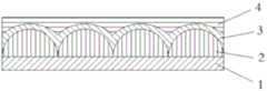
为实现上述目的,本发明采用如下技术方案:一种应用于裸眼3D显示的双胶合微柱透镜光栅器件,其特征在于:包括基板、平凸透镜光栅阵列、凹凸透镜光栅阵列和填充层;所述平凸透镜光栅阵列设置在基板上表面,所述凹凸透镜光栅阵列的凹面与平凸透镜光栅阵列的凸面相互契合;所述填充层的内侧覆盖在凹凸透镜光栅阵列的凸面上,外侧保持平整;所述平凸透镜光栅阵列和凹凸透镜光栅阵列的折射率不同,且填充层的折射率小于平凸透镜光栅阵列与凹凸透镜光栅阵列的复合有效折射率。In order to achieve the above object, the present invention adopts the following technical solution: a double-glued microcylindrical lens grating device applied to naked-eye 3D display, which is characterized in that it includes a substrate, a plano-convex lens grating array, a concave-convex lens grating array, and a filling layer; The plano-convex lens grating array is arranged on the upper surface of the substrate, and the concave surface of the meniscus lens grating array fits with the convex surface of the plano-convex lens grating array; the inner side of the filling layer covers the convex surface of the meniscus lens grating array, and the outer side remains flat; The refractive index of the plano-convex lens grating array and the concave-convex lens grating array are different, and the refractive index of the filling layer is smaller than the composite effective refractive index of the plano-convex lens grating array and the concave-convex lens grating array.
进一步的,所述平凸透镜光栅阵列为汇聚性质的正透镜。Further, the plano-convex lens grating array is a converging positive lens.
进一步的,所述凹凸透镜光栅阵列为发散性质的负透镜。Further, the meniscus lens grating array is a divergent negative lens.
进一步的,所述平凸透镜光栅阵列、凹凸透镜光栅阵列和填充层的材料为紫外线固化液态胶。Further, the material of the plano-convex lens grating array, the concave-convex lens grating array and the filling layer is ultraviolet curable liquid glue.
进一步的,所述紫外线固化液态胶包括有机硅橡胶、丙烯酸型树脂、不饱和聚酯、聚氨酯、环氧树脂。Further, the ultraviolet curable liquid glue includes silicone rubber, acrylic resin, unsaturated polyester, polyurethane, and epoxy resin.
一种裸眼3D显示的双胶合微柱透镜光栅器件的制备方法,其特征在于,包括以下步骤:A method for preparing a double-glued microcylindrical lens grating device for naked-eye 3D display, characterized in that it comprises the following steps:
步骤S1:在基板上涂覆第一层透明的紫外线固化液态胶,使用第一模具通过纳米压印技术将该紫外线固化液态胶刻蚀为平凸透镜光栅阵列并进行固化处理;Step S1: Coating the first layer of transparent UV-curable liquid adhesive on the substrate, using the first mold to etch the UV-curable liquid adhesive into a plano-convex lens grating array and performing curing treatment;
步骤S2:在所述平凸透镜光栅阵列上涂覆第二层透明的紫外线固化液态胶,使用第二模具通过纳米压印技术将该紫外线固化液态胶刻蚀为凹凸透镜光栅阵列并进行固化处理;Step S2: Coating a second layer of transparent UV-curable liquid glue on the plano-convex lens grating array, using a second mold to etch the UV-curable liquid glue into a concave-convex lens grating array and performing curing treatment;
步骤S3:在所述凹凸透镜光栅阵列上涂覆第三层透明的紫外线固化液态胶,使用第三模具通过纳米压印技术将该紫外线固化液态胶刻蚀为填充层并进行固化处理。Step S3: Coating a third layer of transparent UV-curable liquid glue on the concave-convex lens grating array, using the third mold to etch the UV-curable liquid glue into a filling layer by nanoimprint technology and performing curing treatment.
进一步的,所述固化处理为采用冷紫外光设备进行照射处理。Further, the curing treatment is irradiation treatment using cold ultraviolet light equipment.
进一步的,所述第一模具的压印面为与平凸透镜光栅阵列的凸面相契合的凹面。Further, the embossing surface of the first mold is a concave surface matching the convex surface of the plano-convex lens grating array.
进一步的,所述第二模具的压印面为与凹凸透镜光栅阵列的凸面相契合的凹面。Further, the embossing surface of the second mold is a concave surface matching the convex surface of the meniscus lens grating array.
进一步的,所述第三模具的压印面为平面。Further, the embossing surface of the third mold is plane.
本发明与现有技术相比具有以下有益效果:一方面,本发明采用的平凸透镜光栅阵列的折射率n1与凹凸透镜光栅阵列的折射率n2不同,曲率半径不同,能校正球差色差,形成较小的红绿蓝弥散斑,有效提高柱透镜在横向和轴向的分辨率;另一方面,本发明的平凸透镜光栅阵列和凹凸透镜光栅阵列的复合有效折射率大于填充层的折射率n3,形成了双胶合微柱透镜光栅器件的完整结构;最后,光栅的最外层透明薄膜填充材料,能有效防止双胶合微柱透镜光栅器件损坏。本发明同时制备标准模具、薄膜压制工艺,能生产大面积的双胶合微柱透镜光栅器件,能够节约生产成本,扩大产量;与现有普通微柱透镜光栅技术相比,本发明克服了普通微柱透镜光栅的固有缺陷、其平整度提高、生产效率集成、使用寿命长、光聚焦属性显著增强,3D显示综合效果提升。Compared with the prior art, the present invention has the following beneficial effects: on the one hand, the refractive index n1 of the plano-convex lens grating array used in the present invention is different from the refractive index n2 of the concave-convex lens grating array, and the radius of curvature is different, which can correct spherical aberration and chromatic aberration, forming Small red, green and blue diffuse spots can effectively improve the lateral and axial resolution of the cylindrical lens; on the other hand, the composite effective refractive index of the plano-convex lens grating array and the concave-convex lens grating array of the present invention is greater than the refractive index n3 of the filling layer , forming a complete structure of the double-glued micro-pillar lens grating device; finally, the outermost transparent film filling material of the grating can effectively prevent the damage of the double-glued micro-pillar lens grating device. The present invention prepares standard molds and film pressing processes at the same time, can produce large-area double-glued micro-pillar lens grating devices, can save production costs, and expand production; compared with the existing common micro-pillar lens grating technology, the present invention overcomes the common The inherent defects of the cylindrical lens grating, its flatness is improved, the production efficiency is integrated, the service life is long, the light focusing property is significantly enhanced, and the comprehensive effect of 3D display is improved.
附图说明Description of drawings
图1是本发明一实施例的结构示意图。Fig. 1 is a schematic structural diagram of an embodiment of the present invention.
图2是本发明凹凸透镜光栅阵列的局部尺寸示意图。Fig. 2 is a schematic diagram of partial dimensions of the meniscus lens grating array of the present invention.
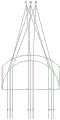
图3是普通光栅的光线调制示意图。Fig. 3 is a schematic diagram of light modulation of a common grating.
图4是本发明的光线调制示意图。Fig. 4 is a schematic diagram of light modulation in the present invention.
图5是本发明的制备流程示意图。Fig. 5 is a schematic diagram of the preparation process of the present invention.
图中:1-基板;2-平凸透镜光栅阵列;3-凹凸透镜光栅阵列;4-填充层;5-第一模具;6-第二模具;7-第三模具。In the figure: 1 - substrate; 2 - plano-convex lens grating array; 3 - concave-convex lens grating array; 4 - filling layer; 5 - first mold; 6 - second mold; 7 - third mold.
具体实施方式Detailed ways
下面结合附图及实施例对本发明做进一步说明。The present invention will be further described below in conjunction with the accompanying drawings and embodiments.
请参照图1,本发明提供一种裸眼3D显示的双胶合微柱透镜光栅器件,其特征在于:包括基板1、平凸透镜光栅阵列2、凹凸透镜光栅阵列3和填充层4;所述平凸透镜光栅阵列设置在基板上表面,所述凹凸透镜光栅阵列的凹面与平凸透镜光栅阵列的凸面相互契合;所述填充层的内侧覆盖在凹凸透镜光栅阵列的凸面上,外侧保持平整;所述平凸透镜光栅阵列的折射率n1和凹凸透镜光栅阵列的折射率n2不同,且n1<n2;且填充层的折射率n3小于平凸透镜光栅阵列与凹凸透镜光栅阵列的复合有效折射率,保证了光栅的效果。Please refer to Fig. 1, the present invention provides a double-glued microcylindrical lens grating device for naked-eye 3D display, which is characterized in that: it includes a
于本实施例中,所述平凸透镜光栅阵列为汇聚性质的正透镜;凹凸透镜光栅阵列为发散性质的负透镜。凹凸透镜光栅阵列的局部示意图请参照图2,中部的厚度h1小于边缘的厚度h2。In this embodiment, the plano-convex lens grating array is a converging positive lens; the concave-convex lens grating array is a diverging negative lens. Please refer to FIG. 2 for a partial schematic diagram of the meniscus grating array. The thickness h1 of the middle part is smaller than the thickness h2 of the edge.
于本实施例中,所述平凸透镜光栅阵列、凹凸透镜光栅阵列和填充层的材料为紫外线固化液态胶;包括有机硅橡胶、丙烯酸型树脂、不饱和聚酯、聚氨酯、环氧树脂。优选的,本实施例平凸透镜光栅阵列、凹凸透镜光栅阵列和填充层的材料采用聚甲基丙烯酸甲酯(PMMA)或聚对苯二甲酸乙二醇酯(PET)等透光材料。而基板采用玻璃、聚甲基丙烯酸甲酯(PMMA)或聚对苯二甲酸乙二醇酯(PET)等透光材料。In this embodiment, the material of the plano-convex lens grating array, the meniscus lens grating array and the filling layer is ultraviolet curable liquid glue; including silicone rubber, acrylic resin, unsaturated polyester, polyurethane, and epoxy resin. Preferably, the materials of the plano-convex lens grating array, the meniscus lens grating array and the filling layer in this embodiment are light-transmitting materials such as polymethyl methacrylate (PMMA) or polyethylene terephthalate (PET). The substrate is made of light-transmitting materials such as glass, polymethyl methacrylate (PMMA) or polyethylene terephthalate (PET).
图3为现有技术中普通光栅的光线调制示意图,普通光栅通过平凸透镜的调光,使得红光(R)的离焦(交点距离屏幕的距离)过大;而图4为本发明的光线调制示意图,通过平凸透镜和凹凸透镜的调制,将红光(R)、绿光(G)、蓝色(B)调制为绿光(G)、红光(R)、蓝色(B)的顺序;且实现红绿蓝三光在横向和纵向空间均具有相同焦距以消除光色散。Fig. 3 is a schematic diagram of light modulation of a common grating in the prior art. The light modulation of a common grating through a plano-convex lens makes the red light (R) defocus (the distance from the intersection point to the screen) too large; and Fig. 4 is the light of the present invention Schematic diagram of modulation, through the modulation of plano-convex lens and concave-convex lens, red light (R), green light (G), blue (B) is modulated into green light (G), red light (R), blue (B) order; and realize that the red, green, and blue lights have the same focal length in the horizontal and vertical spaces to eliminate light dispersion.
请参照图5,本实施例还提供一种裸眼3D显示的双胶合微柱透镜光栅器件的制备方法,包括以下步骤:Please refer to FIG. 5. This embodiment also provides a method for preparing a double-glued microcylindrical lens grating device for naked-eye 3D display, including the following steps:
步骤S1:在基板上涂覆第一层透明的紫外线固化液态胶,使用第一模具5通过纳米压印技术将该紫外线固化液态胶刻蚀为平凸透镜光栅阵列并进行固化处理;脱去第一模具,基板上形成一层透明薄膜即平凸透镜光栅阵列;所述第一模具的压印面为与平凸透镜光栅阵列的凸面相契合的凹面。此步骤中,紫外线固化液态胶固化后的折射率与基板材料基本一致。Step S1: Coating the first layer of transparent UV-curable liquid glue on the substrate, using the
步骤S2:在所述平凸透镜光栅阵列上涂覆第二层透明的紫外线固化液态胶,使用第二模具6通过纳米压印技术将该紫外线固化液态胶刻蚀为凹凸透镜光栅阵列并进行固化处理;脱去第二模具,平凸透镜光栅阵列上形成一层透明薄膜即凹凸透镜光栅阵列;所述第二模具的压印面为与凹凸透镜光栅阵列的凸面相契合的凹面。此步骤中,紫外线固化液态胶固化后的折射率与平凸透镜光栅阵列不一致。Step S2: Coating a second layer of transparent UV-curable liquid glue on the plano-convex lens grating array, using the
步骤S3:在所述凹凸透镜光栅阵列上涂覆第三层透明的紫外线固化液态胶,使用第三模具7通过纳米压印技术将该紫外线固化液态胶刻蚀为填充层并进行固化处理;脱去第三模具,凹凸透镜光栅阵列上形成一层透明薄膜及填充层。填充层填平了凹凸透镜光栅阵列的凸面。所述第三模具的压印面为平面。Step S3: Coating a third layer of transparent UV-curable liquid glue on the concave-convex lens grating array, using the
于本实施例中,所述固化处理为采用冷紫外光设备进行照射处理。In this embodiment, the curing treatment is irradiation treatment using cold ultraviolet light equipment.
以上所述仅为本发明的较佳实施例,凡依本发明申请专利范围所做的均等变化与修饰,皆应属本发明的涵盖范围。The above descriptions are only preferred embodiments of the present invention, and all equivalent changes and modifications made according to the scope of the patent application of the present invention shall fall within the scope of the present invention.
Claims (1)
Priority Applications (1)
| Application Number | Priority Date | Filing Date | Title |
|---|---|---|---|
| CN201710098501.1ACN106646902B (en) | 2017-02-23 | 2017-02-23 | Naked eye 3D display double-glued micro-cylindrical lens grating device and preparation method thereof |
Applications Claiming Priority (1)
| Application Number | Priority Date | Filing Date | Title |
|---|---|---|---|
| CN201710098501.1ACN106646902B (en) | 2017-02-23 | 2017-02-23 | Naked eye 3D display double-glued micro-cylindrical lens grating device and preparation method thereof |
Publications (2)
| Publication Number | Publication Date |
|---|---|
| CN106646902A CN106646902A (en) | 2017-05-10 |
| CN106646902Btrue CN106646902B (en) | 2023-05-19 |
Family
ID=58845681
Family Applications (1)
| Application Number | Title | Priority Date | Filing Date |
|---|---|---|---|
| CN201710098501.1AExpired - Fee RelatedCN106646902B (en) | 2017-02-23 | 2017-02-23 | Naked eye 3D display double-glued micro-cylindrical lens grating device and preparation method thereof |
Country Status (1)
| Country | Link |
|---|---|
| CN (1) | CN106646902B (en) |
Families Citing this family (3)
| Publication number | Priority date | Publication date | Assignee | Title |
|---|---|---|---|---|
| CN108061974A (en)* | 2017-12-12 | 2018-05-22 | 深圳超多维科技有限公司 | Lenticulation device, 3 d display device, the production method of lenticulation device |
| CN108956467B (en)* | 2018-08-09 | 2022-04-22 | 京东方科技集团股份有限公司 | A microfluidic chip and its working method |
| FR3093569B1 (en)* | 2019-03-04 | 2021-03-12 | Alioscopy | PROCESS FOR MANUFACTURING AN AUTOSTEREOSCOPIC SCREEN AND PROCESS FOR TRANSFORMATION OF A DISPLAY SCREEN OF A TWO-DIMENSIONAL IMAGE INTO AN AUTOSTEREOSCOPIC IMAGE DISPLAY SCREEN |
Citations (5)
| Publication number | Priority date | Publication date | Assignee | Title |
|---|---|---|---|---|
| JPH10319878A (en)* | 1997-05-21 | 1998-12-04 | Toshiba Corp | Liquid crystal display |
| JP2000305041A (en)* | 1999-04-26 | 2000-11-02 | Hit Design:Kk | Convex lens array display with picture and its manufacture |
| CN101349770A (en)* | 2008-09-02 | 2009-01-21 | 北京超多维科技有限公司 | Lens components and stereo display device including the same |
| CN202443141U (en)* | 2012-02-23 | 2012-09-19 | 京东方科技集团股份有限公司 | Color filter substrate and 3D display device |
| CN206573791U (en)* | 2017-02-23 | 2017-10-20 | 集美大学 | Double glued microtrabeculae lenticulation devices that a kind of bore hole 3D is shown |
Family Cites Families (2)
| Publication number | Priority date | Publication date | Assignee | Title |
|---|---|---|---|---|
| JP4283339B2 (en)* | 2007-05-18 | 2009-06-24 | パナソニック株式会社 | Stereoscopic image display device |
| CN101464623B (en)* | 2008-12-17 | 2011-01-26 | 顾金昌 | A synthesis method of grating and photosensitive material for digital three-dimensional printing |
- 2017
- 2017-02-23CNCN201710098501.1Apatent/CN106646902B/ennot_activeExpired - Fee Related
Patent Citations (5)
| Publication number | Priority date | Publication date | Assignee | Title |
|---|---|---|---|---|
| JPH10319878A (en)* | 1997-05-21 | 1998-12-04 | Toshiba Corp | Liquid crystal display |
| JP2000305041A (en)* | 1999-04-26 | 2000-11-02 | Hit Design:Kk | Convex lens array display with picture and its manufacture |
| CN101349770A (en)* | 2008-09-02 | 2009-01-21 | 北京超多维科技有限公司 | Lens components and stereo display device including the same |
| CN202443141U (en)* | 2012-02-23 | 2012-09-19 | 京东方科技集团股份有限公司 | Color filter substrate and 3D display device |
| CN206573791U (en)* | 2017-02-23 | 2017-10-20 | 集美大学 | Double glued microtrabeculae lenticulation devices that a kind of bore hole 3D is shown |
Also Published As
| Publication number | Publication date |
|---|---|
| CN106646902A (en) | 2017-05-10 |
Similar Documents
| Publication | Publication Date | Title |
|---|---|---|
| TWI723438B (en) | Gap fill of imprinted structure with spin coated high refractive index material for optical components | |
| CN206573791U (en) | Double glued microtrabeculae lenticulation devices that a kind of bore hole 3D is shown | |
| US8994885B2 (en) | Pre-edging lens and method for manufacturing edged lens | |
| KR102460599B1 (en) | Thermoplastic Optics | |
| JP2024023395A (en) | Methods of manufacturing optical devices and resulting optical devices | |
| CN106646902B (en) | Naked eye 3D display double-glued micro-cylindrical lens grating device and preparation method thereof | |
| CN102565888A (en) | Lens sheet for microlens and lenticular lens | |
| CN108445558B (en) | Optical film structure, method for forming the same, and display device | |
| TW201335624A (en) | Cylindrical lens type stereoscopic display device and method of manufacturing same | |
| CN105093470B (en) | Suspension lens system and wafer-level method for manufacturing suspension lens system | |
| US20160299263A1 (en) | Microlens array, manufacturing method thereof, image acquisition device, and display device | |
| CN111599835B (en) | A display panel and its manufacturing method | |
| KR20130138127A (en) | Manufacturing method of apodizer and optical module | |
| JP2008213210A (en) | Transfer method and optical element manufactured thereby | |
| CN110716248A (en) | Processing technology of multi-column multi-row equivalent negative refractive index flat lens | |
| JP2005250469A (en) | Lens, transmissive screen, and lens manufacturing method | |
| TW201346398A (en) | Light guide plate and method of manufacturing the same | |
| CN106019615B (en) | A display method for switching between 2D/3D | |
| KR101363473B1 (en) | Polymer lens with anti-reflective structures and making method of the same | |
| JP2009098641A (en) | Liquid crystal fresnel lens, fresnel lens mold, and method for producing the mold | |
| JP2017211466A (en) | Diffractive optical element | |
| CN106950627B (en) | Naked eye 3D imaging grating and preparation method thereof | |
| CN204439945U (en) | A kind of bore hole 3D diaphragm and comprise the 3D stereogram of this diaphragm | |
| KR20150080289A (en) | Mold for optical film, method of fabricating the same and method of fabricating optical film using Mold for optical film | |
| CN104133261A (en) | Grating and preparation method thereof |
Legal Events
| Date | Code | Title | Description |
|---|---|---|---|
| PB01 | Publication | ||
| PB01 | Publication | ||
| SE01 | Entry into force of request for substantive examination | ||
| SE01 | Entry into force of request for substantive examination | ||
| GR01 | Patent grant | ||
| GR01 | Patent grant | ||
| CF01 | Termination of patent right due to non-payment of annual fee | ||
| CF01 | Termination of patent right due to non-payment of annual fee | Granted publication date:20230519 |