CN106573128B - Delivery assistance device for catheter - Google Patents
Delivery assistance device for catheterDownload PDFInfo
- Publication number
- CN106573128B CN106573128BCN201580042883.5ACN201580042883ACN106573128BCN 106573128 BCN106573128 BCN 106573128BCN 201580042883 ACN201580042883 ACN 201580042883ACN 106573128 BCN106573128 BCN 106573128B
- Authority
- CN
- China
- Prior art keywords
- distal section
- flexible distal
- proximal shaft
- flexibility
- flexible
- Prior art date
- Legal status (The legal status is an assumption and is not a legal conclusion. Google has not performed a legal analysis and makes no representation as to the accuracy of the status listed.)
- Active
Links
Images


Classifications
- A—HUMAN NECESSITIES
- A61—MEDICAL OR VETERINARY SCIENCE; HYGIENE
- A61M—DEVICES FOR INTRODUCING MEDIA INTO, OR ONTO, THE BODY; DEVICES FOR TRANSDUCING BODY MEDIA OR FOR TAKING MEDIA FROM THE BODY; DEVICES FOR PRODUCING OR ENDING SLEEP OR STUPOR
- A61M25/00—Catheters; Hollow probes
- A61M25/0043—Catheters; Hollow probes characterised by structural features
- A61M25/0054—Catheters; Hollow probes characterised by structural features with regions for increasing flexibility
- A—HUMAN NECESSITIES
- A61—MEDICAL OR VETERINARY SCIENCE; HYGIENE
- A61M—DEVICES FOR INTRODUCING MEDIA INTO, OR ONTO, THE BODY; DEVICES FOR TRANSDUCING BODY MEDIA OR FOR TAKING MEDIA FROM THE BODY; DEVICES FOR PRODUCING OR ENDING SLEEP OR STUPOR
- A61M25/00—Catheters; Hollow probes
- A61M25/01—Introducing, guiding, advancing, emplacing or holding catheters
- A61M25/0172—Exchanging a guidewire while keeping the catheter in place
- A—HUMAN NECESSITIES
- A61—MEDICAL OR VETERINARY SCIENCE; HYGIENE
- A61M—DEVICES FOR INTRODUCING MEDIA INTO, OR ONTO, THE BODY; DEVICES FOR TRANSDUCING BODY MEDIA OR FOR TAKING MEDIA FROM THE BODY; DEVICES FOR PRODUCING OR ENDING SLEEP OR STUPOR
- A61M25/00—Catheters; Hollow probes
- A61M25/0067—Catheters; Hollow probes characterised by the distal end, e.g. tips
- A61M25/008—Strength or flexibility characteristics of the catheter tip
- A—HUMAN NECESSITIES
- A61—MEDICAL OR VETERINARY SCIENCE; HYGIENE
- A61M—DEVICES FOR INTRODUCING MEDIA INTO, OR ONTO, THE BODY; DEVICES FOR TRANSDUCING BODY MEDIA OR FOR TAKING MEDIA FROM THE BODY; DEVICES FOR PRODUCING OR ENDING SLEEP OR STUPOR
- A61M25/00—Catheters; Hollow probes
- A61M25/01—Introducing, guiding, advancing, emplacing or holding catheters
- A61M25/0102—Insertion or introduction using an inner stiffening member, e.g. stylet or push-rod
- A—HUMAN NECESSITIES
- A61—MEDICAL OR VETERINARY SCIENCE; HYGIENE
- A61M—DEVICES FOR INTRODUCING MEDIA INTO, OR ONTO, THE BODY; DEVICES FOR TRANSDUCING BODY MEDIA OR FOR TAKING MEDIA FROM THE BODY; DEVICES FOR PRODUCING OR ENDING SLEEP OR STUPOR
- A61M25/00—Catheters; Hollow probes
- A61M25/01—Introducing, guiding, advancing, emplacing or holding catheters
- A61M25/0105—Steering means as part of the catheter or advancing means; Markers for positioning
- A61M25/0133—Tip steering devices
- A61M25/0141—Tip steering devices having flexible regions as a result of using materials with different mechanical properties
- A—HUMAN NECESSITIES
- A61—MEDICAL OR VETERINARY SCIENCE; HYGIENE
- A61M—DEVICES FOR INTRODUCING MEDIA INTO, OR ONTO, THE BODY; DEVICES FOR TRANSDUCING BODY MEDIA OR FOR TAKING MEDIA FROM THE BODY; DEVICES FOR PRODUCING OR ENDING SLEEP OR STUPOR
- A61M25/00—Catheters; Hollow probes
- A61M25/01—Introducing, guiding, advancing, emplacing or holding catheters
- A61M25/06—Body-piercing guide needles or the like
- A61M25/0662—Guide tubes
- A—HUMAN NECESSITIES
- A61—MEDICAL OR VETERINARY SCIENCE; HYGIENE
- A61M—DEVICES FOR INTRODUCING MEDIA INTO, OR ONTO, THE BODY; DEVICES FOR TRANSDUCING BODY MEDIA OR FOR TAKING MEDIA FROM THE BODY; DEVICES FOR PRODUCING OR ENDING SLEEP OR STUPOR
- A61M25/00—Catheters; Hollow probes
- A61M25/01—Introducing, guiding, advancing, emplacing or holding catheters
- A61M25/0105—Steering means as part of the catheter or advancing means; Markers for positioning
- A61M25/0133—Tip steering devices
- A61M2025/0161—Tip steering devices wherein the distal tips have two or more deflection regions
- A—HUMAN NECESSITIES
- A61—MEDICAL OR VETERINARY SCIENCE; HYGIENE
- A61M—DEVICES FOR INTRODUCING MEDIA INTO, OR ONTO, THE BODY; DEVICES FOR TRANSDUCING BODY MEDIA OR FOR TAKING MEDIA FROM THE BODY; DEVICES FOR PRODUCING OR ENDING SLEEP OR STUPOR
- A61M25/00—Catheters; Hollow probes
- A61M25/01—Introducing, guiding, advancing, emplacing or holding catheters
- A61M2025/0175—Introducing, guiding, advancing, emplacing or holding catheters having telescopic features, interengaging nestable members movable in relations to one another
- A—HUMAN NECESSITIES
- A61—MEDICAL OR VETERINARY SCIENCE; HYGIENE
- A61M—DEVICES FOR INTRODUCING MEDIA INTO, OR ONTO, THE BODY; DEVICES FOR TRANSDUCING BODY MEDIA OR FOR TAKING MEDIA FROM THE BODY; DEVICES FOR PRODUCING OR ENDING SLEEP OR STUPOR
- A61M2205/00—General characteristics of the apparatus
- A61M2205/02—General characteristics of the apparatus characterised by a particular materials
- A—HUMAN NECESSITIES
- A61—MEDICAL OR VETERINARY SCIENCE; HYGIENE
- A61M—DEVICES FOR INTRODUCING MEDIA INTO, OR ONTO, THE BODY; DEVICES FOR TRANSDUCING BODY MEDIA OR FOR TAKING MEDIA FROM THE BODY; DEVICES FOR PRODUCING OR ENDING SLEEP OR STUPOR
- A61M2207/00—Methods of manufacture, assembly or production
- A—HUMAN NECESSITIES
- A61—MEDICAL OR VETERINARY SCIENCE; HYGIENE
- A61M—DEVICES FOR INTRODUCING MEDIA INTO, OR ONTO, THE BODY; DEVICES FOR TRANSDUCING BODY MEDIA OR FOR TAKING MEDIA FROM THE BODY; DEVICES FOR PRODUCING OR ENDING SLEEP OR STUPOR
- A61M2210/00—Anatomical parts of the body
- A61M2210/08—Limbs
- A61M2210/083—Arms
- A—HUMAN NECESSITIES
- A61—MEDICAL OR VETERINARY SCIENCE; HYGIENE
- A61M—DEVICES FOR INTRODUCING MEDIA INTO, OR ONTO, THE BODY; DEVICES FOR TRANSDUCING BODY MEDIA OR FOR TAKING MEDIA FROM THE BODY; DEVICES FOR PRODUCING OR ENDING SLEEP OR STUPOR
- A61M2210/00—Anatomical parts of the body
- A61M2210/12—Blood circulatory system
- A—HUMAN NECESSITIES
- A61—MEDICAL OR VETERINARY SCIENCE; HYGIENE
- A61M—DEVICES FOR INTRODUCING MEDIA INTO, OR ONTO, THE BODY; DEVICES FOR TRANSDUCING BODY MEDIA OR FOR TAKING MEDIA FROM THE BODY; DEVICES FOR PRODUCING OR ENDING SLEEP OR STUPOR
- A61M25/00—Catheters; Hollow probes
- A61M25/0009—Making of catheters or other medical or surgical tubes
Landscapes
- Health & Medical Sciences (AREA)
- Life Sciences & Earth Sciences (AREA)
- Biophysics (AREA)
- Pulmonology (AREA)
- Engineering & Computer Science (AREA)
- Anesthesiology (AREA)
- Biomedical Technology (AREA)
- Heart & Thoracic Surgery (AREA)
- Hematology (AREA)
- Animal Behavior & Ethology (AREA)
- General Health & Medical Sciences (AREA)
- Public Health (AREA)
- Veterinary Medicine (AREA)
- Media Introduction/Drainage Providing Device (AREA)
- Materials For Medical Uses (AREA)
Abstract
Description
Translated fromChinese相关申请的交叉引用CROSS-REFERENCE TO RELATED APPLICATIONS
本申请依据35 U.S.C.§119要求2014年6月9日提交的美国临时申请No.62/009,727的优先权,该文献的全部内容通过引用并入本文。This application claims priority under 35 U.S.C. § 119 to US Provisional Application No. 62/009,727, filed June 9, 2014, the entire contents of which are incorporated herein by reference.
技术领域technical field
本发明关于医疗设备以及制造医疗设备的方法。更具体地说,本发明关于具有连接其他结构的管状设备的细长体内医疗装置,以及制造与使用这种装置的方法。The present invention relates to medical devices and methods of making medical devices. More particularly, the present invention relates to elongated in vivo medical devices having tubular devices attached to other structures, and methods of making and using such devices.
背景技术Background technique
用于医疗的各种各样体内医疗装置已被开发,例如在血管使用。这种装置中的一部份包括导丝,导管等。通过多种不同制造方法制造这种装置,并且可根据多种方法的任一使用这种装置。现有的医疗装置和方法,都存在某些优点和缺点。持续存在提供替代医疗装置,以及制造与使用医疗装置的替代方法的需求。A wide variety of in vivo medical devices have been developed for medical use, such as in blood vessels. Some of these devices include guide wires, catheters, and the like. Such devices are manufactured by a number of different manufacturing methods, and may be used according to any of a number of methods. Existing medical devices and methods have certain advantages and disadvantages. There is a continuing need to provide alternative medical devices, as well as alternative methods of making and using medical devices.
发明内容SUMMARY OF THE INVENTION
本揭示提供医疗设备的设计、材料、制造方法、以及用途的替代品,此类医疗设备诸如输送辅助装置与指引导管组件。公开了一种与指引导管组合使用的输送辅助装置,输送辅助装置包含:The present disclosure provides alternatives to the design, materials, methods of manufacture, and uses of medical devices, such as delivery aids and guide catheter assemblies. Disclosed is a delivery aid used in combination with a guiding catheter, the delivery aid comprising:
细长近侧轴;slender proximal shaft;
从细长近侧轴往远侧延伸的柔性远侧段,柔性远侧段至少包括具有第一柔性的第一部与具有第二柔性的第二部;a flexible distal segment extending distally from the elongated proximal shaft, the flexible distal segment comprising at least a first portion having a first flexibility and a second portion having a second flexibility;
延伸穿过柔性远侧段的腔体,腔体构造成容纳可延伸穿过腔体的导丝;以及a lumen extending through the flexible distal segment, the lumen being configured to receive a guidewire extendable through the lumen; and
由柔性远侧段往远侧延伸的锥形末梢。A tapered tip extending distally from a flexible distal segment.
作为上述任何实施例的替代或补充,聚合材料的第一部具有第一硬度,而相同聚合材料的第二部具有不同于第一硬度的第二硬度。Alternatively or in addition to any of the above embodiments, a first portion of polymeric material has a first hardness and a second portion of the same polymeric material has a second hardness different from the first hardness.
作为上述任何实施例的替代或补充,第一部由第一聚合材料构成,而第二部由第二聚合材料构成,第一聚合材料与第二聚合材料不同。Alternatively or in addition to any of the above embodiments, the first portion is comprised of a first polymeric material and the second portion is comprised of a second polymeric material, the first polymeric material being different from the second polymeric material.
作为上述任何实施例的替代或补充,柔性远侧段进一步包括具有第三柔性的第三部。Alternatively or in addition to any of the above embodiments, the flexible distal segment further includes a third portion having a third flexibility.
作为上述任何实施例的替代或补充,第三部由相同聚合材料制成,但具有不同于第一与第二硬度的第三硬度。Alternatively or in addition to any of the above embodiments, the third portion is made of the same polymeric material, but has a third hardness that is different from the first and second hardnesses.
作为上述任何实施例的替代或补充,第三部由第三聚合材料构成,第三聚合材料与第二聚合材料不同。Alternatively or in addition to any of the above embodiments, the third portion is comprised of a third polymeric material, the third polymeric material being different from the second polymeric material.
作为上述任何实施例的替代或补充,柔性远侧段在第一部与第二部之间提供柔性的逐步变化。Alternatively or in addition to any of the above embodiments, the flexible distal segment provides a gradual change in flexibility between the first portion and the second portion.
作为上述任何实施例的替代或补充,柔性远侧段包括从细长近侧轴延伸的管状结构。Alternatively or in addition to any of the above embodiments, the flexible distal segment includes a tubular structure extending from the elongated proximal shaft.
作为上述任何实施例的替代或补充,柔性远侧段包括一并形成细长近侧轴与柔性远侧段两者的管状结构加宽部。Alternatively or in addition to any of the above embodiments, the flexible distal segment includes a tubular structural widening that together forms both the elongated proximal shaft and the flexible distal segment.
作为上述任何实施例的替代或补充,末梢具有末梢柔性,末梢柔性与第一或第二柔性不同。Alternatively or in addition to any of the above embodiments, the tip has a tip flexibility that is different from the first or second flexibility.
公开一种组件。组件包括:Expose a component. Components include:
在远侧区与近侧区之间延伸的指引导管;a guiding catheter extending between the distal region and the proximal region;
由远侧区延伸到近侧区的指引导管腔体;以及a guide catheter lumen extending from the distal region to the proximal region; and
可设置于指引导管腔体之内的输送辅助装置,输送辅助装置包括:A delivery aid that can be arranged in the guide catheter cavity, the delivery aid includes:
细长近侧轴;slender proximal shaft;
从细长近侧轴往远侧延伸的柔性远侧段,柔性远侧段至少包括具有第一柔性的第一部与具有第二柔性的第二部;a flexible distal segment extending distally from the elongated proximal shaft, the flexible distal segment comprising at least a first portion having a first flexibility and a second portion having a second flexibility;
延伸穿过柔性远侧段的腔体;以及extending through the lumen of the flexible distal segment; and
由柔性远侧段往远侧延伸的锥形末梢。A tapered tip extending distally from a flexible distal segment.
作为上述任何实施例的替代或补充,输送辅助装置构造成设置于指引导管之中以推进组件,一旦组件到达脉管系统中的期望位置,即从指引导管腔体上将输送辅助装置拆除。Alternatively or in addition to any of the above embodiments, the delivery aid is configured to be disposed within the guide catheter to advance the assembly and to remove the delivery aid from the guide catheter lumen once the assembly reaches the desired location in the vasculature.
作为上述任何实施例的替代或补充,当输送辅助装置设置于指引导管腔体之中以推进组件时,使指向导管变硬。As an alternative to or in addition to any of the above embodiments, the guide catheter is stiffened when the delivery aid is positioned within the guide catheter lumen to advance the assembly.
作为上述任何实施例的替代或补充,柔性远侧段包含从细长近侧轴延伸的管状结构。Alternatively or in addition to any of the above embodiments, the flexible distal segment includes a tubular structure extending from the elongated proximal shaft.
作为上述任何实施例的替代或补充,柔性远侧段包含一并形成细长近侧轴与柔性远侧段两者的管状结构加宽部。Alternatively or in addition to any of the above embodiments, the flexible distal segment includes a tubular structural widening that together form both the elongated proximal shaft and the flexible distal segment.
作为上述任何实施例的替代或补充,柔性远侧段进一步包含具有第三柔性的第三部。Alternatively or in addition to any of the above embodiments, the flexible distal segment further includes a third portion having a third flexibility.
公开一种到达患者的心脏脉管系统的方法。方法包括:A method of reaching the cardiac vasculature of a patient is disclosed. Methods include:
获得进入患者手腕中动脉的通路;gain access to the patient's middle wrist artery;
通过动脉推进导丝到达所述心脏脉管系统内的期望位置;advancing a guidewire through an artery to a desired location within the cardiac vasculature;
提供与指引导管组合的输送辅助装置;provide delivery aids in combination with guide catheters;
将输送辅助装置与指引导管结合,并推进导丝到心脏脉管系统内的期望位置;以及combining the delivery aid with the guide catheter and advancing the guidewire to the desired location within the cardiac vasculature; and
取出输送辅助装置,使得后续装置可以通过指引导管输送。The delivery aid is removed so that subsequent devices can be delivered through the guide catheter.
作为上述任何实施例的替代或补充,提供与指引导管组合的输送辅助装置包括提供具有细长近侧轴与远侧轴段的输送辅助装置,远侧轴段包括具有第一柔性的第一部和具有第二柔性的第二部,以及从远侧轴段向远侧延伸的锥形末梢。As an alternative to or in addition to any of the above embodiments, providing a delivery aid in combination with a guide catheter includes providing a delivery aid having an elongated proximal shaft and a distal shaft segment including a first portion having a first flexibility and a second portion having a second flexibility, and a tapered tip extending distally from the distal shaft segment.
作为上述任何实施例的替代或补充,获得进入患者手腕中动脉的通路包括获得进入桡动脉的通路。Alternatively or in addition to any of the above embodiments, obtaining access to the patient's middle wrist artery includes obtaining access to the radial artery.
作为上述任何实施例的替代或补充,通过动脉推进导丝到达所述心脏脉管系统内的期望位置包括透过导丝推进指引导管与输送辅助装置的组合,而不使用指引鞘。Alternatively or in addition to any of the above embodiments, advancing a guidewire through an artery to a desired location within the cardiac vasculature includes advancing a combination of an indexing catheter and delivery aid through the guidewire without using an indexing sheath.
上述一些实施例的发明内容的意图不在描述每个实施例或本揭示的每种实施方式。以下的附图与具体实施方法,将更详尽地陈述这些实施例。The above summary of some of the embodiments is not intended to describe each embodiment or every implementation of the present disclosure. The following figures and specific implementation methods will describe these embodiments in more detail.
附图说明Description of drawings
本发明的详细描述,具体参考附图在下文中作出说明。A detailed description of the present invention is hereinafter set forth with particular reference to the accompanying drawings.
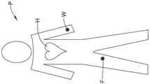
图1是患者的示意图。Figure 1 is a schematic diagram of a patient.
图2是图1中患者的手腕的示意图。FIG. 2 is a schematic illustration of the wrist of the patient of FIG. 1 .
图3是心脏脉管系统的局部示意图,显示插入心脏动脉中的导丝。Figure 3 is a partial schematic view of the cardiac vasculature showing a guidewire inserted into a cardiac artery.
图4是心脏脉管系统的局部示意图,显示包括输送辅助装置和指引导管的组件,指引导管在图3中导丝上延伸。4 is a partial schematic view of the cardiac vasculature showing an assembly including a delivery aid and an indexing catheter extending over the guidewire of FIG. 3 .
图5是心脏脉管系统的局部示意图,显示当输送辅助装置被移除,指引导管在图3中导丝上延伸。5 is a partial schematic view of the cardiac vasculature showing the guide catheter extending over the guide wire of FIG. 3 when the delivery assist device is removed.
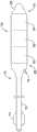
图6是适用于图4中组件的输送辅助装置的侧视图。FIG. 6 is a side view of a delivery aid suitable for use with the assembly of FIG. 4 .
图7是适用于图4中组件的输送辅助装置的侧视图。FIG. 7 is a side view of a delivery aid suitable for use with the assembly of FIG. 4 .
图8是图4中组件的侧视图。FIG. 8 is a side view of the assembly of FIG. 4 .
图9是图8中组件的局部剖视图。FIG. 9 is a partial cross-sectional view of the assembly of FIG. 8 .
虽然本公开内容适于各种修改和替代形式,但是其细节已经通过附图中的示例示出并将被详细描述。然而,应当理解,不是意图限制本发明在所描述的特定实施例中。相反地,是希望保护所有落入本公开的精神和范围内的修改、等同物和替代物。While the present disclosure is amenable to various modifications and alternative forms, the details thereof have been shown by way of example in the accompanying drawings and will be described in detail. It should be understood, however, that the intention is not to limit the invention to the particular embodiments described. On the contrary, the intention is to protect all modifications, equivalents, and alternatives falling within the spirit and scope of this disclosure.
具体实施方式Detailed ways
对以下所限定术语提供定义,意指为应当适用这些定义,除非上下文另有说明。Definitions are provided for the terms defined below, and are intended to apply unless the context dictates otherwise.
无论是否有明确指出,本文假定所有数值均被术语“约”修饰。术语“约”通常是指本领域技术人员认为等同于所述值(例如,具有相同的函数或结果)的数字范围。在许多情况下,术语“约”可以包括四舍五入到最接近的有效数字的数值。All numerical values are assumed herein to be modified by the term "about" whether or not explicitly stated. The term "about" generally refers to a range of numbers that one of ordinary skill in the art considers equivalent to the stated value (eg, having the same function or result). In many instances, the term "about" can include a numerical value rounded to the nearest significant digit.
由两端数字界定的数值范围表述,包括该范围内所有数字(例如,1至5包括1、1.5、2、2.75、3、3.80、4、和5)。The recitation of numerical ranges delimited by numbers on both ends includes all numbers within that range (eg, 1 to 5 includes 1, 1.5, 2, 2.75, 3, 3.80, 4, and 5).
如本说明书和所附权利要求中所使用的单数形式“一”、“一个”、及“所述”包括复数对象,除非内容中另有明确说明。如本说明书和所附权利要求书中,通常使用的术语“或”,其意义包括“和/或”,除非内容中另有明确说明。As used in this specification and the appended claims, the singular forms "a," "an," and "the" include plural referents unless the content clearly dictates otherwise. As in this specification and the appended claims, the term "or" is generally employed in its sense including "and/or" unless the content clearly dictates otherwise.
本文中引述的“一个实施例”,“某些实施例”,“其他实施例”等,表示包括具体特征、结构或特性的实施例,但并非每个实施例必须包括该具体特征、结构或特性。而且,这些词语不一定要参考相同的实施例。进一步地说,当描述一个具体特征、结构、或特性与一个实施例(或多个实施例)相联系,不应理解该具体特征、结构或特性也可以与别的实施例相联系,无论是否有明确描述,除非有明确证据或相反说明。References herein to "one embodiment," "certain embodiments," "other embodiments," etc., mean an embodiment that includes a particular feature, structure, or characteristic, but not every embodiment necessarily includes that particular feature, structure, or characteristic. characteristic. Moreover, these terms are not necessarily referring to the same embodiment. Furthermore, when a particular feature, structure, or characteristic is described in association with one embodiment (or embodiments), it should not be understood that the particular feature, structure, or characteristic may also be associated with other embodiments, whether or not There is a clear description, unless there is clear evidence or the contrary.
下面的详细描述应参考附图来阅读,其中在不同的附图中相似的元件有相同的编号。所述详细描述和附图,不一定是按比例的,描绘说明性实施例的意图不在限制本发明的范围。The following detailed description should be read with reference to the accompanying drawings, wherein like elements are numbered in the different figures. The detailed description and drawings, which are not necessarily to scale, depict illustrative embodiments and are not intended to limit the scope of the invention.
各种不同的医学干预需要通过微创透皮方法进入心脏脉管系统。图1提供具有心脏H的患者P的示意图。在许多情况下,可以通过经由患者股动脉进入脉管系统而到达心脏H。位置F表示适合进入股动脉的进入点。在一些情况下,可以通过患者手腕中的动脉进入脉管系统到达心脏H。位置W表示适合进入手腕中的动脉的进入点。A variety of different medical interventions require minimally invasive transdermal access to the cardiac vasculature. FIG. 1 provides a schematic illustration of a patient P with a heart H. FIG. In many cases, the heart H can be reached by entering the vasculature via the patient's femoral artery. Position F represents a suitable entry point into the femoral artery. In some cases, the heart H may be reached through arteries in the patient's wrist into the vasculature. Location W represents an entry point suitable for entering the artery in the wrist.
应当理解,两种方法都有优点和缺点。例如,股动脉通道一般提供了较大血管的入口,这意味着有更大空间来导引血管内装置通过脉管系统到达心脏H。然而,基本上因为在相对较大的动脉中制造了相对较大的孔,而存在关于控制术后出血的缺失。It should be understood that both approaches have advantages and disadvantages. For example, the femoral artery access generally provides access to larger blood vessels, which means there is more space to guide the intravascular device through the vasculature to the heart H. However, basically because relatively large holes are made in relatively large arteries, there is a lack of control regarding postoperative bleeding.
相反地,因为基本上在相对较小的动脉中制造了相对较小的孔,通过位置W的通道一般对于术后出血具有较少的潜在问题。然而,因为脉管系统通常较小,用来导引血管内装置通过脉管系统到达心脏H的空间也较小。此外,导引至患者P的肩部区域时会特别困难。Conversely, because relatively small holes are essentially made in relatively small arteries, passage through location W generally has fewer potential problems for postoperative bleeding. However, because the vasculature is generally smaller, the space available to guide the intravascular device through the vasculature to the heart H is also smaller. Furthermore, navigation to the shoulder region of patient P can be particularly difficult.
图2是患者P的腕10与对应的手12的示意图。本图示出腕10的内侧与手12的掌部。腕的脉管系统包括桡动脉14与尺动脉16。应当理解,因为经由浅掌弓18将桡动脉14与尺动脉16流体联接,有冗余的血液可流进手中。而由于数个原因,这是具有优点的。这意味着手术过程中,即使桡动脉14与尺动脉16其中之一被闭锁,血还是可以流进手12内。这也表示手术过程中,即使桡动脉14与尺动脉16其中之一损坏,血仍然可以流进手12内。FIG. 2 is a schematic illustration of patient P's wrist 10 and
可以使用桡动脉14或尺动脉16两者中任一。在许多情况下,会使用桡动脉14。为了简单起见,仅描述使用桡动脉14的状况,请理解可用尺动脉16来取代。可藉由多种技术以进入桡动脉14,包括使用一个以上的增加直径的针、导引鞘等。在一些实施例中,一旦进入并到达桡动脉14的内部,附加的血管内装置,例如导丝,可以不使用导引鞘而延伸通过切入点并进入桡动脉14。此为公知的无鞘法。Either the radial artery 14 or the
图3是患者P的主动脉20局部的极简要示意图。主动脉20的所示部分包括具有孔24的冠状动脉22。应当理解,根据经过的脉管系统决定如何到达主动脉20的内部,意即,是经过股骨或是经过手腕。如图所示,导丝26已被推送通过桡动脉14并且通过脉管系统到达主动脉20。导丝26的末端28已被推送通过孔24并推进到冠状动脉22中的期望位置30。虽然未明确示出,举例来说,期望位置30可对应于部分动脉闭塞或完全动脉闭塞。FIG. 3 is a very simplified schematic diagram of a portion of the
转至图4,组件32已被推送至导丝26上,到达期望位置30。在一些实施例中,组件32包括指引导管34与位于指引导管34内且由指引导管34往远端延伸的输送辅助装置36。输送辅助装置36在定位于指引导管34之中时可被认为能增强指引导管34的硬度且因而增强了其可推动性,这将参考图6至图9做进一步的说明与描述。在一些实施例中,插入输送辅助装置36可以改变指引导管34的形状。举例来说,在一些状况下,插入指引导管34的输送辅助装置36可至少部分强化指引导管34。在一些状况下,输送辅助导管36可能是弯曲的,因此插入指引导管34的输送辅助装置36可导致指引导管34弯曲。Turning to FIG. 4 , the
一旦组件32成功地被引导至脉管系统并到达期望位置30,可移除输送辅助装置36,如图5所示。可以看出指引导管34的末端38保持定位在冠状动脉22内,但是输送辅助装置36已经缩回。一旦已经移除输送辅助装置36,可通过指引导管34推进其它治疗装置到导引线26之上。应注意,虽然本文中指引导管34具有特定的标号,但在一些实施例中,指引导管34可以替换为指引延伸导管。尽管未明确示出,在一些实施例中,指引导管34和输送辅助装置36的组合可用来当作指引延伸导管。Once the
图6与图7提供可用来当作特殊输送辅助装置的组件32的部分示意图。图6描述包括近侧轴42的输送辅助装置40,近侧轴42从近侧毂44往远端延伸至柔性远侧段46。可以看到内腔48延伸通过柔性远侧段46。在一些实施例中,近侧轴42可相对坚硬以改善推进性,同时柔性远侧段46则更具有柔性有助于通过脉管系统内的转弯处。在一些实施例中,柔性远侧段46可以被认为是相对于近侧轴42固定的管状结构。6 and 7 provide partial schematic views of the
在一些实施例中,柔性远侧段46可由单一材料制成并且表现出一致的性质,例如整体长度均具有柔性。在一些实施例中,柔性远侧段46可由不同材料制成,并具有不同的特性,例如柔性。示意性地显示柔性远侧段46被分为第一部50、第二部52、以及第三部54。举例来说,末梢56可被认为是第四部,或与第三部54具有相同性质。尽管示出了三个部,应当理解该柔性远侧段46可以被分成任意数量的部,每一个部具有特定的特性。In some embodiments, the flexible
在一些实施例中,相邻的部分之间可具有明显逐步变化的材料及/或性质。在一些实施例中,相邻的部分之间可具有梯度变化的材料及/或性质。在一些实施例中,举例来说,柔性远侧段46整体的材料及性质可在近端58到远端60之间具有梯度变化。In some embodiments, there may be significant stepwise changes in materials and/or properties between adjacent portions. In some embodiments, adjacent portions may have graded materials and/or properties between adjacent portions. In some embodiments, the material and properties of the entire flexible
在一些实施例中,举例来说,由聚合材料构成的第一部50具有第一硬度,以及由同样聚合材料构成的第二部52但具有相异于第一硬度的第二硬度。如果第三部54存在,可由同样聚合材料构成,但具有相异于第一与第二硬度的第三硬度。任何具有期望硬度的聚合材料都适合使用。在一个示例性但非限制性的实施例中,聚合材料可以是尼龙材料,如聚醚嵌段酰胺(PEBA),举例来说可购买商标为
另外,在一些实施例中,第一聚合材料构成第一部50,第二聚合材料构成第二部52,以及第三聚合材料构成第三部54。可使用多种不同的聚合材料。在一些实施例中,柔性远侧段46可以是单层。在一些实施例中,可以预期的是柔性远侧段46可具有延伸柔性末端46长度的层,以及由多个不同材料的区段组成的第二层,以提供第一部分50、第二部份52、以及第三部份54所需的性质。Additionally, in some embodiments, the first polymeric material constitutes the
图7示出了输送辅助装置70,其包括从近端毂74延伸至柔性远侧段76的近侧轴段72。在一些实施例中,柔性远侧段76并非固定于近侧轴段72的独立分开的元件,而是呈现为一并形成近侧轴段72以及柔性远侧段76的管状结构加宽部。FIG. 7 shows a
腔体78如所见的延伸通过柔性远侧段76。在一些实施例中,近侧轴段72可相对坚硬以改善推进性,同时柔性远侧段76更具有柔性以助于通过脉管系统的转弯处。在一些实施例中,近侧轴段72包括复数个相异区域,其由不同材料制成及/或具有不同特性,例如柔性。The
在一些实施例中,柔性远侧段76可由单一材料制成并且表现出一致的特性,例如在整个长度上均具有柔性。在一些实施例中,柔性远侧段76可由不同材料制成,并具有不同的特性,例如柔性。示意性地显示柔性远侧段76被分成第一部80、第二部82、以及第三部84。举例来说,末梢86可被认为是第四部,或与第三部84具有相同性质。尽管示出这三部时,应该理解柔性远侧段76可被分为任意数量的部,各部具有特定的特性。In some embodiments, the flexible
在一些实施例中,在一些实施例中,相邻的部之间可具有明显逐步变化的材料及/或性质。在一些实施例中,相邻的部之间可具有梯度变化的材料及/或性质。在一些实施例中,举例来说,柔性远侧段76整体的材料及性质可在近端88到末端90之间具有梯度变化。In some embodiments, adjacent sections may have significantly progressively varying materials and/or properties between adjacent sections. In some embodiments, adjacent sections may have graded materials and/or properties between adjacent sections. In some embodiments, the material and properties of the entire flexible
在一些实施例中,举例来说,由聚合材料构成的第一部80具有第一硬度,以及由同样聚合材料构成的第二部82但具有相异于第一硬度的第二硬度。如果第三部84存在,可由同样聚合材料构成,但具有相异于第一与第二硬度的第三硬度。In some embodiments, for example, a
任何具有期望硬度或是期望硬度范围内的聚合材料都适合使用。在一个示例性但非限制性的实施例中,聚合材料可以是尼龙材料,如聚醚嵌段酰胺(PEBA),举例来说可购买商标为
另外,在一些实施例中,第一聚合材料构成第一部80,第二聚合材料构成第二部82,以及第三聚合材料构成第三部84。可使用多种不同的聚合材料。在一些实施例中,柔性远侧段76可以是单层。在一些实施例中,可以预期的是柔性远侧段76可具有延伸柔性远侧段76长度的层,以及多个不同材料的区段组成的第二层,以提供第一部分80、第二部份82、以及第三部份84所需的性质。Additionally, in some embodiments, the first polymeric material constitutes the
图8为组件100的侧视图,而图9为图8中剖面线9-9的剖面图。组件100包含具有近端毂104的指引导管102。应当理解,指引导管102可相当于图4和图5所示的指引导管32。可看到输送辅助装置106的一部分从指引导管102向远侧延伸。特别参考图9,虽然指引导管102和输送辅助装置106,均被示出为单层,但应当理解,在一些实施例中,指引导管102及/或输送辅助装置106可为多层,且以多种不同的材料组成。FIG. 8 is a side view of the
在一些实施例中,导丝26、指引导管32与102、输送辅助装置36、40、70与106其中的一些可包含管状结构或者是由管状结构组成,该管状结构内部形成复数个长槽,以进一步控制前述装置的柔性特性。若长槽存在,可相对于承载狭长孔的管状结构的纵向轴线相同或大致相同的角度设置长槽。可按直角或大致为直角来设置狭长孔,及/或设置在正交于管状结构纵向轴线的平面上。然而,在其他实施例中,长槽可设置为非直角,及/或设置于不正交于管状结构的纵向轴线的平面上。另外,一组一个以上的长槽可相对于另一组一个以上的长槽以不同的角度设置。在应用的范围内,长槽的配置及/或结构还可以包括在美国专利公开号US2004/0181174中公开的任何一种。该文献的全部内容通过引用并入本文。In some embodiments, some of the
可提供长槽以增强柔性,同时更提供适当的扭矩传递特性。长槽可以形成为,使得一个以上的环及/或管段藉由形成于管状结构中一个以上的区段及/或线束相互连结,并且这些管段和线束可包括在形成长槽之后仍保留下来的管状结构的若干部分。这种互连结构可以用于维持相对较高程度的扭转刚度,同时保持侧向柔性的期望水平。Long slots may be provided to enhance flexibility while providing adequate torque transfer characteristics. Slots may be formed such that more than one ring and/or tube segment is interconnected by more than one segment and/or wire bundle formed in the tubular structure, and these tube segments and wire bundles may include those remaining after the slot is formed. Parts of a tubular structure. Such an interconnect structure can be used to maintain a relatively high degree of torsional stiffness while maintaining a desired level of lateral flexibility.
在一些实施例中,一些相邻的长槽可具有彼此相互重叠的部份。在其他实施例中,一些相邻的长槽可以不必彼此相互重叠,而是可设置提供具期望水平的横向柔性的图案。In some embodiments, some adjacent long grooves may have portions overlapping each other. In other embodiments, some adjacent elongated grooves may not necessarily overlap each other, but may be provided in a pattern that provides a desired level of lateral flexibility.
另外,可沿著管状结构的长度或周缘附近设置长槽,以达到期望的特性。举例来说可将邻近的长槽或一组长槽布置成对称图案,例如大致相等地设置在环绕管状结构的周缘的相对侧,或可环绕管状结构的轴线彼此相对旋转一个角度。另外,可沿著管状结构的长度等距设置相邻的长槽或一组长槽,或可排列成密度渐大或渐小的图案,或者可以排列成非对称或不规则的图案。而其它特征,例如相对于管状结构的纵向轴线的长槽尺寸、长槽形状及/或长槽角度也可以改变。Additionally, elongated grooves may be provided along the length of the tubular structure or near the perimeter to achieve desired properties. For example, adjacent elongated grooves or groups of elongated grooves may be arranged in a symmetrical pattern, eg, disposed approximately equally on opposite sides around the perimeter of the tubular structure, or may be rotated at an angle relative to each other around the axis of the tubular structure. Additionally, adjacent elongated grooves or groups of elongated grooves may be equidistantly spaced along the length of the tubular structure, or may be arranged in a pattern of increasing or decreasing density, or may be arranged in an asymmetric or irregular pattern. Yet other characteristics, such as slot size, slot shape, and/or slot angle relative to the longitudinal axis of the tubular structure, may also vary.
若长槽存在,可以通过诸如微加工、锯切(如,使用金刚石砂粒嵌入式半导体切割刀片)、电子放电加工、研磨、铣削、铸造、模制、化学蚀刻或处理,或其他已知的方法等工艺而形成长槽。合适的微机械加工方法和其他切割方法的一些示例性实施例,以及包括长槽的管状构件与包括管状构件的医疗装置的结构揭示于美国专利公开号2003/0069522和2004/0181174-A2;以及美国专利号6,766,720和6,579,246,该文献的全部内容通过引用并入本文。蚀刻工艺的一些示例性实施例揭示于美国专利No.5,106,455,该文献的全部内容通过引用并入本文。Long grooves, if present, can be processed by methods such as micromachining, sawing (eg, using diamond grit embedded semiconductor cutting blades), electrical discharge machining, grinding, milling, casting, molding, chemical etching or processing, or other known methods and other processes to form long grooves. Some exemplary embodiments of suitable micromachining methods and other cutting methods, and structures of tubular members including elongated slots and medical devices including tubular members are disclosed in US Patent Publication Nos. 2003/0069522 and 2004/0181174-A2; and US Patent Nos. 6,766,720 and 6,579,246, the entire contents of which are incorporated herein by reference. Some exemplary embodiments of etching processes are disclosed in US Patent No. 5,106,455, which is incorporated herein by reference in its entirety.
在至少一些实施例中,可使用激光切割工艺在管状元件内形成长槽。激光切割工艺可包括合适的激光器及/或激光切割设备。举例来说,激光切割工艺可包括光纤激光器。要求采用诸如激光切割的工艺是出于几个原因,举例来说,激光切割工艺可精确地形成长槽。这可包括长槽宽度、环宽度、梁高度及/或宽度等的变化。此外,不需要更换切割器械(例如刀片)即可改变切割图案。In at least some embodiments, a laser cutting process can be used to form elongated grooves within the tubular element. The laser cutting process may include suitable lasers and/or laser cutting equipment. For example, the laser cutting process may include fiber lasers. A process such as laser cutting is required for several reasons, for example, the laser cutting process can precisely form long grooves. This may include variations in slot width, ring width, beam height and/or width, and the like. Furthermore, cutting patterns can be changed without changing cutting instruments (eg, blades).
导丝26、指引导管32与102、输送辅助装置36、40、70与106的各种部件可由这些材料制成。金属、金属合金、聚合物(以下公开了一些实例)、金属-聚合物复合材料、陶瓷,其组合等,或其它合适的材料可包含于或组成这些构件中的一些或全部。合适的金属和金属合金的一些实例包括不锈钢,例如304V、304L和316LV不锈钢;软钢;镍-钛合金,例如线性柔性及/或超柔性镍钛诺;其它镍合金,如镍-铬-钼合金(像UNS:N06625如


在商业可获得的镍钛或镍钛诺合金系列中,本文所提及的是被称为“线性柔性”或“非超柔性”的类别,尽管在化学上可能类似于现有形状记忆和超柔性的变体,但能表现不同且有用的机械性能。线性柔性及/或非超柔性镍钛诺可和超柔性镍钛诺做出区别,因为线性柔性及/或非超柔性镍钛诺在其应力/应变曲线中不像超柔性镍钛诺会显示基本的“超柔性平线区”或“标记区域”。相反地,随着可恢复应变增加,在线性柔性及/或非超柔性镍钛诺中,应力继续以基本线性增加,或以稍微但不必然完全线性的关系增加,直到开始塑性变形,或至少比超柔性镍钛诺的超柔性平线区及/或旗标区域更为线性的关系。因此,为了达成本揭示的目的,线性柔性及/或非超柔性镍钛诺也可以称为“基本”线性柔性及/或非超柔性镍钛诺。Of the commercially available family of nickel-titanium or nitinol alloys, the classes referred to herein are referred to as "linearly flexible" or "non-superflexible", although chemically similar to existing shape memory and ultraflexible A flexible variant, but capable of exhibiting different and useful mechanical properties. Linear flex and/or non-ultraflex nitinol can be distinguished from superflex nitinol because linear flex and/or non-ultraflex nitinol does not show up in its stress/strain curve like superflex nitinol would Basic "super flexible flat line area" or "marked area". Conversely, as the recoverable strain increases, in linearly flexible and/or non-ultraflexible nitinol, the stress continues to increase substantially linearly, or in a somewhat but not necessarily completely linear relationship, until plastic deformation begins, or at least A more linear relationship than the ultra-flexible flat and/or flag regions of the ultra-flexible Nitinol. Thus, for the purposes of this disclosure, linearly flexible and/or non-superflexible nitinol may also be referred to as "substantially" linearly flexible and/or non-superflexible nitinol.
在一些例子中,线性柔性及/或非超柔性镍钛诺也可与超柔性镍钛诺具有区别,因为线性柔性及/或非超柔性镍钛诺可接受约2-5%的应变,同时保持基本柔性(例如,在塑性变形之前),而超柔性镍钛诺可在塑性变形之前接受约8%以下的应变。这两种材料可与其他线性柔性材料具有区分,例如不锈钢(不锈钢也可根据其组成做区别),在塑性变形之前仅可接受约0.2%至0.44%的应变。In some instances, linearly flexible and/or non-superflexible nitinol may also be differentiated from superflexible nitinol in that linearly flexible and/or non-superflexible nitinol can accept strains of about 2-5% while Substantially flexible (eg, prior to plastic deformation) is maintained, whereas ultra-flexible Nitinol can accept strains below about 8% prior to plastic deformation. These two materials are distinguishable from other linearly flexible materials, such as stainless steel (stainless steel can also be distinguished by its composition), which can accept only about 0.2% to 0.44% strain before plastic deformation.
在一些实施方案中,在大温度范围中,线性柔性及/或非超柔性镍钛合金为不显示可通过差示扫描量热法(DSC)和动态金属热分析(DMTA)检测的任何马氏体/奥氏体相变的合金。举例来说,在一些实施例中,在约-60摄氏度(℃)至约120℃的范围内,通过DSC和DMTA分析检测线性柔性及/或非超柔性镍钛合金,可能没有马氏体/奥氏体相变。因此,在此非常宽的温度范围内,温度对这种材料的机械弯曲性能的影响通常是惰性的。在一些实施例中,在环境温度或室温下,线性柔性及/或非超柔性镍钛合金的机械弯曲性质与其在体温下的机械性质基本上相同,例如,在此温度下它们不显示超柔性平线区及/或标志区域。换句话说,在大温度范围内,线性柔性及/或非超柔性镍钛合金保持其线性柔性及/或非超柔性特性及/或性质。In some embodiments, the linearly flexible and/or non-super-flexible Nitinol alloy is one that does not exhibit any Markovite detectable by Differential Scanning Calorimetry (DSC) and Dynamic Metal Thermal Analysis (DMTA) over a wide temperature range Alloys with bulk/austenite transformation. For example, in some embodiments, linearly flexible and/or non-super-flexible Nitinol may be free of martensite/ Austenite transformation. Therefore, the effect of temperature on the mechanical flexural properties of such materials is generally inert over this very broad temperature range. In some embodiments, the mechanical bending properties of linearly flexible and/or non-superflexible Nitinol are substantially the same as their mechanical properties at body temperature at ambient or room temperature, eg, they do not exhibit superflexibility at such temperatures Flat line area and/or sign area. In other words, the linearly flexible and/or non-superflexible Nitinol retains its linearly flexible and/or non-superflexible characteristics and/or properties over a large temperature range.
在一些实施例中,线性柔性及/或非超柔性镍钛合金可具有重量百分比约50到60的镍,其余基本上是钛。在一些实施例中,组合物具有重量百分比约54到57的镍。合适的镍-钛合金的一个实例是可由日本Furukawa Techno Material Co.of Kanagawa购买的FHP-NT合金。镍钛合金的一些实例公开于美国专利号5,238,004和6,508,803,该文献的全部内容通过引用并入本文。其它合适的材料可以包括ULTANIUMTM(购自Neo-Metrics)和GUMMETALTM(购自Toyota)。在一些其它实施例中,可使用超柔性合金,如超柔性镍钛诺,实现期望的性能。In some embodiments, the linearly flexible and/or non-super-flexible Nitinol may have about 50 to 60 weight percent nickel with the remainder being substantially titanium. In some embodiments, the composition has about 54 to 57 weight percent nickel. An example of a suitable nickel-titanium alloy is the FHP-NT alloy available from Furukawa Techno Material Co. of Kanagawa, Japan. Some examples of nitinol alloys are disclosed in US Pat. Nos. 5,238,004 and 6,508,803, the entire contents of which are incorporated herein by reference. Other suitable materials may include ULTANIUM™ (available from Neo-Metrics) and GUMMETAL™ (available from Toyota). In some other embodiments, ultra-flexible alloys, such as ultra-flexible Nitinol, may be used to achieve desired properties.
在至少一些实施例中,上述结构也可以部分掺杂、制成或以其它方式而包括不透射线材料。可理解的是,在医疗过程中不透射线材料能够在荧光透视屏幕或另一种成像技术上产生相对明亮的图像的材料。这个相对明亮的图像指引用户确定设备位置。不透射线材料的一些实例可包括但不限于金、铂、钯、钽、钨合金、负载有不透射线填料的聚合物材料等。另外,也可以使用其它不透射线的标记带及/或线圈。In at least some embodiments, the structures described above may also be partially doped, fabricated, or otherwise include radiopaque materials. It is understood that a radiopaque material is a material capable of producing relatively bright images on a fluoroscopic screen or another imaging technique during medical procedures. This relatively bright image guides the user to locate the device. Some examples of radiopaque materials may include, but are not limited to, gold, platinum, palladium, tantalum, tungsten alloys, polymeric materials loaded with radiopaque fillers, and the like. In addition, other radiopaque marker tapes and/or coils may also be used.
在一些实施例中,一个以上的导丝26、指引导管32与102、输送辅助装置36、40、70与106具有一定程度的磁共振成像(MRI)兼容性。例如,可以使用基本上不使图像扭曲且不产生伪像(例如,图像中的间隙)的材料。举例来说,某些铁磁材料可能不合适,因为它们可能使MRI图像中产生伪像。合适的材料包括例如钨、钴-铬-钼合金(像UNS:R30003,如


现在参考导丝26,沿著长度方向,整体导丝26可由相同材料制成,或在一些实施例中,可具有由不同材料制成的部分或区段。在一些实施例中,构成导丝26的材料可赋予导丝26的不同部分各种不同的柔性与刚度特性。举例来说,导丝26的近端和末端可由不同的材料形成,例如具有不同柔性系数的材料,而导致具有不同的柔性。在一些实施例中,以相对刚性的材料构成近端,可改良推进性和扭矩性,且以相对柔性的材料构成末端以获得更好的侧向可跟踪性及可操纵性。举例来说,近端可由矫直的304v不锈钢丝或带形成,且末端可由矫直的超柔性或线性柔性合金形成,例如镍钛合金线或带。Referring now to guidewire 26, the
一些实施例中,不同部分的导丝26以不同材料制成,其不同部分可使用合适的连接技术及/或连接器连接。举例来说,可使用焊接(包括激光焊接)、软焊、铜焊、粘合剂等、或其组合技术来连接导丝26的不同部分。无论是否使用连接器,都可利用这些技术。连接器可包括通常适于将导丝各部分连接的结构。一个适合结构的实例包括如海波管或盘绕线的结构,其具有适当尺寸的内径,以容纳和连接近端和末端的端部。其它合适的构造及/或结构包括在美国专利号6,918,882和7,071,197及/或美国专利公开号2006-0122537,该文献的全部内容通过引用并入本文。In some embodiments, different portions of the
在一些实施例中,导丝26、指引导管32和102,输送辅助装置36、40、70和106中的一些或全部可包括聚合物或由聚合物形成。合适的聚合物的一些实例可包括聚四氟乙烯(PTFE)、乙烯四氟乙烯(ETFE)、氟化乙烯丙烯(FEP)、聚甲醛(POM,例如可从DuPont获得的


在一些实施例中,可用喷砂、喷珠、碳酸氢钠喷砂、电解抛光等方式处理导丝26、指引导管32和102、输送辅助装置36、40、70和106的外表面。在这些及其它的一些实施例中,可使用涂层,例如润滑的、亲水的、保护性的或其它类型的涂层。例如,具含氟聚合物的疏水涂层提供了干燥润滑性,改进导丝工艺与构件更换。润滑涂层增进了可操控性并改善了穿透损伤的能力。合适的润滑聚合物是本领域公知的且可以包括硅氧烷等、亲水性聚合物,例如高密度聚乙烯(HDPE)、聚四氟乙烯(PTFE)、聚芳醚、聚乙烯吡咯烷酮、聚乙烯醇、羟烷基纤维素、藻胶、醣类、己内酯等,及其混合物和组合物。亲水性聚合物可彼此之间混合或与配方剂量的不溶于水的化合物(包括一些聚合物)混合以产生具有合适的润滑性、粘合性和溶解性的涂层。这种涂层和材料以及制造这种涂层的方法的一些其它实例可在美国专利号6,139,510和5,772,609中找到,该文献的全部内容通过引用并入本文。In some embodiments, the outer surfaces of
应当理解,在许多方面,本揭示仅为说明性。在不超过本揭示的范围的前提下可变化细节,特别是在形状、尺寸、以及步骤的安排等项目。包含可在适当的范围中,将一个示范实施例的任一特征使用于其他实施例中。当然,本发明的范围是由所附权利要求所使用语言来定义。It should be understood that, in many respects, the present disclosure is merely illustrative. Details, particularly in terms of shape, size, and arrangement of steps, may be varied without exceeding the scope of the present disclosure. It is intended that any feature of one exemplary embodiment may be used in other embodiments to the extent appropriate. Of course, the scope of the invention is defined by the language used in the appended claims.
Claims (12)
Applications Claiming Priority (3)
| Application Number | Priority Date | Filing Date | Title |
|---|---|---|---|
| US201462009727P | 2014-06-09 | 2014-06-09 | |
| US62/009,727 | 2014-06-09 | ||
| PCT/US2015/034459WO2015191393A1 (en) | 2014-06-09 | 2015-06-05 | Deliver assist device for guide catheter |
Publications (2)
| Publication Number | Publication Date |
|---|---|
| CN106573128A CN106573128A (en) | 2017-04-19 |
| CN106573128Btrue CN106573128B (en) | 2020-06-30 |
Family
ID=53396627
Family Applications (1)
| Application Number | Title | Priority Date | Filing Date |
|---|---|---|---|
| CN201580042883.5AActiveCN106573128B (en) | 2014-06-09 | 2015-06-05 | Delivery assistance device for catheter |
Country Status (4)
| Country | Link |
|---|---|
| US (1) | US20150352330A1 (en) |
| EP (1) | EP3151897B1 (en) |
| CN (1) | CN106573128B (en) |
| WO (1) | WO2015191393A1 (en) |
Families Citing this family (16)
| Publication number | Priority date | Publication date | Assignee | Title |
|---|---|---|---|---|
| US9265512B2 (en) | 2013-12-23 | 2016-02-23 | Silk Road Medical, Inc. | Transcarotid neurovascular catheter |
| US10426497B2 (en) | 2015-07-24 | 2019-10-01 | Route 92 Medical, Inc. | Anchoring delivery system and methods |
| CN119949953A (en) | 2015-02-04 | 2025-05-09 | 92号医疗公司 | Intravascular access system, dilator and system including dilator |
| US11065019B1 (en) | 2015-02-04 | 2021-07-20 | Route 92 Medical, Inc. | Aspiration catheter systems and methods of use |
| AU2017373953B2 (en) | 2016-12-08 | 2023-05-11 | Abiomed, Inc. | Overmold technique for peel-away introducer design |
| CN110392591B (en) | 2017-01-10 | 2022-06-03 | 92号医疗公司 | Aspiration catheter system and method of use |
| US10864350B2 (en) | 2017-01-20 | 2020-12-15 | Route 92 Medical, Inc. | Single operator intracranial medical device delivery systems and methods of use |
| EP4018946A1 (en) | 2017-05-03 | 2022-06-29 | Medtronic Vascular, Inc. | Tissue-removing catheter |
| US11690645B2 (en) | 2017-05-03 | 2023-07-04 | Medtronic Vascular, Inc. | Tissue-removing catheter |
| KR102452113B1 (en) | 2017-11-06 | 2022-10-07 | 아비오메드, 인크. | Separable hemostatic valve |
| WO2019209798A1 (en)* | 2018-04-24 | 2019-10-31 | Asahi Intecc Co., Ltd. | Reentry catheter and methods of using the same |
| ES2991910T3 (en) | 2018-05-16 | 2024-12-05 | Abiomed Inc | Removable cover set |
| JP7616642B2 (en) | 2018-05-17 | 2025-01-17 | ルート92メディカル・インコーポレイテッド | Suction catheter system and method of use |
| CN118697424A (en) | 2018-11-16 | 2024-09-27 | 美敦力瓦斯科尔勒公司 | Tissue Removal Catheter |
| US11819236B2 (en) | 2019-05-17 | 2023-11-21 | Medtronic Vascular, Inc. | Tissue-removing catheter |
| WO2022076893A1 (en) | 2020-10-09 | 2022-04-14 | Route 92 Medical, Inc. | Aspiration catheter systems and methods of use |
Citations (2)
| Publication number | Priority date | Publication date | Assignee | Title |
|---|---|---|---|---|
| US5395332A (en)* | 1990-08-28 | 1995-03-07 | Scimed Life Systems, Inc. | Intravascualr catheter with distal tip guide wire lumen |
| US5674197A (en)* | 1994-07-01 | 1997-10-07 | Cordis Corporation | Controlled flexible catheter |
Family Cites Families (6)
| Publication number | Priority date | Publication date | Assignee | Title |
|---|---|---|---|---|
| US4886506A (en)* | 1986-12-23 | 1989-12-12 | Baxter Travenol Laboratories, Inc. | Soft tip catheter |
| US4815450A (en)* | 1988-02-01 | 1989-03-28 | Patel Jayendra I | Endoscope having variable flexibility |
| US5131380A (en)* | 1991-06-13 | 1992-07-21 | Heller Richard M | Softwall medical tube with fiberoptic light conductor therein and method of use |
| US6648024B2 (en)* | 2001-02-26 | 2003-11-18 | James C. Wang | Tubular product |
| EP2407199A4 (en)* | 2009-03-09 | 2014-08-13 | Sumitomo Bakelite Co | Catheter and method of manufacturing catheter |
| US9744349B2 (en)* | 2011-02-10 | 2017-08-29 | Respicardia, Inc. | Medical lead and implantation |
- 2015
- 2015-06-05USUS14/732,073patent/US20150352330A1/ennot_activeAbandoned
- 2015-06-05CNCN201580042883.5Apatent/CN106573128B/enactiveActive
- 2015-06-05WOPCT/US2015/034459patent/WO2015191393A1/enactiveApplication Filing
- 2015-06-05EPEP15729053.7Apatent/EP3151897B1/enactiveActive
Patent Citations (2)
| Publication number | Priority date | Publication date | Assignee | Title |
|---|---|---|---|---|
| US5395332A (en)* | 1990-08-28 | 1995-03-07 | Scimed Life Systems, Inc. | Intravascualr catheter with distal tip guide wire lumen |
| US5674197A (en)* | 1994-07-01 | 1997-10-07 | Cordis Corporation | Controlled flexible catheter |
Also Published As
| Publication number | Publication date |
|---|---|
| EP3151897A1 (en) | 2017-04-12 |
| CN106573128A (en) | 2017-04-19 |
| EP3151897B1 (en) | 2020-10-07 |
| WO2015191393A1 (en) | 2015-12-17 |
| US20150352330A1 (en) | 2015-12-10 |
Similar Documents
| Publication | Publication Date | Title |
|---|---|---|
| CN106573128B (en) | Delivery assistance device for catheter | |
| US12239798B2 (en) | Guide extension catheter | |
| EP2885017B1 (en) | Guide extension catheter | |
| US8376961B2 (en) | Micromachined composite guidewire structure with anisotropic bending properties | |
| US8535243B2 (en) | Medical devices and tapered tubular members for use in medical devices | |
| US8137293B2 (en) | Guidewires including a porous nickel-titanium alloy | |
| EP2670470B1 (en) | Guidewires | |
| CN110072588B (en) | guide extension catheter | |
| EP3074079B1 (en) | Medical devices for accessing body lumens | |
| US11013894B2 (en) | Trap balloon catheter with trap balloon retainer | |
| US20120209176A1 (en) | Balloon catheter |
Legal Events
| Date | Code | Title | Description |
|---|---|---|---|
| PB01 | Publication | ||
| PB01 | Publication | ||
| SE01 | Entry into force of request for substantive examination | ||
| SE01 | Entry into force of request for substantive examination | ||
| GR01 | Patent grant | ||
| GR01 | Patent grant |