CN106483985B - Portable device for controlling lifting equipment and lifting equipment control method - Google Patents
Portable device for controlling lifting equipment and lifting equipment control methodDownload PDFInfo
- Publication number
- CN106483985B CN106483985BCN201610589839.2ACN201610589839ACN106483985BCN 106483985 BCN106483985 BCN 106483985BCN 201610589839 ACN201610589839 ACN 201610589839ACN 106483985 BCN106483985 BCN 106483985B
- Authority
- CN
- China
- Prior art keywords
- portable device
- lifting
- control operation
- control signal
- lifting device
- Prior art date
- Legal status (The legal status is an assumption and is not a legal conclusion. Google has not performed a legal analysis and makes no representation as to the accuracy of the status listed.)
- Active
Links
- 238000000034methodMethods0.000titleclaimsabstractdescription38
- 238000004590computer programMethods0.000claimsdescription17
- 238000013519translationMethods0.000claimsdescription9
- 238000004904shorteningMethods0.000claimsdescription4
- 239000004984smart glassSubstances0.000claimsdescription3
- FGUUSXIOTUKUDN-IBGZPJMESA-NC1(=CC=CC=C1)N1C2=C(NC([C@H](C1)NC=1OC(=NN=1)C1=CC=CC=C1)=O)C=CC=C2Chemical compoundC1(=CC=CC=C1)N1C2=C(NC([C@H](C1)NC=1OC(=NN=1)C1=CC=CC=C1)=O)C=CC=C2FGUUSXIOTUKUDN-IBGZPJMESA-N0.000claims3
- GNFTZDOKVXKIBK-UHFFFAOYSA-N3-(2-methoxyethoxy)benzohydrazideChemical compoundCOCCOC1=CC=CC(C(=O)NN)=C1GNFTZDOKVXKIBK-UHFFFAOYSA-N0.000claims2
- 238000003860storageMethods0.000abstractdescription6
- 230000007257malfunctionEffects0.000abstract1
- 238000010586diagramMethods0.000description38
- 230000000875corresponding effectEffects0.000description18
- 230000007246mechanismEffects0.000description15
- 230000009471actionEffects0.000description13
- 238000001514detection methodMethods0.000description13
- 230000001276controlling effectEffects0.000description12
- 230000006870functionEffects0.000description12
- 230000005540biological transmissionEffects0.000description11
- 230000003028elevating effectEffects0.000description11
- 230000001133accelerationEffects0.000description8
- 230000008054signal transmissionEffects0.000description8
- 230000008602contractionEffects0.000description6
- 230000008859changeEffects0.000description4
- 230000001960triggered effectEffects0.000description3
- 238000004891communicationMethods0.000description2
- 238000004519manufacturing processMethods0.000description2
- 238000012545processingMethods0.000description2
- 230000004044responseEffects0.000description2
- 230000007958sleepEffects0.000description2
- 239000002699waste materialSubstances0.000description2
- 230000000694effectsEffects0.000description1
- 238000001125extrusionMethods0.000description1
- 230000006266hibernationEffects0.000description1
- 238000012986modificationMethods0.000description1
- 230000004048modificationEffects0.000description1
- 238000012544monitoring processMethods0.000description1
- 230000002265preventionEffects0.000description1
- 230000008569processEffects0.000description1
Images


Classifications
- G—PHYSICS
- G05—CONTROLLING; REGULATING
- G05D—SYSTEMS FOR CONTROLLING OR REGULATING NON-ELECTRIC VARIABLES
- G05D3/00—Control of position or direction
- G05D3/12—Control of position or direction using feedback
- G05D3/20—Control of position or direction using feedback using a digital comparing device
- G05D3/203—Control of position or direction using feedback using a digital comparing device using fine or coarse devices
- A—HUMAN NECESSITIES
- A47—FURNITURE; DOMESTIC ARTICLES OR APPLIANCES; COFFEE MILLS; SPICE MILLS; SUCTION CLEANERS IN GENERAL
- A47C—CHAIRS; SOFAS; BEDS
- A47C31/00—Details or accessories for chairs, beds, or the like, not provided for in other groups of this subclass, e.g. upholstery fasteners, mattress protectors, stretching devices for mattress nets
- A47C31/008—Use of remote controls
- A—HUMAN NECESSITIES
- A47—FURNITURE; DOMESTIC ARTICLES OR APPLIANCES; COFFEE MILLS; SPICE MILLS; SUCTION CLEANERS IN GENERAL
- A47C—CHAIRS; SOFAS; BEDS
- A47C20/00—Head-, foot- or like rests for beds, sofas or the like
- A47C20/04—Head-, foot- or like rests for beds, sofas or the like with adjustable inclination
- A47C20/041—Head-, foot- or like rests for beds, sofas or the like with adjustable inclination by electric motors
- A—HUMAN NECESSITIES
- A47—FURNITURE; DOMESTIC ARTICLES OR APPLIANCES; COFFEE MILLS; SPICE MILLS; SUCTION CLEANERS IN GENERAL
- A47B—TABLES; DESKS; OFFICE FURNITURE; CABINETS; DRAWERS; GENERAL DETAILS OF FURNITURE
- A47B2200/00—General construction of tables or desks
- A47B2200/0035—Tables or desks with features relating to adjustability or folding
- A47B2200/005—Leg adjustment
- A47B2200/0062—Electronically user-adaptable, height-adjustable desk or table
- A—HUMAN NECESSITIES
- A47—FURNITURE; DOMESTIC ARTICLES OR APPLIANCES; COFFEE MILLS; SPICE MILLS; SUCTION CLEANERS IN GENERAL
- A47B—TABLES; DESKS; OFFICE FURNITURE; CABINETS; DRAWERS; GENERAL DETAILS OF FURNITURE
- A47B9/00—Tables with tops of variable height
Landscapes
- Health & Medical Sciences (AREA)
- General Health & Medical Sciences (AREA)
- Nursing (AREA)
- Engineering & Computer Science (AREA)
- Physics & Mathematics (AREA)
- General Physics & Mathematics (AREA)
- Automation & Control Theory (AREA)
- Selective Calling Equipment (AREA)
- Telephone Function (AREA)
- General Engineering & Computer Science (AREA)
- Invalid Beds And Related Equipment (AREA)
Abstract
Translated fromChinese
Description
Translated fromChinese技术领域technical field
本发明是与装置与控制方法有关,特别有关于可携式装置及升降设备控制方法。The present invention is related to a device and a control method, especially a portable device and a control method of a lifting device.
背景技术Background technique
目前已有一种可调整承载结构(如桌面)高度的一升降设备(如电动桌)被提出,该升降设备具有可受一马达运转控制以调整长度的至少一致动结构(如桌脚)。一使用者可经由操作该升降设备的一控制接口来调整该致动结构的长度,以使该升降设备的承载结构升降至适合的高度。At present, a lifting device (eg, an electric table) that can adjust the height of a bearing structure (eg, a table top) has been proposed. The lifting device has at least one actuating structure (eg, table legs) that can be controlled by a motor to adjust the length. A user can adjust the length of the actuating structure by operating a control interface of the lifting device, so that the supporting structure of the lifting device can be lifted and lowered to a suitable height.
然而,于习知升降设备中,常发生因该使用者未注意该承载结构的升降路径中存在一障碍物,而造成该承载结构于升降过程中碰撞到该障碍物仍继续升降的情况。上述情况可能导致该承载结构上的物品掉落或该承载结构、该马达或该障碍物的损坏。However, in the conventional lifting equipment, it often happens that the user does not notice that there is an obstacle in the lifting path of the bearing structure, so that the bearing structure still continues to rise and fall when it collides with the obstacle during the lifting process. The above conditions may cause items on the load-bearing structure to fall or damage to the load-bearing structure, the motor or the obstacle.
是以,习知升降设备存在上述问题,而亟待更有效的方案被提出。Therefore, the conventional lifting equipment has the above-mentioned problems, and a more effective solution is urgently needed.
发明内容SUMMARY OF THE INVENTION
本发明的主要目的,是在于提供一种可自动侦测升降设备是否发生碰撞,并于碰撞发生时自动启动防撞毁机制的可携式装置及升降设备控制方法。The main purpose of the present invention is to provide a portable device and a control method for the lifting equipment that can automatically detect whether the lifting equipment collides, and automatically activate the anti-collision mechanism when the collision occurs.
为达上述目的,本发明是提供一种可携式装置,用以控制外部的一升降设备,其特征在于,该可携式装置包括:In order to achieve the above object, the present invention provides a portable device for controlling an external lifting device, wherein the portable device includes:
一壳体;a shell;
一信号传输器,设置于该壳体内,用以连接该升降设备;a signal transmitter, disposed in the casing, for connecting the lifting device;
一倾斜感测器,感测一倾斜角度;a tilt sensor for sensing a tilt angle;
一存储器,储存一临界角度;及a memory storing a critical angle; and
一处理器,电性连接该信号传输器、该倾斜感测器及该存储器并设置于该壳体内,该处理器于收到用以控制该升降设备的一升降控制信号且判断该倾斜角度不小于该临界角度时,判定该升降设备的一承载结构发生碰撞,并经由该信号传输器发送一停止信号至该升降设备以使该升降设备停止升降该承载结构。a processor, electrically connected to the signal transmitter, the tilt sensor and the memory and disposed in the casing, the processor receives a lift control signal for controlling the lift device and determines that the tilt angle is not When the angle is smaller than the critical angle, it is determined that a bearing structure of the lifting device collides, and a stop signal is sent to the lifting device through the signal transmitter to stop the lifting device from lifting and lowering the bearing structure.
优选地,该临界角度是0.3度。Preferably, the critical angle is 0.3 degrees.
优选地,该信号传输器是蓝芽传输器、Wi-Fi传输器或Zigbee传输器。Preferably, the signal transmitter is a Bluetooth transmitter, a Wi-Fi transmitter or a Zigbee transmitter.
优选地,该倾斜感测器是陀螺仪或加速度计。Preferably, the tilt sensor is a gyroscope or an accelerometer.
优选地,该可携式装置更包括一人机接口,电性连接该处理器,用以接受操作并触发该升降控制信号。Preferably, the portable device further includes a man-machine interface, which is electrically connected to the processor for accepting operations and triggering the lift control signal.
优选地,该可携式装置更包括一待机单元,设置于该壳体内并电性连接该人机接口与该处理器,该待机单元自该人机接口转传该升降控制信号至该处理器,并于未收到该升降控制信号时使该人机接口与该处理器间维持导通一待机时间。Preferably, the portable device further includes a standby unit disposed in the casing and electrically connected to the man-machine interface and the processor, and the standby unit transmits the lift control signal from the man-machine interface to the processor , and keep the connection between the man-machine interface and the processor for a standby time when the lift control signal is not received.
优选地,该待机单元是为光耦合器。Preferably, the standby unit is an optocoupler.
优选地,该可携式装置是智能型眼镜、智能型手表、平板电脑、智能型手环或智能型戒指。Preferably, the portable device is a smart glasses, a smart watch, a tablet computer, a smart bracelet or a smart ring.
优选地,本发明更提供一种升降设备控制方法,其特征在于,该升降设备控制方法包括:Preferably, the present invention further provides a lifting equipment control method, characterized in that, the lifting equipment control method includes:
a)连接一升降设备与外部的一可携式装置;a) connecting a lifting device to an external portable device;
b)控制该升降设备的一驱动模块来使该升降设备的至少一致动结构朝一第一伸缩方向伸缩;b) controlling a drive module of the lifting device to make at least one actuating structure of the lifting device expand and contract toward a first telescopic direction;
c)于伸缩该致动结构的期间,自该可携式装置取得该升降设备的一倾斜角度;及c) obtaining an inclination angle of the lifting device from the portable device during extension and retraction of the actuating structure; and
d)于依据该倾斜角度判定该升降设备的一承载结构发生碰撞时,控制该驱动模块来使该致动结构停止朝该第一伸缩方向伸缩。d) when it is determined according to the inclination angle that a bearing structure of the lifting device collides, controlling the driving module to stop the actuating structure from extending and retracting in the first retracting direction.
优选地,该升降设备控制方法更包括下列步骤:Preferably, the control method of the lifting device further comprises the following steps:
e1)于该致动结构停止伸缩时,切换至一待机状态;e1) when the actuating structure stops extending and retracting, switching to a standby state;
e2)于该待机状态下收到一二次升降控制信号时,立即控制该驱动模块伸缩该致动结构;及e2) immediately controlling the drive module to extend and retract the actuating structure when receiving a secondary lift control signal in the standby state; and
e3)于计时一待机时间经过时,离开该待机状态。e3) Leave the standby state when a standby time elapses.
优选地,该升降设备控制方法于该步骤c之前更包括一步骤c1:取得该可携式装置静置或固定时的一初始角度;该步骤c是依据该初始角度及一当前角度计算该倾斜角度。Preferably, before the step c, the lifting equipment control method further includes a step c1: obtaining an initial angle when the portable device is stationary or fixed; the step c is calculating the tilt according to the initial angle and a current angle angle.
优选地,该步骤a是于执行该可携式装置的一电脑程序后建立该升降设备与该可携式装置间的一无线连接。Preferably, the step a is to establish a wireless connection between the lifting device and the portable device after executing a computer program of the portable device.
优选地,该无线连接是一蓝芽无线连接、一Wi-Fi无线连接或一Zigbee无线连接。Preferably, the wireless connection is a Bluetooth wireless connection, a Wi-Fi wireless connection or a Zigbee wireless connection.
优选地,该步骤b包括下列步骤:Preferably, this step b comprises the following steps:
b1)该电脑程序感测该可携式装置所接受的一升降控制操作;b1) The computer program senses a lift control operation accepted by the portable device;
b2)产生对应该升降控制操作的一升降控制信号并经由该无线连接传送至该升降设备;b2) generate a lift control signal corresponding to the lift control operation and transmit it to the lift device via the wireless connection;
b3)该升降设备依据该升降控制信号决定该第一伸缩方向、一第一伸缩距离或一伸缩速度;及b3) The lifting device determines the first telescopic direction, a first telescopic distance or a telescopic speed according to the lifting control signal; and
b4)依据所决定的该第一伸缩方向、该第一伸缩距离或该伸缩速度控制该驱动模块来使该致动结构定速伸缩。b4) Controlling the drive module according to the determined first telescopic direction, the first telescopic distance or the telescopic speed to make the actuating structure telescopic at a constant speed.
优选地,该步骤b1是于该可携式装置显示一图形使用者接口,并感测该可携式装置经由该图形使用者接口所接受的该升降控制操作。Preferably, the step b1 is to display a graphical user interface on the portable device, and sense the lift control operation accepted by the portable device through the graphical user interface.
优选地,该升降控制操作是水平地移动该可携式装置;该步骤b1是经由一倾斜感测器感测该可携式装置所接受的该升降控制操作。Preferably, the lift control operation is to move the portable device horizontally; the step b1 is to sense the lift control operation accepted by the portable device through a tilt sensor.
优选地,该升降设备控制方法于该步骤b1之前包括一步骤b11:该电脑程序感测该可携式装置所接受的一控制前操作,并判断该控制前操作是否符合一预设控制前操作;该步骤b1是于判断该控制前操作符合该预设控制前操作时感测该升降控制操作。Preferably, the lifting equipment control method includes a step b11 before the step b1: the computer program senses a pre-control operation accepted by the portable device, and determines whether the pre-control operation conforms to a preset pre-control operation ; The step b1 is to sense the lifting control operation when it is judged that the pre-control operation conforms to the preset pre-control operation.
优选地,该控制前操作是先朝一第一操作方向平移该可携式装置,再朝与该第一操作方向相反的一第二操作方向平移该可携式装置。Preferably, the pre-control operation is to first translate the portable device in a first operation direction, and then translate the portable device in a second operation direction opposite to the first operation direction.
优选地,该步骤b2是于判断该升降控制操作是朝一第一平移方向平移该可携式装置时,产生用以控制该致动结构伸长的该升降控制信号,于判断该升降控制操作是朝与该第一平移方向相反的一第二平移方向平移该可携式装置时,产生用以控制该致动结构缩短的该升降控制信号,于判断该升降控制操作是朝一第一旋转方向水平地旋转该可携式装置时,产生用以减少该伸缩速度的该升降控制信号,于判断该升降控制操作是朝与该第一旋转方向相反的一第二旋转方向平行地旋转该可携式装置时,产生用以增加该伸缩速度的该升降控制信号。Preferably, the step b2 is to generate the lift control signal for controlling the elongation of the actuating structure when it is determined that the lift control operation is to translate the portable device in a first translation direction, and to determine that the lift control operation is When the portable device is translated in a second translation direction opposite to the first translation direction, the lift control signal for controlling the shortening of the actuating structure is generated, and it is determined that the lift control operation is horizontal in a first rotation direction When the portable device is rotated, the lift control signal for reducing the telescopic speed is generated, and it is determined that the lift control operation is to rotate the portable device parallel to a second rotation direction opposite to the first rotation direction When the device is installed, the lift control signal for increasing the telescopic speed is generated.
优选地,该步骤c是通过一陀螺仪感测该可携式装置的该倾斜角度;该步骤d是于该倾斜角度不小于一临界角度时判定该承载结构发生碰撞。Preferably, the step c is to sense the inclination angle of the portable device through a gyroscope; the step d is to determine that the bearing structure collides when the inclination angle is not less than a critical angle.
优选地,该步骤d是于该致动结构停止朝该第一伸缩方向伸缩后,进一步控制该驱动模块来使该致动结构朝与该第一伸缩方向相反的一第二伸缩方向伸缩一第二伸缩距离。Preferably, in step d, after the actuating structure stops expanding and contracting in the first telescopic direction, the driving module is further controlled to make the actuating structure expand and contract in a second telescopic direction opposite to the first telescopic direction. Two telescopic distance.
本发明可有效避免因承载结构碰撞障碍物后仍继续升降,而造成承载结构上物品掉落、障碍物毁损或升降设备故障。The present invention can effectively avoid the falling of items on the bearing structure, damage to obstacles or failure of lifting equipment caused by the bearing structure continuing to rise and fall after it collides with the obstacle.
并且,本发明经由使用外部的可携式装置的倾斜感测器来侦测承载结构是否发生碰撞,可使升降设备不须内建倾斜感测器,而可有效降低升降设备的制造成本。Moreover, the present invention detects whether the bearing structure collides by using the tilt sensor of the external portable device, so that the lifting device does not need to have a built-in tilt sensor, thereby effectively reducing the manufacturing cost of the lifting device.
以下结合附图和具体实施例对本发明进行详细描述,但不作为对本发明的限定。The present invention is described in detail below with reference to the accompanying drawings and specific embodiments, but is not intended to limit the present invention.
附图说明Description of drawings
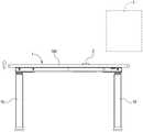
图1A为本发明第一具体实施例的升降设备及可携式装置架构图。FIG. 1A is a structural diagram of a lifting device and a portable device according to a first embodiment of the present invention.
图1B为本发明第一具体实施例的升降设备及可携式装置示意图。1B is a schematic diagram of a lifting device and a portable device according to the first embodiment of the present invention.
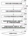
图2为本发明第一具体实施例的升降设备控制方法流程图。FIG. 2 is a flowchart of a control method for a lifting device according to a first specific embodiment of the present invention.
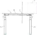
图3A为本发明第一具体实施例的升降设备第一升降示意图。FIG. 3A is a schematic diagram of the first lifting and lowering of the lifting device according to the first embodiment of the present invention.
图3B为本发明第一具体实施例的升降设备第二升降示意图。3B is a schematic diagram of a second lifting and lowering of the lifting device according to the first embodiment of the present invention.
图3C为本发明第一具体实施例的升降设备第三升降示意图。3C is a schematic diagram of a third lifting and lowering of the lifting device according to the first embodiment of the present invention.
图4为本发明第二具体实施例的升降设备控制方法流程图。FIG. 4 is a flowchart of a control method for a lifting device according to a second embodiment of the present invention.
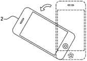
图5A为本发明第一具体实施例的升降控制操作第一示意图。5A is a first schematic diagram of a lift control operation according to the first embodiment of the present invention.
图5B为本发明第一具体实施例的升降控制操作第二示意图。5B is a second schematic diagram of the lift control operation according to the first embodiment of the present invention.
图5C为本发明第一具体实施例的升降控制操作第三示意图。FIG. 5C is a third schematic diagram of the lift control operation according to the first embodiment of the present invention.
图5D为本发明第一具体实施例的升降控制操作第四示意图。FIG. 5D is a fourth schematic diagram of the lifting control operation according to the first embodiment of the present invention.
图5E为本发明第一具体实施例的控制前操作示意图。FIG. 5E is a schematic diagram of a pre-control operation according to the first specific embodiment of the present invention.
图6为本发明第二具体实施例的升降设备及可携式装置架构图。FIG. 6 is a structural diagram of a lifting device and a portable device according to a second embodiment of the present invention.
图7为本发明第三具体实施例的升降设备控制方法流程图。FIG. 7 is a flowchart of a control method for a lifting device according to a third embodiment of the present invention.
图8A为本发明第四具体实施例的升降设备及可携式装置第一示意图。8A is a first schematic diagram of a lifting device and a portable device according to a fourth embodiment of the present invention.
图8B为本发明第四具体实施例的升降设备及可携式装置第二示意图。8B is a second schematic diagram of the lifting equipment and the portable device according to the fourth embodiment of the present invention.
图9A为本发明第五具体实施例的升降设备及可携式装置第一示意图。9A is a first schematic diagram of a lifting device and a portable device according to a fifth embodiment of the present invention.
图9B为本发明第五具体实施例的升降设备及可携式装置第二示意图。9B is a second schematic diagram of the lifting equipment and the portable device according to the fifth embodiment of the present invention.
图10A为本发明第六具体实施例的升降设备及可携式装置第一示意图。10A is a first schematic diagram of a lifting device and a portable device according to a sixth embodiment of the present invention.
图10B为本发明第六具体实施例的升降设备及可携式装置第一示意图。10B is a first schematic diagram of a lifting device and a portable device according to a sixth embodiment of the present invention.
图11A为本发明第七具体实施例的升降设备及可携式装置第一示意图。11A is a first schematic diagram of a lifting device and a portable device according to a seventh embodiment of the present invention.
图11B为本发明第七具体实施例的升降设备及可携式装置第二示意图。其中,附图标记FIG. 11B is a second schematic diagram of the lifting equipment and the portable device according to the seventh embodiment of the present invention. where the reference number
1…升降设备1…Lifting equipment
10…控制盒10…Control Box
100…控制模块100…Control Module
102…信号传输模块102…Signal transmission module
104…存储模块104…Storage module
106…待机模块106…Standby module
12…驱动模块12…Driver module
14…第一人机接口14…The first human-machine interface
16…致动结构16…actuating structure
160…伸缩结构160…Telescopic structure
180…承载结构180…bearing structure
182…支撑座182…Support seat
184…容置空间184…Accommodating space
2、2’、2”、80、82、84、86、90、1000、1100…可携式装置2, 2', 2", 80, 82, 84, 86, 90, 1000, 1100...Portable devices
20…处理器20…processor
22…倾斜感测器22…Tilt sensor
24…第二人机接口24…Second man-machine interface
26…信号传输器26…Signal Transmitter
28…存储器28…memory
30…待机单元30…Standby unit
3…柜子3…Cabinet
40…电视40…TV
S20-S30…第一碰撞侦测及防撞毁步骤S20-S30...The first collision detection and anti-collision steps
S220-S226…控制步骤S220-S226...Control steps
S70-S86…第二碰撞侦测及防撞毁步骤S70-S86…Second Collision Detection and Anti-Crash Steps
具体实施方式Detailed ways
下面结合附图和具体实施例对本发明技术方案进行详细的描述,以更进一步了解本发明的目的、方案及功效,但并非作为本发明所附权利要求保护范围的限制。The technical solution of the present invention will be described in detail below in conjunction with the accompanying drawings and specific embodiments, so as to further understand the purpose, solution and effect of the present invention, but it is not intended to limit the protection scope of the appended claims of the present invention.
为明确说明本发明的技术内容,于后续说明中,主要是以升降设备是电动桌为例来说明本发明技术内容,但不应以此局限本发明的范围。本发明所属技术领域技术人员可依其需求,任意将本发明所揭露的可携式装置及升降设备控制方法用于任何类型的升降设备(如电动电视架、电动柜、电动椅或电动床)。In order to clearly illustrate the technical content of the present invention, in the following description, the lifting device is an electric desk as an example to describe the technical content of the present invention, but this should not limit the scope of the present invention. Those skilled in the art to which the present invention pertains can arbitrarily apply the portable device and the lifting device control method disclosed in the present invention to any type of lifting device (such as an electric TV stand, an electric cabinet, an electric chair or an electric bed) according to their needs. .
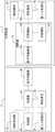
首请同时参阅图1A及图1B,图1A为本发明第一具体实施例的升降设备及可携式装置架构图,图1B为本发明第一具体实施例的升降设备及可携式装置示意图。于本实施例中,升降设备是电动桌。Please refer to FIGS. 1A and 1B at the same time. FIG. 1A is a structural diagram of a lifting device and a portable device according to a first embodiment of the present invention, and FIG. 1B is a schematic diagram of the lifting device and the portable device according to the first embodiment of the present invention. . In this embodiment, the lifting device is an electric table.
如图所示,本发明揭露一种可携式装置2,可与外部的一升降设备1进行互动。具体而言,当该可携式装置2静置或固定于该升降设备1的一承载结构180(于本实施例中,承载结构180是桌面)且该升降设备1正进行一升降动作时,该升降设备1可经由该可携式装置2的一倾斜感测器22来实现一碰撞侦测功能,并于侦测到碰撞时自行启动一防撞毁机制。较佳地,该可携式装置2是一使用者所持有的内建有该倾斜感测器22的智能型手机、平板电脑或穿戴式装置(如智能型手表、智能型眼镜、智能型手环或智能型戒指),但不以此限定。As shown in the figure, the present invention discloses a
接着说明该升降设备1的主要架构。该升降设备1可包括一控制盒10、至少一驱动模块12、一第一人机接口14及至少一致动结构16(于本实施例中,制动结构16是桌脚),其中该致动结构16是可伸缩的,并连接于该承载结构180以支撑该承载结构180并与该承载结构180连动,该致动结构16可受该驱动模块12的驱动而进行伸缩。Next, the main structure of the
该驱动模块12可调整该致动结构16的长度。具体而言,该驱动模块12包括一马达(图未标示),该致动结构16包括连接该马达并受该马达控制的一伸缩结构160。当该马达运转时,可带动该驱动模块12的多个驱动元件(如齿轮,图未标示),而使该伸缩结构160(如一推杆结构)伸长(即增加该致动结构16的长度以抬升该承载结构180)或缩短(即减少该致动结构16的长度以降低该承载结构180)。The driving
该第一人机接口14(如触控荧幕或按键)用以感测来自该使用者的一升降控制操作,并触发对应该升降控制操作的一升降控制信号。The first man-machine interface 14 (eg, a touch screen or a button) is used to sense a lift control operation from the user, and trigger a lift control signal corresponding to the lift control operation.
该控制盒10包括一信号传输模块102、一存储模块104及电性连接上述元件、该驱动模块12及该第一人机接口14的一控制模块100。The
该信号传输模块102用以对外传输信号。较佳地,该信号传输模块102是无线传输模块(如Wi-Fi传输模块、蓝芽传输模块、Zigbee传输模块、红外线传输模块或NFC传输模块)或有线传输模块(如USB传输模块或UART传输模块),但不以此限定。The
该存储模块104用以储存数据。该控制模块100用以控制该升降设备1。并且,该控制模块100可自该第一人机接口14接收该升降控制信号或经由该信号传输模块102自外部接收另一升降控制信号,并依据收到的该升降控制信号控制该驱动模块12调整该致动结构16的长度。The
值得一提的是,虽于本实施例中,是以该升降设备1包括两组该致动结构16(即一对桌脚)为例来进行说明,但不应以此为限,该致动结构16的数量可依需求任意修改。It is worth mentioning that, although in this embodiment, the
接着说明该可携式装置2的主要结构。该可携式装置2可包括该倾斜感测器22、一信号传输器26、一存储器28及电性连接上述元件的一处理器20。Next, the main structure of the
该倾斜感测器22主要用以感测该可携式装置2的机身当前的一倾斜角度。较佳地,该倾斜感测器22是陀螺仪、电子罗盘、加速度计或电子水平仪,但不以此限定。The
该信号传输器26用以对外通讯。较佳地,该信号传输器26是无线传输器(如Wi-Fi传输器、蓝芽传输器、Zigbee传输器、红外线传输器或NFC传输器)或有线传输器(如USB传输器或UART传输器),但不以此限定。该处理器20用以控制该可携式装置2。The
较佳地,该可携式装置2可更包括一壳体,包覆该可携式装置2的各元件以提供保护。Preferably, the
较佳地,该可携式装置2可更包括电性连接该处理器20的一第二人机接口24及一存储器28。第二人机接口24用以感测该使用者的操作,并触发对应的该升降控制信号,存储器28可作为储存媒体,用以提供该使用者选择性存取外部的信息或文件。该第二人机接口24是触控荧幕、按键、触控板或触发器,但不以此限定。Preferably, the
较佳地,该处理器20是与该存储器28可设置于同一模块中(如单晶片系统(Systemon Chip,SoC)或设置于同一中央处理器(CPU)或该处理器20是内建该存储器28),但不以此限定,该处理器20亦可与该存储器28分离设置。Preferably, the
于本发明的另一实施例中,是使用该可携式装置2来进行碰撞侦测。具体而言,于本实施例中,该升降设备1可为非智能型的升降设备(如仅可接受外部手动控制而无法进行自动升降控制的升降设备)。该可携式装置2于收到该升降控制信号后可执行前述碰撞侦测,并于侦测碰撞时发送控制信号(如该停止控制信号)至外部的该升降设备1以藉由控制该升降设备1停止升降来实现该防撞毁机制。藉此,该使用者仅须购买可携式装置,即可使现有的升降设备升级为具有碰撞侦测功能及防撞毁机制的智能型升降设备,而可有效降低升级成本。In another embodiment of the present invention, the
较佳地,该可携式装置2是经由一传输线连接该升降设备1。当该升降设备1开始升降时,会经由该传输线发送该升降控制信号(如该第一人机接口14所触发的该升降控制信号)至该可携式装置2。该可携式装置2是于收到来自该升降设备1的该升降控制信号后才开始进行碰撞侦测。Preferably, the
或者,该可携式装置2是于收到该第二人机接口24所触发的该升降控制信号后,发送该升降控制信号至该升降设备1并同时开始进行碰撞侦测。Alternatively, after receiving the lift control signal triggered by the second man-
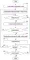
续请同时参阅图2,为本发明第一具体实施例的升降设备控制方法流程图。具体而言,该升降设备1的该存储模块104储存有一第一电脑程序(图未标示)。该可携式装置2的该存储器28储存有一第二电脑程序(图未标示)。当该控制模块100执行该第一电脑程序且该处理器20执行该第二电脑程序时,可共同执行下列用以实现该碰撞侦测功能及执行该防撞毁机制的各步骤。Please refer to FIG. 2 at the same time, which is a flow chart of the control method of the lifting device according to the first embodiment of the present invention. Specifically, the
值得一提的是,虽于后续说明中是以该可携式装置2为主词来进行说明(如“该可携式装置2取得...”、“该可携式装置2感测...”或“该可携式装置2判断...”等等),但本发明所属技术领域技术人员应知悉该可携式装置2实际上是于执行该第二电脑程序后,受该第二电脑程序控制而进行上述动作。It is worth mentioning that, although the
步骤S20:使外部的该可携式装置2与该升降设备1建立一连接。具体而言,该可携式装置2可经由该信号传输器26发出一连线请求至该升降设备1的该信号传输模块102以请求建立该连接,或者,该升降设备1可经由该信号传输模块102发出该连线请求至该可携式装置2的该信号传输器26以请求建立连接。较佳地,该连接可为无线连接(如蓝芽无线连接、Wi-Fi无线连接、Zigbee无线连接、红外线无线连接或NFC无线连接)或有线连接(如USB有线连接或UART有线),但不以此限定。Step S20 : establishing a connection between the external
步骤S22:控制该升降设备1的该驱动模块12来使该升降设备1的该致动结构16朝一第一伸缩方向伸缩(如向上伸长)。具体而言,该升降设备1可依据自该第一人机接口14或自该可携式装置2收到的该升降控制信号来控制该驱动模块12进行上述伸缩动作。Step S22 : controlling the driving
值得一提的是,为实现该碰撞侦测功能,于该升降设备1进行上述伸缩动作时,该可携式装置2需同时被静置或固定于该升降设备1的该承载结构180,以使后续取得的该倾斜角度可真实反映该承载结构180当时的一倾斜状态。It is worth mentioning that, in order to realize the collision detection function, when the
较佳地,该可携式装置2可被该使用者以任意摆放角度静置或固定于该承载结构180的任何位置。举例来说,该可携式装置2可被平放或粘贴于该承载结构180(如图1B所示,可携式装置2被平放于桌面)、被斜放置于该承载结构180上的一支撑座182(如图1B所示可携式装置2’)或被放置于该承载结构180的一容置空间184(如图1B所示可携式装置2”,该容置空间184可为但不限于抽屉或凹槽)。Preferably, the
步骤S24:判断伸缩动作是否完成。较佳地,该可携式装置2可经由该倾斜感测器22感测该承载结构180是否正在升降以判断伸缩动作是否完成(如依据感测到的连续时间的加速度变化、角加速度变化、磁倾角变化或感测电压变化进行判断)、经由与该升降设备1进行通讯来判断伸缩动作是否完成(如依据是否自升降设备1收到一操作完成信号进行判断)或计时一伸缩所需时间是否经过来判断伸缩动作是否完成。若伸缩动作未完成,则执行步骤S26。否则,结束该承载结构控制方法。Step S24: Determine whether the telescopic action is completed. Preferably, the
步骤S26:该可携式装置2自该倾斜感测器22取得当前的该倾斜角度。Step S26 : the
较佳地,该可携式装置2是自该倾斜感测器22取得当前的一倾斜感测值,如角加速度(若该倾斜感测器22是陀螺仪)、三轴加速度(若该倾斜感测器22是三轴加速度计)、磁倾角(若该倾斜感测器22是电子罗盘)或感测电压(若该倾斜感测器22是电子水平仪),并依据该倾斜感测值计算该倾斜角度。Preferably, the
于本发明的另一实施例中,该可携式装置2可先于上述伸缩动作开始前,自该倾斜感测器22取得当时的该倾斜角度,并作为一初始角度。接着,于上述伸缩动作进行时,该可携式装置2可依据该初始角度及当前的该倾斜角度(下称该当前角度)计算实际的该倾斜角度。举例来说,若该初始角度为60度(如该手持式装置2’被放置于60度的该支撑座182上),该当前角度为61度,则可计算出实际的该倾斜角度为1度。In another embodiment of the present invention, the
藉此,即便该可携式装置2未平放于该承载结构180(即该初始角度不为0度),本发明仍可取得正确的该倾斜角度。Therefore, even if the
步骤S28:判断该承载结构180是否倾斜。具体而言,该可携式装置2可依据取得的该倾斜角度判断该承载结构180是否倾斜。Step S28: Determine whether the bearing
较佳地,该可携式装置2是于该倾斜角度不小于一临界角度(如0.3度)时判定该承载结构180倾斜,认定该承载结构180发生碰撞,并经由该信号连接发送一停止信号至该升降设备1以执行该防撞毁机制。Preferably, the
或者,该可携式装置2是依据该倾斜角度计算一倾斜速度,并于该倾斜速度改变时判定该桌面承载结构180倾斜,认定该桌面承载结构180发生碰撞。Alternatively, the
值得一提的是,当该承载结构180发生碰撞(如于伸缩该致动结构16的期间碰撞到障碍物)时,该承载结构180及放置于该承载结构180的该可携式装置2会共同倾斜并改变速度。因此,本发明藉由该可携式装置2计算的该倾斜角度(或倾斜速度)来判断该承载结构180是否倾斜以判断该承载结构180是否发生碰撞,可有效实现该碰撞侦测功能。It is worth mentioning that when the bearing
若判断该承载结构180倾斜,则执行步骤S30以执行该防撞毁机制。否则,再次执行步骤S24。If it is determined that the bearing
步骤S30:控制该驱动模块12来使该致动结构16停止朝该第一伸缩方向伸缩。具体而言,该升降设备1于收到该停止信号后,强制控制该驱动模块12来使该致动结构16停止上述伸缩动作,以避免因该承载结构180碰撞障碍物后仍继续升降而造成毁损。Step S30 : controlling the driving
更进一步地,该升降设备1于该致动结构16停止朝该第一伸缩方向伸缩后,可进一步控制该驱动模块12来使该致动结构16朝与该第一伸缩方向(如向上)相反的一第二伸缩方向伸缩一第二伸缩距离(如向下缩短5公分),以使该承载结构180与障碍物分离。Furthermore, after the
值得一提的是,虽于本实施例中,是以于伸缩该致动结构的期间,自该倾斜感测器22取得当前的该倾斜角度为例来进行说明,但取得该倾斜角度的时间点不应以此为限。于本发明的另一实施例中,是于该可携式装置2与该升降设备1建立该无线连接或该有线连接后,即持续自该倾斜感测器22取得当前的该倾斜角度,以判断该承载结构是否倾斜或该可携式装置2是否接受该升降控制操作(容后详述)。It is worth mentioning that although in this embodiment, the current inclination angle is obtained from the
值得一提的是,虽于本实施例中,用以实现该碰撞侦测功能的该步骤S24-S28是由该可携式装置2执行,但不以此限定。于本发明的另一实施例中,该步骤S24-S28亦可由该升降设备1执行。It is worth mentioning that, although in this embodiment, the steps S24-S28 for realizing the collision detection function are performed by the
具体而言,于该步骤S24中,该升降设备1可经由监控该驱动模块12来判断伸缩动作是否完成。Specifically, in step S24 , the
于该步骤S26中,该升降设备1是经由该信号连接自该可携式装置2取得该倾斜角度。换句话说,于本实施例中,该可携式装置2是如同一外接的倾斜感测器,仅传送所取得的该倾斜角度至该升降设备1,而不对该倾斜角度进行判断处理(即不依据该倾斜角度判断该承载结构180是否发生碰撞)。In the step S26, the
于该步骤S28中,该升降设备1是依据自该可携式装置2收到的该倾斜角度判断该承载结构180是否倾斜,并于判定该承载结构180倾斜时,认定该承载结构180发生碰撞,并发送该停止信号至该驱动模块12以停止伸缩该致动结构以执行该防撞毁机制。In the step S28, the
续请同时参阅图1A至图3C,图3A为本发明第一具体实施例的第一升降设备升降示意图,图3B为本发明第一具体实施例的第二升降设备升降示意图,图3C为本发明第一具体实施例的第三升降设备升降示意图,用以示例性说明本发明的升降设备控制方法如何实现该碰撞侦测功能及执行该防撞毁机制。Please refer to FIGS. 1A to 3C at the same time. FIG. 3A is a schematic diagram of the lifting and lowering of the first lifting device according to the first embodiment of the present invention. FIG. 3B is a schematic diagram of the lifting and lowering of the second lifting device according to the first embodiment of the present invention. A schematic diagram of the third lifting device lifting and lowering according to the first embodiment of the invention is used to illustrate how the control method of the lifting device of the present invention realizes the collision detection function and executes the collision avoidance mechanism.
于本例子中,该升降设备1是电动桌,并放置于一柜子3下方。如图3A所示,当该升降设备1于一般静止状态时,该承载结构180是水平状态且不接触该柜子3。并且,该使用者可操作内建有该倾斜感测器22的该可携式装置2以连接与该升降设备1,并将连接完成的该可携式装置2平放于水平状态的该承载结构180上,以作为该升降设备1的外接倾斜感测器。In this example, the
接着,如图3B所示,该使用者可经由该第一人机接口14或该第二人机接口24控制该升降设备1伸长该致动结构16(以桌脚为例)以抬升该承载结构180(以桌面为例)至适当高度。并且,于伸长该致动结构16的期间,该升降设备1可持续自该可携式装置2取得该倾斜角度,以判断该承载结构180是否发生碰撞。Next, as shown in FIG. 3B , the user can control the
接着,如图3C所示,当该承载结构180被持续抬升而碰撞到上方的该柜子3时,该承载结构180将自水平状态转变为倾斜状态,并连带使放置于该承载结构180上的该可携式装置2亦呈现倾斜状态。与此同时,该可携式装置2取得的该倾斜角度将会不同(如该倾斜角度自0度变为1度)。据此,该可携式装置2可判定该承载结构180发生碰撞,并发送该停止信号制该升降设备1以使该升降设备1执行该防撞毁机制(即停止伸长该致动结构16)。并且,该升降设备1于停止伸长该致动结构16后可进一步缩短该致动结构16以降低该承载结构180,直到收到该可携式装置2于判定所取得的该倾斜角度恢复正常(即该承载结构180转为水平状态)时所发送的另一该停止信号。藉此,可避免该承载结构180及该柜子3因碰撞所产生的持续挤压而造成毁损。Next, as shown in FIG. 3C , when the supporting
续请参阅图4,为本发明第二具体实施例的升降设备控制方法流程图。于本实施例中,该步骤S22更包括下列步骤:Please refer to FIG. 4 , which is a flowchart of a control method for a lifting device according to a second embodiment of the present invention. In this embodiment, the step S22 further includes the following steps:
步骤S220:该可携式装置2接收该升降控制操作。较佳地,该可携式装置2于执行该第二电脑程序后,可于该第二人机接口24显示一图形使用者接口(GUI),并经由该图形使用者接口感测该升降控制操作。Step S220: The
请一并参阅图5A至图5D,图5A为本发明第一具体实施例的第一升降控制操作示意图,图5B为本发明第一具体实施例的第二升降控制操作示意图,图5C为本发明第一具体实施例的第三升降控制操作示意图,图5D为本发明第一具体实施例的第四升降控制操作示意图。Please refer to FIGS. 5A to 5D together. FIG. 5A is a schematic diagram of a first lift control operation according to the first embodiment of the present invention, FIG. 5B is a schematic diagram of a second lift control operation according to the first embodiment of the present invention, and FIG. 5C is a schematic diagram of the first lift control operation of the first embodiment of the present invention. FIG. 5D is a schematic diagram of a fourth lift control operation according to the first embodiment of the present invention. FIG.
于本发明的另一实施例中,该可携式装置2是经由该倾斜感测器22来感测该升降控制操作。具体而言,该可携式装置2于执行该第二电脑程序后,可经由该倾斜感测器22感测该升降控制操作。较佳地,该升降控制操作是于该承载结构180上水平地移动或转动该可携式装置2。In another embodiment of the present invention, the
举例来说,如图5A所示,该使用者可朝一第一平移方向(以朝上为例)平移该可携式装置2以输入该升降控制操作(下称该第一升降控制操作)。或者,如图5B所示,该使用者可朝与该第一平移方向相反的一第二平移方向(以朝下为例)平移该可携式装置2以输入该升降控制操作(下称该第二升降控制操作)。或者,如图5C所示,该使用者可朝一第一旋转方向(以逆时针旋转为例)水平地旋转该可携式装置2以输入该升降控制操作(下称该第三升降控制操作)。或者,如图5D所示,该使用者可朝与该第一旋转方向相反的一第二旋转方向(以顺时针旋转为例)平行地旋转该可携式装置2以输入该升降控制操作(下称该第四升降控制操作)。For example, as shown in FIG. 5A , the user can translate the
值得一提的是,该第一升降控制操作及该第二升降控制操作可分别对应至二相关的功能(如伸长该致动结构16及缩短该致动结构16)。该第三升降控制操作及该第四升降控制操作可分别对应至另外二相关的功能(如增加一伸缩速度及减少该伸缩速度)。本发明藉由提供更直觉的输入方式,可有效提升使用者体验。It is worth mentioning that the first lifting control operation and the second lifting control operation can respectively correspond to two related functions (eg, extending the
于本发明的另一实施例中,更提供一防误触功能。具体而言,该使用者于输入该升降控制操作前,需先输入一控制前操作,以使该可携式装置2识别当前感测的该升降控制操作非为该使用者误触。较佳地,该控制前操作可为按下该可携式装置2的特定按键(如电源键)、点击该可携式装置2的触控荧幕的特定位置、输入密码、解除该可携式装置2的荧幕锁或以特定方式移动该可携式装置2,但不以此限定。In another embodiment of the present invention, an anti-mistouch function is further provided. Specifically, before inputting the lifting control operation, the user needs to input a pre-control operation, so that the
请一并参阅图5E,为本发明第一具体实施例的控制前操作示意图,用以示例性说明该控制前操作。于本例子中,是以该控制前操作为以特定方式移动该可携式装置2为例。具体而言,于进行该升降控制操作前,该使用者可先朝一第一操作方向(以朝左为例)平移该可携式装置2,再朝与该第一操作方向相反的一第二操作方向(以朝右为例)平移该可携式装置2以输入该控制前操作。Please also refer to FIG. 5E , which is a schematic diagram of the pre-control operation according to the first embodiment of the present invention, which is used to exemplarily illustrate the pre-control operation. In this example, the pre-control operation is to move the
较佳地,该可携式装置2仅依据方向来判断当前感测的操作为何,而不依据距离、移动始末点来进行判断。藉此,可提供更直觉的输入方式。Preferably, the
步骤S222:该可携式装置2产生对应所感测的该升降控制操作的该升降控制信号,并经由该信号连接传送所产生的该升降控制信号至该升降设备1。Step S222 : The
较佳地,该使用者或该第二电脑程序的一提供者可于事前进行设定,以将不同的升降控制操作分别对应至不同的该升降控制信号。藉此,该可携式装置2于识别所感测的该升降控制操作后,可产生对应的该升降控制信号,并传送至该升降设备1。Preferably, the user or a provider of the second computer program can set in advance to correspond different lifting control operations to different lifting control signals respectively. Thereby, the
举例来说,该第一升降控制操作可被对应至用以控制该致动结构16伸长的该升降控制信号,该第二升降控制操作可被对应至用以控制该致动结构16缩短的该升降控制信号,该第三升降控制操作可被对应至用以减少该伸缩速度的该升降控制信号,该第四升降控制操作可被对应至用以增加该伸缩速度的该升降控制信号。For example, the first lift control operation may be corresponding to the lift control signal for controlling the elongation of the
较佳地,该使用者或该第二电脑程序的该提供者还可事前设定一预设控制前操作,该可携式装置2于判断所感测的该控制前操作符合该预设控制前操作时,才会接受该升降控制操作并产生对应的该升降控制信号。藉此,本发明可有效避免该使用者误触。Preferably, the user or the provider of the second computer program can also set a preset pre-control operation in advance, and the
步骤S224:该升降设备1依据所收到的该升降控制信号决定该第一伸缩方向(如向上伸长或向下缩短)、一第一伸缩距离或该伸缩速度。并且,该升降设备1可进一步依据一预设伸缩方向(如当前的伸缩方向)、一预设伸缩距离(如10公分)或一预设伸缩速度(如每秒5公分)来决定未被决定的该第一伸缩方向、该第一伸缩距离或该伸缩速度。Step S224 : The lifting
举例来说,若该升降控制信号为“向上伸长”,则该升降设备1可决定该第一伸缩方向为“向上伸长”,并可将该预设伸缩距离(如10公分)作为该第一伸缩距离,并将该预设伸缩速度作为该伸缩速度。藉此,即便该升降控制信号仅指示部分的伸缩参数,该升降设备1亦可自行获得所有伸缩参数以于后续步骤中可有效控制该致动结构16伸缩。For example, if the lift control signal is "extended upward", the
于另一例子中,若该升降控制信号为“增加伸缩速度”,则该升降设备1可依据“增加伸缩速度”的该升降控制信号将该预设伸缩速度或一当前伸缩速度增加一单位(如每秒2公分),并可将该预设伸缩方向作为该伸缩方向,并将该预设伸缩距离(如10公分)作为该第一伸缩距离。In another example, if the lift control signal is "increase telescopic speed", the
步骤S226:该升降设备1依据所决定的该伸缩速度、该第一伸缩方向或该第一伸缩距离控制该驱动模块12来使该致动结构16定速伸缩。具体而言,该升降设备1是控制该驱动模块12来使该致动结构16朝该第一伸缩方向以该伸缩速度定速伸缩该第一伸缩距离。Step S226 : The lifting
值得一提的是,本发明更提供一即时控制功能。具体而言,于该致动结构16的伸缩期间(如步骤S24的“否”选项),该可携式装置2亦可感测来自该使用者的该承载结构感测操作,产生并传送对应的该升降控制信号至该升降设备1以使该升降设备1即时依据所收到的该升降控制信号调整该致动结构16伸缩(如即时改变该第一伸缩方向、该第一伸缩距离或该伸缩速度)。It is worth mentioning that the present invention further provides a real-time control function. Specifically, during the expansion and contraction of the actuating structure 16 (eg, the "No" option in step S24 ), the
举例来说,于该致动结构16的伸缩期间,若该可携式装置2感测到“减少伸缩速度”的该承载结构感测操作,则可产生并传送对应的该升降控制信号至该升降设备1以使该升降设备1即时降低当前的该伸缩速度(如自每秒5公分降为每秒2.5公分)。藉此,该使用者可更精确地且即时地控制该升降设备1的升降。For example, during the expansion and contraction of the
本发明可有效避免因承载结构碰撞障碍物后仍继续升降,而造成承载结构上物品掉落、障碍物毁损或升降设备故障。The present invention can effectively avoid the falling of items on the bearing structure, damage to obstacles or failure of lifting equipment caused by the bearing structure continuing to rise and fall after it collides with the obstacle.
并且,本发明经由使用外部的可携式装置的倾斜感测器来侦测承载结构是否发生碰撞,可使升降设备不须内建倾斜感测器,而可有效降低升降设备的制造成本。Moreover, the present invention detects whether the bearing structure collides by using the tilt sensor of the external portable device, so that the lifting device does not need to have a built-in tilt sensor, thereby effectively reducing the manufacturing cost of the lifting device.
续请参阅图6,为本发明第二具体实施例的升降设备及可携式装置架构图。本实施例的升降设备及可携式装置的各元件是与前述第一实施例相同或相似,于此不再赘述。相较于第一实施例,本实施例的可携式装置2更包括一待机单元30。Please refer to FIG. 6 , which is a structural diagram of a lifting device and a portable device according to a second embodiment of the present invention. The components of the lifting device and the portable device of this embodiment are the same as or similar to those of the first embodiment, and will not be repeated here. Compared with the first embodiment, the
并且,于本实施例中,该待机单元30电性连接该第二人机接口24及该处理器20。具体而言,当该第二人机接口24接受该使用者的操作后,可触发并传送对应的该升降控制信号(即初次升降控制信号)至该待机单元305,以触发该待机单元30导通。接着,该待机单元305可转传该升降控制信号至该处理器20。该处理器20经由信号传输器26发送该初次升降控制信号至该升降设备1。较佳地,该待机单元30是光耦合器,并受该升降控制信号触发而持续导通,但不以此限定。Moreover, in this embodiment, the
并且,于发送该初次升降控制信号后,该处理器20可产生一待机信号至该待机单元30,以使该待机单元30依据该待机信号维持导通一待机时间(如10秒),以使该可携式装置切换至一待机状态。换句话说,当该第二人机接口24感测到该使用者停止操作而停止输出该升降控制信号时,该待机单元30可在该待机时间内维持该第二人机接口24及该处理器20间的导通(即于该待机时间内,该第二人机接口24及该处理器20仍可进行信号传输)。In addition, after sending the initial lift control signal, the
并且,当该第二人机接口24于该待机时间内再次接受该使用者操作时,由于与该处理器20间仍维持导通,该第二人机接口24可立即经由该待机单元30发送对应的该升降控制信号(即二次升降控制信号)至该处理器20,以使该升降设备1可立即依据该二次升降控制信号执行对应动作,无须重新启动。Moreover, when the second man-
值得一提的是,当该可携式装置计算该待机时间结束后,可关闭该待机单元30,以离开该待机状态(如切换至一关机状态或一休眠状态)。较佳地,该处理器20是于该待机时间内持续产生该待机信号至该待机单元30,以使该待机单元30持续维持导通。并且,当该处理器20计算该待机时间结束后,该处理器20停止发送该待机信号至该待机单元30,以使该待机单元30,以使该待机单元30关闭。It is worth mentioning that, when the portable device calculates the end of the standby time, the
本发明经由使可携式装置的待机单元于信号中断后维持导通一段时间,可有效缩短使用者进行二次操作后,可携式装置所需的反应时间,进而提升便利性。并且,本发明经由使可携式装置于待机时间结束后自动离开待机状态以节省电力消耗,可有效避免持续待机而造成电力浪费。The present invention can effectively shorten the response time required by the portable device after the user performs the secondary operation by keeping the standby unit of the portable device on for a period of time after the signal is interrupted, thereby improving the convenience. In addition, the present invention saves power consumption by causing the portable device to automatically leave the standby state after the standby time expires, thereby effectively avoiding power waste caused by continuous standby.
虽于本实施例中待机单元是设置于该可携式装置2,但不以此限定。于本发明的另一实施例中,待机单元亦可设置于该升降设备1(如图6所示的待机模块106),该待机模块106是与该待机单元30相同或相似,于此不再赘述。较佳地,该待机模块106可电性连接该控制模块100、该驱动模块12及该第一人机接口14,并决定三者之间导通或断路。该待机模块106可转传该控制模块100发送的控制信号至该驱动模块12,或转传该第一人机接口14发送的控制信号至该控制模块100,并可如上述该待机单元30运作,以提供一待机功能。Although the standby unit is disposed in the
图7为本发明第三具体实施例的升降设备控制方法流程图。本实施例的升降设备控制方法主要是由图6所示的该升降设备1及该可携式装置2来加以实现。本实施例的升降设备控制方法的步骤S70-S80是与第一实施例的升降设备控制方法的步骤S20-S30相同或相似,于此不再赘述。本实施例与第一实施例差异在于,本实施例更包括下列步骤:FIG. 7 is a flowchart of a control method for a lifting device according to a third embodiment of the present invention. The lifting equipment control method of this embodiment is mainly realized by the
步骤S82:切换至该待机状态。具体而言,于该致动结构停止伸缩(如该升降设备1的升降高度因达该使用者期望高度而停止,或该升降设备1的承载结构该180因启动防撞毁机制而停止)时,该升降设备1或该可携式装置2可自动切换至该待机状态(如发送该待机信号至该待机单元30或该待机模块106以使其持续维持导通)。Step S82: switch to the standby state. Specifically, when the actuating structure stops extending and retracting (for example, the lifting height of the
步骤S84:判断是否接受该使用者操作。具体而言,该升降设备1的该控制模块100可依据是否自该第一人机接口14收到该升降控制信号(即该二次升降控制信号)或自该信号传输模块102收到来自该可携式装置2的该升降控制信号(即该二次升降控制信号)来判断是否接受该使用者操作,并于判断已接受该使用者操作时经由导通的该待机模块106发送所收到的该升降控制信号至该驱动模块12。Step S84: Determine whether to accept the user's operation. Specifically, the
或者,该可携式装置2的该第二人机接口24可感测是否接受该使用者操作,并于接受该使用者操作时产生并经由导通的该待机单元30发送对应的该升降控制信号至该处理器20。Alternatively, the second man-
若感测到接受该使用者操作,则再次执行该步骤S72以伸缩该致动结构;否则,执行步骤S86。If it is sensed that the user operation is accepted, step S72 is performed again to extend and retract the actuating structure; otherwise, step S86 is performed.
步骤S86:计时该待机时间是否结束。若该待机时间未结束,则再次执行步骤S84;否则,结束升降设备控制方法。Step S86: Count whether the standby time is over. If the standby time has not expired, step S84 is performed again; otherwise, the lifting device control method is ended.
较佳地,该控制模块100可计时该待机时间是否结束,并于计时该待机时间结束时,禁能该待机模块106(如发送一禁能信号或停止发送该待机信号)以使该升降设备1切换至该关机状态或该休眠状态。Preferably, the
或者,该处理器20亦可计时该待机时间是否结束,并于计时该待机时间结束时,禁能该待机单元30(如发送该禁能信号或停止发送该待机信号)以使该可携式装置2切换至该关机状态或该休眠状态。Alternatively, the
本发明经由使可携式装置或升降设备自动切换至待机状态,可有效缩短进行二次操作所需的反应时间,进而提升便利性。并且,本发明经由使可携式装置或升降设备于待机时间结束后自动离开待机状态以节省电力消耗,可有效避免持续待机而造成电力浪费。The present invention can effectively shorten the response time required for the secondary operation by automatically switching the portable device or the lifting device to the standby state, thereby improving convenience. In addition, the present invention saves power consumption by causing the portable device or the lifting device to automatically leave the standby state after the standby time expires, thereby effectively avoiding power waste caused by continuous standby.
续请一并参阅图8A及图8B,图8A为本发明第四具体实施例的升降设备及可携式装置第一示意图,图8B为本发明第四具体实施例的升降设备及可携式装置第二示意图。本实施例的可携式装置80、82、84、86是与前述该可携式装置2相对应,于此不再赘述。Please refer to FIGS. 8A and 8B together. FIG. 8A is a first schematic diagram of a lifting device and a portable device according to a fourth embodiment of the present invention, and FIG. 8B is a lifting device and a portable device according to a fourth embodiment of the present invention. Second schematic diagram of the device. The
如图8A所示,于本实施例中,升降设备1是电动电视架,致动结构16为升降柱,承载结构180为电视支撑架并用以支撑电视40。该可携式装置可安装于该升降设备1的该致动结构16上(如可携式装置80所示位置)、该升降设备1顶端(如可携式装置82所示位置)、该承载结构180上(如可携式装置84所示位置)或该电视40上(如可携式装置86所示位置)。较佳地,可携式装置80、82、84、86是以粘贴或元件固定(如使用卡榫固定或使用螺丝固定)方式安装于该升降设备1或电视40。As shown in FIG. 8A , in this embodiment, the
并且,当该升降设备1处于静止状态时,该承载结构180是水平状态。并且,使用者可操作内建有该倾斜感测器22的该可携式装置80、82、84、86以连接该升降设备1,并将连接完成的该可携式装置80、82、84、86安装于该升降设备1或该电视40,以作为该升降设备1的外接碰撞感测器。And, when the
接着,如图8B所示,该使用者可经由该第一人机接口14或该第二人机接口24控制该升降设备1伸长该致动结构16以抬升该承载结构180至适当高度。并且,于伸长该致动结构16的期间,该升降设备1可持续自该可携式装置80、82、84、86取得倾斜角度或加速度,以判断该承载结构180是否倾斜或发生碰撞,并于判断该承载结构180倾斜或发生碰撞时,自动启动该防撞毁机制。Then, as shown in FIG. 8B , the user can control the
续请一并参阅图9A及图9B,图9A为本发明第五具体实施例的升降设备及可携式装置第一示意图,图9B为本发明第五具体实施例的升降设备及可携式装置第二示意图。本实施例的可携式装置90是与前述该可携式装置2相对应,于此不再赘述。Please refer to FIGS. 9A and 9B together. FIG. 9A is a first schematic diagram of a lifting device and a portable device according to a fifth embodiment of the present invention, and FIG. 9B is a lifting device and a portable device according to a fifth embodiment of the present invention. Second schematic diagram of the device. The
如图9A所示,于本实施例中,升降设备1是电动柜,致动结构16为升降柱,承载结构180为可升降柜。该可携式装置可安装于承载结构180上(如可携式装置90所示位置)。较佳地,可携式装置90是以粘贴或元件固定方式安装于该升降设备1。As shown in FIG. 9A , in this embodiment, the
并且,当该升降设备1处于静止状态时,该承载结构180是水平状态。并且,使用者可操作内建有该倾斜感测器22的该可携式装置90以连接该升降设备1,并将连接完成的该可携式装置90安装于该升降设备1,以作为该升降设备1的外接碰撞感测器。And, when the
接着,如图9B所示,该使用者可经由该第一人机接口14或该第二人机接口24控制该升降设备1伸长该致动结构16以使该承载结构180下降至适当高度。并且,于伸长该致动结构16的期间,该升降设备1可持续自该可携式装置2取得倾斜角度或加速度,以判断该承载结构180是否倾斜或发生碰撞,并于判断该承载结构180倾斜或发生碰撞时,自动启动该防撞毁机制。Next, as shown in FIG. 9B , the user can control the
续请一并参阅图10A及图10B,图10A为本发明第六具体实施例的升降设备及可携式装置第一示意图,图10B为本发明第六具体实施例的升降设备及可携式装置第一示意图。本实施例的可携式装置1000是与前述该可携式装置2相对应,于此不再赘述。Please refer to FIGS. 10A and 10B together. FIG. 10A is a first schematic diagram of a lifting device and a portable device according to a sixth embodiment of the present invention, and FIG. 10B is a lifting device and a portable device according to a sixth embodiment of the present invention. The first schematic diagram of the device. The
如图10A所示,于本实施例中,升降设备1是电动椅,致动结构16为升降柱,承载结构180为可调整腿部支撑垫。该可携式装置可安装于承载结构180上(如可携式装置1000所示位置)。较佳地,可携式装置1000是以粘贴或元件固定方式安装于该升降设备1。As shown in FIG. 10A , in this embodiment, the
并且,当该升降设备1处于静止状态时,该承载结构180的倾斜角度维持定值。并且,使用者可操作内建有该倾斜感测器22的该可携式装置1000以连接该升降设备1,并将连接完成的该可携式装置1000安装于该升降设备1,以作为该升降设备1的外接碰撞感测器。Moreover, when the
接着,如图10B所示,该使用者可经由该第一人机接口14或该第二人机接口24控制该升降设备1伸长该致动结构16以使该承载结构180抬升至适当高度。并且,于抬升该承载结构180的期间,该升降设备1可持续自该可携式装置1000取得该倾斜角度或加速度,以判断该承载结构180是否发生碰撞,并于判断该承载结构180发生碰撞时,自动启动该防撞毁机制。Next, as shown in FIG. 10B , the user can control the
续请一并参阅图11A及图11B,图11A为本发明第七具体实施例的升降设备及可携式装置第一示意图,图11B为本发明第七具体实施例的升降设备及可携式装置第二示意图。本实施例的可携式装置1100是与前述该可携式装置2相对应,于此不再赘述。Please refer to FIGS. 11A and 11B together. FIG. 11A is a first schematic diagram of a lifting device and a portable device according to a seventh embodiment of the present invention, and FIG. 11B is a lifting device and a portable device according to a seventh embodiment of the present invention. Second schematic diagram of the device. The
如图11A所示,于本实施例中,升降设备1是电动床,致动结构16为升降柱,承载结构180为可调整头垫。该可携式装置可安装于承载结构180上(如可携式装置1100所示位置)。较佳地,可携式装置1100是以粘贴或元件固定方式安装于该升降设备1。As shown in FIG. 11A , in this embodiment, the
并且,当该升降设备1处于静止状态时,该承载结构180的倾斜角度维持定值。并且,使用者可操作内建有该倾斜感测器22的该可携式装置1100以连接该升降设备1,并将连接完成的该可携式装置1100安装于该升降设备1,以作为该升降设备1的外接碰撞感测器。Moreover, when the
接着,如图11B所示,该使用者可经由该第一人机接口14或该第二人机接口24控制该升降设备1伸长该致动结构16以使该承载结构180抬升至适当高度。并且,于抬升该承载结构180的期间,该升降设备1可持续自该可携式装置2取得倾斜角度或加速度,以判断该承载结构180是否发生碰撞,并于判断该承载结构180发生碰撞时,自动启动该防撞毁机制。Next, as shown in FIG. 11B , the user can control the
当然,本发明还可有其它多种实施例,在不背离本发明精神及其实质的情况下,熟悉本领域的技术人员当可根据本发明作出各种相应的改变和变形,但这些相应的改变和变形都应属于本发明所附的权利要求的保护范围。Of course, the present invention can also have other various embodiments, without departing from the spirit and essence of the present invention, those skilled in the art can make various corresponding changes and modifications according to the present invention, but these corresponding Changes and deformations should belong to the protection scope of the appended claims of the present invention.
Claims (18)
Applications Claiming Priority (6)
| Application Number | Priority Date | Filing Date | Title |
|---|---|---|---|
| TW104127571ATWI642389B (en) | 2015-08-24 | 2015-08-24 | Electric-lifting table and method for controlling the same |
| TW104127571 | 2015-08-24 | ||
| TW104138640 | 2015-11-20 | ||
| TW104138640 | 2015-11-20 | ||
| TW105122243 | 2016-07-14 | ||
| TW105122243ATWI642390B (en) | 2015-11-20 | 2016-07-14 | Portable device for controlling electrical adjustable apparatus? and control method for electrical adjustable apparatus |
Publications (2)
| Publication Number | Publication Date |
|---|---|
| CN106483985A CN106483985A (en) | 2017-03-08 |
| CN106483985Btrue CN106483985B (en) | 2020-09-08 |
Family
ID=58010929
Family Applications (1)
| Application Number | Title | Priority Date | Filing Date |
|---|---|---|---|
| CN201610589839.2AActiveCN106483985B (en) | 2015-08-24 | 2016-07-25 | Portable device for controlling lifting equipment and lifting equipment control method |
Country Status (3)
| Country | Link |
|---|---|
| US (2) | US10154736B2 (en) |
| CN (1) | CN106483985B (en) |
| DE (1) | DE102016115244B4 (en) |
Families Citing this family (31)
| Publication number | Priority date | Publication date | Assignee | Title |
|---|---|---|---|---|
| CN106483985B (en)* | 2015-08-24 | 2020-09-08 | 第一传动科技股份有限公司 | Portable device for controlling lifting equipment and lifting equipment control method |
| DE102016101955A1 (en)* | 2016-02-04 | 2017-08-10 | Karsten Laing | Electrically adjustable furniture |
| CN206390562U (en) | 2016-09-23 | 2017-08-11 | 廖良成 | Electric lifting computer desk and its desk |
| US11019920B2 (en) | 2016-09-23 | 2021-06-01 | Varidesk, Llc | Electrically-lifted computer desk and office desk thereof |
| US10602839B2 (en) | 2016-09-29 | 2020-03-31 | Linak A/S | Height adjustable table/desk control mechanism |
| GB2560049B (en)* | 2017-04-06 | 2019-05-22 | Loftrobe Ltd | A wardrobe apparatus |
| CA3056300A1 (en) | 2017-05-15 | 2018-11-22 | Linak A/S | Height-adjustable table |
| JP7263253B2 (en) | 2017-05-15 | 2023-04-24 | リナック エー/エス | electrical operation panel |
| US10842258B2 (en) | 2017-09-18 | 2020-11-24 | Fellowes, Inc. | Variable height platform system |
| CN107990870A (en)* | 2017-12-08 | 2018-05-04 | 杭州精石科技有限公司 | Desktop anti-pinch detection device and detection method |
| CN111655074B (en)* | 2018-01-31 | 2022-09-09 | 奥诗莱格金属技术有限责任公司 | Electric height-adjustable stage and control method thereof |
| WO2018127880A2 (en)* | 2018-03-14 | 2018-07-12 | Logic Studio | Method and apparatus for giving and receiving objects |
| CN110150871A (en)* | 2018-04-02 | 2019-08-23 | 陈治领 | A kind of furred ceiling vertical lift storage bookcase |
| USD879514S1 (en) | 2018-04-16 | 2020-03-31 | Playground Store Limited | Desk |
| USD895325S1 (en) | 2018-04-16 | 2020-09-08 | Playground Store Limited | Desktop with stowed legs |
| CN114376335A (en) | 2018-04-16 | 2022-04-22 | 游乐场商店有限公司 | table system |
| US10779638B2 (en) | 2018-06-04 | 2020-09-22 | Knoll, Inc. | Table height adjustment system and method of using the same |
| CN109452757A (en)* | 2018-12-04 | 2019-03-12 | 嘉兴礼海电气科技有限公司 | One kind being based on electric elevatable table anticollision control system and its collision-proof method |
| CN110025148A (en)* | 2019-05-15 | 2019-07-19 | 乐歌人体工学科技股份有限公司 | A kind of office equipment |
| DE202019002176U1 (en)* | 2019-05-20 | 2019-05-29 | Oelschläger Metalltechnik GmbH | Operating device for a table and table with the same |
| CN114430664B (en) | 2019-09-13 | 2022-10-11 | 爱格升公司 | Workstation Height Adjustment Monitoring |
| US11051632B1 (en)* | 2020-03-10 | 2021-07-06 | Kellie Lantz | Multi-height table and chair set |
| CN111184345B (en)* | 2020-03-13 | 2024-06-25 | 常州市凯迪电器股份有限公司 | Control method and control unit for safe operation of electric table |
| CN112612271A (en)* | 2020-12-15 | 2021-04-06 | 广东智源机器人科技有限公司 | Transport method of carrier, food delivery device and storage medium |
| CN112596520A (en)* | 2020-12-15 | 2021-04-02 | 广东智源机器人科技有限公司 | Method and device for controlling descending of meal delivery equipment, meal delivery equipment and storage medium |
| CN112631291A (en)* | 2020-12-15 | 2021-04-09 | 广东智源机器人科技有限公司 | Method and device for controlling ascending of meal delivery equipment, meal delivery equipment and storage medium |
| CN112612270A (en)* | 2020-12-15 | 2021-04-06 | 广东智源机器人科技有限公司 | Dish delivery control method and device, meal delivery equipment and storage medium |
| CN114352899A (en)* | 2021-12-14 | 2022-04-15 | 深圳市惠康电机制造有限公司 | Multimedia device |
| CN114879752B (en)* | 2022-05-16 | 2024-11-08 | 乐歌人体工学科技股份有限公司 | Storage rack, storage rack level control method, control device and storage medium |
| TWI803397B (en)* | 2022-07-21 | 2023-05-21 | 施權航 | electric bed |
| CN115903627B (en)* | 2022-12-28 | 2023-06-20 | 长兴精石科技有限公司 | Intelligent controller and intelligent control system thereof |
Family Cites Families (22)
| Publication number | Priority date | Publication date | Assignee | Title |
|---|---|---|---|---|
| JPH04220208A (en) | 1990-12-20 | 1992-08-11 | Matsushita Electric Works Ltd | Ascending/descending table |
| JPH0937862A (en) | 1995-08-03 | 1997-02-10 | Og Giken Co Ltd | Sink cabinet with emergency stopper |
| US6392556B2 (en) | 2000-01-18 | 2002-05-21 | David Christopher Tomich | Chair tilt alarm |
| DK1460914T4 (en) | 2001-12-13 | 2021-08-30 | Linak As | An adjustable construction, preferably a piece of furniture and a clamp protection as well as a drive unit therefor |
| AT410626B (en) | 2002-02-26 | 2003-06-25 | Koch Walter Dipl Ing | Work table has controller that reverses direction of rotation of adjustment motor depending on detected parameter and/or motor load change, switches motor off after resulting reverse rotation |
| US7519468B2 (en)* | 2005-02-28 | 2009-04-14 | Research In Motion Limited | System and method for navigating a mobile device user interface with a directional sensing device |
| DE102006013349A1 (en)* | 2006-03-23 | 2007-09-27 | Kostal Industrie Elektrik Gmbh | Multi-part electrically adjustable furniture |
| DE202006018530U1 (en) | 2006-03-23 | 2007-03-01 | Kostal Industrie Elektrik Gmbh | Multipart furniture e.g. table, has safety device that is assigned to inclination sensor, where output signal of sensor is evaluated by safety device for detecting incorrect position of furniture parts e.g. table plates |
| DE102006038558A1 (en) | 2006-08-17 | 2008-04-30 | Vibradorm Gmbh | Electrically adjustable furniture's e.g. office furniture, drive control arrangement, has motor that is controlled with acceleration measured from acceleration sensor, such that movement of furniture can be stopped |
| US10864137B2 (en)* | 2006-09-14 | 2020-12-15 | Ascion, Llc | System and method of an adjustable bed with a vibration motor |
| US8926535B2 (en)* | 2006-09-14 | 2015-01-06 | Martin B. Rawls-Meehan | Adjustable bed position control |
| CN101155363A (en)* | 2006-09-30 | 2008-04-02 | 海尔集团公司 | Method and apparatus for implementing mobile phone control by action induction |
| DE202011003743U1 (en) | 2011-03-10 | 2011-05-05 | Oelschläger Metalltechnik GmbH | Height-adjustable table frame, especially for a desk, and table with selbigem |
| PL2583586T5 (en)* | 2011-10-18 | 2021-10-11 | Kesseböhmer Produktions GmbH & Co. KG | Device for detecting collisions and method |
| CN202698373U (en) | 2012-08-31 | 2013-01-30 | 惠州学院 | Office and learning health care furniture combination capable of being intelligently controlled |
| US9486070B2 (en)* | 2012-10-10 | 2016-11-08 | Stirworks Inc. | Height-adjustable support surface and system for encouraging human movement and promoting wellness |
| WO2015058768A1 (en)* | 2013-05-10 | 2015-04-30 | Linak A/S | Height adjustable table |
| US8996432B1 (en)* | 2013-10-16 | 2015-03-31 | University of Central Oklahoma | Intelligent apparatus for providing personalized configuration of wheelchair tilt and recline |
| TWI614706B (en)* | 2013-12-10 | 2018-02-11 | 深圳市華星光電技術有限公司 | Operation method of portable electronic apparatus |
| EP3031356A1 (en)* | 2014-12-12 | 2016-06-15 | KIH-utveckling AB | Height-adjustable table using eye detection |
| US10004979B2 (en)* | 2015-02-26 | 2018-06-26 | Microsoft Technology Licensing, Llc | Sensor data availability from remote devices |
| CN106483985B (en)* | 2015-08-24 | 2020-09-08 | 第一传动科技股份有限公司 | Portable device for controlling lifting equipment and lifting equipment control method |
- 2016
- 2016-07-25CNCN201610589839.2Apatent/CN106483985B/enactiveActive
- 2016-08-04USUS15/228,872patent/US10154736B2/enactiveActive
- 2016-08-17DEDE102016115244.7Apatent/DE102016115244B4/enactiveActive
- 2018
- 2018-10-31USUS16/177,208patent/US10334961B2/enactiveActive
Also Published As
| Publication number | Publication date |
|---|---|
| US10334961B2 (en) | 2019-07-02 |
| CN106483985A (en) | 2017-03-08 |
| US20170055720A1 (en) | 2017-03-02 |
| DE102016115244A1 (en) | 2017-03-02 |
| DE102016115244B4 (en) | 2019-05-09 |
| US20190059607A1 (en) | 2019-02-28 |
| US10154736B2 (en) | 2018-12-18 |
Similar Documents
| Publication | Publication Date | Title |
|---|---|---|
| CN106483985B (en) | Portable device for controlling lifting equipment and lifting equipment control method | |
| KR102534559B1 (en) | Electronic device and method for communicating thereof | |
| CN106095295B (en) | A processing method and mobile terminal based on fingerprint identification | |
| RU2599536C2 (en) | User interface interaction method and apparatus applied in touchscreen device, and touchscreen device | |
| TWI509497B (en) | Method and system for operating portable devices | |
| JP6204324B2 (en) | Wearable information terminal and charging system | |
| EP3477432B1 (en) | Electronic device, input/output apparatus, and use method of input/output apparatus | |
| US20180203568A1 (en) | Method for Enabling Function Module of Terminal, and Terminal Device | |
| CN102929424A (en) | Mobile terminal control method, device and mobile terminal | |
| KR20180089229A (en) | Display control method, storage medium and electronic device for controlling the display | |
| CN109005262A (en) | A kind of camera control method and terminal | |
| CN103973986A (en) | Focusing and lens switching method based on mobile terminal camera | |
| CN103927117A (en) | Method for quickly lighting up screen and mobile terminal thereof | |
| CN103870772A (en) | Touch screen electronic device and control method thereof | |
| US20140160007A1 (en) | Electronic apparatus, method of controlling the same, and computer-readable recording medium | |
| JP2019532436A (en) | Screen display method and terminal | |
| CN106970752B (en) | Screen capture method and mobile terminal | |
| CN106230069B (en) | A kind of charging method and terminal | |
| TWI642390B (en) | Portable device for controlling electrical adjustable apparatus? and control method for electrical adjustable apparatus | |
| WO2016034080A1 (en) | Boot mode control method and terminal | |
| CN106371595B (en) | Method for calling out message notification bar and mobile terminal | |
| JP2013205896A (en) | Display control device, display control method, and program | |
| WO2014097653A1 (en) | Electronic apparatus, control method, and program | |
| WO2014135125A1 (en) | Method and apparatus for adjusting an input box in a display screen during the switch of display mode | |
| CN102436314B (en) | Cursor positioning method and device for mobile terminal |
Legal Events
| Date | Code | Title | Description |
|---|---|---|---|
| C06 | Publication | ||
| PB01 | Publication | ||
| SE01 | Entry into force of request for substantive examination | ||
| SE01 | Entry into force of request for substantive examination | ||
| GR01 | Patent grant | ||
| GR01 | Patent grant |