CN106470619B - Suture delivery device for suturing tissue - Google Patents
Suture delivery device for suturing tissueDownload PDFInfo
- Publication number
- CN106470619B CN106470619BCN201580017947.6ACN201580017947ACN106470619BCN 106470619 BCN106470619 BCN 106470619BCN 201580017947 ACN201580017947 ACN 201580017947ACN 106470619 BCN106470619 BCN 106470619B
- Authority
- CN
- China
- Prior art keywords
- suture
- needle
- struts
- membrane
- delivery device
- Prior art date
- Legal status (The legal status is an assumption and is not a legal conclusion. Google has not performed a legal analysis and makes no representation as to the accuracy of the status listed.)
- Active
Links
Images


Classifications
- A—HUMAN NECESSITIES
- A61—MEDICAL OR VETERINARY SCIENCE; HYGIENE
- A61B—DIAGNOSIS; SURGERY; IDENTIFICATION
- A61B17/00—Surgical instruments, devices or methods
- A61B17/04—Surgical instruments, devices or methods for suturing wounds; Holders or packages for needles or suture materials
- A61B17/0482—Needle or suture guides
- A—HUMAN NECESSITIES
- A61—MEDICAL OR VETERINARY SCIENCE; HYGIENE
- A61B—DIAGNOSIS; SURGERY; IDENTIFICATION
- A61B17/00—Surgical instruments, devices or methods
- A61B17/0057—Implements for plugging an opening in the wall of a hollow or tubular organ, e.g. for sealing a vessel puncture or closing a cardiac septal defect
- A—HUMAN NECESSITIES
- A61—MEDICAL OR VETERINARY SCIENCE; HYGIENE
- A61B—DIAGNOSIS; SURGERY; IDENTIFICATION
- A61B17/00—Surgical instruments, devices or methods
- A61B17/04—Surgical instruments, devices or methods for suturing wounds; Holders or packages for needles or suture materials
- A61B17/06—Needles ; Sutures; Needle-suture combinations; Holders or packages for needles or suture materials
- A61B17/062—Needle manipulators
- A61B17/0625—Needle manipulators the needle being specially adapted to interact with the manipulator, e.g. being ridged to snap fit in a hole of the manipulator
- A—HUMAN NECESSITIES
- A61—MEDICAL OR VETERINARY SCIENCE; HYGIENE
- A61B—DIAGNOSIS; SURGERY; IDENTIFICATION
- A61B17/00—Surgical instruments, devices or methods
- A61B17/0057—Implements for plugging an opening in the wall of a hollow or tubular organ, e.g. for sealing a vessel puncture or closing a cardiac septal defect
- A61B2017/00637—Implements for plugging an opening in the wall of a hollow or tubular organ, e.g. for sealing a vessel puncture or closing a cardiac septal defect for sealing trocar wounds through abdominal wall
- A—HUMAN NECESSITIES
- A61—MEDICAL OR VETERINARY SCIENCE; HYGIENE
- A61B—DIAGNOSIS; SURGERY; IDENTIFICATION
- A61B17/00—Surgical instruments, devices or methods
- A61B17/0057—Implements for plugging an opening in the wall of a hollow or tubular organ, e.g. for sealing a vessel puncture or closing a cardiac septal defect
- A61B2017/00646—Type of implements
- A61B2017/00663—Type of implements the implement being a suture
Landscapes
- Health & Medical Sciences (AREA)
- Life Sciences & Earth Sciences (AREA)
- Surgery (AREA)
- Heart & Thoracic Surgery (AREA)
- Engineering & Computer Science (AREA)
- Biomedical Technology (AREA)
- Nuclear Medicine, Radiotherapy & Molecular Imaging (AREA)
- Medical Informatics (AREA)
- Molecular Biology (AREA)
- Animal Behavior & Ethology (AREA)
- General Health & Medical Sciences (AREA)
- Public Health (AREA)
- Veterinary Medicine (AREA)
- Cardiology (AREA)
- Surgical Instruments (AREA)
Abstract
Description
Translated fromChinese相关申请Related applications
本申请要求2014年2月7日提交的、美国临时专利申请序列号61/937,089的优先权和权益,该专利申请的全部内容通过引用并入本文中。This application claims priority to and the benefit of US Provisional Patent Application Serial No. 61/937,089, filed February 7, 2014, the entire contents of which are incorporated herein by reference.
技术领域technical field
本公开总体上涉及用于闭合患者身体上的小切口的技术和装置。例如,本公开涉及用于闭合腹腔镜穿刺口的系统、装置和方法,在例如胆囊切除术、阑尾切除术或减肥手术等各种微创外科手术之后需要闭合腹腔镜穿刺口。The present disclosure generally relates to techniques and devices for closing small incisions on a patient's body. For example, the present disclosure relates to systems, devices, and methods for closing laparoscopic punctures required after various minimally invasive surgical procedures, such as cholecystectomy, appendectomy, or bariatric surgery.
背景技术Background technique
腹腔镜手术是一种微创外科手术。其是传统“开腹”手术的替代,且提供最小化术后疼痛、缩短住院时间和残疾时段,以及减少医院和患者二者的成本的益处。Laparoscopic surgery is a minimally invasive surgical procedure. It is an alternative to traditional "open" surgery and offers the benefits of minimizing postoperative pain, shortening hospital stays and periods of disability, and reducing costs for both the hospital and the patient.
全世界每年在例如胆囊切除术、阑尾切除术、减肥手术、妇科手术和泌尿手术领域中进行超过七百五十万例腹腔镜外科手术。然而,由于对于腹腔镜外科手术来说穿刺口疝形成的发生率,所以穿刺口闭合优选地用于大于或等于10 毫米的筋膜切口。穿刺口闭合能够有效地减少疝形成率,从而减少对于疝修补外科手术的需要,疝修补外科手术的估计成本在每个手术US$6,000-10,000之间并且需要三周的恢复时间。所进行的腹腔镜手术中的大约70%具有10毫米或更大的穿刺口。More than 7.5 million laparoscopic surgical procedures are performed every year worldwide in fields such as cholecystectomy, appendectomy, bariatric surgery, gynecological surgery and urological surgery. However, due to the incidence of port hernia formation for laparoscopic surgery, port closure is preferred for fascial incisions greater than or equal to 10 mm. Puncture closure is effective in reducing the rate of hernia formation, thereby reducing the need for hernia repair surgery, which has an estimated cost of US$6,000-10,000 per procedure and requires a three-week recovery time. Approximately 70% of laparoscopic procedures performed have a puncture port of 10 mm or larger.
为了改善这些问题,已经开发了用于缝合穿刺口的技术。尽管有与使用缝线输送装置相关联的益处,但是还存在若干挑战。在缝合针的插入期间,用于穿刺口闭合的装置能够在伤道或切口中旋转、倾斜,以及垂直朝下滑动。如果装置旋转,缝线将横跨伤口以小于理想的180度展开。如果装置在插入期间垂直地滑动,则对于使用腹膜作为针进入肌肉/筋膜层中的参考点的装置来说,期望的肌肉/筋膜层的组织咬合减少。也就是说,如果由于朝下的滑动使得这种装置不接合抵靠腹膜,则到肌肉/筋膜层中的针进入点将比预期位置更低且减少组织咬合。还期望提供一种装置,其构造成以可重复方式部署针,以最小化对操作人员所要求的技能量。相应地,本公开针对用于伤口闭合的系统和方法,其提供这些和其他期望特征。To ameliorate these problems, techniques for suturing punctures have been developed. Despite the benefits associated with using a suture delivery device, there are several challenges. During insertion of the suture needle, the device for puncture closure can be rotated, tilted, and slid vertically downward in the wound or incision. If the device is rotated, the suture will spread across the wound at less than the ideal 180 degrees. If the device slides vertically during insertion, the desired tissue occlusion of the muscle/fascia layer is reduced for devices that use the peritoneum as a reference point for needle entry into the muscle/fascia layer. That is, if such a device does not engage against the peritoneum due to downward sliding, the needle entry point into the muscle/fascia layer will be lower than expected and reduce tissue occlusion. It is also desirable to provide a device that is configured to deploy the needle in a repeatable manner to minimize the amount of skill required of the operator. Accordingly, the present disclosure is directed to systems and methods for wound closure that provide these and other desirable features.
发明内容SUMMARY OF THE INVENTION
本公开包括用于缝合组织的缝线输送装置。在实施例中,输送装置包括细长部署构件。朝着细长部署构件的远端端部,反作用力构件被构造成在促进反作用力构件进入切口的收回构造和抵抗从切口抽出反作用力构件的展开构造之间转变。朝着细长部署构件的近端端部,压缩构件被构造成抵抗进入切口。压缩构件和反作用力构件在压缩构造和未压缩构造之间转变。在压缩构造中,组织可夹置在压缩构件和反作用力构件之间以稳定装置。朝着细长部署构件的远端端部安置的缝线捕获器被构造成在促进缝线捕获器进入切口的收回构造和促进捕获缝线的展开构造之间转变。第一针道与细长部署构件相关联且定向成朝着处于展开构造的缝线捕获器的第一区域。第二针道也与细长部署构件相关联且定向成朝着处于展开构造的缝线捕获器的第二区域。处于展开构造的缝线捕获器的第一区域和处于展开构造的缝线捕获器的第二区域位于缝线捕获器上,以允许其在切口的相对侧上的放置。第一和第二针道可穿过细长部署构件。The present disclosure includes suture delivery devices for suturing tissue. In an embodiment, the delivery device includes an elongated deployment member. Toward the distal end of the elongated deployment member, the reaction force member is configured to transition between a retracted configuration that facilitates entry of the reaction force member into the incision and a deployed configuration that resists extraction of the reaction force member from the incision. Toward the proximal end of the elongated deployment member, the compression member is configured to resist the entry incision. The compression member and the reaction force member transition between a compressed configuration and an uncompressed configuration. In the compressed configuration, tissue may be sandwiched between the compression member and the reaction force member to stabilize the device. The suture catcher disposed toward the distal end of the elongated deployment member is configured to transition between a retracted configuration that facilitates entry of the suture catcher into the incision and a deployed configuration that facilitates capturing the suture. A first needle track is associated with the elongate deployment member and is oriented toward the first region of the suture catcher in the deployed configuration. A second needle track is also associated with the elongated deployment member and is oriented toward the second region of the suture catcher in the deployed configuration. A first region of the suture catcher in the deployed configuration and a second region of the suture catcher in the deployed configuration are located on the suture catcher to allow its placement on opposite sides of the incision. The first and second needle tracks can pass through the elongated deployment member.
在实施例中,压缩构件被构造成抵抗进入切口,且能沿着细长部署构件定位,以在压缩构造和未压缩构造之间转变。In an embodiment, the compression member is configured to resist the entry incision and is positionable along the elongated deployment member to transition between a compressed configuration and an uncompressed configuration.
在实施例中,压缩构件被构造成抵抗进入切口,且能沿着细长部署构件定位,以在压缩构造和未压缩构造之间转变。该实施例还包括反作用力构件,其被构造成在促进反作用力构件进入切口的收回构造和抵抗从切口抽出反作用力构件的展开构造之间转变。在该实施例中,反作用力构件还包括缝线捕获器。In an embodiment, the compression member is configured to resist the entry incision and is positionable along the elongated deployment member to transition between a compressed configuration and an uncompressed configuration. This embodiment also includes a reaction force member configured to transition between a retracted configuration that facilitates entry of the reaction force member into the incision and a deployed configuration that resists extraction of the reaction force member from the incision. In this embodiment, the reaction force member further includes a suture catcher.
附图说明Description of drawings
从如在附图中所示的,本公开的优选实施例的以下且更具体描述中,更多特征和优点将变得显而易见,且其中,贯穿视图,相同参考字符大体指示相同部分或元件,且在附图中:Further features and advantages will become apparent from the following and more detailed description of preferred embodiments of the present disclosure, as illustrated in the accompanying drawings, and wherein like reference characters generally refer to like parts or elements throughout the views, And in the attached image:
图1A和图1B描绘缝线输送装置手柄的实施例的侧视图;1A and 1B depict side views of an embodiment of a suture delivery device handle;
图2A-2C描绘了缝线传递器的实施例的透视图;2A-2C depict perspective views of embodiments of suture passers;
图3描绘了带有插入的缝线传递器的缝线输送装置手柄的实施例的透视图;3 depicts a perspective view of an embodiment of a suture delivery device handle with a suture passer inserted;
图4A-4C描绘了带有缝线脱离狭槽的缝线输送装置的实施例;4A-4C depict an embodiment of a suture delivery device with a suture escape slot;
图5A和图5B描绘了带有可伸缩针道的缝线输送装置的实施例的横截面;5A and 5B depict cross sections of an embodiment of a suture delivery device with a retractable needle track;
图6A-6C描绘了缝线捕获器的实施例;6A-6C depict an embodiment of a suture catcher;
图7描绘了缝线输送装置的实施例的区段的截面透视;7 depicts a cross-sectional perspective of a section of an embodiment of a suture delivery device;
图8A-8G描绘了缝线输送装置手柄和缝线传递器的实施例的使用的各个阶段;8A-8G depict various stages of use of an embodiment of a suture delivery device handle and suture passer;
图9A和图9B描绘了收回缝线捕获器的实施例的阶段的侧视图;9A and 9B depict side views of stages of retracting an embodiment of the suture catcher;
图10A和图10B描绘了用于自动地释放缝线的实施例;10A and 10B depict an embodiment for automatically releasing sutures;
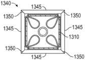
图11以横截面描绘了缝线捕获器的实施例;Figure 11 depicts an embodiment of a suture catcher in cross-section;
图12A和图12B描绘了将薄膜附接到支柱的实施例;Figures 12A and 12B depict an embodiment of attaching a membrane to a post;
图13A-13D描绘了将薄膜附接到支柱的实施例;13A-13D depict an embodiment of attaching a membrane to a post;
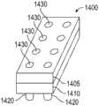
图14A和图14B描绘了用于将薄膜附接到支柱的实施例;14A and 14B depict an embodiment for attaching a membrane to a post;
图15A和图15B描绘了用于将薄膜附接到支柱的实施例;15A and 15B depict an embodiment for attaching a membrane to a post;
图16描绘了用于将薄膜附接到支柱的实施例的透视图;16 depicts a perspective view of an embodiment for attaching a membrane to a post;
图17描绘了用于管理薄膜松弛的实施例;Figure 17 depicts an embodiment for managing film relaxation;
图18A和图18B描绘了缝线输送装置手柄的实施例;18A and 18B depict an embodiment of a suture delivery device handle;
图19A和图19B描绘了缝线输送装置手柄的实施例;19A and 19B depict an embodiment of a suture delivery device handle;
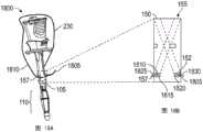
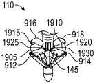
图20A-20C描绘了缝线捕获器的实施例;20A-20C depict an embodiment of a suture catcher;
图21A-21E描绘了多次使用的缝线捕获器的实施例;21A-21E depict an embodiment of a multiple-use suture catcher;
图22A-22D描绘了缝线传递器末端的实施例;22A-22D depict an embodiment of a suture passer tip;
图23A和图23B描绘了缝线输送装置的实施例;23A and 23B depict an embodiment of a suture delivery device;
图24A-24E描绘了缝线捕获器的实施例;24A-24E depict an embodiment of a suture catcher;
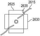
图25A和图25B描绘了缝线捕获器的实施例;25A and 25B depict an embodiment of a suture catcher;
图26描绘了缝线捕获器的实施例;以及Figure 26 depicts an embodiment of a suture catcher; and
图27描绘了缝线捕获器的实施例。Figure 27 depicts an embodiment of a suture catcher.
具体实施方式Detailed ways
首先,应当理解本公开不受限于具体示例的材料、架构、常规、方法或者结构,因为这些可能变化。因此,尽管在本公开的实践或实施例中能够使用与本文中所述的那些相似或等效的若干这样的选项,但是在本文中描述了优选的材料和方法。At the outset, it is to be understood that this disclosure is not limited to the materials, architecture, conventions, methods, or structures of the specific examples, as such may vary. Thus, although several such options similar or equivalent to those described herein can be used in the practice or embodiments of the present disclosure, the preferred materials and methods are described herein.
还应当理解,在本文中使用的术语仅用于描述本公开的具体实施例的目的,且不意欲为限制性的。It is also to be understood that the terminology used herein is for the purpose of describing specific embodiments of the present disclosure and is not intended to be limiting.
下文中结合附图陈述的详细描述预期为本公开的示例性实施例的描述,且不意欲表示本公开可在其中实践的唯一示例性实施例。贯穿该描述所使用的术语“示例性”意为“用作示例、例子或说明”,且不应必然解释为比其他示例性实施例优选或有利。详细描述包括特定细节,用于提供说明书的示例性实施例的透彻理解的目的。对于本领域技术人员将显而易见的是,说明书的示例性实施例可在没有这些特定细节的情况下实践。在一些例子中,公知结构和装置以框图形式示出,以便避免模糊在本文中呈现的示例性实施例的新颖性。The detailed description set forth below in connection with the appended drawings is intended to be a description of exemplary embodiments of the present disclosure, and is not intended to represent the only exemplary embodiments in which the present disclosure may be practiced. The term "exemplary" as used throughout this description means "serving as an example, instance, or illustration," and should not necessarily be construed as preferred or advantageous over other exemplary embodiments. The detailed description includes specific details for the purpose of providing a thorough understanding of the exemplary embodiments of the description. It will be apparent to those skilled in the art that the exemplary embodiments of the description may be practiced without these specific details. In some instances, well-known structures and devices are shown in block diagram form in order to avoid obscuring the novelty of the exemplary embodiments presented herein.
仅出于方便和清楚的目的,方向术语,诸如顶部、底部、左、右、上、下、在...之上、在上面、在下方、在...之下、后部、背部和前部,可关于附图使用。这些和相似的方向术语不应当解释为以任意方式限制本公开的范围。For convenience and clarity only, directional terms such as top, bottom, left, right, up, down, over, over, under, under, rear, back and Front, available in relation to the drawings. These and similar directional terms should not be construed to limit the scope of the present disclosure in any way.
除非以其他方式限定,否则在本文中使用的所有科技术语与本公开所属领域的普通技术人员通常所理解的意思具有相同的意思。例如,术语“缝合”包括利用柔性材料拉拢两个表面或边缘,以闭合穿刺、开口或者其他伤口,其中,缝线是一种材料,其可为合成的或者天然的,诸如聚合物、肠、金属线或其他合适的等效物。Unless otherwise defined, all technical and scientific terms used herein have the same meaning as commonly understood by one of ordinary skill in the art to which this disclosure belongs. For example, the term "suture" includes the use of a flexible material to draw together two surfaces or edges to close a puncture, opening, or other wound, wherein a suture is a material, which may be synthetic or natural, such as polymer, intestinal, Wire or other suitable equivalent.
如在该说明书和所附权利要求中使用的,单数形式“一”、“一个”和“所述”包括复数个指示物,除非该内容以其他方式清楚地指示。As used in this specification and the appended claims, the singular forms "a," "an," and "the" include plural referents unless the content clearly dictates otherwise.
本文中的实施例描述了缝线输送装置,其可插入到用于执行诸如腹腔镜手术的外科手术的相同开口中。缝线输送装置通过压缩周围组织减小了相对于开口倾斜、旋转或滑动的可能性,因此将装置稳定在开口内。因此稳定后,缝线输送装置能够通过将缝线可靠地引导到预定组织区域或层而改善组织咬合。缝线输送装置可用于定向一个或多个缝线传递器,其穿过输送装置的本体以刺穿穿刺口组织且在刺穿之后释放缝线。缝线输送装置捕捉缝线,且在抽出输送装置时,缝线端部通过开口拉回,以便缝线可被紧固且开口闭合。实施例易于使用,这对于组织闭合装置是重要的,其可以是漫长的令人疲惫的外科手术的最后步骤。Embodiments herein describe suture delivery devices that can be inserted into the same openings used to perform surgical procedures such as laparoscopic procedures. The suture delivery device reduces the likelihood of tilting, rotating or sliding relative to the opening by compressing the surrounding tissue, thus stabilizing the device within the opening. Thus stabilized, the suture delivery device can improve tissue occlusion by reliably guiding the suture to a predetermined tissue area or layer. The suture delivery device can be used to orient one or more suture passers through the body of the delivery device to pierce the puncture tissue and release the suture after piercing. The suture delivery device captures the suture, and when the delivery device is withdrawn, the suture ends are pulled back through the opening so that the suture can be secured and the opening closed. Embodiments are easy to use, which is important for tissue closure devices, which can be the last step in a long and exhausting surgical procedure.
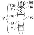
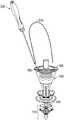
缝线输送装置(或“伤口闭合装置”或者“套管针伤口闭合装置”(TWC))大体具有两个部分:手柄100(图1A、图1B)和缝线传递器(图2A-2C)。图1A和图1B描绘了缝线输送装置手柄100的实施例的两个构造。在装置插入到开口中时,使用在图1A中的构造。在图1A中,手柄100处于未压缩构造。图1A描绘了手柄100,其带有轴105、捕获器110(包括捕获器元件112、114)、滑动器115、针道150、155和缝线离开狭缝160。轴105是配备有脊状轨道120的细长部署构件。滑动器115是压缩构件,其可沿着轴105朝远端端部135移动,且通过接合轨道120固定在适当位置。未示出的抗旋转隆起连同轨道120防止滑动器115相对于针道150、155旋转(图1B)。滑动器按钮125可用于接合或脱离轨道120。示出为闭合的捕获器110在展开时是反作用力构件,且可包括齿140,其可围绕缝线闭合且抓住缝线。示出为压低的控制按钮130移动控制杆145(图1B),其通过移动支柱165、170打开(或者展开)或闭合捕获器110。在捕获器110闭合的情况下,远端端部135、捕获器110和轴105可插入到外科手术开口中,直到捕获器110通过开口为止,在该点,捕获器110可如在图1B中所示展开。A suture delivery device (or "wound closure" or "trocar wound closure" (TWC)) generally has two parts: a handle 100 (Figures 1A, 1B) and a suture passer (Figures 2A-2C) . 1A and 1B depict two configurations of an embodiment of a suture
在图1B中,手柄100处于压缩构造,其中控制按钮130示出为被释放,控制杆145可见,捕获器110被展开,且滑动器115朝远端移动。为了展开捕获器110,释放控制按钮130,以朝近端(即,朝控制按钮130,或者在该视图中“向上”)移动控制杆145,从而导致支柱165、170展开捕获器110。为了朝近端或朝远端移动滑动器115,滑动器按钮125用于使滑动器115从轨道120脱离,且然后滑动器115可被移动。可选地,滑动器115可沿着轴105朝远端松脱,其中滑动器按钮125用于使滑动器115从轨道120脱离,且朝近端移动滑动器115(参见图7)。In Figure IB, handle 100 is in a compressed configuration with
在图1B中的构造可在滑动器115和捕获器110之间压缩组织。例如,腹壁的筋膜、肌肉和腹膜层可在滑动器115和捕获器110之间被压缩,其中腹膜最靠近捕获器110。如所示展开的,捕获器110将抵抗被牵拉通过在腹壁中的开口。因此,在该实施例中,捕获器110为反作用力构件。在其他实施例中,反作用力可通过缺乏缝线捕获能力的元件施加。类似地,在其他实施例中,缝线-捕获能力可通过缺乏反作用力能力的元件提供。The configuration in FIG. 1B can compress tissue between the
在这种构造中,在组织被压缩在滑动器115和捕获器110之间的情况下,手柄100相对于压缩的组织是稳定的,从而减小旋转、滑动或倾斜的可能性。此外,在手柄100稳定的情况下,针道150、155也相对于周围的组织(其为待缝合的组织)是稳定的。这提供缝线的最优放置,以及以可重复的方式部署缝线,这两者都用于确保适当的组织咬合以及最小化对操作人员所要求的技能量。In this configuration, with tissue compressed between the
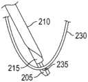
图2A-2C描绘了缝线传递器200的实施例。缝线传递器200用于抓住缝线端部以及传递缝线通过针道,例如,针道150,以定位缝线,以便其可被捕获器110捕获。缝线传递器200包括在远端端部处的钩子205、针管210、轴215、触发器220和针按钮225。钩子205在轴215的远端端部处。针管210具有在远端端部处的点且可相对于轴215移动,以覆盖或揭露钩子205。钩子205被构造成接受缝线230(参见图2B)以及当通过针管210覆盖时保留缝线(参见图2C)。钩子205可具有钝的末端-在装载缝线时不是必要的点。钩子205还可具有斜坡235,其在揭露钩子205时允许缝线滑落。在图2A中,针按钮225被示出为延伸的(未被按压)且钩子205被示出为未被揭露。针按钮225在被按压时可使针管210在钩子205上延伸,以保留缝线。触发器220在被按压时可导致针管揭露钩子205以释放缝线。针管210、轴215、钩子205、和触发器220被构造成配合在针道150、155内,以输送缝线及在相对于展开的捕获器110的期望地点中释放缝线。2A-2C depict an embodiment of a
图2B和图2C大体描绘了缝线传递器200的装载。缝线传递器200具有通过针按钮225和触发器220控制的两种状态。在初始“闲置(off)”状态中,轴215和钩子205从针管210伸出。钩子205用于以这种构造接收缝线。也就是说,缝线230可定位成被钩子205抓住。为了转变到“使用(on)”状态,用户按压针按钮225,这导致针管210延伸以覆盖缝线230和钩子205。因此,轴215、钩子205、和针管210协作以保留或抓住缝线230。为了返回到“闲置”状态,触发器220可通过沿近端方向按压其而被激活。按压触发器220可因此释放缝线230。2B and 2C generally depict the loading of the
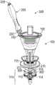
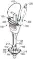
图3描绘了缝线输送装置300。在图3中,缝线传递器200插入到手柄100的针道150中。手柄100处于压缩构造中,其中,捕获器100被展开且滑动器115朝远端移动。针按钮225示出为被压低,其中,针管210覆盖钩子205(未示出)。针管210的远端末端靠近薄膜302。薄膜302在捕获器元件114和314之间延伸。薄膜305在捕获器元件112和312之间延伸。FIG. 3 depicts a
如在图3中所示,针道150使缝线传递器200定向成指向在展开的捕获器110的捕获器元件114和314之间的区域。在该实施例中,捕获器110被设置成在该区域带有薄膜302。添加薄膜302以改善捕获器110捕获缝线的能力。如果缝线传递器200进一步插入到针道150中,则针管210的尖点将带着缝线(未示出)一起刺穿薄膜302。进一步的插入将导致触发器220触及针道150的开口。更进一步的插入将导致触发器220致动并导致针管210收回,从而暴露钩子205且释放缝线(未示出)。此时,可从针道150抽出缝线传递器200。从针道抽出缝线传递器200还将其从薄膜302中抽出。但是已经从钩子205释放的缝线将保留在薄膜302内。然后,如果捕获器110然后收回,则薄膜302也收回,从而使缝线与其一起通过捕获器元件114、314被抓住。这关于图9A和图9B进一步被描绘。As shown in FIG. 3 ,
图4A-4C描绘了提供自动缝线释放的手柄100的实施例。当单个缝线的两个端部被输送到外科手术开口中且保留在缝线输送装置的远端端部处时,缝线靠近近端端部的部分形成环。在装置取回期间,环可变得与装置缠在一起。现有的闭合装置允许操作人员将缝线与装置手动分开。图4A-4C的实施例使用内部缝线脱离狭槽400,其促进缝线415的自动释放。缝线脱离狭槽400在针道整个长度上连接针道150、155,从而提供用于缝线415穿过手柄100且离开缝线离开狭槽160的狭槽。在图4A中,缝线传递器200被插入针道155中,且从轴105延伸从而暴露针管210。针管210在刺穿薄膜305之后被示出。缝线415的缝线末端410被示出为也穿过薄膜305,其已经由缝线传递器200的末端携带通过。控制按钮130示出为是延伸的。因此,针管210不覆盖钩子205,且缝线端部410从缝线传递器200释放(不过针末端在图4A中通过薄膜305遮蔽)。针道150示出缝线415在缝线端部405已经穿过薄膜302之后被释放,且缝线传递器200被抽出。如在图4A中所示,缝线端部405、410二者都通过薄膜302、305被保留。从缝线端部405,缝线415穿过并离开针道150,在手柄100上成环,且伴随缝线传递器200,进入针道155。在图4A-4C中,未示出滑动器115,以更清楚地解释内部缝线脱离路径。4A-4C depict an embodiment of a
在图4B中,缝线传递器200已经从针道155抽出,且捕获器110已经收回,从而抓住缝线端部405、410。手柄100可以以这种构造从外科手术开口中抽出,从而随其牵拉缝线端部405和410。缝线415在针道出口152和捕获器110之间形成环。缝线415还在针道出口157和捕获器110之间形成环。这些环表示缝线415的已经穿过待缝合的组织的部分。因此,当手柄100从外科手术开口移除,从而随其牵拉缝线端部410、415时,通过组织成环的缝线415的部分将缝线415的剩余部分向下牵拉通过缝线脱离狭槽400(如图所示,虚线)。在图4C中,缝线415已经完全穿过缝线脱离狭槽400且离开缝线离开狭槽160。In FIG. 4B , the
因此,参考图1-4,缝线输送装置300的手柄100的实施例可包括针道元件,例如,针道150、155,以及缝线保留元件,例如,捕获器110。针道元件可从手柄100的近端端部朝远端端部延伸,且可包括自动缝线释放机构,例如,缝线脱离狭槽400。缝线保留元件可安置在手柄100的远端端部处或其附近。缝线输送装置还可具有压缩元件,例如,滑动器115。Thus, with reference to FIGS. 1-4 , embodiments of
针道元件可提供用于针(例如,缝线传递器200)插入通过手柄(例如,手柄100)的限定轨道,其靠近近端端部开始且靠近远端端部离开。例如,在手柄插入到外科手术开口中的情况下,针可在皮肤上方进入针道元件(例如,针道150)的近端端部,行进通过装置中的针道,且在远端端部处离开,以相对于手柄在限定位置和角度处穿透组织层(诸如筋膜、肌肉和腹膜)。针轨道可通过手柄在入口和出口之间完全地封闭。针道元件可与自动缝线释放机构(参考图4A-4C被描绘)联接,借此,在手柄从外科手术开口抽出时,缝线环(或者缝线的主要部分,排除缝线端部)不被保留在装置的远端端部处且可在没有用户介入的情况下从针道滑出。The needle track element may provide a defined track for insertion of a needle (eg, suture passer 200 ) through a handle (eg, handle 100 ) that begins near the proximal end and exits near the distal end. For example, with the handle inserted into a surgical opening, the needle may enter the proximal end of the needle track element (eg, needle track 150 ) above the skin, travel through the needle track in the device, and at the distal end to penetrate tissue layers (such as fascia, muscle, and peritoneum) at defined locations and angles relative to the handle. The needle track can be completely closed by the handle between the inlet and the outlet. The needle track element may be coupled with an automatic suture release mechanism (depicted with reference to Figures 4A-4C) whereby the suture loop (or the main portion of the suture, excluding the suture ends) is withdrawn from the surgical opening as the handle is withdrawn from the surgical opening. It is not retained at the distal end of the device and can be slid out of the needle track without user intervention.
缝线保留元件(例如,捕获器110)可包括骨架(例如,捕获器元件112、114、312、314)和缝线捕捉表面(一个或复数个)(例如,薄膜302、305)或者仅骨架。缝线保留元件可设有特征(例如,齿140),以改进其在缝线上的抓持。缝线保留元件骨架可具有多个支柱,且可具有各种几何形状(例如,平的、灯笼形、帆鳍状(molly)、伞状等)。缝线保留元件骨架可限定目标区域,且可提供对于压缩元件的压缩力的反作用力,从而将组织夹置在其间。该反作用力可抵靠例如腹膜。在针插入期间,缝线保留元件还可向可选缝线捕捉表面提供支撑。缝线保留元件可在低姿态(low profile)或收回状态中插入通过组织开口,且在穿过组织层到预期位置(其可例如为腹腔内部)之后展开到其张开状态。缝线捕捉表面可联接到骨架的支柱,且可在装置插入期间以及在装置抽出期间处于折叠构造。The suture retention element (eg, catcher 110 ) may include a skeleton (eg,
携带缝线的针(例如,缝线传递器200)可被引入到针道元件(例如,针道150)中,被引导穿过组织层(例如,经过腹膜),且插入到捕获器中(例如,定位在捕获器元件112、312之间,或者插入到薄膜305中)。针的远端末端的设计可允许缝线从针脱离(例如,钩子205可具有斜坡235,其允许缝线230滑落,而不是真实的“钩子”)。在一些实施例中,当针插入到预期位置之后,可触发针以从其末端释放缝线。A suture-carrying needle (eg, suture passer 200 ) can be introduced into a needle track element (eg, needle track 150 ), guided through tissue layers (eg, through the peritoneum), and inserted into a trap (eg, through the peritoneum). For example, positioned between the
在实施例中,针末端设计(例如,斜坡235)可允许缝线脱离针。在带有捕捉表面(例如,薄膜302、305)的实施例中,表面本身可具有通过表面增强对缝线的捕捉和保留的性质或者设计,这辅助缝线从针脱离。In an embodiment, the needle tip design (eg, ramp 235) may allow the suture to escape from the needle. In embodiments with capture surfaces (eg,
在将捕捉的缝线端部保留在装置的远端端部处(例如,在捕获器中)时,装置可从外科手术开口(例如,套管针伤口)中抽出。The device may be withdrawn from a surgical opening (eg, a trocar wound) while retaining the captured suture ends at the distal end of the device (eg, in a trap).
在实施例中,在捕获器通过组织层的插入和抽出期间,薄膜基本上通过捕获器骨架封闭。在实施例中,缝线端部可被捕捉在薄膜中并且保持在闭合的捕获器骨架的支柱之间。在其中缝线保留元件包括骨架的实施例中,在装置取回期间缝线端部可通过在闭合骨架的支柱之间的机械夹持被保留。In embodiments, the membrane is substantially enclosed by the trap backbone during insertion and extraction of the trap through the tissue layer. In an embodiment, the suture ends may be captured in the membrane and held between the struts of the closed capture frame. In embodiments in which the suture retention element comprises a skeleton, the suture ends may be retained by mechanical clamping between the struts of the closed skeleton during device retrieval.
缝线输送装置还可具有压缩元件,例如,滑动器115,其能沿着装置轴移动以适应不同的身体结构。压缩元件可放置在下述位置中,其夹置组织抵靠反作用力构件(例如,捕获器110)。例如,组织可为腹壁的层,反作用力构件可抵靠腹膜定位在腹腔中,且压缩元件可抵靠皮肤的表面。压缩元件因此稳定组织,同时适应不同的身体结构。在一些实施例中,压缩元件可链接到反作用力构件展开机构,以便压缩元件的运动导致反作用力构件展开和收回。The suture delivery device may also have compression elements, eg, a
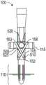
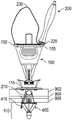
图5A和图5B示出带有可伸缩针道153、158的手柄100的实施例的横截面。在图5A中,手柄100处于未压缩构造,其中,滑动器115朝近端延伸,远离捕获器110。出于简单起见,且因为可伸缩针道153、158相似,所以将仅描述可伸缩针道153。可伸缩针道153包括一对管505、510,其被构造成管510在管505内伸缩。在实施例中(未示出),管505在管510内移动,以便缝线传递器在插入时将避免撞击管510的端部。在图5A和图5B中,管505在非-可伸缩端部处锚固到滑动器115。管510在非-可伸缩端部处锚固到轴105。锚固附接件允许管和锚固点之间的有角度的运动。在图5B中,手柄100处于压缩的构造,其中,滑动器115朝远端移动朝着捕获器110。由于该运动,可伸缩针道153、158长度已经缩短,且改变其离开手柄100时的角度。但是,可伸缩针道153、158仍然定向成引导缝线传递器朝着捕获器110。在滑动器115从未压缩到压缩构造的运动中,可伸缩针道153已经在轴105内扫出一定体积,其通过上部限制520、下部限制525和针道出口12定界。在该实施例中,手柄100、轴105和滑动器115被构造成允许可伸缩针道153、158的这种运动。5A and 5B show cross sections of an embodiment of the
在使用实施例的方法中,手柄100最初处于未压缩和收回构造。在第一步骤中,手柄100被插入到套管针伤口中。在下一步骤中,按压控制按钮130以打开捕获器110。在下一步骤中,向上牵拉手柄100抵靠组织,直到捕获器110与腹膜接触为止。在下一步骤中,向下推滑动器115,以夹置腹壁抵靠捕获器110。然后手柄被稳定在待缝合的组织内。在下一步骤中,缝线230的一端被装载到钩子205上且按压针按钮225。在下一步骤中,缝线传递器200被插入到针道内且激活触发器220,从而释放缝线230。在下一步骤中,从手柄100抽出缝线传递器200。在下一步骤中,缝线230的第二端(或者不同缝线的端部)被装载到钩子205上,且在不同的针道中重复先前两个缝线-穿过步骤。现在可抽出手柄100,从而根据如下步骤随其带走缝线端部。在下一步骤中,按压控制按钮130以利用捕获器110捕捉缝线端部(缝线端部可还已经通过可选的薄膜302、305保留)。在下一步骤中,从外科手术开口中抽出手柄100,随其带着缝线端部。缝线端部然后从手柄100移除并打结。In the method of using an embodiment, the
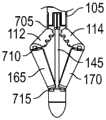
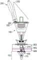
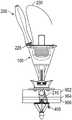
图6A-6C分别描绘了处于收回、部分展开和完全展开构造的缝线捕获器110的实施例。在图6A中,缝线捕获器110具有铰接接头705、710、715、支柱165、170和捕获器元件112、114。接头705、710、715可为机械的、或活动铰接件、或者组合。在图6B中,捕获器110已经通过使用控制杆145推动支柱165、170抵靠捕获器元件112、114被张开到部分展开状态。捕获器元件312、314已经类似地展开。在图6C中,捕获器110已经使用控制杆145完全地展开。图6C还示出附接到捕获器元件112、114的可选的薄膜302、305。控制按钮130(图1和图3)可连接到控制杆145,且用于激活控制杆145。6A-6C depict embodiments of the
图7以横截面描绘手柄100的实施例的区段。在图7的实施例中,滑动器115可使用棘轮805和齿条810朝远端方向而不是朝近端方向容易地移动。因此,滑动器115可朝着压缩构造而不是朝未压缩构造容易地移动。在实施例中,推动滑动器按钮125释放棘轮805,从而允许滑动器115朝近端移动。齿条810可包括下部限制(未示出),其防止滑动器沿压缩方向移动得过远。在实施例中,在滑动器115和轴105之间使用摩擦衬垫(未示出)。摩擦衬垫的形状被设计为沿两个方向调整推动摩擦。FIG. 7 depicts a section of an embodiment of
图8A-8G描绘了在部署缝线的各个阶段中的实施例。图8A是插入到针道150中的装载的缝线传递器200的透视图。在图8A中,捕获器110处于展开构造。抓持缝线端部405的针管210已经离开针道150,但是还未穿透薄膜302。在图8B中,缝线传递器200已经进一步插入到针道150中,以便针管210已经穿透薄膜302(未示出),从而也带着缝线端部405通过薄膜302。在图8B中,针管210示出为刺穿三层组织902、904、906。因此,最后,缝线230的咬合将包括那些层。在图8C中,缝线传递器200已经更进一步插入到针道150中,从而导致触发器220压低,其如参考图2A-2C所描述的,将针管210重设置为“闲置”且从缝线传递器200释放缝线230。图8D描绘了来自图8C的装置的近视图。在图8D中,针管210和缝线端部405已经穿透薄膜302。可看出缝线端部405离开钩子205和针管210。在图8E中,缝线传递器200已经从针道150中抽出。缝线端部405已经被保留-通过薄膜302的保留挤压性质保持。图8F描绘了利用缝线端部410、针道155和薄膜305(未示出)重复的过程。图8F还描绘了缝线利用各自穿过组织层902、904、906的缝线端部405、410的咬合。以及图8G描绘了在缝线传递器200已经将缝线端部405、410分别部署到薄膜302、305中且已被抽出之后的手柄100。8A-8G depict embodiments in various stages of deploying a suture. FIG. 8A is a perspective view of the loaded
图9A和图9B描绘了处于捕捉缝线端部的不同阶段的手柄100。在缝线端部405、410被部署到薄膜302、305上(如在图8G中)之后,按压控制按钮130,从而朝远端移动控制杆145以闭合捕获器110。图9A描绘了大约在捕捉缝线端部的过程的中途的手柄100。当压低控制按钮130时,薄膜302、305分别折叠在捕获器元件114、314(图3)和112、312(图3)之间,且随其携带缝线端部405、410。图9B描绘了处于收回构造的捕获器110。控制按钮130已经完全被压低。在这种构造中,捕获器110不再提供对滑动器115的压缩力的反作用力,滑动器115仍然处于压缩位置。也就是说,捕获器110不再对组织层902、904、906呈现平坦表面,且可容易地抽出。在完全收回位置,元件114、314和112、312夹持相应缝线端部405、410。可选的齿140,其也可在捕获器元件112、312和114、314之间(参见图6C、图8D),以改善对缝线端部405、410的保持。9A and 9B depict the
图10A和图10B描绘了在捕获器110已经完全收回之后,自动地释放缝线的手柄100的实施例。在图10A中,缝线230已经被部署到例如腹壁的层902、904、906上,其中,缝线端部405、410被捕获器110捕捉在手柄100上。手柄100已经从外科手术开口1100被牵拉,手柄100携带着缝线端部405、410且将更多的缝线230牵拉到外科手术开口1100中并且通过组织层902、904、906。这导致缝线230的环进入缝线脱离狭槽400(参见图4A-C)。在图10B中,对手柄110的持续牵拉已经导致缝线230的剩余部分穿过缝线脱离狭槽400且离开缝线离开狭槽160。10A and 10B depict an embodiment of a
使用实施例以闭合伤口的方法始于缝线输送装置手柄处于未压缩和收回构造且缝线传递器与手柄分离。在步骤1中,一只手将套管针从伤口移除。在步骤2中,另一只手将手柄插入到套管针伤口中直到捕获器在腹腔镜影像中完全可见为止。在步骤3中,一根手指按压控制按钮以在使用腹腔镜影像的视觉指导下打开捕获器。在步骤4中,一只手保持手柄且另一只手朝患者推动滑动器直到待缝合的组织牢固地夹置在滑动器和捕获器之间为止。腹腔镜影像可用于示出捕获器是否与腹膜壁接触。在步骤5中,一只手保持缝线传递器本体,且另一只手将缝线的一端放到缝线传递器的钩子中。手指然后按压针按钮以装载缝线传递器。在步骤6中,再次在腹腔镜影像的视觉指导下,一只手保持手柄且另一只手将缝线传递器插入通过针道直到致动触发器为止,从而将缝线释放(或者部署)在捕获器上。在步骤7中,利用缝线的另一端和另一个针道重复步骤5和6。在步骤8中,一根手指按压控制按钮以在视觉指导下捕捉缝线端部。在步骤9中,一只手从伤口牵拉手柄,且从其取得两个缝线端部。A method of closing a wound using an embodiment begins with a suture delivery device handle in an uncompressed and retracted configuration with a suture passer separated from the handle. In
图11在平面视图且在横截面中描绘了作为打开和闭合缝线捕获器结构的部分的缝线捕获器结构的支柱的实施例。缝线捕获器1105可包含若干支柱1110。每一个支柱1110可具有到近端接头1117(上部铰接件)的近端连接部分1115、上部支柱1120、中间铰接件1125、下部支柱1130、远端(或下部)铰接件1135以及到远端铰接件1135的远端连接部分1140。铰接件可为活动铰接件、机械铰接件或金属线/板簧铰接件。支柱可由金属(即不锈钢)、塑料(即聚丙烯、聚碳酸酯、聚亚安酯、尼龙、或聚乙烯)或任何其他适当材料制成。多个支柱可在近端接头处以及在远端接头处链接以形成捕获器。控制杆1145可联接到捕获器的远端连接部分1140且延伸到缝线输送装置的近端端部。在一个实施例中,控制杆1145的运动驱动远端连接部分1140的上下运动,从而导致缝线捕获器的打开(远端接头向上,或“展开”)或闭合(远端接头向下,或“收回”)。在替代实施例中,捕获器展开机构可通过控制近端连接部分1115被驱动。在实施例中,在处于展开构造时,捕获器1105用作对于组织-压缩力的反作用力构件。11 depicts, in plan view and in cross-section, an embodiment of a strut of a suture catcher structure as part of opening and closing the suture catcher structure. The
下部和上部支柱的长度可基于捕获器1105的目标区域的期望大小或者基于在上部和下部支柱之间形成的期望角度或者两者被选择。支柱的形状可为矩形或梯形。相比矩形形状,梯形形状的优势在于梯形形状提供额外的薄膜压紧空间。支柱的外部表面(在收回构造中可见的表面)具有许多可能的变型,包括平坦的、平坦的且带有弯曲边缘,或者弯曲的。带有弯曲表面的设计可导致缝线输送装置带有更加防止创伤的外部轮廓,因为那里会存在更少的锋利边缘。也就是说,在各种实施例中,支柱部件(包括伸出的和匹配的特征)可以是平坦的或者可以是弯曲的,以创造更圆滑的外部轮廓,参见例如,图13C。The lengths of the lower and upper struts may be selected based on the desired size of the target area of the
图12A和图12B示出将薄膜1200附接到支柱1205的实施例。薄膜1200可由诸如聚亚安酯、PVC、聚丙烯或将不太抵抗被刺穿或折叠的其他柔性材料制成。为了在装置抽出期间将缝线更可靠地保留在支柱之间,捕获器应当闭合,以便邻近的支柱(或者用于紧固缝线的特征,诸如齿)能够以所设计的方式接合。如果薄膜折叠且压紧成不妨碍捕获器骨架闭合的轮廓,则更可能进行捕获器的适当闭合。但是捕获器薄膜可能不是以任意具体方向或构造自然地折叠或者压紧。此外,可在其中压紧薄膜的空间是通过支柱在其收缩时封闭的空间,并且该空间是受限的。而且,带有变化的厚度和刚度的薄膜具有不同的折叠行为。已经发现相对于支柱的薄膜附接位置影响其折叠行为。因此,在实施例中,捕获器的支柱或骨架可设计为引导薄膜以期望的方式折叠,例如,朝着控制杆1245径向朝内(图12B)。12A and 12B illustrate an embodiment of attaching
薄膜可通过各种方法(例如,粘合剂、机械附接等)联接到骨架支柱。薄膜附接位置可完全地延伸到支柱的边缘,或者可附接在从支柱的侧向边缘的凹入位置中。为了促进在捕获器闭合后时通过支柱完全封闭薄膜,如在图12A和图12B中所示,薄膜1200可附接在从侧向边缘的凹入位置1210中。薄膜1200通常具有最小的曲率和半径。因此,附接从支柱1205的边缘凹入的薄膜1200允许薄膜1200折叠在通过支柱限定的空间内,如通过折叠1215所示。这帮助防止薄膜1200聚集在支柱1205之间,且降低其夹持在一起且紧固缝线的能力。The membrane can be coupled to the skeletal struts by various methods (eg, adhesives, mechanical attachment, etc.). The membrane attachment locations may extend completely to the edge of the strut, or may be attached in recessed locations from the lateral edges of the strut. To facilitate complete closure of the membrane by the struts when the trap is closed, as shown in Figures 12A and 12B,
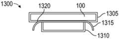
图13A-13D描绘了用于将薄膜附接到支柱的另外的实施例。在图13A中,支柱1300具有两件式结构,包括外部(或顶部)支柱部件1305和内部(或底部)支柱部件1310,其组合以夹置薄膜1315。外部支柱部件可比内部支柱部件更宽,且薄膜附接边缘1320可从外部部件1305的边缘凹入。在外部和内部支柱部件宽度之间的差异通过夹置薄膜提供薄膜附接支撑,且通过允许薄膜附接边缘1320从支柱1305的边缘凹入而促进薄膜折叠。在图13B中,薄膜引导特征1325可在支柱1305和薄膜1315之间使用,以帮助朝内推动薄膜。引导特征1325可为支柱1305的一部分、或薄膜1315、或单独的扩展部件。引导特征1325可例如为金属杆。引导特征1325从支柱的表面伸出,以增大或开始薄膜1315的折叠。因此,代替采取与支柱1305更平行的路径,薄膜1315直接朝内弯曲以帮助实现预期的薄膜折叠。各种形状和大小的伸出特征可用于按照预期形成不同的薄膜弯曲模式。13A-13D depict additional embodiments for attaching membranes to struts. In FIG. 13A , the
在图13C中,外部支柱部件1330可具有边缘,其略微朝内弯曲以在捕获器闭合时帮助促进薄膜1315朝内折叠并且远离外部支柱边缘。图13D描绘了在闭合构造中具有2件支柱设计的捕获器的实施例。闭合的捕获器1340也具有外部支柱部件1345,其带有有角度的边缘1350,这增大了在外部支柱部件1345之间的接触表面。In Figure 13C, the
大体上,可使用各种方法,诸如粘合剂、机械附接、融合、喷射模塑或任何其他合适的方式将薄膜联接到捕获器支柱或骨架。In general, the membrane may be coupled to the trap strut or backbone using various methods such as adhesives, mechanical attachment, fusion, injection molding, or any other suitable means.
图14A和图14B描绘了用于机械地附接薄膜的实施例。在实施例中,支柱1400可具有带有外部/顶部支柱部件1405和内部/底部支柱部件1410的两件式结构,其夹置薄膜1415。薄膜1415优选地是柔性的,且可通过机械方法被紧固,诸如夹住或扣住。在该实施例中,外部支柱部件1405和内部支柱部件1410具有互锁特征1420,其组装在一起以紧固薄膜1415。互锁特征1420包括伸出特征和对应孔洞,其配合以将薄膜1415固定在支柱1405、1410之间。薄膜1415伸长且围绕伸出特征1420成型。位置1430指示特征1420的可能模式。替代地,薄膜1415可具有对应于特征1420冲成的孔洞,以便薄膜1415不伸长以符合特征1420。14A and 14B depict an embodiment for mechanically attaching a thin film. In an embodiment, the
图15A和图15B描绘了用于机械地附接薄膜的实施例。在图15A中,薄膜1505具有孔洞,其允许伸出特征1520的通过。替代地,伸出特征可设计为在支柱部件互锁过程期间刺穿通过薄膜1505。支柱可包含多个伸出和匹配的特征,以形成期望的紧固模式。15A and 15B depict an embodiment for mechanically attaching a film. In FIG. 15A, the
到支柱的薄膜附接可通过由互锁部件产生的机械力唯一地提供。替代地,还可使用粘合剂以提供额外的薄膜附接力。在其中伸出特征是塑料的且穿过在薄膜中的孔洞的实施例中,伸出特征能够熔化或焊接到另一个支柱部件,以提供互锁力。额外地,薄膜还可被热熔合到支柱部件中的一个或两个。Membrane attachment to the struts can be provided exclusively by mechanical force created by the interlocking components. Alternatively, adhesives may also be used to provide additional film attachment. In embodiments where the protruding features are plastic and pass through holes in the film, the protruding features can be melted or welded to another strut member to provide an interlocking force. Additionally, the film may also be heat fused to one or both of the strut members.
在抵抗蠕变方面金属相比塑料具有优势,且其更有效地用作张紧保持元件。在图15A的实施例的替代中,薄膜1505可在伸出特征1520上伸展,同时应用具有“金属夹”形式的匹配特征的支柱部件以将薄膜1505夹置到伸出特征1520。金属夹部分可通过冲压或通过任何其他适当的方法形成。Metals have advantages over plastics in terms of resistance to creep, and they function more effectively as tension-retaining elements. In an alternative to the embodiment of FIG. 15A , the
图15B描绘了额外于图15A的实施例的实施例。匹配特征具有薄金属部分的形式-带有狭槽1530的滑动-锁1525。狭槽1530定大小成滑动到伸出特征1520的颈部上。在这种变型中,薄膜已经被冲出孔洞以让伸出特征进入。滑动-锁1525可冲压成型或激光切割或者通过任何其他适当的方法制成。Figure 15B depicts an embodiment in addition to the embodiment of Figure 15A. The mating feature is in the form of a thin metal portion - a slide-
图16描绘了用于机械地附接薄膜(通过使薄膜穿透通过支柱)的实施例。可在缝线捕获器支柱1610中创建小的狭缝1605,且可使薄膜1615穿透通过这些开口。开口的大小、长度和几何形状可被优化以控制薄膜1615到支柱1610的附接。薄膜1615可从支柱1610的内侧插入通过第一狭缝1605,横越支柱1610的外侧,且然后插入通过第二狭缝1605以在支柱1610的内侧上重新出现。Figure 16 depicts an embodiment for mechanically attaching the membrane by penetrating the membrane through the struts.
额外地,粘合剂或其他方法也可用作附属方法以增大薄膜-支柱固定力。狭缝1605还服务于引导或控制薄膜1615离开支柱1610的角度的目的。狭缝1605,由于其远离侧向边缘定位,导致薄膜1615在支柱的内部上从侧向边缘凹入一些距离出现。薄膜1615因此更不可能干涉支柱闭合,因为其具有空间以径向朝内转向且已经通过狭缝1605在该方向上被引导。Additionally, adhesives or other methods may also be used as adjunct methods to increase the film-to-strut fixation force. The
在替代实施例中,狭缝1605可延伸到支柱1605的一端,从而产生开口用于薄膜1615滑动到支柱1610中且通过支柱1610保留(类似于纸夹)。打开的边缘可在外部径向边缘上或在接近装置轴的内部边缘上。In an alternate embodiment, slit 1605 may extend to one end of
在两个支柱之间伸展的薄膜具有沿着未支撑的边缘松弛的倾向。在实施例中,薄膜可松弛,尤其在它们径向延伸超出在两个支柱端部之间的引导线的情况下。在这种区段中,薄膜不具有来自支柱的足够支撑,且自身可能不够坚硬以在被针或缝线传递器接触时抵抗弯曲。这种弯曲可减少用于缝线捕捉的有效目标区域,因为针可滑动经过弯曲薄膜,而不是刺穿其。实施例涉及管理薄膜可松弛或弯曲的程度,许多通过改善薄膜拉紧度。The membrane stretched between the two struts has a tendency to relax along the unsupported edge. In embodiments, the membranes may relax, especially if they extend radially beyond the guide wire between the ends of the two struts. In such sections, the membrane does not have sufficient support from the struts, and may not be rigid enough by itself to resist bending when contacted by a needle or suture passer. This curvature can reduce the effective target area for suture capture because the needle can slide through the curved membrane instead of piercing it. Examples relate to managing the degree to which a film can relax or bend, many by improving film tension.
图17描绘了用于管理薄膜可松弛或弯曲的程度的捕获器实施例。在图17中,薄膜1705具有直线边缘1710,其遵循在两个邻近的打开的支柱1715的外部径向边缘之间的线。相比其中薄膜材料延伸超出在支柱端部之间的线的形状(例如,薄膜带有延伸的弧形外部边缘),薄膜1705可更有效地捕捉缝线。直线形薄膜1705消除了未通过支柱1715良好支撑的薄膜区域,并因此减小在针接触后薄膜1705弯曲的可能性。因此,薄膜1705最大化有效的缝线捕捉区域。Figure 17 depicts an embodiment of a trap for managing the degree to which the membrane can relax or bend. In FIG. 17 , the
在替代实施例中,在其中不预期缝线捕捉,即不引导针道处的支柱之间,薄膜可为任何形状,或不存在。In alternate embodiments, between struts where suture capture is not expected, ie, where the needle track is not guided, the membrane may be of any shape, or absent.
在实施例中,薄膜1705的边缘可利用张紧元件1720强化,张紧元件1720改善了薄膜拉紧度。在一个实施例中,张紧元件1720可为联接到薄膜的边缘的细绳或其他纤维,其中,其端部附接到捕获器支柱,非常类似于围绕风筝的周边的细绳。例如,张紧元件1720可为在薄膜的边缘处熔合的凯夫拉尔纤维。纤维可伸展以在支柱端部之间的纤维区段中产生张力,且因此向薄膜的外部边缘提供支撑。用于张紧纤维的机构可以是捕获器支柱的展开。在捕获器支柱已经展开之后,用于张紧纤维的替代或额外机构可导致支柱径向朝外延伸。In an embodiment, the edges of the
纤维可通过不同的方法联接到薄膜边缘。一个方法是将纤维胶合到薄膜的边缘。另一种方法是折叠薄膜边缘以形成袋部来容纳纤维。又另一方法是熔合薄膜层连同嵌入在层之间的纤维。Fibers can be attached to the edges of the film by different methods. One method is to glue the fibers to the edges of the film. Another method is to fold the edges of the film to form pockets to accommodate the fibers. Yet another approach is to fuse the film layers together with fibers embedded between the layers.
张紧元件相比薄膜可更柔韧,以便张紧元件不消极地影响薄膜压紧。在实施例中,张紧元件本身可具有默认的弯曲,其帮助薄膜的折叠。张紧元件的横截面可具有任何期望的形状。The tensioning element can be more flexible than the film so that the tensioning element does not negatively affect the film compression. In an embodiment, the tensioning element itself may have a default bend that aids in the folding of the membrane. The cross-section of the tensioning element can have any desired shape.
图18A和图18B描绘了缝线输送装置手柄1800的实施例。在实施例中,在手柄1800插入到外科手术开口中之前,缝线端部1805、1810可装载到手柄1800上。在图18A中,缝线端部1805、1810已经在针道150、155的远端开口152、157处装载到手柄1800上。图18B描绘了装载缝线的摩擦方法。在图18B中,狭槽1815、1820被构造成通过例如压配合或其他楔固作用保留缝线端部1805、1810。在替代实施例中,添加柔性保留瓣部1825、1830以进一步保留缝线端部1805、1810。瓣部1825、1830可例如为橡胶或金属,取决于所期望的保留力。而且,手柄1800可具有在工厂组装过程期间装载的缝线端部1805、1810。18A and 18B depict an embodiment of a suture
图19A和图19B描绘了使用缝线盒装载缝线的实施例。在图19A中,盒1905储存一根缝线1910且具有提供接近缝线端部1915、1920的两个近入端口。在图19B中,手柄1900具有盒插入端口1925,其被构造成接收缝线盒1905且将暴露的缝线端部1915、1920在手柄1900内部定位在针道150、155内,用于在部署缝线的准备中最终装载到缝线传递器上。Figures 19A and 19B depict an embodiment of using a suture cartridge to load sutures. In FIG. 19A, the
在实施例中,滑动器115是弹簧-加载的以在按压控制按钮130时压缩待缝合的组织。因此,在实施例中,按压控制按钮130可导致两个动作。第一,可展开捕获器110,且第二,可推动滑动器115向远端-朝着捕获器115移动。这些动作可利用弹簧实现,弹簧在滑动器远离捕获器110朝近端移动时被加载。弹簧可具有触发器,其通过按钮行程的最终阶段被致动,以便按压控制按钮130首先打开捕获器110,且当按压控制按钮130任意更多量时,触发器致动以释放弹簧,其然后推动滑动器115抵靠皮肤,从而将组织夹置在滑动器115和捕获器110之间。In an embodiment, the
图20A-20C描绘了一种实施例,其中,翼部是捕获器支柱的柔性区段,且帮助捕捉缝线。图20A描绘了支柱912、914、916、918,其带有在尺寸和刚度方面类似于支柱112、114、312、314(图3)的区段。支柱912、914、916、918具有柔性翼部1905、1910、1915、1920。图20B描绘了在捕获器110收回时折叠在捕获器110内的柔性翼部1905、1910。在捕获器110展开时,翼部1905、1910、1915、1920打开到其预期位置,且翼部对912、916和914、918打开并叠置,呈现用于缝线的目标区域,如在图20A中那样。在实施例中,通过叠置翼部对呈现的目标区域是类似于通过薄膜302、305(图3)呈现的平面的平面,然而,1905、1910、1915、1920不依赖于用于支撑的张力,并且因此,其可被构造成延伸超出通过支柱912、914、916、918限定的区域。翼部1905、1910、1915、1920可通过被刺穿帮助捕捉缝线端部,类似于薄膜302、305,或者其可通过允许缝线传递器200穿过在翼部对之间的接缝1925、1930来捕捉缝线。一旦缝线传递器200穿过接缝1925、1930,释放缝线且抽出,翼部对1905、1915或1910、1920就围绕部署的缝线闭合并捕捉该部署的缝线。在捕获器110收回(图20C)时,捕捉的缝线端部可然后通过翼部对被拉入且通过支柱对912、916或914、918被更牢固地抓持。Figures 20A-20C depict an embodiment in which the wings are flexible sections of the capture struts and help capture the suture. 20A depicts
图21A-21E描绘了通过改变穿透捕获器薄膜的地点来允许捕获器薄膜的多次使用的实施例。通常,针通过薄膜的每次插入都在薄膜上产生并留下印记。在多个针插入的情况下,在薄膜中产生的孔洞可减弱薄膜捕捉和保留随后的缝线的能力。实施例通过改变缝线传递器每次使用所穿透的区域来提供同一装置的多次使用。缝线捕获器可被旋转,以便使用于针穿透的预期薄膜区域每次均(充分)不同。取决于针穿透的预期次数和可容许重复的针穿透,可旋转大角度或者小角度。其他实施例通过例如提供缝线捕获器的随机旋转来减小针重复地穿透同一区域的可能性。21A-21E depict an embodiment that allows multiple uses of the trap membrane by changing the location of penetration of the trap membrane. Typically, each insertion of the needle through the membrane creates and imprints the membrane. In the event of multiple needle insertions, the holes created in the film can reduce the ability of the film to capture and retain subsequent sutures. Embodiments provide for multiple uses of the same device by varying the area penetrated by each use of the suture passer. The suture catcher can be rotated so that the intended membrane area for needle penetration is (sufficiently) different each time. Depending on the expected number of needle penetrations and the repeatable needle penetrations that can be tolerated, the rotation may be large or small. Other embodiments reduce the likelihood of needles repeatedly penetrating the same area by, for example, providing random rotation of the suture catcher.
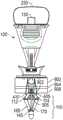
图21A和图21B描绘了带有随机旋转机构的多次-使用捕获器的实施例。在该实施例中,捕获器的支柱可在相对于手柄轴的限定距离内枢转。附接到支柱的薄膜可随其一起枢转。在图21A中,为清楚起见,画出单个支柱2010,但是以下描述适用于捕获器的其他支柱。捕获器支柱2010在轴2005中的窗2020内可绕一角度2015自由枢转。窗2020的大小可限定捕获器支柱2010能够旋转多大程度。窗2020可设置在用于捕获器的每一个支柱的近端部分(例如,近端连接部分1115,图11)中,从而允许每一个单独支柱均在窗内自由移动。在远端接头和控制杆之间的连接是非固定,使得近端接头的旋转将导致整个捕获器的旋转。在该实施例中所允许的捕获器的随机旋转减小了两个针将精确地在同一地点处刺穿薄膜的可能性。图21B描绘了在薄膜上的刺穿模式,其可由如在图21A中那样配备有支柱的捕获器的旋转导致。在图21B中,薄膜2025示出刺痕2030a、2030b、2030c,其可由缝线传递器在单个针道(例如,针道155(图3))内的使用导致,因为捕获器和薄膜在角度2015内旋转。21A and 21B depict an embodiment of a multiple-use catcher with a random rotation mechanism. In this embodiment, the struts of the catcher are pivotable within a defined distance relative to the handle axis. The membrane attached to the strut can pivot with it. In Figure 21A, a
图21C描绘了带有针道的多次-使用捕获器的实施例,所述针道带有内部枢轴点。在插入点2110和窄道2120之间以及在离开点2115和窄道2120之间,针道2105可在直径方面比针或缝线传递器更大。窄道2120可以是针道2105的颈缩,或者仅仅是在针道2105内的某位置处用作枢轴点的隆起。在针或缝线传递器能够在针道2105内径向移动的情况下,窄道2120可起着枢轴点的作用,以促进通过移动针或缝线传递器的近端端部而相对于缝线捕获器2135的表面移动针或缝线传递器的远端端部,如通过示例性缝线传递器位置2125、2130绘出的。缝线传递器位置2125、2130示出,对于每个实施例,缝线传递器可以相对于轴2140和缝线捕获器2135以各种角度离开针道2105。改变的角度减小了针将在精确的同一位置处穿透缝线捕获器2135上的薄膜的可能性。在实施例中,针道2105可为沙漏形。在另外的实施例中,针道2105可不具有窄道2120,但是仍然允许示例性缝线传递器位置2125、2130在直径方面比针或缝线传递器总体上更大。Figure 21C depicts an embodiment of a multiple-use trap with a needle track with an internal pivot point. Between the
图21D描绘了手柄2200的顶视图,其提供捕获器薄膜的多次使用。在图21D中,多个针道对2205a和b、2210a和b,及2215a和b,每对均瞄准薄膜的不同的相应区域(未示出)。此外,转盘特征(未示出)可在手柄2200的顶部上旋转,以每次暴露一组针道。Figure 21D depicts a top view of
图21E描绘了采用自动笔旋转机构的多次-使用实施例的横截面。缝线捕获器的旋转可确保针或缝线传递器在薄膜的未使用地点处穿透薄膜。在实施例中,自动笔旋转机构2300或变型可用于实现此目的。机构2300包含将控制杆2305的上下运动转变成控制杆2305的旋转运动的特征。在控制杆2305连接到缝线捕获器的远端接头,以便控制杆2305的旋转导致远端接头的旋转的情况下,以及在缝线捕获器的近端接头允许缝线捕获器的旋转运动的情况下,控制杆2305的旋转将导致缝线捕获器的旋转。所得到的旋转的大小受到旋转机构2300的设计的控制,且可任意地大或者小。在这种实施例的变型中,控制杆2305的上下运动导致缝线捕获器的近端接头的旋转运动,在远端接头和控制杆之间的连接是非固定的,并且近端接头的旋转导致整个缝线捕获器的旋转。Figure 21E depicts a cross-section of a multiple-use embodiment employing a pen rotation mechanism. Rotation of the suture catcher ensures that the needle or suture passer penetrates the membrane at unused locations of the membrane. In an embodiment, an automatic
实施例可采用缝线传递器,其中末端被设计为接收缝线,该缝线被预装载在手柄上(参见例如,图18A和图18B,以及关于在手柄上装载缝线的文本)。在这种实施例中,缝线传递器的末端优选地能够:在进入腹部组织之前抓持缝线端部;在穿透待缝合的组织和捕获器薄膜(如果捕获器如此配备)的同时保留缝线端部;以及部署缝线端部。Embodiments may employ a suture passer in which the tip is designed to receive suture that is preloaded on the handle (see, eg, Figures 18A and 18B, and text on loading suture on the handle). In such an embodiment, the tip of the suture passer is preferably capable of: grasping the suture end prior to entry into the abdominal tissue; remaining while penetrating the tissue to be sutured and the trap membrane (if the trap is so equipped) a suture end; and a deployment suture end.
图22A-22D描绘了设计用于抓持、保留和部署缝线的缝线传递器的不同实施例。在图22A中,缝线传递器2400具有带有狭槽2410的固定末端2405,狭槽2410被构造成接合定位在针道2425的出口2420处的缝线2415。在图22B中,缝线传递器2430具有致动的末端2435,其带有夹持构件2440,用于在推进器械2455(例如,缝线传递器2430固有的驱动轴)时夹持缝线2445抵靠固定构件2450。在图22C中,缝线传递器2460具有抓持末端2465,其带有通过内部杆2475致动的针头2470,用于抓持缝线2480抵靠针管2485。图22D描绘了先前参考图2A和图2B描述的缝线传递器200的抓持末端以进行比较。缝线传递器的该实施例还可用于接收被预装载在手柄上的缝线。类似地,图22A-22C中的缝线传递器的实施例可在插入到手柄的针道内之前装载有缝线。在实施例中,所公开的针末端实施例中的任一个均可被构造成与所公开的针道中的任一个配合。22A-22D depict various embodiments of suture passers designed for grasping, retaining and deploying sutures. 22A, the
在用于部署装载在手柄上的缝线的过程的实施例中,在待缝合的组织通过手柄被夹置(参见例如,图8B)之后,缝线传递器被插入并通过针道,直到末端到达装载在手柄上的缝线为止。缝线然后被装载到缝线传递器上。然后缝线传递器被插入通过针道,以将缝线端部部署在捕获器上。取决于捕获器构造,缝线端部可通过在捕获器支柱的抓持距离内释放被部署,或者可通过被插入到捕获器薄膜中且然后释放被部署。在释放缝线之后,可抽出缝线传递器且插入到第二针道中,利用装载在手柄上的第二缝线重复上述过程。In an embodiment of a process for deploying suture loaded on a handle, after the tissue to be stapled is clamped by the handle (see eg, Figure 8B), a suture passer is inserted and passed through the needle track until the end until the suture loaded on the handle is reached. The suture is then loaded onto the suture transmitter. The suture passer is then inserted through the needle track to deploy the suture end on the catcher. Depending on the capture configuration, the suture ends can be deployed by releasing within the grasping distance of the capture strut, or by being inserted into the capture membrane and then released. After the suture is released, the suture passer can be withdrawn and inserted into the second needle track, and the above process repeated with the second suture loaded on the handle.
图23A和23B描绘了缝线传递器集成到手柄2500中的实施例的横截面。在图23A中,缝线传递器2505、2510分别位于针道2515、2520内且用于部署缝线。缝线传递器2505、2510可被设计为存在于针道2515、2520内。控制按钮2540(或控制杠杆,或控制滑动器)可在致动之后导致缝线传递器2505、2510行进通过针道2515、2520,抓持装载的缝线,从手柄2500的轴105延伸,并且穿透待缝合的组织,例如,腹部组织。缝线传递器2505、2510可然后将缝线部署到捕获器110上。23A and 23B depict cross-sections of embodiments in which a suture passer is integrated into
在实施例中,缝线传递器2505、2510可使用滚子和轨道2545以及控制按钮2540部署,以推进两个缝线传递器通过针道2515、2520从而部署缝线。滚子和轨道2545可包括在轨道2555内的连接到致动臂2560的滚子2550。控制按钮2540在被按压时可导致滚子和轨道2545以及致动臂2560朝着手柄2500的远端端部2525行进。致动臂2560然后推动缝线传递器2505、2510通过针道2515、2520以部署缝线。当臂2560沿远端方向行进时,滚子和轨道2545被构造成允许致动臂2560在手柄2500内朝内移动。在图23B中,控制按钮2540已经完全被压低,推动缝线传递器2505、2510延伸经过捕获器110,打开缝线传递器末端(参见例如,图22B-D),并且安置缝线(未示出)。控制按钮2540的运动已经露出控制按钮130,其如上文描述的控制捕获器110以及也许还控制滑动器115。该运动还导致滚子2550响应于致动臂2560沿着针道2515、2520的外形在轨道2555内朝内移动。在实施例中,控制按钮130和2540的功能通过单个控制按钮实施。In an embodiment, the
缝线输送装置的实施例可用于实践用于插入和抽出缝线传递器,以及用于捕捉、保留和紧固缝线的方法。在实施例中,薄膜性质影响捕捉、保留和紧固缝线。根据描述,在携带缝线的针或缝线传递器插入通过薄膜时,可释放缝线并且通过薄膜捕捉缝线。在捕获器然后闭合时,薄膜可随捕获器骨架闭合折叠,从而将缝线保留在薄膜内。薄膜本身可由具有高摩擦系数的材料制成,或者进一步具有增大薄膜的缝线-保留性质的设计。保留性质可随材料厚度、或者材料层的数量、或者材料表面变化。保留性质可在保留表面的一侧或者全部两侧上。Embodiments of the suture delivery device can be used to practice methods for inserting and withdrawing suture transmitters, and for capturing, retaining, and securing sutures. In embodiments, film properties affect the capture, retention and fastening of sutures. As described, when a suture-carrying needle or suture passer is inserted through the membrane, the suture can be released and captured by the membrane. When the trap is then closed, the membrane can be folded closed with the trap backbone, leaving the suture within the membrane. The membrane itself may be made of a material with a high coefficient of friction, or further designed to increase the suture-retention properties of the membrane. The retention properties can vary with the thickness of the material, or the number of layers of the material, or the surface of the material. The retention properties can be on one side or both sides of the retention surface.
在实施例中,缝线可通过捕获器支柱边缘紧固。可采用若干方法(单独地或组合地)以确保缝线被紧固到装置的远端端部。在缝线输送装置从外科手术开口抽出期间,可使用缝线的机械夹持以保留缝线。邻近支柱的边缘可用于紧固地保持缝线(作为机械夹持件)。对于其中缝线捕获器配备有薄膜的实施例,薄膜保留力可能不足以经受通过缝合的组织施加在缝线上的力,即使在缝线与薄膜适当地接合时。因此,邻近的捕获器支柱可用作夹持件以紧固缝线。这种邻近的支柱可独立地使用(例如,在不包括薄膜的捕获器实施例中),或者可结合薄膜使用(例如,在包括薄膜的捕获器实施例中)。In an embodiment, the suture may be fastened through the edge of the catch strut. Several methods (alone or in combination) can be employed to ensure that the suture is secured to the distal end of the device. Mechanical gripping of the suture may be used to retain the suture during withdrawal of the suture delivery device from the surgical opening. The edge adjacent to the strut can be used to hold the suture securely (as a mechanical grip). For embodiments in which the suture catcher is equipped with a membrane, the membrane retention force may not be sufficient to withstand the forces exerted on the suture by the sutured tissue, even when the suture is properly engaged with the membrane. Thus, the adjacent catcher struts can serve as clamps to fasten the suture. Such adjacent struts may be used independently (eg, in trap embodiments that do not include membranes), or may be used in conjunction with membranes (eg, in trap embodiments that include membranes).
图24A-24E描绘了捕获器的实施例,其改变了夹持表面的长度,或者夹持表面的数目、或接触点的数目。在图24A中,支柱2620的支柱边缘2605、2610已经弯曲以增大与缝线2615的接触表面。也就是说,捕获器骨架支柱的边缘已经倾斜,且在倾斜边缘的长度上,缝线与支柱相接触。在图24B中,支柱2625、2630被构造成形成抵靠缝线2615的单个接触点2635。在图24C中,支柱2640与支柱2650的大小不同。缝线2615被夹持在一对不同大小的支柱2640、2650的表面之间。在图24D中,支柱边缘2655、2660接合,从而在缝线接触表面2665中形成角度。该角度可例如为90度。捕获器支柱还可沿着缝线接触边缘具有锯齿或波浪形边缘。带有这种边缘的设计的优势是施加到缝线的力的方向被改变,从而增大在沿着缝线的各点处的法向力。在图24E中,支柱2670被添加到图24B的构造,从而形成额外的缝线接触点2637。24A-24E depict embodiments of catchers that vary the length of the gripping surfaces, or the number of gripping surfaces, or the number of contact points. In FIG. 24A, strut edges 2605, 2610 of
在实施例中,作为对刚刚讨论的各种支柱设计的补充,支柱边缘可被粗糙化、处理、涂覆或以其他方式处理以增大摩擦并且增强缝线-紧固性能。例如,橡胶衬垫或带,或者橡胶涂层可施用到支柱边缘。In embodiments, in addition to the various strut designs just discussed, strut edges may be roughened, treated, coated, or otherwise treated to increase friction and enhance suture-fastening properties. For example, rubber pads or straps, or a rubber coating can be applied to the edge of the strut.
在捕获器的替代实施例中,缝线可在朝内折叠的捕获器支柱之间被夹持抵靠控制杆,或者抵靠绕控制杆定位的块,在支柱朝内折叠时,该块对支柱呈现平坦表面。在这种实施例中,薄膜以及缝线都可被夹持在外部元件(支柱)和内部元件(控制杆或绕控制杆的块)之间。由于夹持缝线的有效性可与缝线捕获器的充分(或者完全)闭合相关联,所以所施加的闭合力的水平以及由薄膜导致的任何干扰均可影响夹持有效性。In alternate embodiments of the catcher, the suture may be clamped against the lever between the inwardly folded catcher struts, or against a block positioned about the lever, which when the struts are folded inwards The struts present a flat surface. In such an embodiment, both the membrane and the suture may be clamped between the outer element (the strut) and the inner element (the lever or block around the lever). Since the effectiveness of gripping the suture can be correlated with adequate (or complete) closure of the suture catcher, the level of closure force applied and any disturbance caused by the membrane can affect the gripping effectiveness.
在缝线捕获器的各种实施例中,增加支柱闭合力可增大在缝线上的保留力。因此,在缝线输送装置从外科手术开口的更有力的抽取期间捕获器仍可保留缝线。In various embodiments of the suture catcher, increasing the strut closure force can increase the retention force on the suture. Thus, the catch can still retain the suture during more vigorous withdrawal of the suture delivery device from the surgical opening.
在实施例中,缝线可通过没有捕捉表面(例如,薄膜)的捕获器保留。在这种实施例中,捕获器的支柱可直接夹持缝线。夹持作用可例如是被收回以从外科手术开口中抽取的捕获器的一部分。In an embodiment, the suture may be retained by a catcher without a catchment surface (eg, a membrane). In such an embodiment, the struts of the catcher can hold the suture directly. The gripping action may be, for example, a portion of the catch that is retracted for extraction from the surgical opening.
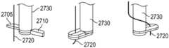
图25-27描绘了用于输送以及捕获缝线的另外的实施例。图25A、图25B以及图26描绘了用于在外科手术开口的一侧捕捉缝线且将缝线移动到另一侧以完成缝合的实施例。图25A和图25B分别描绘了夹持器械2700的顶视图以及透视图,该器械2700带有分别在方向2707、2712上枢转以捕捉缝线端部2720的夹持臂2705、2710。夹持臂2705可通过内部轴2725旋转,以及夹持臂2710可通过外部轴2730旋转。夹持器械2700可代替在例如图1A以及图1B的手柄100上的捕获器110。夹持器械2700可用于捕捉缝线2720以及在外科手术开口内定位在夹持器械2700的相对侧上。25-27 depict additional embodiments for delivering and capturing sutures. 25A, 25B, and 26 depict an embodiment for capturing a suture on one side of a surgical opening and moving the suture to the other side to complete suturing. 25A and 25B depict top and perspective views, respectively, of a
图26描绘了带有通过支柱2810支撑的大区域的薄膜2805的捕获器械2800的透视图,支柱2810围绕轴2815枢转以将捕捉的缝线2820安置在捕获器械2800的相对侧上。缝线2820可如先前讨论的通过薄膜2805捕捉。捕获器械2800还可代替在例如图1A以及图1B的手柄100上的捕获器110。26 depicts a perspective view of a
实施例可包括伞状薄膜,其中,薄膜通过若干径向展开的支柱支撑且围绕装置跨越360度。类似于伞,薄膜可处于张紧状态,使得针更容易穿透薄膜材料。同样,在抽出缝线传递器时,在薄膜材料和缝线之间的摩擦可能足以使缝线脱离并保留缝线。替代实施例可包括多-层薄膜,其中,每一层均具有不同的定向。在这种多层薄膜中,由于摩擦以及在格状结构中变得缠绕,缝线可能从缝线传递器脱离。Embodiments may include umbrella-shaped membranes, wherein the membrane is supported by several radially deployed struts and spans 360 degrees around the device. Similar to an umbrella, the membrane can be in tension, making it easier for needles to penetrate the membrane material. Also, when the suture transmitter is withdrawn, the friction between the film material and the suture may be sufficient to dislodge the suture and retain the suture. Alternative embodiments may include multi-layer films, where each layer has a different orientation. In such multi-layer films, the suture may become detached from the suture transmitter due to friction and becoming entangled in the lattice structure.
通过图25A、图25B以及图26绘出的实施例可根据以下方法使用。使用配备有夹持器械2700或捕获器械2800的手柄,将携带缝线的针(或缝线传递器)插入到针道中并且然后插入到套管针伤口的一侧上的肌肉/筋膜层中。缝线传递器释放缝线且被抽出。对于夹持器械2700,缝线然后通过夹持臂2705、2710的运动被捕捉。对于捕获器械2800,缝线已经穿透薄膜2805,薄膜2805具有用以使缝线从针传递器脱离并且保留缝线的材料性质或设计。一旦缝线被保留,缝线就可通过旋转器械2700或2800移动,从而导致缝线2720或2820重新定位到套管针伤口的相对侧。外科医生可然后容易地取回缝线,因为缝线定位在插入通过手柄的另一个针道以及通过待缝合的组织的针(或缝线传递器)的目标点处。一旦通过待缝合的组织,针(或缝线传递器)就可在腹腔镜影像的指导下,捕捉重新定位的缝线。所捕捉的缝线可具有控制的形状、定向以及张力,其将促进外科医生取回其。类似于先前实施例,这些实施例移除了对于帮助将缝线移动到外科医生能够利用缝线传递器抓持缝线的地方处的辅助者的需要。The embodiments depicted by Figures 25A, 25B, and 26 may be used according to the following methods. Using a handle equipped with a
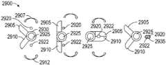
图27描绘了用于在外科手术开口内链接缝线端部的实施例的顶视图。在图27中,夹持器械2900具有夹持臂2905、2910,其分别在方向2907、2912上枢转以掠过一弧度并且捕捉缝线端部2920、2922。夹持臂2905可通过内部轴2925旋转,以及夹持臂2910可通过外部轴2930旋转(替代地,仅一个夹持臂旋转以捕捉两个缝线端部)。夹持器械2900可代替在例如图1A以及图1B的手柄100上的捕获器110。夹持器械2900可用于捕捉缝线端部2920、2922,且利用链接元件2935将它们链接在一起。链接元件2935可以是固定到夹持臂2905、2910中的一个的卷曲件或生物可降解构件。其还可为夹持件或夹子。额外地,缝线端部2920、2922可使用粘合剂或热量等链接。所得到的缝线链接部应当至少坚固到足以承受将缝线接头牵拉通过由针或缝线传递器创造的组织轨道。替代地,缝线链接部应当坚固到足以提供伤口闭合。27 depicts a top view of an embodiment for linking suture ends within a surgical opening. In Figure 27, gripping
夹持器械2900可根据以下方法使用。扫掠件(sweepers)或夹持臂最初定位成不干涉缝线输送。两个缝线端部在套管针伤口的相对侧上输送。夹持臂然后旋转,以使缝线端部与链接元件接触。缝线端部以及链接元件然后通过夹持臂按压在一起,以链接缝线。然后可抽出缝线输送装置。The
在这种实施例的情况下,用于结束缝线的一个选项涉及输送一条缝线的两个端部。一旦两个缝线端部链接,链接的缝线变成环。用户可在近端端部处-套管针伤口外侧的割断缝线。然后,用户可牵拉外部缝线端部以闭合伤口,且然后对端部打结。替代地,用户可利用缝线输送装置牵拉缝线链接处(link out)通过外科手术开口,或者在缝线环的一侧上拖拽以将链接处带出通过由最始针插入创造的组织轨道。用户可然后割断缝线接头,闭合外科手术开口以及打结。其他选项是将两个缝线端部输送到腹部内,每个端均来自单独的缝线。一旦两个缝线端部链接,用户就可如上所述抽出装置并完成缝合。With this embodiment, one option for ending the suture involves delivering both ends of a suture. Once the two stitch ends are linked, the linked stitch becomes a loop. The user can cut the suture at the proximal end - outside of the trocar wound. The user can then pull the outer suture ends to close the wound, and then tie the ends. Alternatively, the user may use the suture delivery device to pull the suture link out through the surgical opening, or drag on one side of the suture loop to bring the link out through the opening created by the initial needle insertion. Organizing tracks. The user can then cut the suture joint, close the surgical opening, and tie the knot. Other options are to deliver two suture ends into the abdomen, each from a separate suture. Once the two suture ends are linked, the user can withdraw the device and complete the suture as described above.
在实施例中,捕获器闭合机构是滑动器激活的。缝线输送装置可具有滑动构件,其能够在腹腔中定位成夹置腹壁组织抵靠反作用力构件(例如,捕获器)。所描述的许多实施例以这种方式构造。在该实施例中,滑动构件可联接到捕获器展开机构,以便滑动构件的运动可用于控制捕获器打开和闭合。在滑动构件联接到展开机构的情况下,当滑动构件朝下移动(朝着装置的远端端部)时,捕获器展开机构可被致动以打开捕获器。在滑动构件朝上(朝着装置的近端端部)移动时,捕获器展开机构可被致动以闭合捕获器。在其处滑动构件与捕获器展开机构互相作用的位置可按照需要被设计。在一个实施例中,在滑动构件朝下行进小的距离时,捕获器可被打开,而在滑动构件朝上行进小的距离时捕获器可被闭合。例如,朝下移动滑动器可导致远端接头朝上移动,并且因此展开缝线捕获器。各种机构选项可用于实现这种理念。In an embodiment, the catch closure mechanism is slider activated. The suture delivery device may have a sliding member positionable in the abdominal cavity to clamp abdominal wall tissue against a reaction force member (eg, a catch). Many of the described embodiments are constructed in this manner. In this embodiment, the slide member may be coupled to the catch deployment mechanism so that movement of the slide member may be used to control the catch opening and closing. With the slide member coupled to the deployment mechanism, when the slide member is moved downward (toward the distal end of the device), the catch deployment mechanism can be actuated to open the catch. When the slide member is moved upward (toward the proximal end of the device), the catch deployment mechanism can be actuated to close the catch. The location at which the slide member interacts with the catch deployment mechanism can be designed as desired. In one embodiment, the catch may be opened when the sliding member travels a small distance downward, and the catch may be closed when the sliding member travels a small distance upward. For example, moving the slider downward may cause the distal fitting to move upward and thus deploy the suture catcher. Various institutional options are available to implement this philosophy.
一种用于使用实施例的方法可包括:将缝线输送装置插入通过组织轨道直到远端端部在腔内部为止;朝装置远端端部移动滑动构件以打开捕获器并且然后将腹壁组织夹置在捕获器和滑动构件之间;通过将携带缝线的针插入到装置中将缝线输送到缝线保留元件(捕获器)直到缝线被释放并且被保留在远端端部处为止(或直到缝线被释放并且通过捕获器被捕捉为止);朝装置的近端端部移动滑动构件以闭合捕获器并且释放腹壁组织;以及在缝线端部保留在装置的远端端部处的情况下,从腔中抽出缝线输送装置。A method for using an embodiment may include: inserting a suture delivery device through a tissue track until the distal end is inside the lumen; moving a sliding member toward the distal end of the device to open the trap and then clipping the abdominal wall tissue placed between the catch and the sliding member; the suture is delivered to the suture retention element (the catch) by inserting a suture-carrying needle into the device until the suture is released and retained at the distal end ( or until the suture is released and captured by the catch); moving the sliding member toward the proximal end of the device to close the catch and release the abdominal wall tissue; and the suture end remaining at the distal end of the device case, the suture delivery device is withdrawn from the lumen.
用于自动地部署缝线的方法可包括:将缝线输送装置插入到外科手术开口中;夹置伤口组织;部署缝线端部,以及抽出手柄。夹置伤口组织还可包括:按压按钮,这导致捕获器打开以及滑动器压缩组织抵靠捕获器。部署缝线端部还可包括:使用独立的缝线传递器,或者使用与手柄集成的缝线传递器。抽出手柄还可包括:闭合捕获器以捕捉缝线,以及自动的缝线释放。A method for automatically deploying a suture may include: inserting a suture delivery device into a surgical opening; clipping wound tissue; deploying a suture end, and withdrawing a handle. Clipping wound tissue may also include pressing a button, which causes the trap to open and the slider to compress the tissue against the trap. Deploying the suture tip may also include using a separate suture passer, or using a suture passer integrated with the handle. The withdrawal handle may also include: closing the catcher to capture the suture, and automatic suture release.
用于部署缝线的方法可包括:将缝线装载到手柄上,或者将缝线盒装载到手柄中;利用左手,移除套管针;利用右手,将手柄插入到套管针伤口中直到捕获器从腹腔镜影像中完全可见为止;利用右手,释放控制按钮,其打开捕获器且然后向下推动滑动器以在视觉指导下夹置组织。腹腔镜影像可用于示出捕获器是否与腹膜壁接触。在实施例中,用于部署缝线的这种方法可选地包括:利用左手,保持手柄;利用右手,在视觉指导下将缝线传递器插入通过针道以将缝线部署在捕获器上;以及在视觉指导下利用另一个针道重复该过程。在另一个实施例中,用于部署缝线的这种方法可选地包括:使用左手,保持手柄;使用右手,在视觉指导下推动部署按钮以将缝线部署在捕获器上;使用左手拇指,在视觉指导下按压控制按钮以捕捉缝线;以及使用左手,向外牵拉手柄以及取得两个缝线端部。The method for deploying the suture may include: loading the suture onto the handle, or loading the suture cartridge into the handle; using the left hand, removing the trocar; using the right hand, inserting the handle into the trocar wound until Until the trap is fully visible from the laparoscopic image; with the right hand, release the control button, which opens the trap and then pushes the slider down to clamp the tissue under visual guidance. Laparoscopic images can be used to show whether the trap is in contact with the peritoneal wall. In an embodiment, such a method for deploying a suture optionally includes: using the left hand, holding the handle; using the right hand, inserting a suture passer through the needle track under visual guidance to deploy the suture on the catcher ; and repeat the process with another needle track under visual guidance. In another embodiment, this method for deploying a suture optionally includes: using the left hand, holding the handle; using the right hand, pushing the deployment button with visual guidance to deploy the suture on the catcher; using the thumb of the left hand , press the control button with visual guidance to capture the suture; and using the left hand, pull the handle outward and obtain both suture ends.
本文中所述的是特定示例性实施例。然而,与本实施例相关的本领域技术人员将理解的是本公开的原理能够利用适当的修改容易地扩展到其他应用。Described herein are specific exemplary embodiments. However, those skilled in the art to which the present embodiments pertain will appreciate that the principles of the present disclosure can be readily extended to other applications with appropriate modification.
Claims (17)
Applications Claiming Priority (3)
| Application Number | Priority Date | Filing Date | Title |
|---|---|---|---|
| US201461937089P | 2014-02-07 | 2014-02-07 | |
| US61/937089 | 2014-02-07 | ||
| PCT/US2015/014797WO2015120258A1 (en) | 2014-02-07 | 2015-02-06 | Suture delivery device for suturing tissue |
Publications (2)
| Publication Number | Publication Date |
|---|---|
| CN106470619A CN106470619A (en) | 2017-03-01 |
| CN106470619Btrue CN106470619B (en) | 2020-10-20 |
Family
ID=53773907
Family Applications (1)
| Application Number | Title | Priority Date | Filing Date |
|---|---|---|---|
| CN201580017947.6AActiveCN106470619B (en) | 2014-02-07 | 2015-02-06 | Suture delivery device for suturing tissue |
Country Status (13)
| Country | Link |
|---|---|
| US (1) | US10307144B2 (en) |
| EP (1) | EP3102120B1 (en) |
| JP (1) | JP6534674B2 (en) |
| KR (1) | KR102367518B1 (en) |
| CN (1) | CN106470619B (en) |
| AU (1) | AU2015213812B2 (en) |
| CA (1) | CA2938858C (en) |
| ES (1) | ES2904356T3 (en) |
| IL (1) | IL247108B (en) |
| MX (1) | MX382012B (en) |
| PL (1) | PL3102120T3 (en) |
| TW (1) | TWI648027B (en) |
| WO (1) | WO2015120258A1 (en) |
Families Citing this family (9)
| Publication number | Priority date | Publication date | Assignee | Title |
|---|---|---|---|---|
| US20240138823A1 (en)* | 2013-05-07 | 2024-05-02 | Amsel Medical Corporation | Methods and apparatus for fastening and clamping tissues with tissue protector |
| CN106214196B (en)* | 2016-07-20 | 2018-12-04 | 江苏三联星海医疗器械股份有限公司 | A kind of deep fascia stitching unstrument |
| IL264759B2 (en)* | 2016-08-11 | 2023-09-01 | Medeon Biodesign Inc | Suture delivery device for suturing tissue |
| US11389192B2 (en)* | 2017-06-29 | 2022-07-19 | Cilag Gmbh International | Method of suturing a trocar path incision |
| CN109620322B (en)* | 2019-01-23 | 2024-08-20 | 上海执中医疗技术有限公司 | Fixed poking card with incision stitching function |
| CN110613490B (en)* | 2019-09-03 | 2024-11-29 | 潘隽玮 | Semi-automatic rotary escapement system |
| WO2021059278A1 (en)* | 2019-09-24 | 2021-04-01 | Gordian Surgical Ltd | Trocar incision closure kit and method of assembling the same |
| CN113520542B (en)* | 2021-06-24 | 2023-03-31 | 浙江优亿医疗器械股份有限公司 | Laparoscope puncture outfit with fascia closing function |
| US20240115257A1 (en)* | 2022-10-11 | 2024-04-11 | Robert Lee Bromley | Integrated Closure Device |
Family Cites Families (23)
| Publication number | Priority date | Publication date | Assignee | Title |
|---|---|---|---|---|
| DE4137218C1 (en)* | 1991-11-13 | 1993-02-11 | Heidmueller, Harald, 5000 Koeln, De | |
| US5984948A (en)* | 1997-04-14 | 1999-11-16 | Hasson; Harrith M. | Device for closing an opening in tissue and method of closing a tissue opening using the device |
| US5830232A (en)* | 1997-04-14 | 1998-11-03 | Hasson; Harrith M. | Device for closing an opening in tissue and method of closing a tissue opening using the device |
| US20040087978A1 (en)* | 2002-08-27 | 2004-05-06 | Velez Juan Manuel | Surgical fascia closure instrument, guide and method |
| US20040068273A1 (en)* | 2002-10-02 | 2004-04-08 | Ibionics Corporation | Automatic laparoscopic incision closing apparatus |
| ZA200610827B (en)* | 2004-05-21 | 2008-07-30 | Neatstich Ltd | Suture device |
| US8992549B2 (en)* | 2004-08-05 | 2015-03-31 | Teleflex Medical Incorporated | Laparoscopic port site closure tool |
| US20070203507A1 (en)* | 2005-08-26 | 2007-08-30 | G-Surge Medical Solutions, Inc. | Suturing apparatus and methods |
| US8562629B2 (en) | 2006-10-24 | 2013-10-22 | Arthrocare Corporation | Suture device having selective needle actuation and related method |
| DE102008053809A1 (en) | 2008-10-29 | 2010-05-12 | Medi-Globe Gmbh | Surgical thread positioning system for closing an opening within a tissue wall |
| US9414820B2 (en)* | 2009-01-09 | 2016-08-16 | Abbott Vascular Inc. | Closure devices, systems, and methods |
| US9486191B2 (en)* | 2009-01-09 | 2016-11-08 | Abbott Vascular, Inc. | Closure devices |
| JP5720031B2 (en)* | 2009-01-12 | 2015-05-20 | テレフレックス メディカル インコーポレイテッドTeleflex Medical Incorporated | Apparatus and method for tissue closure |
| US20110082475A1 (en)* | 2009-10-01 | 2011-04-07 | Tyco Healthcare Group Lp | Wound closure device including ferrule ejector system |
| US8906042B2 (en) | 2010-07-29 | 2014-12-09 | Covidien Lp | Wound closure device including mesh barrier |
| US20120191109A1 (en)* | 2011-01-24 | 2012-07-26 | Brian Rockrohr | Wound closure device using t-shaped tag |
| US20130035701A1 (en) | 2011-08-04 | 2013-02-07 | Suture Ease, LLC | Dual insufflation and wound closure devices ans methods |
| EP2797519B1 (en)* | 2011-12-27 | 2023-05-31 | CooperSurgical, Inc. | Suture passer guides and related kits |
| CA2860645C (en) | 2012-01-04 | 2019-11-05 | Teleflex Medical Incorporated | Apparatus and methods for tissue closure |
| US9393011B2 (en) | 2012-03-13 | 2016-07-19 | Suture Ease, Inc. | Needle and snare guide apparatus for passing suture |
| WO2013172916A1 (en) | 2012-05-18 | 2013-11-21 | Coopersurgical, Inc. | Suture passer guides and related kits and methods |
| CN103494621B (en)* | 2013-08-30 | 2016-02-24 | 北京派尔特医疗科技股份有限公司 | A kind of purse-string forceps and line storehouse thereof |
| AU2014364043B2 (en) | 2013-12-09 | 2017-06-29 | Teleflex Medical Incorporated | Laparoscopic fascial closure system |
- 2015
- 2015-02-06WOPCT/US2015/014797patent/WO2015120258A1/enactiveApplication Filing
- 2015-02-06MXMX2016010242Apatent/MX382012B/enunknown
- 2015-02-06USUS14/615,786patent/US10307144B2/enactiveActive
- 2015-02-06ESES15746966Tpatent/ES2904356T3/enactiveActive
- 2015-02-06CNCN201580017947.6Apatent/CN106470619B/enactiveActive
- 2015-02-06AUAU2015213812Apatent/AU2015213812B2/ennot_activeCeased
- 2015-02-06PLPL15746966Tpatent/PL3102120T3/enunknown
- 2015-02-06JPJP2016550270Apatent/JP6534674B2/enactiveActive
- 2015-02-06EPEP15746966.9Apatent/EP3102120B1/enactiveActive
- 2015-02-06TWTW104104145Apatent/TWI648027B/enactive
- 2015-02-06KRKR1020167024619Apatent/KR102367518B1/enactiveActive
- 2015-02-06CACA2938858Apatent/CA2938858C/enactiveActive
- 2016
- 2016-08-04ILIL247108Apatent/IL247108B/enactiveIP Right Grant
Also Published As
| Publication number | Publication date |
|---|---|
| JP2017505193A (en) | 2017-02-16 |
| WO2015120258A1 (en) | 2015-08-13 |
| AU2015213812B2 (en) | 2019-07-25 |
| KR20160123326A (en) | 2016-10-25 |
| KR102367518B1 (en) | 2022-02-25 |
| TWI648027B (en) | 2019-01-21 |
| EP3102120B1 (en) | 2021-11-03 |
| MX382012B (en) | 2025-03-13 |
| EP3102120A1 (en) | 2016-12-14 |
| US20150223804A1 (en) | 2015-08-13 |
| PL3102120T3 (en) | 2022-03-21 |
| CA2938858C (en) | 2022-08-30 |
| MX2016010242A (en) | 2017-02-23 |
| EP3102120A4 (en) | 2017-12-20 |
| IL247108A0 (en) | 2016-09-29 |
| AU2015213812A1 (en) | 2016-08-25 |
| JP6534674B2 (en) | 2019-06-26 |
| ES2904356T3 (en) | 2022-04-04 |
| US10307144B2 (en) | 2019-06-04 |
| CN106470619A (en) | 2017-03-01 |
| IL247108B (en) | 2020-11-30 |
| CA2938858A1 (en) | 2015-08-13 |
| TW201538117A (en) | 2015-10-16 |
Similar Documents
| Publication | Publication Date | Title |
|---|---|---|
| CN106470619B (en) | Suture delivery device for suturing tissue | |
| US12376839B2 (en) | Laparoscopic port site closure tool | |
| US10327761B2 (en) | Suture delivery device for suturing tissue | |
| EP2037820B1 (en) | Low profile tissue anchors and tissue anchor systems | |
| US20110190793A1 (en) | Methods and apparatuses for suturing of cardiac openings | |
| US9492072B2 (en) | Laparoscopic surgical device | |
| CN110213996B (en) | Suture delivery device for suturing tissue | |
| EP2806804A2 (en) | Apparatus and method for heart valve repair |
Legal Events
| Date | Code | Title | Description |
|---|---|---|---|
| PB01 | Publication | ||
| PB01 | Publication | ||
| SE01 | Entry into force of request for substantive examination | ||
| SE01 | Entry into force of request for substantive examination | ||
| GR01 | Patent grant | ||
| GR01 | Patent grant |