CN1064598C - Ink jet recording device and temperature control method thereof - Google Patents
Ink jet recording device and temperature control method thereofDownload PDFInfo
- Publication number
- CN1064598C CN1064598CCN90108978ACN90108978ACN1064598CCN 1064598 CCN1064598 CCN 1064598CCN 90108978 ACN90108978 ACN 90108978ACN 90108978 ACN90108978 ACN 90108978ACN 1064598 CCN1064598 CCN 1064598C
- Authority
- CN
- China
- Prior art keywords
- temperature
- recording
- recording head
- printing
- time
- Prior art date
- Legal status (The legal status is an assumption and is not a legal conclusion. Google has not performed a legal analysis and makes no representation as to the accuracy of the status listed.)
- Expired - Fee Related
Links
Images


Classifications
- B—PERFORMING OPERATIONS; TRANSPORTING
- B41—PRINTING; LINING MACHINES; TYPEWRITERS; STAMPS
- B41J—TYPEWRITERS; SELECTIVE PRINTING MECHANISMS, i.e. MECHANISMS PRINTING OTHERWISE THAN FROM A FORME; CORRECTION OF TYPOGRAPHICAL ERRORS
- B41J2/00—Typewriters or selective printing mechanisms characterised by the printing or marking process for which they are designed
- B41J2/005—Typewriters or selective printing mechanisms characterised by the printing or marking process for which they are designed characterised by bringing liquid or particles selectively into contact with a printing material
- B41J2/01—Ink jet
- B41J2/015—Ink jet characterised by the jet generation process
- B41J2/04—Ink jet characterised by the jet generation process generating single droplets or particles on demand
- B41J2/045—Ink jet characterised by the jet generation process generating single droplets or particles on demand by pressure, e.g. electromechanical transducers
- B41J2/04501—Control methods or devices therefor, e.g. driver circuits, control circuits
- B41J2/04528—Control methods or devices therefor, e.g. driver circuits, control circuits aiming at warming up the head
- B—PERFORMING OPERATIONS; TRANSPORTING
- B41—PRINTING; LINING MACHINES; TYPEWRITERS; STAMPS
- B41J—TYPEWRITERS; SELECTIVE PRINTING MECHANISMS, i.e. MECHANISMS PRINTING OTHERWISE THAN FROM A FORME; CORRECTION OF TYPOGRAPHICAL ERRORS
- B41J2/00—Typewriters or selective printing mechanisms characterised by the printing or marking process for which they are designed
- B41J2/005—Typewriters or selective printing mechanisms characterised by the printing or marking process for which they are designed characterised by bringing liquid or particles selectively into contact with a printing material
- B41J2/01—Ink jet
- B41J2/015—Ink jet characterised by the jet generation process
- B41J2/04—Ink jet characterised by the jet generation process generating single droplets or particles on demand
- B41J2/045—Ink jet characterised by the jet generation process generating single droplets or particles on demand by pressure, e.g. electromechanical transducers
- B41J2/04501—Control methods or devices therefor, e.g. driver circuits, control circuits
- B41J2/04553—Control methods or devices therefor, e.g. driver circuits, control circuits detecting ambient temperature
- B—PERFORMING OPERATIONS; TRANSPORTING
- B41—PRINTING; LINING MACHINES; TYPEWRITERS; STAMPS
- B41J—TYPEWRITERS; SELECTIVE PRINTING MECHANISMS, i.e. MECHANISMS PRINTING OTHERWISE THAN FROM A FORME; CORRECTION OF TYPOGRAPHICAL ERRORS
- B41J2/00—Typewriters or selective printing mechanisms characterised by the printing or marking process for which they are designed
- B41J2/005—Typewriters or selective printing mechanisms characterised by the printing or marking process for which they are designed characterised by bringing liquid or particles selectively into contact with a printing material
- B41J2/01—Ink jet
- B41J2/015—Ink jet characterised by the jet generation process
- B41J2/04—Ink jet characterised by the jet generation process generating single droplets or particles on demand
- B41J2/045—Ink jet characterised by the jet generation process generating single droplets or particles on demand by pressure, e.g. electromechanical transducers
- B41J2/04501—Control methods or devices therefor, e.g. driver circuits, control circuits
- B41J2/0458—Control methods or devices therefor, e.g. driver circuits, control circuits controlling heads based on heating elements forming bubbles
- B—PERFORMING OPERATIONS; TRANSPORTING
- B41—PRINTING; LINING MACHINES; TYPEWRITERS; STAMPS
- B41J—TYPEWRITERS; SELECTIVE PRINTING MECHANISMS, i.e. MECHANISMS PRINTING OTHERWISE THAN FROM A FORME; CORRECTION OF TYPOGRAPHICAL ERRORS
- B41J2/00—Typewriters or selective printing mechanisms characterised by the printing or marking process for which they are designed
- B41J2/005—Typewriters or selective printing mechanisms characterised by the printing or marking process for which they are designed characterised by bringing liquid or particles selectively into contact with a printing material
- B41J2/01—Ink jet
- B41J2/015—Ink jet characterised by the jet generation process
- B41J2/04—Ink jet characterised by the jet generation process generating single droplets or particles on demand
- B41J2/045—Ink jet characterised by the jet generation process generating single droplets or particles on demand by pressure, e.g. electromechanical transducers
- B41J2/04501—Control methods or devices therefor, e.g. driver circuits, control circuits
- B41J2/04591—Width of the driving signal being adjusted
- B—PERFORMING OPERATIONS; TRANSPORTING
- B41—PRINTING; LINING MACHINES; TYPEWRITERS; STAMPS
- B41J—TYPEWRITERS; SELECTIVE PRINTING MECHANISMS, i.e. MECHANISMS PRINTING OTHERWISE THAN FROM A FORME; CORRECTION OF TYPOGRAPHICAL ERRORS
- B41J2/00—Typewriters or selective printing mechanisms characterised by the printing or marking process for which they are designed
- B41J2/005—Typewriters or selective printing mechanisms characterised by the printing or marking process for which they are designed characterised by bringing liquid or particles selectively into contact with a printing material
- B41J2/01—Ink jet
- B41J2/17—Ink jet characterised by ink handling
- B41J2/195—Ink jet characterised by ink handling for monitoring ink quality
- B—PERFORMING OPERATIONS; TRANSPORTING
- B41—PRINTING; LINING MACHINES; TYPEWRITERS; STAMPS
- B41J—TYPEWRITERS; SELECTIVE PRINTING MECHANISMS, i.e. MECHANISMS PRINTING OTHERWISE THAN FROM A FORME; CORRECTION OF TYPOGRAPHICAL ERRORS
- B41J2/00—Typewriters or selective printing mechanisms characterised by the printing or marking process for which they are designed
- B41J2/005—Typewriters or selective printing mechanisms characterised by the printing or marking process for which they are designed characterised by bringing liquid or particles selectively into contact with a printing material
- B41J2/01—Ink jet
- B41J2/135—Nozzles
- B41J2/14—Structure thereof only for on-demand ink jet heads
- B41J2002/14362—Assembling elements of heads
- B—PERFORMING OPERATIONS; TRANSPORTING
- B41—PRINTING; LINING MACHINES; TYPEWRITERS; STAMPS
- B41J—TYPEWRITERS; SELECTIVE PRINTING MECHANISMS, i.e. MECHANISMS PRINTING OTHERWISE THAN FROM A FORME; CORRECTION OF TYPOGRAPHICAL ERRORS
- B41J2/00—Typewriters or selective printing mechanisms characterised by the printing or marking process for which they are designed
- B41J2/005—Typewriters or selective printing mechanisms characterised by the printing or marking process for which they are designed characterised by bringing liquid or particles selectively into contact with a printing material
- B41J2/01—Ink jet
- B41J2/135—Nozzles
- B41J2/14—Structure thereof only for on-demand ink jet heads
- B41J2002/14379—Edge shooter
Landscapes
- Engineering & Computer Science (AREA)
- Quality & Reliability (AREA)
- Ink Jet (AREA)
- Particle Formation And Scattering Control In Inkjet Printers (AREA)
- Recording Measured Values (AREA)
Abstract
Description
Translated fromChinese本发明涉及一种墨水喷射记录装置及其温度控制方法,该装置可以从记录头向记录材料喷射墨水从而进行记录。The present invention relates to an inkjet recording device capable of recording by ejecting ink from a recording head to a recording material and its temperature control method.
打印机、复印机、传真机等记录装置,都是根据图象信息,在纸塑料薄板等记录材料上记录由点图形所组成的图形。Recording devices such as printers, copiers, and facsimile machines all record graphics composed of dot graphics on recording materials such as paper and plastic sheets based on image information.
上述记录装置按其记录方式的不同,可分为墨水喷射式、点式、感热式以及激光光束式等类型。其中,墨水喷射式(墨水喷射记录装置)是这样构成的,使墨水(记录液)液滴从记录头的喷出口喷出、飞溅到记录材料上并附着于其上,从而进行了记录。The above-mentioned recording devices can be classified into types such as ink jet type, dot type, thermal type, and laser beam type according to different recording methods. Among them, the ink jet type (ink jet recording device) is configured such that ink (recording liquid) droplets are ejected from the ejection port of the recording head, splashed onto the recording material, and attached thereto to perform recording.
近年来,对所使用的大量记录装置,都提出了高记录速度、高分辨率、高图象品质及低噪声等要求。In recent years, high recording speed, high resolution, high image quality, and low noise have been demanded for a large number of recording apparatuses used.
作为符合上述要求的记录装置,可以列举已知的墨水喷射记录装置。As a recording apparatus meeting the above requirements, known inkjet recording apparatuses can be cited.
在墨水喷射记录装置中,由于是从记录头喷出墨水来进行记录的,所以受记录头温度的影响很大。In an inkjet recording device, since ink is ejected from a recording head to perform recording, it is greatly affected by the temperature of the recording head.
为此,现有的墨水喷射记录装置中的温度控制方法为:在记录头上都装设有价格昂贵的高温传感器以及用于控制温度的加热器,根据记录头的检测温度,把记录头的温度控制在所希望的范围内,即采用了闭环控制方法进行控制。For this reason, the temperature control method in the existing inkjet recording device is: on the recording head, expensive high-temperature sensors and heaters for controlling the temperature are all installed, and according to the detected temperature of the recording head, the temperature of the recording head The temperature is controlled within the desired range, that is, a closed-loop control method is used for control.
上述控制温度用的加热器,可采用装接在记录头上的加热用加热部件,或采用佳能(株式)所倡导的发泡喷射记录装置,即在利用墨水膜沸腾状态产生的气泡将墨水液滴喷出的部件上,采用了加热器,而且在使用上述喷出用加热器时,要求按不发泡的程度进行通电。The above-mentioned heater for temperature control can be a heating member attached to the recording head, or a foam jet recording device advocated by Canon (Co., Ltd.). A heater is used for the droplet ejection member, and when using the above-mentioned ejection heater, it is required to conduct electricity so as not to cause foaming.
尤其是在发泡喷射型加热器中(佳能株式会社倡导的,利用热能在固体或液体的墨水中形成气泡并喷出液滴的记录装置),如前所述,记录头的喷出特性是随温度不同而变化的,需采用闭环温度控制。另外,其也只限于在根本不考虑印字品质、浓淡均匀性等问题的小型台式计算机的廉价打字机中使用。Especially in the foam jet heater (a recording device that utilizes thermal energy to form bubbles in solid or liquid ink and eject liquid droplets advocated by Canon Corporation), as mentioned above, the ejection characteristics of the recording head are If it changes with temperature, closed-loop temperature control is required. In addition, it is also limited to use in cheap typewriters for small desktop computers that do not consider issues such as printing quality and shade uniformity at all.
然而,近年来,随着市场上以ラツプトツプ个人计算机为代表的可携带式的OA机的出现,即使对可携带型的打印机,也要求其具有较高的打印质量,对于这种可携带式的打印机,为使其构造小型化,今后的发展主流将是使记录头和墨水容器做成整体的可拆卸的卡盒型装置(デイスポ-サプルカ-トリツジタイプ)。However, in recent years, with the appearance of portable OA machines represented by ラツプトツプ personal computer on the market, even for portable printers, it is also required to have higher print quality. In order to downsize the structure of the printer, the mainstream of development in the future will be a detachable cartridge-type device (dispo-supruka-tritsujitaip) in which the recording head and the ink container are integrated.
此外,随着家庭专用的文字处理机、个人计算机和传真机数量的增多,从维修考虑,可拆卸卡盒型结构也将会成为主流。In addition, as the number of word processors, personal computers, and facsimile machines for home use increases, detachable cartridge-type structures will also become mainstream in terms of maintenance.
在上述情况下,都是把温度控制用的温度传感器、加热器等设置在可拆卸的卡盒里,因而产生了以下缺点:In the above cases, the temperature sensor and heater used for temperature control are all set in the detachable cartridge, which has the following disadvantages:
(1)由于温度传感器的离散性而造成温度测量值的离散性。(1) Due to the discreteness of the temperature sensor, the discreteness of the temperature measurement value is caused.
由于可拆式记录头是消耗品,所以从打印机的主机方面看,每更换一次打印头,就可能连接上特性离散的温度传感器。Since the detachable recording head is a consumable, from the perspective of the printer's host, a temperature sensor with discrete characteristics may be connected every time the print head is replaced.
对于发泡喷射式的记录头来说,由于其喷出用的加热器是按加工半导体的工艺制作的。从降低其成本的角度考虑,记录头检测温度用的二极管传感器,也是按同样的加工方法制作的,由于上述二极管传感器制作中的离散性,使批量制作的温度传感器达不到精度要求,并可能产生15℃以上的环境温度测量值偏差。For the foam jet recording head, the heater used for ejection is made according to the process of processing semiconductors. From the perspective of reducing its cost, the diode sensor used to detect the temperature of the recording head is also produced according to the same processing method. Due to the discreteness in the production of the above-mentioned diode sensor, the temperature sensor produced in batches cannot meet the accuracy requirements, and may A deviation of the ambient temperature measurement value of more than 15°C occurs.
因此,在使用记录头温度传感器的闭环温度控制过程中,要加进对记录头温度传感器的离散性进行调整的程序,或在主机上装设对传感器的离散性进行调整并按次序进行测量的装置,且通过调整转换开关来进行修正,因而增加了烦琐的调整操作。Therefore, in the closed-loop temperature control process using the temperature sensor of the recording head, it is necessary to add a program to adjust the discreteness of the temperature sensor of the recording head, or install a device on the host computer to adjust the discreteness of the sensor and measure it in sequence , and the correction is made by adjusting the transfer switch, thus increasing the tedious adjustment operation.
由于以上原因,增加了生产成本,而且使用起来也不方便,再加上随着信息处理量的增加,因采用闭环控制而使主处理机的处理量大幅度增加,从而使小型可携带式打印机主体装置的设计负荷量也增大了。Due to the above reasons, the production cost is increased, and it is inconvenient to use. In addition, with the increase of the amount of information processing, the processing amount of the main processor is greatly increased due to the use of closed-loop control, so that small portable printers The design load of the main unit has also increased.
(2)消除静电、噪声的措施(2) Measures to eliminate static electricity and noise
由于可拆卸式记录头是消耗品,所以用户要重复地进行从主机上,拆装的频繁操作,为此主机侧的接点常常是露在外面的,而温度传感器的输出信号是从可拆式记录头引出的,然后经滑架、再经挠性配线,直接导向主机的印刷电路板的回路上,因此温度测量回路就成了抗静电噪声能力极弱的电路。另外,对于小型、可携带式记录装置来说,其外包装并不具有足够的屏蔽效果,所以抗静电噪声的能力就更弱了。Since the detachable recording head is a consumable, the user has to repeatedly perform frequent operations of dismounting and assembling from the host. For this reason, the contacts on the host side are often exposed, and the output signal of the temperature sensor is from the detachable The lead out of the recording head is then directly directed to the circuit of the printed circuit board of the host machine through the carriage and then the flexible wiring. Therefore, the temperature measurement circuit has become a circuit with extremely weak anti-static noise ability. In addition, for small, portable recording devices, the outer packaging does not have sufficient shielding effect, so the ability to resist static noise is even weaker.
因此,在已有的温度检测方法中,对温度传感器必须在各处加静电屏蔽,还要增加除静电的部件,因而大大地影响了装置的小型化、成本的降低和产品的质量。Therefore, in the existing temperature detection method, it is necessary to add electrostatic shielding to the temperature sensor everywhere, and to increase the components for removing static electricity, thus greatly affecting the miniaturization of the device, the reduction of cost and the quality of the product.
本发明的主要目的是提供一种墨水喷射记录装置以及它的温度控制方法,该装置的记录头上不用装设温度传感器,就能将记录头的温度控制在所期望的范围内。The main object of the present invention is to provide an ink jet recording device and its temperature control method, which can control the temperature of the recording head within a desired range without installing a temperature sensor on the recording head of the device.
为达到上述目的,本发明提供了一种喷墨记录装置,包括:喷出墨滴进行记录的记录头;加热上述记录头的加热机构;与所述加热机构相连、控制向其提供的能量的控制机构;测量环境温度的温度测量机构;以及计时机构;其特征在于:所述计量机构根据与记录操作有关的记录头的温度变化计时,所述控制机构与所述温度测量机构和计时机构相连,并根据上述温度测量机构所测量的环境温度和上述计时机构所测量的时间,控制向上述加热机构供给的能量。To achieve the above object, the present invention provides an inkjet recording device, comprising: a recording head for ejecting ink droplets for recording; a heating mechanism for heating the above-mentioned recording head; a device for controlling the energy supplied to the heating mechanism. A control mechanism; a temperature measurement mechanism for measuring the ambient temperature; and a timing mechanism; it is characterized in that: the metering mechanism counts according to the temperature change of the recording head related to the recording operation, and the control mechanism is connected with the temperature measurement mechanism and the timing mechanism , and according to the ambient temperature measured by the above-mentioned temperature measuring mechanism and the time measured by the above-mentioned timing mechanism, the energy supplied to the above-mentioned heating mechanism is controlled.
为达到上述目的,本发明还提供了一种具有喷出墨水液滴的记录头,并包含加热该记录头的加热机构、测量环境温度的温度测量机构、计测上述记录头的记录时间和非记录时间的计时机构的墨水喷射记录装置的温度控制方法,其特征在于该装置的温度控制方法有以下步骤:In order to achieve the above object, the present invention also provides a recording head with ejected ink droplets, and includes a heating mechanism for heating the recording head, a temperature measuring mechanism for measuring the ambient temperature, and measuring the recording time and non-recording time of the above-mentioned recording head. The method for controlling the temperature of an inkjet recording device with a timing mechanism for recording time is characterized in that the method for controlling the temperature of the device has the following steps:
第一步:在记录动作开始之前,根据由上述温度测量机构测量的环境温度和由上述计时机构计测的非记录时间,将能量供给上述加热机构,控制上述记录头的温度;Step 1: Before the start of the recording operation, according to the ambient temperature measured by the above-mentioned temperature measuring mechanism and the non-recording time measured by the above-mentioned timing mechanism, energy is supplied to the above-mentioned heating mechanism to control the temperature of the above-mentioned recording head;
第二步:在记录动作中,根据上述环境温度和上述记录时间,将能量供给上述加热机构,控制上述记录头的温度;Step 2: During the recording operation, according to the above-mentioned ambient temperature and the above-mentioned recording time, supply energy to the above-mentioned heating mechanism to control the temperature of the above-mentioned recording head;
第三步:将记录信号供给上述记录头,并进行记录。Step 3: A recording signal is supplied to the above-mentioned recording head, and recording is performed.
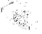
图1是本发明一较好实施例的结构概略图;Fig. 1 is a schematic structural view of a preferred embodiment of the present invention;
图2是本发明一较好实施例的卡盒装置的分解结构斜视图:Fig. 2 is the exploded perspective view of the cartridge device of a preferred embodiment of the present invention:
图3是图、2的组装斜视图;Fig. 3 is the assembled oblique view of Fig. 2;
图4是墨水喷射单元IJU安装部的斜视图;Fig. 4 is a perspective view of the installation part of the ink jet unit IJU;
图5是卡盒IJC装置的安装说明图;Figure 5 is an illustration of the installation of the cartridge IJC device;
图6是本发明的较好实施例的外观图;Fig. 6 is the exterior view of preferred embodiment of the present invention;
图7是记录头的斜视图;Figure 7 is a perspective view of the recording head;
图8是图7装置的剖面图;Fig. 8 is the sectional view of Fig. 7 device;
图9是另一种记录头结构的剖面图;Fig. 9 is a sectional view of another recording head structure;
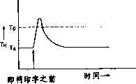
图10是仅在印字之前进行温度调节时记录头的温度变化特性;Fig. 10 is the temperature change characteristic of the recording head when the temperature is adjusted only before printing;
图11及图17为仅在印字过程中进行温度调节时,记录头的温度变化特性;Figure 11 and Figure 17 are the temperature variation characteristics of the recording head when the temperature is adjusted only during the printing process;
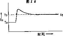
图12及图18为仅在印字之前和印字过程中进行温度调节时,记录头的温度变化特性;Figure 12 and Figure 18 are the temperature variation characteristics of the recording head only when the temperature is adjusted before and during the printing process;
图13表示不进行温度调节而仅在印字时的记录头温度变化特性;Figure 13 shows the temperature change characteristics of the recording head only when printing without temperature adjustment;
图14为用本发明第1实施例进行印字时,记录头的温度变化特性;Figure 14 is the temperature change characteristic of the recording head when printing with the first embodiment of the present invention;
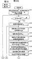
图15是本发明第1实施例的温度控制流程图:Fig. 15 is the temperature control flowchart of the first embodiment of the present invention:
图16是记录头的温升特性图;Fig. 16 is a temperature rise characteristic diagram of a recording head;
图19为本发明第2实施例在印字时记录头的温度变化特性:Fig. 19 is the temperature change characteristic of the recording head when printing in the second embodiment of the present invention:
图20是本发明第2实施例的温度控制流程图:Fig. 20 is the temperature control flowchart of the 2nd embodiment of the present invention:
图21是本发明一较好实施例的控制部分的结构示意方框图;Fig. 21 is a structural schematic block diagram of the control part of a preferred embodiment of the present invention;
图22、图23和图25是温度传感器附近的机内温度种记录头温度的变化特性;Fig. 22, Fig. 23 and Fig. 25 are the change characteristics of the temperature of the recording head near the temperature sensor;
图24为本发明第3实施例的温度控制流程图;Fig. 24 is the temperature control flowchart of the 3rd embodiment of the present invention;
图26是温度传感器附近的机内温度和修正温度的变化特性图;Fig. 26 is a change characteristic diagram of the temperature in the machine near the temperature sensor and the corrected temperature;
图27是温度调节定时的时间图;Fig. 27 is a timing diagram of temperature adjustment timing;
图28是说明调温脉冲输出定时的时间图:Fig. 28 is a time chart illustrating the timing of the temperature regulation pulse output:
图29是本发明第4实施例的温度控制流程图;Fig. 29 is the temperature control flowchart of the 4th embodiment of the present invention;
图30是对应各印字比率的记录头平衡温度特性图;Fig. 30 is a characteristic diagram of the balance temperature of the recording head corresponding to each printing ratio;
图31是对应各印字比率的记录头升温及降温的特性图;Fig. 31 is a characteristic diagram of heating and cooling of the recording head corresponding to each printing ratio;
图32和图33是本发明第5实施例的温度控制流程图;Fig. 32 and Fig. 33 are the temperature control flowchart of the 5th embodiment of the present invention;
图34是本发明第6实施例进行温度控制的墨水喷射记录装置模式的斜视图;Fig. 34 is a schematic perspective view of a temperature-controlled inkjet recording device according to a sixth embodiment of the present invention;
图35是图34中记录头构造模式的局部斜视图;Fig. 35 is a partial oblique view of the construction mode of the recording head in Fig. 34;
图36是表示图34中的记录头温度和喷出用加热器的驱动用功率晶体管温度之间的关系的曲线图;Fig. 36 is a graph showing the relationship between the temperature of the recording head in Fig. 34 and the temperature of the power transistor for driving the ejection heater;
图37是图34中记录头的温控系统的方框图;Fig. 37 is a block diagram of the temperature control system of the recording head in Fig. 34;
图38是本发明第7实施例中所给出的具有温度控制的记录头的结构模式的部分斜视图;Fig. 38 is a partial oblique view of a structural model of a recording head with temperature control given in a seventh embodiment of the present invention;
图39是本发明第7实施例中的印刷电路基板的剖面图;39 is a cross-sectional view of a printed circuit board in a seventh embodiment of the present invention;
图40是本发明第7实施例的温控系统的方框图;Fig. 40 is a block diagram of the temperature control system of the seventh embodiment of the present invention;
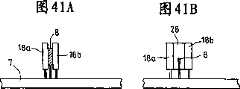
图41是本发明第8实施例的印刷电路基板的剖面图;41 is a cross-sectional view of a printed circuit board according to an eighth embodiment of the present invention;
图42是本发明的第9实施例的印刷电路基板的剖面图;42 is a cross-sectional view of a printed circuit board according to a ninth embodiment of the present invention;
图43是本发明第9实施例的控制系统的方框图。Fig. 43 is a block diagram of a control system according to a ninth embodiment of the present invention.
图2至图6、是为说明实施本发明或所用较好的墨水喷射单元IJU、墨水喷射记录头IJH、墨水容器IT、墨水喷射卡盒IJC、墨水喷射记录装置主机IJRA、滑架HC它们之间关系的说明图。以下将用上述这些图对各部分的结构进行说明。Fig. 2 to Fig. 6, is to illustrate the embodiment of the present invention or used better inkjet unit IJU, inkjet recording head IJH, ink container IT, inkjet cartridge IJC, inkjet recording device host IJRA, carriage HC among them An illustration of the relationship between. The structure of each part will be described below using the above-mentioned figures.
本实施例中的墨水喷射卡盒IJC、如图3的斜视图所示,因收容墨水部分的比例很大,墨水喷射单元IJU的前端做成从墨水容器IT的前面略微向前突出的形状。该墨水喷射卡盒IJC,是由装载在墨水喷射记录装置主机IJRA上的滑架HC(图5)的定位装置(下面说明)和电气接点所固定支撑的,而且是可以相对滑架HC进行拆装的一种可拆装式结构。本例中的图2至图6是本发明成立阶段的各个发明所适用的结构,因此,在简单地说明这些发明的结构的同时,对装置的整体也予以说明。In the ink jet cartridge IJC in this embodiment, as shown in the perspective view of FIG. 3 , the ink jet unit IJU has a front end slightly protruding forward from the front of the ink tank IT because the proportion of the portion containing ink is large. The ink jet cartridge IJC is fixedly supported by the positioning device (described below) and electrical contacts of the carriage HC (Fig. 5) mounted on the main body IJRA of the ink jet recording device, and can be disassembled relative to the carriage HC. A detachable structure. Fig. 2 to Fig. 6 in this example show the structures to which the respective inventions in the stage of establishment of the present invention are applied. Therefore, while briefly describing the structures of these inventions, the whole apparatus will also be described.
(i)关于墨水喷射单元IJU结构的说明。(i) Description about the structure of the ink ejection unit IJU.
墨水喷射单元IJU是发泡喷射方式的单元,其利用电热变换体按照电信号所生成的热量,使墨水产生膜沸腾并进行记录。The ink jetting unit IJU is a unit of a foam jetting method, and performs recording by causing film boiling of ink by using heat generated by an electrothermal transducer according to an electric signal.
图2中,100是加热器板,其是由用成膜技术在硅基片上形成多排形状配布的电热变换体(喷出加热器)、调温用加热器以及对它们供电的铝配电线构成的。In Fig. 2, 100 is a heater plate, which is formed on a silicon substrate by film-forming technology in multiple rows of electrothermal transformation bodies (spray heaters), heaters for temperature adjustment, and aluminum power distribution boards that supply power to them. made of lines.
200是与加热板100相对应的配线底板,其有和加热板100的配线相对应的配线(例如用引线接合法连接),并且在这些配线的端部,有接受从主机装置来的电信号的焊接点凸起201。200 is a wiring board corresponding to the
1300是装有把各个墨水通路分隔开的隔板和共用液室的带沟槽的顶板,其是和墨水注入口1500及具有多个喷出口的孔板400呈整体型的,1500是把墨水容器提供的墨水导入到共用液室的注入口。作为整体成型的材料,最好是采用聚砜,其它成型用树脂也可以。1300 is a grooved top plate equipped with partitions separating each ink passage and a common liquid chamber, which is integral with the
300是对配线基板200背面予以平面支撑的支撑体,例如是金属制的支撑体,并作为墨水喷射单元的底板。300 is a support for planarly supporting the back surface of the
500是M字形状的压簧,其M状的中央部分,轻轻地压住共用液室,同时以其挡板部分501用线压将液路的一部分压住。压簧的爪脚通过支撑体300的孔3121,将加热器板100和顶板1300固定在支撑体300的背面,使它们呈钳入状态而结合起来,利用压簧500及其挡板部分501的弹性势能,将加热器板100和顶板1300压接固定。另外在支撑体300上,还有定位孔312,1900,2000,它们分别与两个对墨水容器IT定位用的凸起1012,以及热熔按固定用的定位凸起1800和1801相配合。此外,在支撑体300的背面还有装置主机IJRA的滑架HC定位用的凸起2500、2600。500 is an M-shaped stage clip, and its M-shaped central part gently presses the common liquid chamber, and simultaneously presses a part of the liquid path with its
支撑体300还有一个可使墨水供给管2200(后述)穿过的孔320,墨水供应管2200可供给来自墨水容器的墨水。配线基板200与支撑体300的固定,是用粘接剂粘接的。支撑体300上的凹部2400,2400,分别设在定位凸起2500及2600的附近,并位于平行槽沟3000和3001的多条延长线上,槽沟3000和3001设置在已组装了的墨水喷射卡盒IJC(图3)中记录头前端的周围三边平面上。因此,沿平行槽沟3000、3001移来的脏物和墨水等,将不致落到突起2500、2600上。The
槽沟3000上的盖部件800,如图3所示,其形成墨水喷射卡盒IJC的外壁,同时,与墨水容器IT共同形成容纳墨水喷射单元IJU的空间部分。The
由平行槽沟3001形成的墨水供应部件600,其固定于前述墨水供应管2200一侧形成的外伸臂上,使墨水导管1600与墨水供应管2200相连接,且为确保墨水导管1600的固定部与墨水供应管2200的毛细现象,在部件600中插入了密封栓602。另外,601是实施墨水容器IT和供应管2200密封结合的密封件,700是设置在供应管容器侧端部的过滤器。The
上述墨水供给部件600,是模压成型的,因而不仅价廉、定位精度高,而且不会产生制作方面的精度降低。由于墨水导管1600采用了外伸臂结构,可使导管1600相对于上述注入口1500形成稳定的压紧状态,所以部件600更适于大量生产。The above-mentioned
在本例中,在这种压紧状态下,密封粘接剂从墨水供给部一侧流入,可确保得到比较完全的连通状态。In this example, in this pressed state, the sealing adhesive flows in from the ink supply part side, and a relatively complete communication state can be ensured.
另外,墨水供给部件600相对支撑体300的固定,是使供应构件600背面的销子,(该销子与支撑体300的孔1901、1902相对应)穿过支撑体300的孔1901、1902,并使其突出出来,然后将突出于支撑体300背面的部分加以简单的热熔而完成的。由热熔后在背面所形成的略微突出的部分,被收纳在墨水容器的墨水喷射单元IJU安装侧面的凹坑(未画出)处,因而可使单元IJU具有正确的定位面。In addition, the fixation of the
(ii)关于墨水容器IT的结构说明(ii) Description of the structure of the ink tank IT
墨水容器是由卡盒本体1000、墨水吸收体900、盖部件1100构成的,其中吸收体900从卡盒本体的上述单元IJU安装面的相对测面插入之后,再将其用密封的盖部件1100盖住。The ink container is composed of a
900是用来浸含墨水的吸收体,设置在卡盒本体1000之内。1200是墨水供应口,对上述100-600各构件所组成的单元IJU供给墨水,同时在把上述单元IJU装配到卡盒本体1000的1010部位之前,由供给口1200注入墨水并使吸收体900浸含墨水,所以也是注入口。900 is an absorber for impregnating ink, which is set inside the
在本实施例中,可以供给墨水的部位是大气连通口1401及供应口1200。为使来自墨水容器的墨水能良好地进行供给,在本体1000上,设置了棱2300,在盖构件1100上设置了棱2301、2302,并由它们形成存留空气的空间,这一空间从大气连通口1401侧开始,延续到距墨水供应口1200最远的角部处,从供应口1200一侧向吸收体均匀而良好地供给墨水是很重要的,因此上述方式在实用中极有效。In the present embodiment, the places where ink can be supplied are the
棱2300设置在墨水容器本体1000的后面,其包括与滑架移动方向相平行的四条棱,用来防止吸收体紧贴到后面部分的表面上。部分棱2301和2302与棱2300延长部分相对应,被设置在盖构件1100的内面,并与2300形成不同的分割状态,以增大存留空气的空间。而且部分棱2301、2302分散地设置于盖部件1100整个面积的一半以下的面积上。借助这些棱,在毛细管力作用下,能确实地把吸收体的离墨水供应口1200最远的角部处的墨水平稳地引导到供应口1200侧。The
1401是设置在盖部件上的使卡盒内部与大气连通的大气连通口,1400是1401内设置的收容液体材料部件,用以防止从大气连通口泄漏墨水。1401 is an air communication port provided on the cover member to communicate the inside of the cartridge with the atmosphere, and 1400 is a liquid material storage part arranged in 1401 to prevent ink from leaking from the air communication port.
上述墨水容器IT的墨水收容空间是长方体形,当它的长边位于侧面时,上述棱的效果就更好。当收容空间的长边位于滑架移动平行方向上,或其为立方体时,由于在盖构件1100的整个面积上设置了棱,可使吸收体900的墨水稳定地进行供给。为使在有限的空间内尽可能地收容墨水,立方体较适宜。而为了使所收容的墨水不浪费地用于记录,如上所述,在靠近容器角部附近的两个面上,设置上述作用的棱是很重要的。The ink containing space of the above-mentioned ink container IT is in the shape of a cuboid, and when its long side is on the side, the effect of the above-mentioned edge is better. When the long side of the storage space is located parallel to the direction in which the carriage moves, or it is a cube, since the ribs are provided over the entire area of the
本实施例中,墨水容器IT内面的棱2301、2302、是相对矩形体形状的墨水吸收体900的厚度方向均匀配置的,这种结构相对于吸收体整体的墨水消费来说,可以使大气压分布均匀,且几乎没有墨水残留,因而是重要结构。In this embodiment, the
另外,如果详细说明设计这些棱配置的技术思想的话,即,在矩形体四角形的上面,以墨水容器的墨水供应口1200的投影点为园心,并以长边为半径画园弧,对处于园弧之外的吸收体,为了使其能早期达到大气压状态,在园弧的外侧设置所述的棱是很重要的。此时,如果容器的大气连通口1401位于可将大气导入的棱配置的范围内,则可不受本例情况的限制。In addition, if the technical idea of designing these edge configurations in detail, that is, on the quadrangle of the rectangular body, take the projection point of the
在本例中,使墨水喷射卡盒IJC记录头的后面呈平面状,这种构成不但使装置组装时所需的空间最小化,而且也可使墨水的收容量最大化,这样的结构不仅达到了使装置小型化的目的,还具有减少卡盒的更换频度的优点。再加上墨水喷射单元IJU作成了整体,其空间的后方部分就可以被利用,在那儿形成大气连通口1401的突出部分,把该突出部的内部做成空的,因而形成了向前述吸收体900整个厚度中供给大气压的空间1402。按这样的构成就可以提供前所未有的优质卡盒。In this example, the back of the inkjet cartridge IJC recording head is made flat. This structure not only minimizes the space required for device assembly, but also maximizes the ink storage capacity. This structure not only achieves For the purpose of downsizing the device, there is also an advantage of reducing the replacement frequency of the cartridge. In addition, the ink ejection unit IJU is integrated, and the rear part of its space can be utilized to form the protruding part of the
上述的大气压供给空间1402,不仅比以往的空间大,而且由于大气连通口1401位于上方,当出现任何异常情况时,即使墨水已与吸收体脱离,该大气压供给空间1402也可将墨水保留一段时间,从而确保其被吸收体回收,所以可以提供不浪费墨水的卡盒。The above-mentioned atmospheric
墨水容器IT的上述单元IJU的安装面的结构如图4所示,L1是一条几乎通过孔板400突出口中心的与墨水容器IT的底面或滑架的承载基准面相平行的直线。与支撑体300的孔312结合的2个定位凸起1012位于L1直线上。该凸起的高度比支撑体300的厚度略低些,用以对支撑体300进行定位。The structure of the mounting surface of the unit IJU of the ink container IT is shown in Figure 4, L1 is a straight line almost passing through the center of the
在图面中直线L1的延长线上,与滑架定位用的挂钩4001的90°角结合面4002结合的棘爪2100,使滑架定位作用力作用在包含该直线L1的并与上述基准面平行的平面内。On the extension line of the straight lineL1 in the figure, the
如后面图5的说明所述,由于这些原因使得墨水容器本身的定位和记录头喷出口的定位具有同样的精度,因而成为一种效果良好的结构。As described later in the description of FIG. 5, for these reasons, the positioning of the ink container itself and the positioning of the ejection ports of the recording head have the same accuracy, which is an effective structure.
墨水容器的突出部1800、1801分别与支撑体300上的向着墨水容器侧面的固定孔1900、2000对应,而且其比上述突起1012稍长,从而将支撑体300固定到该侧面上。L3是与直线L1相垂直并通过突起部1800的直线,L2是与直线L1相垂直并通过突起部1801的直线。由于上述供给口1200的中心位于直线L3上,因此使得供给口1200和供给管2200的结合状态稳定,还能减轻因落下、和冲击对其结合状态的负荷,因此是所希望的结构。如果直线L2、L3不一致,因在记录头IJH的喷出口侧的凸起1012的周边上有突起1800、1801,所以对记录头的IJH的容器的定位产生增强的效果。用L4表示的曲线,是安装墨水供应部件600时的外壁位置。由于突起1800、1801是沿着该曲线L4的,因而相对于记录头前端结构的重量来说,也是具有足够强度和位置精度的。The
2700是墨水容器IT前边的凸肩,其插到滑架HC的前板400的孔里,它是为墨水容器产生极不利的异变位移时设置的。2101是滑架HC的挡杆,位于滑架HC的一个棒(未画出)附近,并在卡盒IJC的回旋安装位置处插到该棒的下方,如后面所述,且即使有向上的、使滑架从定位的位置脱开的突加力的作用,该保护用构件2101也能使其维持安装状态。2700 is the shoulder on the front side of the ink container IT, which is inserted into the hole of the
墨水容器IT,在单元IJU被安装后,用盖800盖住,除下方开口外,形成包围单元IJU的形状。对于墨水喷射卡盒IJC,因其装载在滑架HC上,其下方开口和滑架HC靠近,所以实质上形成四面被包围的空间。由于该包围空间内的记录头IJH的发热,因此该空间已成为一个有效的保温空间,对长期连续的使用,就会有稍稍的温升,为此,在本例中为了有助于支撑体的自然散热,在卡盒IJC的上部,设有长度小于上述空间长的狭缝1700,其可以防止温升,同时可使单元IJU全部的温度分布均匀而不受环境的影响。The ink tank IT, after the unit IJU is mounted, is covered with a
当墨水喷射卡盒IJC被组装起来之后,墨水从卡盒内部经供给口1200、设在支撑体上的孔320以及设在供给容器600背面的导入口向供给容器600里供给墨水,墨水通过其内部后,再通过一个适当的供给管以及带槽沟顶板1300的墨水导入口1500,流向共用液室。在上述墨水通路的连接部分,配置了诸如硅橡胶或异丁橡胶等密封零件,用以进行密封,以确保墨水通路的供给。After the inkjet cartridge IJC is assembled, the ink is supplied to the
在本例中,顶板1300是用有良好耐墨水性能的聚硫化物、聚醚硫酸酯、聚二苯醚、聚丙烯等的树脂,其与孔板400一起放到金属模具中,并同时进行整体成型。In this example, the
上述那样的整体成型另件,作成墨水供给构件600、顶板1300,孔板400的整体构件和墨水容器本体1000,其不仅使组装的精度达到高水平,而且也极有效地提高了大批生产的产品质量。零件件数比以住可能减少,所以确实可以发挥出所期望的特性。The above-mentioned integral molding parts are made into the
本例上述组装后的形状,如图2-图4所示,墨水供给零件600,其上面部分603和墨水容器IT带有狭缝1700的容器顶部的端部4008之间,形成了如图3所示的狭缝S,其下面部604和墨水容器IT下方的连接着盖800的薄板构件的记录头的侧面端部4011之间,形成和上述狭缝S相同的狭缝(未画出)。这些墨水容器IT和墨水供应构件600之间的狭缝,实际上更促进了狭缝1700的散热作用,而且即使对墨水容器施加了不必要的压力,也可以防止把这些压力波及到墨水喷射单元IJU。The above-mentioned assembled shape of this example, as shown in FIGS. As shown in the slit S, the same slit (not shown) as the above-mentioned slit S is formed between the
总之,本实施例的上述结构,是从前所未有过的结构,其各自都有单独的效果,组合起来也是各构成要素的有机的结构组合。In a word, the above-mentioned structure of this embodiment is an unprecedented structure, each of which has an independent effect, and the combination is also an organic structural combination of the constituent elements.
(iii)墨水喷射卡盒IJC相对滑架HC的安装说明(iii) Installation Instructions for Ink Jet Cartridge IJC Relative to Carriage HC
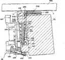
第5图中,5000是压纸卷筒辊,它把记录媒体P从纸面的下方向上方导向。滑架HC沿压纸卷筒移动。为此在滑架HC的前面的压纸卷筒侧,设置了In Fig. 5, 5000 is a platen roller which guides the recording medium P from the bottom to the top of the sheet. The carriage HC moves along the platen. For this purpose, on the platen side in front of the carriage HC, a
挡板4000(厚度为2mm),其位于墨水喷射卡盒IJC的前面;Bezel 4000 (thickness 2mm), which is located in front of the ink jet cartridge IJC;
带有凸缘2011的挠性薄板4005,其上的凸缘2011与卡盒IJC的配线基板200上的凸缘201相对应;A flexible
电气接线支架板4003,用于固定橡胶垫片4007 ,该橡胶垫片所产生的弹性力,从薄板4005的背面将凸缘2011压紧;The electrical
定位钩4001,用于将墨水喷射卡盒IJC固定在记录位置。The
挡板4000上具有两个定位突出面4010,它们与卡盒的支撑体300上的前述定位突起2500、2600分别对应。卡盒安装后,该突出面4010受重直力的作用,因此,在挡板4000前面压纸卷筒一侧,设置了多个朝着该垂直作用力方向的加强筋(图未示出)。这些加强筋从卡盒IJC安装时的前面位置L5略微向压纸卷筒一侧突出(约0.1mm),从而形成记录头的保护突出部。The
电气接线支架板4003设置有多个加强筋4004,它们与前述加强筋方向相垂直,而且从压纸卷筒一侧到定位钩4001一侧,它们的突出长度按比例逐渐减小。这样,就可使卡盒在安装时呈倾斜状态。如图5所示的那样。The electrical
在支架板4003上,为使电气接触状态稳定,备有两个与突出面4010对应的定位面4006,它们位于定位钩一侧,向卡盒施以作用力,其作用力方向与前述两个定位突出面4010对卡盒的作用方向相反。在两个定位面之间形成凸台接触区,同时也统一地确定了与凸缘2011对应的带凸台的橡胶薄板4007的凸台(ボツチ)变形量。这些定位面,将卡盒IJC固定于进行记录的位置,并使其与布线基板200的表面呈接触装态。在本例中,由于布线基板200的凸台201是相对前述直线L1对称分布的,故可使橡胶薄板4007上的各凸台具有一致的变形量,以使凸台2011的接触压力更为稳定。本例中的凸台201的分布为上、下两排,纵两行。On the
固定钩4001其利用一个与固定轴900相配的长孔的移动空间,从图中所示位置向反时针方向回转后,再沿压纸卷筒5000向左侧移动,就能使墨水喷射卡盒IJC相对滑架HC定位。固定钩4001的移动,可采用任何方式,而以用控制杆等结构为最好。总之,当固定钩4001回转时,卡盒IJC就向压纸卷筒侧移动,同时使定位突起2500、2600也向能与挡板的定位面4010相接触的位置移动,靠固定钩4001向左侧移动,使其上的90°挂钩面4002紧贴在卡盒IJC的棘爪2100的90°面上,同时,使卡盒IJC以定位面2500和4010之间的接触区为中心在水平面内转回,最后,凸台201与2011之间相互接触。因此,当固定钩4001在所定位置,即在固定位置被稳定后,就同时达到了下列部件间的接触:凸台201与2011之间呈完全接触、定位面2500与4010之间呈完全接触状态、挂钩90°面4002与卡盒棘爪的90°面相接触,同时形成布线基板200和定位面4007、4008的面接触,从而完成了卡盒IJC在滑架HC上的安装固定。The fixed
(iv)装置主机的简要说明(iv) A brief description of the device host
图6是装载了卡盒的墨水喷射记录装置IJRA的概略图,滑架HC具有固定销(图未示出),其与导引丝杠5005的螺线5004相配合,此丝杠5005是由与驱动马达5013的正反转动连动的驱动力传递齿轮5011、5009带动而转动的。从而使滑架HC在箭头a、b所指方向上来回移动。5002是压纸板,它在滑架移动方向上把纸压向压纸卷筒5000。5007、5008是光电耦合器,为静止位置检测机构,用于确认滑架HC的控制杆5006是否在该区域内,并对马达5013的旋转方向进行切换。5016是盖在记录头前面的盖构件5022的支撑构件,5015是吸引该盖内面的吸引机构,它通过盖内开口5023将记录头吸回原位。5017是清洁刮板,5019是使该清洁刮板5017能前后移动的构件,固定在主机支持板5018上。不言而喻,非上述形状的已知清洁刮板也可用于本例。5021是用于开始吸回的连杆,它随与滑架HC相结合的凸轮5020的移动而移动,驱动马达的驱动力通过离合器等公知机构进行移动控制。Fig. 6 is a schematic view of the ink jet recording apparatus IJRA loaded with a cartridge, the carriage HC has a fixing pin (not shown), which cooperates with a screw 5004 of a lead screw 5005, which is formed by The driving force transmission gears 5011 and 5009 are driven and rotated by the forward and reverse rotation of the driving motor 5013 . Thus, the carriage HC moves back and forth in the directions indicated by arrows a and b. 5002 is a platen, which presses the paper to the
这些加盖、清洁、吸引恢复等是以下述方式构成的,即当滑架HC移到静止位置一侧时,利用导引丝杠5005的作用,使各部件在各自相应的位置进行所要求的操作。但用公知的定时技术使它们进行预期的动作,对本例来说也是适用的。上面所述的各种结构,不论单独的还是组合起来的,都是非常良好的发明,并给出了适用于本发明的良好的结构实施例。These capping, cleaning, suction recovery, etc. are constituted in the following manner, that is, when the carriage HC moves to the side of the rest position, the function of the guide screw 5005 is used to make each component perform the required operation in its corresponding position. operate. But using well-known timing techniques to make them perform the desired actions is also suitable for this example. The various structures described above, individually and in combination, are very well invented and give examples of good structures suitable for use in the present invention.
下面将利用图1及图7之后的各图对适用于上述图2至图6的本发明进行详细的说明。The present invention applied to the above-mentioned Fig. 2 to Fig. 6 will be described in detail below using Fig. 1 and Fig. 7 and subsequent figures.
图1、图7至图15,以及表1和表2,所示的是本发明的第1实施例。图1中,1是墨水容器IT,2是与墨水容器结合的记录头IJH,如图7所示,把墨水容器1和记录头2作成整体型而构成一可拆卸式的卡盒,3是将该卡盒安装在打印机主机上的滑架HC,4是对该滑架,在副扫描方向上进行扫描的导向件,5是压纸卷筒,用以使被印字物(以P表示)沿主扫描方向扫描,6是把经滑架3的驱动记录头2的脉冲电流信号和调温电流传输的挠性电缆,7是印刷电路板,具有控制打印机的电气回路,8是测定其中环境温度的传感器。图7表示一可拆卸式卡盒,9是喷出墨水滴用的喷咀。What Fig. 1, Fig. 7 to Fig. 15, and Table 1 and Table 2 show is the first embodiment of the present invention. Among Fig. 1, 1 is ink container IT, and 2 is the recording head IJH that combines with ink container, as shown in Figure 7,
图8是记录头2的细部说明图,在支撑体300上设有用半导体制造工艺制成的加热器板100,在该加热器板100上又设有按同一半导体制造工艺形成的、对记录头2进行保温、调温的温度调节用加热器(升温用加热器)10。200是设在前述支撑体300上的配线基板,该配线基板200、调温加热器10以及喷出用加热器13按引线接合法进行配线(图中未示配线)。把调温加热器10和加热器板100按其他加工方法贴附于支撑体300上,如图9所示。8 is a detailed explanatory view of the
14是喷出用加热器13加热而产生的汽泡,15是喷出的液滴,12是共用液室,用来使喷出用的墨水流入记录头内。14 is a bubble generated by heating with the
下面对实施例1的开环温度控制的概况作一说明。The outline of the open-loop temperature control in
在此实施例中,为将记录头温度控制在根据印字浓淡等喷出特征而定的目标温度处,进行了印字前的温度调节和印字过程中的温度调节。印字前的调温,是指根据前次印字所经过的时间(等待时间、非印字时间)和当时的环境温度而确定调温加热器的加热量,并在即将印字之前进行加热。印字过程中的加热是根据印字经过的时间和当时的环境温度来确定加热量,并在印字过程中进行加热。另外,所谓印字过程中,不单是指实际进行印字的瞬间(印字用加热器的加热期间),还包含为进行印字的一系列动作时间,如滑架的加速、减速期间,双方向印字时所需的回程时间等。In this embodiment, the temperature adjustment before printing and the temperature adjustment during printing are carried out in order to control the temperature of the recording head to a target temperature determined according to the ejection characteristics such as the density of printing. The temperature adjustment before printing refers to determining the heating amount of the temperature adjustment heater according to the elapsed time of the previous printing (waiting time, non-printing time) and the ambient temperature at that time, and heating it immediately before printing. The heating during the printing process is to determine the amount of heating according to the elapsed time of printing and the ambient temperature at that time, and heat during the printing process. In addition, the so-called printing process does not only refer to the moment of actual printing (heating period of the printing heater), but also includes a series of operation times for printing, such as the period of acceleration and deceleration of the carriage, and printing in both directions. required return time etc.
表1.印字前调温数据表
表2印字过程中调温数据表
表1和表2给出了前述印字前调温和印字过程中调温时所用控制参量的数据表,其存贮在ROM之中。各表中,100%表示投入能量最大,0%表示未投入能量。在本实施例中,是以调温加热器的通电时间(加热脉冲的宽度)来控制能量投入量,在印字前调温,最长时间约6秒,对印字过程中调温,约120毫秒。另外,根据需要的通电时间用通电电压来控制能量投入量也可以,通电时间与通电电压两者同时利用也可以。Table 1 and Table 2 provide the data tables of the control parameters used in the temperature adjustment before printing and during the printing process, which are stored in the ROM. In each table, 100% means that the input energy is maximum, and 0% means that no energy is input. In this embodiment, the amount of energy input is controlled by the power-on time (width of the heating pulse) of the temperature-adjusting heater. The temperature is adjusted before printing, and the maximum time is about 6 seconds. The temperature is adjusted during the printing process, about 120 milliseconds . In addition, the energy input amount may be controlled by the energization voltage according to the required energization time, or both the energization time and the energization voltage may be used simultaneously.
不论印字之前的调温还是印字过程中的调温,环境温度越低,所需升温量就越大,以使温度接近目标温度,因此需要设定较大的能量投入量。此外,当印字之前调温时,等待时间越长,考虑到记录头的散热,就越应设定较大的能量投入量,以使记录头温度接近目标温度。另一方面,在印字过程中调温时,考虑到印字时间越长,记录头就会因蓄热而升温,因此应设定较小的能量投入量。Regardless of the temperature adjustment before printing or during the printing process, the lower the ambient temperature, the greater the amount of temperature increase required to make the temperature close to the target temperature, so it is necessary to set a larger amount of energy input. In addition, when the temperature is adjusted before printing, the longer the waiting time, the greater the energy input should be set in consideration of the heat dissipation of the recording head, so that the temperature of the recording head is close to the target temperature. On the other hand, when adjusting the temperature during the printing process, considering that the longer the printing time, the recording head will heat up due to heat storage, so a smaller energy input should be set.
根据以上所进行的温度控制,即使不采用以往的闭环式控制,也可使记录头的温度控制在目标温度。下面,对温度控制加以详细说明。According to the above-mentioned temperature control, the temperature of the recording head can be controlled to the target temperature without using the conventional closed-loop control. Next, the temperature control will be described in detail.
图10表示的是,当只进行所述印字之前调温操作时,环境温度TA和实际的记录头温度TH相对目标温度TO的变化。图11给出了当只进行所述印字过程中的调温时,记录头温度TH相对目标温度的变化。Fig. 10 shows changes in ambient temperature TA and actual recording head temperature TH relative to target temperature TO when only the pre-printing temperature adjustment operation is performed. Fig. 11 shows the variation of the recording head temperatureTH with respect to the target temperature when only the temperature adjustment during the printing process is performed.
图12给出了当进行印字之前及印字过程中的两种调温时,记录头的温度变化。Figure 12 shows the temperature change of the recording head when two temperature adjustments are performed before printing and during printing.
图13给出不进行调温时,在只有印字本身进行的过程中因自升温而引起的记录头的温度变化。Fig. 13 shows the temperature change of the recording head due to the self-heating during the process of printing itself when the temperature adjustment is not performed.
图14是进行了印字前及印字过程中调温后,印字时的记录头温度变化的一个例子。在60秒和360秒处所出现的记录头的温度(TH)的切换,是因为表2的印字过程中调温数据表中的数据(调温参量)发生变化的缘故。FIG. 14 is an example of the temperature change of the recording head during printing after temperature adjustment before printing and during printing. The switching of the recording head temperature (TH ) at 60 seconds and 360 seconds is due to the change of the data (temperature regulation parameters) in the temperature regulation data table during the printing process shown in Table 2.
第11、12图中的热平衡点温度(TE),表示的是只用调温供给的能量,根据记录头的热容量而自然达到的温度,是由表1、表2的数据决定的。此外将热平衡点温度设定为略低于目标温度,是由于考虑了如图13所示那样的记录头自身加热的升温(自升温),而当把此温升加热到热平衡点的温度上,就可以达到目标温度的缘故。The thermal equilibrium point temperature (TE ) in Figures 11 and 12 indicates the temperature that is naturally reached by the heat capacity of the recording head only with the energy supplied by temperature regulation, and is determined by the data in Table 1 and Table 2. In addition, setting the thermal equilibrium point temperature slightly lower than the target temperature is due to consideration of the temperature rise (self-heating) of the recording head itself as shown in Figure 13, and when this temperature rise is heated to the temperature of the thermal equilibrium point, to reach the target temperature.
以下对本发明第1实施例的温度控制,参照图15的流程图进行说明,根据所述温度控制而产生的记录头的温度变化状态,与图14的曲线对应。The temperature control in the first embodiment of the present invention will be described below with reference to the flow chart in FIG.
当电源投入时,首先程序步S101将等待时间计数器和印字时间计数器复位到0,使控制参量初始化。然后,在程序步S102等待,直到印字信号输入。如果有印字信号输入时,在程序步S103读取主机侧的印刷电路板7上的温度传感器8的环境温度。然后,在程序步S104读取等待时间计数器的等待时间,在电源投入之前,如前所述,这些都复位为0。之后,在程序步S105,根据环境温度等待时间计数器的等待时间参照印字前调温数据表(表1)。由于电源刚投入时,没有因印字而产生温升,所以记录头温度与室温相同,因此,按表中的输出,其能量应该是0-100%,与其他的等待时间相比,要给出较大的输出。随后,在程序步S106,根据该输出数据,对图8中所示的调温加热器10进行加热,使记录头的喷出咀9和共用液室12升温。在本实施例中,环境温度越低,升温量越大,所以其按变大且变长来进行设定。When the power is turned on, firstly the program step S101 resets the waiting time counter and the printing time counter to 0 to initialize the control parameters. Then, it waits at step S102 until a printing signal is input. If there is a printing signal input, the ambient temperature of the
通电完了之后,等待1秒钟左右就开始印字,这时即使记录头内极不均匀的温度分布发生扩散也没关系,在该时间点,程序部S107对等待时间计数器进行复位。After the power is turned on, wait for about 1 second and start printing. At this time, even if the extremely uneven temperature distribution in the recording head spreads, it does not matter. At this point in time, the program section S107 resets the waiting time counter.
然后,在程序步S108启动时间计数器,程序步S109进行初始一行的印字。Then, start the time counter at program step S108, and program step S109 carries out the printing of initial one row.
程序步S110进行时间计数器的印字时间的读取,根据环境温度程序步S111将此读取值与印字过程中调温数据表(表2)相对照。印字时间计数器在印字开始后,几乎立即就不再进行计数了,所以,根据环境温度,数据输出是0-100%,与其他的计数值相比,应作较大的输出。Program step S110 reads the printing time of the time counter, and compares this read value with the temperature adjustment data table (Table 2) in the printing process according to the ambient temperature program step S111. The printing time counter stops counting almost immediately after the printing starts, so the data output is 0-100% according to the ambient temperature, and should be output larger than other count values.
然后,根据印字信号的内容对上面的数据进行调温条件的修正。首先,程序步S112、S113在换行(LF)时进行修正。因换行时不产生印字自升温,若不进行调温而连续进行换行,则记录头的温度会急剧下降。另外,又因换行所需时间极短,如果按上述输出数据而不进行任何修正的话,则单位时间的能量投入量就会过大。Then, according to the content of the printing signal, the temperature adjustment condition is corrected for the above data. Firstly, program steps S112 and S113 are corrected when line feed (LF). Since there is no self-heating during printing, the temperature of the recording head will drop sharply if continuous line feed is performed without temperature adjustment. In addition, because the time required for line-changing is extremely short, if the above-mentioned output data is not modified, the energy input per unit time will be too large.
为此,本实施例给出了修正参量的程序,即对每进行一次换行就向记录头供给原输出数据的十分之一的能量。For this reason, this embodiment provides a procedure for correcting parameters, that is, for each line feed, one-tenth of the energy of the original output data is supplied to the recording head.
此后,程序步S114、S115根据主扫描方向一行的长度进行温度条件的修正。在本实施例中,还采用了在印字可能范围两侧的滑架的加速期间内,对调温加热器进行通电的结构,因此,当滑架移动量小时,单位时间的能量投入量就会过大,为此,提供了一个程序,它可使当滑架的移动量不是全宽时,根据其实际移动量与滑架全宽的比例,给出与之成比例的修正系数。Thereafter, in steps S114 and S115, temperature conditions are corrected according to the length of one line in the main scanning direction. In this embodiment, the temperature-regulating heater is energized during the acceleration period of the carriages on both sides of the printing possible range. Therefore, when the movement amount of the carriage is small, the energy input per unit time will be excessive. Large, for this purpose, a program is provided, which can give a proportional correction coefficient according to the ratio of the actual movement amount to the full width of the carriage when the movement amount of the carriage is not the full width.
用经上述修正了的数据,程序步S116对调温加热器10通电,并进行印字过程中的温度调节,程序步S117再进行一行印字。当印字继续进行时,程序步S118反复读取印字时间计数器。但如前所述,随着印字时间的增大,数据表上的输出数据就会逐渐减小,因而可使投入能量相应地减少。With the above-mentioned corrected data, the program step S116 energizes the temperature-regulating
在一次印字终了时,程序步S119使印字时间计数器复位,同时,程序步S120启动了等待时间计数器,计测下一个印字信号到来之前的时间。When a printing is finished, the program step S119 resets the printing time counter, and at the same time, the program step S120 starts the waiting time counter, and measures the time before the arrival of the next printing signal.
在下一个印字信号到来的时间点,程序步S102至S104读取等待时间计数器和环境温度,根据所读取的等待时间和环境温度,按着印字前调温的数据表格,再次确定输出的能量大小,以后重复进行同样的控制操作。在本实施例中,等待时间计数器可计数到120秒,此后,则假定返回到环境温度而复位为零。At the time when the next printing signal arrives, program steps S102 to S104 read the waiting time counter and ambient temperature, and according to the read waiting time and ambient temperature, according to the data table of temperature adjustment before printing, determine the output energy again , and then repeat the same control operation. In this embodiment, the wait time counter may count up to 120 seconds, after which time it is reset to zero assuming a return to ambient temperature.
在本实施例中,采用了可拆式卡盒型的记录头,但本发明并不限于这种可拆式的结构,采用不更换的永久型的记录头,当然也是有效的。In this embodiment, a detachable cartridge-type recording head is used, but the present invention is not limited to such a detachable structure, and it is of course also effective to use a permanent type recording head that is not replaced.
本实施例中,还采用了印字时间计数器和等待(非印字)时间计数器,以进行印字过程中的调温和印字前调温两种调温,但是,对于台式计算机用的打印机等印字量较少的设备来说,只限于输出字符的打字机其印字打点次数较少,因而由印字本身引起的升温就比图示的要少,所以可根据该装置的输出能量水平,只利用等待(非印字)时间计数器,并且只进行印字之前的温度调节就可以了。另外,如采用插图纸等专用的非印字时间间隔较长的记录装置,用印字时间计数器在印字过程中进行温度调节也可以。In this embodiment, a printing time counter and a waiting (non-printing) time counter are also used to carry out two kinds of temperature adjustments: temperature adjustment in the printing process and temperature adjustment before printing. However, the printing volume of printers such as desktop computers is less As far as equipment is concerned, typewriters that are limited to output characters have fewer printing times, so the temperature rise caused by printing itself is less than that shown in the figure, so according to the output energy level of the device, only waiting (non-printing) can be used Time counter, and only the temperature adjustment before printing is enough. In addition, if a special recording device with a long non-printing time interval is used, such as illustration paper, it is also possible to use a printing time counter to adjust the temperature during the printing process.
为了确定调温用输出能量的大小,除根据印字时间的计数值(等待时间、印字时间)参照数据表所得出的输出数据外,也可以利用其印字前所得到的输出数据的履历。此外,在根据滑架移动量计算出数据的修正系数时,不仅考虑本行的移动量,还应考虑下一行以后的移动量数据。In order to determine the output energy for temperature adjustment, in addition to the output data obtained by referring to the data table based on the count value of printing time (waiting time, printing time), the history of output data obtained before printing can also be used. In addition, when calculating the correction coefficient of the data based on the carriage movement amount, not only the movement amount of the current line but also the movement amount data of the next line and subsequent lines should be considered.
此外,关于记录头的加热装置,可以使用公知技术。印字时间计测也可以印字行数的计数和印字文字数的计数来代替。In addition, as for the heating device of the recording head, known techniques can be used. The printing time measurement may be replaced by counting the number of printed lines and counting the number of printed characters.
如前面所说,采用第1实施例,可以不用象以往那样在记录头上组装进温度传感器,并进行闭环温度控制,而是在打印机等记录装置本机一侧装设环境温度测量装置,并组装进控制软件,该软件按照记录头所具有的热容量而统一决定的加热、冷却特性,来进行温度控制,因而,即使采用开环式温度调节,也可以对记录头的温度按所预期的温度进行控制。As mentioned above, adopt the first embodiment, can not be assembled into temperature sensor on the recording head as in the past, and carry out closed-loop temperature control, but install ambient temperature measuring device on this machine side of recording device such as printer, and Assembled into the control software, the software controls the temperature according to the heating and cooling characteristics uniformly determined by the heat capacity of the recording head. Therefore, even if the open-loop temperature adjustment is used, the temperature of the recording head can be controlled according to the expected temperature. Take control.
尤其是当使用记录头与墨水容器成一体的卡盒式可拆型记录头时,就不需要检测来自记录头的温度传感器的信号电流了,从而解决可拆式记录头的温度控制中的最大缺点,即温度传感器与记录头之间的性能离散问题,因而消除了记录头之间印字性能的离散现象。而得到具有恒定印字质量的记录装置。除此之外,由于从作为消耗品的记录头的卡盒中,废除了温度传感器,因而也免掉了以前一直需要进行的选择温度传感器的工序,或调整温度传感器的工序,从而使成本大幅度降低。又因不用温度传感器,而使成品率大幅地提高,因而能够进一步降低成本。Especially when using the cartridge-type detachable type recording head in which the recording head is integrated with the ink container, it is not necessary to detect the signal current from the temperature sensor of the recording head, thereby solving the maximum problem in the temperature control of the detachable type recording head. Disadvantage, that is, the performance dispersion between the temperature sensor and the recording head, thus eliminating the dispersion of printing performance between the recording heads. A recording device with constant printing quality is obtained. In addition, since the temperature sensor is abolished from the cartridge of the recording head as a consumable, the process of selecting the temperature sensor or adjusting the temperature sensor, which has been required in the past, is also eliminated, resulting in a large cost. The magnitude is reduced. In addition, since the temperature sensor is not used, the yield rate is greatly improved, and thus the cost can be further reduced.
另外,从电气回路方面看,就没有必要再检测记录头来的微弱电流信号了,对于可拆式卡盒从记录装置主机上装拆而使接点暴露的问题、从记录装置主机到记录头的挠性电缆和印刷电路板线路图案的防静电措施等,都可得到简化。In addition, from the perspective of the electrical circuit, there is no need to detect the weak current signal from the recording head. For the problem that the detachable cartridge is assembled and disassembled from the main body of the recording device and the contact is exposed, the flexure from the main body of the recording device to the recording head Anti-static measures for cables and printed circuit board circuit patterns can be simplified.
尤其是上述这点,对小型可携带式记录装置来说,其外壳和电气回路的充分屏蔽等措施就不必要了,所以不但很有效而且还有极大地降低了成本的效果。Especially in the above-mentioned point, measures such as sufficient shielding of the casing and the electric circuit are unnecessary for small portable recording devices, so not only are they effective but also have the effect of greatly reducing the cost.
关于本发明的第2实施例,下面将参照图17至图21以及表3予以说明。A second embodiment of the present invention will be described below with reference to FIGS. 17 to 21 and Table 3. FIG.
第2实施例采用了发泡喷射方式,且随着印字的进行不发热而产生散热的记录方式,使第1实施例的开环得到更进一步的发展,并可以进行充分的温度控制。The second embodiment adopts the foam jetting method, and the recording method of generating heat without generating heat as the printing progresses further develops the open loop of the first embodiment, and can carry out sufficient temperature control.
在第1实施例中,供给记录头的使其升温的能量大小,是根据环境温度、本次印字开始前记录头的印字时间以及非印字时间,对照控制用数据表格来确定的。其结果则可以只利用调整主机侧的温度传感器,就能进行开环温度控制。In the first embodiment, the amount of energy supplied to the recording head to raise the temperature is determined based on the ambient temperature, the printing time and non-printing time of the recording head before the current printing starts, and is determined by referring to the data table for control. As a result, open-loop temperature control can be performed only by adjusting the temperature sensor on the host side.
在以字符为主的打印机中,因字符的印字比率低,其平均印字比率为百分之几到百分之三十,如第1实施例那样,可以使用印字时间、非印字时间等容易从打印机侧测出的操作控制参量。根据主机侧的予测数据进行开环调温,就可以得到充分的温度予测性,并可以调整调温用的能量投入。In a character-based printer, because the printing ratio of characters is low, the average printing ratio is several percent to thirty percent. Operational control parameters measured on the printer side. By performing open-loop temperature regulation based on the predicted data on the host side, sufficient temperature predictability can be obtained, and energy input for temperature regulation can be adjusted.
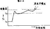
但是,对于以高速图象印字为主的打印机,因平均印字率在百分之几到百分之百之间变化很大,如只用印字时间、非印字时间等操作控制参量,则当调温能量和因高印字比率而发出的热能相选加在一起的情况下,就会如第16图所示那样,容易引起升温过高,并会因不喷出、飞射、喷出量过多等现象而造成印着不良。浓淡不均等不正常喷出的问题就会发生,因而不够完美。However, for printers that mainly use high-speed image printing, because the average printing rate varies greatly from a few percent to 100 percent, if only operating control parameters such as printing time and non-printing time are used, when the temperature regulation energy and When the heat energy emitted due to high printing ratio is selected and added together, as shown in Figure 16, it is easy to cause excessive temperature rise, and there will be phenomena such as no ejection, flying ejection, excessive ejection, etc. And cause poor printing. Problems such as uneven thickness and abnormal ejection will occur, so it is not perfect.
另一方面,为了防止在高印字比率所引起的过升温,在设定一个高的平均印字比率之后,应考虑设定比进行字符印字时要低的热平衡温度。但是若此时是进行印字比率较低的图型式的印字时,由于采用上述开环、印字过程中的调温方式,自升温较小,所以记录头的实际温度也会产生向下漂移,而造成浓度薄和浓淡不均的现象,作为高速图象打印机来说这也是一个不足之处。On the other hand, in order to prevent excessive temperature rise caused by high printing ratio, after setting a high average printing ratio, it should be considered to set a lower heat balance temperature than when printing characters. However, if the printing of graphics with a relatively low printing ratio is carried out at this time, due to the above-mentioned open-loop temperature adjustment method during the printing process, the self-heating is small, so the actual temperature of the recording head will also drift downward, and The phenomenon of thin density and uneven shade is caused, which is also a shortcoming as a high-speed image printer.
当进行高印字比率的图型印字时,在印完一页后,温度就会升得很高,特别是最大临界的过升温完结时,与设定平均印字比率时相比就需要花费冷却时间,为此,在上述开环控制的印字前的调温时,应给出比下一次印字所需的能量更多的升温能量。When performing graphic printing with a high printing ratio, the temperature will rise very high after printing a page, especially when the maximum critical overheating is completed, it will take a cooling time compared with setting the average printing ratio For this reason, during the temperature adjustment before the printing of the above-mentioned open-loop control, more heating energy should be given than the energy required for the next printing.
下面对实施例2的开环温度控制的概略予以说明。The outline of the open-loop temperature control in Example 2 will be described below.
此实施例,基本上同实施例1,进行印字前调温和印字中调温,其特征是,当前次印字完结时,予测记录头的温度,根据该予测温度对印字前调温的能量予以修正。而且其特征还在于,求出每一秒钟的印字比率,根据其平均印字比率,修正印字中的调温能量。通过进行的上述能量修正,即使在进行高印字比率的图案印字时,产生打印图象的情况下,也可以进行适宜的开环温度控制。This embodiment, basically the same as
表3至表5给出了第2实施例中所用的印字前调温、印字中调温、印字比率修正等的控制参量数据。表3和表4分别和第1实施例的表1和表2相对应。Table 3 to Table 5 show the control parameter data of temperature adjustment before printing, temperature adjustment during printing, and printing ratio correction used in the second embodiment. Table 3 and Table 4 respectively correspond to Table 1 and Table 2 of the first embodiment.
表3.印字前调温数据表
表4.印字中调温数据表
表5输出能量修正数据表
图17给出了只进行印字中调温(但进行修正)时,记录头实际温度相对于环境温度和目标温度的变化。关于只进行印字前调温(但进行了修正)时的记录头温度的变化,因与图5所示相同,故而省略了说明。图18给出了进行印字前及印字中两种调温(但进行了修正)时的记录头温度变化。Figure 17 shows the change of the actual temperature of the recording head relative to the ambient temperature and the target temperature when only the temperature adjustment is performed during printing (but corrections are made). The change of the temperature of the recording head when only the temperature adjustment before printing is performed (however, correction is performed) is the same as that shown in FIG. 5 , so the description thereof will be omitted. Figure 18 shows the temperature change of the recording head when two temperature adjustments are performed (but corrected) before printing and during printing.
图19(a)表示的是印字比率变化的一个例子,图19(b)所示,是按照本发明第2实施例进行印字前和印字中调温时,对应于图19(a)所示的印字比率的变化、记录头的温度变化情况,图19(c)给出调温能量操作量的变化。What Fig. 19 (a) shows is an example of the printing ratio change, Fig. 19 (b) shows, when the temperature is adjusted before printing and during printing according to the second embodiment of the present invention, it corresponds to Fig. 19 (a) The change of the printing ratio and the temperature change of the recording head, Fig. 19(c) shows the change of the temperature adjustment energy operation amount.
图17、图18所示的热平衡点温度的设定比第1实施例的图11、图12中所示的设定要高,这是因为在第1实施例中,热平衡点温度的设定考虑了记录头的自加热因素,而在本实施例中,由于在印字中的调温过程中,已进行了修正,所以在设定热平衡点温度时,就不必考虑了。The setting of the thermal equilibrium point temperature shown in Fig. 17 and Fig. 18 is higher than the setting shown in Fig. 11 and Fig. 12 of the first embodiment, this is because in the first embodiment, the setting of the thermal equilibrium point temperature The self-heating factor of the recording head is considered, and in this embodiment, since the correction has been carried out during the temperature adjustment process in printing, it is not necessary to consider it when setting the temperature of the thermal equilibrium point.
因此,本实施例的印字中的调温能量的投入量,比实施例1就要设定得高一些。Therefore, the input amount of the temperature adjustment energy in the printing of the present embodiment is set higher than that of the first embodiment.
下面,对本发明的第2实施例的温度控制将参照图20的流程图予以说明,与该温度控制相应的记录头温度变化情况,如图19所示。Next, the temperature control in the second embodiment of the present invention will be described with reference to the flow chart of FIG.
首先,当电源投入时,把等待时间计数器、印字时间计数器、印字脉冲计数器以及修正系数存储器等复位置“0”(程序步S201),对控制参量进行初始化,并等待直到有印字信号输入(程序步S202)。First, when the power is turned on, reset the waiting time counter, printing time counter, printing pulse counter and correction coefficient memory to "0" (program step S201), initialize the control parameters, and wait until there is a printing signal input (program Step S202).
当有印字信号输入时,读取主机侧印刷电路板7上的用温度传感器8测出的环境温度T(程序步S203)。然后,读取前次印字完结时的予测温度TFINI(后面将详细说明)(程序步S204),再读取等待时间计数器的等待时间tw,并且在此时间点,如前所述将等待时间计数器复位为“0”,之后,根据等待时间tw和环境温度T,参照印字前及印字中调温的数据表(表3、表4)(程序步S205)。When a printing signal is input, the ambient temperature T measured by the
此时,因没有印字的升温,所以与室温相同,由印字前的调温能量Ppreo决定的输出数据,对应于环境温度,应变为0-100%,比其它等待时间的输出值要大。(程序S206)。At this time, because there is no temperature rise for printing, the output data determined by the temperature adjustment energy Ppreo before printing is the same as room temperature, and should be 0-100% corresponding to the ambient temperature, which is larger than the output value for other waiting times. (Procedure S206).
然后,根据输出数据表,计算印字前的调温操作量Ppre=Ppreo×f(TFINI)(程序步S207)其中函数f与前次印字完结时予测的温度TFINI有负的相关关系。根据计算出的操作量Ppre,使图7所示的调温用加热器10加热,而使记录头2的喷咀9和共用液室12升温(程序步S208)。在本实施例中,温度越低,通电的时间就设定的越长。通电完结后,等待约1秒钟,使记录头内形成的极不均匀的温度分布得以扩散。在这个时间点上,对等待时间计数器进行复位(程序步S209),同时启动印字时间计数器(程序步S210)。Then, according to the output data table, calculate the temperature adjustment operation amount before printing Ppre =Ppreo × f(TFINI ) (program step S207), wherein the function f has a negative correlation with the predicted temperature TFINI when the previous printing is completed relation. Based on the calculated operation amount Ppre , the
然后,根据印字信号的内容,对应程序步S206中所得到的印字中初始操作量PLINEO,修正调温条件。Then, according to the content of the printing signal, the temperature adjustment condition is corrected corresponding to the initial operation amount PLINEO during printing obtained in step S206.
首先,按副扫描方向的一行的长度,进行调温条件的修正,和第1实施例中的程序步S114、S115(第15图)同样,算出能量修正系数L,该系数是用来和实际的滑架移动量相对滑架全宽的比成比例的修正系数相乘的。(程序步S211)。First, according to the length of one line in the sub-scanning direction, the correction of the temperature adjustment condition is carried out, the same as the steps S114 and S115 (Fig. 15) in the first embodiment, the energy correction coefficient L is calculated, and this coefficient is used to compare with the actual Multiplied by a correction factor proportional to the ratio of the carriage movement amount relative to the carriage full width. (program step S211).
然后,对需印字的印字内容的一秒期间的喷出脉冲、印字点数进行计数,并算出在该期间的平均印字比率(印字能率)(程序步S212)。Then, the ejection pulses and the number of printing dots during one second of the printing content to be printed are counted, and the average printing ratio (printing efficiency) during this period is calculated (step S212).
接着,根据每秒的平均印字比率,算出输出能量的修正系数P1和P2(程序步S213),其中能量修正系数P1,是低响应的修正系数,是根据在过去的100秒内的每秒平均印字比率所取的平均值,而P2是高响应的能量修正系数,是根据过去10秒内的每秒平均印字比率所取的平均值。该修正系数P1和P2,在任何情况下都可以根据各印字平均比率,参照表5所示的数据表格而得到。Then, according to the average printing rate per second, calculate the correction coefficients P1 and P2 of the output energy (program step S213), wherein the power correction coefficient P1 is a correction coefficient for low response, and is based on the output power in the past 100 seconds The average value of the average printing rate per second, and P2 is the energy correction factor for high response, which is the average value based on the average printing rate per second in the past 10 seconds. In any case, the correction coefficientsP1 andP2 can be obtained by referring to the data table shown in Table 5 based on the average ratio of each printing.
然后根据上述数据,算出印字中调温操作量PLINE,在本实施例中其为:Then, according to the above data, the temperature adjustment operation amount PLINE in printing is calculated, which in this embodiment is:
PLINE=PLINEO×P1×P2×L,(程序步S214)。PLINE =PLINEO ×P1 ×P2 ×L, (step S214).
如前所述,其中PLINEO是印字中调温的初始操作量,修正系数L是前述对滑架移动量的修正系数,所有修正系数都在0和1(0%-100%)之间被标准化了。从上式可知,在低响应或高响应的平均印字比率高并且修正系数P1或P2小的情况下,由于印字中调温操作量PLINE变小,所以可防止印字中调温过程的过升温。之后,与实施例1的程序步S112、S113(图15)同样,对换行(LF)信号进行调温条件修正(程序步S215)。As mentioned above, where PLINEO is the initial operation amount of temperature adjustment in printing, and the correction coefficient L is the correction coefficient for the aforementioned carriage movement amount, and all correction coefficients are between 0 and 1 (0%-100%). standardized. It can be known from the above formula that when the average printing ratio of low response or high response is high and the correction coefficient P1 or P2 is small, since the temperature adjustment operation amount PLINE during printing becomes smaller, it can prevent the temperature adjustment process from overshooting during printing. heat up. After that, similarly to steps S112 and S113 (FIG. 15) of the first embodiment, temperature adjustment condition correction is performed on the line feed (LF) signal (step S215).
为此,制作一修正程序,即每换行一行,就对记录头2供给原来印字中调温操作量PLINE的十分之一能量(程序步S216),以进行修正。For this reason, a correction program is made, that is, every time a line is changed, the
然后,根据这些修正了的数据,对调温加热器通电(程序步S217),并进行一行印字(程序步S218)。此时,启动等待时间计数器(程序步S219),将印字完结时的予测温度TFINI存贮起来(程序步S220),根据能量修正系数P1(低响应)的参数,按下述公式计算印字完结时的予测温度TFINI,Then, according to the corrected data, the temperature adjustment heater is energized (step S217), and one line of printing is performed (step S218). Now, start the waiting time counter (program step S219), store the predicted temperature TFINI when printing is finished (program step S220), and calculate according to the following formula according to the parameter of energy correction coefficientP1 (low response) The estimated temperature TFINI at the end of printing,
TFINI=目标温度×K(0.3+P1)TFINI = target temperature × K (0.3+P1 )
(其中:K是合适的系数)(where: K is the appropriate coefficient)
当(0.3+P1)<1时,则TFINI=目标温度。其结果,当低响应的能量修正系数P1超过0.7的情况下进行长时间连续进行高印字比率印字时,有可能产生超过目标温度的现象,为此,在下次印字开始时,利用等待时间tw计算出印字前调温能量Ppreo,以防止产生误差。When (0.3+P1 )<1, then TFINI = target temperature. As a result, when the low-response energy correction coefficientP1 exceeds 0.7, when continuous high printing ratio printing is performed for a long time, the target temperature may be exceeded. Therefore, when the next printing starts, use the waiting The time tw calculates the temperature adjustment energy Ppreo before printing to prevent errors.
当继续进行印字时,再度重复地进行图20所示的控制操作。这种情况下,等待时间计数器的计数值几乎不增加,因此,如表3所示,对任何环境温度来说,其输出能量都应是0,所以可以不用对每行印字进行印字前温度调整。印字完结时(程序步S222),在下一个印字信号到来的时间点上再重复进行图20所示的控制。When printing is continued, the control operation shown in Fig. 20 is repeated again. In this case, the count value of the waiting time counter hardly increases, so, as shown in Table 3, for any ambient temperature, its output energy should be 0, so it is not necessary to adjust the temperature before printing for each line of printing . When the printing is completed (step S222), the control shown in Fig. 20 is repeated at the time when the next printing signal arrives.
本实施例中,等待时间计数器计数到120秒后,就假定已恢复到环境温度,并复位为零。In this embodiment, after the waiting time counter counts to 120 seconds, it is assumed that the ambient temperature has been recovered, and is reset to zero.
图21表示为执行上述第2实施例的温度控制的控制系统方框图,它也同样适用于实施例1.。Fig. 21 is a block diagram showing a control system for performing the temperature control of the above-mentioned second embodiment, which is also applicable to the first embodiment. .
图21中,20是发出指令信号和印字信号等的计算机的主处理机,21是由等待时间计数器印字时间计算器、印字脉冲计数器等组成的作为计数机构的计数器,8是作为计测环境温度的温度测量机构的传感器,25是记录头的驱动机构,同时作为对记录头加热升温的升温机构。22是作为温度控制机构的控制单元,根据只读存贮器(ROM)24内存贮的程序对一般的墨水喷射记录装置的印字进行控制。此外,控制单元22还根据传感器23和计数器21的各自测量的结果,通过记录头驱动装置25,对记录头2升温的调温能量进行调整。In Fig. 21, 20 is the main processing machine of the computer that sends instruction signal and printing signal etc., 21 is the counter as counting mechanism that is made up of waiting time counter printing time counter, printing pulse counter etc., 8 is as the counter of measuring environment temperature. The sensor of the temperature measuring mechanism, 25 is the driving mechanism of the recording head, simultaneously as the heating mechanism for heating the recording head. 22 is a control unit as a temperature control mechanism, which controls printing of a general inkjet recording device based on a program stored in a read only memory (ROM) 24 . In addition, the control unit 22 also adjusts the temperature adjustment energy for heating the
另外,在本实施例中,是利用印字时间计数器和等待(非印字)时间计数器两者对印字中调温和印字前调温两方进行温度调节,但是,当使用专用的插图纸或非印字时间较长的记录装置时,也可以只用印字计数器和只进行印字中调温的方式。In addition, in this embodiment, both the printing time counter and the waiting (non-printing) time counter are used to adjust the temperature during printing and before printing. However, when using special illustration paper or non-printing time For a longer recording device, it is also possible to use only the printing counter and only perform temperature adjustment during printing.
对于印字时间的测量,可以代之以印字计数、印字字数的计数,此外,也可把一秒的平均印字率的计算作为每一行的平均印字率的计算,至于平均计算方式,也可以采用加权等其他平均方法。For the measurement of printing time, it can be replaced by printing count and counting of the number of printed words. In addition, the calculation of the average printing rate of one second can also be used as the calculation of the average printing rate of each line. As for the average calculation method, weighting can also be used. and other averaging methods.
而且,低响应的平均印字率,也可以在过去100秒期间,对每10秒的平均印字比率取平均来求。在上述实施例中,低响应和高响应的修正数据表,可以是通用的,也可以彼此不同。Furthermore, the average printing rate of low response may be obtained by averaging the average printing rate per 10 seconds in the past 100 seconds. In the above embodiments, the modified data tables for low response and high response may be common or different from each other.
有关印字前调温操作量Ppre,用上修的修正系数P1、P2代替函数f(TEINB)来进行修正也行。Regarding the pre-printing temperature adjustment operation amount Ppre , correction may be performed by using the upward correction coefficients P1 and P2 instead of the function f(TEINB ).
如以上所述,根据第2实施例,由于是按印字比率来控制调温功率的,所以在第1实施例的效果上,又增加了也可以对印字比率变化大的图形打印机实行高精度的温度控制的效果。As mentioned above, according to the second embodiment, since the temperature adjustment power is controlled according to the printing ratio, in addition to the effect of the first embodiment, it is also possible to implement high-precision printing for graphic printers with large variations in the printing ratio. The effect of temperature control.
另外,由于是根据低响应和高响应两者的印字比率控制调温功率的,所以对印字比率缓慢变化的和急剧变化的两种情况都能适用。In addition, since the temperature adjustment power is controlled according to the printing ratios of both low response and high response, it is applicable to both cases where the printing ratio changes slowly and rapidly.
第2实施例是根据低响应和高响应的印字比率控制调温功率,但也可以根据其中的一种。另外还可以求出中等响应的印字比率,根据低中、高响应印字比率也可以。In the second embodiment, the temperature adjustment power is controlled according to the printing ratio of low response and high response, but it may be based on one of them. In addition, the printing rate of medium response can also be calculated, and the printing rate of low, medium and high response can also be obtained.
以下,将参照附图22至图26和表5,说明本发明的第3实施例。Hereinafter, a third embodiment of the present invention will be described with reference to FIGS. 22 to 26 and Table 5. FIG.
在第3实施例中,即便检测环境温度的传感器的设置位置,在物理上偏离了记录头所设置的位置,也能进行精度较高的温度控制。In the third embodiment, even if the installation position of the sensor for detecting the ambient temperature is physically deviated from the installation position of the recording head, high-precision temperature control can be performed.
上述的本发明的第1实施例采用了予测控制方式,即在装置记录头的本体装置侧,而不是在记录头侧设置计测环境温度的温度传感器,根据记录头热容量所决定的热时间常数和印字时间及非印字时间,予测记录头的温度,去控制温度的控制量。The above-mentioned first embodiment of the present invention adopts the predictive control method, that is, the temperature sensor for measuring the ambient temperature is set on the main body device side of the device recording head instead of the recording head side, and the thermal time determined according to the thermal capacity of the recording head The constant and the printing time and non-printing time predict the temperature of the recording head to control the temperature control amount.
这样,记录头侧就不装温度传感器了,因此使作为消耗品的记录头的成本能大幅地下降,尤其是当记录头和墨水容器作成一体的可拆式卡盒的情况下,优点就更突出。In this way, the temperature sensor is not installed on the side of the recording head, so the cost of the recording head as a consumable can be greatly reduced, especially in the case of a detachable cartridge in which the recording head and the ink container are integrated, the advantage is even greater. protrude.
然而,在第1实施例中,检测环境温度的传感器所设置的位置,在原理上与记录头的设置位置是物理分开的。因此存在温度传感器所检测的温度,没正确表示记录头所设置位置的温度的情况,对内装有电路等的情况下,由于其发热而使机内温度上升,但机内温度的升高是随位置不同而不同的,由于温度传感器和记录头的热时间常数的等级完全不同,假如把环境温度传感器和记录头,放在机内温度相同的地方,电源接通后,虽然经过一段时间最终它们会变为温度相同,但在此之前,事实上记录头设置位置的温度和环境温度传感器之间已经产生微小的误差,为此在第1实施例中用原来产生误差的数据决定予测控制的温度控制参数,但是,即便是用相同本体装置和相同记录头时,也会发现所印的字浓度是不相同的。However, in the first embodiment, the location where the sensor for detecting the ambient temperature is installed is physically separated from the location where the recording head is installed. Therefore, the temperature detected by the temperature sensor may not accurately indicate the temperature at the position where the recording head is installed. Because the thermal time constants of the temperature sensor and the recording head are of completely different grades, if the ambient temperature sensor and the recording head are placed at the same temperature inside the machine, after the power is turned on, although after a period of time they eventually The temperature will become the same, but before that, in fact, a slight error has occurred between the temperature at the position where the recording head is installed and the ambient temperature sensor. Therefore, in the first embodiment, the data that originally generated the error is used to determine the predictive control. However, even with the same body device and the same recording head, it will be found that the density of the printed characters is not the same.
以下将对第3实施例的开环温度控制进行说明,该实施例根据本体装置的通电时间或产生发热的机内构件的通电时间,修正由环境温度和印字时间、非印字时间等所决定的温度控制参数,然后对上述机内不同的温度温升场所和不同的热时间常数的时间差所引起的记录头予测温度的误差进行补正,而进行正确的温度控制。The following will describe the open-loop temperature control of the third embodiment, which corrects the temperature determined by the ambient temperature, printing time, non-printing time, etc., based on the energization time of the main unit or the energization time of internal components that generate heat. Temperature control parameters, and then correct the error of the recording head's predicted temperature caused by the different temperature rise places and the time difference of the different thermal time constants in the above-mentioned machine, and perform correct temperature control.
图22表示计测环境温度的温度传感器附近的机内升温和该时间记录头的实际温度。本图还表示发热部同记录头分离的,记录头部无机内升温时的数据。FIG. 22 shows the temperature rise in the vicinity of the temperature sensor for measuring the ambient temperature and the actual temperature of the recording head at that time. This figure also shows the data when the heating part is separated from the recording head, and the internal temperature of the recording head is not raised.
图23表示计测环境温度的温度传感器附近的机内升温和该时间记录头的实际温度,本图是记录头部有机内升温时的数据。Fig. 23 shows the internal temperature rise near the temperature sensor for measuring the ambient temperature and the actual temperature of the recording head at that time.
在记录头附近没有机内升温的情况下,其仅按印字前调温的环境温度和相对目标温度的记录头实际温度,变化基础数据,其与图10表示的相同,而仅按印字中调温的基础数据与图11表示的相同,而仅按印字前调温和印字中调温的基础数据与图12所示相同。When there is no temperature rise in the vicinity of the recording head, it only changes the basic data according to the ambient temperature before printing and the actual temperature of the recording head relative to the target temperature, which is the same as that shown in Figure 10, but only according to the adjustment during printing The basic data of the temperature is the same as that shown in Figure 11, and the basic data of the temperature adjustment before printing and during printing are the same as those shown in Figure 12.
同样,不调温而只在印字时利用印字而引起的记录头温度的变化的与图13所示的相同。Similarly, changes in the temperature of the recording head caused by printing only during printing without temperature adjustment are the same as those shown in FIG. 13 .
表6是与图22相对应的机内升温修正表,而对印字前调温和印字中调温所用的数据,用前述的表3、表2的。Table 6 is the temperature rise correction table corresponding to Fig. 22, and the data used for temperature adjustment before printing and during printing, use the aforementioned Table 3 and Table 2.
第6表
以下参照图24的流程对本发明的第3实施例的温度控制进行说明。由于温度控制所产生的记录头温度变化与上述的图14相同。Next, the temperature control in the third embodiment of the present invention will be described with reference to the flowchart of FIG. 24 . The temperature change of the recording head due to temperature control is the same as that of FIG. 14 described above.
首先,当电源投入时,将等待时间计数器、印字时间计数器复位置,启动机内升温修正计时(程序步S301)然后在程序步S302等待,直到有印字信号输入。First, when the power is turned on, reset the waiting time counter and the printing time counter, start the internal temperature rise correction timing (step S301) and then wait in step S302 until a printing signal is input.
当有印字信号输入时,起动印字时间计数器(S303步)在程序S304步中,读取主机侧印刷电路板7上的温度传感器8所测出的环境温度。在S305步读取机内升温修正时间值,在S306步根据该值去修正在S304步中所读取的环境温度。该修正值按表5的机内升温修正数据。When there is a printing signal input, start the printing time counter (step S303). In the step S304 of the program, read the ambient temperature measured by the
表6是对应于图22的机内升温修正表,但对图23那种情况,也可以把环境温度传感器的温度减去记录头的温度的数据,送入修正表格。再在S307步读取等待时间计数器的等待时间,而当电源投入后,如前述那样复位置0。在S308步,根据修正了的环境温度和等待时间计数器的等待时间,参照表3。在S309步,根据表3的输出数据加热调温用加热器10,使记录头的喷咀部9和共同液室12升温。通电结束时,等待时间计数器被复位(S310步)。Table 6 is corresponding to the internal temperature rise correction table of Fig. 22, but for the situation of Fig. 23, the data of the temperature of the ambient temperature sensor minus the temperature of the recording head can also be sent into the correction table. Then read the waiting time of the waiting time counter in step S307, and after the power supply is put into operation, reset the position to 0 as mentioned above. In step S308, Table 3 is referred to based on the corrected ambient temperature and the waiting time of the waiting time counter. In step S309, the
然后在S311步中读取印字时间计数器的印字时间、印字时间计数器在印字开始之后,计数几乎没有进展。在S312步根据印字中调温的数据表,确定基准输出数据。Then, in step S311, the printing time of the printing time counter is read. The printing time counter hardly progresses in counting after printing starts. In step S312, the reference output data is determined according to the temperature-adjusted data table in printing.
再根据印字信号的内容,对该数据进行调温条件的修正(S313-S316步),这些步骤和图15的S312-S315步相同,而省略了说明。Then, according to the content of the printing signal, the temperature adjustment condition is corrected for the data (steps S313-S316). These steps are the same as steps S312-S315 in FIG. 15, and the explanation is omitted.
根据这些修正了的数据,给调温加热器10通电,进行印字中调温(S317步),完成一行印字(S318步),此时首先应起动等待时间计数器(S319步)。According to these corrected data, energize to
当继续印字时,经S320步后,用程序步S311,反复读取When continuing to print, after step S320, use program step S311 to read repeatedly
印字时间计数器的时间,随印字时间的增大,应减少按印字中调温表的数据所投入的能量。The time of the printing time counter, along with the increase of the printing time, should reduce the energy input according to the data of the temperature regulation table in the printing.
另外,若连续地印字,由于等待时间计数器的计数值几乎不增加,按表3所示,在任何环境温度下,其输出都为0%,所以在每行都不进行印字前的调温。In addition, if printing is continued, since the count value of the waiting time counter hardly increases, as shown in Table 3, the output is 0% at any ambient temperature, so the temperature adjustment before printing is not performed for each line.
在一次印字结束的时间点上,对印字时间计数器进行复位(S321步),同时利用等待时间计数器,对到下一次印字信号到来的时间进行计测。At the time when one printing is completed, the printing time counter is reset (step S321), and at the same time, the time until the next printing signal arrives is measured by using the waiting time counter.
而后,在下一次印字信号到来的时间点上,读取等待时间计数器的内容、环境温度和机内升温修正数据表(S304-S307步),同样,按印字前调温数据表再一次确定输出能量的大小(S308步),以下将重复同样的控制。Then, at the time point when the printing signal arrives next time, read the content of the waiting time counter, the ambient temperature and the temperature rise correction data table (S304-S307 steps) in the machine, and similarly, determine the output energy again by the temperature adjustment data table before printing (step S308), the same control will be repeated below.
在第3实施例中,有修正传感器部温度的表格的程序,该程序仅修正环境温度传感器部和记录头部所产生的温差。为修正记录头部的温度差,也可以根据修正数据表格,控制所流的保温电流,按照和环境温度传感器部相同的温度上升进行修正,这样也能获得同样的效果。In the third embodiment, there is a program for correcting the sensor unit temperature table, and this program corrects only the temperature difference between the ambient temperature sensor unit and the recording head. In order to correct the temperature difference of the recording head, it is also possible to control the flow of the holding current according to the correction data table, and to correct according to the same temperature rise as the ambient temperature sensor part, so that the same effect can be obtained.
另外,即使不按修正表格修正保温电流,如图25所示,由于电源接通期间在记录头部已流有微小电流,所以使其产生和环境温度传感器部几乎一样的温度上升,这样修正也可以。In addition, even if the holding current is not corrected according to the correction table, as shown in Fig. 25, since a small current flows in the recording head during the power-on period, the temperature rise of the recording head is almost the same as that of the ambient temperature sensor. Can.
这种微小的电流与软件无关,其在电源接通期间,已予先按着所确定的与记录头的升温特性的热时间常数对应的电流,在流通着。可以说是对应于电源接通时间的温度修正。This small current has nothing to do with the software, and it already flows according to the current determined in advance corresponding to the thermal time constant of the temperature rise characteristic of the recording head during the power-on period. It can be said that it is a temperature correction corresponding to the power-on time.
但是,在这种情况下,想把记录头的温度做成和环境温度传感器的温度上升完全相同是很难的,因为环境温度传感器的温度上升因存在空气对流、底板传热等因素,其比记录头本身的发热要复杂的多,所以只按机内温升进行修正也就足够了。However, in this case, it is difficult to make the temperature of the recording head exactly the same as the temperature rise of the ambient temperature sensor, because the temperature rise of the ambient temperature sensor is due to factors such as air convection and bottom plate heat transfer, and its ratio is higher than that of the ambient temperature sensor. The heating of the recording head itself is much more complicated, so it is enough to correct only the temperature rise inside the machine.
上述实施例是以电源接通时间为主来考虑发热的,但也可以用与电源接通时间不同的其它的,如用印字所用的晶体管、集成电路等控制喷出用的驱动器的通电时间来考虑发热。The above-described embodiment considers heat generation based on the power-on time, but it is also possible to use other things different from the power-on time, such as the power-on time of the driver used to control the ejection with a transistor used for printing, an integrated circuit, etc. Consider fever.
在这种情况下,根据电源部通电时间的机内温升修正数据和根据印字用的晶体管等的通电时间的机内温升修正数据的和,修正所读取的温度传感器部的温度值,由此可以得到确切的修正。In this case, the temperature value of the read temperature sensor unit is corrected based on the sum of the internal temperature rise correction data based on the energization time of the power supply unit and the internal temperature rise correction data based on the energization time of the printing transistor, etc., From this an exact correction can be obtained.
用交流电源动作的打印机中,接通交流电源的插头,主电源部通电后,控制部进行初始化,但实际的印字是在功率开关(软开关)的接通、本体各部通电之后才进行的,对这种打印机,把主电源部通电时间叫做硬件功率接通时间,而把实际上软开关接通后各部的通电时间叫做软件功率接通时间,当它们的发热量不同时,分别计测硬件功率接通时间和软件功率接通时间,与各自的经过时间相对应,从各自的修正表中扣除修正值的和来考虑发热也可以。In the printer operated by AC power supply, after the plug of the AC power supply is connected and the main power supply unit is energized, the control unit is initialized, but the actual printing is performed after the power switch (soft switch) is turned on and the various parts of the main body are energized. For this kind of printer, the power-on time of the main power supply part is called the hardware power on-time, and the power-on time of each part after the soft switch is actually turned on is called the software power on-time. When their heat generation is different, the hardware power is measured separately. The power ON time and the software power ON time may correspond to respective elapsed times, and the sum of correction values may be subtracted from respective correction tables to consider heat generation.
图26是说明上述打印机机内温升和其修正动作的图,表7和表8表示对应于硬件功率接通时间和软件功率接通时间的温度修正表,从图中可以清楚地看出,表7和表8中所示的修正温度是相对于机内升温(传感器温度△T)而设定的,因而可以进行高精度的升温修正。其中,软、硬件功率接通时间最大计测到60分钟,当超过上述值时,则保持该值。Fig. 26 is a diagram illustrating the temperature rise in the above-mentioned printer and its correction action. Table 7 and Table 8 show the temperature correction tables corresponding to the hardware power on time and software power on time. It can be clearly seen from the figure that The correction temperatures shown in Table 7 and Table 8 are set relative to the rise in temperature inside the machine (sensor temperature ΔT), so high-precision temperature rise correction is possible. Among them, the software and hardware power-on time is measured up to 60 minutes, and when the above value is exceeded, this value will be maintained.
第7表
第8表
另外,在加了上记的温升修正后,还可以加上述的根据晶体管、电机的通电时间的修正。In addition, after adding the above-mentioned temperature rise correction, the above-mentioned correction based on the energization time of the transistor and the motor can also be added.
软件功率接通时、印字终结时,可以根据软件功率接通时间、印字时间按扣除反向温度来考虑发热。When the software power is turned on and when printing ends, heat generation can be considered by deducting the reverse temperature from the software power on time and printing time.
在图26中,当软件功率断开时,(可以重新设定软件功率的断开时间计时),把软功率接通的时间计时从零开时计数到计数完了,并对到再次软件功率被接通为止的软件功率的断开时间进行计测。然后从软件功率断电时的修正温度中,扣除按照软功率的接通时间参照表8所得到的修正温度后的温度值,作为最终的修正温度。例如:从图26中的软件断电时的修正温度为-2.5℃开始,10分钟后,再度接通软件功率开关时,把从表8中所得到的修正温度-2.0℃从修正温度-2.5℃中扣除后所得到的0.5℃,作为最终的修正温度。In Fig. 26, when the software power is disconnected, (the off-time timing of the software power can be reset), the time timing of the soft power connection is counted from zero to counting, and the software power is turned on again. The off time of the software power until it is turned on is measured. Then, from the corrected temperature when the software power is turned off, the temperature value after deducting the corrected temperature obtained by referring to Table 8 according to the on-time of the soft power is used as the final corrected temperature. For example: starting from the corrected temperature of -2.5°C when the software is powered off in Figure 26, after 10 minutes, when the software power switch is turned on again, the corrected temperature obtained from Table 8 is changed from -2.0°C to The 0.5°C obtained after deducting the correction temperature from -2.5°C is used as the final correction temperature.
如上所述,根据第3实施例即使不利用组装到记录头上的温度传感器进行闭环温度控制,而在打印机等记录装置的本体测设置环境温度的测试机构,再在本体装置的发热元件上设置计测通电时间的机构,通过修正由测定上述环境温度机构得到的测定值,再用开环调温,与闭环调温相比,也能正确地把记录头的温度控制在所希望的温度内。As described above, according to the third embodiment, even if the closed-loop temperature control is not performed by using the temperature sensor assembled on the recording head, the test mechanism for the ambient temperature is installed on the main body of the recording device such as a printer, and then installed on the heating element of the main device. The mechanism for measuring the energization time can accurately control the temperature of the recording head within the desired temperature by correcting the measured value obtained by the above-mentioned ambient temperature mechanism, and then using the open-loop temperature regulation, compared with the closed-loop temperature regulation. .
另外,利用这种修正,对温度传感器、印刷电路基板、记录头的相对配布可以自由设计,因而使装置设计的自由度产生飞跃的提高。In addition, by using this correction, the relative arrangement of the temperature sensor, the printed circuit board, and the recording head can be freely designed, thereby greatly improving the degree of freedom in device design.
通过本体装置内的通电时间及机内能发热的零件的通电时间来进行环境温度修正,并根据机内温度升温的场所差、因热时间常数的不同而产生的时间差,对记录头的予测温度进行补正,所以可实现正确的温度控制。The ambient temperature is corrected by the energization time of the body device and the energization time of the heat-generating parts in the machine, and the prediction of the recording head is made according to the difference in the place where the temperature rises in the machine and the time difference caused by the difference in the thermal time constant. Temperature is corrected, so accurate temperature control can be realized.
本发明,对所使用的温度传感器的检测界限进一步细分为,例如1度单位、0.5度单位,而对其以下单位,则利用通电时间进行修正,所以可以达成稳定的记录状态。In the present invention, the detection limit of the temperature sensor used is further subdivided into, for example, 1 degree unit and 0.5 degree unit, and the following units are corrected by using the power-on time, so a stable recording state can be achieved.
以下参照图27至图29及表9说明本发明的第4实施例。A fourth embodiment of the present invention will be described below with reference to FIGS. 27 to 29 and Table 9. FIG.
本实施例,对印字中的调温是按第1至第3实施实现的,所示的是按照滑架移动量补正(程序步S114、S115,S211,S315,S316)之外的其它的例子。不管那个实施例中,调温用加热器10进行通电的定时,如图27所示,是在印字可能范围的两侧的滑架加速的斜线上升(ランプアツプ)期间。但在进行印字前调温,调温时间(加热器通电时间)超过上述加速期间时,则在加速期间之前进行,为此,在印字中调温,驱动调温用加热器的调温脉冲的输出间隔,应对应于滑架的移动量。In this embodiment, the temperature adjustment in the printing is realized according to the first to third implementations, and what is shown is other examples other than the correction according to the movement amount of the carriage (program steps S114, S115, S211, S315, S316) . Regardless of the embodiment, the timing at which the
这里,根据调温脉冲的脉冲间隔求修正系数,再进行印字中调温的滑架移动量的修正(脉冲间隔修正)。Here, the correction coefficient is obtained from the pulse interval of the temperature adjustment pulse, and then the correction of the carriage movement amount for temperature adjustment during printing (pulse interval correction) is performed.
表9所示的是进行脉冲间隔修正的数据表;该表是用相对基准间隔的比,求出修正系数,其中的基准间隔是滑架移动全幅时所需的时间(本实施例为1.2秒)。What Table 9 shows is the data table for pulse interval correction; this table uses the ratio of the relative reference interval to obtain the correction coefficient, where the reference interval is the time required for the carriage to move full width (the present embodiment is 1. 2 seconds).
以下参照图28所示的调温脉冲输出定时和图29所示的脉冲间隔修正流程图,说明修正脉冲间隔的动作。Next, the operation of correcting the pulse interval will be described with reference to the temperature adjustment pulse output timing shown in FIG. 28 and the pulse interval correction flowchart shown in FIG. 29 .
首先,在S401步,如果输出调温脉冲时,在S402步测量与前次输出调温脉冲之间的间隔,再在S403步,根据脉冲间隔,参照调温脉冲修正表而得到修正系数,并根据所得到的修正系数,修正印字中调温操作量。First, in step S401, if the temperature regulation pulse is output, measure the interval between the previous output temperature regulation pulse in step S402, and then in step S403, according to the pulse interval, refer to the temperature regulation pulse correction table to obtain the correction coefficient, and According to the obtained correction coefficient, the temperature adjustment operation amount in printing is corrected.
另一方面,在S401步如果没有调温脉冲输出时,在S404步对从上次输出起,是否经过1.2秒进行判断,若没经过1.2秒了,则返回S401步。由于通常的印字动作中调温脉冲是按最长为1.2秒的间隔输出的,所以返回到S401步。但当等待接收下一次印字信号的情况,若已经经过1.2秒时,则进入S405步。在S405步对是否是加盖状态(capping)进行判断,若是,则什么都不进行就结束。加盖是按公知方式进行的,但对本实施例,在印字结束后,如经过6秒,就实施加盖(第28图),由于加盖以及不加盖都需要时间,因此通常是在印字结束时进行,这也是造成生产率下降的原因所在。On the other hand, if there is no temperature adjustment pulse output in step S401, it is judged in step S404 whether 1.2 seconds have elapsed since the last output, and if 1.2 seconds have not elapsed, the process returns to step S401. Since the temperature regulation pulse is output at intervals of up to 1.2 seconds in the usual printing operation, the process returns to step S401. But when waiting to receive the next printing signal, if 1.2 seconds have passed, then go to step S405. In step S405, it is judged whether it is a capping state (capping), if so, nothing is carried out and the process ends. Adding a cover is carried out in a known manner, but for the present embodiment, after printing finishes, as after 6 seconds, just implement adding a cover (Fig. It is done at the end, which is also the reason for the decrease in productivity.
如果不是加盖状态,在S406步自动输出调温脉冲H,按和移动滑架时相同的温度,来保持记录头的温度。由于加盖是在印字结束6秒后进行,所以调温脉冲的最大输出为5,并进入S402步。If it is not in the capped state, the temperature adjustment pulse H is automatically output at step S406 to maintain the temperature of the recording head at the same temperature as when the carriage is moved. Since capping is performed 6 seconds after the end of printing, the maximum output of the temperature regulation pulse is 5, and the process goes to step S402.
根据这个实施例,可以实现和利用测定调温脉冲间隔,修正滑架移动量等价的修正。而且从印字结束后到实施加盖,一直可以用调温脉冲H使记录头的温度保持恒定,所以当再次开始印字时,能进行较高精度的调温。According to this embodiment, correction equivalent to correcting the movement amount of the carriage can be realized by using the measurement of the temperature adjustment pulse interval. Moreover, from the end of printing to the implementation of capping, the temperature of the recording head can be kept constant with the temperature adjustment pulse H, so when printing starts again, the temperature can be adjusted with higher precision.
以下将参照图30至33以及表10至表12说明本发明的第5实施例。A fifth embodiment of the present invention will be described below with reference to FIGS. 30 to 33 and Tables 10 to 12. FIG.
该实施例是靠自升温来实现防止记录头成为过温升状态的过温升保护的。In this embodiment, the overheating protection for preventing the recording head from becoming overheated is realized by self-heating.
在前面已说明的第2实施例中,是利用按印字比率修正调温功率的,所以很容易防止在高印字比率时的过温升。例如,如表5所示,在印字率为50%以上的情况下,通过把修正系数取为零而不进行调温。In the second embodiment described above, the temperature adjustment power is corrected according to the printing ratio, so it is easy to prevent an overheating at a high printing ratio. For example, as shown in Table 5, when the printing ratio is 50% or more, the temperature adjustment is not performed by setting the correction coefficient to zero.
但是,当印字比率超过50%的情况长时间继续下去时,由于记录头本身的自升温,也会变为过温升状态。而且,当环境温度高时,如果没有按照表1至表4所示那样,为防止过温升而进行调温的话,则也会由于记录头本身的自升温而产生过温升的状态。However, when the printing ratio exceeds 50% for a long time, the temperature rises due to the self-heating of the recording head itself. Furthermore, when the ambient temperature is high, if the temperature is not adjusted to prevent overheating as shown in Tables 1 to 4, the self-heating state of the recording head itself will also cause an overtemperature rise.
第10表加法数据表
第11表减法数据表
表12临界值数据表
为此本实施例中,根据印字比率,推定记录头本身的温升。当根据推定的自温升和环境温度来判断过温升时,要防止因从两方向印字到单方向印字进行切换所造成的过温升。Therefore, in this embodiment, the temperature rise of the recording head itself is estimated from the printing ratio. When judging the over-temperature rise based on the estimated self-temperature rise and ambient temperature, it is necessary to prevent over-temperature rise caused by switching from bidirectional printing to unidirectional printing.
表10和表11,所示的是第5实施例所用的推定自升温用的控制参数。第12表所示的是判断过温升用的控制参数的数据表。Table 10 and Table 11 show the control parameters for estimating the self-increasing temperature used in the fifth embodiment. Table 12 is a data table of control parameters for judging over-temperature rise.
为了推定记录头的自温升,在印字中,计算保护值。In order to estimate the self-temperature rise of the recording head, the protection value was calculated during printing.
保护值是将由低响应印字比率所确定的应叠加的加法值(表10)加到每1行印字中的值。但,当保护值超过对应于低响应印字比率的最大值时,就不进行相加了。The protection value is a value obtained by adding the additive value (Table 10) to be superimposed determined from the low response printing ratio to each printing line. However, when the protection value exceeds the maximum value corresponding to the low-response printing ratio, the addition is not performed.
如图30所示,实际的记录头有和印字比率相对应的热平衡温度。与此相对照,保护值也设置了与印字比率相对应的上限。第30图所示的是按规定的印字比率印字时,记录头的温升和那时的保护值。As shown in Fig. 30, an actual recording head has a thermal equilibrium temperature corresponding to a printing ratio. In contrast, the protection value also sets an upper limit corresponding to the printing ratio. Figure 30 shows the temperature rise of the recording head and the protection value at that time when printing at a predetermined printing ratio.
当低响应印字比率,比前次的印字比率变低时,则在每1行印字时,用由保护值所确定的叠加减算值(表11),做减法运算。When the low-response printing ratio becomes lower than the previous printing ratio, the subtraction operation is performed with the superimposed subtraction value (Table 11) determined by the protection value when each line is printed.
但是,当减算值未满零时,则不进行减法运算。这是因为如图31所示,记录头的散热量不是由印字比率而是由升温温度(保护值决定的。第31图所示的是按规定的印字比率进行印字,而在中途使印字比率下降时,记录头的升温和降温的状态。However, when the subtraction value is not full zero, the subtraction operation is not performed. This is because as shown in Figure 31, the heat dissipation of the recording head is not determined by the printing ratio but by the temperature rise (protection value). As shown in Figure 31, printing is carried out at a prescribed printing ratio, and the printing ratio is changed halfway. When falling, the state of heating and cooling of the recording head.
而表11的减算值对应于印字比率降低到0%时。而降低到零以外的印字比率时,则按印字比率进行加法计算。所以与第31图相对应。The subtracted values in Table 11 correspond to when the printing ratio is reduced to 0%. And when it is reduced to a printing ratio other than zero, it will be added according to the printing ratio. So it corresponds to Figure 31.
而后,当算出的保护值超过临界值(表12)时,则进行过温升保护。保护是通过将两方向的印字切换为单方向印字来实现的。Then, when the calculated protection value exceeds the critical value (Table 12), over-temperature protection is performed. Protection is achieved by switching from bi-directional printing to single-directional printing.
如果变为单方向印字,与两个方向印字相比其印字比率下降了1/2,所以能防止过温升。If it is changed to one-way printing, the printing ratio is reduced by 1/2 compared with two-way printing, so overheating can be prevented.
在算保护值时,用低响应的印字比率,这是因为低响应印字比率和长期的升温,即蓄热相对应,而高响应印字比率是和局部的、瞬时的温升相对应。When calculating the protection value, use a low-response printing ratio, because the low-response printing ratio corresponds to long-term temperature rise, that is, heat storage, while the high-response printing ratio corresponds to local and instantaneous temperature rise.
以下将参考图32以及图33说明本实施例保护过温升的动作。The action of protecting over-temperature rise in this embodiment will be described below with reference to FIG. 32 and FIG. 33 .
首先,当电源投入时,等待时间计数器,印字时间计数器、机内温升修正定时器被复位(S501步),启动机内温升修正定时器(S502步),在S503步读取等待时间,如果等待时间在30秒以上时,在程序步S504中,使印字时间计数器复位,其理由见后述。这之后的S505到S515步,与图24的S302到S312步相同,是进行机内温升修正、印字前的调温,所以省略了说明。First, when the power is turned on, the waiting time counter, the printing time counter, and the temperature rise correction timer in the machine are reset (step S501), the temperature rise correction timer in the machine is started (step S502), and the waiting time is read in step S503. If the waiting time is more than 30 seconds, in the program step S504, the printing time counter is reset, and its reason will be described later. Steps S505 to S515 after this are the same as steps S302 to S312 in Fig. 24, which are to correct the temperature rise inside the machine and adjust the temperature before printing, so the explanation is omitted.
在S516步,根据保护值,判断是否有必要进行保护,如果有必要,则在S517步中,禁止两方向印字,在S518步中,如果滑架的移动量为全宽的1/2,则在S519步中,按调温在单方向进行的模式设定。In step S516, according to the protection value, it is judged whether protection is necessary. If necessary, in step S517, printing in both directions is prohibited. In step S518, if the moving amount of the carriage is 1/2 of the full width, then In step S519, the mode is set as the temperature adjustment is performed in one direction.
该S518、S519,按照第1至第4实施例中的所进行的利用滑架移动量来修正例之外的其它例同样地进行。These S518 and S519 are performed in the same manner as other examples other than the example of correction using the amount of movement of the carriage performed in the first to fourth embodiments.
然后,在S520步给调温用加热器通电,并进行印字中调温之后,在S521步进行一行印字,而后启动等待时间计数器(S523步),当印字终结时,返回S503步。Then, in step S520, the heater for temperature adjustment is energized, and after the temperature is adjusted during printing, one line of printing is performed in step S521, and then the waiting time counter is started (step S523), and when the printing ends, return to step S503.
对24图所示第3实施例,当印字终了时,通常把印字计数器复位(S320、S321步),但本实施例,在等待时间为30秒以上时,才进行复位(S523、S503、S504步),这是因为,考虑当等待时间为30秒以内时,还再继续印字,而把印字中调温的调温功率可设定得低此。For the 3rd embodiment shown in Figure 24, when the printing is over, the printing counter is usually reset (steps S320, S321), but in this embodiment, when the waiting time is more than 30 seconds, the reset (S523, S503, S504 step), this is because, considering that when the waiting time is within 30 seconds, the printing is continued, and the temperature adjustment power of the temperature adjustment during printing can be set so low.
以下将参照图33,对上述S516步、S517步进行详细说明。Hereinafter, referring to FIG. 33, the above steps S516 and S517 will be described in detail.
首先,判断等待时间是否为120秒以上(S601步),如果是120秒以上,则在S602步,将保护值复位到“0”,当没进行120秒以上的印字时,考虑记录头的温度已降低到接近环境温度,为此解除保护。First, judge whether the waiting time is more than 120 seconds (step S601), if it is more than 120 seconds, then in step S602, the protection value is reset to "0", when not carrying out more than 120 seconds of printing, consider the temperature of the recording head Has dropped to near ambient temperature, for which protection is released.
其次,在S603步计数15秒的印字打点,在S604步,算出过去20秒的,即由S603求出的印字打点数的8次低响应平均印字数据,然后在S605步,根据低响应印字数据,参照加算数据表(第10表),而得到加算值和最大值。如果保护值没超过最大值,则在保护值上加上加算值。(S606、S607步)Secondly, in step S603, count the printing dots for 15 seconds, and in step S604, calculate the average printing data of 8 low-response printing dots in the past 20 seconds, that is, the number of printing dots obtained by S603, and then in step S605, according to the low-response printing data , refer to the addition data table (Table 10), and obtain the addition value and the maximum value. If the protection value does not exceed the maximum value, add the additional value to the protection value. (steps S606, S607)
在S608步中,如果所求出的低响应印字能率比前次的印字时在S604步求出的低响应印字能率还要低时,则应考虑散热。即,在S609步根据保护值,参照减算数据表(表11)而得到的减算值,在S610步中,从保护值中,将该减算值减去。此时如保护值未满“0”时,就当作“0”(S611、S612步)。In step S608, if the low-response printing energy rate obtained in step S604 is lower than the low-response printing energy rate obtained in step S604 during the previous printing, heat dissipation should be considered. That is, at step S609, the subtraction value obtained by referring to the subtraction data table (Table 11) is based on the protection value, and at step S610, the subtraction value is subtracted from the protection value. At this time, if the protection value is less than "0", it is regarded as "0" (steps S611 and S612).
然后,根据环境温度,参照临界数据表而得到临界值(S613步),如保护值没超过临界值,则按两方向印字进行置位(S614步,S615步),而当为后述的单方向印字状态时,应解除该状态。Then, according to the ambient temperature, obtain the critical value (step S613) with reference to the critical data table, as the protection value does not exceed the critical value, then press the two direction printing to set (step S614, step S615), and when it is a single When the state of direction printing is in progress, the state should be released.
另一方面,当保护值超过临界值时,则置位于单方向印字(S617,S618步)。由此,使印字能率变成双方向时印字能率的1/2,所以可以防止过温升。当环境温度超过30℃时,在印字前按输入1.2秒的等待时间那样,对等待时间计数器进行置位(S617、S618步)。这样一来,使印字能率变成两方向印字时的1/3,所以即使环境温度高,也能使记录头的温度迅速地被降低。On the other hand, when the protection value exceeds the critical value, it is set to print in one direction (steps S617, S618). As a result, the printing efficiency becomes 1/2 of that of bidirectional printing, so overheating can be prevented. When the ambient temperature exceeds 30° C., the waiting time counter is set as if a waiting time of 1.2 seconds is input before printing (steps S617 and S618). In this way, the printing efficiency becomes 1/3 of that of bidirectional printing, so even if the ambient temperature is high, the temperature of the recording head can be quickly lowered.
如上述所说明的,本发明的第5实施例,是根据印字比率,推定记录头本身的自温升,并检测记录头的过温升。而且,当判断为过温升时,将印字由两方向切换为单方向,而使印字速度降低,使单位时间的记录头的能量投入量降低,从而可以防止过温升。As described above, in the fifth embodiment of the present invention, the self-temperature rise of the recording head itself is estimated based on the printing ratio, and the overheating of the recording head is detected. Moreover, when it is judged that the temperature rises, the printing is switched from two directions to one direction, so that the printing speed is reduced, and the energy input amount of the recording head per unit time is reduced, so that the over-temperature rise can be prevented.
还可以根据印字比率来考虑所对应的热平衡点温度,进而考虑伴随着印字比率降低的散热量,而推定出记录头的自温升,所以能进行高精度的过温升保护。The temperature of the corresponding thermal equilibrium point can also be considered according to the printing ratio, and then the heat dissipation accompanying the reduction of the printing ratio can be considered, and the self-temperature rise of the recording head can be estimated, so high-precision over-temperature rise protection can be performed.
通过过温升保护,而使过温升状态解除的情况下,通过再次返回两方向印字,可以使记录速度提高。When the overheating state is released by the overheating protection, the recording speed can be increased by returning to bidirectional printing again.
在本实例中是用从两方向印字到单方向印字的切换来进行过温升保护的,但用减少单位时间里的记录头能量投入量的方法也可以。例如,在下一行印字前,或用设定所定的等待时间,或者将喷出用加热器的脉冲宽度缩短的方法也可以。In this example, the temperature rise protection is performed by switching from printing in two directions to printing in one direction, but it is also possible to reduce the energy input of the recording head per unit time. For example, it is also possible to set a predetermined waiting time before printing on the next line, or to shorten the pulse width of the discharge heater.
上述第1至第5实施例中,即电源接通时也希望把印字定时,计数定时、通电定时等的数据保存起来,再继续定时动作。因为如果电源断开使上述数据消失的话,则在电源接通之前的记录头的温度就不清楚了,从而也就不能进行合适的温度控制。In the above-mentioned first to fifth embodiments, even when the power is turned on, it is desirable to save data such as printing timing, counting timing, power-on timing, etc., and then continue the timing operation. This is because if the above-mentioned data disappears when the power is turned off, the temperature of the recording head before the power is turned on becomes unclear, and proper temperature control cannot be performed.
以下将参照图,具体说明本发明的第6实施例。Hereinafter, a sixth embodiment of the present invention will be specifically described with reference to the drawings.
图34所示的是适用于本发明的温度控制方法的墨水喷射记录装置的模式的斜视图。Fig. 34 is a schematic perspective view of an ink jet recording apparatus to which the temperature control method of the present invention is applied.
本实施例的墨水喷射装置,在沿着纸或塑料薄片等被记录材料P移动的滑架上,装载有将记录头和墨水容器作成整体3的卡盒,记录头在扫描的同时进行记录,是串联型的装置。In the ink ejecting device of this embodiment, on the carriage that moves along the recording material P such as paper or plastic sheet, the cartridge that the recording head and the ink container are made integral 3 is loaded, and the recording head performs recording while scanning, It is a serial device.
在图34中,1是墨水容器,2是记录头In Fig. 34, 1 is the ink container, 2 is the recording head
上述记录头2是利用热能喷出墨水的墨水喷射记录头,并装备有产生热能的电热变换体。而且,上述墨水喷射记录头2是利用上述电热变换体所加的热能而产生的膜沸腾,使气泡生长,并使墨水从喷出口喷出来进行记录的。The above-mentioned
将墨水容器1和记录头2事先做成整体化而构成作为整体的可拆除卡盒(可以更换)的记录头卡盒。The
上述记录头卡盒装载在滑架3上,该滑架3按沿被记录材料P移动那样地被导轨4导向,并按箭头所指的方向往复移动。The recording head cartridge described above is mounted on a
上述被记录材P和形成记录面的压纸卷筒辊5紧贴,通过驱动压纸卷筒辊,使记录材P按箭头5的方向传送。The above-mentioned recording material P is in close contact with the
6是集合信号线的挠性电缆,该信号线是为流通墨水喷出用的信号脉冲电流、调节记录头温度电流等用的。6 is a flexible cable for collecting signal lines for passing signal pulse currents for ink ejection, currents for adjusting the temperature of the recording head, and the like.
7是印刷电路基板,在该板上装有控制记录装置的电气回路。7 is a printed circuit board on which an electrical circuit for controlling the recording device is mounted.
如图所示,在该板7上,装有温度传感器8,晶体管稳压电源用的功率晶体管18a、A/D变换器16,微处理器单元(MPU)17等。As shown in the figure, on this
上述功率晶体管18a是构成印刷电路板电气回路的一个元件,其用于控制记录头2墨水喷出的电流信号。The above-mentioned
上述温度传感器8,是由热敏电阻构成的是测量温度用的温度传感器,其被按装成和上述功率晶体管相接触。上述A/D变换器16,把温度传感器8的模拟信号变换为数字信号。上述的微处理器单元(MPU)17,控制记录装置内的各部,使温度控制按处理顺序进行。The above-mentioned
图35是上述记录头2的局部细部斜视图。在该图中,底板24上形成通往各喷出口25的液路20和用于向各液路20供给墨水的共用液室12。在各液路20中配置了作为喷出能量发生元件的喷出用加热器13,该加热器向各液路内的墨水付与喷出热能。FIG. 35 is a partial detailed perspective view of the
在进行记录时,首先,把墨水容器的墨水通过未画出的墨水供应管,充填到共用液室12和各液路20中。然后通过印刷电路基板来的挠性电缆把电气信号(画像信号等)加到装置上,并将各喷出用加热器13通电。这样一来使各喷出用加热器发热,在该部分瞬时产生气泡,从位于喷出用加热器13下游侧的各喷出口25中喷出,形成飞射的墨水滴,使这些墨水滴付着在纸等被记录材料P上,而完成了记录。When performing recording, first, the
图36所示的是,用以上的墨水喷射记录装置,在8张被记录材料上,对所定的图形进行连续记录时,同时测量记录头2的底板24的温度和功率晶体管18a的温度的测量结果。What Fig. 36 shows is, with the above inkjet recording device, on 8 to-be-recorded materials, when predetermined pattern is carried out continuous recording, measure the measurement of the temperature of the
如图所示,功率晶体管18a的温度与记录头2的温度上升同时进行升高。然后,用温度传感器8读取作为驱动电子元件的功率晶体管18a的温度,测量记录头2的温度。As shown in the figure, the temperature of the
图37是适宜于实施本发明的按第6实施例实施的温度控制方法的控制系统方框图。Fig. 37 is a block diagram of a control system suitable for carrying out the temperature control method according to the sixth embodiment of the present invention.
如上所述,记录头2的温度和功率晶体管18a的温度之间存在相关关系,但由于记录头2和功率晶体管18a的热容量不同,所以在温度上升曲线上,有不同的地方。为此,为了使功率晶体管18a的热容量变成与记录头2的热容量相同,或者选择功率晶体管,或者在功率晶体管上再结合上散热板。或者用MPU对功率晶体管18a的温度进行修正那样地进行运算处理,根据功率晶体管18a的温度,统一决定记录头2的温度,当其在所定的温度以下的情况、非记录时,对喷出用加热器13按使墨水发泡但不喷出的程度加短脉冲,来加热记录头2,当其变成所定温度之上时,停止向非记录时喷出用加热器施加短脉冲,并调节记录头2的温度,使其不过于升高。As described above, there is a correlation between the temperature of the
图38所示的是使用本发明第7实施例进行温度控制的记录头2的局部斜视图。Fig. 38 is a partial perspective view of a
在该图的记录头2的液路20附近,除各液路20的喷出用加热器13外,还设置了为加热记录头的调温用加热器10。In the vicinity of the
图39所示的是本实施例中的印刷电路板7的一部分的剖面图。同图中,在印刷电路基板7上,除设置驱动用功率晶体管18a之外,还设置了为驱动上述调温用加热器10所用的稳压电源的功率晶体管18b,这些功率晶体管18a、18b分别按与温度传感器8相接触地配置。FIG. 39 is a sectional view of a part of the printed
图40是实施本发明温度控制方法的较佳的控制系统方框图。Fig. 40 is a block diagram of a preferred control system for implementing the temperature control method of the present invention.
在该图中,按照使驱动喷出用加热的功率晶体管18a和调温用加热器的功率晶体管18b各自的热容量是记录头2的一半热容量来选择功率晶体管,或者,通过功率晶体管与散热板的结合,按比记录头2的温度上升高一倍地设定功率晶体管18a、18b的温度上升。In this figure, the power transistors are selected according to the heat capacity of the
然后用温度传感器8测量功率晶体管18a、18b的温度,经A/D变换器16而变换为数字信号后,再用MPU17进行累计,把这些累计值和修正系数相乘,根据2个功率晶体管18a、18b各自的温度,统一确定记录头2的温度,从而构成本系统。Then use the
另外,将用以下构成也可以,即,另外设置环境温度检测用的温度传感器,和上述的2个功率晶体管18a、18b上按装的温度传感器8、8组合,以修正测量温度。In addition, it is also possible to use a configuration in which a temperature sensor for ambient temperature detection is separately provided and combined with the
当2个功率晶体管18a、18b所测量的温度变为所定温度以下时,使调温用加热器10接通后,按使墨水发泡但不喷出的程度施加短脉冲,来加热记录头2。When the temperature measured by the two
另一方面,当二个功率晶体管所测定的温度变成所定的温度以上时,通过把调温用加热器10断开的动作以及停止向非记录时的喷出加热器13施加短脉冲的动作中的至少一个动作的进行,把记录头2的温度调整成不过份高。On the other hand, when the temperature measured by the two power transistors becomes higher than a predetermined temperature, the operation of turning off the
第41图的(A)以及(B)分别为本发明第8实施例进行温度控制的印刷电路基板7的部分剖面图。(A) and (B) of FIG. 41 are partial sectional views of the temperature-controlled printed
在该图(A)中,在一个温度传感器8上,分别与喷出用加热器驱动功率晶体管18a和调温用加热器驱动功率晶体管18b相接触。In the figure (A), one
而在该图(B)中,在散热板28上,按接触状态配设了喷出用功率晶体管18a以及调温用功率晶体管18b,并且在前述的散热板28上,按热结合的方式配置温度传感器8。In this figure (B), on the
本实施例的温度控制方法,可以用和上述的第40图的方框图大致相同的构成的控制系统来实施。The temperature control method of this embodiment can be implemented by a control system having substantially the same configuration as the block diagram of FIG. 40 described above.
第41图的A的情况下,应把2个功率晶体管18a、18b的合计的热容量选择成与记录头2的热容量相同,或者,利用把温度传感器8的模拟信号,用A/D变换器进行数字变换后,在MPU17中进行修正运算处理,根据用温度传感器8测定的温度,对记录头2的温度,按统一规定进行设定。当变为所定的温度以下时,用调温加热器10以及喷出用加热器13中的至少一个加热器,对记录头进行加热,而当变成所定温度之上时,则应使调温加热器10及喷出用加热器13中的至少一个加热器停止加热。利用这种方法控制记录头2的温度。In the case of A in Fig. 41, the total heat capacity of the two
第41图的(B)的情况下,选定二个功率晶体管18a、18b和散热板28的合计热容量,使其与记录头2的热容量相同,或者,将温度传感器8的模似信号用A/D16变换器进行数字变换后,通过MPU17进行修正演算处理,根据温度传感器8测定了的温度统一决定记录头2的温度。然后和上述情况相同,当在所定温度以下时,至少用调温用加热器10和喷出用加热器13中的一个对记录头2进行加热,反之,当在所定温度以上时,至少使调温用加热器10和喷出用加热器13中的一个停止对记录头加热,采用这样的方法对记录头2的温度进行控制。In the case of (B) in Fig. 41, the total heat capacity of the two
图42是本发明第9实施例中用于进行温度控制的印刷电路底板7的部分剖面图。Fig. 42 is a partial sectional view of a printed
图43是本实施例进行温度控制的控制系统方框图。Fig. 43 is a block diagram of the control system for temperature control in this embodiment.
图42中,在驱动喷出用的加热器的功率晶管18a的附近,配置温度传感器8。这时,为了使温度传感器8,效率良好地感知到从驱动吐出用加热器的功率晶体管18a来的辐射热和对流热,而且由于热量易积存在上部,所以温度传感器8最好设置在比发热源即驱动喷出用加热器的功率晶体管18a的位置稍高些。In FIG. 42, the
图43中,本实施例的控制系统是这样设定的,即用温度传感器8测定从喷出用加热器13的功率晶体管18a而来的辐射热和反射热,通过A/D变换器16,将来自该温度传感器的模拟信号变换成数字信号,然后,用MPU17进行演算处理,则可以推测出记录头2的温度。In Fig. 43, the control system of the present embodiment is set in such a way that the radiant heat and reflected heat from the
使用这样的控制系统,能将记录头2的温度稳定地控制在所定温度。With such a control system, the temperature of the
根据以上说明的第6至第9实施例,没有必要用装配在记录头2内的温度传感器进行闭环温度控制,而用装在记录装置本体上的温度传感器8,测定把热能投入到记录头2上的发热性功率晶体管(驱动元件)的温度,来间接地测定记录头2的温度,并可以将记录头2的温度控制在所希望的温度。According to the sixth to ninth embodiments described above, it is not necessary to use the temperature sensor installed in the
总之,不再做高成本的记录头温度传感器,与此同时消除了记录头的温度测定值的离散性,因而可以大幅度降低成本和大幅度提高成品率。In short, the high-cost recording head temperature sensor is no longer required, and at the same time, the dispersion of the temperature measurement value of the recording head is eliminated, so that the cost can be greatly reduced and the yield can be greatly improved.
还有,在上述各实施例中,虽举例说明了使用可拆除卡盒式记录头的情况,但是根据本发明的温度控制方法不限于这些,在使用几乎没有必要更换型的记录头情况下,也同样地实施,并能达到同样的效果。Also, in each of the above-mentioned embodiments, although the case of using the detachable cartridge-type recording head has been exemplified, the temperature control method according to the present invention is not limited to these, and in the case of using a recording head that hardly needs to be replaced, Also implemented in the same way, and can achieve the same effect.
而且,在上述实施例中,作为给记录头2投入能量的驱动元件,使用的是功率晶体管,但是,该驱动元件并不限于功率晶体管。Also, in the above-described embodiment, a power transistor is used as a drive element for feeding energy to the
另外,在以上实施例中,列举了适用扫描型的墨水喷射记录装置的实施例,说明本发明的温度控制方法,该装置所用的记录头(记录头卡盒)是装载在滑架3上的扫描型墨水喷射记录头,但是本发明对用于覆盖被记录材料的纸幅方向记录领域的宽行式墨水喷射记录头的宽行式墨水喷射记录装置等也适用,而且对于其他记录方式的墨水喷射记录装置也能适用,并都能达到同样的作用效果。In addition, in the above embodiment, the embodiment of the inkjet recording device of the scanning type is applied, and the temperature control method of the present invention is described. The recording head (recording head cartridge) used in the device is loaded on the
本发明的应用与记录头的个数无关。The application of the present invention is independent of the number of recording heads.
本发明特别是在墨水喷射记录方式中,也具有由气泡喷射方式记录头、记录装置所带来的优良效果。Especially in the ink jet recording method, the present invention has excellent effects brought about by the recording head and the recording apparatus of the bubble jet method.
有关代表性的结构和原理,例如可以参照美国专利第4723129号说明书、第4740796号说明书所公开的。该方式对所谓键请求型(オンテマンド型)、连续型都适用,但是,特别在键请求型的场合,在保持液体(墨水)的薄片和液路对应配置的电热变换体上,根据记录信息,至少提供一个使其产生超过中心沸腾的急速温度上升的驱动信号,利用这个驱动信号,使电热变换体产生热能;并使记录头的热作用面变成膜沸腾,其结果是对与驱动信号一一对应的液体(墨水)内形成气泡方面是有效的。靠该气泡的成长、收缩,通过喷出用开口使液体(墨水)喷出,并至少形成一滴。若将该驱动信号变成脉冲形时,由于立刻能适当地进行气泡的成长收缩,所以能完成响应性特别优良的液体(墨水)的喷出,这是所希望的。作为该脉冲形状的驱动信号,由美国专利第4463359号说明书和第4345262号说明书所公开了的信号是适宜的。若采用美国专利第4313124号说明书公开了的有关上述热作用面温度上升率的条件,则能实行更优良的记录。For representative structures and principles, for example, those disclosed in US Pat. No. 4,723,129 and US Pat. No. 4,740,796 can be referred to. This method is applicable to the so-called key request type (Ontemand type) and the continuous type, but especially in the case of the key request type, on the sheet holding the liquid (ink) and the electrothermal transducer arranged correspondingly to the liquid path, according to the recorded information, Provide at least one driving signal that makes it produce a rapid temperature rise exceeding the central boiling, and use this driving signal to make the electrothermal transducer generate heat energy; and make the heat acting surface of the recording head become film boiling, and the result is the same It is effective in forming bubbles in a corresponding liquid (ink). By the growth and contraction of the bubbles, the liquid (ink) is ejected through the ejection opening to form at least one drop. If the driving signal is pulsed, the growth and contraction of the air bubbles can be appropriately performed immediately, and it is desirable that liquid (ink) with particularly excellent responsiveness can be discharged. The signals disclosed in US Pat. No. 4,463,359 and US Pat. No. 4,345,262 are suitable as the pulse-shaped drive signal. If the conditions disclosed in US Patent No. 4,313,124 regarding the temperature rise rate of the above-mentioned heat-acting surface are adopted, more excellent recording can be performed.
作为记录头结构,本发明除了包含被上述各说明书公开了的喷出口、液路、电热变换器的组合结构(直线状液路或直角液路)外,还包括用美国专利第4558333号说明书和美国专利第4459600号说明书的结构,该说明书公开了将热作用部配置在弯曲领域的结构。另外,对于多个电热变换体系说,根据特开昭59年第123670号公报和特开昭59年第138461号公报的结构,对本发明仍然有效。第123670号公报公开了将共同狭缝作为电热变换体的喷出部的结构;第138461号公报公开了将吸收热能的压力波的开孔对应在喷出部的结构。As the recording head structure, the present invention includes the combined structure (linear liquid path or right-angle liquid path) of the ejection port, liquid path, and electrothermal transducer disclosed by the above-mentioned specifications, and also includes the use of US Patent No. 4,558,333 specification and The structure described in US Pat. No. 4,459,600 discloses a structure in which a heat acting portion is arranged in a bending region. In addition, the configurations of JP-A-59-123670 and JP-A-138461 are still effective in the present invention for a plurality of electrothermal conversion systems. Publication No. 123670 discloses a structure in which a common slit is used as a discharge portion of an electrothermal transducer; Publication No. 138461 discloses a structure in which an opening for absorbing a pressure wave of heat energy corresponds to a discharge portion.
对具有与能记录的记录载体的宽度相应长度的满行型打印机的记录头的记录装置,可以用如上述说明书所公开的满足该长度的多个记录头的组合结构,也可以用做成为整体的一个记录头的结构。而本发明可以更进一步地发挥上述效果。For the recording device with the recording head of the full-line printer having the length corresponding to the width of the recording carrier that can be recorded, the combined structure of a plurality of recording heads satisfying the length as disclosed in the above specification can be used, or it can be used as a whole. The structure of a record header. However, the present invention can further exert the above-mentioned effects.
附带说明一下有关装置本体的装配,对和装置本体的电气连接、能供给装置来的墨水的自由改换的片型记录头(チツプタイプ记录ヘツト)或者使用在记录头本体上整体设置的卡盒型记录头的情况下,本发明都有效。Incidentally explain the assembly of the device body, the electrical connection with the device body, and the freely replaceable chip-type recording head (チツプタイプヘツト) that can supply the ink from the device or the cartridge-type recording head that is integrally provided on the recording head body. In the case of any head, the present invention is effective.
作为本发明的构成而设置了对记录头的恢复机构和预备的辅助机构,这些机构的附加可以使本发明的效果更稳定,因此是所希望加的机构。As the structure of the present invention, a recovery mechanism for the recording head and an auxiliary mechanism for preparation are provided. The addition of these mechanisms can make the effect of the present invention more stable, so it is a desirable mechanism.
具体举例,如对记录头的加盖机构、清洗机构、加压或吸引机构、电热变换体或把电热变换体和其它加热元件组合的以及除电热变换体之外的其它加热元件的予备加热机构,除记录以外所进行的其它喷出的予备喷出模式,对进行稳定地记录都是有效的。Specific examples, such as the capping mechanism of the recording head, the cleaning mechanism, the pressurization or suction mechanism, the electrothermal transducer or the combination of the electrothermal transducer and other heating elements, and the pre-heating of other heating elements except the electrothermal transducer Mechanism, the preparatory ejection mode of ejection other than recording is effective for recording stably.
作为记录装置的记录模式,不仅有黑色等主流色的记录模式,还可以把记录头做成整体结构或者将多个记录头组合起来,对备有不同颜色的复合色或者由混合而成的全彩色中的一种的装置,对本发明也极有效。As the recording mode of the recording device, there are not only recording modes of mainstream colors such as black, but also the recording head can be made into an integral structure or multiple recording heads can be combined. A device of one color is also very effective for the present invention.
在以上说明的本发明实施例中,是将墨水当作液体来说明的,但其也可以是在室温和室温以下温度时的固化墨水,而在室温软化或变成液体的,或者在墨水喷射中所进行的一般温度调整的温度范围内,即30°-70℃的温度范围内被软化或变成液体墨水的。也就是说,最好在记录信号付与时,墨水已成为液体状,以防止把产生温升的热量作为把墨水从固态变成液态时的热量来使用,或者为防止墨水蒸发而使用在放置状态是被固化了的墨水,总之,本发明适宜使用这样墨水,即通过与记录信号相对的热能的付于,使墨水液化成为墨水液体,而当喷出并到达记录载体时,已经开始固化这种具有用热能使其初始液化性质的墨水。这种情况的墨水如特开昭54-56847号公报或特开昭60-71260号公报所公开的那样,作为液状或固形状物被保持在多孔质薄片的凹部或通孔内,也可按朝着电热变换体设置的形态。在本发明中上述的对墨水有效的东西,对实行上述的膜沸腾方式也适用。In the embodiment of the present invention described above, the ink was described as a liquid, but it may also be solidified ink at room temperature and below room temperature, and soften or become liquid at room temperature, or ink ejected In the temperature range of the general temperature adjustment carried out, that is, the temperature range of 30°-70°C is softened or becomes liquid ink. That is to say, when the recording signal is given, the ink is preferably in a liquid state, so as to prevent the heat generated by the temperature rise from being used as the heat when the ink changes from a solid state to a liquid state, or to prevent the ink from evaporating and using it in a standing state. It is solidified ink. In a word, the present invention is suitable for using such ink, that is, through the application of thermal energy relative to the recording signal, the ink is liquefied into ink liquid, and when it is ejected and reaches the record carrier, it has already begun to solidify. Ink with the property of initial liquefaction with heat energy. In this case, as disclosed in JP-A-54-56847 or JP-A-60-71260, it is held in a recess or a through hole of a porous sheet as a liquid or solid, A form that is installed toward the electrothermal transducer. In the present invention, what is effective for the ink described above is also applicable to the implementation of the above-mentioned film boiling method.
作为本发明墨水喷射记录装置的形态,除可作为计算机等信息处理机的图象输出末端来使用之外,也可以用在和读出器等组合的复印装置,还可以采用具有接收发射机能的传真装置的形态。As the form of the inkjet recording device of the present invention, except that it can be used as the image output terminal of information processors such as computers, it can also be used in copying devices combined with readers, etc., and can also be used with receiving and transmitting functions. The form of the facsimile device.
Claims (29)
Translated fromChineseApplications Claiming Priority (15)
| Application Number | Priority Date | Filing Date | Title |
|---|---|---|---|
| JP24105889 | 1989-09-18 | ||
| JP241058/1989 | 1989-09-18 | ||
| JP241058/89 | 1989-09-18 | ||
| JP95974/90 | 1990-04-11 | ||
| JP9409190 | 1990-04-11 | ||
| JP95974/1990 | 1990-04-11 | ||
| JP94091/90 | 1990-04-11 | ||
| JP2095974AJPH03293149A (en) | 1990-04-11 | 1990-04-11 | Temperature control method for inkjet recording device |
| JP94091/1990 | 1990-04-11 | ||
| JP208908/90 | 1990-08-06 | ||
| JP208908/1990 | 1990-08-06 | ||
| JP20890890 | 1990-08-06 | ||
| JP240481/1990 | 1990-09-11 | ||
| JP240481/90 | 1990-09-11 | ||
| JP24048190AJP3039676B2 (en) | 1989-09-18 | 1990-09-11 | Ink jet recording apparatus and temperature control method thereof |
Related Child Applications (1)
| Application Number | Title | Priority Date | Filing Date |
|---|---|---|---|
| CNB001041509ADivisionCN1191931C (en) | 1989-09-18 | 2000-03-22 | Ink-jet recording apparatus and recording method |
Publications (2)
| Publication Number | Publication Date |
|---|---|
| CN1051884A CN1051884A (en) | 1991-06-05 |
| CN1064598Ctrue CN1064598C (en) | 2001-04-18 |
Family
ID=27525677
Family Applications (2)
| Application Number | Title | Priority Date | Filing Date |
|---|---|---|---|
| CN90108978AExpired - Fee RelatedCN1064598C (en) | 1989-09-18 | 1990-09-18 | Ink jet recording device and temperature control method thereof |
| CNB001041509AExpired - Fee RelatedCN1191931C (en) | 1989-09-18 | 2000-03-22 | Ink-jet recording apparatus and recording method |
Family Applications After (1)
| Application Number | Title | Priority Date | Filing Date |
|---|---|---|---|
| CNB001041509AExpired - Fee RelatedCN1191931C (en) | 1989-09-18 | 2000-03-22 | Ink-jet recording apparatus and recording method |
Country Status (7)
| Country | Link |
|---|---|
| EP (1) | EP0418818B1 (en) |
| CN (2) | CN1064598C (en) |
| AT (1) | ATE165048T1 (en) |
| AU (1) | AU635770B2 (en) |
| CA (1) | CA2025506C (en) |
| DE (1) | DE69032238T2 (en) |
| SG (2) | SG44735A1 (en) |
Families Citing this family (17)
| Publication number | Priority date | Publication date | Assignee | Title |
|---|---|---|---|---|
| DE69233516T2 (en)* | 1991-03-20 | 2006-05-04 | Canon K.K. | Temperature control for ink jet recording head using thermal energy |
| JP2974487B2 (en)* | 1991-03-20 | 1999-11-10 | キヤノン株式会社 | Recording device |
| CA2074906C (en)* | 1991-08-01 | 2000-09-12 | Hiromitsu Hirabayashi | Ink jet recording apparatus having temperature control function |
| DE69328288T2 (en)* | 1992-12-28 | 2000-08-31 | Canon K.K., Tokio/Tokyo | Recording device and recording method |
| JP3449103B2 (en)* | 1996-03-14 | 2003-09-22 | 富士ゼロックス株式会社 | Recording apparatus and recording control method |
| US6406113B1 (en)* | 1997-05-07 | 2002-06-18 | Canon Kabushiki Kaisha | Control method for ink jet recording apparatus and ink jet recording apparatus |
| JP4890960B2 (en)* | 2006-06-19 | 2012-03-07 | キヤノン株式会社 | Recording device |
| EP2471656A4 (en)* | 2009-08-26 | 2013-01-09 | Mimaki Eng Kk | Inkjet printer |
| US8733876B2 (en)* | 2011-11-29 | 2014-05-27 | Canon Kabushiki Kaisha | Printing apparatus |
| CN104309335A (en)* | 2014-10-23 | 2015-01-28 | 福建联迪商用设备有限公司 | Print control method and device of thermal printer |
| CN104309339A (en)* | 2014-10-23 | 2015-01-28 | 福建联迪商用设备有限公司 | Print control method and device of thermal printer |
| DE102016100525B4 (en) | 2016-01-14 | 2024-05-08 | Jdm Innovation Gmbh | Electronic cash register system and operating procedures |
| CN108357146A (en)* | 2017-12-28 | 2018-08-03 | 吉特利环保科技(厦门)有限公司 | Exempt from trimming paper meal production equipment |
| CN108248233B (en)* | 2018-02-01 | 2023-10-24 | 梵利特智能科技(苏州)有限公司 | High-precision card stamping and printing device |
| CN109703195B (en)* | 2018-03-13 | 2020-04-21 | 广东聚华印刷显示技术有限公司 | Method and apparatus for controlling ink drop correction for ink jet print head |
| US11571887B2 (en) | 2018-08-30 | 2023-02-07 | Hewlett-Packard Development Company, L.P. | Thermal based drop detection |
| CN112109448B (en)* | 2020-09-08 | 2025-09-12 | 宁波得力科贝技术有限公司 | A temperature calibration system and method for a printer nozzle |
Citations (6)
| Publication number | Priority date | Publication date | Assignee | Title |
|---|---|---|---|---|
| US4313124A (en)* | 1979-05-18 | 1982-01-26 | Canon Kabushiki Kaisha | Liquid jet recording process and liquid jet recording head |
| US4544931A (en)* | 1983-04-22 | 1985-10-01 | Canon Kabushiki Kaisha | Liquid jet recording apparatus |
| DE3545689A1 (en)* | 1984-12-21 | 1986-07-03 | Canon K.K., Tokio/Tokyo | Ink jet printer - has heating and print head energy control stages to attain optimum operating conditions |
| DE3612469A1 (en)* | 1985-04-15 | 1986-10-16 | Canon K.K., Tokio/Tokyo | INK-JET RECORDING DEVICE |
| US4723129A (en)* | 1977-10-03 | 1988-02-02 | Canon Kabushiki Kaisha | Bubble jet recording method and apparatus in which a heating element generates bubbles in a liquid flow path to project droplets |
| EP0300634A1 (en)* | 1987-07-23 | 1989-01-25 | Hewlett-Packard Company | Thermal inkjet pen temperature control |
Family Cites Families (2)
| Publication number | Priority date | Publication date | Assignee | Title |
|---|---|---|---|---|
| EP0333507B1 (en)* | 1988-03-18 | 1996-12-11 | Canon Kabushiki Kaisha | Ink jet recording apparatus provided with fixating means |
| US4910528A (en)* | 1989-01-10 | 1990-03-20 | Hewlett-Packard Company | Ink jet printer thermal control system |
- 1990
- 1990-09-17CACA002025506Apatent/CA2025506C/ennot_activeExpired - Lifetime
- 1990-09-18CNCN90108978Apatent/CN1064598C/ennot_activeExpired - Fee Related
- 1990-09-18EPEP90117934Apatent/EP0418818B1/ennot_activeExpired - Lifetime
- 1990-09-18SGSG1996006577Apatent/SG44735A1/enunknown
- 1990-09-18DEDE69032238Tpatent/DE69032238T2/ennot_activeExpired - Fee Related
- 1990-09-18AUAU62635/90Apatent/AU635770B2/ennot_activeCeased
- 1990-09-18SGSG9904923Apatent/SG84552A1/enunknown
- 1990-09-18ATAT90117934Tpatent/ATE165048T1/ennot_activeIP Right Cessation
- 2000
- 2000-03-22CNCNB001041509Apatent/CN1191931C/ennot_activeExpired - Fee Related
Patent Citations (7)
| Publication number | Priority date | Publication date | Assignee | Title |
|---|---|---|---|---|
| US4723129A (en)* | 1977-10-03 | 1988-02-02 | Canon Kabushiki Kaisha | Bubble jet recording method and apparatus in which a heating element generates bubbles in a liquid flow path to project droplets |
| US4740796A (en)* | 1977-10-03 | 1988-04-26 | Canon Kabushiki Kaisha | Bubble jet recording method and apparatus in which a heating element generates bubbles in multiple liquid flow paths to project droplets |
| US4313124A (en)* | 1979-05-18 | 1982-01-26 | Canon Kabushiki Kaisha | Liquid jet recording process and liquid jet recording head |
| US4544931A (en)* | 1983-04-22 | 1985-10-01 | Canon Kabushiki Kaisha | Liquid jet recording apparatus |
| DE3545689A1 (en)* | 1984-12-21 | 1986-07-03 | Canon K.K., Tokio/Tokyo | Ink jet printer - has heating and print head energy control stages to attain optimum operating conditions |
| DE3612469A1 (en)* | 1985-04-15 | 1986-10-16 | Canon K.K., Tokio/Tokyo | INK-JET RECORDING DEVICE |
| EP0300634A1 (en)* | 1987-07-23 | 1989-01-25 | Hewlett-Packard Company | Thermal inkjet pen temperature control |
Also Published As
| Publication number | Publication date |
|---|---|
| EP0418818B1 (en) | 1998-04-15 |
| CA2025506C (en) | 1995-02-28 |
| AU6263590A (en) | 1991-05-02 |
| CA2025506A1 (en) | 1991-03-19 |
| DE69032238D1 (en) | 1998-05-20 |
| EP0418818A2 (en) | 1991-03-27 |
| EP0418818A3 (en) | 1991-05-29 |
| SG84552A1 (en) | 2001-11-20 |
| DE69032238T2 (en) | 1998-10-15 |
| CN1191931C (en) | 2005-03-09 |
| CN1359798A (en) | 2002-07-24 |
| SG44735A1 (en) | 1997-12-19 |
| ATE165048T1 (en) | 1998-05-15 |
| CN1051884A (en) | 1991-06-05 |
| AU635770B2 (en) | 1993-04-01 |
Similar Documents
| Publication | Publication Date | Title |
|---|---|---|
| CN1064598C (en) | Ink jet recording device and temperature control method thereof | |
| CN1071198C (en) | Recording apparatus | |
| CN1086343C (en) | Liquid storage container | |
| CN1079735C (en) | Image recording apparatus utilizing serial recording head and image recording method therefor | |
| CN1309566C (en) | Liquid drop ejector and method for detecting/judging abnormality of head | |
| CN1082444C (en) | Inkjet apparatus employing an inkjet head having a plurality of inkjet heaters | |
| CN1092109C (en) | Liquid spraying method and its equipment | |
| CN1453133A (en) | Ink-jet recording head | |
| CN1284431A (en) | Ink rail, ink-jet box, ink supply apparatus, ink-jet printer and ink supply method | |
| CN1840347A (en) | Circuit boards and connection boards for liquid containers | |
| CN1258446C (en) | Structured unit | |
| CN1578732A (en) | Ink supply equipment for portable inkjet printers | |
| CN1177694C (en) | ink cartridge for ink jet printer | |
| CN1960879A (en) | Ink supplying device, recording device, ink supplying method and recording method | |
| CN1713991A (en) | Thermal inkjet printhead with symmetric bubble formation | |
| CN1723126A (en) | Inkjet printhead with conformally coated heater | |
| CN1081543C (en) | Liquid ejecting method, liquid ejecting head, head cartridge and liquid ejecting apparatus using same | |
| CN1638967A (en) | Inkjet printhead having thermal bend actuator heating element electrically isolated from nozzle chamber ink | |
| CN1274649A (en) | Liquid container with liquid detection device | |
| CN1121947C (en) | Liquid ejection head and apparatus, and manufacturing method for liquid ejection head | |
| CN1176889A (en) | Liquid container, head cartridge, liquid ejecting apparatus and liquid ejection control method | |
| CN1093038C (en) | Liquid ejection method and liquid ejection head therefor | |
| CN101038916A (en) | Semiconductor device, ink cartridge, and electrode device | |
| CN1713992A (en) | Thermal inkjet machine with nozzle plate for chemical vapor deposition | |
| CN1115248C (en) | Liquid ejecting method, liquid ejecting head, and head cartridge using same |
Legal Events
| Date | Code | Title | Description |
|---|---|---|---|
| C10 | Entry into substantive examination | ||
| SE01 | Entry into force of request for substantive examination | ||
| C06 | Publication | ||
| PB01 | Publication | ||
| C14 | Grant of patent or utility model | ||
| GR01 | Patent grant | ||
| C15 | Extension of patent right duration from 15 to 20 years for appl. with date before 31.12.1992 and still valid on 11.12.2001 (patent law change 1993) | ||
| OR01 | Other related matters | ||
| C17 | Cessation of patent right | ||
| CF01 | Termination of patent right due to non-payment of annual fee | Granted publication date:20010418 Termination date:20091019 |