CN106458086B - Electronic assembly for illuminating a target range marking the detection range of a sensor - Google Patents
Electronic assembly for illuminating a target range marking the detection range of a sensorDownload PDFInfo
- Publication number
- CN106458086B CN106458086BCN201580022899.XACN201580022899ACN106458086BCN 106458086 BCN106458086 BCN 106458086BCN 201580022899 ACN201580022899 ACN 201580022899ACN 106458086 BCN106458086 BCN 106458086B
- Authority
- CN
- China
- Prior art keywords
- electronic assembly
- lighting device
- control
- motor vehicle
- evaluation device
- Prior art date
- Legal status (The legal status is an assumption and is not a legal conclusion. Google has not performed a legal analysis and makes no representation as to the accuracy of the status listed.)
- Active
Links
- 238000001514detection methodMethods0.000titleclaimsabstractdescription14
- 238000011156evaluationMethods0.000claimsabstractdescription30
- 239000003086colorantSubstances0.000claimsabstractdescription18
- 230000003287optical effectEffects0.000claimsabstractdescription3
- 238000004140cleaningMethods0.000claimsdescription8
- 238000000576coating methodMethods0.000claimsdescription7
- 238000005286illuminationMethods0.000claimsdescription6
- 239000011248coating agentSubstances0.000claimsdescription5
- 239000007788liquidSubstances0.000claims1
- 238000012544monitoring processMethods0.000claims1
- 238000011109contaminationMethods0.000description2
- 230000008878couplingEffects0.000description2
- 238000010168coupling processMethods0.000description2
- 238000005859coupling reactionMethods0.000description2
- 125000006850spacer groupChemical group0.000description2
- XLYOFNOQVPJJNP-UHFFFAOYSA-NwaterSubstancesOXLYOFNOQVPJJNP-UHFFFAOYSA-N0.000description2
- 239000012530fluidSubstances0.000description1
- 238000000034methodMethods0.000description1
- 230000007704transitionEffects0.000description1
- 238000005406washingMethods0.000description1
Images


Classifications
- B—PERFORMING OPERATIONS; TRANSPORTING
- B60—VEHICLES IN GENERAL
- B60Q—ARRANGEMENT OF SIGNALLING OR LIGHTING DEVICES, THE MOUNTING OR SUPPORTING THEREOF OR CIRCUITS THEREFOR, FOR VEHICLES IN GENERAL
- B60Q1/00—Arrangement of optical signalling or lighting devices, the mounting or supporting thereof or circuits therefor
- B60Q1/26—Arrangement of optical signalling or lighting devices, the mounting or supporting thereof or circuits therefor the devices being primarily intended to indicate the vehicle, or parts thereof, or to give signals, to other traffic
- B60Q1/50—Arrangement of optical signalling or lighting devices, the mounting or supporting thereof or circuits therefor the devices being primarily intended to indicate the vehicle, or parts thereof, or to give signals, to other traffic for indicating other intentions or conditions, e.g. request for waiting or overtaking
- B—PERFORMING OPERATIONS; TRANSPORTING
- B60—VEHICLES IN GENERAL
- B60Q—ARRANGEMENT OF SIGNALLING OR LIGHTING DEVICES, THE MOUNTING OR SUPPORTING THEREOF OR CIRCUITS THEREFOR, FOR VEHICLES IN GENERAL
- B60Q1/00—Arrangement of optical signalling or lighting devices, the mounting or supporting thereof or circuits therefor
- B60Q1/26—Arrangement of optical signalling or lighting devices, the mounting or supporting thereof or circuits therefor the devices being primarily intended to indicate the vehicle, or parts thereof, or to give signals, to other traffic
- B60Q1/32—Arrangement of optical signalling or lighting devices, the mounting or supporting thereof or circuits therefor the devices being primarily intended to indicate the vehicle, or parts thereof, or to give signals, to other traffic for indicating vehicle sides, e.g. clearance lights
- B60Q1/323—Arrangement of optical signalling or lighting devices, the mounting or supporting thereof or circuits therefor the devices being primarily intended to indicate the vehicle, or parts thereof, or to give signals, to other traffic for indicating vehicle sides, e.g. clearance lights on or for doors
- B—PERFORMING OPERATIONS; TRANSPORTING
- B08—CLEANING
- B08B—CLEANING IN GENERAL; PREVENTION OF FOULING IN GENERAL
- B08B3/00—Cleaning by methods involving the use or presence of liquid or steam
- B08B3/02—Cleaning by the force of jets or sprays
- B—PERFORMING OPERATIONS; TRANSPORTING
- B60—VEHICLES IN GENERAL
- B60Q—ARRANGEMENT OF SIGNALLING OR LIGHTING DEVICES, THE MOUNTING OR SUPPORTING THEREOF OR CIRCUITS THEREFOR, FOR VEHICLES IN GENERAL
- B60Q1/00—Arrangement of optical signalling or lighting devices, the mounting or supporting thereof or circuits therefor
- B60Q1/02—Arrangement of optical signalling or lighting devices, the mounting or supporting thereof or circuits therefor the devices being primarily intended to illuminate the way ahead or to illuminate other areas of way or environments
- B60Q1/24—Arrangement of optical signalling or lighting devices, the mounting or supporting thereof or circuits therefor the devices being primarily intended to illuminate the way ahead or to illuminate other areas of way or environments for lighting other areas than only the way ahead
- B60Q1/247—Arrangement of optical signalling or lighting devices, the mounting or supporting thereof or circuits therefor the devices being primarily intended to illuminate the way ahead or to illuminate other areas of way or environments for lighting other areas than only the way ahead for illuminating the close surroundings of the vehicle, e.g. to facilitate entry or exit
- F—MECHANICAL ENGINEERING; LIGHTING; HEATING; WEAPONS; BLASTING
- F21—LIGHTING
- F21V—FUNCTIONAL FEATURES OR DETAILS OF LIGHTING DEVICES OR SYSTEMS THEREOF; STRUCTURAL COMBINATIONS OF LIGHTING DEVICES WITH OTHER ARTICLES, NOT OTHERWISE PROVIDED FOR
- F21V5/00—Refractors for light sources
- F21V5/04—Refractors for light sources of lens shape
- H—ELECTRICITY
- H05—ELECTRIC TECHNIQUES NOT OTHERWISE PROVIDED FOR
- H05B—ELECTRIC HEATING; ELECTRIC LIGHT SOURCES NOT OTHERWISE PROVIDED FOR; CIRCUIT ARRANGEMENTS FOR ELECTRIC LIGHT SOURCES, IN GENERAL
- H05B45/00—Circuit arrangements for operating light-emitting diodes [LED]
- H05B45/20—Controlling the colour of the light
- H05B45/22—Controlling the colour of the light using optical feedback
- H—ELECTRICITY
- H05—ELECTRIC TECHNIQUES NOT OTHERWISE PROVIDED FOR
- H05B—ELECTRIC HEATING; ELECTRIC LIGHT SOURCES NOT OTHERWISE PROVIDED FOR; CIRCUIT ARRANGEMENTS FOR ELECTRIC LIGHT SOURCES, IN GENERAL
- H05B47/00—Circuit arrangements for operating light sources in general, i.e. where the type of light source is not relevant
- H05B47/10—Controlling the light source
- H05B47/105—Controlling the light source in response to determined parameters
- H05B47/11—Controlling the light source in response to determined parameters by determining the brightness or colour temperature of ambient light
- B—PERFORMING OPERATIONS; TRANSPORTING
- B60—VEHICLES IN GENERAL
- B60Q—ARRANGEMENT OF SIGNALLING OR LIGHTING DEVICES, THE MOUNTING OR SUPPORTING THEREOF OR CIRCUITS THEREFOR, FOR VEHICLES IN GENERAL
- B60Q2400/00—Special features or arrangements of exterior signal lamps for vehicles
- B60Q2400/20—Multi-color single source or LED matrix, e.g. yellow blinker and red brake lamp generated by single lamp
- B—PERFORMING OPERATIONS; TRANSPORTING
- B60—VEHICLES IN GENERAL
- B60Q—ARRANGEMENT OF SIGNALLING OR LIGHTING DEVICES, THE MOUNTING OR SUPPORTING THEREOF OR CIRCUITS THEREFOR, FOR VEHICLES IN GENERAL
- B60Q2400/00—Special features or arrangements of exterior signal lamps for vehicles
- B60Q2400/40—Welcome lights, i.e. specific or existing exterior lamps to assist leaving or approaching the vehicle
- B—PERFORMING OPERATIONS; TRANSPORTING
- B60—VEHICLES IN GENERAL
- B60Q—ARRANGEMENT OF SIGNALLING OR LIGHTING DEVICES, THE MOUNTING OR SUPPORTING THEREOF OR CIRCUITS THEREFOR, FOR VEHICLES IN GENERAL
- B60Q2400/00—Special features or arrangements of exterior signal lamps for vehicles
- B60Q2400/50—Projected symbol or information, e.g. onto the road or car body
- F—MECHANICAL ENGINEERING; LIGHTING; HEATING; WEAPONS; BLASTING
- F21—LIGHTING
- F21Y—INDEXING SCHEME ASSOCIATED WITH SUBCLASSES F21K, F21L, F21S and F21V, RELATING TO THE FORM OR THE KIND OF THE LIGHT SOURCES OR OF THE COLOUR OF THE LIGHT EMITTED
- F21Y2113/00—Combination of light sources
- F21Y2113/10—Combination of light sources of different colours
- F21Y2113/13—Combination of light sources of different colours comprising an assembly of point-like light sources
- F—MECHANICAL ENGINEERING; LIGHTING; HEATING; WEAPONS; BLASTING
- F21—LIGHTING
- F21Y—INDEXING SCHEME ASSOCIATED WITH SUBCLASSES F21K, F21L, F21S and F21V, RELATING TO THE FORM OR THE KIND OF THE LIGHT SOURCES OR OF THE COLOUR OF THE LIGHT EMITTED
- F21Y2115/00—Light-generating elements of semiconductor light sources
- F21Y2115/10—Light-emitting diodes [LED]
- Y—GENERAL TAGGING OF NEW TECHNOLOGICAL DEVELOPMENTS; GENERAL TAGGING OF CROSS-SECTIONAL TECHNOLOGIES SPANNING OVER SEVERAL SECTIONS OF THE IPC; TECHNICAL SUBJECTS COVERED BY FORMER USPC CROSS-REFERENCE ART COLLECTIONS [XRACs] AND DIGESTS
- Y02—TECHNOLOGIES OR APPLICATIONS FOR MITIGATION OR ADAPTATION AGAINST CLIMATE CHANGE
- Y02B—CLIMATE CHANGE MITIGATION TECHNOLOGIES RELATED TO BUILDINGS, e.g. HOUSING, HOUSE APPLIANCES OR RELATED END-USER APPLICATIONS
- Y02B20/00—Energy efficient lighting technologies, e.g. halogen lamps or gas discharge lamps
- Y02B20/40—Control techniques providing energy savings, e.g. smart controller or presence detection
Landscapes
- Engineering & Computer Science (AREA)
- Mechanical Engineering (AREA)
- General Engineering & Computer Science (AREA)
- Arrangement Of Elements, Cooling, Sealing, Or The Like Of Lighting Devices (AREA)
- Circuit Arrangement For Electric Light Sources In General (AREA)
- Lighting Device Outwards From Vehicle And Optical Signal (AREA)
- Non-Portable Lighting Devices Or Systems Thereof (AREA)
- Arrangements Of Lighting Devices For Vehicle Interiors, Mounting And Supporting Thereof, Circuits Therefore (AREA)
Abstract
Translated fromChinese
Description
Translated fromChinese技术领域technical field
本发明涉及一种用于机动车的电子组件,尤其涉及一种用来照亮标出了传感器的探测范围的目标范围的电子组件。The invention relates to an electronic assembly for a motor vehicle, in particular to an electronic assembly for illuminating a target area marking the detection range of a sensor.
背景技术Background technique
为了能够无接触地操纵机动车上的门或后备箱,用户通常在机动车的定义的范围内摆出持定的手势,以便启动门或后备箱的操纵。为了打开机动车的后背箱,用户通常将脚放到保险杆下方的区域中,必要时还要在该处进行侧面运动。In order to be able to actuate the doors or the trunk of the motor vehicle in a contactless manner, the user usually makes a holding gesture within a defined area of the motor vehicle in order to initiate the actuation of the door or the trunk. In order to open the trunk of the motor vehicle, the user usually places his foot in the area below the bumper and, if necessary, performs a lateral movement there.
为了让给操纵者知道传感器(该传感器探测到了操纵者的脚的存在)的探测范围,通过照明器件将范围在地面上标出来,为此按现有技术应用了白光。In order to inform the operator of the detection range of the sensor, which detects the presence of the operator's feet, the range is marked on the ground by means of illumination means, for which white light is used according to the prior art.
尤其在地面不平的情况下,例如当机动车停在草坪上时,操纵者很难识别出用白光标出的目标范围。Especially when the ground is uneven, such as when the motor vehicle is parked on the lawn, it is difficult for the operator to recognize the target range marked with white light.
发明内容SUMMARY OF THE INVENTION
因此本发明的目的是提供一种电子组件,其能够使目标范围具有用户容易感知的标记。It is therefore an object of the present invention to provide an electronic assembly which enables a target area to be marked easily perceivable by the user.
根据本发明,此目的通过所述的电子组件得以实现。按本发明的电子组件包括壳体,在此壳体中设置有控制和评估装置,所述评估装置能够与机动车的控制装置耦合。所述电子组件还包括与所述控制和评估装置耦合并且能够由其操控的照明装置,借助所述照明装置能够在所述壳体之外通过地面上的光学信号标出表示探测范围的目标范围。其中按本发明所述照明装置能够由所述控制和评估装置操纵以便发射出不同颜色的光线。According to the invention, this object is achieved by the described electronic assembly. The electronic assembly according to the invention includes a housing in which a control and evaluation device is arranged, which evaluation device can be coupled to a control device of the motor vehicle. The electronic assembly also includes a lighting device which is coupled to the control and evaluation device and can be actuated by it, by means of which the target range representing the detection range can be marked outside the housing by means of optical signals on the ground . In this case, the lighting device according to the invention can be actuated by the control and evaluation device in order to emit light of different colors.
已示出,尤其在地面不平时并且在使用白光来标出/表示目标范围时,用户很难感觉出该目标范围。如果按本发明对所述照明装置进行操控以便发射出不同颜色的光线,并且通过所述控制和评估装置对所述照明装置进行控制,使得(例如在绿色和红色之间)进行持续的颜色变化,则即使地面不平所述目标范围也能容易地被用户识别,因此能够无问题地无接触地操纵例如后备箱。It has been shown that it is difficult for the user to perceive the target range, especially when the ground is uneven and when white light is used to mark/represent the target range. If the illuminating device is actuated according to the invention to emit light of different colors, and the illuminating device is controlled by the control and evaluation device such that a constant color change (eg between green and red) takes place , the target range can be easily recognized by the user even if the ground is uneven, so that, for example, the trunk can be maneuvered without any problems.
在按本发明的电子组件的优选实施例中,能够对所述照明装置进行操控,以便发射出至少红色和绿色的光线。已示出,在相应颜色组合时用户能够尤其清楚地感觉出颜色变换。In a preferred embodiment of the electronic assembly according to the invention, the lighting device can be actuated in order to emit at least red and green light. It has been shown that the user can perceive the color change particularly clearly when the respective colors are combined.
为了使照明装置能够发射出不同颜色的光线,必须在所述照明装置中设置相应的灯具,其能够发射不同的颜色。所述灯具通过所述控制和评估电路如此操控,使得在例如红光和绿光之间进行期望的变换。但是,相应的灯具具有相对较低的照射强度,因此在优选的实施例中规定,所述照明装置具有至少两个灯具,其中由所述灯具发射的光波范围是不同的。为了表示所述目标范围,由所述控制和评估装置交替地接通和断开具有不同波长范围的灯具,其中颜色变换的频率和各照明阶段的持续时间由所述控制和评估装置控制。In order for the lighting device to emit light of different colors, corresponding lamps must be provided in the lighting device, which can emit light of different colors. The luminaire is actuated by the control and evaluation circuit in such a way that the desired changeover takes place, for example, between red light and green light. However, the corresponding lamps have a relatively low illumination intensity, so in a preferred embodiment it is provided that the lighting device has at least two lamps, wherein the light wave ranges emitted by the lamps are different. In order to represent the target range, lamps with different wavelength ranges are switched on and off alternately by the control and evaluation device, wherein the frequency of the color change and the duration of each illumination phase are controlled by the control and evaluation device.
在尤其成本低廉且节省电源的方案中规定,所述按本发明的电子组件具有至少两个LED-灯具,其中由所述灯具发射的光波范围是彼此不同的。In a particularly cost-effective and power-saving solution, it is provided that the electronic assembly according to the invention has at least two LED lamps, the light wave ranges emitted by the lamps being different from one another.
如同已指出的一样,地面(目标范围应该投射在此地面上)的特性是用户能够怎样感觉此目标范围的关键点。在按本发明的电子组件的优选实施例中,所述电子组件包括与所述控制和评估装置耦合的传感器,借助所述传感器能够探测到目标范围处的地面。尤其能够获知,所述地面在现有落差方面是如何构建的,因此能够对所述照明装置执行与所述地面相匹配的操控。As already pointed out, the properties of the ground (on which the target range should be projected) is a key point in how the user can feel this target range. In a preferred embodiment of the electronic assembly according to the invention, the electronic assembly includes a sensor coupled to the control and evaluation device, by means of which the ground can be detected at the target range. In particular, it is possible to know how the ground is constructed with respect to the existing drop, so that the lighting device can be actuated in a manner that is adapted to the ground.
此外,按本发明的电子组件还能够具有(另一)传感器,借助它能够探测探测或目标范围中的亮度,因此能够根据所述亮度来最佳地操控所述照明装置。在相应的实施例中,所述照明装置(其用来发射不同颜色)的操纵能够与亮度情况相匹配,因此总是能够最佳地标出所述目标范围。Furthermore, the electronic assembly according to the invention can also have a (further) sensor, by means of which the brightness in the detection or target range can be detected, so that the lighting device can be optimally actuated as a function of the brightness. In a corresponding embodiment, the manipulation of the lighting device (which is used to emit different colors) can be matched to the brightness situation, so that the target area can always be optimally marked.
前面提到的两个传感器能够通过组合的传感器实现,只要应该应用这两个方案。The two aforementioned sensors can be implemented with combined sensors, as long as both schemes should be applied.
根据机动车内部或机动车上面的电子组件的定位,所述电子组件或多或少都会受到污染,因此会妨碍地面上的目标范围的标出,因为污染会沉积在照明装置上。Depending on the positioning of the electronic components inside or on the vehicle, they are more or less contaminated and thus hinder the marking of the target area on the ground, since the contamination can deposit on the lighting device.
因此在按本发明的电子组件的优选实施例中规定,所述照明装置配备有自清洁的涂层,并且在所述照明装置的下述范围中,即所述灯具的光线通过此范围从所述照明装置射出(即在自由孔径的范围中)。对自清洁的涂层来说,表面特性相对于普通的“涂层”来说如此改变,即污染很难粘附在该涂层上并且在与水接触时在很大程度上能被水冲掉。In a preferred embodiment of the electronic assembly according to the invention it is therefore provided that the lighting device is provided with a self-cleaning coating, and that the range of the lighting device through which the light of the luminaire passes from all The illumination device exits (ie in the range of the free aperture). For self-cleaning coatings, the surface properties are so altered relative to normal "coatings" that contamination hardly adheres to the coating and can be washed away to a large extent when in contact with water Lose.
备选地或附加地,在另一优选的实施例中规定,所述电子组件包括(与所述控制和评估装置耦合的)喷嘴结构,通过所述喷嘴结构能够给所述照明装置或自清洁涂层加载清洁液。在此能够指设置有清洁溶液的水。所述喷嘴结构能够根据所行驶的公量数来激活,备选地,所述喷嘴结构还与用于后备箱的清洗装置的操纵同时激活,或者在用户下车时激活。Alternatively or additionally, in a further preferred embodiment it is provided that the electronic assembly comprises a nozzle structure (coupled to the control and evaluation device), by means of which the lighting device can be supplied or self-cleaning The coating is loaded with cleaning fluid. This can refer to water provided with a cleaning solution. The nozzle arrangement can be activated according to the number of vehicles driven, alternatively it can also be activated simultaneously with the actuation of the washing device for the trunk, or when the user gets out of the vehicle.
附图说明Description of drawings
下面借助在附图中示出的优选实施例阐述了本发明,其中The invention is explained below with reference to preferred embodiments shown in the drawings, in which
图1示出了按本发明的电子组件的第一实施例的侧面剖视图;以及FIG. 1 shows a side sectional view of a first embodiment of an electronic assembly according to the present invention; and
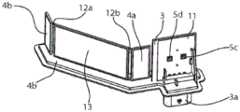
图2和3示出了第二实施例的倾斜视图,其中在这两个附图中省略了该壳体,并且在图3中省略了该壳体和照明装置的一部分。Figures 2 and 3 show oblique views of the second embodiment, wherein the housing is omitted in these two figures, and a part of the housing and the lighting device is omitted in Figure 3 .
具体实施方式Detailed ways
图1示出了电子组件1的第一实施例的侧面剖视图,其电子组件固定在机动车的车身构件14上。该电子组件在所示的实施例中包括带两个壳体部段 2a和2b的壳体2,这些壳体部段通过铰接区域6相互连接。FIG. 1 shows a sectional side view of a first exemplary embodiment of an electronic assembly 1 , the electronic assembly of which is fastened to a
在按本发明的第一实施例的电子组件的两个壳体部段2a、2b中设置有不同的另外的组件。在壳体部段2a中还设置有控制和评估装置3,并且具有与此控制和评估装置耦合的照明装置5a。照明装置5a在此实施例中包括灯具 5c。照明装置5a还包括透明的透孔5b,由灯具5c发射的光线能够穿透该透孔。通过该灯具5c在地面U上将目标范围Y标出来。照明装置5a配备有透镜结构5b,其设置在照明装置5a自身中。透镜结构5b根据灯具5c和地面U 之间的间距进行选择,因此总是使光线最佳地在地面上聚焦。照明装置还配备有自清洁的涂层9。Various additional components are provided in the two
在此壳体部段2a还设置有第一电容式传感器4a,它对探测范围X进行监控。第一电容式传感器和照明装置这样相互协调地设置,使得借助照明装置 5a投射在地面上的目标范围Y至少局部地与第一电容式传感器的探测范围X 重合。投入到地面上的目标范围因此有效地让用户知道,能够在机动车下方的哪个区域启动操纵。The
按本发明,此照明装置这样构成,使得由它能够由控制和评估电路操控,以便发射不同颜色的光线。为此,照明装置例如包括两个光源,其发射不同波长或波长范围的光线,或者分别配备相应的过滤器。为了使目标范围被用户清楚地看到,灯具5c由控制和评估电路操控,使得在不同的颜色之间进行重复快速地转换,例如以30Hz的频率。在地面不平时,目标范围的这种“闪耀”能够比仅用白光标出的目标范围明显更清楚地被用户感受到。According to the invention, the lighting device is designed such that it can be actuated by the control and evaluation circuit in order to emit light of different colors. For this purpose, the lighting device comprises, for example, two light sources, which emit light of different wavelengths or wavelength ranges, or are each equipped with corresponding filters. In order for the target range to be clearly seen by the user, the
在所示的实施例中,照明装置仅包括灯具5c,其能够被相应地操纵,即能够发射出不同颜色的光线。为此,灯具包括例如两个光源,它们发射出不同颜色的光线。In the embodiment shown, the lighting device comprises only
在所示的实施例中,电子组件还包括第一传感器10a,其与控制和评估装置3耦合并且设置在车身构件14的凹槽中。借助该传感器能够获在地面U的特性,并且根据此特性能够通过控制和评估装置对照明装置进行最佳的操控,因此总是根据获知的地面为用户提供最佳的标记。In the exemplary embodiment shown, the electronic assembly also includes a
电子组件还包括第二传感器10b,借助它来获知照明装置5a下方的区域的亮度。然后根据获知的亮度,能够借助控制和评估装置来调节目标范围的最佳标记(如果能够发射出多于两个不同的颜色,则调节这些颜色之间的变换频率或颜色本身)。The electronic assembly also includes a
对于第一壳体部段2a来说,还在车身构件上固定着喷嘴结构11,借助它能够对照明装置的使光线从照明装置中射出的区域进行清洁。In the case of the
在所示的实施例中,该电子组件还包括第二壳体部段2b,第二电容式传感器4b设置在此壳体部段中,借助该传感器能够对第二(未示出的)探测范围进行监控。对于这两个传感器来说,应注意,在其它实施例中也可以将它们省略,它们自身不是按本发明的组件的重要组成部分。In the embodiment shown, the electronic assembly also comprises a
图2和3示出了电子组件的第二实施例的侧视图,其中为了使视觉清晰在图2中省略了该壳体,并且在图3中省略了该壳体和照明装置的一部分。Figures 2 and 3 show side views of a second embodiment of an electronic assembly, wherein the housing is omitted in Figure 2 for clarity of vision, and a portion of the housing and lighting device are omitted in Figure 3 .
在第二实施例中,两个电容式传感器4a和4b通过间隔垫片13相互隔开,其中该间隔垫片通过耦合元件12a、12b与第一和第二电容式传感器耦合,并因此在这两个传感器和控制和评估电路之间建立连接。In the second embodiment, the two
按此实施例的照明装置5a与第一实施例的区别在于,该照明装置包括两个灯具5c、5d,其中这两个灯具发射出具有不同波长范围/其它颜色的光线。如果该照明装置“只”发射出两种颜色,则它们优选是红色和绿色,因为在两个颜色之间的变化对于操纵者来说是尤其容易识别的。The
在备选的实施例中,照明装置能够具有多个灯具,因此能够使用复杂的颜色变化来突出目标范围。这种“调光器”能够通过控制和评估装置与车辆内部的控制耦合个性化地与操纵者相匹配。In alternative embodiments, the lighting device can have multiple light fixtures, so complex color variations can be used to highlight the target range. This "dimmer" can be individually adapted to the operator by means of the control and evaluation device and the control coupling inside the vehicle.
Claims (8)
Applications Claiming Priority (3)
| Application Number | Priority Date | Filing Date | Title |
|---|---|---|---|
| DE102014106939.0 | 2014-05-16 | ||
| DE102014106939.0ADE102014106939A1 (en) | 2014-05-16 | 2014-05-16 | Electronic assembly for illuminating a target area marking a detection area of a sensor |
| PCT/EP2015/056761WO2015172934A1 (en) | 2014-05-16 | 2015-03-27 | Electronic assembly for illuminating a target area marking a detection area of a sensor |
Publications (2)
| Publication Number | Publication Date |
|---|---|
| CN106458086A CN106458086A (en) | 2017-02-22 |
| CN106458086Btrue CN106458086B (en) | 2020-03-13 |
Family
ID=52781079
Family Applications (1)
| Application Number | Title | Priority Date | Filing Date |
|---|---|---|---|
| CN201580022899.XAActiveCN106458086B (en) | 2014-05-16 | 2015-03-27 | Electronic assembly for illuminating a target range marking the detection range of a sensor |
Country Status (6)
| Country | Link |
|---|---|
| US (1) | US10507762B2 (en) |
| EP (1) | EP3142898B1 (en) |
| JP (1) | JP6681842B2 (en) |
| CN (1) | CN106458086B (en) |
| DE (1) | DE102014106939A1 (en) |
| WO (1) | WO2015172934A1 (en) |
Families Citing this family (5)
| Publication number | Priority date | Publication date | Assignee | Title |
|---|---|---|---|---|
| JP6483759B2 (en)* | 2017-06-29 | 2019-03-13 | 本田技研工業株式会社 | Working machine |
| JP6606133B2 (en)* | 2017-07-31 | 2019-11-13 | 本田技研工業株式会社 | snowblower |
| DE102021115259A1 (en) | 2021-06-14 | 2022-12-15 | Huf Hülsbeck & Fürst Gmbh & Co. Kg | Method for evaluating a sensor device |
| DE102021115258A1 (en) | 2021-06-14 | 2022-12-15 | Huf Hülsbeck & Fürst Gmbh & Co. Kg | Method for evaluating a sensor device |
| EP4470834A1 (en)* | 2023-06-01 | 2024-12-04 | Valeo Vision | Automotive luminous device including a sensor to open a vehicle element |
Citations (4)
| Publication number | Priority date | Publication date | Assignee | Title |
|---|---|---|---|---|
| US5008595A (en)* | 1985-12-18 | 1991-04-16 | Laser Link, Inc. | Ornamental light display apparatus |
| JP2007245939A (en)* | 2006-03-16 | 2007-09-27 | Asti Corp | Courtesy lamp |
| CN101342892A (en)* | 2007-07-10 | 2009-01-14 | 欧姆龙株式会社 | Surroundings detecting device, method and program |
| CN102267419A (en)* | 2010-04-28 | 2011-12-07 | 株式会社电装 | Cover of vehicle optical sensor and vehicle optical sensor device |
Family Cites Families (22)
| Publication number | Priority date | Publication date | Assignee | Title |
|---|---|---|---|---|
| US3913840A (en)* | 1974-06-26 | 1975-10-21 | Lawrence Peska Ass Inc | Headlight cleaner for vehicles |
| DE4008280A1 (en)* | 1990-03-15 | 1991-09-19 | Tzn Forschung & Entwicklung | Indicating ice etc. on road surface - using IR detector and halogen lamp source with beam modulator and narrow bandpass filter |
| US5243185A (en)* | 1992-07-31 | 1993-09-07 | Loral Aerospace Corp. | Apparatus and method for ice detection |
| WO1995001549A1 (en)* | 1993-06-29 | 1995-01-12 | Omron Corporation | Road-surface examining device and device using it |
| JPH11165585A (en)* | 1997-12-05 | 1999-06-22 | Toyoda Gosei Co Ltd | Out-vehicle lighting system |
| JPH11321440A (en)* | 1998-05-18 | 1999-11-24 | Koito Mfg Co Ltd | Lighting fixture device for vehicle |
| JP4028135B2 (en)* | 1999-05-27 | 2007-12-26 | 本田技研工業株式会社 | Object detection device |
| US6854870B2 (en)* | 2001-06-30 | 2005-02-15 | Donnelly Corporation | Vehicle handle assembly |
| AU2004219513B2 (en)* | 2003-03-14 | 2009-08-27 | Liwas Aps | A device for detection of road surface condition |
| JP2006090033A (en)* | 2004-09-24 | 2006-04-06 | Fujikura Ltd | Automatic door opening device |
| US20060087231A1 (en)* | 2004-10-27 | 2006-04-27 | Eastman Kodak Company | Self-cleaning area illumination system |
| DE102005023617A1 (en)* | 2005-05-21 | 2006-11-23 | Aspre Ag | Method for mixing colors in a display |
| US8333492B2 (en)* | 2007-05-03 | 2012-12-18 | Donnelly Corporation | Illumination module for a vehicle |
| JP4719284B2 (en)* | 2008-10-10 | 2011-07-06 | トヨタ自動車株式会社 | Surface inspection device |
| JP2010257832A (en)* | 2009-04-27 | 2010-11-11 | Koito Mfg Co Ltd | Lighting fixture washing structure |
| JP5237894B2 (en)* | 2009-07-07 | 2013-07-17 | 本田技研工業株式会社 | Vehicle lighting device |
| TWM398600U (en)* | 2009-11-30 | 2011-02-21 | Top Energy Saving System Corp | Lighting apparatus |
| JP5382050B2 (en) | 2011-04-06 | 2014-01-08 | アイシン精機株式会社 | Opening and closing body actuator for vehicle |
| US8801245B2 (en) | 2011-11-14 | 2014-08-12 | Magna Mirrors Of America, Inc. | Illumination module for vehicle |
| DE102012216088A1 (en)* | 2012-09-11 | 2014-03-13 | Robert Bosch Gmbh | Method and evaluation and control unit for adjusting a headlight beam boundary of a headlight cone |
| DE102012109031A1 (en)* | 2012-09-25 | 2014-03-27 | Huf Hülsbeck & Fürst Gmbh & Co. Kg | Electronic sensor unit for detecting the contactless actuation of a door or flap on a motor vehicle |
| CN110650505B (en) | 2013-03-21 | 2022-04-08 | 北京三星通信技术研究有限公司 | Method for supporting switching |
- 2014
- 2014-05-16DEDE102014106939.0Apatent/DE102014106939A1/ennot_activeWithdrawn
- 2015
- 2015-03-27CNCN201580022899.XApatent/CN106458086B/enactiveActive
- 2015-03-27WOPCT/EP2015/056761patent/WO2015172934A1/enactiveApplication Filing
- 2015-03-27EPEP15713460.2Apatent/EP3142898B1/enactiveActive
- 2015-03-27JPJP2016567078Apatent/JP6681842B2/enactiveActive
- 2015-03-27USUS15/311,483patent/US10507762B2/enactiveActive
Patent Citations (4)
| Publication number | Priority date | Publication date | Assignee | Title |
|---|---|---|---|---|
| US5008595A (en)* | 1985-12-18 | 1991-04-16 | Laser Link, Inc. | Ornamental light display apparatus |
| JP2007245939A (en)* | 2006-03-16 | 2007-09-27 | Asti Corp | Courtesy lamp |
| CN101342892A (en)* | 2007-07-10 | 2009-01-14 | 欧姆龙株式会社 | Surroundings detecting device, method and program |
| CN102267419A (en)* | 2010-04-28 | 2011-12-07 | 株式会社电装 | Cover of vehicle optical sensor and vehicle optical sensor device |
Also Published As
| Publication number | Publication date |
|---|---|
| EP3142898A1 (en) | 2017-03-22 |
| JP6681842B2 (en) | 2020-04-15 |
| DE102014106939A1 (en) | 2015-11-19 |
| US20170088042A1 (en) | 2017-03-30 |
| JP2017515730A (en) | 2017-06-15 |
| CN106458086A (en) | 2017-02-22 |
| EP3142898B1 (en) | 2020-01-08 |
| WO2015172934A1 (en) | 2015-11-19 |
| US10507762B2 (en) | 2019-12-17 |
Similar Documents
| Publication | Publication Date | Title |
|---|---|---|
| CN106458086B (en) | Electronic assembly for illuminating a target range marking the detection range of a sensor | |
| US8003923B2 (en) | Household appliance with display that is raised from a surface | |
| JP6612781B2 (en) | Assembly module | |
| JP7019653B2 (en) | Methods and devices for controlling the lighting unit based on the measured force and / or the movement of the associated luminaire. | |
| US7292281B2 (en) | Monitoring camera with a far infrared capability | |
| JP6173471B2 (en) | Method and apparatus for illuminating an object | |
| US20170106836A1 (en) | Vehicle function control system using sensing and icon display module | |
| CN104620505B (en) | Electronic sensor unit for detecting contactless operation of doors or door covers on motor vehicles | |
| RU2674741C2 (en) | Vehicle reading lamp with low intensity light setting and method of controlling lamp | |
| KR101305808B1 (en) | Organic EL light device for automobile | |
| ATE496258T1 (en) | OPERATIONAL LIGHT WITH DISTANCE-DEPENDENT BRIGHTNESS CONTROL | |
| CN106715196B (en) | vehicle rear lights | |
| DE112013003514T5 (en) | Lighting control device, lighting source and lighting system | |
| ATE531014T1 (en) | WARNING LIGHT DEVICE WITH AT LEAST TWO WARNING LIGHTS | |
| WO2019014112A1 (en) | Hazard detector with optical status indicator | |
| JP2007514129A (en) | Display device having combined light guide | |
| CN119738929A (en) | Optical module, intelligent mobile device and mode switching method | |
| US20120104971A1 (en) | Operating Device for Driving a Multicolored Light Source and Illumination Device | |
| JPWO2013187004A1 (en) | Hand dryer | |
| KR101688406B1 (en) | Pattern luminescence led signal lamp | |
| RU2016131179A (en) | LUMINESCENT COMPONENT OF ANALOG ANALYSIS | |
| JP2005222824A (en) | Optical sensor switch | |
| JP2018511145A5 (en) | ||
| CN104952274A (en) | Parking lot warning lamp | |
| KR101582382B1 (en) | Illumination device and frame having illumination |
Legal Events
| Date | Code | Title | Description |
|---|---|---|---|
| C06 | Publication | ||
| PB01 | Publication | ||
| SE01 | Entry into force of request for substantive examination | ||
| SE01 | Entry into force of request for substantive examination | ||
| GR01 | Patent grant |