CN106456848B - Debridement dressings for use with negative pressure and fluid instillation - Google Patents
Debridement dressings for use with negative pressure and fluid instillationDownload PDFInfo
- Publication number
- CN106456848B CN106456848BCN201580026901.0ACN201580026901ACN106456848BCN 106456848 BCN106456848 BCN 106456848BCN 201580026901 ACN201580026901 ACN 201580026901ACN 106456848 BCN106456848 BCN 106456848B
- Authority
- CN
- China
- Prior art keywords
- debridement tool
- tissue
- debridement
- holes
- negative pressure
- Prior art date
- Legal status (The legal status is an assumption and is not a legal conclusion. Google has not performed a legal analysis and makes no representation as to the accuracy of the status listed.)
- Active
Links
Images


Classifications
- A—HUMAN NECESSITIES
- A61—MEDICAL OR VETERINARY SCIENCE; HYGIENE
- A61B—DIAGNOSIS; SURGERY; IDENTIFICATION
- A61B17/00—Surgical instruments, devices or methods
- A61B17/32—Surgical cutting instruments
- A—HUMAN NECESSITIES
- A61—MEDICAL OR VETERINARY SCIENCE; HYGIENE
- A61B—DIAGNOSIS; SURGERY; IDENTIFICATION
- A61B17/00—Surgical instruments, devices or methods
- A61B17/32—Surgical cutting instruments
- A61B17/3205—Excision instruments
- A—HUMAN NECESSITIES
- A61—MEDICAL OR VETERINARY SCIENCE; HYGIENE
- A61F—FILTERS IMPLANTABLE INTO BLOOD VESSELS; PROSTHESES; DEVICES PROVIDING PATENCY TO, OR PREVENTING COLLAPSING OF, TUBULAR STRUCTURES OF THE BODY, e.g. STENTS; ORTHOPAEDIC, NURSING OR CONTRACEPTIVE DEVICES; FOMENTATION; TREATMENT OR PROTECTION OF EYES OR EARS; BANDAGES, DRESSINGS OR ABSORBENT PADS; FIRST-AID KITS
- A61F13/00—Bandages or dressings; Absorbent pads
- A61F13/01—Non-adhesive bandages or dressings
- A61F13/01008—Non-adhesive bandages or dressings characterised by the material
- A61F13/01017—Non-adhesive bandages or dressings characterised by the material synthetic, e.g. polymer based
- A—HUMAN NECESSITIES
- A61—MEDICAL OR VETERINARY SCIENCE; HYGIENE
- A61F—FILTERS IMPLANTABLE INTO BLOOD VESSELS; PROSTHESES; DEVICES PROVIDING PATENCY TO, OR PREVENTING COLLAPSING OF, TUBULAR STRUCTURES OF THE BODY, e.g. STENTS; ORTHOPAEDIC, NURSING OR CONTRACEPTIVE DEVICES; FOMENTATION; TREATMENT OR PROTECTION OF EYES OR EARS; BANDAGES, DRESSINGS OR ABSORBENT PADS; FIRST-AID KITS
- A61F13/00—Bandages or dressings; Absorbent pads
- A61F13/05—Bandages or dressings; Absorbent pads specially adapted for use with sub-pressure or over-pressure therapy, wound drainage or wound irrigation, e.g. for use with negative-pressure wound therapy [NPWT]
- A—HUMAN NECESSITIES
- A61—MEDICAL OR VETERINARY SCIENCE; HYGIENE
- A61L—METHODS OR APPARATUS FOR STERILISING MATERIALS OR OBJECTS IN GENERAL; DISINFECTION, STERILISATION OR DEODORISATION OF AIR; CHEMICAL ASPECTS OF BANDAGES, DRESSINGS, ABSORBENT PADS OR SURGICAL ARTICLES; MATERIALS FOR BANDAGES, DRESSINGS, ABSORBENT PADS OR SURGICAL ARTICLES
- A61L31/00—Materials for other surgical articles, e.g. stents, stent-grafts, shunts, surgical drapes, guide wires, materials for adhesion prevention, occluding devices, surgical gloves, tissue fixation devices
- A61L31/04—Macromolecular materials
- A61L31/06—Macromolecular materials obtained otherwise than by reactions only involving carbon-to-carbon unsaturated bonds
- A—HUMAN NECESSITIES
- A61—MEDICAL OR VETERINARY SCIENCE; HYGIENE
- A61L—METHODS OR APPARATUS FOR STERILISING MATERIALS OR OBJECTS IN GENERAL; DISINFECTION, STERILISATION OR DEODORISATION OF AIR; CHEMICAL ASPECTS OF BANDAGES, DRESSINGS, ABSORBENT PADS OR SURGICAL ARTICLES; MATERIALS FOR BANDAGES, DRESSINGS, ABSORBENT PADS OR SURGICAL ARTICLES
- A61L31/00—Materials for other surgical articles, e.g. stents, stent-grafts, shunts, surgical drapes, guide wires, materials for adhesion prevention, occluding devices, surgical gloves, tissue fixation devices
- A61L31/14—Materials characterised by their function or physical properties, e.g. injectable or lubricating compositions, shape-memory materials, surface modified materials
- A61L31/146—Porous materials, e.g. foams or sponges
- A—HUMAN NECESSITIES
- A61—MEDICAL OR VETERINARY SCIENCE; HYGIENE
- A61M—DEVICES FOR INTRODUCING MEDIA INTO, OR ONTO, THE BODY; DEVICES FOR TRANSDUCING BODY MEDIA OR FOR TAKING MEDIA FROM THE BODY; DEVICES FOR PRODUCING OR ENDING SLEEP OR STUPOR
- A61M1/00—Suction or pumping devices for medical purposes; Devices for carrying-off, for treatment of, or for carrying-over, body-liquids; Drainage systems
- A61M1/90—Negative pressure wound therapy devices, i.e. devices for applying suction to a wound to promote healing, e.g. including a vacuum dressing
- A61M1/91—Suction aspects of the dressing
- A61M1/915—Constructional details of the pressure distribution manifold
- A—HUMAN NECESSITIES
- A61—MEDICAL OR VETERINARY SCIENCE; HYGIENE
- A61B—DIAGNOSIS; SURGERY; IDENTIFICATION
- A61B17/00—Surgical instruments, devices or methods
- A61B2017/00743—Type of operation; Specification of treatment sites
- A61B2017/00747—Dermatology
- A61B2017/00761—Removing layer of skin tissue, e.g. wrinkles, scars or cancerous tissue
- A—HUMAN NECESSITIES
- A61—MEDICAL OR VETERINARY SCIENCE; HYGIENE
- A61B—DIAGNOSIS; SURGERY; IDENTIFICATION
- A61B17/00—Surgical instruments, devices or methods
- A61B17/32—Surgical cutting instruments
- A61B2017/320004—Surgical cutting instruments abrasive
- A—HUMAN NECESSITIES
- A61—MEDICAL OR VETERINARY SCIENCE; HYGIENE
- A61B—DIAGNOSIS; SURGERY; IDENTIFICATION
- A61B17/00—Surgical instruments, devices or methods
- A61B17/32—Surgical cutting instruments
- A61B2017/320004—Surgical cutting instruments abrasive
- A61B2017/320008—Scrapers
- A—HUMAN NECESSITIES
- A61—MEDICAL OR VETERINARY SCIENCE; HYGIENE
- A61B—DIAGNOSIS; SURGERY; IDENTIFICATION
- A61B17/00—Surgical instruments, devices or methods
- A61B17/32—Surgical cutting instruments
- A61B2017/32006—Surgical cutting instruments with a cutting strip, band or chain, e.g. like a chainsaw
- A—HUMAN NECESSITIES
- A61—MEDICAL OR VETERINARY SCIENCE; HYGIENE
- A61F—FILTERS IMPLANTABLE INTO BLOOD VESSELS; PROSTHESES; DEVICES PROVIDING PATENCY TO, OR PREVENTING COLLAPSING OF, TUBULAR STRUCTURES OF THE BODY, e.g. STENTS; ORTHOPAEDIC, NURSING OR CONTRACEPTIVE DEVICES; FOMENTATION; TREATMENT OR PROTECTION OF EYES OR EARS; BANDAGES, DRESSINGS OR ABSORBENT PADS; FIRST-AID KITS
- A61F13/00—Bandages or dressings; Absorbent pads
- A61F2013/00089—Wound bandages
- A61F2013/0017—Wound bandages possibility of applying fluid
- A61F2013/00174—Wound bandages possibility of applying fluid possibility of applying pressure
- A—HUMAN NECESSITIES
- A61—MEDICAL OR VETERINARY SCIENCE; HYGIENE
- A61F—FILTERS IMPLANTABLE INTO BLOOD VESSELS; PROSTHESES; DEVICES PROVIDING PATENCY TO, OR PREVENTING COLLAPSING OF, TUBULAR STRUCTURES OF THE BODY, e.g. STENTS; ORTHOPAEDIC, NURSING OR CONTRACEPTIVE DEVICES; FOMENTATION; TREATMENT OR PROTECTION OF EYES OR EARS; BANDAGES, DRESSINGS OR ABSORBENT PADS; FIRST-AID KITS
- A61F13/00—Bandages or dressings; Absorbent pads
- A61F2013/00089—Wound bandages
- A61F2013/0028—Wound bandages applying of mechanical pressure; passive massage
- A—HUMAN NECESSITIES
- A61—MEDICAL OR VETERINARY SCIENCE; HYGIENE
- A61K—PREPARATIONS FOR MEDICAL, DENTAL OR TOILETRY PURPOSES
- A61K45/00—Medicinal preparations containing active ingredients not provided for in groups A61K31/00 - A61K41/00
- A61K45/06—Mixtures of active ingredients without chemical characterisation, e.g. antiphlogistics and cardiaca
- A—HUMAN NECESSITIES
- A61—MEDICAL OR VETERINARY SCIENCE; HYGIENE
- A61L—METHODS OR APPARATUS FOR STERILISING MATERIALS OR OBJECTS IN GENERAL; DISINFECTION, STERILISATION OR DEODORISATION OF AIR; CHEMICAL ASPECTS OF BANDAGES, DRESSINGS, ABSORBENT PADS OR SURGICAL ARTICLES; MATERIALS FOR BANDAGES, DRESSINGS, ABSORBENT PADS OR SURGICAL ARTICLES
- A61L2400/00—Materials characterised by their function or physical properties
- A—HUMAN NECESSITIES
- A61—MEDICAL OR VETERINARY SCIENCE; HYGIENE
- A61M—DEVICES FOR INTRODUCING MEDIA INTO, OR ONTO, THE BODY; DEVICES FOR TRANSDUCING BODY MEDIA OR FOR TAKING MEDIA FROM THE BODY; DEVICES FOR PRODUCING OR ENDING SLEEP OR STUPOR
- A61M1/00—Suction or pumping devices for medical purposes; Devices for carrying-off, for treatment of, or for carrying-over, body-liquids; Drainage systems
- A61M1/71—Suction drainage systems
- A61M1/74—Suction control
- A61M1/75—Intermittent or pulsating suction
- A—HUMAN NECESSITIES
- A61—MEDICAL OR VETERINARY SCIENCE; HYGIENE
- A61M—DEVICES FOR INTRODUCING MEDIA INTO, OR ONTO, THE BODY; DEVICES FOR TRANSDUCING BODY MEDIA OR FOR TAKING MEDIA FROM THE BODY; DEVICES FOR PRODUCING OR ENDING SLEEP OR STUPOR
- A61M1/00—Suction or pumping devices for medical purposes; Devices for carrying-off, for treatment of, or for carrying-over, body-liquids; Drainage systems
- A61M1/90—Negative pressure wound therapy devices, i.e. devices for applying suction to a wound to promote healing, e.g. including a vacuum dressing
- A61M1/91—Suction aspects of the dressing
- A61M1/912—Connectors between dressing and drainage tube
- A—HUMAN NECESSITIES
- A61—MEDICAL OR VETERINARY SCIENCE; HYGIENE
- A61M—DEVICES FOR INTRODUCING MEDIA INTO, OR ONTO, THE BODY; DEVICES FOR TRANSDUCING BODY MEDIA OR FOR TAKING MEDIA FROM THE BODY; DEVICES FOR PRODUCING OR ENDING SLEEP OR STUPOR
- A61M1/00—Suction or pumping devices for medical purposes; Devices for carrying-off, for treatment of, or for carrying-over, body-liquids; Drainage systems
- A61M1/90—Negative pressure wound therapy devices, i.e. devices for applying suction to a wound to promote healing, e.g. including a vacuum dressing
- A61M1/92—Negative pressure wound therapy devices, i.e. devices for applying suction to a wound to promote healing, e.g. including a vacuum dressing with liquid supply means
- A—HUMAN NECESSITIES
- A61—MEDICAL OR VETERINARY SCIENCE; HYGIENE
- A61M—DEVICES FOR INTRODUCING MEDIA INTO, OR ONTO, THE BODY; DEVICES FOR TRANSDUCING BODY MEDIA OR FOR TAKING MEDIA FROM THE BODY; DEVICES FOR PRODUCING OR ENDING SLEEP OR STUPOR
- A61M1/00—Suction or pumping devices for medical purposes; Devices for carrying-off, for treatment of, or for carrying-over, body-liquids; Drainage systems
- A61M1/90—Negative pressure wound therapy devices, i.e. devices for applying suction to a wound to promote healing, e.g. including a vacuum dressing
- A61M1/94—Negative pressure wound therapy devices, i.e. devices for applying suction to a wound to promote healing, e.g. including a vacuum dressing with gas supply means
Landscapes
- Health & Medical Sciences (AREA)
- Life Sciences & Earth Sciences (AREA)
- Heart & Thoracic Surgery (AREA)
- General Health & Medical Sciences (AREA)
- Animal Behavior & Ethology (AREA)
- Public Health (AREA)
- Veterinary Medicine (AREA)
- Biomedical Technology (AREA)
- Engineering & Computer Science (AREA)
- Surgery (AREA)
- Vascular Medicine (AREA)
- Molecular Biology (AREA)
- Nuclear Medicine, Radiotherapy & Molecular Imaging (AREA)
- Medical Informatics (AREA)
- Chemical & Material Sciences (AREA)
- Anesthesiology (AREA)
- Hematology (AREA)
- Epidemiology (AREA)
- Organic Chemistry (AREA)
- Chemical Kinetics & Catalysis (AREA)
- Dispersion Chemistry (AREA)
- Media Introduction/Drainage Providing Device (AREA)
- Virology (AREA)
- AIDS & HIV (AREA)
- Tropical Medicine & Parasitology (AREA)
- Communicable Diseases (AREA)
- Oncology (AREA)
- General Chemical & Material Sciences (AREA)
- Medicinal Chemistry (AREA)
- Pharmacology & Pharmacy (AREA)
- Surgical Instruments (AREA)
Abstract
Description
Translated fromChinese本发明根据35USC§119(e)要求2014年5月9日提交的洛克(Locke)等人的题为“与负压和流体滴注一起使用的清创敷件(Debriding Dressing for use with NegativePressure and Fluid Instillation)”的美国临时专利申请序列号61/991,134的权益,该申请出于所有目的通过引用结合在此。This invention is required under 35 USC §119(e) by Locke et al., entitled "Debriding Dressing for use with Negative Pressure and Fluid Instillation," filed on May 9, 2014 Fluid Instillation)" of U.S. Provisional Patent Application Serial No. 61/991,134, which is hereby incorporated by reference for all purposes.
技术领域technical field
在所附权利要求书中阐述的本发明总体上涉及组织治疗系统,并且更具体地但是非限制地涉及一种用于对组织部位进行清创的敷件。The present invention as set forth in the appended claims relates generally to tissue treatment systems and more particularly, but not by way of limitation, to a dressing for debridement of a tissue site.
背景background
临床研究和实践已表明,降低在一个组织部位附近的压力可以增进并加速在该组织部位处的新组织的生长。此现象的应用有很多,但已证明其尤其有利于用于治疗伤口。不论伤口病因是外伤、手术、或其他原因,对伤口的适当护理对结果很重要。利用减压治疗伤口或其他组织通常可称为“负压治疗”,但是也以其他名称为人所知,例如包括“负压伤口治疗”、“减压治疗”、“真空治疗”、以及“封闭式负压引流”。负压治疗可以提供许多益处,包括上皮和皮下组织的迁移、改善血流、以及在伤口部位处的组织的微变形。这些益处可以共同增加肉芽组织的发育并且减少愈合时间。Clinical research and practice have shown that reducing pressure near a tissue site can enhance and accelerate the growth of new tissue at that tissue site. There are many applications of this phenomenon, but it has proven to be particularly beneficial for the treatment of wounds. Whether the cause of the wound is trauma, surgery, or other causes, proper wound care is important to the outcome. The use of reduced pressure to treat wounds or other tissues may often be referred to as "negative pressure therapy," but is also known by other names including, for example, "negative pressure wound therapy," "reduced pressure therapy," "vacuum therapy," and "occlusion." negative pressure drainage". Negative pressure therapy can provide many benefits, including migration of epithelial and subcutaneous tissue, improved blood flow, and micro-deformation of tissue at the wound site. Together, these benefits can increase granulation tissue development and reduce healing time.
虽然负压治疗的临床益处已众所周知,但负压治疗的成本和复杂性可能是其应用上的限制因素,并且负压系统、部件和过程的开发和操作一直是制造商、医疗保健提供者和患者所面临的重大挑战。While the clinical benefits of negative pressure therapy are well known, the cost and complexity of negative pressure therapy can be a limiting factor in its application, and the development and operation of negative pressure systems, components, and processes has been a constant challenge for manufacturers, healthcare providers, and significant challenges faced by patients.
简要概述Brief overview
在所附权利要求书中提出了用于在负压治疗环境中对组织进行清创的新的且有用的系统、装置和方法。还提供了多个说明性实施例以使得本领域技术人员能够制造和使用所要求保护的主题。例如,在此描述了一种系统,该系统包括适配成递送负压至组织部位的一个歧管。该系统还可以包括适配成在该歧管和该组织部位上形成一个密封空间以用于接收来自负压源的负压的一个覆盖件。该系统可以进一步包括定位在该歧管与该组织部位之间的一个清创工具。该清创工具可以具有一个面向组织表面和一个相反表面以及在两个表面之间延伸的多个孔。这些孔可以通过多个壁彼此分开,这些壁可以具有在该面向组织表面与该相反表面之间延伸的横向表面。这些横向表面可以与该面向组织表面形成切割边缘。这些孔可以具有一个穿孔形状系数,该穿孔形状系数允许这些孔响应于负压到该密封空间的施加和去除而从一个松弛位置塌陷到一个收缩位置。这些切割边缘可以响应于该清创工具在该松弛位置与该收缩位置之间的移动而对组织部位进行清创。New and useful systems, devices and methods for debridement of tissue in a negative pressure therapy environment are set forth in the appended claims. Various illustrative embodiments are also provided to enable any person skilled in the art to make and use the claimed subject matter. For example, a system is described herein that includes a manifold adapted to deliver negative pressure to a tissue site. The system may also include a cover adapted to form a sealed space over the manifold and the tissue site for receiving negative pressure from a negative pressure source. The system may further include a debridement tool positioned between the manifold and the tissue site. The debridement tool may have a tissue facing surface and an opposing surface and a plurality of holes extending between the two surfaces. The apertures may be separated from each other by walls, which may have lateral surfaces extending between the tissue facing surface and the opposing surface. The lateral surfaces may form cutting edges with the tissue facing surface. The holes may have a perforation form factor that allows the holes to collapse from a relaxed position to a collapsed position in response to the application and removal of negative pressure to the sealed space. The cutting edges can debride the tissue site in response to movement of the debridement tool between the relaxed position and the retracted position.
可替代地,另一个示例性实施例包括一种对组织部位进行清创的装置。该装置可以包括具有一个面向组织表面和一个相反表面、包括在两个表面之间延伸的多个孔的一个清创工具。这些孔可以通过多个壁彼此分开,并且这些壁可以具有在该面向组织表面与该相反表面之间延伸以与该面向组织表面形成切割边缘的横向表面。这些孔可以具有一个穿孔形状系数,该穿孔形状系数允许这些孔响应于负压的施加和去除而从一个松弛位置塌陷到一个收缩位置。这些切割边缘可以响应于该清创工具在该松弛位置与该收缩位置之间的移动而对组织部位进行清创。Alternatively, another exemplary embodiment includes a device for debriding a tissue site. The device can include a debridement tool having a tissue-facing surface and an opposing surface, including holes extending between the two surfaces. The holes may be separated from each other by walls, and the walls may have lateral surfaces extending between the tissue-facing surface and the opposing surface to form a cutting edge with the tissue-facing surface. The holes may have a perforation shape factor that allows the holes to collapse from a relaxed position to a collapsed position in response to the application and removal of negative pressure. The cutting edges can debride the tissue site in response to movement of the debridement tool between the relaxed position and the retracted position.
在此还描述了一种方法,其中一些示例性实施例包括一种用于对组织部位进行清创的方法。在一些实施例中,一个清创工具可以被定位来使得该清创工具的面向组织表面邻近该组织部位并覆盖该组织部位。该清创工具可以具有在由多个壁彼此分开的该面向组织表面与一个相反表面之间延伸的多个孔。这些壁可以具有在该面向组织表面与该相反表面之间延伸以与该面向组织表面形成切割边缘的横向表面。这些孔可以具有一个穿孔形状系数,该穿孔形状系数允许这些孔大体上垂直于该清创工具的对称线而从一个松弛位置塌陷到一个收缩位置。一个密封构件可以被定位在该清创工具上并且被密封至该组织部位周围的组织处以形成其中具有该清创工具的一个密封空间。一个负压源可以流体联接至该密封空间并且负压可以被施加至该密封空间以收缩该清创工具。负压可以从该密封空间排出,以使该清创工具膨胀。Also described herein is a method in which some exemplary embodiments include a method for debridement of a tissue site. In some embodiments, a debridement tool can be positioned such that the tissue-facing surface of the debridement tool is adjacent to and covers the tissue site. The debridement tool may have holes extending between the tissue facing surface and an opposing surface separated from each other by walls. The walls may have transverse surfaces extending between the tissue facing surface and the opposing surface to form a cutting edge with the tissue facing surface. The holes may have a perforation shape factor that allows the holes to collapse from a relaxed position to a retracted position generally perpendicular to the line of symmetry of the debridement tool. A sealing member can be positioned on the debridement tool and sealed to tissue surrounding the tissue site to form a sealed space with the debridement tool therein. A negative pressure source can be fluidly coupled to the sealed space and negative pressure can be applied to the sealed space to deflate the debridement tool. Negative pressure can be vented from the sealed space to inflate the debridement tool.
在此还描述了一种用于治疗组织部位的系统。该系统可以包括适配成递送负压至该组织部位并具有一个第一硬度系数的歧管。该系统还可以包括适配成在该歧管和该组织部位上形成一个密封空间以用于接收来自负压源的负压的一个覆盖件。在一些实施例中,该系统可以包括适配成定位在该歧管与该组织部位之间的一个组织界面。该组织界面可以具有大于该第一硬度系数的一个第二硬度系数和由多个壁彼此分开的多个孔。Also described herein is a system for treating a tissue site. The system can include a manifold adapted to deliver negative pressure to the tissue site and having a first stiffness coefficient. The system may also include a cover adapted to form a sealed space over the manifold and the tissue site for receiving negative pressure from a negative pressure source. In some embodiments, the system can include a tissue interface adapted to be positioned between the manifold and the tissue site. The tissue interface may have a second stiffness coefficient greater than the first stiffness coefficient and pores separated from each other by walls.
结合说明性实施例的以下详细描述参考以下附图,可以最佳地了解产生和使用所要求主题的目的、优点和优选方式。The objects, advantages, and preferred ways of making and using the claimed subject matter can be best understood by referring to the following drawings in conjunction with the following detailed description of illustrative embodiments.
附图简单说明Brief description of the attached drawings
图1是具有以正视图示出的一部分的横剖面图,它示出了可以与一种负压治疗系统的一些实施例相关的细节;1 is a cross-sectional view with a portion shown in front view showing details that may be associated with some embodiments of a negative pressure therapy system;
图1A是图1的负压治疗系统的一部分的详细视图;1A is a detailed view of a portion of the negative pressure therapy system of FIG. 1;
图2是示出可以与图1的负压治疗系统的一种清创工具在第一位置中的一些实施例相关的细节的平面图;2 is a plan view showing details that may be associated with some embodiments of a debridement tool of the negative pressure therapy system of FIG. 1 in a first position;
图3是示出可以与图2的清创工具的一个孔的一些实施例相关的细节的示意图;3 is a schematic diagram showing details that may be associated with some embodiments of one aperture of the debridement tool of FIG. 2;
图4是示出可以与图2的清创工具的这些孔的一些实施例相关的细节的平面图;4 is a plan view showing details that may be associated with some embodiments of the holes of the debridement tool of FIG. 2;
图5是示出可以与图2的清创工具在第二位置中的一些实施例相关的细节的平面图;5 is a plan view showing details that may be associated with some embodiments of the debridement tool of FIG. 2 in a second position;
图6是示出可以与图1的负压治疗系统的另一种清创工具的一些实施例相关的细节的平面图;6 is a plan view showing details that may be associated with some embodiments of another debridement tool of the negative pressure therapy system of FIG. 1;
图7是示出可以与图6的清创工具的一个孔的一些实施例相关的细节的示意图;7 is a schematic diagram showing details that may be associated with some embodiments of one aperture of the debridement tool of FIG. 6;
图8是示出可以与图6的清创工具的这些孔的一些实施例相关的细节的平面图;Figure 8 is a plan view showing details that may be associated with some embodiments of the holes of the debridement tool of Figure 6;
图9A是示出可以与图1的负压治疗系统的另一种清创工具的一些实施例相关的细节的平面图;9A is a plan view showing details that may be associated with some embodiments of another debridement tool of the negative pressure therapy system of FIG. 1;
图9B是示出可以与图9A的清创工具的这些孔的一些实施例相关的细节的平面图;9B is a plan view showing details that may be associated with some embodiments of the holes of the debridement tool of FIG. 9A;
图10是示出可以与图9A的清创工具的具有一个穿孔形状系数的一个孔的一些实施例相关的细节的示意图;10 is a schematic diagram illustrating details that may be associated with some embodiments of a hole having a perforation form factor of the debridement tool of FIG. 9A;
图11是示出可以与图9A的清创工具的具有另一个穿孔形状系数的一个孔的一些实施例相关的细节的示意图;11 is a schematic diagram showing details that may be associated with some embodiments of one aperture of the debridement tool of FIG. 9A having another perforation form factor;
图12是示出可以与图9A的清创工具的具有另一个穿孔形状系数的一个孔的一些实施例相关的细节的示意图;12 is a schematic diagram showing details that may be associated with some embodiments of one aperture of the debridement tool of FIG. 9A having another perforation form factor;
图13A是示出可以与图1的负压治疗系统的另一种清创工具的一些实施例相关的细节的平面图;13A is a plan view showing details that may be associated with some embodiments of another debridement tool of the negative pressure therapy system of FIG. 1;
图13B是示出可以与图13A的清创工具的这些孔的一些实施例相关的细节的平面图;Figure 13B is a plan view showing details that may be associated with some embodiments of the holes of the debridement tool of Figure 13A;
图14是示出可以与图13A的清创工具的一个孔的一些实施例相关的细节的示意图;并且14 is a schematic diagram showing details that may be associated with some embodiments of one aperture of the debridement tool of FIG. 13A; and
图15是示出可以与图1的负压治疗系统的另一种清创工具的一些实施例相关的细节的平面图。15 is a plan view showing details that may be associated with some embodiments of another debridement tool of the negative pressure therapy system of FIG. 1 .
示例性实施方式的说明Description of Exemplary Embodiments
示例性实施例的以下描述提供了使得本领域技术人员能够制造和使用所附权利要求书中阐述的主题的信息,但是可以省略本领域已经熟知的某些细节。因此,以下详细说明应被理解为是说明性的而非限制性的。The following description of exemplary embodiments provides information to enable one skilled in the art to make and use the subject matter set forth in the appended claims, but certain details that are already well known in the art may be omitted. Accordingly, the following detailed description is to be regarded in an illustrative rather than a restrictive sense.
在此还可参考不同元件之间的空间关系或参考这些附图中描绘的不同元件的空间定向来描述这些示例性实施例。一般而言,这样的关系或定向假定一个参考框架,该参考框架与待接受治疗的患者一致或者相对于该患者而言。然而,正如本领域的技术人员应当认识到的,这个参考框架仅仅是描述性的权宜措施,而不是严格规定。The exemplary embodiments may also be described herein with reference to the spatial relationship between the various elements or with reference to the spatial orientation of the various elements as depicted in the figures. In general, such a relationship or orientation assumes a frame of reference that is consistent with or relative to the patient to be treated. However, as those skilled in the art will appreciate, this frame of reference is merely a descriptive expedient rather than a strict rule.
图1是治疗系统100的一个示例性实施例具有以正视图示出的一部分的剖面图,所述治疗系统可以提供负压治疗、局部治疗溶液的滴注和根据本说明书的清创。治疗系统100可以包括一个敷件和一个负压源。例如,敷件102可以流体联接至负压源104,如图1所示的。图1A是图1的治疗系统100的一部分的详细视图。如图1和图1A所示的,敷件102例如包括覆盖件106和用于定位成与组织部位例如像组织部位103相邻或邻近的组织界面107。在一些实施例中,组织界面107可以是一个歧管,例如歧管108。在一些实施例中,组织界面107可以是一种组织去除工具,诸如具有适配成面向组织部位103的面向组织表面111和适配成面向例如歧管108的相反表面113的清创工具110。在其他实施例中,组织界面107可以是清创工具110和歧管108二者。治疗系统100还可以包括联接到敷件102和负压源104的渗出物容器,诸如容器112。在一些实施例中,容器112可以通过一个连接器114和一根管116流体联接至敷件102,并且容器112可以通过一根管118流体联接至负压源104。1 is a cross-sectional view with a portion shown in front view of an exemplary embodiment of a
在一些实施例中,治疗系统100还可以包括一个滴注溶液源。例如,流体源120可以通过一根管122和连接器124流体联接至敷件102,如图1的示例性实施例所示的。In some embodiments, the
一般而言,治疗系统100的多个部件可以直接或间接地联接。例如,负压源104可以直接联接到容器112并且通过容器112间接地联接到敷件102。多个部件可以彼此流体联接,以提供用于在这些部件之间传递流体(即,液体和/或气体)的一个路径。In general, various components of
在一些实施例中,例如,多个部件可以通过一根管诸如管116、管118和管122流体联接。如在此使用的一根“管”广泛地指管、管道、软管、导管或具有被适配成在两个末端之间传送流体的一个或多个管腔的其他结构。典型地,一根管是具有一定柔性的一种细长圆柱形结构,但是几何形状和刚性可以改变。在一些实施例中,多个部件可以另外地或可替代地凭借物理接近而联接,在整体上成为单一结构,或者由同一件材料形成。在一些情形下,联接还可以包括机械联接、热联接、电联接、或化学联接(诸如化学键)。In some embodiments, components may be fluidly coupled by a single tube such as
“连接器”诸如连接器114和连接器124可以用于将一根管流体联接至一个密封治疗环境。由一个负压源产生的负压可以通过一根管递送到一个连接器。在一个说明性实施例中,一个连接器可以是可获自德克萨斯州圣安东尼奥市(San Antonio,Texas)的KCI的

在操作中,组织界面107可以置于组织部位103之内、上方、之上、或以其他方式紧邻该组织部位。覆盖件106可以置于组织界面107上方并且被密封到该组织部位附近的组织上。例如,覆盖件106可以被密封到组织部位外围未损害的表皮,也称为外周组织(peritissue)。因此,敷件102可以提供一个紧邻组织部位的密封治疗环境128,该治疗环境基本上与外部环境隔离,并且负压源104可以降低密封治疗环境128中的压力。通过组织界面107施加在密封治疗环境128中的整个组织部位103上的负压可以引起组织部位103中的宏应变和微应变,并且从组织部位103移除渗出物和其他流体,这些渗出物和其他流体可以收集在容器112中并予以适当处理。In operation,
使用一个负压源来降低另一个部件或位置中(诸如在一个密封治疗环境内)的压力的流体力学可以是在数学上复杂的。然而,可适用于负压治疗和滴注的流体力学的基本原理通常是本领域技术人员所熟知的。The fluid mechanics of using a source of negative pressure to reduce pressure in another component or location, such as within a sealed treatment environment, can be mathematically complex. However, the basic principles of fluid mechanics applicable to negative pressure therapy and instillation are generally well known to those skilled in the art.
一般而言,流体沿着一个流体路径朝向更低压力的方向流动。因此,术语“下游”典型地是指在流体路径中更接近负压源或可替代地离正压源更远的一个位置。相反地,术语“上游”通常是指在流体路径中离负压源更远或更接近正压源的一个位置。类似地,在此参照系中的术语流体“入口”或“出口”便于描述某些特征,并且减压过程在此可以说明性地描述为例如“递送”、“分布”或“生成”减压。这种定向总体上被假定是为了描述在此的系统的不同特征和部件。In general, fluid flows in a direction of lower pressure along a fluid path. Thus, the term "downstream" typically refers to a location in the fluid path that is closer to the source of negative pressure or, alternatively, further from the source of positive pressure. Conversely, the term "upstream" generally refers to a location in the fluid path that is further or closer to the source of negative pressure. Similarly, the term fluid "inlet" or "outlet" in this frame of reference is convenient to describe certain features, and a reduced pressure process may be illustratively described herein as, for example, "delivering," "distributing," or "generating" reduced pressure . This orientation is generally assumed to describe the various features and components of the systems herein.
在这种情况下,术语“组织部位”诸如组织部位103广泛地是指位于组织上或组织内的伤口或缺损,该组织包括(但不限于)骨组织、脂肪组织、肌肉组织、神经组织、皮肤组织、血管组织、结缔组织、软骨、肌腱或韧带。伤口可以包括例如慢性、急性、外伤性、亚急性以及裂开的伤口、部分皮层烧伤、溃疡(诸如糖尿病性溃疡、压力性溃疡或静脉功能不全溃疡)、皮瓣、以及移植物。术语“组织部位”还可以是指不一定受伤的或缺损的组织区域,但是为在其中可能希望增加或促进另外的组织生长的替代区域。例如,负压可以用于某些组织区域中以使可以被收获并且移植到另一个组织位置的另外的组织生长。In this context, the term "tissue site" such as
“负压”通常是指小于局部环境压力的压力,该局部环境压力诸如由敷件102提供的在密封治疗环境外部的局部环境中的环境压力。在许多情况下,局部环境压力还可以是组织部位所处位置的大气压。可替代地,该压力可以小于与组织部位处的组织相关联的流体静压。除非另外说明,否则在此所陈述的压力的值是表压。类似地,提及负压的增加典型地是指绝对压力的降低,而负压的降低典型地是指绝对压力的增加。"Negative pressure" generally refers to a pressure that is less than the local ambient pressure, such as that provided by the dressing 102 in a local environment outside the sealed treatment environment. In many cases, the local ambient pressure can also be the atmospheric pressure at the location where the tissue site is located. Alternatively, the pressure may be less than the hydrostatic pressure associated with tissue at the tissue site. Unless otherwise stated, the pressure values stated herein are gauge pressures. Similarly, references to an increase in negative pressure typically refer to a decrease in absolute pressure, while a decrease in negative pressure typically refers to an increase in absolute pressure.
负压源,诸如负压源104,可以是处于负压下的一个空气储存器,或可以是可降低密封体积中的压力的一个手动或电力驱动装置,例如像真空泵、抽吸泵、可用于许多医疗保健设施中的壁吸端口、或微型泵。负压源可以被收纳在其他部件内或可以与这些其他部件结合使用,这些其他部件是例如传感器、处理单元、报警指示器、存储器、数据库、软件、显示装置、或进一步有助于负压治疗的用户界面。尽管施加到一个组织部位上的负压的量和性质可以根据治疗要求而变化,该压力总体上是低真空的,通常也被称为粗真空,在-5mmHg(-667Pa)与-500mmHg(-66.7kPa)之间。常见治疗范围是在-75mmHg(-9.9kPa)与-300mmHg(-39.9kPa)之间。The negative pressure source, such as
组织界面107可以总体上被适配成接触一个组织部位。组织界面107可以与该组织部位部分或完全接触。如果组织部位是例如一个伤口,则组织界面107可以部分或完全充填该伤口,或可以被放置在该伤口之上。组织界面107可以采用多种形式,并且可以具有许多大小、形状或厚度,取决于多种因素,例如正在实施的治疗类型或组织部位的性质和大小。举例来说,组织界面107的大小和形状可以被适配成深的且形状不规则的组织部位的轮廓。在一些实施例中,组织界面107可以设置于一个螺旋刀片上。此外,组织界面107的任何或所有表面都可以具有不均匀的、粗糙的或锯齿状的轮廓,该轮廓可以在组织部位处引起微应变和应力。The
在一些实施例中,组织界面107可以是一个歧管,诸如歧管108。在这种情况下,“歧管”总体上包括提供适配成在负压下在整个组织部位上收集或分配流体的多个路径的任何物质或结构。例如,歧管可以被适配成从一个来源接收负压并且通过多个孔口在整个组织部位上分配负压,这可以具有从整个组织部位上收集流体并且朝向该来源抽取流体的效果。在一些实施例中,该流体路径可以反向的或者可以提供一个第二流体路径以便有助于在整个组织部位上递送流体。In some embodiments,
在一些说明性实施例中,一根歧管的这些路径可以是互连以便改善流体在整个组织部位上的分配或收集的多个通道。例如,蜂窝状泡沫、开孔泡沫、网状泡沫、多孔组织集合、以及诸如纱布或毡垫的其他多孔材料通常包括适配成形成多个互连流体路径的多个孔隙、边缘和/或壁。液体、凝胶、以及其他泡沫也可以包括或被固化成包括多个孔口和多个流动通道。在一些说明性实施例中,歧管可以是具有互连的多个孔(cell)或孔隙(pore)的多孔泡沫材料,这些孔或孔隙被适配成均匀地(或者拟均匀地)将负压分配到一个组织部位。泡沫材料可以是疏水性的抑或亲水性的。泡沫材料的孔隙大小可以根据规定治疗的需要而变化。例如,在一些实施例中,歧管108可以是具有在约400微米至约600微米范围内的孔隙大小的泡沫。歧管108的抗拉强度也可以根据规定治疗的需要而变化。例如,泡沫的抗拉强度可以被增加来用于滴注局部治疗溶液。在一个非限制性实例中,歧管108可以是一种开孔网状聚氨酯泡沫,诸如可获自德克萨斯州圣安东尼奥市的动力学概念公司(KineticConcepts)的

在其中组织界面107可以由一种亲水性材料制成的一个实例中,组织界面107还可以芯吸流体离开一个组织部位,同时继续将负压分配到该组织部位。组织界面107的芯吸特性可以通过毛细流动或其他芯吸机制来抽取流体离开一个组织部位。亲水性泡沫的一个实例是聚乙烯醇的开孔泡沫,诸如可获自德克萨斯州圣安东尼奥市的动力学概念公司的V.A.C.
在一些实施例中,组织界面107可由生物可再吸收材料构成。适合的生物可再吸收材料可以包括但不限于聚乳酸(PLA)和聚乙醇酸(PGA)的聚合共混物。该聚合共混物还可以包括但不限于聚碳酸酯、聚延胡索酸酯、以及己内酯。组织界面107可以进一步充当用于新细胞生长的支架,或者支架材料可以与组织界面107结合使用以促进细胞生长。支架通常是用于增强或促进细胞生长或组织形成的一种物质或结构,诸如提供用于细胞生长的模板的一种三维多孔结构。支架材料的说明性实例包括磷酸钙、胶原、PLA/PGA、珊瑚羟基磷灰石、碳酸盐或者经加工的同种异体移植材料。In some embodiments, the
在一些实施例中,覆盖件106可以提供一种细菌屏障并且保护免受物理创伤。覆盖件106还可以是由可降低蒸发损失并提供两个部件或两个环境之间,诸如在治疗环境与局部外部环境之间的流体密封的一种材料构成的一种密封构件。覆盖件106可以是,例如,一种弹性体薄膜或隔膜,该弹性体薄膜或隔膜可以针对一个给定负压源提供足以在组织部位处维持负压的密封。在一些示例性实施例中,覆盖件106可以是水蒸气可渗透但是液体不可渗透的一种聚合物盖布,诸如聚氨酯薄膜。此类盖布典型地具有在约25微米至约50微米范围内的厚度。对于可渗透性材料,渗透性总体上应当足够低,使得可以维持所希望的负压。In some embodiments, the
可以使用一种附接装置将覆盖件106附接到一个附接表面上,该附接表面诸如未受损的表皮、衬垫或另一个覆盖件。附接装置可以采取多种形式。举例来说,附接装置可以是一种医学上可接受的压敏性粘合剂,该粘合剂围着密封构件的周边、密封构件的一部分或整个密封构件延伸。在一些实施例中,例如,覆盖件106中的一部分或全部可以被涂布有一种丙烯酸粘合剂,该丙烯酸粘合剂具有在约25克/平方米(gsm)至约65gsm之间的涂层重量。在一些实施例中可以施加更厚的粘合剂或粘合剂的组合以便改善密封并减少泄漏。附接装置的其他示例性实施例可以包括双面胶带、浆糊、水胶体、水凝胶、硅酮凝胶或有机凝胶。The
容器112代表可以用来管理渗出物和从组织部位抽出的其他流体的容器、罐、袋、或其他储存部件。在许多环境中,刚性容器对于收集、储存、以及处理流体可以是优选的或需要的。在其他环境中,可以适当处理流体而不需要刚性容器储存,并且一种可重复使用的容器能够降低与负压治疗相关的浪费和成本。
流体源120可以代表可提供用于滴注治疗的溶液的容器、罐、袋、或其他储存部件。溶液组成可以根据规定治疗而变化,但是适用于一些处方的溶液的实例包括次氯酸盐基溶液、硝酸银(0.5%)、硫基溶液、双胍、阳离子溶液、以及等渗溶液。在一些实施例中,流体源诸如流体源120可以是处于大气压或更高压力的一个流体储存器,或者可以是可运送流体到一个密封体积(诸如一个密封治疗环境128)中的一个手动或电力驱动装置,例如像一个泵。在一些实施例中,流体源可以包括一个蠕动泵。
一些组织部位可能根据正常医学方案不能愈合并且可能发展成坏死组织区域。坏死组织可以是由感染、毒素或创伤引起的死组织,这些感染、毒素或创伤导致该组织比可通过调节死亡组织去除的正常身体过程去除的组织更快死亡。有时,坏死组织可以是呈腐肉形式,它可以包括粘性液体的组织物质。总体上,腐肉是由细菌和真菌感染所引起的,这些感染刺激组织中的炎性反应。腐肉可以是奶黄色的并且也可以称为脓。如图1所示,腐肉诸如腐肉130可以覆盖全部或一部分组织部位103。坏死组织还可以包括焦痂,诸如焦痂132。焦痂132可以是已脱水且硬化的一部分坏死组织。焦痂132可以是烧伤、坏疽、溃疡、真菌感染、蜘蛛咬伤或炭疽的结果。焦痂可能难以在不使用手术切割仪器的情况下除去。坏死组织还可以包括浓渗出物和纤维蛋白腐肉。Some tissue sites may not heal under normal medical protocols and may develop areas of necrotic tissue. Necrotic tissue can be dead tissue caused by infection, toxin or trauma that causes the tissue to die faster than tissue that can be removed by normal bodily processes that regulate the removal of dead tissue. Occasionally, necrotic tissue may be in the form of slough, which may include tissue material of viscous fluid. In general, carrion is caused by bacterial and fungal infections that stimulate an inflammatory response in the tissue. Carrion can be creamy yellow and can also be called pus. As shown in FIG. 1 , carrion such as
如果组织部位发展成坏死组织,则该组织部位可以用称为清创的一种方法治疗。清创可以包括从组织部位去除死亡、受损或感染的材料诸如浓渗出物、纤维蛋白腐肉、腐肉130或焦痂132。在一些清创方法中,使用一种机械方法去除坏死组织。机械方法可以包括使用手术刀或具有从组织部位切除坏死组织的锐边的其他切割工具。典型地,对组织部位进行清创的机械方法可以是疼痛的并且可能需要营养局部麻醉。If a tissue site develops necrotic tissue, the tissue site can be treated with a method called debridement. Debridement may include removal of dead, damaged or infected material such as thick exudate, fibrin slough,
清创还可以使用自溶方法进行。自溶方法可以涉及使用由组织部位产生的酶和水分软化并溶解坏死组织。典型地,敷件可以放置在具有坏死组织的组织部位上,以使得由该组织部位产生的流体可以保持在适当位置,从而水化该坏死组织。自溶方法可以是无痛的,但是自溶方法起效缓慢并且可能耗时许多天。因为自溶方法是缓慢的,所以自溶方法还可以涉及许多敷件变化。一些自溶方法可以与负压治疗配对,以使得在坏死组织水化后施加于组织部位的负压可以抽出所去除的坏死组织。在一些情况下,定位在组织部位以将负压分配到整个组织部位的歧管可以被由自溶方法所破坏的坏死组织堵塞或阻塞。如果歧管被阻塞,则负压不能抽出坏死组织,这可能减慢或停止自溶过程。Debridement can also be performed using autolytic methods. Autolysis methods may involve the use of enzymes and moisture produced by the tissue site to soften and dissolve necrotic tissue. Typically, a dressing may be placed over a tissue site having necrotic tissue such that fluid produced by the tissue site may be held in place to hydrate the necrotic tissue. Autolytic methods can be painless, but autolytic methods are slow onset and can take many days. Since the autolysis method is slow, the autolysis method can also involve many dressing variations. Some autolytic methods can be paired with negative pressure therapy so that the negative pressure applied to the tissue site after hydration of the necrotic tissue can draw out the removed necrotic tissue. In some cases, a manifold positioned at a tissue site to distribute negative pressure throughout the tissue site may be blocked or blocked by necrotic tissue destroyed by autolytic methods. If the manifold is blocked, negative pressure cannot draw out necrotic tissue, which may slow or stop the autolysis process.
清创还可以通过将酶或其他药剂添加到组织部位来进行。这些酶消化组织。通常,必需维持对酶的位置和酶与组织部位接触的时间长度的严格控制。如果酶留在组织部位的时间比需要的时间时间更长,则这些酶可以去除太多组织,污染该组织部位或者被携带到患者的其他区域。一旦携带到患者的其他区域,这些酶就可以破坏未受损组织并引起其他并发症。Debridement can also be done by adding enzymes or other agents to the tissue site. These enzymes digest tissue. Often, tight control over the location of the enzyme and the length of time the enzyme is in contact with the tissue site must be maintained. If enzymes remain at a tissue site longer than necessary, the enzymes can remove too much tissue, contaminate the tissue site, or be carried to other areas of the patient. Once carried to other areas of the patient, these enzymes can destroy undamaged tissue and cause other complications.
这些限制和其他限制可以通过治疗系统100来解决,该治疗系统可以提供负压治疗、滴注治疗和清创。例如,在治疗系统100的一些实施例中,负压源可以流体联接至组织部位,以向该组织部位提供负压,从而进行负压治疗。在一些实施例中,负压源可以流体联接至组织部位,以向该组织部位提供治疗性流体,从而进行滴注治疗。在一些实施例中,治疗系统100可以包括与组织部位相邻地定位的一个清创工具。在治疗系统100的一些实施例中,清创工具可以与负压治疗和滴注治疗一起用于对具有坏死组织的组织部位区域进行清创。These and other limitations can be addressed by
治疗系统100可以用在具有腐肉130和焦痂132的组织部位103上。在一些实施例中,清创工具110可以定位成与组织部位103相邻,以使得清创工具110与腐肉130和焦痂132接触。在一些实施例中,歧管108可以被定位在清创工具110上方。在其他实施例中,如果组织部位103的深度约等于清创工具110的深度,则不可以使用歧管108。
在一些实施例中,清创工具110具有基本上平坦或基本上平面的主体。清创工具110可以具有一个厚度134。在一些实施例中,厚度134可以是约15mm。在其他实施例中,根据组织部位103的需要,厚度134可以薄于或厚于约15mm。在一些实施例中,清创工具110的个别部分可以具有自厚度134的最小公差。在一些实施例中,厚度134可以具有约2mm的公差。清创工具110可以弹性的,以使得清创工具110可以呈组织部位103的表面的轮廓。In some embodiments, the
在一些实施例中,清创工具110可以由热塑性弹性体(TPE)诸如苯乙烯乙烯丁烯苯乙烯(SEBS)共聚物或热塑性聚氨酯(TPU)形成。清创工具110可以通过将TPE或TPU的薄片组合来形成。在一些实施例中,TPE或TPU的薄片可以彼此粘接、焊接、粘结或以其他方式彼此联接。例如,在一些实施例中,TPE或TPU的薄片可以使用辐射热、射频焊接或激光焊接来焊接。Supracor有限公司、Hexacor股份有限公司、赫氏公司(Hexcel Corp.)和Econocorp有限公司可以生产用于形成清创工具110的适合TPE或TPU薄片。在一些实施例中,具有约0.2mm与约2.0mm之间的厚度的TPE或TPU薄片可以用于形成具有厚度134的结构。在一些实施例中,清创工具110可以由3D织物(也称为间隔织物)形成。适合的3D织物可以由HeathcoatFabrics股份有限公司、Baltex和Mueller Textil集团生产。In some embodiments, the
在一些实施例中,清创工具110可由一种泡沫形成。例如,蜂窝状泡沫、开孔泡沫、网状泡沫或多孔组织集合可以用于形成清创工具110。在一些实施例中,清创工具110可以由


在一些实施例中,清创工具110可以由在环境压力下以机械或化学方式压缩来增加泡沫密度的泡沫形成。以机械或化学方式压缩的泡沫可以被称为压缩泡沫。压缩泡沫的特征可以是被定义为在压缩状态下泡沫的密度与在未压缩状态下同一泡沫的密度的比率的一个硬度系数(FF)。例如,硬度系数(FF)5可以是指一种压缩泡沫具有比未压缩状态下同一泡沫的密度大五倍的密度。当与未压缩的同一泡沫相比时,以机械或化学方式压缩泡沫可以减小泡沫在环境压力下的厚度。通过机械或化学压缩来减小泡沫的厚度可以增加泡沫的密度,从而可以增加该泡沫的硬度系数(FF)。增加泡沫的硬度系数(FF)可以增加泡沫在平行于该泡沫厚度的方向中的刚度。例如,增加清创工具110的硬度系数(FF)可以增加清创工具110在平行于清创工具110的厚度134的方向中的刚度。在一些实施例中,一个压缩泡沫可以一个压缩的


压缩泡沫也可以被称为毡化泡沫。如同压缩泡沫一样,毡化泡沫经受热成型过程,以永久性压缩该泡沫,从而增加该泡沫的密度。还可以通过将一种毡化泡沫的硬度系数与其他压缩或未压缩泡沫的硬度系数进行比较来比较该毡化泡沫与其他毡化泡沫或压缩泡沫。通常,一种压缩或毡化泡沫可以具有大于1的硬度系数。Compressed foam may also be referred to as felted foam. Like compressed foam, felted foam is subjected to a thermoforming process to permanently compress the foam, thereby increasing the density of the foam. A felted foam can also be compared to other felted or compressed foams by comparing the stiffness coefficient of the felted foam to the stiffness coefficient of other compressed or uncompressed foams. Typically, a compressed or felted foam can have a stiffness factor greater than one.
硬度系数(FF)还可以用于比较压缩泡沫材料与非泡沫材料。例如,


通常,如果一种压缩泡沫经受负压,则该压缩泡沫展示出比一种类似的未压缩泡沫更少的变形。在清创工具110由一种压缩泡沫形成的情况下,清创工具110的厚度134可以变形少于清创工具110由比较性未压缩泡沫形成的情况。变形减少可以由如由硬度系数(FF)所反映的增加的刚度所引起。如果经受负压应力,则由压缩泡沫形成的清创工具110比由未压缩泡沫形成的清创工具110更不平坦。因此,当将负压施加于清创工具110时,清创工具110在平行于清创工具110的厚度134的方向中的刚度允许清创工具110在其他方向中例如在垂直于厚度134的方向中具有更大的适应性或可压缩性。用于形成压缩泡沫的泡沫材料可以是疏水性的抑或亲水性的。泡沫材料的孔隙大小可以根据清创工具110的需要和泡沫压缩量来变化。例如,在一些实施例中,未压缩泡沫可以具有在约400微米至约600微米范围内的孔隙大小。如果同一泡沫被压缩,则孔隙大小可以小于该泡沫处于其未压缩状态的情况。Generally, if a compressed foam is subjected to negative pressure, the compressed foam exhibits less deformation than a similar uncompressed foam. Where the
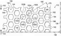
图2是示出可以与清创工具110的一些实施例相关的额外细节的平面图。清创工具110可以包括通过清创工具110延伸的多个孔140或穿孔,以形成通过清创工具110延伸的多个壁148。在一些实施例中,这些壁148可以平行于清创工具110的厚度134。在其他实施例中,这些壁148可以大体上垂直于清创工具110的面向组织表面111和相反表面113。在一些实施例中,孔140可以具有所示的一个六边形形状。在其他实施例中,孔140可以具有圆形、椭圆性、三角形、正方形、不规则形状或无定形。FIG. 2 is a plan view showing additional details that may be associated with some embodiments of the
在一些实施例中,清创工具110可以具有第一标定线136和垂直于第一标定线136的第二标定线138。第一标定线136和第二标定线138可以是清创工具110的对称线。对称线可以是例如穿过清创工具110的面向组织表面111或相反表面113的虚线,它定义了一条折线以使得如果清创工具110折叠在对称线上,则孔140和壁148将同时对齐。总体上,第一标定线136和第二标定线138有助于描述清创工具110。在一些实施例中,第一标定线136和第二标定线138可以用于指代清创工具110希望的收缩方向。例如,希望的收缩方向可以平行于第二标定线138并垂直于第一标定线136。在其他实施例中,希望的收缩方向可以平行于第一标定线136并垂直于第二标定线138。在其他实施例中,希望的收缩方向可以与第一标定线136和第二标定线138成非垂直角度。总体上,清创工具110可以置于组织部位103,以使得第二标定线138延伸穿过图1的腐肉130和焦痂132。In some embodiments, the
尽管清创工具110被示出为具有包括纵向边缘144和纬向边缘146的大致矩形,但是清创工具110也可以具有其他形状。例如,清创工具110可以具有菱形、正方形或圆形形状。在一些实施例中,清创工具110的形状可以被选择为适应有待治疗的组织部位的类型。例如,清创工具110可以具有适应椭圆形或圆形组织部位的一个椭圆形或圆形形状。在一些实施例中,第一标定线136可以平行于纵向边缘144。Although the
更确切地说参见图3,示出了具有一个六边形形状的单个孔140。孔140可以包括一个中心150和一个周长152。孔140可以具有一个穿孔形状系数(PSF)。穿孔形状系数(PSF)可以表示孔140相对于第一标定线136和第二标定线138的定向。总体上,穿孔形状系数(PSF)是孔140平行于希望的收缩方向的1/2最大长度与孔140垂直于希望的收缩方向的1/2最大长度的比率。出于描述目的,希望的收缩方向平行于第二标定线138。希望的收缩方向可以由清创力142所指示。作为参考,孔140可以具有通过中心150在六边形的相对顶点之间延伸并平行于第一标定线136的X-轴156和通过中心150在六边形的相对顶点之间延伸并平行于第二标定线138的Y-轴154。孔140的穿孔形状系数(PSF)可以被定义为在Y-轴154上从中心150延伸到孔140的周长152的线段158与在X-轴156上从中心150延伸到孔140的周长152的线段160的比率。如果线段158的长度是2.69mm并且线段160的长度是2.5mm,则穿孔形状系数(PSF)将是2.69/2.5或约1.08。在其他实施例中,孔140可以相对于第一标定线136和第二标定线138定向,以使得穿孔形状系数(PSF)可以是约1.07或1.1。Referring more specifically to Figure 3, a
参考图4,示出了图1的清创工具110的一部分。清创工具110可以包括平行行图案对齐的多个孔140。平行行图案可以包括孔140的第一行162、孔140的第二行164、以及孔140的第三行166。在相邻行例如第一行162和第二行164中的孔140的中心150的特征是沿着第一标定线136偏离第二标定线138。在一些实施例中,连接相邻行的中心的一条线可以与第一标定线136形成支柱角度(SA)。例如,在第一行162中的第一孔140A可以具有一个中心150A,并且在第二行164中的第二孔140B可以具有一个中心150B。支柱线168可以连接中心150A与中心150B。支柱线168可以与第一标定线136形成一个角度170。角度170可以是清创工具110的支柱角度(SA)。在一些实施例中,支柱角度(SA)可以小于约90°。在其他实施例中,支柱角度(SA)可以是在相对于第一标定线136约30°与约70°之间。在其他实施例中,支柱角度(SA)可以是相对于第一标定线136约66°。总体上,随着支柱角度(SA)减小,清创工具110在平行于第一标定线136的方向中的刚度可以减小。增加清创工具110平行于第一标定线136的刚度可以增加清创工具110垂直于第一标定线136的可压缩性。因此,如果将负压施加于清创工具110,则清创工具110可以在垂直于第一标定线136的方向中具有更大的适应性或可压缩性。通过增加清创工具110在垂直于第一标定线136的方向中的可压缩性,清创工具110可以塌陷来将清创力142施加于组织部位103,如在下文中更详细描述的。Referring to Figure 4, a portion of the
在一些实施例中,在交替行中的孔140的中心150例如在第一行162中的第一孔140A的中心150A和在第三行166中的孔140C的中心150C由长度172平行于第二标定线138而彼此间隔。在一些实施例中,长度172可以大于孔140的有效直径。如果在交替行中的孔140的中心150被长度172分开,则平行于第一标定线136的壁148可以被认为是连续的。总体上,如果壁148在孔140之间不具有间断或断裂,则壁148可以是连续的。In some embodiments, the
不管孔140的形状如何,在清创工具110中的孔140可以在清创工具110中并且在清创工具110的面向组织表面111和相反表面113上留下空隙空间,以使得仅清创工具110的壁148属于可用于接触组织部位103的表面。可能希望的是使壁148最小化,以使得孔140可以塌陷,从而引起清创工具110塌陷并在垂直于第一标定线136的方向中生成清创力142。然而,也可能希望壁148未最小化太多,以致于清创工具110对于维持负压的施加而言太脆。孔140的空隙空间百分比(VS)可以等于由孔140产生的面向组织表面111的空隙空间的容积或表面积相对于清创工具110的面向组织表面111的总容积或表面积的百分比。在一些实施例中,空隙空间百分比(VS)可以是在约40%与约60%之间。在其他实施例中,空隙空间百分比(VS)可以是约55%。Regardless of the shape of the
在一些实施例中,这些孔140可以在清创工具110的模塑过程中形成。在其他实施例中,孔140可以是在清创工具110形成之后通过切割、熔化或汽化清创工具110来形成。例如,孔140可以是通过激光切割清创工具110的压缩泡沫而在清创工具110中形成。在一些实施例中,孔140的有效直径可以被选择为允许微粒流动通过孔140。非圆形区域的有效直径被定义为具有与非圆形区域相同的表面积的圆形区域的直径。在一些实施例中,每个孔140可以具有约3.5mm的有效直径。在其他实施例中,每个孔140可以具有约5mm与约20mm之间的有效直径。孔140的有效直径应与形成清创工具110的壁148的材料孔隙度区分。总体上,孔140的有效直径的数量级大于形成清创工具110的材料的孔隙的有效直径。例如,孔140的有效直径可以大于约1mm,而壁148可以由具有小于约600微米的孔隙大小的
现在参考图2和图4,孔140可以根据孔140的几何形状和清创工具110中的相邻行和交替行之间的孔140相对于第一标定线136的对齐而形成一个图案。如果清创工具110经受负压,则清创工具110的孔140可以塌陷。在一些实施例中,空隙空间百分比(VS)、穿孔形状系数(PSF)和支柱角度(SA)可以引起清创工具110沿着垂直于第一标定线136的第二标定线138收缩,如图5中更详细示出的。如果清创工具110被定位在组织部位103上,则清创工具110可以沿着第二标定线138生成清创力142,从收缩清创工具110,如图5中更详细示出的。清创力142可以是通过如以下表1所陈述地调整上述系数来优化。在一些实施例中,孔140可以是六边形的,具有约66°的支柱角度(SA)、约55%的空隙空间百分比(VS)、约5的硬度系数(FF)、约1.07的穿孔形状系数(PSF)、以及约5mm的有效直径。如果清创工具110经受约-125mmHg负压,则由清创工具110施加的清创力142是约13.3N。如果清创工具110的孔140的有效直径被增加至10mm,则清创力142被减小至约7.5N。Referring now to FIGS. 2 and 4 , the
参考图5,清创工具110处于第二位置或者收缩位置,如清创力142所指示的。在操作中,通过负压源104将负压施加于密封治疗环境128。响应于负压的施加,清创工具110从图2所示的松弛位置收缩至图5所示的收缩位置。总体上,清创工具110的厚度134基本上保持相同。当例如通过排空负压来移除负压后,清创工具110膨胀回到松弛位置。如果清创工具110分别在图5的收缩位置和图2的松弛位置之间循环,则清创工具110的面向组织表面111通过从创伤切除死亡或污染组织(包括腐肉130和焦痂132)来对组织部位103进行清创。通过面向组织表面111和壁148的横向表面形成的孔140的边缘形成对组织部位103进行清创的切割边缘,从而允许切下的组织在施加负压后通过孔140和歧管108排入到容器112中。在一些实施例中,切割边缘通过周长152限定,其中每个孔140贯穿面向组织表面111。Referring to FIG. 5 , the
在一些实施例中,治疗系统100可以提供循环治疗。循环治疗可以交替地施加负压于密封治疗环境128和从该密封治疗环境中排空负压。在一些实施例中,负压可以施加于密封治疗环境128,直到密封治疗环境128中的压力达到预定治疗压力为止。如果负压施加于密封治疗环境128,则清创工具110如图5所示地收缩。在一些实施例中,密封治疗环境128可以在治疗压力下保持预定治疗时间段,例如像约10分钟。在其他实施例中,治疗时间段可以比需要的时间更长或更短,以将适当负压施加于组织部位103。In some embodiments, the
在治疗时段之后,可以排空密封治疗环境128。例如,负压源104可以将密封治疗环境128流体联接至大气(未示出)中,从而允许密封治疗环境128恢复至环境压力。在一些实施例中,负压源104可以将密封治疗环境128排空约1分钟。在其他实施例中,负压源104可以将密封治疗环境128排空更长或更短的时间段。响应于通过排空密封治疗环境128来使密封治疗环境128恢复至环境压力,清创工具110膨胀,从而恢复到图2的松弛位置。清创工具110的收缩和膨胀引起清创工具110的切割边缘对如上所述的组织部位103进行清创。当通过负压源104将负压施加于密封治疗环境128时去除的切下组织部分(包括腐肉130和焦痂132)可以通过孔140抽出。After the treatment period, the sealed
在一些实施例中,滴注治疗可以与负压治疗组合。举例来说,在负压治疗的治疗时间段之后,流体源120可以运行来将流体提供给密封治疗环境128。在一些实施例中,流体源120可以提供流体,而负压源104排空密封治疗环境128。例如,流体源120可以包括配置用于将滴注流体从流体源120移动到密封治疗环境128的一个泵。在其他实施例中,负压源104可以不排空密封治疗环境128。相反,在密封治疗环境128中的负压用于将滴注流体从流体源120抽入到密封治疗环境128中。In some embodiments, infusion therapy may be combined with negative pressure therapy. For example, after a treatment period of negative pressure therapy, the
在一些实施例中,流体源120可以将一定体积的流体提供到密封治疗环境128中。在一些实施例中,该流体体积可以与密封治疗环境128的体积相同。在其他实施例中,根据需要,该流体体积可以小于或大于密封治疗环境128,以适当地应用滴注治疗。在一些实施例中,由流体源120提供的流体可以在密封治疗环境128中保持一定停留时间。在一些实施例中,停留时间是约5分钟。在其他实施例中,停留时间可以比需要的时间更长或更短,以将滴注治疗适当地施用至组织部位103。停留时间可以被称为治疗循环的停留时间。In some embodiments,
在停留时间结束后,负压源104可以被运行来将滴注流体抽入到容器112中,从而完成一个治疗循环。随着滴注流体通过负压从密封治疗环境128中去除,负压也可以施加至密封治疗环境128中,从而开始另一个治疗循环。After the dwell time has elapsed, the
在由负压源104提供的每个治疗循环中,清创工具110可以收缩并膨胀。通过每个治疗循环,清创工具110的面向组织表面111通过清创力142摩擦穿过组织部位103的面对表面。清创工具110通过清创力142进行的摩擦作用引起孔140的切割边缘驱除腐肉130和焦痂132的部分。通过每个随后的治疗循环,通过清创力142从组织部位103除去另外的腐肉130和焦痂132部分。驱除的颗粒状腐肉130和焦痂132部分可以足够小到能通过负压治疗从组织部位103抽出。如果还提供滴注治疗,则来自流体源120的流体也可以有助于去除已清除的组织。滴注治疗还可以清洁歧管108,从而防止歧管108被去除的腐肉130和焦痂132堵塞。During each treatment cycle provided by the
图6是示出可以与清创工具210的一些实施例相关的额外细节的平面图。清创工具210可以类似于清创工具110并且如以上相对于图1-图5所述地运行。类似元件可以具有索引至200的类似参考号。举例来说,清创工具210被示出为具有包括纵向边缘244和纬向边缘246的大致矩形。清创工具210可以具有第一标定线236和垂直于第一标定线236的第二标定线238。在一些实施例中,第一标定线236和第二标定线238可以用于指代清创工具210希望的收缩方向。例如,希望的收缩方向可以平行于第二标定线238并垂直于第一标定线236,如通过清创力142所示的。在其他实施例中,希望的收缩方向可以垂直于第二标定线238并平行于第一标定线236。在其他实施例中,希望的收缩方向可以与第二标定线238和第一标定线236成非垂直的。总体上,清创工具210可以置于组织部位103处,以使得清创工具210的面向组织表面211可以覆盖组织部位103具有腐肉130或焦痂132的部分。清创工具210可以包括通过清创工具210延伸的多个孔240或穿孔,以形成通过清创工具210延伸的多个壁248。在一些实施例中,这些壁248平行于清创工具210的厚度234。这些壁248可以具有与面向组织表面211交叉以形成切割边缘的横向表面。在一些实施例中,孔240可以具有所示的一个圆形形状。FIG. 6 is a plan view showing additional details that may be associated with some embodiments of the
更确切地说参见图7,示出了具有一个圆形形状的单个孔240。孔240可以包括一个中心250、一个周长252和一个穿孔形状系数(PSF)。作为参考,孔240可以具有通过中心250延伸的平行于第一标定线236的X-轴256和通过中心250延伸的平行于第二标定线238的Y-轴254。在一些实施例中,孔240的穿孔形状系数(PSF)可以被定义为在Y-轴254上从中心250延伸到孔240的周长252的线段258与在X-轴256上从中心250延伸到孔240的周长252的线段260的比率。如果线段258的长度是2.5mm并且线段260的长度是2.5mm,则穿孔形状系数(PSF)将是2.5/2.5或约1。Referring more specifically to Figure 7, a
参考图8,示出了图6的清创工具210的一部分。清创工具210可以包括平行行图案对齐的多个孔240。平行行图案可以包括孔240的第一行262、孔240的第二行264、以及孔240的第三行266。图7的每个孔240的X-轴256可以平行于图8的第一标定线236。在相邻行例如第一行262和第二行264中的孔240的中心250的特征是沿着第一标定线236偏离第二标定线238。在一些实施例中,连接相邻行的中心的一条线可以与第一标定线236形成支柱角度(SA)。例如,在第一行262中的第一孔240A可以具有一个中心250A,并且在第二行264中的第二孔240B可以具有一个中心250B。支柱线268可以连接中心250A与中心250B。支柱线268可以与第一标定线236形成一个角度270。角度270可以是清创工具210的支柱角度(SA)。在一些实施例中,支柱角度(SA)可以小于约90°。在其他实施例中,支柱角度(SA)可以是在相对于第一标定线236约30°与约70°之间。如上所述的,如果将负压施加于清创工具210,则清创工具210可以在垂直于第一标定线236的方向中具有更大的适应性或可压缩性。通过增加清创工具210在垂直于第一标定线236的方向中的可压缩性,清创工具210可以塌陷来将清创力施加于组织部位103,如在下文中更详细描述的。Referring to Figure 8, a portion of the
在一些实施例中,在交替行中的孔240的中心250例如在第一行262中的第一孔240A的中心250A和在第三行266中的孔240C的中心250C由长度272平行于第二标定线238而彼此间隔。在一些实施例中,长度272可以大于孔240的有效直径。如果在交替行中的孔240的中心250被长度272分开,则平行于第一标定线236的壁248可以被认为是连续的。总体上,如果壁248在孔240之间不具有不连续处或断裂,则壁248可以是连续的。In some embodiments, the
不管孔240的形状如何,在清创工具210中的孔240可以在清创工具210中并且在清创工具210的面向组织表面211上留下空隙空间,以使得仅清创工具210的壁248属于可用于接触组织部位103的表面。可能希望的是使壁248最小化,以使得孔240塌陷,从而引起清创工具210塌陷以在垂直于第一标定线236的方向中生成清创力142。然而,也可能希望壁248未最小化太多,以致于清创工具210对于维持负压施加而言太脆。孔240的空隙空间百分比(VS)可以等于由孔240产生的面向组织表面211的空隙空间的容积或表面积相对于清创工具210的面向组织表面211的总容积或表面积的百分比。在一些实施例中,空隙空间百分比(VS)可以是在约40%与约60%之间。在其他实施例中,空隙空间百分比(VS)可以是约54%。Regardless of the shape of the
在一些实施例中,孔240的直径可以被选择为允许微粒流动通过孔240。在一些实施例中,每个孔240可以具有约5mm的直径。在其他实施例中,每个孔240可以具有约3.5mm与约20mm之间的有效直径。In some embodiments, the diameter of the
现在参考图7和图8,孔240可以根据孔240的几何形状和清创工具210中的相邻行和交替行之间的孔240相对于第一标定线236的对齐而形成一个图案。如果清创工具210经受负压,则清创工具210的孔240可以塌陷。在一些实施例中,空隙空间百分比(VS)、穿孔形状系数(PSF)和支柱角度(SA)可以引起清创工具210沿着垂直于第一标定线236的第二标定线238塌陷。清创力142可以是通过如以下表1所陈述地调整上述系数来优化。在一些实施例中,孔240可以是圆形的,具有约37°的支柱角度(SA)、约54%的空隙空间百分比(VS)、约5的硬度系数(FF)、约1的穿孔形状系数(PSF)、以及约5mm的直径。如果清创工具210经受约-125mmHg的负压,则清创工具210施加约11.9N的清创力142。如果清创工具210的孔240的直径增加至约20mm,则空隙百分比(VS)变成约52%,支柱角度(SA)变成约52°,并且穿孔形状系数(PSF)和硬度系数(FF)保持相同,清创力142减小至约6.5N。Referring now to FIGS. 7 and 8 , the
图9A是示出可以与清创工具310的一些实施例相关的额外细节的平面图。清创工具310可以类似于清创工具110并且如以上相对于图1-图5所述地运行。类似元件可以具有索引至300的类似参考编号。清创工具310可以覆盖组织部位103。在一些实施例中,清创工具310可以具有第一标定线336和垂直于第一标定线336的第二标定线338。在一些实施例中,第一标定线336和第二标定线338可以用于指代清创工具310希望的收缩方向。例如,希望的收缩方向可以平行于第二标定线338并垂直于第一标定线336。在其他实施例中,希望的收缩方向可以垂直于第二标定线338并平行于第一标定线336。在其他实施例中,希望的收缩方向可以与第二标定线338和第一标定线336成非垂直角度。总体上,清创工具310可以置于组织部位103处,以使得清创工具310的面向组织表面311可以覆盖组织部位103具有腐肉130和焦痂132的部分。清创工具310可以包括通过清创工具310延伸的多个孔340或穿孔,以形成通过清创工具310延伸的多个壁348。在一些实施例中,这些壁348平行于清创工具310的厚度334。这些壁348可以具有与面向组织表面311交叉以形成切割边缘的横向表面。在一些实施例中,孔340可以具有所示的一个卵形形状。FIG. 9A is a plan view illustrating additional details that may be associated with some embodiments of
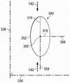
更确切地说参见图10,示出了具有一个卵形形状的单个孔340。孔340可以包括一个中心350、一个周长352和一个穿孔形状系数(PSF)。作为参考,孔340可以具有通过中心350延伸的平行于第一标定线336的X-轴356和通过中心350延伸的平行于第二标定线338的Y-轴354。在一些实施例中,孔340的穿孔形状系数(PSF)可以被定义为在Y-轴354上从中心350延伸到孔340的周长352的线段358与在X-轴356上从中心350延伸到孔340的周长352的线段360的比率。如果线段358的长度是2.5mm并且线段360的长度是2.5mm,则穿孔形状系数(PSF)将是2.5/2.5或约1。Referring more specifically to Figure 10, a
参考图11,如果孔340相对于第一标定线336和第二标定线338旋转,以使得孔340的主轴平行于第二标定线338并且孔340的短轴平行于第一标定线336,则穿孔形状系数(PSF)可以发生变化。举例来说,穿孔形状系数(PSF)现在被定义为在Y-轴354上从中心350延伸到孔340的周长352的线段376与在X-轴356上从中心350延伸到孔340的周长352的线段378的比率。如果线段376的长度是5mm并且线段378的长度是2.5mm,则穿孔形状系数(PSF)将是5/2.5或约2。11, if the
参考图12,如果孔340相对于第一标定线336和第二标定线338旋转,以使得孔340的主轴平行于第一标定线336并且孔340的短轴平行于第二标定线338,则穿孔形状系数(PSF)可以发生变化。举例来说,穿孔形状系数(PSF)现在被定义为在Y-轴354上从中心350延伸到孔340的周长352的线段380与在X-轴356上从中心350延伸到孔340的周长352的线段382的比率。如果线段380的长度是2.5mm并且线段382的长度是5mm,则穿孔形状系数(PSF)将是2.5/5或约1/2。Referring to FIG. 12, if the
参考图9B,示出了图9A的清创工具310的一部分。清创工具310可以包括平行行图案对齐的多个孔340。平行行图案可以包括孔340的第一行362、孔340的第二行364、以及孔340的第三行366。图10、图11和图12的每个孔340的X-轴356可以平行于图9B的第一标定线336。在相邻行例如第一行362和第二行364中的孔340的中心350的特征是沿着第一标定线336偏离第二标定线338。在一些实施例中,连接相邻行的中心的一条线可以与第一标定线336形成支柱角度(SA)。例如,在第一行362中的第一孔340A可以具有一个中心350A,并且在第二行364中的第二孔340B可以具有一个中心350B。支柱线368可以连接中心350A与中心350B。支柱线368可以与第一标定线336形成一个角度370。角度370可以是清创工具310的支柱角度(SA)。在一些实施例中,支柱角度(SA)可以小于约90°。在其他实施例中,支柱角度(SA)可以是在相对于第一标定线336约30°与约70°之间。如上所述的,如果将负压施加于清创工具310,则清创工具310可以在垂直于第一标定线336的方向中具有更大的适应性或可压缩性。通过增加清创工具310在垂直于第一标定线336的方向中的可压缩性,清创工具310可以塌陷来将清创力142施加于组织部位103,如在下文中更详细描述的。Referring to Figure 9B, a portion of the
在一些实施例中,在交替行中的孔340的中心350例如在第一行362中的第一孔340A的中心350A和在第三行366中的孔340C的中心350C由长度372平行于第二标定线338而彼此间隔。在一些实施例中,长度372可以大于孔340的有效直径。如果在交替行中的孔340的中心350被长度372分开,则平行于第一标定线336的壁348可以被认为是连续的。总体上,如果壁348在孔340之间不具有不连续处或断裂,则壁348可以是连续的。In some embodiments, the
不管孔340的形状如何,在清创工具310中的孔340可以在清创工具310中并且在清创工具310的面向组织表面311上留下空隙空间,以使得仅清创工具310的壁348属于可用于接触组织部位103的表面。可能希望的是使壁348最小化,以使得孔340可以塌陷,从而引起清创工具310塌陷,在垂直于第一标定线336的方向中生成清创力142。然而,也可能希望壁348未最小化太多,以致于清创工具310对于维持负压施加而言太脆。孔340的空隙空间百分比(VS)可以等于由孔340产生的面向组织表面311的空隙空间的容积或表面积相对于清创工具310的面向组织表面311的总容积或表面积的百分比。在一些实施例中,空隙空间百分比(VS)可以是在约40%与约60%之间。在其他实施例中,空隙空间百分比(VS)可以是约56%。Regardless of the shape of the
在一些实施例中,孔340的有效直径可以被选择为允许微粒流动通过孔340。在一些实施例中,每个孔340可以具有约7mm的有效直径。在其他实施例中,每个孔340可以具有约2.5mm与约20mm之间的有效直径。In some embodiments, the effective diameter of the
现在参考图9A和图9B,孔340可以根据孔340的几何形状和清创工具310中的相邻行和交替行之间的孔340相对于第一标定线336的对齐而形成一个图案。如果清创工具310经受负压,则清创工具310的孔340可以塌陷,引起清创工具310沿着垂直于第一标定线336的第二标定线338塌陷。如果清创工具310被定位在组织部位103上,则清创工具310可以沿着第二标定线338生成清创力142,以使得清创工具310在相同方向中收缩以对组织部位103进行清创。清创力142可以是通过如以下表1所陈述地调整上述系数来优化。在一些实施例中,孔340可以是卵形的,具有约47°的支柱角度(SA)、约56%的空隙空间百分比(VS)、约5的硬度系数(FF)、约1的穿孔形状系数(PSF)、以及约7mm的有效直径(其中主轴是约10mm并且短轴是约5mm)。如果清创工具310经受约-125mmHg的负压,则清创工具310施加约13.5N的清创力142。Referring now to FIGS. 9A and 9B , the
图13A是示出可以与清创工具410的一些实施例相关的额外细节的平面图。清创工具410可以类似于清创工具110并且如相对于图1-图5所述地运行。类似元件可以具有索引至400的类似参考编号。举例来说,清创工具410被示出为具有包括纵向边缘444和纬向边缘446的大致矩形。清创工具410可以覆盖组织部位103。在一些实施例中,清创工具410可以具有第一标定线436和垂直于第一标定线436的第二标定线438。在一些实施例中,第一标定线436和第二标定线438可以用于指代清创工具410希望的收缩方向。例如,希望的收缩方向可以平行于第二标定线438并垂直于第一标定线436。在其他实施例中,希望的收缩方向可以垂直于第二标定线438并平行于第一标定线436。在其他实施例中,希望的收缩方向可以与第二标定线438和第一标定线436成非垂直角度。总体上,清创工具410可以置于组织部位103处,以使得清创工具410的面向组织表面411可以覆盖组织部位103具有腐肉130或焦痂132的部分。清创工具410可以包括通过清创工具410延伸的多个孔440或穿孔,以形成通过清创工具410延伸的多个壁448。在一些实施例中,这些壁448平行于清创工具410的厚度434。这些壁448可以具有与面向组织表面411交叉以形成切割边缘的横向表面。在一些实施例中,孔440可以具有所示的一个三角形形状。FIG. 13A is a plan view showing additional details that may be associated with some embodiments of
更确切地说参见图14,示出了具有一个三角形形状的单个孔440。孔440可以包括一个中心450、一个周长452和一个穿孔形状系数(PSF)。在一些实施例,孔440可以包括一个第一顶点484、一个第二顶点486和一个第三顶点488。作为参考,孔440可以具有通过中心450延伸的平行于第一标定线436的X-轴456和通过中心450延伸的平行于第二标定线438的Y-轴454。在一些实施例中,孔440的穿孔形状系数(PSF)可以被定义为在Y-轴454上从中心450延伸到孔440的周长452的线段458与在X-轴456上从中心450延伸到孔440的周长452的线段460的比率。如果线段458的长度是1.1mm并且线段460的长度是1mm,则穿孔形状系数(PSF)将是1.1/1或约1.1。Referring more specifically to Figure 14, a
参考图13B,示出了图13A的清创工具410的一部分。清创工具410可以包括平行行图案对齐的多个孔440。平行行图案可以包括孔440的第一行462、孔440的第二行464、以及孔440的第三行466。图14的每个孔440的X-轴456可以平行于图13B的第一标定线436。在一些实施例中,在第一行462的第一孔440A可以被定向来使得第一顶点484A可以是在第一标定线436与和第一顶点484A相反的第一孔440A的一边之间。与第一行462的第一孔440A相邻的孔440C可以被定向来使得第一顶点484C可以与第一孔440A相对地定向。Referring to Figure 13B, a portion of the
在相邻行例如第一行462和第二行464中具有在同一方向中定向的第一顶点484的孔440的中心450的特征是沿着第一标定线436偏离第二标定线438。在一些实施例中,连接相邻行的中心450的一条线可以与第一标定线436形成支柱角度(SA)。例如,在第一行462中的第一孔440A可以具有一个中心450A,并且在第二行464中的第二孔440B可以具有一个中心450B和一个第一顶点484B。支柱线468可以连接中心450A与中心450B。支柱线468可以与第一标定线436形成一个角度470。角度470可以是清创工具410的支柱角度(SA)。在一些实施例中,支柱角度(SA)可以小于约90°。在其他实施例中,支柱角度(SA)可以是在相对于第一标定线436约40°与约70°之间。如上所述的,如果将负压施加于清创工具410,则清创工具410可以在垂直于第一标定线436的方向中具有更大的适应性或可压缩性。通过增加清创工具410在垂直于第一标定线436的方向中的可压缩性,清创工具410可以塌陷来将清创力142施加于组织部位103,如在下文中更详细描述的。
不管孔440的形状如何,在清创工具410中的孔440可以在清创工具410中并且在清创工具410的面向组织表面411上留下空隙空间,以使得仅清创工具410的壁448属于可用于接触组织部位103的表面。可能希望的是使壁448最小化,以使得孔440可以塌陷,从而引起清创工具410塌陷,以在垂直于第一标定线436的方向中生成清创力142。然而,也可能希望壁448未最小化太多,以致于清创工具410对于维持负压施加而言太脆。孔440的空隙空间百分比(VS)可以等于由孔440产生的面向组织表面411的空隙空间的容积或表面积相对于清创工具410的面向组织表面411的总容积或表面积的百分比。在一些实施例中,空隙空间百分比(VS)可以是在约40%与约60%之间。在其他实施例中,空隙空间百分比(VS)可以是约56%。Regardless of the shape of the
在一些实施例中,孔440的有效直径可以被选择为允许微粒流动通过孔440。在一些实施例中,每个孔440可以具有约7mm的有效直径。在其他实施例中,每个孔440可以具有约2.5mm与约20mm之间的有效直径。In some embodiments, the effective diameter of the
现在参考图13A和图13B,孔440可以根据孔440的几何形状和清创工具410中的相邻行和交替行之间的孔440相对于第一标定线436的对齐而形成一个图案。如果清创工具410经受负压,则清创工具410的孔440可以塌陷。在一些实施例中,空隙空间百分比(VS)、穿孔形状系数(PSF)和支柱角度(SA)可以引起清创工具410沿着垂直于第一标定线436的第二标定线438塌陷。如果清创工具410被定位在组织部位103上,则清创工具410可以沿着第二标定线438生成清创力142,以使得清创工具410在相同方向中收缩。清创力142可以是通过如以下表1所陈述地调整上述系数来优化。在一些实施例中,孔440可以是三角形的,具有约63°的支柱角度(SA)、约40%的空隙空间百分比(VS)、约5的硬度系数(FF)、约1.1的穿孔形状系数(PSF)、以及约10mm的有效直径。如果清创工具410经受约-125mmHg的负压,则清创工具410可以施加约13.5N的清创力142。Referring now to FIGS. 13A and 13B , the
图15是示出可以与清创工具510的一些实施例相关的额外细节的平面图。清创工具510可以类似于如以上相对于图1-图5所述的清创工具110。清创工具510可以包括条纹516和条纹518。在一些实施例中,清创工具510可由一种类似于
通过清创工具诸如清创工具110生成的清创力诸如清创力142可以与通过向密封治疗环境施加治疗压力下的负压来生成的压缩力相关。例如,清创力142可以与密封治疗环境128中的治疗压力(TP)、清创工具110的压缩系数(CF)和清创工具110的面向组织表面111的表面积(A)的乘积成比例。关系表示如下:A debridement force, such as
清创力α(TP*CF*A)Debridement α(TP*CF*A)
在一些实施例中,治疗压力TP是以N/m2测量,压缩系数(CF)是无量纲的,面积(A)是以m2测量的,并且清创力是以牛顿(N)测量的。由将负压施加于清创工具而产生的压缩系数(CF)可以是例如与清创工具的空隙空间百分比(VS)、清创工具的硬度系数(FF)、清创工具中孔的支柱角度(SA)、以及清创工具中孔的穿孔形状系数(PSF)的乘积成比例的无量纲数。关系表示如下:In some embodiments, treatment pressure TP is measured in N/m, compressibility (CF) is dimensionless, area (A) is measured in m, and debridement force is measured in Newtons (N) . The compressibility (CF) resulting from applying negative pressure to the debridement tool can be, for example, the void space percentage (VS) relative to the debridement tool, the stiffness factor (FF) of the debridement tool, the strut angle of the hole in the debridement tool (SA), and a dimensionless number proportional to the product of the perforation shape factor (PSF) of the hole in the debridement tool. The relationship is expressed as follows:
压缩系数(CF)α(VS*FF*sin(SA)*PSF)Compression factor (CF)α(VS*FF*sin(SA)*PSF)
基于以上公式,制造并测试由具有不同形状的孔的不同材料形成的清创工具,以测定清创工具的清创力。对于每种清创工具,治疗压力TP是约-125mmHg并且清创工具的尺寸是约200mm乘以53mm,以使得清创工具的面向组织表面的表面积(A)是约106cm2或0.0106m2。基于上述两个等式,具有3的硬度系数(FF)的


在一些实施例中,上述公式不能精确描述清创力,因为力从清创工具转移到创伤而有所损失。例如,覆盖件106的模量和伸缩、组织部位103的模量、覆盖件106在组织部位103上的滑动、以及清创工具110与组织部位103之间的摩擦可以引起清创力142的实际值小于清创力142的计算值。In some embodiments, the above formulas do not accurately describe debridement force because force is lost from the transfer of force from the debridement tool to the wound. For example, the modulus and expansion of the
在此描述的这些系统、设备和方法可以提供多个显著优点。例如,将清创工具的机械摩擦作用与滴注的水合和冲洗作用以及负压治疗组合可以实现组织部位的低疼或无痛清创。在此所述的清创工具与其他机械清创方法和酶促清创方法相比也可需要更少临床医师或其他值班员的监测。另外,如在此所述的清创工具当在组织部位自溶清创过程中进行时不会被去除的坏死组织所阻断。The systems, devices, and methods described herein can provide a number of significant advantages. For example, combining the mechanical frictional effects of debridement tools with the hydration and irrigation effects of instillation and negative pressure therapy can achieve low or painless debridement of tissue sites. The debridement tools described herein may also require less clinician or other on-call monitoring than other mechanical and enzymatic methods of debridement. Additionally, the debridement tool as described herein is not blocked by necrotic tissue removed when performed during autolytic debridement of a tissue site.
尽管在一些说明性实施例中示出,但是本领域普通技术人员将认识到在此描述的这些系统、装置和方法易于作出不同的变化和修改。此外,除非上下文清楚地要求,否则使用诸如“或”的术语的不同替代方案的描述不需要相互排斥,并且除非上下文清楚地要求,否则不定冠词“一个”或“一种”不将主题限制为单个实例。Although shown in some illustrative embodiments, those of ordinary skill in the art will recognize that the systems, apparatus, and methods described herein are susceptible to various changes and modifications. Furthermore, the description of different alternatives using terms such as "or" need not be mutually exclusive unless the context clearly requires it, and the indefinite articles "a" or "an" do not limit the subject matter unless the context clearly requires it for a single instance.
所附权利要求书阐述上文所述的主题的多个新颖性和发明性方面,但是权利要求书还可以涵盖未详细明确列举的另外的主题。例如,如果不必将这些新颖性和发明性特征与本领域普通技术人员已知的来进行区分,某些特征、元件或方面可以从权利要求书中省略掉。在此所述的特征、元件和方面还可以组合或者被用于相同、等同或类似目的的替代性特征替换而不背离由所附权利要求书所定义的发明范围。The appended claims set forth various novel and inventive aspects of the above-described subject matter, but the claims may also cover additional subject matter not expressly recited in detail. For example, certain features, elements or aspects may be omitted from the claims if it is not necessary to distinguish these novel and inventive features from what is known to one of ordinary skill in the art. The features, elements and aspects described herein may also be combined or replaced by alternative features serving the same, equivalent or similar purpose without departing from the scope of the invention as defined by the appended claims.
Claims (43)
Translated fromChinesePriority Applications (2)
| Application Number | Priority Date | Filing Date | Title |
|---|---|---|---|
| CN202010088181.3ACN111134779B (en) | 2014-05-09 | 2015-05-08 | Debridement dressings for use with negative pressure and fluid instillation |
| CN202310381589.3ACN116370035A (en) | 2014-05-09 | 2015-05-08 | Debridement dressings for use with negative pressure and fluid instillation |
Applications Claiming Priority (3)
| Application Number | Priority Date | Filing Date | Title |
|---|---|---|---|
| US201461991134P | 2014-05-09 | 2014-05-09 | |
| US61/991,134 | 2014-05-09 | ||
| PCT/US2015/030023WO2015172104A1 (en) | 2014-05-09 | 2015-05-08 | Debriding dressing for use with negative pressure and fluid instillation |
Related Child Applications (2)
| Application Number | Title | Priority Date | Filing Date |
|---|---|---|---|
| CN202310381589.3ADivisionCN116370035A (en) | 2014-05-09 | 2015-05-08 | Debridement dressings for use with negative pressure and fluid instillation |
| CN202010088181.3ADivisionCN111134779B (en) | 2014-05-09 | 2015-05-08 | Debridement dressings for use with negative pressure and fluid instillation |
Publications (2)
| Publication Number | Publication Date |
|---|---|
| CN106456848A CN106456848A (en) | 2017-02-22 |
| CN106456848Btrue CN106456848B (en) | 2020-03-06 |
Family
ID=53267627
Family Applications (3)
| Application Number | Title | Priority Date | Filing Date |
|---|---|---|---|
| CN202010088181.3AActiveCN111134779B (en) | 2014-05-09 | 2015-05-08 | Debridement dressings for use with negative pressure and fluid instillation |
| CN201580026901.0AActiveCN106456848B (en) | 2014-05-09 | 2015-05-08 | Debridement dressings for use with negative pressure and fluid instillation |
| CN202310381589.3APendingCN116370035A (en) | 2014-05-09 | 2015-05-08 | Debridement dressings for use with negative pressure and fluid instillation |
Family Applications Before (1)
| Application Number | Title | Priority Date | Filing Date |
|---|---|---|---|
| CN202010088181.3AActiveCN111134779B (en) | 2014-05-09 | 2015-05-08 | Debridement dressings for use with negative pressure and fluid instillation |
Family Applications After (1)
| Application Number | Title | Priority Date | Filing Date |
|---|---|---|---|
| CN202310381589.3APendingCN116370035A (en) | 2014-05-09 | 2015-05-08 | Debridement dressings for use with negative pressure and fluid instillation |
Country Status (7)
| Country | Link |
|---|---|
| US (3) | US10143485B2 (en) |
| EP (4) | EP3821858B1 (en) |
| JP (2) | JP6728062B2 (en) |
| CN (3) | CN111134779B (en) |
| AU (3) | AU2015255719B2 (en) |
| CA (1) | CA2947298C (en) |
| WO (1) | WO2015172104A1 (en) |
Families Citing this family (83)
| Publication number | Priority date | Publication date | Assignee | Title |
|---|---|---|---|---|
| US9421132B2 (en) | 2011-02-04 | 2016-08-23 | University Of Massachusetts | Negative pressure wound closure device |
| WO2013066426A2 (en) | 2011-06-24 | 2013-05-10 | Kci Licensing, Inc. | Reduced-pressure dressings employing tissue-fixation elements |
| AU2013264937B2 (en) | 2012-05-24 | 2018-04-19 | Smith & Nephew Inc. | Devices and methods for treating and closing wounds with negative pressure |
| MX369689B (en) | 2012-07-16 | 2019-11-19 | Smith & Nephew Inc | Negative pressure wound closure device. |
| US10124098B2 (en) | 2013-03-13 | 2018-11-13 | Smith & Nephew, Inc. | Negative pressure wound closure device and systems and methods of use in treating wounds with negative pressure |
| CN106170275B (en) | 2013-10-21 | 2021-05-07 | 史密夫和内修有限公司 | Negative pressure wound closure device |
| WO2015172111A1 (en)* | 2014-05-09 | 2015-11-12 | Kci Licensing, Inc. | Disruptive dressing for use with negative pressure and fluid instillation |
| US10898217B2 (en) | 2014-05-09 | 2021-01-26 | Kci Licensing, Inc. | Dressing providing apertures with multiple orifice sizes for negative-pressure therapy |
| WO2015172108A1 (en) | 2014-05-09 | 2015-11-12 | Kci Licensing, Inc. | Dressing with contracting layer for linear tissue sites |
| DK3288508T3 (en) | 2015-04-27 | 2020-03-09 | Smith & Nephew | REDUCED PRESSURE DEVICES |
| AU2016254119A1 (en) | 2015-04-29 | 2017-10-05 | Smith & Nephew Inc. | Negative pressure wound closure device |
| US11471586B2 (en) | 2015-12-15 | 2022-10-18 | University Of Massachusetts | Negative pressure wound closure devices and methods |
| EP3426206B1 (en) | 2016-03-07 | 2023-05-10 | Smith & Nephew plc | Wound treatment apparatuses and methods with negative pressure source integrated into wound dressing |
| US11167074B2 (en) | 2016-03-17 | 2021-11-09 | Kcl Licensing, Inc. | Systems and methods for treating a tissue site using one manifold and multiple therapy units |
| CA3022184A1 (en) | 2016-04-26 | 2017-11-02 | Smith & Nephew Plc | Wound dressings and methods of use with integrated negative pressure source having a fluid ingress inhibition component |
| CA3038206A1 (en) | 2016-05-03 | 2017-11-09 | Smith & Nephew Plc | Optimizing power transfer to negative pressure sources in negative pressure therapy systems |
| WO2017191158A1 (en) | 2016-05-03 | 2017-11-09 | Smith & Nephew Plc | Systems and methods for driving negative pressure sources in negative pressure therapy systems |
| US11096831B2 (en) | 2016-05-03 | 2021-08-24 | Smith & Nephew Plc | Negative pressure wound therapy device activation and control |
| WO2018037075A1 (en) | 2016-08-25 | 2018-03-01 | Smith & Nephew Plc | Absorbent negative pressure wound therapy dressing |
| US11096832B2 (en) | 2016-09-27 | 2021-08-24 | Smith & Nephew Plc | Wound closure devices with dissolvable portions |
| EP3519001B1 (en) | 2016-09-30 | 2025-05-21 | Smith & Nephew plc | Negative pressure wound treatment apparatuses and methods with integrated electronics |
| CN110167495B (en) | 2016-11-02 | 2022-06-14 | 史密夫和内修有限公司 | Wound closure device |
| EP3551244A1 (en) | 2016-12-12 | 2019-10-16 | Smith & Nephew PLC | Pressure wound therapy status indication via external device |
| EP3592312B1 (en) | 2017-03-08 | 2024-01-10 | Smith & Nephew plc | Negative pressure wound therapy device control in presence of fault condition |
| JP7121050B2 (en) | 2017-05-09 | 2022-08-17 | スミス アンド ネフュー ピーエルシー | Redundant control of negative pressure wound therapy systems |
| WO2018226650A1 (en) | 2017-06-07 | 2018-12-13 | Kci Licensing, Inc. | Systems, apparatuses, and methods for negative-pressure treatment with reduced tissue in-growth |
| WO2018226691A1 (en) | 2017-06-07 | 2018-12-13 | Kci Licensing, Inc. | Methods for manufacturing and assembling dual material tissue interface for negative-pressure therapy |
| WO2018226707A1 (en) | 2017-06-07 | 2018-12-13 | Kci Licensing, Inc. | Composite dressings for improved granulation reduced maceration with negative-pressure treatment |
| AU2018282159A1 (en) | 2017-06-07 | 2019-12-19 | 3M Innovative Properties Company | Composite dressings for improved granulation and reduced maceration with negative-pressure treatment |
| JP7204685B2 (en) | 2017-06-07 | 2023-01-16 | スリーエム イノベイティブ プロパティズ カンパニー | A composite dressing that promotes granulation formation and reduces maceration in negative pressure therapy |
| WO2018226744A1 (en) | 2017-06-07 | 2018-12-13 | Kci Licensing, Inc. | Peel and place dressing for negative -pressure treatment |
| EP3634334B1 (en) | 2017-06-07 | 2023-05-24 | 3M Innovative Properties Company | Multi-layer wound filler for extended wear time |
| US10695227B2 (en) | 2017-06-07 | 2020-06-30 | Kci Licensing, Inc. | Methods for manufacturing and assembling dual material tissue interface for negative-pressure therapy |
| AU2018282188A1 (en) | 2017-06-07 | 2019-12-19 | 3M Innovative Properties Company | Tissue contact interface |
| WO2018229009A1 (en) | 2017-06-13 | 2018-12-20 | Smith & Nephew Plc | Wound closure device and method of use |
| EP3638169B1 (en) | 2017-06-13 | 2024-11-13 | Smith & Nephew PLC | Collapsible structure and method of use |
| US11123476B2 (en) | 2017-06-14 | 2021-09-21 | Smith & Nephew, Inc. | Fluid removal management and control of wound closure in wound therapy |
| WO2018231874A1 (en) | 2017-06-14 | 2018-12-20 | Smith & Nephew, Inc. | Control of wound closure and fluid removal management in wound therapy |
| AU2018285239B2 (en) | 2017-06-14 | 2023-09-21 | Smith & Nephew Plc | Collapsible sheet for wound closure and method of use |
| WO2018229011A1 (en) | 2017-06-14 | 2018-12-20 | Smith & Nephew Plc | Collapsible structure for wound closure and method of use |
| WO2019020544A1 (en) | 2017-07-27 | 2019-01-31 | Smith & Nephew Plc | Customizable wound closure device and method of use |
| US11590030B2 (en) | 2017-08-07 | 2023-02-28 | Smith & Nephew Plc | Wound closure device with protective layer and method of use |
| EP3675925A1 (en) | 2017-08-29 | 2020-07-08 | Smith & Nephew PLC | Systems and methods for monitoring wound closure |
| GB201718070D0 (en) | 2017-11-01 | 2017-12-13 | Smith & Nephew | Negative pressure wound treatment apparatuses and methods with integrated electronics |
| CA3074780A1 (en) | 2017-09-13 | 2019-03-21 | Smith & Nephew Plc | Negative pressure wound treatment apparatuses and methods with integrated electronics |
| RU2020113361A (en)* | 2017-09-20 | 2021-10-20 | Колопласт А/С | WOUND CARE DEVICE TO REMOVE DEAD TISSUE OF WOUNDS |
| US11432967B2 (en)* | 2017-10-23 | 2022-09-06 | Kci Licensing, Inc. | Fluid bridge for simultaneous application of negative pressure to multiple tissue sites |
| WO2019084006A1 (en) | 2017-10-23 | 2019-05-02 | Kci Licensing, Inc. | Low profile distribution components for wound therapy |
| JP7288901B2 (en)* | 2017-10-24 | 2023-06-08 | スリーエム イノベイティブ プロパティズ カンパニー | Wound dressing for debridement and system using same |
| GB201718054D0 (en) | 2017-11-01 | 2017-12-13 | Smith & Nephew | Sterilization of integrated negative pressure wound treatment apparatuses and sterilization methods |
| GB201718072D0 (en) | 2017-11-01 | 2017-12-13 | Smith & Nephew | Negative pressure wound treatment apparatuses and methods with integrated electronics |
| US11497653B2 (en) | 2017-11-01 | 2022-11-15 | Smith & Nephew Plc | Negative pressure wound treatment apparatuses and methods with integrated electronics |
| US20210077302A1 (en)* | 2018-01-04 | 2021-03-18 | Kci Licensing, Inc. | Peel And Place Dressing For Thick Exudate And Instillation |
| EP3735211B1 (en)* | 2018-01-04 | 2024-03-13 | Solventum Intellectual Properties Company | Peel and place dressing for thick exudate and instillation |
| US10624794B2 (en) | 2018-02-12 | 2020-04-21 | Healyx Labs, Inc. | Negative pressure wound therapy systems, devices, and methods |
| WO2019164618A1 (en)* | 2018-02-23 | 2019-08-29 | Kci Licensing, Inc. | Dressing with bolster for linear tissue sites |
| US11040127B2 (en) | 2018-04-09 | 2021-06-22 | Kci Licensing, Inc. | Abdominal dressing with mechanism for fascial closure |
| USD878609S1 (en) | 2018-04-09 | 2020-03-17 | Kci Licensing, Inc. | Compressive layer for abdominal wound dressing |
| EP3801416B1 (en)* | 2018-05-25 | 2024-07-10 | Solventum Intellectual Properties Company | Method and system for providing active tissue site debridement |
| US12053205B2 (en)* | 2018-05-25 | 2024-08-06 | Solventum Intellectual Properties Company | Method and system for providing active tissue site debridement |
| US12178687B2 (en) | 2018-05-25 | 2024-12-31 | Solventum Intellectual Properties Company | Method and system for providing active tissue site debridement |
| EP3829515A1 (en)* | 2018-08-01 | 2021-06-09 | KCI Licensing, Inc. | Soft-tissue treatment with negative pressure |
| CN112423800B (en) | 2018-08-03 | 2024-05-17 | 3M创新知识产权公司 | Wound treatment system with wound volume estimation |
| EP3840794B1 (en) | 2018-08-21 | 2023-10-11 | 3M Innovative Properties Company | System for utilizing pressure decay to determine available fluid capacity in a negative pressure dressing |
| USD898925S1 (en) | 2018-09-13 | 2020-10-13 | Smith & Nephew Plc | Medical dressing |
| WO2020056014A1 (en)* | 2018-09-14 | 2020-03-19 | Kci Licensing, Inc. | Differential collapse wound dressings |
| USD961782S1 (en) | 2018-10-23 | 2022-08-23 | Kci Licensing, Inc. | Low-profile fluid conductor for tissue therapy |
| JP7566755B2 (en)* | 2019-01-24 | 2024-10-15 | スリーエム イノベイティブ プロパティズ カンパニー | Variable density dressing |
| EP3914308B1 (en)* | 2019-01-25 | 2024-05-15 | Solventum Intellectual Properties Company | Systems for instillation purging |
| GB201903774D0 (en) | 2019-03-20 | 2019-05-01 | Smith & Nephew | Negative pressure wound treatment apparatuses and methods with integrated electronics |
| EP3946502A1 (en) | 2019-03-29 | 2022-02-09 | KCI Licensing, Inc. | Dressing with integrated pump and releasably coupled pump actuator |
| WO2020205445A1 (en)* | 2019-03-29 | 2020-10-08 | Kci Licensing, Inc. | Negative-pressure treatment with area stabilization |
| GB201907716D0 (en) | 2019-05-31 | 2019-07-17 | Smith & Nephew | Systems and methods for extending operational time of negative pressure wound treatment apparatuses |
| CN110338867A (en)* | 2019-06-26 | 2019-10-18 | 万绵水 | Electrostatic spinning Wound dressing and its processing method containing dihydroquercetin |
| WO2020263473A1 (en)* | 2019-06-26 | 2020-12-30 | Kci Licensing, Inc. | Dressing including differential lateral contraction capability |
| EP4007552B1 (en)* | 2019-08-01 | 2025-03-19 | Solventum Intellectual Properties Company | Hand dressing for use with negative pressure wound therapy |
| US12409072B2 (en) | 2019-12-05 | 2025-09-09 | Kci Manufacturing Unlimited Company | Multi-layer negative pressure incisional wound therapy dressing |
| US20220409801A1 (en)* | 2019-12-13 | 2022-12-29 | Kci Licensing, Inc. | Conformable dressing for negative-pressure treatment of large areas |
| JP2023536800A (en)* | 2020-07-09 | 2023-08-30 | ケーシーアイ ライセンシング インコーポレイテッド | Tissue interface for tissue debridement |
| CN116547017A (en)* | 2020-08-21 | 2023-08-04 | 凯希制造无限公司 | Wound interface system with integral contact surface |
| EP4251110A4 (en)* | 2020-11-24 | 2024-10-23 | Aroa Biosurgery Limited | BANDAGE |
| JP2024518367A (en) | 2021-05-06 | 2024-05-01 | ケーシーアイ マニュファクチャリング アンリミテッド カンパニー | Bioabsorbable, dispersible, rapidly deployable wound interface |
| CN114622334B (en)* | 2022-04-29 | 2024-01-23 | 青岛全季服饰有限公司 | Breathable ultraviolet-proof fabric and preparation method thereof |
Citations (4)
| Publication number | Priority date | Publication date | Assignee | Title |
|---|---|---|---|---|
| US20090093779A1 (en)* | 2006-04-12 | 2009-04-09 | Birgit Riesinger | Primary Dressing |
| US20100063484A1 (en)* | 2008-09-05 | 2010-03-11 | Tyco Healthcare Group Lp | Three-Dimensional Porous Film Contact Layer With Improved Wound Healing |
| US20140066868A1 (en)* | 2011-11-01 | 2014-03-06 | J&M Shuler Medical, Inc. | Mechanical wound therapy for sub-atmospheric wound care system |
| CN103747814A (en)* | 2011-08-31 | 2014-04-23 | 凯希特许有限公司 | Reduced pressure therapy and debridement systems and methods |
Family Cites Families (145)
| Publication number | Priority date | Publication date | Assignee | Title |
|---|---|---|---|---|
| US1355846A (en) | 1920-02-06 | 1920-10-19 | David A Rannells | Medical appliance |
| US2547758A (en) | 1949-01-05 | 1951-04-03 | Wilmer B Keeling | Instrument for treating the male urethra |
| US2632443A (en) | 1949-04-18 | 1953-03-24 | Eleanor P Lesher | Surgical dressing |
| GB692578A (en) | 1949-09-13 | 1953-06-10 | Minnesota Mining & Mfg | Improvements in or relating to drape sheets for surgical use |
| US2682873A (en) | 1952-07-30 | 1954-07-06 | Johnson & Johnson | General purpose protective dressing |
| NL189176B (en) | 1956-07-13 | 1900-01-01 | Hisamitsu Pharmaceutical Co | PLASTER BASED ON A SYNTHETIC RUBBER. |
| US2969057A (en) | 1957-11-04 | 1961-01-24 | Brady Co W H | Nematodic swab |
| US3066672A (en) | 1960-09-27 | 1962-12-04 | Jr William H Crosby | Method and apparatus for serial sampling of intestinal juice |
| US3367332A (en) | 1965-08-27 | 1968-02-06 | Gen Electric | Product and process for establishing a sterile area of skin |
| US3520300A (en) | 1967-03-15 | 1970-07-14 | Amp Inc | Surgical sponge and suction device |
| US3568675A (en) | 1968-08-30 | 1971-03-09 | Clyde B Harvey | Fistula and penetrating wound dressing |
| US3682180A (en) | 1970-06-08 | 1972-08-08 | Coilform Co Inc | Drain clip for surgical drain |
| BE789293Q (en) | 1970-12-07 | 1973-01-15 | Parke Davis & Co | MEDICO-SURGICAL DRESSING FOR BURNS AND SIMILAR LESIONS |
| US3826254A (en) | 1973-02-26 | 1974-07-30 | Verco Ind | Needle or catheter retaining appliance |
| DE2527706A1 (en) | 1975-06-21 | 1976-12-30 | Hanfried Dr Med Weigand | DEVICE FOR THE INTRODUCTION OF CONTRAST AGENTS INTO AN ARTIFICIAL INTESTINAL OUTLET |
| DE2640413C3 (en) | 1976-09-08 | 1980-03-27 | Richard Wolf Gmbh, 7134 Knittlingen | Catheter monitor |
| NL7710909A (en) | 1976-10-08 | 1978-04-11 | Smith & Nephew | COMPOSITE STRAPS. |
| GB1562244A (en) | 1976-11-11 | 1980-03-05 | Lock P M | Wound dressing materials |
| US4080970A (en) | 1976-11-17 | 1978-03-28 | Miller Thomas J | Post-operative combination dressing and internal drain tube with external shield and tube connector |
| US4139004A (en) | 1977-02-17 | 1979-02-13 | Gonzalez Jr Harry | Bandage apparatus for treating burns |
| US4184510A (en) | 1977-03-15 | 1980-01-22 | Fibra-Sonics, Inc. | Valued device for controlling vacuum in surgery |
| US4165748A (en) | 1977-11-07 | 1979-08-28 | Johnson Melissa C | Catheter tube holder |
| US4245637A (en) | 1978-07-10 | 1981-01-20 | Nichols Robert L | Shutoff valve sleeve |
| SE414994B (en) | 1978-11-28 | 1980-09-01 | Landstingens Inkopscentral | VENKATETERFORBAND |
| GB2047543B (en) | 1978-12-06 | 1983-04-20 | Svedman Paul | Device for treating tissues for example skin |
| US4266545A (en) | 1979-04-06 | 1981-05-12 | Moss James P | Portable suction device for collecting fluids from a closed wound |
| US4284079A (en) | 1979-06-28 | 1981-08-18 | Adair Edwin Lloyd | Method for applying a male incontinence device |
| US4261363A (en) | 1979-11-09 | 1981-04-14 | C. R. Bard, Inc. | Retention clips for body fluid drains |
| US4569348A (en) | 1980-02-22 | 1986-02-11 | Velcro Usa Inc. | Catheter tube holder strap |
| WO1981002516A1 (en) | 1980-03-11 | 1981-09-17 | E Schmid | Cushion for holding an element of grafted skin |
| US4297995A (en) | 1980-06-03 | 1981-11-03 | Key Pharmaceuticals, Inc. | Bandage containing attachment post |
| US4333468A (en) | 1980-08-18 | 1982-06-08 | Geist Robert W | Mesentery tube holder apparatus |
| US4465485A (en) | 1981-03-06 | 1984-08-14 | Becton, Dickinson And Company | Suction canister with unitary shut-off valve and filter features |
| US4392853A (en) | 1981-03-16 | 1983-07-12 | Rudolph Muto | Sterile assembly for protecting and fastening an indwelling device |
| US4373519A (en) | 1981-06-26 | 1983-02-15 | Minnesota Mining And Manufacturing Company | Composite wound dressing |
| US4392858A (en) | 1981-07-16 | 1983-07-12 | Sherwood Medical Company | Wound drainage device |
| US4419097A (en) | 1981-07-31 | 1983-12-06 | Rexar Industries, Inc. | Attachment for catheter tube |
| AU550575B2 (en) | 1981-08-07 | 1986-03-27 | Richard Christian Wright | Wound drainage device |
| SE429197B (en) | 1981-10-14 | 1983-08-22 | Frese Nielsen | SAR TREATMENT DEVICE |
| DE3146266A1 (en) | 1981-11-21 | 1983-06-01 | B. Braun Melsungen Ag, 3508 Melsungen | COMBINED DEVICE FOR A MEDICAL SUCTION DRAINAGE |
| US4551139A (en) | 1982-02-08 | 1985-11-05 | Marion Laboratories, Inc. | Method and apparatus for burn wound treatment |
| US4475909A (en) | 1982-05-06 | 1984-10-09 | Eisenberg Melvin I | Male urinary device and method for applying the device |
| EP0100148B1 (en) | 1982-07-06 | 1986-01-08 | Dow Corning Limited | Medical-surgical dressing and a process for the production thereof |
| NZ206837A (en) | 1983-01-27 | 1986-08-08 | Johnson & Johnson Prod Inc | Thin film adhesive dressing:backing material in three sections |
| US4548202A (en) | 1983-06-20 | 1985-10-22 | Ethicon, Inc. | Mesh tissue fasteners |
| US4540412A (en) | 1983-07-14 | 1985-09-10 | The Kendall Company | Device for moist heat therapy |
| US4543100A (en) | 1983-11-01 | 1985-09-24 | Brodsky Stuart A | Catheter and drain tube retainer |
| US4525374A (en) | 1984-02-27 | 1985-06-25 | Manresa, Inc. | Treating hydrophobic filters to render them hydrophilic |
| CA1286177C (en) | 1984-05-03 | 1991-07-16 | Smith And Nephew Associated Companies Plc | Adhesive wound dressing |
| US4897081A (en) | 1984-05-25 | 1990-01-30 | Thermedics Inc. | Percutaneous access device |
| US5215522A (en) | 1984-07-23 | 1993-06-01 | Ballard Medical Products | Single use medical aspirating device and method |
| GB8419745D0 (en) | 1984-08-02 | 1984-09-05 | Smith & Nephew Ass | Wound dressing |
| US4872450A (en) | 1984-08-17 | 1989-10-10 | Austad Eric D | Wound dressing and method of forming same |
| US4826494A (en) | 1984-11-09 | 1989-05-02 | Stryker Corporation | Vacuum wound drainage system |
| US4655754A (en) | 1984-11-09 | 1987-04-07 | Stryker Corporation | Vacuum wound drainage system and lipids baffle therefor |
| US4605399A (en) | 1984-12-04 | 1986-08-12 | Complex, Inc. | Transdermal infusion device |
| US5037397A (en) | 1985-05-03 | 1991-08-06 | Medical Distributors, Inc. | Universal clamp |
| US4640688A (en) | 1985-08-23 | 1987-02-03 | Mentor Corporation | Urine collection catheter |
| US4710165A (en) | 1985-09-16 | 1987-12-01 | Mcneil Charles B | Wearable, variable rate suction/collection device |
| US4758220A (en) | 1985-09-26 | 1988-07-19 | Alcon Laboratories, Inc. | Surgical cassette proximity sensing and latching apparatus |
| US4733659A (en) | 1986-01-17 | 1988-03-29 | Seton Company | Foam bandage |
| EP0256060A1 (en) | 1986-01-31 | 1988-02-24 | OSMOND, Roger L. W. | Suction system for wound and gastro-intestinal drainage |
| US4838883A (en) | 1986-03-07 | 1989-06-13 | Nissho Corporation | Urine-collecting device |
| JPS62281965A (en) | 1986-05-29 | 1987-12-07 | テルモ株式会社 | Catheter and catheter fixing member |
| GB8621884D0 (en) | 1986-09-11 | 1986-10-15 | Bard Ltd | Catheter applicator |
| GB2195255B (en) | 1986-09-30 | 1991-05-01 | Vacutec Uk Limited | Apparatus for vacuum treatment of an epidermal surface |
| US4743232A (en) | 1986-10-06 | 1988-05-10 | The Clinipad Corporation | Package assembly for plastic film bandage |
| DE3634569A1 (en) | 1986-10-10 | 1988-04-21 | Sachse Hans E | CONDOM CATHETER, A URINE TUBE CATHETER FOR PREVENTING RISING INFECTIONS |
| JPS63135179A (en) | 1986-11-26 | 1988-06-07 | 立花 俊郎 | Subcataneous drug administration set |
| GB8628564D0 (en) | 1986-11-28 | 1987-01-07 | Smiths Industries Plc | Anti-foaming agent suction apparatus |
| GB8706116D0 (en) | 1987-03-14 | 1987-04-15 | Smith & Nephew Ass | Adhesive dressings |
| US4787888A (en) | 1987-06-01 | 1988-11-29 | University Of Connecticut | Disposable piezoelectric polymer bandage for percutaneous delivery of drugs and method for such percutaneous delivery (a) |
| US4863449A (en) | 1987-07-06 | 1989-09-05 | Hollister Incorporated | Adhesive-lined elastic condom cathether |
| US5176663A (en) | 1987-12-02 | 1993-01-05 | Pal Svedman | Dressing having pad with compressibility limiting elements |
| US4906240A (en) | 1988-02-01 | 1990-03-06 | Matrix Medica, Inc. | Adhesive-faced porous absorbent sheet and method of making same |
| US4985019A (en) | 1988-03-11 | 1991-01-15 | Michelson Gary K | X-ray marker |
| GB8812803D0 (en) | 1988-05-28 | 1988-06-29 | Smiths Industries Plc | Medico-surgical containers |
| US4919654A (en) | 1988-08-03 | 1990-04-24 | Kalt Medical Corporation | IV clamp with membrane |
| US5000741A (en) | 1988-08-22 | 1991-03-19 | Kalt Medical Corporation | Transparent tracheostomy tube dressing |
| US5059596A (en) | 1989-01-16 | 1991-10-22 | Roussel Uclaf | Azabicyclo compounds |
| GB8906100D0 (en) | 1989-03-16 | 1989-04-26 | Smith & Nephew | Laminates |
| US4969880A (en) | 1989-04-03 | 1990-11-13 | Zamierowski David S | Wound dressing and treatment method |
| US5261893A (en) | 1989-04-03 | 1993-11-16 | Zamierowski David S | Fastening system and method |
| US5100396A (en) | 1989-04-03 | 1992-03-31 | Zamierowski David S | Fluidic connection system and method |
| US5527293A (en) | 1989-04-03 | 1996-06-18 | Kinetic Concepts, Inc. | Fastening system and method |
| JP2719671B2 (en) | 1989-07-11 | 1998-02-25 | 日本ゼオン株式会社 | Wound dressing |
| US5358494A (en) | 1989-07-11 | 1994-10-25 | Svedman Paul | Irrigation dressing |
| US5232453A (en) | 1989-07-14 | 1993-08-03 | E. R. Squibb & Sons, Inc. | Catheter holder |
| GB2235877A (en) | 1989-09-18 | 1991-03-20 | Antonio Talluri | Closed wound suction apparatus |
| US5134994A (en) | 1990-02-12 | 1992-08-04 | Say Sam L | Field aspirator in a soft pack with externally mounted container |
| US5092858A (en) | 1990-03-20 | 1992-03-03 | Becton, Dickinson And Company | Liquid gelling agent distributor device |
| US5149331A (en) | 1991-05-03 | 1992-09-22 | Ariel Ferdman | Method and device for wound closure |
| US5278100A (en) | 1991-11-08 | 1994-01-11 | Micron Technology, Inc. | Chemical vapor deposition technique for depositing titanium silicide on semiconductor wafers |
| US5645081A (en) | 1991-11-14 | 1997-07-08 | Wake Forest University | Method of treating tissue damage and apparatus for same |
| US5636643A (en) | 1991-11-14 | 1997-06-10 | Wake Forest University | Wound treatment employing reduced pressure |
| US5279550A (en) | 1991-12-19 | 1994-01-18 | Gish Biomedical, Inc. | Orthopedic autotransfusion system |
| US5167613A (en) | 1992-03-23 | 1992-12-01 | The Kendall Company | Composite vented wound dressing |
| FR2690617B1 (en) | 1992-04-29 | 1994-06-24 | Cbh Textile | TRANSPARENT ADHESIVE DRESSING. |
| DE4306478A1 (en) | 1993-03-02 | 1994-09-08 | Wolfgang Dr Wagner | Drainage device, in particular pleural drainage device, and drainage method |
| US5342376A (en) | 1993-05-03 | 1994-08-30 | Dermagraphics, Inc. | Inserting device for a barbed tissue connector |
| US6241747B1 (en) | 1993-05-03 | 2001-06-05 | Quill Medical, Inc. | Barbed Bodily tissue connector |
| US5344415A (en) | 1993-06-15 | 1994-09-06 | Deroyal Industries, Inc. | Sterile system for dressing vascular access site |
| US5437651A (en) | 1993-09-01 | 1995-08-01 | Research Medical, Inc. | Medical suction apparatus |
| US5549584A (en) | 1994-02-14 | 1996-08-27 | The Kendall Company | Apparatus for removing fluid from a wound |
| US5556375A (en) | 1994-06-16 | 1996-09-17 | Hercules Incorporated | Wound dressing having a fenestrated base layer |
| US5607388A (en) | 1994-06-16 | 1997-03-04 | Hercules Incorporated | Multi-purpose wound dressing |
| US5664270A (en) | 1994-07-19 | 1997-09-09 | Kinetic Concepts, Inc. | Patient interface system |
| DE69505545T2 (en) | 1994-08-22 | 1999-03-11 | Kinetic Concepts Inc | WOUND DRAINAGE DEVICE |
| DE29504378U1 (en) | 1995-03-15 | 1995-09-14 | MTG Medizinisch, technische Gerätebau GmbH, 66299 Friedrichsthal | Electronically controlled low-vacuum pump for chest and wound drainage |
| GB9523253D0 (en) | 1995-11-14 | 1996-01-17 | Mediscus Prod Ltd | Portable wound treatment apparatus |
| US6135116A (en) | 1997-07-28 | 2000-10-24 | Kci Licensing, Inc. | Therapeutic method for treating ulcers |
| AU755496B2 (en) | 1997-09-12 | 2002-12-12 | Kci Licensing, Inc. | Surgical drape and suction head for wound treatment |
| GB9719520D0 (en) | 1997-09-12 | 1997-11-19 | Kci Medical Ltd | Surgical drape and suction heads for wound treatment |
| US6071267A (en) | 1998-02-06 | 2000-06-06 | Kinetic Concepts, Inc. | Medical patient fluid management interface system and method |
| US6488643B1 (en) | 1998-10-08 | 2002-12-03 | Kci Licensing, Inc. | Wound healing foot wrap |
| US6287316B1 (en) | 1999-03-26 | 2001-09-11 | Ethicon, Inc. | Knitted surgical mesh |
| US7799004B2 (en) | 2001-03-05 | 2010-09-21 | Kci Licensing, Inc. | Negative pressure wound treatment apparatus and infection identification system and method |
| US6856821B2 (en) | 2000-05-26 | 2005-02-15 | Kci Licensing, Inc. | System for combined transcutaneous blood gas monitoring and vacuum assisted wound closure |
| US6991643B2 (en) | 2000-12-20 | 2006-01-31 | Usgi Medical Inc. | Multi-barbed device for retaining tissue in apposition and methods of use |
| US6387103B2 (en) | 1999-12-30 | 2002-05-14 | Aq Technologies, Inc. | Instruments and techniques for inducing neocollagenesis in skin treatments |
| ES2220734T3 (en) | 2000-02-24 | 2004-12-16 | Venetec International, Inc. | UNIVERSAL FIXING SYSTEM FOR CATETER. |
| GB0011202D0 (en)* | 2000-05-09 | 2000-06-28 | Kci Licensing Inc | Abdominal wound dressing |
| US6685681B2 (en)* | 2000-11-29 | 2004-02-03 | Hill-Rom Services, Inc. | Vacuum therapy and cleansing dressing for wounds |
| US6540705B2 (en) | 2001-02-22 | 2003-04-01 | Core Products International, Inc. | Ankle brace providing upper and lower ankle adjustment |
| US7247161B2 (en)* | 2002-03-22 | 2007-07-24 | Gyrus Ent L.L.C. | Powered surgical apparatus, method of manufacturing powered surgical apparatus, and method of using powered surgical apparatus |
| GB0224986D0 (en)* | 2002-10-28 | 2002-12-04 | Smith & Nephew | Apparatus |
| US7951124B2 (en)* | 2004-04-13 | 2011-05-31 | Boehringer Technologies, Lp | Growth stimulating wound dressing with improved contact surfaces |
| US8529548B2 (en) | 2004-04-27 | 2013-09-10 | Smith & Nephew Plc | Wound treatment apparatus and method |
| US20070299369A1 (en)* | 2006-06-26 | 2007-12-27 | Eilaz Babaev | Ultrasound wound care device and method |
| NZ573820A (en)* | 2006-07-07 | 2010-10-29 | Boehringer Technologies Lp | Wound dressing having voids that are large and resistant to collapse for encouraging cellular growth |
| US8057446B2 (en)* | 2007-05-01 | 2011-11-15 | The Brigham And Women's Hospital, Inc. | Wound healing device |
| RU2447878C2 (en)* | 2007-06-29 | 2012-04-20 | КейСиАй Лайсензинг Инк. | Osteogenesis and chondrogenesis activation |
| WO2009021523A1 (en)* | 2007-08-14 | 2009-02-19 | Coloplast A/S | Pressure-distributing element of closed cell foam |
| US9023001B2 (en)* | 2007-09-12 | 2015-05-05 | Heal-Ex, Llc | Systems and methods for providing a debriding wound vacuum |
| US8257326B2 (en)* | 2008-06-30 | 2012-09-04 | Tyco Healthcare Group Lp | Apparatus for enhancing wound healing |
| US8486032B2 (en)* | 2008-12-24 | 2013-07-16 | Kci Licensing, Inc. | Reduced-pressure treatment systems and methods employing debridement mechanisms |
| US8162907B2 (en)* | 2009-01-20 | 2012-04-24 | Tyco Healthcare Group Lp | Method and apparatus for bridging from a dressing in negative pressure wound therapy |
| JP5414098B2 (en)* | 2009-03-30 | 2014-02-12 | ユニ・チャーム株式会社 | Disposable diapers |
| US20110144674A1 (en)* | 2009-10-16 | 2011-06-16 | Keith Patrick Heaton | Debridement cutting heads, methods, and systems employing reduced pressure |
| US8702644B2 (en)* | 2010-05-13 | 2014-04-22 | Ethicon Endo-Surgery, Inc. | Instrument for debriding tissue and applying therapeutic cells |
| WO2012078556A2 (en)* | 2010-12-07 | 2012-06-14 | Kci Licensing, Inc. | Wound healing apparatus for promoting granulation and epithelialisation at a tissue site |
| AU2012212070A1 (en)* | 2011-02-04 | 2013-09-19 | University Of Massachusetts | Negative pressure wound closure device |
| WO2013066426A2 (en)* | 2011-06-24 | 2013-05-10 | Kci Licensing, Inc. | Reduced-pressure dressings employing tissue-fixation elements |
| MX369689B (en)* | 2012-07-16 | 2019-11-19 | Smith & Nephew Inc | Negative pressure wound closure device. |
| EP3096725B1 (en)* | 2014-01-21 | 2023-10-18 | Smith & Nephew plc | Wound treatment apparatuses |
- 2015
- 2015-05-08JPJP2016566815Apatent/JP6728062B2/enactiveActive
- 2015-05-08EPEP20212298.2Apatent/EP3821858B1/enactiveActive
- 2015-05-08EPEP19164841.9Apatent/EP3527180B1/enactiveActive
- 2015-05-08USUS14/708,078patent/US10143485B2/enactiveActive
- 2015-05-08EPEP17186252.7Apatent/EP3263078B1/enactiveActive
- 2015-05-08CNCN202010088181.3Apatent/CN111134779B/enactiveActive
- 2015-05-08CNCN201580026901.0Apatent/CN106456848B/enactiveActive
- 2015-05-08CACA2947298Apatent/CA2947298C/enactiveActive
- 2015-05-08AUAU2015255719Apatent/AU2015255719B2/enactiveActive
- 2015-05-08WOPCT/US2015/030023patent/WO2015172104A1/enactiveApplication Filing
- 2015-05-08EPEP15724880.8Apatent/EP3139879B1/enactiveActive
- 2015-05-08CNCN202310381589.3Apatent/CN116370035A/enactivePending
- 2018
- 2018-10-23USUS16/168,446patent/US20190053819A1/enactivePending
- 2019
- 2019-12-17AUAU2019283817Apatent/AU2019283817B2/enactiveActive
- 2020
- 2020-07-01JPJP2020113823Apatent/JP7090667B2/enactiveActive
- 2021
- 2021-09-14AUAU2021232704Apatent/AU2021232704B2/enactiveActive
- 2023
- 2023-12-13USUS18/538,282patent/US20240109849A1/enactivePending
Patent Citations (4)
| Publication number | Priority date | Publication date | Assignee | Title |
|---|---|---|---|---|
| US20090093779A1 (en)* | 2006-04-12 | 2009-04-09 | Birgit Riesinger | Primary Dressing |
| US20100063484A1 (en)* | 2008-09-05 | 2010-03-11 | Tyco Healthcare Group Lp | Three-Dimensional Porous Film Contact Layer With Improved Wound Healing |
| CN103747814A (en)* | 2011-08-31 | 2014-04-23 | 凯希特许有限公司 | Reduced pressure therapy and debridement systems and methods |
| US20140066868A1 (en)* | 2011-11-01 | 2014-03-06 | J&M Shuler Medical, Inc. | Mechanical wound therapy for sub-atmospheric wound care system |
Also Published As
| Publication number | Publication date |
|---|---|
| EP3263078A1 (en) | 2018-01-03 |
| AU2015255719B2 (en) | 2019-09-19 |
| US10143485B2 (en) | 2018-12-04 |
| US20240109849A1 (en) | 2024-04-04 |
| JP7090667B2 (en) | 2022-06-24 |
| JP2017517312A (en) | 2017-06-29 |
| AU2019283817B2 (en) | 2021-06-17 |
| AU2015255719A1 (en) | 2016-11-03 |
| AU2021232704A1 (en) | 2021-10-21 |
| EP3527180B1 (en) | 2021-01-06 |
| CN111134779B (en) | 2023-04-18 |
| CA2947298C (en) | 2023-06-06 |
| EP3527180A1 (en) | 2019-08-21 |
| EP3263078B1 (en) | 2019-05-08 |
| AU2021232704B2 (en) | 2023-03-16 |
| AU2019283817A1 (en) | 2020-01-16 |
| CN111134779A (en) | 2020-05-12 |
| CN116370035A (en) | 2023-07-04 |
| EP3139879B1 (en) | 2017-08-23 |
| EP3821858A1 (en) | 2021-05-19 |
| US20150320603A1 (en) | 2015-11-12 |
| CN106456848A (en) | 2017-02-22 |
| EP3139879A1 (en) | 2017-03-15 |
| US20190053819A1 (en) | 2019-02-21 |
| WO2015172104A1 (en) | 2015-11-12 |
| JP2020168425A (en) | 2020-10-15 |
| EP3821858B1 (en) | 2024-06-26 |
| CA2947298A1 (en) | 2015-11-12 |
| JP6728062B2 (en) | 2020-07-22 |
Similar Documents
| Publication | Publication Date | Title |
|---|---|---|
| CN106456848B (en) | Debridement dressings for use with negative pressure and fluid instillation | |
| US12408939B2 (en) | Disruptive dressing for use with negative pressure and fluid instillation | |
| EP3876885B1 (en) | Wound dressing with semi-rigid support to increase disruption using perforated dressing and negative pressure wound therapy | |
| JP2023536800A (en) | Tissue interface for tissue debridement |
Legal Events
| Date | Code | Title | Description |
|---|---|---|---|
| C06 | Publication | ||
| PB01 | Publication | ||
| SE01 | Entry into force of request for substantive examination | ||
| SE01 | Entry into force of request for substantive examination | ||
| GR01 | Patent grant | ||
| GR01 | Patent grant | ||
| TR01 | Transfer of patent right | Effective date of registration:20210527 Address after:American Minnesota Patentee after:3M innovation intellectual property Co. Address before:Texas, USA Patentee before:KCI LICENSING, Inc. | |
| TR01 | Transfer of patent right | ||
| TR01 | Transfer of patent right | Effective date of registration:20240408 Address after:U.S.A. Patentee after:Shuwanuo Intellectual Property Co. Country or region after:U.S.A. Address before:American Minnesota Patentee before:3M innovation intellectual property Co. Country or region before:U.S.A. | |
| TR01 | Transfer of patent right |