CN106226603B - Corona loss measurement system and method for high-voltage alternating-current transmission line - Google Patents
Corona loss measurement system and method for high-voltage alternating-current transmission lineDownload PDFInfo
- Publication number
- CN106226603B CN106226603BCN201610600187.8ACN201610600187ACN106226603BCN 106226603 BCN106226603 BCN 106226603BCN 201610600187 ACN201610600187 ACN 201610600187ACN 106226603 BCN106226603 BCN 106226603B
- Authority
- CN
- China
- Prior art keywords
- voltage
- line
- data acquisition
- photoelectric conversion
- acquisition module
- Prior art date
- Legal status (The legal status is an assumption and is not a legal conclusion. Google has not performed a legal analysis and makes no representation as to the accuracy of the status listed.)
- Active
Links
Images


Classifications
- G—PHYSICS
- G01—MEASURING; TESTING
- G01R—MEASURING ELECTRIC VARIABLES; MEASURING MAGNETIC VARIABLES
- G01R27/00—Arrangements for measuring resistance, reactance, impedance, or electric characteristics derived therefrom
- G01R27/02—Measuring real or complex resistance, reactance, impedance, or other two-pole characteristics derived therefrom, e.g. time constant
- G01R27/26—Measuring inductance or capacitance; Measuring quality factor, e.g. by using the resonance method; Measuring loss factor; Measuring dielectric constants ; Measuring impedance or related variables
- G—PHYSICS
- G01—MEASURING; TESTING
- G01R—MEASURING ELECTRIC VARIABLES; MEASURING MAGNETIC VARIABLES
- G01R15/00—Details of measuring arrangements of the types provided for in groups G01R17/00 - G01R29/00, G01R33/00 - G01R33/26 or G01R35/00
- G01R15/14—Adaptations providing voltage or current isolation, e.g. for high-voltage or high-current networks
- G01R15/142—Arrangements for simultaneous measurements of several parameters employing techniques covered by groups G01R15/14 - G01R15/26
- G—PHYSICS
- G01—MEASURING; TESTING
- G01R—MEASURING ELECTRIC VARIABLES; MEASURING MAGNETIC VARIABLES
- G01R15/00—Details of measuring arrangements of the types provided for in groups G01R17/00 - G01R29/00, G01R33/00 - G01R33/26 or G01R35/00
- G01R15/14—Adaptations providing voltage or current isolation, e.g. for high-voltage or high-current networks
- G01R15/22—Adaptations providing voltage or current isolation, e.g. for high-voltage or high-current networks using light-emitting devices, e.g. LED, optocouplers
- G—PHYSICS
- G01—MEASURING; TESTING
- G01R—MEASURING ELECTRIC VARIABLES; MEASURING MAGNETIC VARIABLES
- G01R19/00—Arrangements for measuring currents or voltages or for indicating presence or sign thereof
- G—PHYSICS
- G01—MEASURING; TESTING
- G01R—MEASURING ELECTRIC VARIABLES; MEASURING MAGNETIC VARIABLES
- G01R27/00—Arrangements for measuring resistance, reactance, impedance, or electric characteristics derived therefrom
- G01R27/02—Measuring real or complex resistance, reactance, impedance, or other two-pole characteristics derived therefrom, e.g. time constant
- G01R27/26—Measuring inductance or capacitance; Measuring quality factor, e.g. by using the resonance method; Measuring loss factor; Measuring dielectric constants ; Measuring impedance or related variables
- G01R27/2688—Measuring quality factor or dielectric loss, e.g. loss angle, or power factor
- G01R27/2694—Measuring dielectric loss, e.g. loss angle, loss factor or power factor
- G—PHYSICS
- G08—SIGNALLING
- G08C—TRANSMISSION SYSTEMS FOR MEASURED VALUES, CONTROL OR SIMILAR SIGNALS
- G08C23/00—Non-electrical signal transmission systems, e.g. optical systems
- G08C23/06—Non-electrical signal transmission systems, e.g. optical systems through light guides, e.g. optical fibres
Landscapes
- Physics & Mathematics (AREA)
- General Physics & Mathematics (AREA)
- Engineering & Computer Science (AREA)
- Power Engineering (AREA)
- Measurement Of Current Or Voltage (AREA)
Abstract
Translated fromChinese
Description
Translated fromChinese技术领域technical field
本发明涉及计量校准领域,并且更具体地,涉及一种高压交流输电线路的电晕损耗测量系统及方法。The present invention relates to the field of metrology and calibration, and more particularly, to a system and method for measuring corona loss of high-voltage alternating current transmission lines.
背景技术Background technique
为贯彻国家能源政策,确保电力工业全面、协调、可持续的健康发展,国家电网公司根据我国国情提出了加快发展交直流特高压电网的重大战略举措。特高压输电是在超高压输电的基础上发展起来的,可以实现远距离、大容量传输电能,适合大区电网互联。In order to implement the national energy policy and ensure the comprehensive, coordinated and sustainable development of the power industry, the State Grid Corporation of my country has put forward a major strategic measure to accelerate the development of AC and DC UHV power grids according to China's national conditions. UHV power transmission is developed on the basis of ultra-high voltage power transmission, which can realize long-distance and large-capacity transmission of electric energy, and is suitable for the interconnection of large-scale power grids.
在特高压输电方式的选择上,不能单纯的说哪种输电方式好或者哪种输电方式差,只有根据具体情况具体选择,才能发挥特高压输电的优势。在特高压交流输电电压等级选择上,根据实际需要出发,经过一系列的实验论证,选择1000kV电压等级是比较经济合理的;在电压等级选定后,输电线路输送高压电的过程中,需要考虑此电压等级下的传输损耗,如导线通过电流时产生的发热损耗以及产生电晕电流时的电晕损耗。只有先得到了具体的传输损耗,才能计算出特高压交流输电的效率,同时根据传输损耗的产生情况、产生特点,对特高压交流输电方式进行改进。因此,研究特高压交流输电线路的传输损耗是非常重要的。在天气情况良好的情况下,特高压交流输电线路不易产生电晕电流,这时特高压输电线路的主要传输损耗就是电线上的电阻发热损耗,而在某些特殊条件下,比如高海拔、偏远地区,线路通过地区气候非常恶劣,雨、雪、霜、雾天气占全年的比例很大,电晕损耗可能成为电能损耗的主要方面。因此,输电线路电晕损耗研究是我国1000kV特高压输变电工程的关键技术之一。In the selection of UHV transmission mode, it is not simply to say which transmission mode is good or which is poor. Only by choosing according to specific conditions can the advantages of UHV transmission be brought into play. In the selection of the voltage level of UHV AC transmission, according to the actual needs, after a series of experimental demonstrations, it is more economical and reasonable to select the voltage level of 1000kV; Consider the transmission loss at this voltage level, such as the heat loss when the wire passes the current and the corona loss when the corona current is generated. The efficiency of UHV AC transmission can be calculated only if the specific transmission loss is obtained first, and at the same time, the UHV AC transmission mode can be improved according to the occurrence and characteristics of transmission loss. Therefore, it is very important to study the transmission loss of UHV AC transmission lines. Under good weather conditions, the UHV AC transmission line is not easy to generate corona current. At this time, the main transmission loss of the UHV transmission line is the resistance heating loss on the wire. Under some special conditions, such as high altitude, remote The climate in the area where the line passes is very bad. Rain, snow, frost and fog account for a large proportion of the whole year. Corona loss may become the main aspect of power loss. Therefore, the research on corona loss of transmission lines is one of the key technologies in my country's 1000kV UHV power transmission and transformation projects.
国外方面,20世纪50年代以后,美、苏、加、意、法和日相继建设 试验线段,进行电晕损耗的测量研究,但是由于各国输电电压等级存在限制,大多数国家仅仅在研究超高压输电线路的电晕损耗,只有美国和意大利等国家可以进行特高压线路的相关实验。In foreign countries, after the 1950s, the United States, the Soviet Union, Canada, Italy, France and Japan have successively built test line sections to measure and study corona loss. However, due to the restrictions on the transmission voltage levels in various countries, most countries only study ultra-high voltage. Corona loss of transmission lines, only the United States and Italy and other countries can conduct related experiments on UHV lines.
国内方面,20世纪80年代开始,中国电力科学研究院、西安高压电器研究所、国网电力科学研究院等单位对不同电压等级输电线路电晕损耗开展过研究,但是由于实验条件的相对欠缺,研究内容缺少多样性,对复杂天气下的交流特高压输电线路电晕损耗的研究相对比较少。直到1995年,国网武汉高压研究院建成户外试验场特高压试验线段,将交流输电电压等级提升到1000kV,我国各研究单位才得以进行特高压1000kV级交流输电系统工程的研究工作,为加快国家主干电网的规划和建设进程,遵循吸取国际先进技术和经验、充分考虑技术成熟性和逐步实现国产化的技术政策奠定了基础。华北电力大学刘云鹏等人为了研究特高压交流输电线路在雨雪气象条件下的电晕损耗特性,研制出光电数字化输电线路电晕损耗监测系统,在我国特高压交流试验基地单回试验线段上进行试验,此监测系统的主要进步在于,实现了试验线段电晕损耗全天候条件下在线测量,可以根据监测结果分析不同降雨率及大雪气象条件下的电晕损耗,但是该系统多处采用A/D和D/A模块,使得系统的实时性不高,测量误差较大。中国电力科学院与北京航空航天大学合作研制出高压直流输电线路电晕损耗测量系统,该测量系统的测量结果准确、具有强抗电击穿性能,能够在超/特高压直流环境及各种恶劣自然环境条件下长期稳定运行,且采用分体式结构,易于现场安装与维修,但是该测量系统不适用于高压交流输电线路电晕损耗测量。Domestically, since the 1980s, China Electric Power Research Institute, Xi'an High-voltage Electric Appliance Research Institute, State Grid Electric Power Research Institute and other units have carried out research on corona loss of transmission lines with different voltage levels, but due to the relative lack of experimental conditions, The research content lacks diversity, and there are relatively few studies on the corona loss of AC UHV transmission lines under complex weather. It was not until 1995 that the State Grid Wuhan High Voltage Research Institute built the UHV test line section of the outdoor test field and raised the AC transmission voltage level to 1000kV. All research units in my country were able to carry out the research work on the UHV 1000kV AC transmission system engineering, in order to speed up the national The planning and construction process of the main power grid has laid the foundation for the technical policy of absorbing international advanced technology and experience, fully considering the maturity of technology and gradually realizing localization. In order to study the corona loss characteristics of UHV AC transmission lines under rainy and snowy weather conditions, Liu Yunpeng and others from North China Electric Power University developed a photoelectric digital transmission line corona loss monitoring system. In the test, the main progress of this monitoring system is that the online measurement of the corona loss of the test line is realized under all-weather conditions, and the corona loss under different rainfall rates and heavy snow meteorological conditions can be analyzed according to the monitoring results, but the system uses A/D in many places. And D/A module, the real-time performance of the system is not high, and the measurement error is large. The China Electric Power Academy of Sciences and Beihang University have jointly developed a corona loss measurement system for HVDC transmission lines. The measurement results of the measurement system are accurate and have strong resistance to electrical breakdown. It can run stably for a long time under environmental conditions, and adopts a split structure, which is easy to install and maintain on site, but the measurement system is not suitable for corona loss measurement of high-voltage AC transmission lines.
综合分析国内外特高压交流电晕电流测量技术研究现状,结合特高压电晕电流测量系统研制的实际情况,目前主要存在这样一些问题:Comprehensive analysis of the research status of UHV AC corona current measurement technology at home and abroad, combined with the actual situation of the development of UHV corona current measurement system, there are mainly the following problems:
1.现有的电晕电流测量系统结构不够优化,无法应对户外的恶劣天气,遇极端天气容易出现故障。1. The structure of the existing corona current measurement system is not optimized enough to cope with the bad weather outdoors, and it is prone to failure in extreme weather.
2.现有的交流电晕电流测量系统中,电晕电流和电压同步采集方案不够完善,同步精度不高。2. In the existing AC corona current measurement system, the synchronous acquisition scheme of corona current and voltage is not perfect, and the synchronization accuracy is not high.
发明内容SUMMARY OF THE INVENTION
为了解决上述问题,根据本发明的一个方面,提供一种高压交流输电线路的电晕损耗测量系统,所述系统包括:In order to solve the above problems, according to an aspect of the present invention, a corona loss measurement system for a high-voltage AC transmission line is provided, the system comprising:
高压线上电压测量模块,将测量得到的高压电压信号利用光纤传输线路实时传输至高压线上数据采集模块;The high-voltage online voltage measurement module transmits the measured high-voltage voltage signal to the high-voltage online data acquisition module in real time through the optical fiber transmission line;
电阻传感器,串联接入高压交流输电线路中,对电晕电流信号进行测量并传输至高压线上数据采集模块;The resistance sensor is connected in series to the high-voltage AC transmission line to measure the corona current signal and transmit it to the data acquisition module on the high-voltage line;
高压线上数据采集模块,采用双通道同步采集模式对所述高压电压信号和所述电晕电流信号进行同步采集,并分别转换为两个光信号后利用光纤传输线路传送至高压线下光电转换模块;The high-voltage online data acquisition module adopts a dual-channel synchronous acquisition mode to synchronously acquire the high-voltage voltage signal and the corona current signal, and convert them into two optical signals respectively, and then transmit them to the high-voltage offline photoelectric conversion module through an optical fiber transmission line;
高压线下光电转换模块,将所述两个光信号通过光电转换分别转换为两个电信号,并传输给上位机进行处理;The photoelectric conversion module under the high-voltage line converts the two optical signals into two electrical signals respectively through photoelectric conversion, and transmits them to the upper computer for processing;
上位机,对高压线下光电转换模块传输来的两个电信号进行接收并计算电晕损耗;以及The upper computer receives the two electrical signals transmitted by the photoelectric conversion module under the high-voltage line and calculates the corona loss; and
供电模块,采用蓄电池组供电,保证所述系统可以正常工作。The power supply module is powered by a battery pack to ensure that the system can work normally.
优选地,其中所述高压线上电压测量模块位于圆柱形的金属材料的保护桶内,并且在所述保护桶的两端安装均压环。Preferably, the high-voltage line voltage measurement module is located in a cylindrical protective barrel of metal material, and voltage equalizing rings are installed at both ends of the protective barrel.
优选地,其中所述高压线上电压测量模块安装在高压发生器的后端。Preferably, the high-voltage line voltage measurement module is installed at the rear end of the high-voltage generator.
优选地,其中所述高压线上电压测量模块包括:电压互感器、波形变换装置和光电转换发送器组;其中所述电压互感器的一次线圈串联接入高压交流线路,二次线圈接入波形变换装置和光电转换发送器,所述电压互感器将测量得到的电压电信号通过光电转换发送器转换为光信号并传输至高压线上数据采集模块。Preferably, the high-voltage online voltage measurement module includes: a voltage transformer, a waveform transformation device, and a photoelectric conversion transmitter group; wherein the primary coil of the voltage transformer is connected to the high-voltage AC line in series, and the secondary coil is connected to the waveform transformation A device and a photoelectric conversion transmitter, wherein the voltage transformer converts the measured voltage electrical signal into an optical signal through the photoelectric conversion transmitter and transmits it to a data acquisition module on a high-voltage line.
优选地,其中所述电阻传感器与高压线上数据采集模块设置在高压线上同一个位置处,并且所述电阻传感器与高压线上数据采集模块均安装在保护桶内,来减小高压交流线路产生的复杂电磁环境对电晕电流信号的影响。Preferably, the resistance sensor and the data acquisition module on the high-voltage line are arranged at the same position on the high-voltage line, and both the resistance sensor and the data acquisition module on the high-voltage line are installed in the protection barrel, so as to reduce the complexity of the high-voltage AC line. Influence of electromagnetic environment on corona current signal.
优选地,其中所述高压线上数据采集模块包括:采集卡,光电转换器 和控制电路板;其中所述控制电路板是高压线上数据采集模块设备连接的枢纽,对高压线上数据采集模块设备的状态进行控制,所述光电转换器将通过光纤传输线路传输给高压线上数据采集模块的光信号转换为电信号并传输至采集卡。Preferably, the high-voltage online data acquisition module includes: an acquisition card, a photoelectric converter and a control circuit board; wherein the control circuit board is a hub for the connection of the high-voltage online data acquisition module equipment, and is responsible for the status of the high-voltage online data acquisition module equipment. For control, the photoelectric converter converts the optical signal transmitted to the data acquisition module on the high-voltage line through the optical fiber transmission line into an electrical signal and transmits it to the acquisition card.
优选地,其中所述采集卡将采集到的两个电信号分别通过光电转换转换为两个光信号后,通过光纤传输线路下传到高压线下光电转换模块。Preferably, the acquisition card converts the two collected electrical signals into two optical signals through photoelectric conversion respectively, and then transmits them to the photoelectric conversion module under the high-voltage line through an optical fiber transmission line.
优选地,其中所述高压线上数据采集模块通过所述光纤传输线路与所述高压线下光电转换模块相连接。Preferably, the high-voltage online data acquisition module is connected to the high-voltage offline photoelectric conversion module through the optical fiber transmission line.
根据本发明的另一个方面,提供了一种高压交流输电线路的电晕损耗测量方法,所述方法包括:According to another aspect of the present invention, a method for measuring corona loss of a high-voltage AC transmission line is provided, the method comprising:
供电模块采用蓄电池组对系统进行供电,保证所述系统可以正常工作;The power supply module uses a battery pack to supply power to the system to ensure that the system can work normally;
高压线上电压测量模块将电压互感器测量得到的高压电压信号利用光纤传输线路实时传输至高压线上数据采集模块;The high-voltage online voltage measurement module transmits the high-voltage voltage signal measured by the voltage transformer to the high-voltage online data acquisition module in real time through the optical fiber transmission line;
利用电阻传感器对电晕电流信号进行测量并传输至高压线上数据采集模块;The corona current signal is measured by the resistance sensor and transmitted to the data acquisition module on the high-voltage line;
高压线上数据采集模块对所述高压电压信号和所述电晕电流信号进行同步采集,并分别转换为两个光信号后利用光纤传输线路传送至高压线下光电转换模块;The high-voltage online data acquisition module synchronously collects the high-voltage voltage signal and the corona current signal, converts them into two optical signals respectively, and transmits them to the photoelectric conversion module under the high-voltage line by using an optical fiber transmission line;
高压线下光电转换模块将所述两个光信号通过光电转换分别转换为两个电信号,并传输给上位机进行处理;以及The photoelectric conversion module under the high-voltage line converts the two optical signals into two electrical signals respectively through photoelectric conversion, and transmits them to the upper computer for processing; and
上位机对高压线下光电转换模块传输来的两个电信号进行接收并计算电晕损耗;The host computer receives the two electrical signals transmitted by the photoelectric conversion module under the high-voltage line and calculates the corona loss;
优选地,其中所述高压线上电压测量模块安装在高压发生器的后端。Preferably, the high-voltage line voltage measurement module is installed at the rear end of the high-voltage generator.
优选地,其中所述高压线上电压测量模块位于圆柱形的金属材料的保护桶内,并且在所述保护桶的两端安装均压环。Preferably, the high-voltage line voltage measurement module is located in a cylindrical protective barrel of metal material, and voltage equalizing rings are installed at both ends of the protective barrel.
优选地,其中所述高压线上电压测量模块包括:电压互感器、波形变换装置和光电转换发送器组;其中所述电压互感器的一次线圈串联接入高压交流线路,二次线圈接入波形变换装置和光电转换发送器,所述电压互 感器将测量得到的电压电信号通过光电转换发送器转换为光信号并传输至高压线上数据采集模块。Preferably, the high-voltage online voltage measurement module includes: a voltage transformer, a waveform transformation device, and a photoelectric conversion transmitter group; wherein the primary coil of the voltage transformer is connected to the high-voltage AC line in series, and the secondary coil is connected to the waveform transformation A device and a photoelectric conversion transmitter, wherein the voltage transformer converts the measured voltage electrical signal into an optical signal through the photoelectric conversion transmitter and transmits it to a data acquisition module on a high-voltage line.
优选地,其中所述电阻传感器串联接入高压交流输电线路中。Preferably, the resistance sensor is connected in series to the high-voltage AC transmission line.
优选地,其中所述高压线上数据采集模块采用双通道同步采集模式。Preferably, the high-voltage online data acquisition module adopts a dual-channel synchronous acquisition mode.
优选地,其中所述电阻传感器与高压线上数据采集模块设置在高压线上同一个位置处,并且所述电阻传感器与高压线上数据采集模块均安装在保护桶内,来减小高压交流线路产生的复杂电磁环境对电晕电流信号的影响。Preferably, the resistance sensor and the data acquisition module on the high-voltage line are arranged at the same position on the high-voltage line, and both the resistance sensor and the data acquisition module on the high-voltage line are installed in the protection barrel, so as to reduce the complexity of the high-voltage AC line. Influence of electromagnetic environment on corona current signal.
优选地,其中所述高压线上数据采集模块包括:采集卡,光电转换器和控制电路板;其中所述控制电路板是高压线上数据采集模块设备连接的枢纽,对高压线上数据采集模块设备的状态进行控制,所述光电转换器将通过光纤传输线路传输给高压线上数据采集模块的光信号转换为电信号并传输至采集卡。Preferably, the high-voltage online data acquisition module includes: an acquisition card, a photoelectric converter and a control circuit board; wherein the control circuit board is a hub for the connection of the high-voltage online data acquisition module equipment, and is responsible for the status of the high-voltage online data acquisition module equipment. For control, the photoelectric converter converts the optical signal transmitted to the data acquisition module on the high-voltage line through the optical fiber transmission line into an electrical signal and transmits it to the acquisition card.
优选地,其中所述采集卡将采集到的两个电信号分别通过光电转换转换为两个光信号后,通过光纤传输线路下传到高压线下光电转换模块。Preferably, the acquisition card converts the two collected electrical signals into two optical signals through photoelectric conversion respectively, and then transmits them to the photoelectric conversion module under the high-voltage line through an optical fiber transmission line.
优选地,其中所述高压线上数据采集模块通过所述光纤传输线路与所述高压线下光电转换模块相连接。Preferably, the high-voltage online data acquisition module is connected to the high-voltage offline photoelectric conversion module through the optical fiber transmission line.
本发明的有益效果在于:The beneficial effects of the present invention are:
1.高压线上数据采集模块中的采集卡采用双通道同步采集模式,保证了采集到的高电压信号和电晕电流信号的同步精度,使得计算得到的电晕损耗的准确度更高。1. The acquisition card in the data acquisition module on the high-voltage line adopts a dual-channel synchronous acquisition mode, which ensures the synchronization accuracy of the collected high-voltage signal and corona current signal, and makes the calculated corona loss more accurate.
2.电阻传感器和高压线上数据采集模块统一安装,并将所采集的电信号通过光纤传输线路传输至高压线上模块,使得高压电压信号和电晕电流信号的采集和处理过程最大限度的不受外界高压电磁环境的影响,具有很好的电磁屏蔽效果。2. The resistance sensor and the high-voltage online data acquisition module are installed uniformly, and the collected electrical signals are transmitted to the high-voltage online module through the optical fiber transmission line, so that the collection and processing process of the high-voltage voltage signal and corona current signal is protected from the outside world to the greatest extent. It has a good electromagnetic shielding effect against the influence of high voltage electromagnetic environment.
3.高压线上电压测量模块和高压线上数据采集模块的连接与高压线上数据采集模块和高压线下光电转换模块之间的连接都采用光纤线路,使得传输线路的抗干扰能力强、传输的有效距离大,可满足高压线上电压测量 模块和高压线上数据采集模块以及高压线上数据采集模块和高压线下光电转换模块之间的远距离传输。3. The connection between the voltage measurement module on the high-voltage line and the data acquisition module on the high-voltage line and the connection between the data acquisition module on the high-voltage line and the photoelectric conversion module on the high-voltage line all use optical fiber lines, so that the transmission line has strong anti-interference ability and large effective transmission distance. , which can meet the long-distance transmission between the high-voltage online voltage measurement module and the high-voltage online data acquisition module, as well as the high-voltage online data acquisition module and the high-voltage offline photoelectric conversion module.
4.本发明所提出的高压交流输电线路的电晕损耗测量系统可在各种恶劣自然环境条件下长期稳定运行,可以开展高压交流输电线路在复杂天气条件和高海拔等环境下的电晕损耗试验,得出天气条件和高海拔等环境与高压交流输电线路电晕损耗的关系,优化高压交流输电网,进而产生显著的社会效益和经济效益。4. The corona loss measurement system of the high-voltage AC transmission line proposed by the present invention can run stably for a long time under various harsh natural environment conditions, and can carry out the corona loss of the high-voltage AC transmission line in complex weather conditions and high altitude environments. Through the experiment, the relationship between weather conditions and high altitude and other environments and the corona loss of high-voltage AC transmission lines is obtained, and the high-voltage AC transmission network is optimized, thereby producing significant social and economic benefits.
附图说明Description of drawings
通过参考下面的附图,可以更为完整地理解本发明的示例性实施方式:Exemplary embodiments of the present invention may be more fully understood by reference to the following drawings:
图1示出了根据本发明实施方式的电晕损耗测量系统100的结构示意图;FIG. 1 shows a schematic structural diagram of a corona
图2示出了根据本发明实施方式的电晕损耗测量系统中高压线上电压测量模块的流程图;2 shows a flowchart of a voltage measurement module on a high-voltage line in a corona loss measurement system according to an embodiment of the present invention;
图3示出了根据本发明实施方式的电晕损耗测量系统中电压信号波形传输的电路图的结构示意图;3 shows a schematic structural diagram of a circuit diagram of a voltage signal waveform transmission in a corona loss measurement system according to an embodiment of the present invention;
图4示出了根据本发明实施方式的电晕损耗测量系统中保护桶安装于试验线段的结构示意图;4 shows a schematic structural diagram of a protective barrel installed on a test line segment in a corona loss measurement system according to an embodiment of the present invention;
图5示出了根据本发明实施方式的电晕损耗测量系统中保护桶放置高压线上数据采集模块与电阻传感器示意图;5 shows a schematic diagram of a data acquisition module and a resistance sensor placed on a high-voltage line in a protection barrel in a corona loss measurement system according to an embodiment of the present invention;
图6示出了根据本发明实施方式的电晕损耗测量系统中采用的采集装置的结构示意图;6 shows a schematic structural diagram of a collection device used in a corona loss measurement system according to an embodiment of the present invention;
图7示出了根据本发明实施方式的电晕损耗测量系统中控制电路板逻辑示意图;FIG. 7 shows a schematic diagram of a control circuit board in a corona loss measurement system according to an embodiment of the present invention;
图8示出了根据本发明实施方式的电晕损耗测量系统中高压线下侧设备的连接示意图;8 shows a schematic diagram of the connection of the equipment on the lower side of the high-voltage line in the corona loss measurement system according to an embodiment of the present invention;
图9示出了根据本发明实施方式的电晕损耗测量系统中上位机所执行的功能流程图;Fig. 9 shows the functional flow chart executed by the host computer in the corona loss measurement system according to an embodiment of the present invention;
图10示出了根据本发明实施方式的电晕损耗测量方法1000的流程图; 以及FIG. 10 shows a flowchart of a
图11示出了根据本发明实施方式的霸州特高压杆塔试验基地的交流1000kV高压同塔双回路杆塔示意图。11 shows a schematic diagram of an AC 1000kV high-voltage double-circuit pole tower on the same tower in the Bazhou UHV pole tower test base according to an embodiment of the present invention.
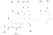
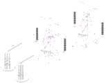
其中,1、7是试验线段,2、6是管母线,3、5、8、13、14、15是均压环,4是保护桶,9、16是室外光纤,10、12是承重绝缘子,11是光纤绝缘子,17、18是光纤转接盒,41是管母线,42、48是金属法兰,43、45是绝缘法兰,44是PE管,46是均压环,47是光纤接口,49是管母线开口,410是管母线开口顶盖,A1是高压发生器,A2是管母线,A3是高压塔杆,A4是架空导线,A5是承重绝缘子。Among them, 1, 7 are test line segments, 2, 6 are pipe bus bars, 3, 5, 8, 13, 14, 15 are pressure equalizing rings, 4 is a protection barrel, 9, 16 are outdoor optical fibers, 10, 12 are load-bearing insulators , 11 is an optical fiber insulator, 17, 18 is an optical fiber transfer box, 41 is a pipe bus, 42, 48 is a metal flange, 43, 45 is an insulating flange, 44 is a PE pipe, 46 is a pressure equalizing ring, and 47 is an optical fiber Interface, 49 is the opening of the tube busbar, 410 is the top cover of the tube busbar opening, A1 is the high voltage generator, A2 is the tube busbar, A3 is the high voltage tower pole, A4 is the overhead conductor, and A5 is the load-bearing insulator.
具体实施方式Detailed ways
现在参考附图介绍本发明的示例性实施方式,然而,本发明可以用许多不同的形式来实施,并且不局限于此处描述的实施例,提供这些实施例是为了详尽地且完全地公开本发明,并且向所属技术领域的技术人员充分传达本发明的范围。对于表示在附图中的示例性实施方式中的术语并不是对本发明的限定。在附图中,相同的单元/元件使用相同的附图标记。Exemplary embodiments of the present invention will now be described with reference to the accompanying drawings, however, the present invention may be embodied in many different forms and is not limited to the embodiments described herein, which are provided for the purpose of this thorough and complete disclosure invention, and fully convey the scope of the invention to those skilled in the art. The terms used in the exemplary embodiments shown in the drawings are not intended to limit the invention. In the drawings, the same elements/elements are given the same reference numerals.
除非另有说明,此处使用的术语(包括科技术语)对所属技术领域的技术人员具有通常的理解含义。另外,可以理解的是,以通常使用的词典限定的术语,应当被理解为与其相关领域的语境具有一致的含义,而不应该被理解为理想化的或过于正式的意义。Unless otherwise defined, terms (including scientific and technical terms) used herein have the commonly understood meanings to those skilled in the art. In addition, it is to be understood that terms defined in commonly used dictionaries should be construed as having meanings consistent with the context in the related art, and should not be construed as idealized or overly formal meanings.
图1示出了根据本发明实施方式的电晕损耗测量系统100的结构示意图。如图1所示,电晕损耗测量系统100包括:高压线上电压测量模块101、电阻传感器102、高压线上数据采集模块103、高压线下光电转换模块104、上位机105和供电模块106。高压线上电压测量模块101将测量得到的高压电压信号利用光纤传输线路实时传输至高压线上数据采集模块103。优选地,其中所述高压线上电压测量模块101位于圆柱形的金属材料的保护桶内,并且在所述保护桶的两端安装均压环。优选地,其中所述高压线上电压测量模块101安装在高压发生器的后端。优选地,其中所述高压线上 电压测量模块101包括:电压互感器、波形变换装置和光电转换发送器组;其中所述电压互感器的一次线圈串联接入高压交流线路,二次线圈接入波形变换装置和光电转换发送器,所述电压互感器将测量得到的高压电压电信号通过光电转换发送器转换为光信号并传输至高压线上数据采集模块103。FIG. 1 shows a schematic structural diagram of a corona
图2示出了根据本发明实施方式的电晕损耗测量系统中高压线上电压测量模块的流程图。如图2所示,高压线上电压测量模块101是将高压发生器产生的工频正弦交流高压电压信号转换为低压电压信号,并直接将模拟低电压信号转换为光信号后通过光缆传输线路实时传输至高压线上数据采集模块103。FIG. 2 shows a flowchart of a voltage measurement module on a high-voltage line in a corona loss measurement system according to an embodiment of the present invention. As shown in FIG. 2, the high-voltage online voltage measurement module 101 converts the power-frequency sinusoidal AC high-voltage voltage signal generated by the high-voltage generator into a low-voltage voltage signal, and directly converts the analog low-voltage signal into an optical signal, and transmits it in real time through the optical cable transmission line to the data acquisition module 103 on the high-voltage line.
图3示出了根据本发明实施方式的电晕损耗测量系统中电压信号波形传输的电路图的结构示意图。如图3所示,所述高压线上电压测量模块101到高压线上数据采集模块103的高压电压信号波形传输电路由HFBR1414光电发射模块、光缆、HFBR2416光电接收器以及调理电路组成。具体原理为:利用恒流源电路驱动所述光纤发射器HFBR1414将输入正弦波电压信号转换为光信号,通过光纤线缆传输至所述HFBR2416光电接收器,所述HFBR2416光电接收器将光信号转换为电信号后从2管脚输出,由于长距离传输信号会存在衰减、偏置等失真,对2管脚输出的信号进行调理。FIG. 3 shows a schematic structural diagram of a circuit diagram of a voltage signal waveform transmission in a corona loss measurement system according to an embodiment of the present invention. As shown in FIG. 3 , the high-voltage voltage signal waveform transmission circuit from the high-voltage online voltage measurement module 101 to the high-voltage online data acquisition module 103 is composed of HFBR1414 photoelectric transmitter module, optical cable, HFBR2416 photoelectric receiver and conditioning circuit. The specific principle is: use the constant current source circuit to drive the optical fiber transmitter HFBR1414 to convert the input sine wave voltage signal into an optical signal, and transmit it to the HFBR2416 photoelectric receiver through an optical fiber cable, and the HFBR2416 photoelectric receiver converts the optical signal into an optical signal. After the electrical signal is output from the 2-pin, the long-distance transmission signal will have distortions such as attenuation and offset, so the signal output from the 2-pin is conditioned.
优选地,电阻传感器102串联接入高压交流输电线路中,对电晕电流信号进行测量并传输至高压线上数据采集模块103。优选地,其中所述电阻传感器102与高压线上数据采集模块103设置在高压线上同一个位置处,并且所述电阻传感器与高压线上数据采集模块均安装在保护桶内,来减小高压交流线路产生的复杂电磁环境对电晕电流信号的影响。图4示出了根据本发明实施方式的电晕损耗测量系统中保护桶安装于试验线段的结构示意图。如图4所示,所述保护桶4被悬挂在两段管母线2和6之间,通过均压环3和5进行连接。承重绝缘子10和12悬挂起管母线2、6和试验线 段1、7,光纤从光纤绝缘子11内部穿过,并通过两端转接盒17、18与室外光纤16、9连接,室外光纤9的另一端接保护桶4的室外光纤接口47,室外光纤16的另一端接高压线下光电转换模块104和高压线上电压测量模块101。所述保护桶中的高压线上数据采集模块103采集得到信号后,通过室外光纤9传输至光纤绝缘子11,通过光纤绝缘子11传输至室外光纤16,室外光纤16是两段长距离室外光缆,一段用来连接高压线上电压测量模块101和高压线上数据采集模块103,将高压线上电压测量模块101测量得到的电压波形实时传输至高压线上数据采集模块103,另一段连接高压线下光电转换模块104,将高压线上数据采集模块103采集得到的信号传输至上位机105。Preferably, the resistance sensor 102 is connected in series to the high-voltage AC transmission line to measure the corona current signal and transmit it to the data acquisition module 103 on the high-voltage line. Preferably, the resistance sensor 102 and the data acquisition module 103 on the high-voltage line are arranged at the same position on the high-voltage line, and both the resistance sensor and the data acquisition module on the high-voltage line are installed in the protection barrel to reduce the generation of high-voltage AC lines. The influence of complex electromagnetic environment on corona current signal. FIG. 4 shows a schematic structural diagram of a protective barrel installed on a test line segment in a corona loss measurement system according to an embodiment of the present invention. As shown in FIG. 4 , the
图5示出了根据本发明实施方式的电晕损耗测量系统中保护桶放置高压线上数据采集模块与电阻传感器示意图。如图5所示,所述高压线上数据采集模块103通过管母线开口49安装在管母线41内,并通过4个内六角螺母固定住410管母线开口顶盖,通过管母线对高压线上数据采集模块进行电磁屏蔽,保障采集得到的信号不受外部强电磁干扰影响,并且保证在复杂气象条件下设备的安全可靠。所述电阻传感器102放置于PE管44中,高压线上数据采集模块103通过屏蔽双绞线分别连接电阻传感器102的两端,当电阻中有电流时,高压线上数据采集模块103可以采集得到电阻传感器102两端的电压数据。FIG. 5 shows a schematic diagram of a data acquisition module and a resistance sensor placed on a high-voltage line in a protection barrel in a corona loss measurement system according to an embodiment of the present invention. As shown in FIG. 5 , the high-voltage online data acquisition module 103 is installed in the
优选地,高压线上数据采集模块103采用双通道同步采集模式对所述高压电压信号和所述电晕电流信号进行同步采集,并分别转换为两个光信号后利用光纤传输线路传送至高压线下光电转换模块104。优选地,其中所述高压线上数据采集模块103包括:采集卡,光电转换器和控制电路板;其中所述控制电路板是高压线上数据采集模块103设备连接的枢纽,对高压线上数据采集模块103设备的状态进行控制,所述光电转换器将通过光纤传输线路传输给高压线上数据采集模块103的光信号转换为电信号并传输至采集卡。Preferably, the high-voltage online data acquisition module 103 adopts a dual-channel synchronous acquisition mode to synchronously collect the high-voltage voltage signal and the corona current signal, and convert them into two optical signals respectively, and then transmit them to the high-voltage offline optoelectronics through an optical fiber transmission line. Conversion module 104 . Preferably, the high-voltage online data acquisition module 103 includes: an acquisition card, a photoelectric converter and a control circuit board; wherein the control circuit board is a hub for the equipment connection of the high-voltage online data acquisition module 103, and the high-voltage online data acquisition module 103 The state of the device is controlled, and the photoelectric converter converts the optical signal transmitted to the data acquisition module 103 on the high-voltage line through the optical fiber transmission line into an electrical signal and transmits it to the acquisition card.
图6示出了根据本发明实施方式的电晕损耗测量系统中采用的 采集装置的结构示意图。如图6所示,采集装置同步采集法是将高压电压波形信号和电晕电流信号传输至同一空间方位,再利用采集装置的多通道同步采集技术进行信号同步采集。优选地,其中所述采集卡将采集到的两个电信号分别通过光电转换转换为两个光信号后,通过光纤传输线路下传到高压线下光电转换模块104。优选地,其中所述高压线上数据采集模块103通过所述光纤传输线路与所述高压线下光电转换模块104相连接。Fig. 6 shows a schematic structural diagram of a collection device used in a corona loss measurement system according to an embodiment of the present invention. As shown in Figure 6, the synchronous acquisition method of the acquisition device is to transmit the high-voltage voltage waveform signal and the corona current signal to the same spatial orientation, and then use the multi-channel synchronous acquisition technology of the acquisition device to synchronously acquire the signals. Preferably, the acquisition card converts the two collected electrical signals into two optical signals through photoelectric conversion, and then downlinks them to the photoelectric conversion module 104 under the high-voltage line through an optical fiber transmission line. Preferably, the high-voltage online data acquisition module 103 is connected to the high-voltage offline photoelectric conversion module 104 through the optical fiber transmission line.
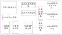
图7示出了根据本发明实施方式的电晕损耗测量系统中控制电路板逻辑示意图。如图7所示,所述控制电路板作为高压线上数据采集模块103的控制核心部分,是高压线上数据采集模块103设备连接的枢纽,通过控制电路板,可以实现对高压线上数据采集模块103设备状态的控制。FIG. 7 shows a schematic diagram of a control circuit board in a corona loss measurement system according to an embodiment of the present invention. As shown in FIG. 7 , the control circuit board, as the control core part of the high-voltage online data acquisition module 103, is the hub for the connection of the high-voltage online data acquisition module 103 equipment. state control.
所述控制电路板主要完成六项工作:1)设备供电:在高压线上数据采集模块103中,各种设备的工作电压都不相同,其中,采集卡工作电压为+6V,USB—光纤转换器工作电压为+5V,电压波形接收装置的工作电压为+5V,-5V,使用电源芯片来进行电压转换,系统供电采用12V电池供电,一块5V供电芯片LM2576-5一直运行以提供5V电源,LM2678ADJ和LM2678-5分别进行通断来控制采集卡以及USB—光纤转换器的供电,选用LM2660芯片提供-5V电源,同时通过对PCB电路板进行一定程度上的电磁屏蔽设计,以及外围的电磁防护措施,减小强电磁环境对设备供电的影响,保证了系统的稳定运行;2)电压波形接收调理:在控制电路板上集成有光纤接收器及相关电路,可以将高压线上电压测量模块101传输来的电压波形光信号转化为电信号,调整波形后,传输至采集卡进行采集;3)光纤开关:在控制板上同时集成有光纤遥控开关的接收器,光纤开关的发射器位于高压线下光电转换模块内,通过上位机控制光线开关发射模块,可以远程控制设备的供电,从而控制整个采集系统的工作状态;4)信号测量切换:控制电路板上设计有一个光纤开关测量切换装置,这是由于本次使用的采集卡只有2路信号输入,而整个系统需要测量的量有三个:电晕电流、电压波形和电池电压,因此,通过一个磁保持继电器完成信号的切换测量;5)设备过压保护:由于工作环境电压等级在百万伏左右,瞬间高 压脉冲容易破坏传感元件和采集卡通道,为防止此类情况发生,可在电阻两端加上保护电路,并联P6KE15CA瞬态抑制二极管TVS和2R-75V陶瓷放电二极管;6)设备短路保护:对于测量系统采集模块而言,其所受到的高压影响不仅限于高压线路本身,还可能来自于雷电天气环境下的雷电的袭击,因此,在雷电天气环境对采集卡所有探头都进行短路保护。具体措施是使用继电器的COM端和RESET端分别连接采集卡探头的+级和-级,在使用采集卡时,通过光纤开关控制继电器COM端和SET端断开,采集卡进行正常的测量工作;当不进行测量时,光纤开关控制继电器闭合将采集卡探头短路,这样,加上TVS管和气体放电管,可以达到保护采集卡的目的。The control circuit board mainly completes six tasks: 1) Equipment power supply: In the data acquisition module 103 on the high-voltage line, the working voltages of various equipment are different, wherein the working voltage of the acquisition card is +6V, and the USB-fiber converter The working voltage is +5V, the working voltage of the voltage waveform receiving device is +5V, -5V, the power chip is used for voltage conversion, the system power supply is powered by 12V battery, a 5V power supply chip LM2576-5 runs all the time to provide 5V power supply, LM2678ADJ On-off with LM2678-5 to control the power supply of the capture card and the USB-to-fiber converter, select the LM2660 chip to provide -5V power supply, and at the same time carry out a certain degree of electromagnetic shielding design for the PCB circuit board, as well as peripheral electromagnetic protection measures , reduce the influence of strong electromagnetic environment on the power supply of the equipment, and ensure the stable operation of the system; 2) Voltage waveform receiving and conditioning: The optical fiber receiver and related circuits are integrated on the control circuit board, which can transmit the voltage measurement module 101 on the high-voltage line to the 3) Optical fiber switch: the receiver of the optical fiber remote control switch is integrated on the control board at the same time, and the transmitter of the optical fiber switch is located under the high-voltage line photoelectric conversion In the module, through the host computer to control the optical switch launch module, the power supply of the equipment can be remotely controlled, thereby controlling the working state of the entire acquisition system; 4) Signal measurement switching: There is an optical switch measurement switching device on the control circuit board. This is because The acquisition card used this time has only 2 signal inputs, and the entire system needs to measure three quantities: corona current, voltage waveform and battery voltage. Therefore, the signal switching measurement is completed through a magnetic latching relay; 5) Equipment overvoltage Protection: Since the voltage level of the working environment is around one million volts, instantaneous high-voltage pulses can easily damage the sensing element and the acquisition card channel. To prevent this from happening, a protection circuit can be added at both ends of the resistor, and a P6KE15CA transient suppression diode TVS can be connected in parallel. and 2R-75V ceramic discharge diode; 6) Equipment short-circuit protection: For the acquisition module of the measurement system, the high-voltage impact on it is not limited to the high-voltage line itself, but may also come from the lightning attack in the lightning weather environment. All probes of the acquisition card are short-circuit protected in the lightning weather environment. The specific measures are to use the COM terminal and the RESET terminal of the relay to connect the + level and - level of the acquisition card probe respectively. When the acquisition card is used, the COM terminal and the SET terminal of the relay are controlled to be disconnected through the optical switch, and the acquisition card performs normal measurement work; When the measurement is not performed, the optical fiber switch control relay is closed to short-circuit the probe of the acquisition card. In this way, the TVS tube and the gas discharge tube can be added to protect the acquisition card.
优选地,高压线下光电转换模块104将所述两个光信号通过光电转换分别转换为两个电信号,并传输给上位机105进行处理。图8示出了根据本发明实施方式的电晕损耗测量系统中高压线下侧设备的连接示意图。如图8所示,所述高压线下光电转换模块104通过USB接口和串行接口与一台高性能计算机连接,两者被安置于距离试验线段存在一段距离的控制室内,控制人员通过实现编写好的采集程序和人机界面来操作这台高性能计算机发出电信号形式的控制命令,高压线下光电转换模块104将电信号转换为光信号,再通过室外光纤传输至测量系统高压线上侧,到达控制高压线上侧设备的目的。Preferably, the photoelectric conversion module 104 under the high-voltage line converts the two optical signals into two electrical signals respectively through photoelectric conversion, and transmits them to the upper computer 105 for processing. FIG. 8 shows a schematic diagram of the connection of the equipment on the lower side of the high-voltage line in the corona loss measurement system according to an embodiment of the present invention. As shown in FIG. 8 , the photoelectric conversion module 104 under the high-voltage line is connected to a high-performance computer through a USB interface and a serial interface, and the two are placed in a control room that is at a distance from the test line. The acquisition program and human-machine interface are used to operate the high-performance computer to issue control commands in the form of electrical signals. The photoelectric conversion module 104 under the high-voltage line converts the electrical signals into optical signals, and then transmits them to the high-voltage line of the measurement system through the outdoor optical fiber. The purpose of the equipment on the upper side of the high voltage line.
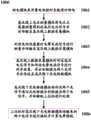
优选地,上位机105对高压线下光电转换模块104传输来的两个电信号进行接收并计算电晕损耗。图9示出了根据本发明实施方式的电晕损耗测量系统中上位机所执行的功能流程图。如图9所示,所述上位机105通过USB接口及串行接口与所述高压线下光电转换模块104相连接,首先打开连接端口,进入到手动采集界面,选择是则进入到测量系统界面,否则重新回到打开端口界面;当进入到测量系统界面后,打开线上模块电源,判断电量是否充足,如果充足则初始化采集卡,其中采集卡为双通道同步采集,之后设置存储路径以及电压电流等级,如果电量不足,则直接结束整个测量过程;设置存储路径以及电压电流等级完成之后判断是否自动采 集,如果选择是,则自动对数据进行采集、处理和保存;反之,则采用手动采集的模式,对数据进行采集、处理和保存;随后结束测量过程并关闭线上模块的电源,测量过程结束。在整个系统中,上位机接收、保存并处理所述高电压信号和电晕电流信号,进而得到所需电晕损耗。Preferably, the host computer 105 receives the two electrical signals transmitted from the photoelectric conversion module 104 under the high-voltage line and calculates the corona loss. FIG. 9 shows a flow chart of functions performed by the upper computer in the corona loss measurement system according to an embodiment of the present invention. As shown in FIG. 9 , the host computer 105 is connected to the photoelectric conversion module 104 under the high-voltage line through the USB interface and the serial interface. First, open the connection port and enter the manual acquisition interface. If yes, enter the measurement system interface. Otherwise, go back to the interface of opening the port; when entering the interface of the measurement system, turn on the power of the online module to determine whether the power is sufficient. If it is sufficient, initialize the acquisition card, in which the acquisition card is dual-channel synchronous acquisition, and then set the storage path and voltage and current. If the power is insufficient, the entire measurement process will be ended directly; after setting the storage path and voltage and current levels, it will be determined whether to automatically collect or not. If yes, the data will be collected, processed and saved automatically; otherwise, the manual collection mode will be used. , to collect, process and save the data; then end the measurement process and turn off the power of the online module, and the measurement process ends. In the whole system, the upper computer receives, saves and processes the high voltage signal and corona current signal, and then obtains the required corona loss.
优选地,供电模块106采用蓄电池组供电,保证所述系统可以正常工作。Preferably, the power supply module 106 is powered by a battery pack to ensure that the system can work normally.
图10示出了根据本发明实施方式的电晕损耗测量方法1000的流程图。如图10所示,电晕损耗测量方法从步骤1001开始,在步骤1001供电模块采用蓄电池组对系统进行供电,保证所述系统可以正常工作。FIG. 10 shows a flowchart of a
优选地,在步骤1002高压线上电压测量模块将电压互感器测量得到的高压电压信号利用光纤传输线路实时传输至高压线上数据采集模块。优选地,中所述高压线上电压测量模块安装在高压发生器的后端。优选地,其中所述高压线上电压测量模块位于圆柱形的金属材料的保护桶内,并且在所述保护桶的两端安装均压环。优选地,其中所述高压线上电压测量模块包括:电压互感器、波形变换装置和光电转换发送器组;其中所述电压互感器的一次线圈串联接入高压交流线路,二次线圈接入波形变换装置和光电转换发送器,所述电压互感器将测量得到的电压电信号通过光电转换发送器转换为光信号并传输至高压线上数据采集模块。Preferably, in
优选地,在步骤1003利用电阻传感器对电晕电流信号进行测量并传输至高压线上数据采集模块。优选地,其中所述电阻传感器串联接入高压交流输电线路中。Preferably, in
优选地,在步骤1004高压线上数据采集模块对所述高压电压信号和所述电晕电流信号进行同步采集,并分别转换为两个光信号后利用光纤传输线路传送至高压线下光电转换模块。优选地,其中所述高压线上数据采集模块采用双通道同步采集模式。优选地,其中所述电阻传感器与高压线上数据采集模块设置在高压线上同一个位置处,并且所述电阻传感器与高压线上数据采集模块均安装在保护桶内,来减小高压交流线路产生的复杂电磁环境对电晕电流信号的影响。优选地,其中所述高压线上数据采集模块 包括:采集卡,光电转换器和控制电路板;其中所述控制电路板是高压线上数据采集模块设备连接的枢纽,对高压线上数据采集模块设备的状态进行控制,所述光电转换器将通过光纤传输线路传输给高压线上数据采集模块的光信号转换为电信号并传输至采集卡。优选地,其中所述采集卡将采集到的两个电信号分别通过光电转换转换为两个光信号后,通过光纤传输线路下传到高压线下光电转换模块。Preferably, in
优选地,在步骤1005高压线下光电转换模块将所述两个光信号通过光电转换分别转换为两个电信号,并传输给上位机进行处理。优选地,其中所述高压线上数据采集模块通过所述光纤传输线路与所述高压线下光电转换模块相连接。Preferably, in
优选地,在步骤1006上位机对高压线下光电转换模块传输来的两个电信号进行接收并计算电晕损耗。Preferably, in
图11示出了根据本发明实施方式的霸州特高压杆塔试验基地的交流1000kV高压同塔双回路杆塔示意图。如图11所示,高压交流输电线路电晕损耗测量系统的应用平台是霸州特高压杆塔试验基地的交流1000千伏特高压同塔双回路杆塔。高压线上电压测量模块安装在高压发生器A1后面,高压线上数据采集模块和电阻传感器统一安装在保护桶内,并悬挂安装于承重绝缘子A5下面,用室外光纤通过光纤绝缘子将高压线上数据采集模块与高压线下光电装换模块和高压线上电压测量模块连接起来,并将高压线下光电装换模块和上位机连接起来。11 shows a schematic diagram of an AC 1000kV high-voltage double-circuit pole tower on the same tower in the Bazhou UHV pole tower test base according to an embodiment of the present invention. As shown in Figure 11, the application platform of the high-voltage AC transmission line corona loss measurement system is the
在进行特高压交流输电线路电晕损耗测量相关实验时,首先对导线段加上电压,控制人员在升压室控制高压发生器逐步按要求产生交流高电压,通过管母线传输至架空导线上,架空导线一端加特高压电压,另外一端悬空。在高压发生器对导线升压的过程中,导线以及作为电源的高压发生器无法形成电路回路,导致在架空导线上存在电压,但没有电流。当电压等级从100kV一直上升到1000kV时,空气被击穿,导线段对空气进行电晕放电,这样,就会形成电流通路,产生电晕损耗。When conducting experiments related to corona loss measurement of UHV AC transmission lines, voltage is first applied to the wire segment, and the controller controls the high-voltage generator in the booster room to gradually generate AC high voltage as required, and transmits it to the overhead wire through the tube bus. One end of the overhead wire is applied with extra-high voltage, and the other end is suspended. In the process of boosting the wire by the high-voltage generator, the wire and the high-voltage generator as a power source cannot form a circuit loop, resulting in a voltage but no current on the overhead wire. When the voltage level rises from 100kV to 1000kV, the air is broken down, and the wire segment corona discharges the air, so that a current path will be formed and corona loss will be generated.
已经通过参考少量实施方式描述了本发明。然而,本领域技术人员所 公知的,正如附带的专利权利要求所限定的,除了本发明以上公开的其他的实施例等同地落在本发明的范围内。The present invention has been described with reference to a few embodiments. However, as is known to those skilled in the art, other embodiments of the invention than those disclosed above are equally within the scope of the invention, as defined by the appended patent claims.
通常地,在权利要求中使用的所有术语都根据他们在技术领域的通常含义被解释,除非在其中被另外明确地定义。所有的参考“一个/所述/该[装置、组件等]”都被开放地解释为所述装置、组件等中的至少一个实例,除非另外明确地说明。这里公开的任何方法的步骤都没必要以公开的准确的顺序运行,除非明确地说明。Generally, all terms used in the claims are to be interpreted according to their ordinary meaning in the technical field, unless explicitly defined otherwise herein. All references to "a/the/the [means, component, etc.]" are open to interpretation as at least one instance of said means, component, etc., unless expressly stated otherwise. The steps of any method disclosed herein do not have to be performed in the exact order disclosed, unless explicitly stated.
Claims (15)
Translated fromChinesePriority Applications (1)
| Application Number | Priority Date | Filing Date | Title |
|---|---|---|---|
| CN201610600187.8ACN106226603B (en) | 2016-07-26 | 2016-07-26 | Corona loss measurement system and method for high-voltage alternating-current transmission line |
Applications Claiming Priority (1)
| Application Number | Priority Date | Filing Date | Title |
|---|---|---|---|
| CN201610600187.8ACN106226603B (en) | 2016-07-26 | 2016-07-26 | Corona loss measurement system and method for high-voltage alternating-current transmission line |
Publications (2)
| Publication Number | Publication Date |
|---|---|
| CN106226603A CN106226603A (en) | 2016-12-14 |
| CN106226603Btrue CN106226603B (en) | 2020-10-20 |
Family
ID=57533061
Family Applications (1)
| Application Number | Title | Priority Date | Filing Date |
|---|---|---|---|
| CN201610600187.8AActiveCN106226603B (en) | 2016-07-26 | 2016-07-26 | Corona loss measurement system and method for high-voltage alternating-current transmission line |
Country Status (1)
| Country | Link |
|---|---|
| CN (1) | CN106226603B (en) |
Families Citing this family (8)
| Publication number | Priority date | Publication date | Assignee | Title |
|---|---|---|---|---|
| US10571509B2 (en) | 2017-10-17 | 2020-02-25 | Facebook, Inc. | Systems and methods for distributed sensing of a powerline conductor |
| CN108646076A (en)* | 2018-04-27 | 2018-10-12 | 国家电网公司 | Double resistance multi-channel type high voltage direct current photoelectricity flow measuring systems and method |
| CN108872676B (en)* | 2018-06-04 | 2019-08-27 | 华北电力大学 | A measuring device for power frequency voltage of substation busbar |
| CN109166754B (en)* | 2018-10-20 | 2019-12-17 | 华北电力大学 | A high-voltage circuit breaker and a power measurement system including the high-voltage circuit breaker |
| ES2969870T3 (en)* | 2019-01-09 | 2024-05-23 | Microelettrica Scientifica Spa | Improved device for measuring the electrical power consumed by a railway vehicle from a high voltage electrical supply line |
| CN111239556B (en)* | 2020-02-03 | 2022-12-06 | 华北电力大学 | Experimental device for detecting corona starting voltage of alternating current-direct current system and measuring method thereof |
| CN114690030B (en)* | 2020-12-29 | 2025-09-09 | 北京科益虹源光电技术有限公司 | High-voltage switching tube driving signal testing device and method |
| US11774695B2 (en) | 2021-01-22 | 2023-10-03 | Macleon, LLC | Optical fiber cable |
Citations (2)
| Publication number | Priority date | Publication date | Assignee | Title |
|---|---|---|---|---|
| SU1114958A1 (en)* | 1981-09-15 | 1984-09-23 | Киевский Отдел Комплексного Проектирования Украинского Отделения Ордена Октябрьской Революции Всесоюзного Государственного Проектно-Изыскательского И Научно-Исследовательского Института "Энергосетьпроект" | Method of measuring losses of electric energy for corona discharge in loaded high=voltage electric power line |
| SU1684706A2 (en)* | 1988-12-30 | 1991-10-15 | Азербайджанский Научно-Исследовательский Институт Энергетики Им.И.Г.Есьмана | Method of measuring total power losses in high-voltage power transmission line |
Family Cites Families (3)
| Publication number | Priority date | Publication date | Assignee | Title |
|---|---|---|---|---|
| CN102818928A (en)* | 2011-12-16 | 2012-12-12 | 清华大学 | Current probe-based on-line measuring system for high-frequency corona pulse current on high-voltage line |
| CN204462246U (en)* | 2015-03-27 | 2015-07-08 | 国家电网公司 | A kind of HVDC (High Voltage Direct Current) transmission line corona loss measuring system |
| CN205958653U (en)* | 2016-07-26 | 2017-02-15 | 中国电力科学研究院 | High voltage transmission line's corona loss measuring equipment |
- 2016
- 2016-07-26CNCN201610600187.8Apatent/CN106226603B/enactiveActive
Patent Citations (2)
| Publication number | Priority date | Publication date | Assignee | Title |
|---|---|---|---|---|
| SU1114958A1 (en)* | 1981-09-15 | 1984-09-23 | Киевский Отдел Комплексного Проектирования Украинского Отделения Ордена Октябрьской Революции Всесоюзного Государственного Проектно-Изыскательского И Научно-Исследовательского Института "Энергосетьпроект" | Method of measuring losses of electric energy for corona discharge in loaded high=voltage electric power line |
| SU1684706A2 (en)* | 1988-12-30 | 1991-10-15 | Азербайджанский Научно-Исследовательский Институт Энергетики Им.И.Г.Есьмана | Method of measuring total power losses in high-voltage power transmission line |
Non-Patent Citations (2)
| Title |
|---|
| 1000kv特高压交流输电线路双回耐张塔刚性跳线电晕抑制分析;杨熙等;《高电压技术》;20140630;第40卷(第6期);第1539-1546页* |
| 应用电晕笼的特高压交流输电线路;裴春明等;《电网技术》;20160530;第40卷(第5期);第1583-1588页* |
Also Published As
| Publication number | Publication date |
|---|---|
| CN106226603A (en) | 2016-12-14 |
Similar Documents
| Publication | Publication Date | Title |
|---|---|---|
| CN106226603B (en) | Corona loss measurement system and method for high-voltage alternating-current transmission line | |
| US20150362536A1 (en) | High-voltage direct current broad frequency-domain corona current measurement system | |
| CN105116296B (en) | The special fault detector of grid cable run | |
| CN104360227B (en) | Substation cable outlet fault monitoring method based on traveling wave method and transient basic frequency method | |
| CN106645865B (en) | Device for measuring corona current of high-voltage transmission line | |
| WO2014173317A1 (en) | Power transmission line lightning electromagnetic transient dynamic simulation experimental system | |
| Harid et al. | A wireless system for monitoring leakage current in electrical substation equipment | |
| CN104124916B (en) | High aititude photovoltaic plant electric network fault simulated testing system mobile detection apparatus | |
| CN115453223A (en) | Be used for novel photovoltaic inverter to wade net operational performance engineering test system | |
| CN203405509U (en) | A high-voltage cable instantaneous short circuit fault current detecting apparatus designed by a Rogowski Coil | |
| CN205958653U (en) | High voltage transmission line's corona loss measuring equipment | |
| CN109470914A (en) | A VFTO signal measuring device | |
| CN104600650B (en) | Test method for direct current melting ice of wire and ground wire combination based on fully insulated ground wire technology | |
| CN204089727U (en) | High-altitude photovoltaic power station grid fault simulation test system mobile detection equipment | |
| CN205027858U (en) | Special fault indicator of high -tension transmission net cable run | |
| CN204989339U (en) | Monitoring device for high -voltage electric transmission line | |
| CN104360193B (en) | Electromagnetic disturbance simulation test platform of transformer substation secondary system | |
| CN202975211U (en) | Photoelectric trigger device for transient disturbance test of transformer substation | |
| CN104501976A (en) | Passive wireless temperature acquisition system | |
| Huang et al. | An on-line monitoring system of transmission line conductor de-icing | |
| CN211577308U (en) | Detection system of external signal generation device | |
| CN204359460U (en) | A kind of Optical Fiber composite overhead Ground Wire DC ice melting temperature strain monitoring device | |
| CN203376430U (en) | Substation secondary control cable shielding current real-time monitoring device | |
| CN205355535U (en) | Box type transformer station | |
| CN206057412U (en) | A kind of device corona current of high-voltage transmission line measured by corona cage |
Legal Events
| Date | Code | Title | Description |
|---|---|---|---|
| C06 | Publication | ||
| PB01 | Publication | ||
| SE01 | Entry into force of request for substantive examination | ||
| SE01 | Entry into force of request for substantive examination | ||
| GR01 | Patent grant | ||
| GR01 | Patent grant |