CN106200308B - Image forming apparatus and detachable unit - Google Patents
Image forming apparatus and detachable unitDownload PDFInfo
- Publication number
- CN106200308B CN106200308BCN201510425757.XACN201510425757ACN106200308BCN 106200308 BCN106200308 BCN 106200308BCN 201510425757 ACN201510425757 ACN 201510425757ACN 106200308 BCN106200308 BCN 106200308B
- Authority
- CN
- China
- Prior art keywords
- detachable unit
- circuit board
- image forming
- forming apparatus
- insertion direction
- Prior art date
- Legal status (The legal status is an assumption and is not a legal conclusion. Google has not performed a legal analysis and makes no representation as to the accuracy of the status listed.)
- Active
Links
- 238000003780insertionMethods0.000claimsabstractdescription62
- 230000037431insertionEffects0.000claimsabstractdescription62
- 238000000605extractionMethods0.000claimsabstractdescription16
- 239000000758substrateSubstances0.000claimsdescription7
- 238000005452bendingMethods0.000claimsdescription2
- 230000004048modificationEffects0.000description9
- 238000012986modificationMethods0.000description9
- 239000004065semiconductorSubstances0.000description5
- 238000000034methodMethods0.000description4
- 238000004140cleaningMethods0.000description3
- 239000003086colorantSubstances0.000description3
- 230000000052comparative effectEffects0.000description3
- 238000010586diagramMethods0.000description3
- 208000033999Device damageDiseases0.000description1
- 230000005540biological transmissionEffects0.000description1
- 238000002788crimpingMethods0.000description1
- PCHJSUWPFVWCPO-UHFFFAOYSA-NgoldChemical compound[Au]PCHJSUWPFVWCPO-UHFFFAOYSA-N0.000description1
- 239000010931goldSubstances0.000description1
- 229910052737goldInorganic materials0.000description1
- 230000003287optical effectEffects0.000description1
- 230000002093peripheral effectEffects0.000description1
Images


Classifications
- G—PHYSICS
- G03—PHOTOGRAPHY; CINEMATOGRAPHY; ANALOGOUS TECHNIQUES USING WAVES OTHER THAN OPTICAL WAVES; ELECTROGRAPHY; HOLOGRAPHY
- G03G—ELECTROGRAPHY; ELECTROPHOTOGRAPHY; MAGNETOGRAPHY
- G03G21/00—Arrangements not provided for by groups G03G13/00 - G03G19/00, e.g. cleaning, elimination of residual charge
- G03G21/16—Mechanical means for facilitating the maintenance of the apparatus, e.g. modular arrangements
- G03G21/18—Mechanical means for facilitating the maintenance of the apparatus, e.g. modular arrangements using a processing cartridge, whereby the process cartridge comprises at least two image processing means in a single unit
- G03G21/1839—Means for handling the process cartridge in the apparatus body
- G03G21/1867—Means for handling the process cartridge in the apparatus body for electrically connecting the process cartridge to the apparatus, electrical connectors, power supply
- G—PHYSICS
- G03—PHOTOGRAPHY; CINEMATOGRAPHY; ANALOGOUS TECHNIQUES USING WAVES OTHER THAN OPTICAL WAVES; ELECTROGRAPHY; HOLOGRAPHY
- G03G—ELECTROGRAPHY; ELECTROPHOTOGRAPHY; MAGNETOGRAPHY
- G03G15/00—Apparatus for electrographic processes using a charge pattern
- G03G15/06—Apparatus for electrographic processes using a charge pattern for developing
- G03G15/08—Apparatus for electrographic processes using a charge pattern for developing using a solid developer, e.g. powder developer
- G03G15/0822—Arrangements for preparing, mixing, supplying or dispensing developer
- G03G15/0863—Arrangements for preparing, mixing, supplying or dispensing developer provided with identifying means or means for storing process- or use parameters, e.g. an electronic memory
- G—PHYSICS
- G03—PHOTOGRAPHY; CINEMATOGRAPHY; ANALOGOUS TECHNIQUES USING WAVES OTHER THAN OPTICAL WAVES; ELECTROGRAPHY; HOLOGRAPHY
- G03G—ELECTROGRAPHY; ELECTROPHOTOGRAPHY; MAGNETOGRAPHY
- G03G21/00—Arrangements not provided for by groups G03G13/00 - G03G19/00, e.g. cleaning, elimination of residual charge
- G03G21/16—Mechanical means for facilitating the maintenance of the apparatus, e.g. modular arrangements
- G03G21/18—Mechanical means for facilitating the maintenance of the apparatus, e.g. modular arrangements using a processing cartridge, whereby the process cartridge comprises at least two image processing means in a single unit
- G03G21/1875—Mechanical means for facilitating the maintenance of the apparatus, e.g. modular arrangements using a processing cartridge, whereby the process cartridge comprises at least two image processing means in a single unit provided with identifying means or means for storing process- or use parameters, e.g. lifetime of the cartridge
- G03G21/1878—Electronically readable memory
- G03G21/1882—Electronically readable memory details of the communication with memory, e.g. wireless communication, protocols
- G03G21/1885—Electronically readable memory details of the communication with memory, e.g. wireless communication, protocols position of the memory; memory housings; electrodes
Landscapes
- Engineering & Computer Science (AREA)
- Physics & Mathematics (AREA)
- General Physics & Mathematics (AREA)
- Computer Vision & Pattern Recognition (AREA)
- Computer Networks & Wireless Communication (AREA)
- Electrophotography Configuration And Component (AREA)
Abstract
Translated fromChinese
Description
Translated fromChinese技术领域technical field
本发明涉及每一个均包括可拆卸单元的图像形成装置以及可以附接到图像形成装置和从图像形成装置拆卸的可拆卸单元。The present invention relates to image forming apparatuses each including a detachable unit and a detachable unit attachable to and detachable from the image forming apparatus.
背景技术Background technique
通常,图像形成装置具有可拆卸单元,当所述可拆卸单元被插入到装置主体中或者从装置主体取出时可以沿着装置主体的引导部滑动。可拆卸单元的一个示例是调色剂盒。一般,可拆卸单元包括用于保持电路板(盒(cartridge)电路板)的支架,并且具有作为弹簧片的接触端子的端子板被安装在装置主体上。当可拆卸单元被插入到装置主体的引导部中时,在可拆卸单元的支架中保持的电路板的电极端子开始与接触端子接触。电路板包括存储关于保持该电路板的可拆卸单元的信息的半导体元件以及具有平的接触面的电极端子。Generally, an image forming apparatus has a detachable unit that can slide along a guide portion of the apparatus main body when inserted into or taken out from the apparatus main body. An example of a detachable unit is a toner cartridge. Generally, the detachable unit includes a bracket for holding a circuit board (cartridge circuit board), and a terminal board having contact terminals as spring pieces is mounted on the apparatus main body. When the detachable unit is inserted into the guide portion of the apparatus main body, the electrode terminals of the circuit board held in the holder of the detachable unit come into contact with the contact terminals. The circuit board includes semiconductor elements storing information about the detachable unit holding the circuit board and electrode terminals with flat contact surfaces.
当用户将在支架中保持电路板的可拆卸单元沿着引导部插入到装置主体中时,处于其初始状态(非压接状态)的接触端子触及可拆卸单元的支架的前端侧上的部分,并被下推。当插入完成时,保持在支架中的接触端子处于压接(press)状态并且通过其弹性恢复力维持处于与电路板的电极端子接触。图像形成装置的控制部通过电路板的电极端子、端子板的接触端子以及连接到接触端子的信号线缆来获取存储在电路板的半导体元件中的信息。When the user inserts the detachable unit holding the circuit board in the holder into the apparatus main body along the guide portion, the contact terminal in its initial state (non-crimped state) touches the portion on the front end side of the holder of the detachable unit, and pushed down. When the insertion is completed, the contact terminal held in the holder is in a pressed state and maintained in contact with the electrode terminal of the circuit board by its elastic restoring force. The control section of the image forming apparatus acquires the information stored in the semiconductor elements of the circuit board through the electrode terminals of the circuit board, the contact terminals of the terminal board, and the signal cables connected to the contact terminals.
当用户通过沿着引导部滑动可拆卸单元来从装置主体抽出在支架中保持电路板的可拆卸单元时,保持在支架中的可拆卸单元移动而使电路板的电极端子维持处于与接触端子接触。当可拆卸单元移动远离接触端子时,接触端子通过其弹性恢复力从压接状态返回到初始状态。参见专利文献1,日本专利申请公开号2007-140266。When the user draws out the detachable unit holding the circuit board in the holder from the apparatus main body by sliding the detachable unit along the guide, the detachable unit held in the holder moves to maintain the electrode terminals of the circuit board in contact with the contact terminals . When the detachable unit moves away from the contact terminal, the contact terminal returns from the crimped state to the initial state by its elastic restoring force. See Patent Document 1, Japanese Patent Application Laid-Open No. 2007-140266.
存在如下可能性,将未在支架中保持电路板的可拆卸单元(例如,安装电路板之前的可拆卸单元或已经移除了电路板之后的可拆卸单元)沿着引导部插入到装置主体中。当用户将在支架中未保持电路板的可拆卸单元沿着引导部插入到装置主体中时,处于其初始状态的接触端子触及可拆卸单元的支架的前端(tip end)(前部端)侧上的部分(电路板的定位部分),并暂时进入压接状态。然而,当插入完成时,接触端子通过其弹性恢复力返回到其初始状态并进入到可拆卸单元的支架(电路板将存在的空间)中。如果用户通过沿着引导部滑动可拆卸单元来拉出处于该状态下的可拆卸单元,已经进入可拆卸单元的支架中的接触端子将被可拆卸单元的支架的前端部分捕获并且将因此受损。There is a possibility that a detachable unit that does not hold the circuit board in the holder (for example, a detachable unit before the circuit board is installed or a detachable unit after the circuit board has been removed) is inserted into the apparatus main body along the guide portion . When the user inserts the detachable unit that does not hold the circuit board in the holder into the apparatus main body along the guide portion, the contact terminal in its initial state touches the tip end (front end) side of the holder of the detachable unit the upper part (the positioning part of the circuit board), and temporarily enter the crimping state. However, when the insertion is complete, the contact terminal returns to its original state by its elastic restoring force and enters the holder of the detachable unit (the space where the circuit board will exist). If the user pulls out the detachable unit in this state by sliding the detachable unit along the guide, the contact terminals that have entered into the bracket of the detachable unit will be caught by the front end portion of the bracket of the detachable unit and will be damaged accordingly .
发明内容SUMMARY OF THE INVENTION
本发明的一个目的是提供即使当用户沿着装置主体的引导部拉出在支架中未保持电路板的可拆卸单元时也不会损坏安装在装置主体上的接触端子的图像形成装置和可拆卸单元。An object of the present invention is to provide an image forming apparatus and a detachable unit that does not damage contact terminals mounted on the apparatus body even when a user pulls out a detachable unit that does not hold a circuit board in a holder along a guide portion of the apparatus body unit.
根据本发明的一个方面的图像形成装置包括:装置主体,包括引导部和作为弹簧的接触端子;以及可拆卸单元,包括用于保持具有开始与接触端子接触的电极端子的电路板的支架。可拆卸单元的状态通过在插入方向上沿着引导部插入可拆卸单元而变为附接状态,并且可拆卸单元的状态通过在与插入方向相反的取出方向上沿着引导部取出可拆卸单元而变为拆卸状态。支架包括用于当将在支架中保持电路板的可拆卸单元沿着引导部滑动以在插入方向上插入时定位电路板在插入方向上的前端的第一定位构件。第一定位构件包括凹口,所述凹口被配置成使得当在取出方向上滑动处于附接状态的未在支架中保持电路板的可拆卸单元时接触端子通过所述凹口。An image forming apparatus according to an aspect of the present invention includes: an apparatus main body including a guide portion and a contact terminal as a spring; and a detachable unit including a holder for holding a circuit board having an electrode terminal coming into contact with the contact terminal. The state of the detachable unit is changed to the attached state by inserting the detachable unit along the guide in the insertion direction, and the state of the detachable unit is changed by taking out the detachable unit along the guide in the extraction direction opposite to the insertion direction becomes disassembled. The bracket includes a first positioning member for positioning a front end of the circuit board in the insertion direction when the detachable unit holding the circuit board in the bracket is slid along the guide to be inserted in the insertion direction. The first positioning member includes a notch configured so that the contact terminal passes through the notch when the detachable unit in the attached state is slid in the extraction direction without holding the circuit board in the holder.
根据本发明的另一方面的可拆卸单元被配置成插入到图像形成装置中和从图像形成装置取出,所述图像形成装置包括引导部和作为弹簧的接触端子。可拆卸单元的状态通过在插入方向上沿着引导部插入可拆卸单元而变为附接状态,并且可拆卸单元的状态通过在与插入方向相反的取出方向上沿着引导部取出可拆卸单元而变为拆卸状态。可拆卸单元包括:单元主体;以及被提供在所述单元主体上的支架,所述支架被配置成保持包括开始与接触端子接触的电极端子的电路板。所述支架包括用于当将在支架中保持电路板的可拆卸单元沿着引导部滑动以在插入方向上插入时定位电路板在插入方向上的前端的第一定位构件。第一定位构件包括凹口,所述凹口被配置成使得当在取出方向上滑动处于附接状态的未在支架中保持电路板的可拆卸单元时接触端子通过所述凹口。A detachable unit according to another aspect of the present invention is configured to be inserted into and taken out from an image forming apparatus including a guide portion and a contact terminal as a spring. The state of the detachable unit is changed to the attached state by inserting the detachable unit along the guide in the insertion direction, and the state of the detachable unit is changed by taking out the detachable unit along the guide in the extraction direction opposite to the insertion direction becomes disassembled. The detachable unit includes: a unit main body; and a holder provided on the unit main body, the holder being configured to hold a circuit board including an electrode terminal coming into contact with the contact terminal. The bracket includes a first positioning member for positioning a front end of the circuit board in the insertion direction when the detachable unit holding the circuit board in the bracket is slid along the guide to be inserted in the insertion direction. The first positioning member includes a notch configured so that the contact terminal passes through the notch when the detachable unit in the attached state is slid in the extraction direction without holding the circuit board in the holder.
根据本发明,即使用户沿着引导部将未在支架中保持电路板的可拆卸单元滑动到装置主体中并且此后沿着引导部拉出它,安装在装置主体上的接触端子也不会被损坏。According to the present invention, even if the user slides the detachable unit that does not hold the circuit board in the holder into the device body along the guide portion and then pulls it out along the guide portion, the contact terminals mounted on the device body are not damaged .
附图说明Description of drawings
在附图中:In the attached image:
图1是示意性地示出本发明的第一实施例中的图像形成装置的结构的纵剖视图;1 is a longitudinal cross-sectional view schematically showing the structure of an image forming apparatus in a first embodiment of the present invention;
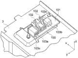
图2A是示意性地示出如何将作为第一实施例中的可拆卸单元的调色剂盒插入到布置在图像形成装置的装置主体中的引导部中的透视图;2A is a perspective view schematically showing how a toner cartridge, which is a detachable unit in the first embodiment, is inserted into a guide portion arranged in the apparatus main body of the image forming apparatus;
图2B是示意性地示出如何将作为第一实施例中的可拆卸单元的调色剂盒插入到布置在装置主体中的引导部中的纵剖视图;2B is a longitudinal sectional view schematically showing how the toner cartridge, which is the detachable unit in the first embodiment, is inserted into a guide portion arranged in the apparatus main body;
图3是示出第一实施例中的调色剂盒的支架的透视图;FIG. 3 is a perspective view showing the holder of the toner cartridge in the first embodiment;
图4是示出第一实施例中的调色剂盒的支架、电路板、以及固定构件的透视图;4 is a perspective view showing a holder, a circuit board, and a fixing member of the toner cartridge in the first embodiment;
图5是示出第一实施例中的调色剂盒的支架的放大透视图;5 is an enlarged perspective view showing the holder of the toner cartridge in the first embodiment;
图6是示出第一实施例中的调色剂盒的支架和被置于支架中的电路板的放大透视图;6 is an enlarged perspective view showing the holder of the toner cartridge and the circuit board placed in the holder in the first embodiment;
图7A是示出第一实施例中的调色剂盒的电路板的电极端子的透视图;7A is a perspective view showing electrode terminals of the circuit board of the toner cartridge in the first embodiment;
图7B是示出第一实施例中的调色剂盒的电路板的半导体元件的透视图;7B is a perspective view showing the semiconductor element of the circuit board of the toner cartridge in the first embodiment;
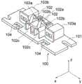
图8是示出第一实施例中的安装在图像形成装置的装置主体上的端子板的放大透视图;8 is an enlarged perspective view showing the terminal board mounted on the apparatus main body of the image forming apparatus in the first embodiment;
图9A是示出第一实施例中的被提供在装置主体侧上的接触端子和调色剂盒(当调色剂盒被插入时)的纵剖视图;9A is a longitudinal sectional view showing a contact terminal and a toner cartridge (when the toner cartridge is inserted) provided on the apparatus main body side in the first embodiment;
图9B是示出第一实施例中的被提供在装置主体侧上的接触端子和调色剂盒(当完成调色剂盒的插入时)的另一纵剖视图;9B is another longitudinal sectional view showing the contact terminal and the toner cartridge (when the insertion of the toner cartridge is completed) provided on the apparatus main body side in the first embodiment;
图10是示出第一实施例中的被提供在装置主体侧上的接触端子和在支架中保持电路板的调色剂盒(当完成调色剂盒的插入时)的放大剖视图;10 is an enlarged cross-sectional view showing the contact terminals provided on the apparatus main body side and the toner cartridge holding the circuit board in the holder (when the insertion of the toner cartridge is completed) in the first embodiment;
图11是示出第一实施例中的被提供在装置主体侧上的接触端子和未在支架中保持电路板的调色剂盒(当完成调色剂盒的插入时)的放大剖视图;11 is an enlarged cross-sectional view showing the contact terminals provided on the apparatus main body side and the toner cartridge (when the insertion of the toner cartridge is completed) in which the circuit board is not held in the holder in the first embodiment;
图12是示出比较例中的被提供在装置主体侧上的接触端子和未在支架中保持电路板的调色剂盒的放大剖视图;12 is an enlarged cross-sectional view showing the contact terminal provided on the apparatus main body side and the toner cartridge in which the circuit board is not held in the holder in the comparative example;
图13是示出第一实施例中的被提供在装置主体侧上的接触端子和未在支架中保持电路板的调色剂盒的放大剖视图;13 is an enlarged cross-sectional view showing the contact terminals provided on the apparatus main body side and the toner cartridge in which the circuit board is not held in the holder in the first embodiment;
图14A是示出第一实施例的第一修改中的装置主体侧上的接触端子和未在支架中保持电路板的调色剂盒的放大剖视图;14A is an enlarged cross-sectional view showing the contact terminals on the apparatus main body side and the toner cartridge not holding the circuit board in the holder in the first modification of the first embodiment;
图14B是第一实施例的第一修改中的调色剂盒的支架的放大透视图;14B is an enlarged perspective view of the holder of the toner cartridge in the first modification of the first embodiment;
图15是示出第一实施例的第二修改中的未在支架中保持电路板的调色剂盒的放大透视图;15 is an enlarged perspective view showing a toner cartridge in which a circuit board is not held in a holder in a second modification of the first embodiment;
图16A是示意性地示出本发明的第二实施例中的图像形成装置的端子板的透视图;16A is a perspective view schematically showing a terminal board of an image forming apparatus in a second embodiment of the present invention;
图16B是示意性地示出第二实施例中的图像形成装置的端子板的平面视图;16B is a plan view schematically showing a terminal board of the image forming apparatus in the second embodiment;
图16C是示意性地示出第二实施例中的端子板和信号线缆的透视图;16C is a perspective view schematically showing a terminal board and a signal cable in the second embodiment;
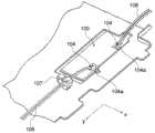
图17是示出第二实施例中的安装在图像形成装置的装置主体上的端子板(背面侧)和信号线缆的放大透视图;17 is an enlarged perspective view showing a terminal board (rear side) and a signal cable mounted on the apparatus main body of the image forming apparatus in the second embodiment;
图18是示出第二实施例中的安装在图像形成装置的装置主体上的端子板(接触端子侧)的放大透视图;18 is an enlarged perspective view showing a terminal board (contact terminal side) mounted on the apparatus main body of the image forming apparatus in the second embodiment;
图19是示出第二实施例中的安装在图像形成装置的装置主体上的端子板(接触端子侧)和信号线缆的放大透视图;以及19 is an enlarged perspective view showing a terminal board (contact terminal side) and a signal cable mounted on the apparatus main body of the image forming apparatus in the second embodiment; and
图20是示出第二实施例中的安装在图像形成装置的装置主体上的端子板(接触端子侧)和信号线缆的纵剖视图。20 is a longitudinal cross-sectional view showing a terminal board (contact terminal side) and a signal cable mounted on the apparatus main body of the image forming apparatus in the second embodiment.
具体实施方式Detailed ways
本发明的另外的适用范围将根据下文给出的具体实施方式而变得显而易见。然而,应当理解,虽然指示本发明的优选实施例,但是具体实施方式和特定示例仅通过说明的方式给出,这是因为对于本领域技术人员而言各种改变和修改将根据具体实施方式而变得显而易见。Further scope of applicability of the present invention will become apparent from the detailed description given hereinafter. It should be understood, however, that the detailed description and specific examples, while indicating the preferred embodiment of the invention, are given by way of illustration only since various changes and modifications will occur to those skilled in the art from the specific embodiment. become obvious.
将参照附图来描述本发明的实施例。在附图中所示的xyz正交坐标系中,x轴表示可拆卸单元的插入的方向(插入方向)(作为实施例中的可拆卸单元的调色剂盒的长边方向)。在xyz正交坐标系中,y轴表示可拆卸单元的宽度的方向(实施例中的调色剂盒的短边方向)。在xyz正交坐标系中,z轴表示可拆卸单元的高度的方向,其与x轴和y轴二者正交(实施例中的图像形成装置的高度的方向)。Embodiments of the present invention will be described with reference to the accompanying drawings. In the xyz orthogonal coordinate system shown in the drawing, the x-axis represents the direction of insertion (insertion direction) of the detachable unit (the longitudinal direction of the toner cartridge as the detachable unit in the embodiment). In the xyz orthogonal coordinate system, the y-axis represents the direction of the width of the detachable unit (the short-side direction of the toner cartridge in the embodiment). In the xyz orthogonal coordinate system, the z-axis represents the direction of the height of the detachable unit, which is orthogonal to both the x-axis and the y-axis (the direction of the height of the image forming apparatus in the embodiment).
第一实施例first embodiment
图1是示意性地示出本发明的第一实施例中的图像形成装置1的结构的纵剖视图。图像形成装置1例如是电子照相彩色打印机。如图1中所示,图像形成装置1的装置主体至少包括外壳2和布置在外壳2中的引导部3。图像形成装置1还包括将电功率(电压)供应到图像形成装置1的组件的电源单元(电压供应单元)4、将驱动力供给到图像形成装置1的组件的驱动单元5(包括诸如电动机的驱动力生成单元、以及诸如齿轮的驱动力传递单元)、以及控制图像形成装置1的操作的控制部6。FIG. 1 is a longitudinal cross-sectional view schematically showing the structure of an image forming apparatus 1 in a first embodiment of the present invention. The image forming apparatus 1 is, for example, an electrophotographic color printer. As shown in FIG. 1 , the apparatus main body of the image forming apparatus 1 includes at least a casing 2 and a
图像形成装置1包括用于在电子照相过程中形成各种颜色的显影剂(调色剂)图像的图像形成部(图像形成单元)10W、10Y、10M、10C和10K、用于将对应颜色的调色剂供应到图像形成部10W、10Y、10M、10C和10K的调色剂盒(显影剂盒)20W、20Y、20M、20C和20K、以及用于供应诸如纸的记录介质P的介质供应部分(供纸单元)30。图像形成装置1还包括输送记录介质P的介质输送部分(介质输送部)40、包括用于转印由图像形成部10W、10Y、10M、10C和10K所形成的彩色调色剂图像的中间转印带51的中间转印单元(转印带单元)50、用于将从中间转印带51转印的调色剂图像定影到记录介质P上的定影单元60、以及用于将已通过定影单元60的记录介质P排出到布置在外壳2之外的堆叠器(堆叠部分)上的介质排出部分(排纸部)70。The image forming apparatus 1 includes image forming sections (image forming units) 10W, 10Y, 10M, 10C, and 10K for forming developer (toner) images of various colors in an electrophotographic process, Toner is supplied to the toner cartridges (developer cartridges) 20W, 20Y, 20M, 20C, and 20K of the
图1示出五个图像形成部10W、10Y、10M、10C和10K以及五个调色剂盒20W、20Y、20M、20C和20K,但在图像形成装置1中包括的图像形成部的数量和调色剂盒的数量可以是四个或更少,并可以是六个或更多。图1示出彩色打印机,但本发明可以应用于具有单个图像形成部的单色打印机。本发明也可以应用于包括装置主体以及诸如可以被插入到装置主体中和从装置主体取出的调色剂盒之类的可拆卸单元的其他类型的电气设备。例如,本发明可以应用于诸如复印机、传真装置以及多功能外围设备(MFP)之类的其他类型的电气设备。1 shows five
如图1中所示,介质供应部分30包括安装在外壳2中的介质盒(纸盒)31、用于一个一个地送出堆叠在介质盒31中的记录介质P的供纸辊(跳跃(hopping)辊)32、以及用于向介质输送部分40输送从介质盒31送出的记录介质P的辊对33。介质供应部分30可以具有用于检测介质盒31中的记录介质P的存在或不存在的介质传感器34。介质供应部分30的结构不限于图1中所示的示例并且可以具有另外的结构。As shown in FIG. 1 , the
图像形成部10W、10Y、10M、10C和10K通过电子照相过程分别形成白色(W)调色剂图像、黄色(Y)调色剂图像、品红色(M)调色剂图像、青色(C)调色剂图像、和黑色(K)调色剂图像。作为可拆卸单元的调色剂盒20W、20Y、20M、20C和20K分别包含白色调色剂、黄色调色剂、品红色调色剂、青色调色剂和黑色调色剂,并将它们分别供应到图像形成部10W、10Y、10M、10C和10K的对应的显影设备14。用户可以沿着布置在装置主体中的引导部3在插入方向(+x方向)上插入(滑动)调色剂盒20W、20Y、20M、20C和20K的每一个。通过在插入方向上插入它们,调色剂盒20W、20Y、20M、20C和20K的每一个的状态从拆卸状态变为附接状态。此外,用户可以沿着引导部3在与插入方向相反的取出方向(-x方向)上拉出(滑动)调色剂盒20W、20Y、20M、20C和20K的每一个。通过在取出方向上取出它们,调色剂盒20W、20Y、20M、20C和20K的每一个的状态从附接状态变为拆卸状态。调色剂盒20W、20Y、20M、20C和20K是本发明被应用于的可拆卸单元的示例。用于图像形成部10W和调色剂盒20W的调色剂可以是透明的调色剂,而不是白色调色剂。The
图像形成部10W、10Y、10M、10C和10K除了调色剂的颜色彼此不同之外具有与彼此基本上相同的结构。调色剂盒20W、20Y、20M、20C和20K除了调色剂的颜色彼此不同之外具有与彼此基本上相同的结构。图像形成部10W、10Y、10M、10C和10K的每一个包括:用作曝光设备的曝光单元(光学写头)11、被可旋转地支承并用作图像载体的感光鼓12、以及用于均匀地对感光鼓12的表面进行充电的充电辊13。图像形成部10W、10Y、10M、10C和10K的每一个还包括用于将调色剂供应到感光鼓12的表面上从而形成与已经通过利用曝光单元11的曝光而形成在感光鼓12的表面上的静电潜像对应的调色剂图像的显影设备14、以及用于清洁感光鼓12的表面的清洁片15。曝光单元11例如是包括LED阵列的LED头,所述LED阵列被配置成使得多个LED(发光二极管)设置在感光鼓12的轴方向上。曝光单元11接收基于每一种颜色的图像数据的驱动信号并利用与驱动信号对应的曝光光照射感光鼓12的表面。显影设备14包括形成用于包含调色剂的显影剂存储空间的调色剂存储构件、将调色剂供应到感光鼓12的表面的显影辊、以及将存储在调色剂存储构件中的调色剂供应到显影辊的供应辊。图像形成部10W、10Y、10M、10C和10K的结构不限于上述示例,并且可以具有不同的结构。The
如图1中所示,介质输送部分40包括输送从介质供应部分30供应的记录介质P的辊对41、42和43、以及检测记录介质P的介质传感器44、45和46。介质输送部分40的结构不限于图1中所示的示例并且可以具有不同的结构。As shown in FIG. 1 , the
如图1中所示,中间转印单元50包括用于可移动地支承中间转印带51的辊52、53、54、55、56和57、将图像形成部10W、10Y、10M、10C和10K的感光鼓12上的相应的调色剂图像转印到中间转印带51上的第一转印辊58W、58Y、58M、58C和58K、以及除去残留在中间转印带51的表面上的调色剂的清洁片59。转印到中间转印带51上的调色剂图像被第二转印辊47转印到记录介质P上。中间转印单元50的结构不限于图1中所示的示例并且可以具有不同的结构。本发明也可以应用于不具有中间转印单元50而将调色剂图像直接从图像形成部10W、10Y、10M、10C和10K转印到记录介质P上的图像形成装置。As shown in FIG. 1 , the
如图1中所示,定影单元60包括彼此压接的一对辊61和62。辊61是在其内部包含加热器的热辊,并且辊62是压靠着辊61的压力辊。当记录介质P上的未定影的调色剂图像经过定影单元60的辊61和62之间时,调色剂图像被热和压力定影到记录介质P上。定影单元60的结构不限于图1中所示的示例并且可以具有不同的结构。As shown in FIG. 1 , the fixing
如图1中所示,介质排出部分70包括辊对71、72、73和74,其每一个包括一对彼此面对并压接的辊。辊对71、72、73和74的每一个包括由驱动力旋转以输送记录介质P的辊。辊对71、72、73和74排出已经通过定影单元60到布置在外壳2之外的堆叠器上的记录介质P。介质排出部分70可以包括检测记录介质P的介质传感器75。介质排出部分70的结构不限于图1中所示的示例,并且还可以包括另外的辊对、用于检测记录介质P的经过的另外的传感器等。As shown in FIG. 1 , the
图1中所示的图像形成装置1还可以包括纸翻转机构,其将已经通过了定影单元60的记录介质P转向并且将翻转后的记录介质P送到介质输送部分40,以便在记录介质P的两个面上打印图像。The image forming apparatus 1 shown in FIG. 1 may further include a paper reversing mechanism that turns the recording medium P that has passed through the fixing
图2A和2B分别是示意性地示出如何沿着引导部3滑动作为第一实施例中的可拆卸单元的调色剂盒20(20W、20Y、20M、20C和20K中的任何一个)并且将其插入到装置主体中的透视图和剖视图。如图2A和2B中所示,图像形成装置1包括在外壳2中与y方向平行地设置的五个引导部3、以及附接到每一个引导部3的调色剂盒20(20W、20Y、20M、20C和20K中的任何一个)。如图2A和2B中所示,每一个引导部3包括具有接触端子102的作为基板的端子板100。如图2B中所示,用于保持电路板的支架210被提供在作为调色剂盒20的单元主体的框上。FIGS. 2A and 2B schematically show how to slide the toner cartridge 20 (any one of 20W, 20Y, 20M, 20C, and 20K) as a detachable unit in the first embodiment along the
图3是示出在图2B中的区域A1中提供的调色剂盒20的支架210的透视图,并且图4是示出在图2B中的区域A1中提供的调色剂盒20的支架210、被置于支架210中的电路板200、以及用于将支架中的电路板200固定到框的固定构件230(处于电路板200与固定构件230被附接之前的状态)的透视图。图5是示出在图2B中的区域A1中提供的调色剂盒20的支架210的放大透视图,并且图6是示出在图2B的区域A1中提供的调色剂盒20的支架210以及布置在支架210上的电路板200的放大透视图。调色剂盒20中的电路板200的支架210包括平面形状为近似矩形的凹部(即,凹陷部分)211、布置在凹部211中的多个肋状物(基部或者基础构件)212、第一定位构件(第一定位部分)213以及第二定位构件(第二定位部分)214。多个肋状物212的顶面在高度方面处于相同的水平上。电路板200的一个面(与在其上提供电极端子201的面相反)由多个肋状物212的顶面所支承。第一定位构件213开始接触于作为电路板200的前端的边200a(前边)并且在插入方向(+x方向)上定位电路板200。第二定位构件214开始接触于电路板200的与边200a不同的边200b并且在取出方向(-x方向)上定位电路板200。3 is a perspective view showing the
图7A是示出在图像形成装置1中的调色剂盒20的支架210中保持的电路板200的电极端子201侧的透视图。图7B是示出图像形成装置1中的调色剂盒20的电路板200的半导体元件202侧的透视图。优选的是,电路板200的电极端子201是平行于插入方向(+x方向)的平板状电极。例如,电路板200的衬底部在长度方面具有约15mm的尺寸,在宽度方面约10mm并且在厚度方面约1mm。半导体元件202包括存储元件并且存储诸如用于标识调色剂盒的标识信息之类的关于调色剂盒的信息。由存储元件所存储的信息可以包括各种信息,诸如指示所消耗的调色剂的量的信息、指示调色剂盒是否为新的调色剂盒的信息、以及指示调色剂的颜色的信息。7A is a perspective view showing the
图像形成装置1的装置主体包括引导部3和具有作为具有弹簧特性的弹簧的两个接触端子102的端子板100。调色剂盒20包括用于保持具有开始与接触端子102接触的两个电极端子201的电路板200的支架210。为了将调色剂盒20的状态从拆卸状态变为附接状态,用户通过在插入方向(+x方向)上沿着引导部3滑动调色剂盒20来将调色剂盒20插入到装置主体中。为了将调色剂盒20的状态从附接状态变为拆卸状态,用户通过在取出方向(-x方向)上沿着引导部3滑动调色剂盒20来将调色剂盒20从装置主体取出。支架210包括第一定位构件213,所述第一定位构件213当将在支架210中保持电路板200的调色剂盒20在插入方向上沿着引导部3滑动以插入时定位作为保持在支架中的电路板200在插入方向(+x方向)上的前端的前边200a。第一定位构件213包括作为切口部分(缝隙部分)的凹口215,所述凹口215被配置成使得当在取出方向(-x方向)上滑动未在支架210中保持电路板200的调色剂盒20(处于附接状态)时两个接触端子102通过所述凹口215。接触端子102的数量可以是一个并且可以是三个或更多。凹口215的数量可以是一个并且可以是三个或更多。凹口215应该优选地具有使得在调色剂盒20被插入到装置主体中和从装置主体取出时支架210不触碰接触端子102的形状。如果支架210中的凹口215的底面是光滑的(没有尖锐的部分)并且如果底面低于肋状物212,则即使当支架210的凹口215的底面在调色剂盒20被插入到装置主体中和从装置主体取出时触碰接触端子102时,也可以防止对接触端子102的损坏。The apparatus main body of the image forming apparatus 1 includes a
支架210包括定位作为保持在支架210中的电路板200在插入方向(+x方向)上的后端的边200b的第二定位构件214、以及形成在第一定位构件213和第二定位构件214之间的凹部211。第一定位构件213和第二定位构件214被形成在比肋状物212的顶面高的水平上。凹部211被形成在比肋状物212的顶面低的水平上。The
图8是示出第一实施例中的安装在图像形成装置1的装置主体上的端子板100的放大透视图。端子板100包括板部分101(印刷板),所述板部分101具有在其上布置作为弹簧的接触端子102的第一面和与第一面相反的第二面。换言之,端子板100在第一面(板部分101)上支承作为弹簧的两个接触端子102。端子板100还包括用于分别将两个接触端子102电连接到信号线缆的两个连接器103a和103b。每一个接触端子102是用作弹簧的L形的弹簧片构件。接触端子102以及连接器103a和103b通过印刷在端子板100的表面上的印刷布线而电连接。因此,接触端子102和信号线缆106经由连接器103a和103b电连接。弯曲成L形的接触端子102的顶部102a是开始与保持在支架210中的电路板200的电极端子201接触的接触部分。顶部102a例如通过将板构件弯曲成L形来形成。在其中在支架210中保持电路板200的调色剂盒20被插入到装置主体中的附接状态下,接触端子102处于与电极端子201接触。优选的是,接触端子102的顶部102a被镀有金。当负载从上施加到接触端子102的顶部102a时,接触端子102的顶部102a被压缩并且被下推向板部分101。当接触端子102的顶部102a上的负载被释放时,接触端子102的顶部102a通过接触端子102的弹性恢复力返回到其初始状态。在插入方向(+x方向)上与前端侧相反的后端侧上的接触端子102的端部102b是被固定到装置主体(例如更具体地为板部分101)的固定端。在插入方向(+x方向)上与后侧相反的前端侧上的接触端子102的另一端部102c是未被固定到板部分101的自由端。换言之,固定端被形成在插入方向上的接触端子102的后端侧上,并且自由端被形成在插入方向上的接触端子102的前端侧上。因此,如果负载从上施加到接触端子102的顶部102a(接触部分),则接触端子102的固定端(端部102b)用作支点,并且自由端侧(端部102c)被下推向板部分101。端子板100的结构不限于图8中所示的示例,并且各种修改是可能的。端子板100包括作为线缆导件的一部分的L形的凹口104,这将在第二实施例的描述中进行描述。FIG. 8 is an enlarged perspective view showing the
图9A是示出了第一实施例中的提供在装置主体侧上的接触端子102和调色剂盒20(当调色剂盒20被插入时)的纵剖视图,并且图9B是示出了第一实施例中的提供在装置主体侧上的接触端子102和调色剂盒20(当完成调色剂盒20的插入时)的纵剖视图。当在支架210中保持电路板200的调色剂盒20沿着引导部3被插入到装置主体中时,接触端子102使其状态从其中未向接触端子102施加负载的初始状态(图9A)变为其中接触端子102触及保持在支架210中的电路板200并被电路板200下推的接触状态(图9B)。当在支架210中保持电路板200的调色剂盒20处于附接状态(接触状态)时,接触端子102处于与电极端子201接触。当沿着引导部3从装置主体取出在支架210中保持电路板的调色剂盒20时,接触端子102从接触状态(图9B)返回到初始状态(图9A)。9A is a longitudinal sectional view showing the
图10是示出第一实施例中的提供在装置主体侧上的接触端子102和调色剂盒20(保持电路板200)(当完成调色剂盒20的插入时)的放大剖视图。如图10中所示,当在支架210中保持电路板200的调色剂盒20沿着引导部3被插入到装置主体中时,接触端子102的形状从其中未施加负载的初始状态(图9A)变为其中接触端子102开始接触于或触及保持在支架210中的电路板200并由此被下推的接触状态。10 is an enlarged cross-sectional view showing the
图11是示出第一实施例中的提供在装置主体侧上的接触端子102和调色剂盒20(未在支架210中保持电路板200,即,在支架210中未保持电路板)(当完成调色剂盒20的插入时)的放大剖视图。如图11中所示,支架210包括第二定位构件214,所述第二定位构件214定位保持在支架210中的电路板200在插入方向(+x方向)上的后端以及第一定位构件213和第二定位构件214之间的凹部211,并且当未在支架210中保持电路板200的调色剂盒20处于附接状态时,接触端子102的至少部分(例如,更具体而言,顶部102a)位于凹部211中。11 is a diagram showing the
图12是示出作为未在支架210a中保持电路板200的可拆卸单元的调色剂盒20a和提供在装置主体侧上的接触端子102的比较例的放大剖视图。如图12中所示,第一定位构件213a不具有凹口(对应于图5中的凹口215的部分)。图12示出其中未在支架210a中保持电路板200的调色剂盒20a沿着图像形成装置的引导部被拉出(取出)装置主体的状态。当用户沿着引导部将调色剂盒20a滑动到装置主体中时,处于其初始状态的接触端子102触及调色剂盒20a的支架210a的前端侧上的第一定位构件213a(电路板的定位部分)并且由此暂时被下推。当完成插入时,接触端子102通过其弹性恢复力返回到初始状态并且进入到调色剂盒20a的支架210a的凹部211a中(电路板200应存在于其中的空间)。如图12中所示,如果用户通过沿着引导部滑动调色剂盒20a来拉出处于该状态的调色剂盒20a,则当接触端子102从调色剂盒20a的支架210a的凹部211a出来时,接触端子102可能被调色剂盒20a的支架210a的前端侧上的定位构件213a捕获,并且由此可能被损坏。12 is an enlarged cross-sectional view showing a comparative example of the
图13是示出第一实施例中的被提供在图像形成装置1的装置主体侧上的接触端子102和在支架210中未保持电路板200(即,未在支架中保持电路板)的调色剂盒20的放大剖视图。如图13中所示,第一定位构件213包括凹口215(对应于图5中的凹口215)。图13示出在其中在支架中未保持电路板200的调色剂盒20沿着引导部3被拉出装置主体的状态。当用户沿着引导部3将调色剂盒20滑动到装置主体中时,处于其初始状态的接触端子102通过调色剂盒20的支架210的凹口215。当完成插入时,接触端子102仍处于其初始状态,并位于调色剂盒20的支架210中的凹部211(电路板200应存在于其中的空间)中(图11)。在该状态下,调色剂盒20的锁定构件与装置主体中的构件啮合,并且被置于预定的位置。如图13中所示,当用户通过沿着引导部3滑动调色剂盒20来拉出处于附接状态的调色剂盒20时,位于调色剂盒20的支架210的凹部211中的接触端子102通过凹口215而不被调色剂盒20的支架210的前端侧上的第一定位构件213捕获。因此,图13中所示的示例中的接触端子102不被损坏。13 is a diagram showing the
如上所述,在根据第一实施例的图像形成装置1和调色剂盒20中,凹口215被布置在调色剂盒20的框(单元主体)中以使得接触端子102不触及或触碰框,并且即使调色剂盒20在附接状态下不在支架210中具有电路板200,当从装置主体拉出调色剂盒20时接触端子102也不会被损坏。As described above, in the image forming apparatus 1 and the
第一实施例的第一修改First Modification of First Embodiment
图14A是示出根据第一实施例的第一修改的图像形成装置中的装置主体的接触端子和未在支架210b中保持电路板的调色剂盒20b的放大剖视图。图14B是图14A中的支架210b的放大透视图。在图14A和14B中,与图13中所示的组件相同或对应的组件通过与在图13中使用的相同的附图标记来表示。在图14A和14B中所示的示例中,支架210b的形状不同于图13中所示的形状。在图14A和14B中所示的示例中,与图5中的肋状物212的顶面对应的面212b跨不包括支架210b的凹部211b的区域而形成,与凹口215对应的部分(凹口或切口部分)215b的底部(顶面)处于与面212b相同的水平上。换言之,面212b与部分215b形成平坦面。与凹口215对应的部分215b形成在支架210b在x方向上的端部上。在该示例中,支架210b的面212b触碰接触端子102,但由于没有构件具有使得接触端子102被捕获的形状,所以当调色剂盒20b在取出方向上被拉出时,对接触端子102的损坏可以被防止。此外,接触端子102不进入凹部211b。另外,支架210b中的面212b可以被配置为不触碰接触端子102。在其他方面,图14A和14B中所示的示例与图13中所示的示例相同。14A is an enlarged cross-sectional view showing the contact terminals of the apparatus main body and the
第一实施例的第二修改Second Modification of First Embodiment
图15是示出根据第一实施例的第二修改的图像形成装置中的在支架中未保持电路板的调色剂盒20c的部分的放大透视图。在图15中,与图5中所示的组件相同或对应的组件通过与在图5中使用的相同的附图标记来表示。在图15中所示的示例中,第一定位部分216的形状与图5中所示的形状不同,并且凹口217的形状与图5中所示的形状不同。在图15中所示的示例中,第一定位部分216形成在支架210在y方向上的两端附近而不是形成在支架210在y方向上的中心。接触端子102通过的凹口217形成在支架210在y方向上的中心周围。由于没有构件具有使得接触端子102被捕获的形状,所以当调色剂盒20c在取出方向上被拉出时,对接触端子102的损坏可以被防止。在其他方面,图15中所示的示例与图5中所示的示例相同。15 is an enlarged perspective view showing a portion of the
第二实施例Second Embodiment
在第一实施例中,电连接到接触端子102的连接器103a和103b被布置在安装在装置主体上的端子板100的接触端子102附近。如果将连接器103a和103b与图像形成装置1的控制部6连接或将连接器103a和103b与相邻的端子板100的连接器连接(串联)的信号线缆106被布置在接触端子102被布置在其上的端子板100的板部分(印刷板)101的面上,则信号线缆106可能在其触碰正在滑动的调色剂盒20时被损坏。In the first embodiment, the
在根据第二实施例的图像形成装置中,信号线缆106从端子板100的连接器103a和103b通过L形凹口104朝向背面(即,第二面)被路由并且固定在背面上。虽然在第一实施例中不限定信号线缆106的路由,但是第二实施例中的信号线缆106被路由到并且固定在端子板100的背面上。在其他方面,第二实施例与第一实施例(图1至11、图13至15)或比较例(图12)相同。In the image forming apparatus according to the second embodiment, the
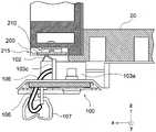
图16A至16C是示意性地示出根据本发明的第二实施例的图像形成装置的端子板100的视图。图16A是端子板100的透视图。图16B是端子板100的平面视图。图16C是示出了端子板100和信号线缆106的透视图。图17是示出从端子板100的背侧观察的在第二实施例中的图像形成装置的装置主体上安装的端子板100和信号线缆106的放大透视图。图18是示出在第二实施例中的图像形成装置的装置主体上安装的端子板100的放大透视图。图19是示出在第二实施例中的图像形成装置的装置主体上安装的端子板100和信号线缆106的放大透视图。图20是示出在第二实施例中的图像形成装置的装置主体上安装的端子板100和信号线缆106的纵剖视图。16A to 16C are views schematically showing a
如图16A至16C和图20中所示,连接器103a和103b具有信号线缆106被插入到其中的开槽103c。被插入到开槽103c中的信号线缆106沿着线缆导件(例如更具体地是,L形凹口104)从连接器103a和103b被布置在其上的第一面延伸到与第一面相反的第二面。如图16A和16B中所示,端子板100(例如更具体地是,L形凹口104)包括作为弯曲部的钩104a,其防止信号线缆106从L形凹口104出来。该结构防止被安置到L形凹口104的最深部分中的信号线缆106出来。如图17中所示,夹具107布置在支承端子板100的板材的背侧(或引导部3的背侧)上,并且夹具107保持信号线缆106。信号线缆106通过连接器103a和103b连接到接触端子102。优选的是,连接器103a和103b是具有两个连接端子的角连接器,所述两个连接端子被布置为彼此形成直角并通过连接其垂直向下线缆和水平线缆来将接触端子102和信号线缆106电连接。优选的是,角连接器包括配置成被信号线缆106插入并面对插入方向的开槽。在图18中所示的示例中,连接器103a和103b的开槽103c面对不同的方向。然而,优选的是,连接器103a和103b采用这样的方式进行布置:所有的开槽103c面对调色剂盒20在插入方向(+x方向)上的前端侧,这如图19和图20中所示。该结构使得当调色剂盒20被插入到装置主体中时避免信号线缆106和调色剂盒20之间的接触是可能的。线缆导件的结构不限于诸如L形凹口104的L形。端子板100可以包括作为线缆导件的一部分的通孔来使信号线缆106通过。As shown in FIGS. 16A to 16C and FIG. 20 , the
为了防止信号线缆触碰诸如调色剂盒的滑动构件,优选的是,例如,信号线缆被覆盖有盖构件,或连接到接触端子的连接器被布置在与接触端子被布置在其上的面相反的面上。然而,在第二实施例中的图像形成装置中,连接器103a和103b以及接触端子102被布置在端子板100的相同面上,连接到连接器103a和103b的信号线缆106通过L形凹口104被路由朝向端子板100的背面,并且信号线缆106被固定在端子板100的背面上。因此,在第二实施例中,可以通过简单的结构来防止对信号线缆106的损坏。In order to prevent the signal cable from touching a sliding member such as a toner cartridge, it is preferable that, for example, the signal cable is covered with a cover member, or that the connector connected to the contact terminal is arranged on the same surface as the contact terminal is arranged thereon. face on the opposite face. However, in the image forming apparatus in the second embodiment, the
在第二实施例中,信号线缆106的大部分跨端子板100被置于与调色剂盒20相反侧上,并且几乎不存在信号线缆106触碰调色剂盒20的可能性。即使当相邻的端子板100通过信号线缆106串联连接时,信号线缆106可以被路由在与调色剂盒20被布置在其上的面相反的面(引导部3的背面)上,并且布线的灵活性增加。In the second embodiment, most of the
用作线缆导件的端子板100的L形凹口104被形成在端子板100的端部附近。可替代地,用作线缆导件的通孔可以被形成在端子板100的中心附近的位置。如果通孔被用作线缆导件,则必要的是,将信号线缆106从它的端安置到通孔中。如果L形凹口104被用作线缆导件,则由于信号线缆106可以在给定的中间的点处被安置到L形凹口104中,所以将L形凹口104用作线缆导件促进了布线。The L-shaped
修改Revise
以上已经将作为包含显影剂的显影剂盒的调色剂盒描述为本发明被应用于的可拆卸单元的示例。本发明还可以应用于包括作为在其上形成静电潜像的图像载体的感光鼓的图像形成单元、包括形成在图像载体上的显影剂图像被转印到其上的中间转印带的转印带单元、包括将显影剂图像定影到记录介质上的定影辊的定影单元、以及被配置成使得它们通过滑动而插入到装置主体中以及从装置主体拉出的其他可拆卸单元。The toner cartridge, which is the developer cartridge containing the developer, has been described above as an example of the detachable unit to which the present invention is applied. The present invention can also be applied to an image forming unit including a photosensitive drum as an image carrier on which an electrostatic latent image is formed, a transfer including an intermediate transfer belt to which a developer image formed on the image carrier is transferred A belt unit, a fixing unit including a fixing roller that fixes a developer image onto a recording medium, and other detachable units configured such that they are inserted into and pulled out from the apparatus main body by sliding.
Claims (19)
Translated fromChineseApplications Claiming Priority (2)
| Application Number | Priority Date | Filing Date | Title |
|---|---|---|---|
| JP2014173860AJP6348379B2 (en) | 2014-08-28 | 2014-08-28 | Image forming apparatus and detachable unit |
| JP2014-173860 | 2014-08-28 |
Publications (2)
| Publication Number | Publication Date |
|---|---|
| CN106200308A CN106200308A (en) | 2016-12-07 |
| CN106200308Btrue CN106200308B (en) | 2020-09-25 |
Family
ID=53785426
Family Applications (1)
| Application Number | Title | Priority Date | Filing Date |
|---|---|---|---|
| CN201510425757.XAActiveCN106200308B (en) | 2014-08-28 | 2015-07-20 | Image forming apparatus and detachable unit |
Country Status (4)
| Country | Link |
|---|---|
| US (1) | US9459586B2 (en) |
| EP (1) | EP2990877B1 (en) |
| JP (1) | JP6348379B2 (en) |
| CN (1) | CN106200308B (en) |
Families Citing this family (4)
| Publication number | Priority date | Publication date | Assignee | Title |
|---|---|---|---|---|
| JP6361608B2 (en)* | 2015-08-28 | 2018-07-25 | 京セラドキュメントソリューションズ株式会社 | Image forming apparatus |
| JP6988452B2 (en)* | 2017-12-22 | 2022-01-05 | 富士フイルムビジネスイノベーション株式会社 | White toner for static charge image development, static charge image developer, toner cartridge, process cartridge, image forming apparatus and image forming method |
| JP7467063B2 (en)* | 2019-10-16 | 2024-04-15 | シャープ株式会社 | Image forming device |
| JP7362038B2 (en)* | 2019-11-22 | 2023-10-17 | 株式会社リコー | Detachable unit and image forming device |
Citations (7)
| Publication number | Priority date | Publication date | Assignee | Title |
|---|---|---|---|---|
| CN1459974A (en)* | 2002-05-17 | 2003-12-03 | 佳能株式会社 | Treating box and electronic photographing imaging apparatus |
| CN1459673A (en)* | 2002-05-17 | 2003-12-03 | 佳能株式会社 | Information storage medium, unit, process cartridge, developing cartridge and electrophotographic image forming apparatus |
| JP2007140266A (en)* | 2005-11-21 | 2007-06-07 | Oki Data Corp | Image forming apparatus |
| JP2009031376A (en)* | 2007-07-25 | 2009-02-12 | Canon Inc | Electrophotographic image forming apparatus |
| JP2011118160A (en)* | 2009-12-03 | 2011-06-16 | Sharp Corp | Connector and toner cartridge including the same, and image forming apparatus |
| CN103730744A (en)* | 2013-12-27 | 2014-04-16 | 深圳君泽电子有限公司 | Combined card connector and mobile phone |
| CN103969995A (en)* | 2013-01-31 | 2014-08-06 | 日本冲信息株式会社 | Replaceable unit, image forming apparatus that incorporates the replaceable unit |
Family Cites Families (13)
| Publication number | Priority date | Publication date | Assignee | Title |
|---|---|---|---|---|
| JP2001267765A (en)* | 2000-03-17 | 2001-09-28 | Seiko Epson Corp | Protective device for metal member and image processing system using the same |
| US6922534B2 (en)* | 2001-12-28 | 2005-07-26 | Canon Kabushiki Kaisha | Process cartridge and electrophotographic image forming apparatus having electrical connection for memory |
| JP3809375B2 (en)* | 2001-12-28 | 2006-08-16 | キヤノン株式会社 | Image forming apparatus |
| JP4794892B2 (en)* | 2005-04-11 | 2011-10-19 | キヤノン株式会社 | Process cartridge and electrophotographic image forming apparatus |
| JP2007199505A (en)* | 2006-01-27 | 2007-08-09 | Toshiba Corp | Developer supply device |
| KR100933290B1 (en)* | 2008-02-22 | 2009-12-22 | 삼성전자주식회사 | A memory unit, a developer cartridge, a developing apparatus and an image forming apparatus including the same |
| JP5454097B2 (en)* | 2009-11-20 | 2014-03-26 | 富士ゼロックス株式会社 | Detachable unit and image forming apparatus |
| JP5906579B2 (en)* | 2011-04-08 | 2016-04-20 | セイコーエプソン株式会社 | Terminal module and recording device |
| JP5765027B2 (en)* | 2011-04-08 | 2015-08-19 | セイコーエプソン株式会社 | RECORDING DEVICE AND TERMINAL MODULE FOR RECORDING DEVICE |
| US9079434B2 (en)* | 2011-09-30 | 2015-07-14 | Brother Kogyo Kabushiki Kaisha | Circuit board unit, cartridge, and manufacturing method thereof |
| JP6142519B2 (en)* | 2012-12-14 | 2017-06-07 | ブラザー工業株式会社 | Printing fluid supply apparatus and printing fluid cartridge |
| CN104163043B (en)* | 2013-05-17 | 2016-08-24 | 珠海纳思达企业管理有限公司 | Ink box chip, print cartridge and structure |
| JP2014102506A (en)* | 2013-11-29 | 2014-06-05 | Canon Inc | Manufacturing method of cartridge having storage elements and replacement method of storage elements of cartridge, cartridge, and image forming apparatus |
- 2014
- 2014-08-28JPJP2014173860Apatent/JP6348379B2/enactiveActive
- 2015
- 2015-07-15EPEP15176801.7Apatent/EP2990877B1/enactiveActive
- 2015-07-20CNCN201510425757.XApatent/CN106200308B/enactiveActive
- 2015-07-20USUS14/803,929patent/US9459586B2/enactiveActive
Patent Citations (7)
| Publication number | Priority date | Publication date | Assignee | Title |
|---|---|---|---|---|
| CN1459974A (en)* | 2002-05-17 | 2003-12-03 | 佳能株式会社 | Treating box and electronic photographing imaging apparatus |
| CN1459673A (en)* | 2002-05-17 | 2003-12-03 | 佳能株式会社 | Information storage medium, unit, process cartridge, developing cartridge and electrophotographic image forming apparatus |
| JP2007140266A (en)* | 2005-11-21 | 2007-06-07 | Oki Data Corp | Image forming apparatus |
| JP2009031376A (en)* | 2007-07-25 | 2009-02-12 | Canon Inc | Electrophotographic image forming apparatus |
| JP2011118160A (en)* | 2009-12-03 | 2011-06-16 | Sharp Corp | Connector and toner cartridge including the same, and image forming apparatus |
| CN103969995A (en)* | 2013-01-31 | 2014-08-06 | 日本冲信息株式会社 | Replaceable unit, image forming apparatus that incorporates the replaceable unit |
| CN103730744A (en)* | 2013-12-27 | 2014-04-16 | 深圳君泽电子有限公司 | Combined card connector and mobile phone |
Also Published As
| Publication number | Publication date |
|---|---|
| US9459586B2 (en) | 2016-10-04 |
| EP2990877B1 (en) | 2020-05-06 |
| JP2016048348A (en) | 2016-04-07 |
| JP6348379B2 (en) | 2018-06-27 |
| EP2990877A1 (en) | 2016-03-02 |
| US20160062313A1 (en) | 2016-03-03 |
| CN106200308A (en) | 2016-12-07 |
Similar Documents
| Publication | Publication Date | Title |
|---|---|---|
| US9188933B2 (en) | Power supply device and image forming apparatus | |
| JP2015138246A (en) | image forming apparatus | |
| US11754962B2 (en) | Image forming apparatus | |
| CN106200308B (en) | Image forming apparatus and detachable unit | |
| US8960853B2 (en) | Image forming apparatus and exposure device | |
| JP7014064B2 (en) | Heater unit, fixing device and image forming device | |
| CN105045057A (en) | Image forming apparatus | |
| CN102375391B (en) | Image processing apparatus and image forming apparatus | |
| US8811866B2 (en) | Image forming apparatus | |
| JP7024192B2 (en) | Power supply structure and image forming device | |
| JP7243226B2 (en) | Fixing device, image forming device | |
| JP2019152891A (en) | Image formation apparatus | |
| JP6180707B2 (en) | Electronics | |
| US9420131B2 (en) | Image forming apparatus having electrical unit projecting from top surface | |
| JP7211113B2 (en) | Fixing device, image forming device | |
| US9429908B2 (en) | Connector, process cartridge, and image forming apparatus | |
| JP2025074619A (en) | Drum unit | |
| JP6214745B2 (en) | Electronics | |
| JP6461268B2 (en) | Electronics | |
| CN103318668B (en) | Guide and image forming apparatus | |
| JP6520230B2 (en) | Electrical connection structure and image forming apparatus | |
| JP2016161906A (en) | Image formation device | |
| JP2020122813A (en) | Fixing device, image forming device | |
| JP2020086398A (en) | Image forming apparatus and medium supply apparatus |
Legal Events
| Date | Code | Title | Description |
|---|---|---|---|
| C06 | Publication | ||
| PB01 | Publication | ||
| SE01 | Entry into force of request for substantive examination | ||
| SE01 | Entry into force of request for substantive examination | ||
| GR01 | Patent grant | ||
| GR01 | Patent grant | ||
| TR01 | Transfer of patent right | ||
| TR01 | Transfer of patent right | Effective date of registration:20220401 Address after:Tiger gate, 1, 7, 12, Tokyo harbour, Japan Patentee after:Oki Electric Industry Co.,Ltd. Address before:Tokyo, Japan Patentee before:Oki Data Corp. |