CN106163422B - System and method for left atrial appendage occlusion - Google Patents
System and method for left atrial appendage occlusionDownload PDFInfo
- Publication number
- CN106163422B CN106163422BCN201480071851.3ACN201480071851ACN106163422BCN 106163422 BCN106163422 BCN 106163422BCN 201480071851 ACN201480071851 ACN 201480071851ACN 106163422 BCN106163422 BCN 106163422B
- Authority
- CN
- China
- Prior art keywords
- ligature
- atrial appendage
- left atrial
- delivery system
- assembly
- Prior art date
- Legal status (The legal status is an assumption and is not a legal conclusion. Google has not performed a legal analysis and makes no representation as to the accuracy of the status listed.)
- Expired - Fee Related
Links
Images


Classifications
- A—HUMAN NECESSITIES
- A61—MEDICAL OR VETERINARY SCIENCE; HYGIENE
- A61B—DIAGNOSIS; SURGERY; IDENTIFICATION
- A61B17/00—Surgical instruments, devices or methods
- A61B17/12—Surgical instruments, devices or methods for ligaturing or otherwise compressing tubular parts of the body, e.g. blood vessels or umbilical cord
- A61B17/12009—Implements for ligaturing other than by clamps or clips, e.g. using a loop with a slip knot
- A61B17/12013—Implements for ligaturing other than by clamps or clips, e.g. using a loop with a slip knot for use in minimally invasive surgery, e.g. endoscopic surgery
- A—HUMAN NECESSITIES
- A61—MEDICAL OR VETERINARY SCIENCE; HYGIENE
- A61B—DIAGNOSIS; SURGERY; IDENTIFICATION
- A61B1/00—Instruments for performing medical examinations of the interior of cavities or tubes of the body by visual or photographical inspection, e.g. endoscopes; Illuminating arrangements therefor
- A61B1/04—Instruments for performing medical examinations of the interior of cavities or tubes of the body by visual or photographical inspection, e.g. endoscopes; Illuminating arrangements therefor combined with photographic or television appliances
- A—HUMAN NECESSITIES
- A61—MEDICAL OR VETERINARY SCIENCE; HYGIENE
- A61B—DIAGNOSIS; SURGERY; IDENTIFICATION
- A61B17/00—Surgical instruments, devices or methods
- A61B17/04—Surgical instruments, devices or methods for suturing wounds; Holders or packages for needles or suture materials
- A61B17/0482—Needle or suture guides
- A—HUMAN NECESSITIES
- A61—MEDICAL OR VETERINARY SCIENCE; HYGIENE
- A61B—DIAGNOSIS; SURGERY; IDENTIFICATION
- A61B17/00—Surgical instruments, devices or methods
- A61B17/00234—Surgical instruments, devices or methods for minimally invasive surgery
- A61B2017/00238—Type of minimally invasive operation
- A61B2017/00243—Type of minimally invasive operation cardiac
- A—HUMAN NECESSITIES
- A61—MEDICAL OR VETERINARY SCIENCE; HYGIENE
- A61B—DIAGNOSIS; SURGERY; IDENTIFICATION
- A61B17/00—Surgical instruments, devices or methods
- A61B17/02—Surgical instruments, devices or methods for holding wounds open, e.g. retractors; Tractors
- A61B2017/0237—Surgical instruments, devices or methods for holding wounds open, e.g. retractors; Tractors for heart surgery
- A61B2017/0243—Surgical instruments, devices or methods for holding wounds open, e.g. retractors; Tractors for heart surgery for immobilizing local areas of the heart, e.g. while it beats
- A—HUMAN NECESSITIES
- A61—MEDICAL OR VETERINARY SCIENCE; HYGIENE
- A61B—DIAGNOSIS; SURGERY; IDENTIFICATION
- A61B17/00—Surgical instruments, devices or methods
- A61B17/04—Surgical instruments, devices or methods for suturing wounds; Holders or packages for needles or suture materials
- A61B17/0469—Suturing instruments for use in minimally invasive surgery, e.g. endoscopic surgery
- A61B2017/0475—Suturing instruments for use in minimally invasive surgery, e.g. endoscopic surgery using sutures having a slip knot
- A—HUMAN NECESSITIES
- A61—MEDICAL OR VETERINARY SCIENCE; HYGIENE
- A61B—DIAGNOSIS; SURGERY; IDENTIFICATION
- A61B17/00—Surgical instruments, devices or methods
- A61B17/30—Surgical pincettes, i.e. surgical tweezers without pivotal connections
- A61B2017/306—Surgical pincettes, i.e. surgical tweezers without pivotal connections holding by means of suction
- A—HUMAN NECESSITIES
- A61—MEDICAL OR VETERINARY SCIENCE; HYGIENE
- A61B—DIAGNOSIS; SURGERY; IDENTIFICATION
- A61B90/00—Instruments, implements or accessories specially adapted for surgery or diagnosis and not covered by any of the groups A61B1/00 - A61B50/00, e.g. for luxation treatment or for protecting wound edges
- A61B90/36—Image-producing devices or illumination devices not otherwise provided for
- A61B90/37—Surgical systems with images on a monitor during operation
Landscapes
- Health & Medical Sciences (AREA)
- Surgery (AREA)
- Life Sciences & Earth Sciences (AREA)
- Heart & Thoracic Surgery (AREA)
- Nuclear Medicine, Radiotherapy & Molecular Imaging (AREA)
- Vascular Medicine (AREA)
- Engineering & Computer Science (AREA)
- Biomedical Technology (AREA)
- Reproductive Health (AREA)
- Medical Informatics (AREA)
- Molecular Biology (AREA)
- Animal Behavior & Ethology (AREA)
- General Health & Medical Sciences (AREA)
- Public Health (AREA)
- Veterinary Medicine (AREA)
- Surgical Instruments (AREA)
Abstract
Translated fromChinese
Description
Translated fromChinese相关申请的交叉引用CROSS-REFERENCE TO RELATED APPLICATIONS
这个PCT申请是2013年12月30日提交的美国临时专利申请号61/921,985的非临时申请,并且要求该美国临时专利申请的优先权的权益。这个申请也要求于2014年12月24日提交的美国专利申请号14/582,868的优先权,且涉及2012年6月15日提交的美国专利申请号13/524,891。上述文件每一个的内容都在此通过引用并入。This PCT application is a non-provisional application of US Provisional Patent Application No. 61/921,985, filed December 30, 2013, and claims the benefit of priority to this US Provisional Patent Application. This application also claims priority to US Patent Application No. 14/582,868, filed December 24, 2014, and is related to US Patent Application No. 13/524,891, filed June 15, 2012. The contents of each of the aforementioned documents are hereby incorporated by reference.
背景技术Background technique
本发明的实施例涉及用于封堵患者的解剖结构的系统和方法。特殊实施例涉及用于封堵患者的左心耳的技术。Embodiments of the present invention relate to systems and methods for occluding a patient's anatomy. Particular embodiments relate to techniques for occluding the left atrial appendage of a patient.
房颤(AF)是一种心跳节律紊乱(或者“心率失常”),其中被称为心房的心脏的上腔室快速地而非以稳定节律颤动。这种快速颤动降低了心脏作为泵的适当功能的能力。AF的特征在于在连续周期中跨心房行进的电脉冲的圆形波。房颤是最普遍的临床心率失常,在美国影响超过200万人,并且在世界范围内影响约600万人。Atrial fibrillation (AF) is a heartbeat rhythm disorder (or "arrhythmia") in which the upper chambers of the heart, called the atria, fibrillate rapidly rather than at a steady rhythm. This rapid flutter reduces the heart's ability to function properly as a pump. AF is characterized by circular waves of electrical pulses traveling across the atrium in successive cycles. Atrial fibrillation is the most common clinical arrhythmia, affecting more than 2 million people in the United States and approximately 6 million people worldwide.
房颤通常增加导致许多潜在的致命性并发症的风险,包括血栓栓塞性中风、扩张型心肌病和充血性心力衰竭。生活质量也受到普通AF症状的影响,诸如心悸、胸部疼痛、呼吸困难、疲劳和晕眩。患有AF的人与具有正常窦性心律的人相比,平均发病率增加五倍,并且死亡率增加两倍。在美国每六个中风(每年约120,000)患者中有一个中风患者是患有AF的患者,并且与心脏节律紊乱相关的所有住院治疗患者(每年超过360,000)中的三分之一是由这种情况引起的,导致每年几十亿美元的健康护理费用。Atrial fibrillation often increases the risk of many potentially fatal complications, including thromboembolic stroke, dilated cardiomyopathy, and congestive heart failure. Quality of life is also affected by common AF symptoms such as palpitations, chest pain, dyspnea, fatigue and dizziness. People with AF had an average five-fold increase in morbidity and a two-fold increase in mortality compared with people with normal sinus rhythm. One in every six stroke patients in the United States (about 120,000 per year) is a patient with AF, and one third of all hospitalizations (over 360,000 per year) associated with cardiac rhythm disturbances are caused by this Circumstances result in billions of dollars in annual health care costs.
AF是医师最常见到的心律失常,并且随着人口老龄化,AF的流行快速增长。随着AF的流行增长,逐步显现出衰弱或者危及生命的并发症诸如中风的人口数也将增长。根据美国弗雷明汉心脏研究数据,AF患者中的中风比例从年龄50-59岁的人的约3%增长至年龄80或更高的人的超过7%。AF是造成高达35%的年龄超过85岁的人发生中风的原因。AF is the most common cardiac arrhythmia seen by physicians, and the prevalence of AF is growing rapidly as the population ages. As the prevalence of AF grows, so will the number of people who develop debilitating or life-threatening complications such as stroke. According to the Framingham Heart Study, the proportion of strokes among AF patients increases from about 3% in those aged 50-59 to more than 7% in those aged 80 or older. AF is responsible for stroke in up to 35% of people over the age of 85.
迄今为止,防止AF患者中风的努力主要关注于使用抗凝血剂和抗血小板药物,诸如华法林和阿司匹林。因此对具有一种或更多种中风风险因素的所有患者,包括所有年龄超过75岁的患者,推荐长期华法林治疗。然而,研究表明华法林倾向于是对AF的处方。虽然华法林将中风的风险降低60%或更多,但是年龄65-74岁的患者中仅40%并且年龄超过80岁的患者中仅20%服药,并且可能仅少于一半的人服用正确的剂量。患者是否愿意接受华法林存在问题,并且这种药物需要警惕性的血液监控,以降低出血性并发症的风险。To date, efforts to prevent stroke in AF patients have focused primarily on the use of anticoagulants and antiplatelet drugs, such as warfarin and aspirin. Therefore, long-term warfarin therapy is recommended for all patients with one or more stroke risk factors, including all patients over the age of 75 years. However, studies have shown that warfarin tends to be prescribed for AF. While warfarin reduces the risk of stroke by 60% or more, only 40% of those aged 65-74 and only 20% of those over 80 are taking the drug, and probably less than half are taking it correctly dose. Patient willingness to receive warfarin is questionable, and this drug requires vigilant blood monitoring to reduce the risk of bleeding complications.
电生理学家将AF分为“三P”:阵发性的、持续性的或永久性的。阵发性AF的特征在于持续不超过48小时的不定时发生的通常自限性发作——通常最适合治疗,而持续性或者永久性AF对已知的疗法的抵抗力大的多。研究人员现在已知AF是一种自持疾病,并且异常的心房节律趋向于开始或者触发更异常的节律。因而,与治疗方法无关地,患者经历的发作越多并且发作持续的时间越长,使心脏变为持续性正常节律的机会越小。Electrophysiologists classify AF into the "three Ps": paroxysmal, persistent, or permanent. Paroxysmal AF is characterized by sporadic, often self-limiting episodes lasting no more than 48 hours—usually best suited for treatment, while persistent or permanent AF is much more resistant to known therapies. Researchers now know that AF is a self-sustaining disorder and that abnormal atrial rhythms tend to initiate or trigger more abnormal rhythms. Thus, regardless of the method of treatment, the more episodes a patient experiences and the longer the episodes last, the less chance there is for the heart to go into a sustained normal rhythm.
AF的特征在于在连续周期中跨心房行进的电脉冲的圆形波,引起心脏的上腔室快速地颤动。已经识别了心房中这些波能够循环的至少六个不同的位置,这是一种为迷宫型消融治疗铺平道路的发现。近年来,研究人员已经识别了肺静脉可能是AF触发灶位于的最通常区域。被设计成隔离肺静脉或者消融特定的肺静脉灶的技术看起来非常有前途,并且是许多当前基于导管的消融技术研究的焦点。AF is characterized by circular waves of electrical impulses traveling across the atria in successive cycles, causing the upper chambers of the heart to rapidly quiver. At least six different locations in the atrium where these waves can circulate have been identified, a discovery that paved the way for labyrinth-type ablation treatments. In recent years, researchers have identified the pulmonary veins as possibly the most common area where AF triggers are located. Techniques designed to isolate pulmonary veins or to ablate specific pulmonary vein foci look very promising and are the focus of many current catheter-based ablation techniques.
AF导致的一种可能并发症是来自左心耳的凝块可能发生栓塞,并且导致对患者的伤害。例如,移开的凝块能够形成导致对患者的大脑、肾脏或者其它器官缺血性损伤的血栓。虽然左心耳封堵装置和技术当前可用,并且在其需要时向患者提供实际的益处,但是仍将作出显著进步以提供用于治疗左心耳的改进系统和方法。本发明的实施例提供对至少一些这些突出需求的解决方案和解答。A possible complication of AF is that clots from the left atrial appendage may embolize and cause harm to the patient. For example, a dislodged clot can form a thrombus that causes ischemic damage to the patient's brain, kidneys, or other organs. While LAA occlusion devices and techniques are currently available and provide real benefit to patients when they need it, significant advances will still be made to provide improved systems and methods for treating the LAA. Embodiments of the present invention provide solutions and answers to at least some of these outstanding needs.
发明内容SUMMARY OF THE INVENTION
本发明的实施例包括在外科手术期间治疗患者的解剖特征诸如左心耳的装置和方法。示范性技术包括使用具有拖尾箍构造的装置将成环缝合线输送至心耳。这些装置非常适合在最小侵入手术中使用。在一些情况下,装置的直径能够为1.5英寸或更小。在操作中,外科医生能够精确地并且高效地将装置的箍组件拖曳至患者体内的期望位置,并且使用该装置以将缝合线输送至患者的解剖体。Embodiments of the present invention include devices and methods for treating anatomical features of a patient, such as the left atrial appendage, during surgery. Exemplary techniques include delivering looped sutures to the atrial appendages using a device having a trailing cuff configuration. These devices are ideal for use in minimally invasive procedures. In some cases, the diameter of the device can be 1.5 inches or less. In operation, the surgeon can accurately and efficiently drag the cuff assembly of the device to the desired location within the patient and use the device to deliver the suture to the patient's anatomy.
一方面,本发明的实施例包括在将结扎线输送至患者的解剖特征时使用的系统和方法。例如,用于将左心耳结扎线施加给左心耳的结扎线输送系统可以包括具有近侧部和远侧部的伸长支撑机构、柔性箍组件和可收紧收缩构件。在一些情况下,柔性箍组件能够与伸长支撑机构的远侧部联接。在一些情况下,柔性箍组件能够包括与支撑框架联接的支撑本体。在一些情况下,支撑框架能够被偏压以将支撑本体保持在拖尾构造中,以便支撑本体的自由部被设置在伸长支撑机构的远侧部的近侧。在一些情况下,柔性箍组件的支撑框架能够与伸长支撑机构的远侧部联接。在一些情况下,支撑本体能够被构造成支撑可收紧收缩构件和左心耳结扎线的环。根据一些实施例,结扎线输送系统还能够包括绕左心耳收紧可收紧收缩构件的收缩构件控制机构。根据一些实施例,结扎线输送系统能够进一步包括绕左心耳收紧左心耳结扎线的结扎线控制机构。根据一些实施例,结扎线输送系统能够进一步包括相对于伸长支撑机构枢转的偏转器本体。在一些情况下,柔性箍组件的支撑框架能够通过偏转器本体与伸长支撑机构的远侧部联接。根据一些实施例,结扎线输送系统进一步能够包括偏转控制机构,该偏转控制机构与偏转器本体可操作关联,以便对偏转控制机构的致动引起偏转器本体相对于伸长支撑机构枢转。根据一些实施例,结扎线输送系统进一步能够包括适用于接纳可视化机构的管腔。In one aspect, embodiments of the present invention include systems and methods for use in delivering a ligature to an anatomical feature of a patient. For example, a ligature delivery system for applying a left atrial appendage ligature to the left atrial appendage may include an elongated support mechanism having a proximal portion and a distal portion, a flexible cuff assembly, and a retractable collapsible member. In some cases, the flexible cuff assembly can be coupled with the distal portion of the elongated support mechanism. In some cases, the flexible cuff assembly can include a support body coupled with the support frame. In some cases, the support frame can be biased to hold the support body in the trailing configuration so that the free portion of the support body is disposed proximal of the distal portion of the elongated support mechanism. In some cases, the support frame of the flexible cuff assembly can be coupled with the distal portion of the elongated support mechanism. In some cases, the support body can be configured to support the retractable collapsible member and the loop of the left atrial appendage ligature. According to some embodiments, the ligature delivery system can further include a retraction member control mechanism that retracts the retractable retractable member about the left atrial appendage. According to some embodiments, the ligature delivery system can further include a ligature control mechanism that tightens the left atrial appendage ligature around the left atrial appendage. According to some embodiments, the ligature delivery system can further include a deflector body that pivots relative to the elongated support mechanism. In some cases, the support frame of the flexible cuff assembly can be coupled with the distal portion of the elongated support mechanism through the deflector body. According to some embodiments, the ligature delivery system can further include a deflection control mechanism operatively associated with the deflector body such that actuation of the deflection control mechanism causes the deflector body to pivot relative to the elongated support mechanism. According to some embodiments, the ligature delivery system can further include a lumen adapted to receive a visualization mechanism.
另一方面,本发明的实施例包括将结扎线环输送至患者的左心耳的方法。示范性方法可以包括使结扎线输送系统的伸长支撑机构朝着患者的左心耳前进,其中结扎线输送系统包括与伸长支撑机构的远侧部联接的柔性箍组件,并且柔性箍组件被设置在拖尾构造中。在一些情况下,这些方法可以包括绕左心耳收紧可收紧收缩构件,以便收缩左心耳。在一些情况下,这些方法可以包括将结扎线环从柔性箍组件输送至已收缩的左心耳。在一些情况下,绕左心耳收紧可收紧收缩构件的步骤包括致动结扎线输送系统的收缩构件控制机构。根据一些实施例,柔性箍组件包括与支撑框架联接的支撑本体,并且支撑框架被偏压成将柔性箍组件保持在拖尾构造中,由此支撑本体的自由部被设置在伸长支撑机构的远侧部的近侧。在一些情况下,柔性箍组件通过偏转器本体与伸长支撑机构的远侧部联接,并且方法进一步能够包括使结扎线输送系统的偏转器本体相对于伸长支撑机构枢转。在一些情况下,结扎线输送系统包括与偏转器本体可操作关联的偏转控制机构,并且方法能够进一步包括致动偏转控制机构,以引起偏转器本体相对于伸长支撑机构枢转。在一些情况下,结扎线输送系统包括接纳可视化机构的管腔,并且方法能够进一步包括通过可视化机构使左心耳可见。在一些情况下,结扎线输送系统包括抽吸机构,并且方法能进一步包括将来自抽吸源的吸力传递至患者的左心耳。在一些情况下,抽吸机构包括抽吸壳,并且方法能够进一步包括将患者的左心耳的组织吸入抽吸壳中。In another aspect, embodiments of the present invention include methods of delivering a ligature loop to a left atrial appendage of a patient. An exemplary method may include advancing an elongated support mechanism of a ligature delivery system toward a left atrial appendage of a patient, wherein the ligature delivery system includes a flexible cuff assembly coupled with a distal portion of the elongated support mechanism, and the flexible cuff assembly is disposed in trailing construction. In some cases, the methods can include tightening the contractile member about the left atrial appendage to contract the left atrial appendage. In some cases, the methods may include delivering a ligature loop from the flexible cuff assembly to the retracted left atrial appendage. In some cases, the step of retracting the retractable retractable member about the left atrial appendage includes actuating a retractable member control mechanism of the ligature delivery system. According to some embodiments, the flexible hoop assembly includes a support body coupled to the support frame, and the support frame is biased to maintain the flexible hoop assembly in the trailing configuration, whereby the free portion of the support body is disposed in the elongated support mechanism The proximal side of the distal portion. In some cases, the flexible cuff assembly is coupled with the distal portion of the elongated support mechanism through the deflector body, and the method can further include pivoting the deflector body of the ligature delivery system relative to the elongated support mechanism. In some cases, the ligature delivery system includes a deflection control mechanism operably associated with the deflector body, and the method can further include actuating the deflection control mechanism to cause the deflector body to pivot relative to the elongated support mechanism. In some cases, the ligature delivery system includes a lumen receiving a visualization mechanism, and the method can further include visualizing the left atrial appendage through the visualization mechanism. In some cases, the ligature delivery system includes a suction mechanism, and the method can further include delivering suction from the suction source to the left atrial appendage of the patient. In some cases, the suction mechanism includes a suction shell, and the method can further include aspirating tissue of the patient's left atrial appendage into the suction shell.
在又另一方面,本发明的实施例包括与左心耳结扎线一起使用的结扎线输送系统。示范性结扎线输送系统能够包括伸长支撑机构以及与伸长支撑机构联接的柔性箍组件。柔性箍组件能够被偏压在拖尾构造中,由此柔性箍组件的自由部被设置在伸长支撑机构的远侧部的近侧。示范性结扎线输送系统也能够包括可收紧收缩构件。在一些情况下,柔性箍组件被构造成支撑可收紧收缩构件和左心耳结扎线的环。根据一些实施例,柔性箍组件包括被构造成接纳可收紧收缩构件的沟槽。在一些情况下,沟槽的一部分由翼片限定,所述翼片响应于由可收紧收缩构件施加的收紧力而柔性地皱缩。根据一些实施例,柔性箍组件包括被构造成接纳左心耳结扎线的环的沟道。在一些情况下,沟道的一部分由翼片限定,所述翼片响应于由左心耳结扎线的环施加的收紧力而柔性地皱缩。在一些情况下,结扎线输送系统能够进一步包括被构造成将来自抽吸源的吸力传递至患者的左心耳的抽吸机构。In yet another aspect, embodiments of the present invention include a ligature delivery system for use with a left atrial appendage ligature. An exemplary ligature delivery system can include an elongated support mechanism and a flexible cuff assembly coupled with the elongated support mechanism. The flexible cuff assembly can be biased in a trailing configuration whereby the free portion of the flexible cuff assembly is positioned proximal of the distal portion of the elongated support mechanism. Exemplary ligature delivery systems can also include a retractable collapsible member. In some cases, the flexible cuff assembly is configured to support a loop of the retractable collapsible member and the left atrial appendage ligature. According to some embodiments, the flexible cuff assembly includes a channel configured to receive the retractable collapsible member. In some cases, a portion of the channel is defined by a flap that flexibly collapses in response to a tightening force applied by the tightenable collapsible member. According to some embodiments, the flexible cuff assembly includes a channel configured to receive a loop of a left atrial appendage ligature. In some cases, a portion of the channel is defined by a flap that flexibly collapses in response to a tightening force applied by the loop of the left atrial appendage ligature. In some cases, the ligature delivery system can further include a suction mechanism configured to deliver suction from the suction source to the left atrial appendage of the patient.
为了更充分地理解本发明的性质和优点,应结合附图参考下文详细说明。For a fuller understanding of the nature and advantages of the present invention, reference should be made to the following detailed description taken in conjunction with the accompanying drawings.
附图说明Description of drawings
图1示出根据本发明的实施例的结扎线输送系统的多方面。Figure 1 illustrates aspects of a ligature delivery system according to an embodiment of the present invention.
图1A、1B和1C示出根据本发明的实施例的结扎线输送系统的多方面。1A, 1B and 1C illustrate aspects of a ligature delivery system according to embodiments of the present invention.
图2示出根据本发明的实施例的结扎线输送系统的多方面。2 illustrates aspects of a ligature delivery system according to an embodiment of the present invention.
图3示出根据本发明的实施例的结扎线输送系统的多方面。3 illustrates aspects of a ligature delivery system in accordance with embodiments of the present invention.
图3A示出根据本发明的实施例的结扎线输送系统的多方面。3A illustrates aspects of a ligature delivery system in accordance with embodiments of the present invention.
图4示出根据本发明的实施例的结扎线输送系统的多方面。4 illustrates aspects of a ligature delivery system in accordance with embodiments of the present invention.
图4A、4B和4C示出根据本发明的实施例的结扎线输送系统的多方面。4A, 4B and 4C illustrate aspects of a ligature delivery system according to embodiments of the present invention.
图5示出根据本发明的实施例的结扎线输送系统的多方面。5 illustrates aspects of a ligature delivery system in accordance with embodiments of the present invention.
图6示出根据本发明的实施例的结扎线输送系统的多方面。6 illustrates aspects of a ligature delivery system in accordance with embodiments of the present invention.
图6A和6B示出根据本发明的实施例的结扎线输送系统的多方面。6A and 6B illustrate aspects of a ligature delivery system according to embodiments of the present invention.
图7示出根据本发明的实施例的结扎线输送方法的多方面。7 illustrates aspects of a ligature delivery method according to an embodiment of the present invention.
图8示出根据本发明的实施例的结扎线组件的多方面。8 illustrates aspects of a ligature assembly in accordance with embodiments of the present invention.
图9示出根据本发明的实施例的结扎线组件的多方面。9 illustrates aspects of a ligature assembly in accordance with embodiments of the present invention.
具体实施方式Detailed ways
这里具体描述本发明的实施例的主旨以满足规定要求,但是本说明不必有意限制权利要求的范围。所要求保护的主旨可以具体化为其它方式,可以包括不同的元件或者步骤,并且可以与其它现有或者未来的技术结合使用。本说明不应被理解为暗示各种步骤或元件之间的任何特殊顺序或布置,除非在明确地描述单独步骤的顺序或元件的布置时。The subject matter of the embodiments of the invention is described in detail herein to meet specified requirements, but this description is not necessarily intended to limit the scope of the claims. The claimed subject matter may be embodied in other ways, may include different elements or steps, and may be used in conjunction with other present or future technologies. This description should not be read as implying any particular order or arrangement between the various steps or elements unless the order of individual steps or arrangement of elements is explicitly described.
所提出的装置的实施例提供用于向患者的解剖特征施加结扎线或者缝合线的输送系统和方法。在一些情况下,输送系统和方法能够与预先制作的结扎线组件或者预先打结的缝合线绳环一起使用。例如,结扎线组件或者勒除器设备可以包括缝合线或者绳,所述缝合线或者绳以单向结或者吊颈结系紧,或者以其它方式构造有单向控制机构,诸如棘轮。结或者棘轮机构可以由输送系统的远侧特征保持,以便随着操作者向近侧拉动近侧尾绳部,结或者棘轮由于处于结的远侧的绳的成环部被收紧而紧贴远侧特征。以这种方式,外科医生或者用户能够向绳结和近侧绳尾施加相反的力,以便绕解剖特征诸如左心耳拉紧绳环。通常作为一次性装置提供结扎线组件。Embodiments of the proposed device provide delivery systems and methods for applying ligatures or sutures to anatomical features of a patient. In some cases, the delivery system and method can be used with pre-made ligature assemblies or pre-knotted suture loops. For example, a ligature assembly or snare device may include a suture or string that is fastened in a one-way or sling knot, or otherwise configured with a one-way control mechanism, such as a ratchet. The knot or ratchet mechanism can be retained by a distal feature of the delivery system so that as the operator pulls the proximal tail rope proximally, the knot or ratchet snugly fits as the looped portion of the rope distal to the knot is tightened Distal features. In this manner, the surgeon or user can apply opposing forces to the knot and proximal tail in order to tighten the loop around anatomical features such as the left atrial appendage. The ligature assembly is typically provided as a disposable device.
本文公开的结扎线输送装置系统能够与这些结扎线组件一起使用,以便提供用于将成环的结扎线绳输送至患者的解剖特征的高效和有效方法。这些技术允许用户或者外科医生易于绕患者的解剖体操纵远侧绳环,并且视需要控制远侧绳环的放置。此外,所提出的系统和方法可以允许外科医生或者操作者绕患者的解剖体稳固地收紧绳环,而不切入患者的组织。因此,例如,所提出的技术非常适合在微创方法中使用。The ligature delivery device systems disclosed herein can be used with these ligature assemblies to provide an efficient and effective method for delivering looped ligatures to a patient's anatomical features. These techniques allow the user or surgeon to easily maneuver the distal bight around the patient's anatomy and control the placement of the distal bight as needed. Furthermore, the proposed system and method may allow the surgeon or operator to securely tighten the loop around the patient's anatomy without cutting into the patient's tissue. Thus, for example, the proposed technique is well suited for use in a minimally invasive approach.
本发明的实施例提供用于执行左心耳的心外膜封堵的系统和方法。能够通过任何期望的手术接入形式,包括但是不限于胸骨切开术、左或者右胸廓切开术以及本文别处讨论的其它程序来使用这些系统和方法。Embodiments of the present invention provide systems and methods for performing epicardial occlusion of the left atrial appendage. The systems and methods can be used with any desired form of surgical access, including but not limited to sternotomy, left or right thoracotomy, and other procedures discussed elsewhere herein.
示范性系统可以包括能够被用于附着至组织并且扩展心耳的抓握装置或者抽吸构件,以便封堵装置或者阻断装置能够被输送至心耳基底。示范性实施例提供机械简单、用户友好的装置,这些装置能够被用于向患者组织施加多种结扎线组件或者封堵装置中的任何一种,这些装置易于加载和卸载这些结扎线组件,并且这些装置能够被用于将结扎线缝合线高效地输送至组织(例如,左心耳的基底),同时保护组织不受绕组织拉紧结扎线绳时原本可能发生的潜在切割作用的影响。Exemplary systems may include a grasping device or suction member that can be used to attach to tissue and expand the atrial appendage so that an occlusion or occlusion device can be delivered to the atrial appendage base. Exemplary embodiments provide mechanically simple, user-friendly devices that can be used to apply any of a variety of ligature assemblies or occlusion devices to patient tissue that facilitate loading and unloading of the ligature assemblies, and These devices can be used to efficiently deliver a ligature suture to tissue (eg, the base of the left atrial appendage), while protecting the tissue from potential cutting that might otherwise occur when the ligature is pulled tight around the tissue.
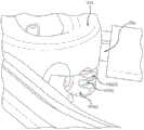
现在参考附图,图1示出根据本发明的实施例的结扎线输送系统100的多方面。如图所示,系统100包括具有箍组件122的绳输送机构120。箍组件122继而包括支撑本体126和支撑框架124。在一些情况下,支撑本体126能够被设置为挤出硅酮构件。在一些情况下,支撑框架或者支柱124能够被设置为镍钛诺丝。支撑本体和/或框架能够被称为拖尾箍机构。支撑本体126能够包括接纳或者容纳支撑框架124的凹进或者管腔127。此外,支撑本体126能够包括凹进或者沟道128,该凹进或者沟道128接纳收缩构件129,诸如可收紧特氟龙或者带特氟龙涂层的环。凹进、沟槽或者沟道128能够沿支撑本体126的长度延伸。Referring now to the drawings, FIG. 1 illustrates aspects of a
支撑本体126或者箍能够由框架或者支柱124支撑,并且继而缝合线绳和收缩构件129能够由支撑本体126支撑。如本文别处讨论,可以被设置为镍钛诺丝的支柱124能够被锚固至偏转器本体142或者系统100的一些其它可旋转或者固定特征,并且可以被设置为具有特殊横截面形状的硅酮挤出体或者壳体的支撑本体126能够容纳或者支撑收缩构件129和一根或更多根缝合线。根据一些实施例,支柱124可以包括不锈钢或者其它类似的材料,包括形状记忆材料。例如,支柱构件能够包括在施加力时弯曲但是不屈服并且当所施加的力被移除时恢复其原始形状的材料。也就是说,弯曲动作不向支柱构件引入变形。根据一些实施例,支撑本体126能够包括诸如硅酮、聚氨酯等的材料。The
在使用中,当收缩构件129被收紧或者收缩时,例如随着本体126的翼片或边缘121响应于收缩构件129的收紧力或者动作而折叠或者柔性地皱缩,收缩构件129能够从支撑本体126滑落或者被支撑本体126展开。因此,翼片或者边缘121能够向收缩构件或者缆129提供搁架或者引导。收缩构件129能够被视需要地绕解剖特征(例如,左心耳)拉紧,并且由于收缩构件129的大小或者尺寸,收紧力不引起收缩构件129切入解剖组织或者导致对解剖组织的损伤。收缩构件129能够被收紧为任何期望程度,以便将组织捏紧到止血位置。当收缩构件129处于绕解剖特征的期望位置时,一根或更多根缝合线或者结扎线能够被输送至解剖特征。通常,输送缝合线不包括以缝合线自身挤压组织,因为组织已经由于收紧的收缩构件129的存在而处于受挤压构造。在缝合线按需要放置后,收缩构件129能够被松开并且从解剖特征移除,使缝合线就位。然后,能够从患者体内缩回系统100。In use, when the
根据一些实施例,收缩构件129被设置为能够被支撑本体126的狭槽或者凹进127接纳或者位于凹进127中的带特氟龙涂层的可收紧缆。如本文别处所讨论,支撑本体能够被构造成保持或者支撑一根或更多根结扎线绳。支撑框架124能够向箍组件122提供一定程度的柔性,并且也能够通过箍组件122施加或者传递将被施加的一定量的力。According to some embodiments, the
根据一些实施例,结扎线输送系统100也可以包括收缩控制机构,该收缩控制机构能够操作以绕解剖特征诸如患者的左心耳收紧或者收缩该压缩构件129。收缩控制机构也可以操作以从解剖特征松开收缩构件。According to some embodiments, the
根据一些实施例,结扎线输送系统100也可以包括与绳输送机构120可操作关联的支撑机构130。如本文别处所讨论,支撑机构130可以具有接纳一个或更多个结扎线组件的第一接合组件以及与收紧控制机构联接的第二接合组件。According to some embodiments, the
如图所示,结扎线输送系统100也可以包括具有相对于支撑机构130枢转的偏转器本体142的偏转器组件140。偏转器组件140也能够包括相对于支撑机构130枢转的联动本体148。如本文别处所讨论,偏转器本体142也能够包括与一根或更多根结扎线绳连接或者保持或者支撑一根或更多根结扎线绳的特征。偏转器本体或者可旋转头142能够绕第一轴线144和/或第二轴线146旋转。偏转器本体142能够被设置为子远侧偏转器本体,因为偏转器本体142能够被设置在输送系统100上,设置在支撑机构130的远侧部132近侧的位置处,或者设置在系统的一些其它方面的更远侧部的近侧。如图所示,箍组件122的支撑框架124能够被锚固或者固定至偏转器本体142,以便偏转器本体142的运动能够被传递给箍组件122。在一些情况下,支撑框架或者支柱124能够操作以保持支撑本体126处于期望构造或者形状。As shown, the
根据一些实施例,结扎线输送系统100也能够包括偏转控制机构,该偏转控制机构与偏转器组件140联接,并且引起偏转器组件140的偏转器本体142相对于支撑机构130枢转。偏转控制机构可以包括例如可操作以使偏转器本体142绕轴线144和/或146旋转的手柄控制组件。偏转控制机构150也可以包括两个控制杆,其中第一控制杆152被构造成与偏转器本体的第一球143联接,并且第二控制杆(图1中未示出)被构造成与偏转器本体的第二球145联接。控制或者推/拉杆能够被用于将偏转器本体142旋转到期望位置中。在该意义上说,第一球142和具有用于可旋转地接纳该球的穴窝的对应杆152能够形成接头的一部分。杆的运动能够影响偏转器本体142的运动,并且因此能够影响箍组件122的运动。例如,当在远侧方向上向前推动杆时,偏转器本体142能够向上枢转(例如,绕轴线146),以便以箭头P1所示的朝着支撑机构130的类似的向上方式拉动箍组件122的自由部F。相反地,当在近侧方向上向后拉动杆时,偏转器本体142能够向下枢转(例如,绕轴线146),以便以箭头P2所示的离开支撑机构130的类似的向下方式拉动箍组件122的自由部F。According to some embodiments, the
偏转器本体142和联动本体148能够通过销或者其它枢轴机构联接在一起,以便提供这种枢转运动。以这种方式,偏转器本体142能够在俯仰运动中绕轴线146旋转。这些杆能够被沿支撑机构130的长度设置,并且通过操纵或者移动这些杆,偏转器本体142能够以各种自由度或者在一定运动范围内移动。在一些情况下,能够在杆上拉动并且能够推动其它杆,以便旋转偏转器本体142,并且继而使联动本体148以偏航运动绕轴线144旋转。柱体或者联动本体148能够可枢转地与支撑机构130附接,以促进或者使得能够进行这种旋转,并且支撑机构130或者其一部分能够在机械联动中起第三本体或者连杆的作用(例如,与联动本体148和偏转器本体142结合)。联动本体148能够在支撑机构130和偏转器本体142之间提供中间联动构件。对这些杆的控制能够影响具有俯仰和/或偏转运动的偏转器本体142和箍组件122的流畅运动。在一些情况下,偏转器本体142的运动能够操作以从箍组件122产生力或者将力从箍组件122施加在患者组织上。可选地,这种力能够与通过支撑机构130的一般运动施加的力组合。The
如图所示,运动的第一和第二轴线144、146允许操作者以关于轴线146的上下方式(俯仰),并且以关于轴线146的从一侧到另一侧的方式(偏航)旋转偏转器本体142,并且因此旋转箍组件122。在一些情况下,操作者能够操纵系统100,以便绕长轴线134旋转支撑机构130(滚转)。能够通过作为整体旋转该系统,或者通过实施一体旋转机构以提供这种滚转而实现滚转。As shown, the first and second axes of
偏转器组件140能够包括任何期望数目的连杆或者联动本体。这些连杆的构造和/或数目以及这些连杆之间的接头的构造和/或数目能够确定能够例如通过操作结扎线输送系统100的把手或者手柄将箍组件122操纵到的角度或者位置的范围。偏转器组件140能够被构造成使得操作者能够视需要将偏转器本体142和/或箍组件122移动至任何俯仰、偏航和/或滚转程度。The
在操作中,结扎线输送系统100能够被用于将一个或更多个结扎线环或者预系紧的缝合线输送至患者的解剖特征。例如,外科医生或者操作者能够使用结扎线输送系统100来将缝合线输送至患者的胸腺、患者的息肉、患者的阑尾、患者的左心耳等。In operation, the
在一些实施例中,由支撑本体126和偏转器本体142限定的箍的周长或面积在将缝合线施加至患者期间不减小。相反,收缩构件129的周长能够在将收缩构件129收紧或者收缩到身体附件或者解剖体上时缩小。In some embodiments, the perimeter or area of the cuff defined by the
如本文别处所讨论,结扎线输送系统100能够被以多种方式引入患者体内。例如,系统100能够通过左侧胸廓切开术接入点、右侧胸廓切开术接入点、胸骨切开术接入点或者剑状突起下接入点而放置到患者体内。As discussed elsewhere herein, the
箍组件122包括基底部B和自由部F,基底部B与偏转器本体142固定在一起,自由部F向后朝着支撑机构130的近侧段延伸。以此方式,自由部F能够朝着操作者或者外科医生向近侧延伸。在使用中,当结扎线输送系统100如箭头A所示前进到患者解剖体中或者朝着患者解剖体前进时,基底部B继续处于自由部F之前。因此,能够把自由部F视为拖尾部,并且箍组件122能够被视为拖尾箍,以便偏转器本体142(或者支撑机构130的远侧部132)继续处于箍组件122之前。因此,例如,当支撑机构向远侧前进时(例如,如箭头A所示),箍组件122能够被偏转器本体142拉动。相关地,箍组件122能够位于解剖特征诸如朝着操作者延伸的患者心脏的左心耳LAA之上。例如,在涉及胸骨切开方法的外科手术期间,随着患者躺成仰卧姿势,左心耳LAA离开患者的头并且向下朝着下肢延伸。外科医生或者操作者能够将箍组件122的自由部F位于LAA的末端之下,大致绕LAA放置箍组件122,并且使支撑机构130的远侧部132朝着LAA的基底(例如,朝着肺静脉PV)前进,以便偏转器本体142操作以沿着LAA的表面朝着心脏拖曳箍组件122。从这个意义上说,箍组件122的基底部B起箍组件的引导部的作用,并且箍组件的自由部F起箍组件的拖尾部的作用。箍组件122的基底部B或者引导部能够被力抵靠或者朝着心脏(例如,LAA的基底)推动或者前进,同时如箭头D所示在后方拖曳箍组件122的自由部F或者拖尾部。当视需要地定位箍组件122时,收缩构件129能够被展开,并且绕左心耳紧贴地收紧。The
应明白,图1中大致示出的心脏特征仅是为了例示而提供的。在人类解剖体方面,心脏具有四个腔室,在心脏的顶/后侧上有两个心房,并且在心脏的底/前侧上有两个心室。房室沟处于心房和心室之间的接合处,并且绕心脏的一部分延伸。左心耳在左心房上与心脏左侧上的房室沟相邻或者相切地出现,并且能够被视为在房室沟上倾斜,与左心室的小部分重叠。房室沟通常在左心耳所出现的点处与左心耳相切。在结扎线输送系统的操作期间,箍组件能够绕左心耳的基底定位,以便箍组件或者其一部分(例如,自由部F)能够放置在左心耳和左心室之间,与房室沟相邻。因此,房室沟能够在定位箍组件时向外科医生提供解剖线索或者视觉目标或者参考。结扎线输送系统的头或者远侧部能够位于左心耳的侧向部处或者侧向部上,以便头或者远侧部朝向左心耳的基底指向或定向,其中基底从左肺静脉向上折回。因此,左肺静脉能够在定位结扎线输送系统时向外科医生提供解剖线索或者视觉目标或者参考。类似地,外科医生能够使用位于在肺静脉离开肺并且附接到左心房时的肺静脉前面、位于进入正好处于它们上方的肺的左肺动脉之下的解剖凹口作为另一解剖线索或者视觉目标或者参考。外科医生能够在左心耳的末端之下滑动箍组件,以便箍组件在房室沟附近或者在房室沟中环绕左心耳的基底。It should be understood that the cardiac features generally shown in FIG. 1 are provided for illustration only. In human anatomy, the heart has four chambers, two atria on the top/posterior side of the heart, and two ventricles on the bottom/anterior side of the heart. The atrioventricular groove is at the junction between the atrium and the ventricle and extends around a portion of the heart. The left atrial appendage occurs on the left atrium adjacent or tangential to the atrioventricular groove on the left side of the heart, and can be seen as sloping over the atrioventricular groove, overlapping a small portion of the left ventricle. The atrioventricular communication is often tangent to the left atrial appendage at the point where it emerges. During operation of the ligature delivery system, the cuff assembly can be positioned about the base of the left atrial appendage so that the cuff assembly or a portion thereof (eg, free portion F) can be placed between the left atrial appendage and the left ventricle, adjacent the atrioventricular groove. Thus, the atrioventricular groove can provide an anatomical clue or visual target or reference to the surgeon when positioning the cuff assembly. The head or distal portion of the ligature delivery system can be positioned at or on the lateral portion of the left atrial appendage so that the head or distal portion is pointed or oriented toward the base of the left atrial appendage, where the base is folded back up from the left pulmonary vein. Thus, the left pulmonary vein can provide an anatomical clue or visual target or reference to the surgeon when positioning the ligature delivery system. Similarly, the surgeon can use the anatomical notch in front of the pulmonary veins as they exit the lung and attach to the left atrium, below the left pulmonary artery that enters the lung just above them, as another anatomical clue or visual target or reference. . The surgeon can slide the cuff assembly under the distal end of the left atrial appendage so that the cuff assembly surrounds the base of the left atrial appendage near or in the atrioventricular groove.
系统100能够通过左侧胸廓切开术接入点、右侧胸廓切开术接入点、胸骨切开术接入点或者剑状突起下接入点而放置到患者体内。能够使用这些接入路径中的任何一个来接近左心耳。The
如图1A的放大图中所示,偏转器本体142a能够包括用于保持缝合线的结(或多根缝合线的相应的结)的凹口142a(i)。偏转器本体142a也能够包括用于保持缝合线的绳的沟槽或者狭槽142a(ii)、142a(iii)。在使用中,缝合线能够被输送到左心耳上的位置或者收缩构件129a的位置以下的解剖特征。以这种方式,收缩构件不将缝合线捕获在组织上。位于下沟槽142a(ii)内的缝合线能够被展开,随后位于上沟槽142a(iii)内的缝合线能被展开。因此,缝合线不彼此缠在一起或者与收缩构件缠在一起。As shown in the enlarged view of FIG. 1A, the
如图1B的放大图所示,在一些实施例中,偏转器本体142b能够包括多个凹口(例如,用于保持多根缝合线的相应的结的凹口142b(i)和凹口142b(ii))。偏转器本体142b也能够包括用于保持缝合线的绳的沟槽或者狭槽。例如,沟槽或者狭槽142b(iii)和142b(iv)能够保持放置在凹口142b(i)处的缝合线的绳部。类似地,沟槽或者狭槽142b(v)和142b(vi)能够保持放置在凹口142b(ii)处的缝合线的绳部。As shown in the enlarged view of Figure IB, in some embodiments, the
在使用中,缝合线能够被输送至左心耳上的位置或者收缩构件位置下方的解剖特征。以这种方式,收缩构件不将缝合线捕获在组织上。位于下凹口和沟槽142b(i)、142b(iii)和142b(iv)内的缝合线能够被展开,随后位于上凹口和沟槽142b(ii)、142b(v)和142b(vi)内的缝合线能被展开。因此,缝合线能够依次展开,并且不彼此缠在一起或者与收缩构件缠在一起。In use, the suture can be delivered to a location on the left atrial appendage or to an anatomical feature below the location of the retraction member. In this manner, the constricting member does not capture the suture on the tissue. Sutures located within lower notches and
图1C示出根据本发明的实施例的示范性箍组件122c的多方面。如图所示,箍组件122c能够包括支撑本体126c和支撑框架124c。在一些情况下,支撑本体126c能够被设置为挤出硅酮构件或者铸造硅酮构件。在一些情况下,支撑框架或者支柱124c能够被设置为镍钛诺(镍钛)丝。支撑本体126c能够包括接纳或者容纳支撑框架124c的凹进或者管腔127c。在使用中,收缩构件(例如,可收紧的特氟龙或者带特氟龙涂层的环;未示出)能够自由地坐落在支撑本体126c的顶部以上或者坐落在该顶部上,与支撑本体大致成共面布置。Figure 1C illustrates aspects of an
如图所示,支撑本体126c包括上部128c(i)、第一翼片128c(ii)和第二翼片128c(iii)。上部128c(i)和第一翼片128c(ii)限定接纳结扎线或者缝合线的绳的沟道129c(i)。类似地,上部128c(i)、第一翼片128c(ii)或者其组合与第二翼片128c(iii)一起限定接纳结扎线或者缝合线的另一绳的沟道129c(ii)。在输送缝合线期间,翼片能够响应于收紧力或者缝合线的动作而柔性地折叠或者皱缩。As shown, the
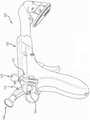
图2示出根据本发明的实施例的示范性结扎线输送系统200的多方面。这里所示的系统设有拖尾箍和拖尾抽吸机构。结扎线输送系统200包括图1的结扎线输送系统100中所包括的许多特征。例如,系统200能够包括具有箍组件221的绳输送机构205。结扎线输送系统200也能够包括抽吸机构210和相关联的抽吸控制机构220。抽吸机构210包括抽吸壳本体212、球214、抽吸壳216和用于将来自抽吸源(图2中未示出)的吸力传递给患者的导管218。在使用中,通过抽吸壳216施加给组织的吸力或者低压能够操作以将组织抽入壳216内部。当组织被抽吸壳216固定时,系统能够操作以移动或者重新定位抽吸壳216,抽吸壳216继而能够操作以移动或者重新定位组织。FIG. 2 illustrates aspects of an exemplary
抽吸壳本体212例如能够通过销或者枢轴机构可枢转地与联动本体230联接。以这种方式,抽吸壳本体212能够绕枢转轴线A相对于联动本体230枢转,如箭头P所示。为了实现这种枢转,系统能够包括可枢转地与抽吸机构210的球214联接的控制杆222。当控制杆222被朝着箭头1所示的远侧方向推动时,抽吸壳能够如箭头U所示向上或者朝着支撑机构的轴240(例如,朝着或者进入由支撑机构的轴240提供的弯头或者凹口242内)枢转。相反,当控制杆222被如箭头2所示朝着近侧方向拉动时,抽吸壳能够如箭头D所示向下或者离开支撑机构的轴240(例如,远离或者离开由支撑机构的轴240提供的弯头或者凹口242)枢转。因此,在控制杆222上的推动能够引起抽吸壳216前进到离开箍组件221的折起位置,并且在控制杆222上拉动能够引起抽吸壳216移出折起位置,并且朝着箍组件221或者甚至是穿过箍组件221移动。The
如图2中所示,联动本体230例如能够通过销或者枢轴机构可枢转地与偏转器本体250联接。以这种方式,偏转器本体250能够如箭头Q所示绕枢转轴线B相对于联动本体230枢转。在这个意义上说,抽吸壳216和箍组件221的支撑本体225每一个均能够绕它们自身相应的枢转轴线(例如,分别绕轴线A和轴线B)枢转。相关地,能够通过控制杆222的运动实现抽吸本体216的枢转,并且能够通过分开的或者独立的控制机构(例如,包括一个或更多个控制杆,诸如图1的控制杆152)的移动实现支撑本体225的枢转。在一些情况下,结扎线输送系统将提供联动构造,以便抽吸本体和支撑本体两者都绕公共的轴线枢转。联动本体230能够以类似于图1所示的联动本体148和支撑机构130之间的枢转联接的方式可枢转地与支撑机构260或者其轴240联接。As shown in FIG. 2, the
当抽吸壳216朝着轴240缩回或者缩回到凹进或者凹口242中,并且支撑本体225也朝着支撑机构260的轴240缩回时,系统200可以提供低姿态构造。当处在低姿态构造中时,系统200能够易于被医师或者操作者贯穿患者解剖结构的各种位置操纵。例如,系统200能够被放置到身体内,并且处于肋骨或者其它解剖体之间。支撑本体225能够被设置为易于压缩或者挤压的硅酮箍或者构件,在贯穿患者的解剖体引导系统200时提供小的阻力。类似地,可以包括镍钛诺材料的支柱226也能够以类似的方式压缩和挤压。一旦如所期望地相对于心脏或者左心耳(或者另一期望的解剖目标)定位,则箍组件能够弹开为宽开口形状。外科医生能够操作系统200,以便使箍组件221绕或者朝着左心耳(或者其它目标)降低或者前进,并且也使抽吸壳216朝着左心耳(或者其它目标)降低或者前进。支撑本体225能够沿着左心耳前进,以便使左心耳进入箍组件的中央孔口227内,并且支撑本体225能够被朝着左心耳的基底或者紧贴左心耳的基底放置。外科医生能够通过抽吸壳216向左心耳施加抽吸,以便将左心耳组织抽入或者吸入抽吸壳216的内部。抽吸壳216可以包括一个或更多个肋或者框架构件217,肋或者框架构件217能够起防止组织被抽吸到壳216中太远的作用,因而避免对组织造成潜在损伤,该潜在损伤否则可能由被施加至小面积组织的过于剧烈的抽吸力引起。以这种方式,能够通过抽吸壳216抽吸大表面积或者部分组织,允许外科医生使用该装置有效地操纵期望的解剖结构。换句话说,肋217或者支架能够不使组织向壳内部移入太远,因而避免对组织的过量拉伸、擦伤、损伤或者创伤。并且同时,肋217能够允许大表面积的组织仍被抽吸壳216接合,不减小被接合的组织的大小。例如,如果组织被抽吸到壳内部太远,则被设置在壳内(或者以其它方式暴露到或者接触吸力)的组织的表面积能够减小。肋217也能够防止组织阻碍或者密封抽吸导管218。因此,可以期望保持对大表面积组织的抽吸,并且保持组织离开孔口或者抽吸导管218。When the
在一些情况下,能够在系统200上放置套管,以便保持箍组件221为受约束或者低姿态位置。通过受约束的箍组件221,操作者能够在患者的解剖体内操纵低姿态构造的系统200。如本文别处讨论,支撑本体225和支柱226是柔性的,并且因此能够在应力或者所施加的力下被动地弯曲和变形,并且也能够在不再施加应力或者力时恢复它们的原始位置或者形状。对控制杆或者偏转器本体250的操作能够实现箍组件221的移动。因此,例如,控制杆能够经操作以将箍组件缩回为低姿态构造(例如,以便箍组件221与支撑机构260或者轴240并置),并且套管或者护套能够被放置在系统200的远侧端部上,这能够引起箍组件被动弯曲。然后,能够绕患者的解剖体操纵系统200,而不使箍组件221延伸至其能够卡在解剖体的各个部分上的位置。然后能够移除护套或者套管,因而允许箍组件221弹开,并且然后能够使用控制杆视需要地移动或者枢转箍组件221。In some cases, a cannula can be placed over the
在使用中,外科医生或者操作者能够操纵系统200,以便例如通过将支撑本体的一部分放置在左心耳的远侧末端或端部之下而绕左心耳放置支撑本体225。抽吸壳216能够接触左心耳或者抵靠左心耳定位,并且能够施加抽吸,以便将左心耳组织抽入抽吸壳中或者将左心耳抽入成抵靠抽吸壳。控制杆222能够被致动成使抽吸机构210绕轴线A枢转,因而穿过支撑本体225并且朝着支撑机构260或者轴240更远地抽吸左心耳。左心耳的这种运动或者定位能够允许外科医生或者操作者实现对解剖特征或者左心耳表面的增强可视化。由于轴线A和轴线B能够紧密对准或者共同对准,并且由于这些轴线能够位于靠近左心耳或者处于左心耳处,所以系统200特征(例如,抽吸壳本体212和/或偏转器本体250)的枢轴点能够定位成靠近左心耳的解剖弯曲或者枢轴点(例如,处于或者接近LAA的基底),以便抽吸壳本体212和/或偏转器本体250的运动产生左心耳的自然移动,而不在左心耳本身上施加不适当的应力。相关地,与左心耳的自由或者远侧端附接的壳216以更大的自由度移动。以这种方式,左心耳能够被系统200操纵,而不损伤患者的组织。In use, a surgeon or operator can manipulate the
通常,左心耳自然地位于或者坐落在心脏的表面上。随着心脏反复地收缩,左心耳稍微依附于心脏的表面或者曲面。在一些情况下,系统200能够位于左心耳处,并且能够在绕左心耳放置支撑本体225之前施加抽吸,以便将左心耳组织抽入抽吸壳216或者抽入左心耳组织抵靠抽吸壳216。然后,系统200能够被操纵或者定位以便绕左心耳放置支撑本体225。在一些情况下,这种步骤顺序能够被重复多次,以便使用抽吸抓握左心耳的末端,并且将LAA提升或者拉离心脏,支撑本体能够沿着LAA朝着基底前进,能够停止抽吸,支撑本体能够进一步前进等。在一些情况下,可能期望在使支撑本体前进为更靠近LAA的基底之前暂停施加抽吸,以便避免产生LAA的过量弯曲。根据一些实施例,抽吸壳216能够被用于视需要地升高或者操纵左心耳,并且能够使用显示仪或者观察仪器以可视化左心耳或者周围的心脏组织(例如,观察LAA的基底或者颈部)。Typically, the left atrial appendage is naturally located or rests on the surface of the heart. As the heart repeatedly contracts, the left atrial appendage is slightly attached to the surface or curved surface of the heart. In some cases, the
根据一些实施例,抽吸壳216能够被用于抓握左心耳的末端,并且操纵该末端穿过支撑本体225。然后能够停止抽吸,并且支撑本体能够沿着LAA进一步朝着基底前进。在使支撑本体225朝着LAA的基底前进的同时,可能期望前后(即,朝着和离开支撑机构260或者轴240)稍微枢转支撑本体。当支撑本体225被视需要地相对于左心耳定位时,外科医生或者操作者能够使用该系统,以将一个或更多个收缩构件或者缝合线输送至左心耳。通常,在将缝合线或者收缩构件输送至左心耳之后,外科医生或者操作者能够使切割器械沿着缝合线或者收缩构件的近侧尾朝着左心耳前进,并且然后夹住或者切割缝合线或者收缩工具的近侧尾或者绳。例如,使用近侧尾作为引导件,能够使一把弯曲的剪刀在远侧方向上沿着近侧绳尾前进。当剪刀到达绳结时,则剪刀能够被向后向近侧移动,并且然后用于切割缝合线。然后能够从患者身体移除被切断的近侧尾,使绳结和环(或者系带)绕LAA的基底就位。According to some embodiments, the
因此,如图2中所示,本发明的实施例包括结扎线输送系统,该结扎线输送系统具有双轴线构造,该双轴线构造带有可旋转或者可枢转的偏转器头,带有反抽吸设备。结扎线输送系统200能够以拉动模式操作,由此能够使用抽吸以朝着支撑本体225或者穿过支撑本体225抽吸左心耳,并且偏转器本体250和抽吸壳本体212的构造提供能够位于左心耳的基底处或者靠近左心耳的基底的可枢转点。支撑本体225能够提供在系统操作期间弯曲的柔性结构。系统能够被制造成包括处于拖尾构造的另外部件,该另外部件或附接至偏转器本体250(例如,类似于抽吸壳本体212和偏转器本体250之间的附接)或附接至特定设计的可枢转基底。诸如图2中具体化的那些拖尾构造独特地有益于使用伸长构件或者轴诸如支撑机构260的远侧部将环或者箍结构放置在解剖特征诸如左心耳之下。例如,能操纵系统,以便随着偏转器头被朝着左心耳的基底拉动或者前进,将箍抽吸或者拖曳到偏转器头后方,以便箍环绕左心耳。箍的近侧部能够在左心耳的末端之下滑动,该左心耳的末端通常朝向操作者或装置的近侧端指向或定向。以这种方式,引导头或偏转器头能够自然地放置在左心耳的基底处。Accordingly, as shown in FIG. 2, embodiments of the present invention include a ligature delivery system having a dual axis configuration with a rotatable or pivotable deflector head with a reverse suction equipment. The
图3示出根据本发明的实施例的示范性结扎线输送系统300的多方面。如图所示,系统300包括支撑机构360和具有箍组件321的绳输送机构305。箍组件321能够包括收缩构件329。3 illustrates aspects of an exemplary
根据一些实施例,图1和图2中所示的系统构造能够在剑状突起下和右侧胸廓切开方法手术中使用,并且图3和图4中所示的系统构造能够在胸骨切开术和左侧胸廓切开方法手术中使用。与图1和图2中所示的系统相比,图3和图4中的系统通常在支撑机构中提供少量弯曲,或者完全无弯曲。以这种方式,图3和图4中的系统呈现相对于支撑机构在明显角度的箍,以解决外科医生接近左心耳的方向。According to some embodiments, the system configuration shown in Figures 1 and 2 can be used in subxiphoid and right thoracotomy procedures, and the system configuration shown in Figures 3 and 4 can be used in sternotomy Surgery and left thoracotomy methods are used in surgery. Compared to the systems shown in Figures 1 and 2, the systems in Figures 3 and 4 typically provide little or no bending in the support mechanism. In this manner, the systems of Figures 3 and 4 present the cuff at a significant angle relative to the support mechanism to account for the surgeon's approach to the left atrial appendage.
在一些当前已知的右侧胸廓切开手术中,在患者的右侧引入装置,并且然后使其跨过胸部、在肺部之上穿过横窦、绕心脏的后部前进,并且到达心脏的左侧从而抵达左心耳。在一些情况下,这种方法可能难以可视化。一旦装置越过横窦,由于接近角度,可能就难以在左心耳处操纵该装置。例如,以下会是挑战性的:操纵具有引导或前进环的装置,使得引导环能够以适当的方式旋转或者枢转,以便促进在左心耳处输送结扎线。然而,通过本文公开的拖尾箍构造,能够高效地实现穿过这种路径接入左心耳。拖尾箍提供刚度充分的构造,这种构造能够向前越过横窦到达左心耳,在心脏的左侧上离开横窦,以便接近左心耳的基底。拖尾箍构造也非常适合在心包膜或者围心囊内侧上操纵。根据一些实施例,具有拖尾箍构造的装置能够在心脏的前表面上(例如,代替横跨横窦前进)在心包膜内部前进,以便越过心脏,并且下降到左心耳上。装置的远侧部(偏转器本体处或者附近)能够朝着左心耳的基底前进,并且箍的近侧部能够在左心耳的末端之下滑动。在一些情况下,除了使用结扎线输送系统将缝合线输送至左心耳之外,这些方法还可以包括向患者的心脏提供消融治疗。例如,外科医生或者操作者可以使用COBRA
如图3A的放大图中所示,箍组件321包括支撑本体325和支撑框架326。在一些情况下,支撑本体325能够被设置为挤出或者模制硅酮构件。在一些情况下,支撑框架或者支柱326能够被设置为镍钛诺丝。支撑本体和/或框架能够被称为拖尾箍机构。支撑本体325能够包括接纳或者容纳支撑框架326的凹进或者管腔。此外,支撑本体325能够包括接纳收缩构件329诸如可收紧特氟龙或者带特氟龙涂层的环或者缆的凹进或者沟道。凹进或者沟槽能够沿着支撑本体325的长度延伸。As shown in the enlarged view of FIG. 3A , the
在一些实施例中,支撑本体325能够包括多个孔或者孔口327、328。图3和3A中所示的支撑本体大致是扁平的,提供能够在左心耳之下高效地前进的低姿态。如图3中所示,支撑本体能够被构造成“U”或者马蹄铁形状。类似地,支撑本体325的横截面能够提供“U”或者马蹄铁形状。如图3A中所示,支撑框架326或者镍钛诺丝能够沿着支撑本体325的外部或周围部延伸,并且孔327、328能够被朝着支撑本体的内部定位。在使用中,缝合线绳能够被放置在孔的周围,放置支撑本体325提供的沟槽内部。可以由硅酮制成的铆钉(这里未示出)能够被放置孔内(例如,在支撑本体的顶段中的孔和支撑本体的底段中的对应孔之间延伸),由此将缝合线绳保持或者固位在支撑本体沟槽内的适当位置。在一些情况下,铆钉能够被构造成杠铃形状,以便铆钉的放大的相反端穿过支撑本体的对应的相反孔延伸(例如,其中铆钉的头坐落在支撑本体的顶和底表面外部)。In some embodiments, the
在一些情况下,两根绳能够被放置在支撑本体沟槽中,并且能够以交替方式绕每一个其它铆钉穿过,以便当外科医生或者操作者在一个缝合线绳上拉动时,随着缝合线绳离开支撑本体,缝合线绳切穿第一组铆钉,并且被输送至目标组织。类似地,外科医生能够在其它缝合线绳上拉动,随着该其它缝合线绳离开支撑本体,该其它缝合线绳切穿第二组铆钉,并且被输送至目标组织。在一些情况下,铆钉能够被胶粘至支撑本体的适当位置处,使得当切断铆钉的中央部时,端部或头仍保持附接至支撑本体,并且铆钉片不在患者体内的治疗点处喷出。以这种方式,铆钉能够被用于在展开之前将缝合线保持就位。并且在输送期间,缝合线绳能够被从支撑本体拉出。相关地,两根缝合线绳能够被加载到支撑本体上,并且在一根缝合线绳被拉出的同时,而另一根缝合线绳能保持就位。每根缝合线绳都能够通过其自身的相应一组铆钉保持就位,并且在一根缝合线上拉动能够操作以使专用于该缝合线的铆钉割裂。In some cases, two strands can be placed in the support body grooves and can be passed around each other rivet in an alternating fashion so that when the surgeon or operator pulls on one suture strand, the The string exits the support body, the suture string cuts through the first set of rivets, and is delivered to the target tissue. Similarly, the surgeon can pull on other suture strands that cut through the second set of rivets and are delivered to the target tissue as the other suture strands leave the support body. In some cases, the rivet can be glued in place to the support body so that when the central portion of the rivet is severed, the ends or heads remain attached to the support body and the rivet tabs are not sprayed at the treatment point in the patient out. In this manner, rivets can be used to hold the suture in place prior to deployment. And during delivery, the suture strands can be pulled out of the support body. Relatedly, two suture strands can be loaded onto the support body, and while one suture strand is pulled out, the other suture strand can remain in place. Each suture strand can be held in place by its own respective set of rivets, and pulling on one suture can operate to break the rivets dedicated to that suture.
大体上,图3和图3A示出用于结扎线输送系统300的固定头构造。这种构造可以包括一个旋转轴线,或者完全没有旋转轴线。在使用中,随着输送系统在患者身体内移动,箍组件被解剖特征偏转,支撑框架326可以相对于远侧头324弯曲。远侧头324可以包括狭槽或者凹进323,以便随着支撑框架相对于远侧头324向前和向后弯曲而接纳支撑框架326的基底。以这种方式,狭槽323能够分配支撑框架326的弯曲,以便支撑框架的基底以较大曲率半径(即,与当不存在狭槽时的基底中的弯曲相比)弯曲。因此,能以较低应力量实现支撑框架326内的更大程度的弯曲量。在操作中,柔性箍组件321能够明显地弯曲(例如,180度),不卡在患者的解剖特征上。在一些情况下,柔性箍组件321能够弯曲,以便其大致与支撑框架或者装置的伸长轴对准。例如,镍钛诺心轴或者支撑框架326能够为柔性的,以便箍组件和收缩构件响应于与固定解剖特征的接触而弯曲。然而,当在使箍组件321在心耳上前进时,镍钛诺心轴或者支撑框架326也能操作以朝着左心耳的基底施加向下的力或者其它力。根据一些实施例,箍组件321的两个或更多部件(例如,支撑本体325和收缩构件329)能够被设置在近似相同平面中,并且能够通过部件之间的临时或者弹性连接保持共面关系。In general, FIGS. 3 and 3A illustrate a fixation head configuration for a
当使用不具有可旋转接头的固定头构造时,诸如图3和3A中所示,外科医生或者操作者能够通过旋转与远侧头324为固定关系的把手而旋转该装置。在一些情况下,缆或者收缩构件329能够配合在支撑本体325的边缘或者沟槽内。在使用期间,缆329能够与支撑本体325一起移动。当被收紧时,缆329能够被拉出支撑本体325的沟槽或者凹进。在一些情况下,可能期望保持缆329和支撑本体325之间的对准。例如,结扎线输送系统能够具有保持缆329和支撑本体325在使用期间处于相同平面的结构。因此,缆329和支撑本体325能够在贯穿患者的解剖体操纵系统(例如,穿过胸腔、在肋骨之间等前进/缩回)时保持关于彼此的位置关系。缆329和支撑本体325可以不彼此方向联接,虽然它们能够易于随彼此弯曲。When using a fixed head configuration without a rotatable joint, such as shown in FIGS. 3 and 3A , the surgeon or operator can rotate the device by rotating the handle that is in fixed relationship with the
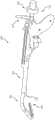
图4示出根据本发明的实施例的示范性结扎线输送系统400的多方面。如图所示,系统400包括近侧段402和远侧段404。远侧段404包括可枢转箍组件422,该可枢转箍组件422被构造成将一根或更多根缝合线绳输送至患者的解剖特征,诸如左心耳。4 illustrates aspects of an exemplary
如图4中所示,系统400能够包括一个或更多个滑块或者结扎线控制机构410、420。如图所示,滑块410、420处于向前或者远侧位置。这能够表示系统的开始或者初始构造,其中结扎线由箍组件的支撑本体保持。滑块或者结扎线控制机构能够在箭头A所示的近侧方向上移动,以便将相应的结扎线输送至期望的解剖特征,诸如左心耳。例如,滑块420能够被致动以输送第一结扎线,并且之后或者同时,滑块410能够被致动以输送第二结扎线。系统400也能够包括具有旋钮470和扳机480的收缩构件控制机构。在使用中,操作者能够向近侧拉动旋钮470,并且拉紧收缩构件。相关地,操作者能够向近侧拉动扳机480,并且松开收缩构件。在一些情况下,系统400可以包括允许逐渐拉紧收缩构件的棘轮机构(未示出)。对扳机的致动能够起释放棘轮机构(例如,与将收缩缆释放至打开位置的弹簧加载机构相关联)的作用。在一些情况下,系统400可以包括安全锁机构490,该安全锁机构490能够操作以锁定扳机480并且因而防止扳机被致动(即,使得收缩构件松开)直到期望松开收缩构件的时间为止。当操作者想要松开收缩构件时,操作者能够使安全锁机构490无效,并且继续致动扳机480,以便松开收缩构件。As shown in FIG. 4 , the
图4A示出箍组件422的放大图。如图所示,箍组件包括支撑本体425,支撑本体425例如通过支撑框架(如本文别处所述的)与偏转器本体424联接。偏转器本体424能够与系统400的远侧头427可枢转地联接。支撑本体425包括容纳结构426诸如管。FIG. 4A shows an enlarged view of the
图4B示出支撑本体425和容纳结构426的进一步放大图。容纳结构426包括管426a,管426a通过附接结构426b与支撑本体的上边缘425a联接(例如,在支撑本体的顶点425b处)。容纳结构426能够被用于在缝合线展开时帮助引导缝合线到达目标组织。相关地,容纳结构426能够操作以保持缝合线在收缩构件(例如,带特氟龙涂层的缆)以下,以便在缝合线展开时缝合线不将缆捕获在患者组织上。例如,收缩构件(未示出)能够离开偏转器本体424,并且穿过管或者引导器426a行进,并且沿支撑本体425的路径。能够使用非常柔软并且柔性的材料诸如硅酮或者聚氨酯来构造附接结构426b。因此,当缆或者收缩构件被引导器426a保持时,引导器426a能够被定位为与支撑本体425对准(例如,与这里所示的引导器426a的中央定位相比)。因此,引导器426a能够符合收缩构件的定位,并且当收缩构件处于支撑本体上或者与支撑本体对准时,引导器426a也是如此。FIG. 4B shows a further enlarged view of the
在使用中,收缩构件能够拉紧为较小直径(例如,小于支撑本体的直径),引导器426a能够跟随收缩构件(例如,通过朝着偏转器本体424移动)。以这种方式,引导器426a与附接结构426b结合,能够操作以保持缝合线位于收缩构件之下,所述缝合线可以沿支撑本体的沟槽425c定位(例如,在支撑本体的上边缘425a和下边缘425b之间)。随着收缩构件收缩,引导器426a能够最终接近或者接触患者组织,诸如左心耳。因此,在缝合线之上存在上部障碍,该障碍从支撑本体的顶点425b延伸至患者组织,并且缝合线能够从沟槽425c展开出来,并且展开到患者组织上。随着缝合线被拉紧,它们保持处于引导器426a和附接结构426b以下(例如,在组织和容纳结构之间)。这防止缝合线行进至收缩构件上方的位置(例如,以便容纳结构将处于缝合线和患者目标组织之间)。In use, the collapsing member can be tightened to a smaller diameter (eg, smaller than the diameter of the support body) and the
因而,收缩构件和支撑本体之间的柔性连接能够在收缩构件收缩时向缝合线提供引导。也就是说,随着缝合线收缩,缝合线被引导为保持在缆收缩构件以下,以便不将收缩构件或者其它装置元件捕获在患者组织上。Thus, the flexible connection between the constriction member and the support body can provide guidance to the suture when the constriction member is contracted. That is, as the suture is retracted, the suture is guided to remain below the cable retraction member so as not to trap the retraction member or other device elements on the patient's tissue.
虽然图4B中未示出,但是箍组件能够包括支撑该支撑本体425的柔性支撑框架或者心轴(诸如镍钛诺丝)。以这种方式,支撑本体425能够上下弯曲。箍组件也能够如图4A所示绕竖直轴线可控地旋转,以位于解剖体(例如,左心耳)下方。Although not shown in FIG. 4B , the hoop assembly can include a flexible support frame or mandrel (such as nitinol wire) that supports the
如图4C中所示,结扎线输送系统400c能够被设置在固定头构造中。在一些情况下,如图4中所示,结扎线输送系统能够被设置为单线可旋转头构造。在一些情况下,偏转器本体424能够绕图4A中所示的轴线A旋转。联动组件428也能够允许系统的远侧头427如图4所示从一侧到另一侧枢转(偏航)。例如,远侧头427能够在接头或者联动组件428处绕竖直轴线枢转。如图所示,系统400包括旋转盘或者偏航控件430,由此用户或者操作者能够通过旋转盘或者偏航控件430完成箍组件422的偏航。联动组件428也能够允许远侧头上下枢转(俯仰)。如图所示,系统400包括操作杆或者俯仰控件450,由此用户或者操作者能够通过致动操作杆450完成箍组件422中的俯仰。在一些构造中,对操作杆450的致动也能够或者可替选地操作以在接头或者联动组件428处完成从一侧到另一侧的运动。根据一些实施例,系统400能够包括与操作杆450可操作关联的扳机释放器455,以便操作杆450能够被锁定在期望位置中,因而将箍组件在期望构造中的定向锁定。图4中的远侧段404的曲率或者构造非常适合在右侧或者剑状突起下方法中使用。在俯仰或者偏航运动中操纵远侧头时,联动组件428能适应多个元件(例如,推杆、收缩缆、缝合线等)的存在以及操作或者致动。As shown in Figure 4C, the
与图1中所示的其中偏转器本体142具有由轴线144和轴线146提供的两个自由度的构造相比,图4A所示的构造具有由轴线A提供的一个自由度。图4A和4C中的箍组件所呈现的角度允许箍组件在左心耳下方前进,不具有与装置相关联的俯仰枢轴。箍组件也能够为充分柔性的(例如,在图4A和4C的构造中),以便能够从患者身体缩回装置,而不抵靠系统的伸长轴或者支撑机构主动地折起箍组件。The configuration shown in FIG. 4A has one degree of freedom provided by axis A as compared to the configuration shown in FIG. 1 in which
如图4C中所示,系统400c能够包括一个或更多个滑块或者结扎线控制机构410c、420c。如图所示,滑块410c、420c处于向前或者远侧位置。这能够代表其中结扎线由箍组件的支撑结构保持的系统的开始或者初始构造。滑块或者结扎线控制机构能够在箭头A所示的近侧方向上移动,以便将相应的结扎线输送至期望的解剖特征,诸如左心耳。例如,滑块420c能够被致动以输送第一缝合线,并且之后或者同时,滑块410c能够被致动以输送第二缝合线。系统400c也能够包括具有旋钮470c和扳机480c的收缩构件控制机构。在使用中,操作者能够向近侧拉动旋钮470c,并且拉紧收缩构件430c。相关地,操作者能够向近侧拉动扳机480c,并且松开收缩构件。在一些情况下,系统400c可以包括允许逐渐拉紧收缩构件的棘轮机构(未示出)。对扳机的致动能够操作以释放棘轮机构(例如,与将收缩缆释放至打开位置的弹簧加载机构相关联)。As shown in Figure 4C, the
图5示出具有滑块和缝合线控制机构510和520的结扎线输送系统500,滑块和缝合线控制机构510和520起缝合线接合组件的作用,并且能够在将缝合线输送至患者组织时使用。例如,当将缝合线加载到输送系统上时,外科医生、操作者或者其它个人能够绕支撑本体定位缝合线环,以便缝合线环放置在支撑本体的沟槽内。缝合线的结能够被放置在(例如,偏转器本体的)凹口内,并且能够向近侧拉动缝合线的近侧尾或者绳,以便移除可能保留在缝合线环内的过量缝合线或者松弛。缝合线的近侧尾或者绳能够与缝合线控制机构(例如,510或者520)附接。在使用中,缝合线控制机构能够被致动(例如,向近侧拉动),以便收紧或者收缩缝合线的远侧环。因此,系统的支撑机构530可以包括接纳一个或更多个结扎线组件的接合组件。系统500也可以包括与收缩构件可操作关联的旋钮或者缆收紧控制机构539。因此,用户能够在近侧方向上拉动收紧控制机构539,以便拉紧或者收缩该收缩构件。相关地,用户能够致动扳机或者释放机构(例如,如图4C中所示),以便松开该收缩构件。可选地,在一些构造中,用户能够在远侧方向上推动旋钮,以便松开该收缩构件。Figure 5 shows a
根据一些实施例,系统或者支撑机构530可以包括适用于接纳可视化机构诸如内窥镜的端口或者管腔534。根据一些实施例,输送系统500可以包括操作杆组件570。在使用中,操作者或者外科医生能够绕操作杆和显示仪放置橡胶带或者其它固定装置,以便保持显示仪在远侧方向上向前,并且防止显示仪在近侧方向上移动。在一些情况下,橡胶带或者固定装置能够操作以保持显示仪处于远侧位置,例如抵靠本文别处讨论的止挡件向远侧压紧。以这种方式,操作杆组件570能够有助于保持显示仪被定向在期望位置中。在一些情况下,操作杆组件570与固定装置结合,能够有助于保持显示仪不在管腔或者通道534内旋转。According to some embodiments, the system or
图6示出结扎线输送系统600,结扎线输送系统600具有可视化机构610,诸如显示仪。如这里所示,可视化机构610位于切口或凹进位置处,这能够有助于操作者或者外科医生对箍组件的致动和定位可视。可视化机构610能够位于系统的支撑机构或者伸长轴630的管腔内。如图6A中所示,可视化机构610能够被定位成处于支撑机构630中的弯头620的近侧。如图6B的切开横截面图所示,可视化机构610能够被定向在某个角度(例如,30度角),以便可视化机构的光学元件面向箍组件。Figure 6 shows a
在使用中,可以被设置为显示仪诸如内窥镜的可视化机构610能够被插入支撑机构630内,并且向远侧前进。再次参考图6,支撑机构630包括止挡件632,止挡件632操作以保持可视化机构610不从其所位于的管腔或者通道634延伸出去。因此,外科医生或者操作者能够将显示仪机构插入输送系统600的近侧部,并且使显示仪向远侧前进,直到显示仪机构的远侧部接触止挡件632为止。在一些情况下,输送系统600可以包括起将可视化机构610锁定就位的作用的锁定机构,以便防止或者禁止可视化机构在支撑机构630内或者相对于支撑机构630旋转。如图所示,支撑机构630包括偏置机构640,偏置机构640能够包括从支撑机构的本体延伸的两个翼部或者翼片642、644。In use, the
可视化构件的镜头612能够位于翼片642、644之间,以便翼片帮助保持组织离开镜头表面。以这种方式,镜头612能够保持不存在可能影响可视化构件获得的图像的流体、碎屑或者其它材料。例如,当存在于镜头上时,雾气、湿气和血液以及其它身体流体能够影响可视化构件的成像能力。如本文别处所讨论,可视化机构610能够被构造成镜头612相对于显示仪本体、支撑机构和/或箍组件以期望角度定向。以这种方式,在使用中,当箍组件展开或者被朝着解剖特征(例如,左心耳)引导时,用户能够同时可视解剖特征和箍组件。例如,当箍组件被展开或者朝着左心耳旋转时,对操作者或者外科医生呈现的视域包括左心耳,并且左心耳被箍组件围绕或者包围。操作者或者外科医生能够操纵系统600,以便箍组件放置在左心耳的末端的远侧部之上,并且因而呈现给操作者或者外科医生的图像类似于靶心或者目标,其中左心耳处于图像的中央部,并且箍组件处于周围。可视化机构的镜头和/或其它光学元件能够向用户提供足够宽的视域,以便用户能够在箍组件前后或者上下或者以贯穿运动范围的各个方向移动时观察箍组件。例如,视域足够宽,以便操作者能够看到箍组件贯穿运动范围的侧向运动或者偏航。在一些情况下,操作者能够在箍组件贯穿运动范围俯仰时观察箍组件的顶和底表面。在一些情况下,操作者能够观察箍组件的外边缘或者周围。The
由于可视化机构610与支撑机构630附接,所以镜头612提供的视域在患者体内随着外科医生或者操作者移动支撑机构而移动。在一些情况下,可视化机构610能够处于支撑机构630外部。在一些情况下,可视化机构610能够不与支撑机构630附接或者独立于支撑机构630。例如,在一些情况下,支撑机构能够穿过第一接入点插入到患者身体内,并且可视化机构能够插入第二接入点进入患者身体内。因此外科医生或者操作者可以保持可视化机构关于支撑机构固定。相关地,外科医生或者操作者可以独立于支撑机构操纵可视化机构,并且外科医生或者操作者可以独立于可视化机构操纵支撑机构。因此,在使用中,解剖特征诸如身体组织能够看起来在视域内保持固定(例如,当显示仪未与支撑机构联接时),或者解剖特征能够看起来在视域内移动(即,当显示仪被设置在支撑机构内时)。Since
如图6A中所示,可视化机构610的远侧部616能够从输送系统600的支撑机构630向近侧延伸。在一些情况下,可视化机构可以包括光源617或者与光源617相关联地操作。在一些情况下,可视化机构可以包括用于与相机或者其它记录装置附接的联接机构618。As shown in FIG. 6A , the
在图6B的剖视图中,能够看出止挡件632起防止可视化机构610从支撑机构630向远侧延伸的作用。如图所示,镜头612向操作者提供包括箍组件的视域。因此,通过提供与系统的远侧端偏置的显示仪或者可视化机构610,并且通过提供处于拖尾构造中的箍组件650,以便箍组件被设置在可视化构件或者镜头612的远侧,用户能够观察治疗点(例如,左心耳处)处的箍组件的操作,同时获得大致与输送系统的支撑机构或者本体对准的向远侧定向的视域,并且由于翼部的保护动作,镜头不接触患者组织。在一些情况下,可视化机构或者显示仪约30cm长并且直径约10mm。在一些情况下,镜头以约30度的角度与显示仪的本体偏置。支撑机构630能够被构造成接受或者接纳多种显示仪大小和形状中的任何一种。在一些情况下,外科医生或者操作者能够通过将一个显示仪从支撑机构移除,并且以不同的显示仪替换该显示仪而在单次手术的背景下使用多个显示仪。In the cross-sectional view of FIG. 6B , it can be seen that the
图7示出根据本发明的实施例的结扎线输送方法700的多方面。如图所示,一种将结扎线环输送至患者的左心耳的方法能够包括如步骤710所示使结扎线输送系统的伸长支撑机构朝着患者的左心耳前进。在一些情况下,结扎线输送系统包括与伸长支撑机构的远侧部联接的柔性箍组件,并且柔性箍组件被设置在拖尾构造中。此外,方法可以包括如步骤720所示绕左心耳收紧可收紧收缩构件,以便收缩左心耳。又进一步,方法可以包括如步骤730所示将结扎线环从柔性箍组件输送至已收缩的左心耳。7 illustrates aspects of a
本申请中所讨论的所有专利文件(包括专利、专利申请和专利公开)、科学杂志、书籍、论文、技术文献以及其它公开和材料都在此通过引用以其整体并入。All patent documents (including patents, patent applications, and patent publications), scientific journals, books, theses, technical literature, and other publications and materials discussed in this application are hereby incorporated by reference in their entirety.
结扎线组件ligature assembly
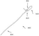
图8示出根据本发明的实施例的示范性结扎线组件800的多方面。在一些情况下,结扎线组件可以被称为结扎环或者手术勒除器。如图所示,结扎线组件800包括结扎线绳或者封堵装置或者机构。在一些情况下,结扎线组件能够被设置为左心耳结扎线组件。结扎线组件或者绳800能够以呈现结820和环部830的方式预先形成或者预先系紧。大体上,结820被朝着结扎线绳800的远侧部802设置。在使用中,能够拉动近侧尾部804,因而拉紧或者收紧结扎线环部830。8 illustrates aspects of an
根据一些实施例,结820被设置为单套结、滑结、活结等。例如,在用户或者操作者拉动近侧绳尾804时,结820能够允许穿过结820滑动的一部分绳在一个拉动方向上(例如,向近侧)自由地沿长度方向移动。以这种方式,结820能够用作止回结。结820可以被设置为简单的结或者复杂的结。适当的结构造也可以包括腹腔镜结、内窥镜结、体内结、体外结、腹内结、手术结等。在一些情况下,结扎线组件可以包括具有远侧环部和近侧尾部的带结绳或者缝合线。如本文别处进一步讨论,本公开中提供的结扎线输送系统和方法允许外科医生或者操作者绕患者的解剖体收缩环部830,而不使绳切入患者的组织或者在患者的组织中形成沟槽。According to some embodiments, the
如本文别处所讨论,结扎线输送系统可以包括接纳结扎线组件结820的凹口或者止挡件。在一些情况下,凹口或者止挡件可以包括带狭槽的搁架或者两个突起,在结扎线组件的近侧尾804被向近侧拉动时,带狭槽的搁架或者两个凸起起防止结相对于支撑机构或者偏转器机构向近侧平移。在使用中,外科医生或者操作者能够使用结扎线输送组件以绕解剖结构放置结扎线绳环830,并且能够向近侧拉动绳尾部804,以便相对于患者的解剖结构收紧绳环。因而,在通过结820向近侧拉动结扎线绳的平移部时,能使用轭或者止挡件来提供相反力,以便收紧或者缩小结扎线环的直径。以这种方式,结能够被凹口约束。绳的平移部穿过结820。以这种方式,能够通过经凹口施加反向牵引而收紧环绳。滑结在拉紧时能起固定自身的作用。一旦被相对于解剖结构拉紧到位,则能够从结扎线输送系统卸下缝合线绳环或者封堵装置,并且因而从凹口释放该结。此后,结扎线环或者封堵装置绕解剖结构(例如,通过带结的环)保持就位。能够从结扎线输送系统释放近侧尾部804,并且能够从患者体内移除或者缩回结扎线输送系统,留下固定至患者的解剖体的缝合线绳。然后,外科医生或者操作者能够夹住缝合线绳的过量近侧尾部。以这种方式,封堵装置或者结扎线环能够被用于系紧患者的左心耳、阑尾或者患者体内的任何其它期望结构。As discussed elsewhere herein, the ligature delivery system may include a notch or stop that receives the
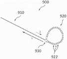
图9示出根据本发明的实施例的另一示范性结扎线组件或者勒除器900。如这里所示,结扎线组件包括近侧尾部910和远侧部920,远侧部920例如能够通过使近侧部穿过棘轮机构930而形成环。以这种方式,远侧部能够提供结扎线环或者封堵装置。远侧部包括一系列凸起922,该一系列凸起922可以包括齿、倒钩、珠等。通常,凸起被形成使得它们能够被易于在箭头A所示的一个方向上穿过棘轮机构930拉动,并且抵抗在箭头B所示的相反方向上穿过棘轮机构930的运动。例如,凸起可以是三角形形状,并且具有倾斜表面。以这种方式,凸起922和棘轮机构930之间的协同操作以类似于单向或者止回结的方式操作。在一些情况下,棘轮机构930可以包括在刚性凸起沿棘轮穿过时变形的柔性棘爪。一旦凸起越过棘轮或者棘爪(在箭头A所示的方向上),则防止或者禁止其以相反方式(箭头B所示)返回。以这种方式,能够视需要地将环或者封堵机构收紧或者收缩为特殊直径或者尺寸,并且当凸起被锁在棘轮或者棘爪上时,环不能扩展或者松开。FIG. 9 illustrates another exemplary ligature assembly or snare 900 in accordance with an embodiment of the present invention. As shown here, the ligature assembly includes a
在一些情况下,结扎线组件包括能够部分地位于管或者载体内的绳状缝合线。在一些情况下,缝合线被预先形成有结。因此,当结扎线的成环远侧端绕LAA位于期望位置时,能够拉动或者致动结扎线的近侧部,以便拉紧该环,因而固定该结。一些结扎线组件可以包括以环的形式从载体的远侧端延伸的缝合线,该缝合线具有当拉紧时固定自身的滑结。在一些情况下,结扎线组件包括不可被患者的身体吸收的缝合线。本发明的实施例包括与这些结扎线组件一起使用的用于将缝合线输送至患者的LAA的系统和方法。In some cases, the ligature assembly includes a rope-like suture that can be positioned partially within a tube or carrier. In some cases, the suture is pre-knotted. Thus, when the looped distal end of the ligature is in the desired position about the LAA, the proximal portion of the ligature can be pulled or actuated to tighten the loop, thereby securing the knot. Some ligature assemblies may include a suture extending from the distal end of the carrier in the form of a loop, the suture having a slip knot that secures itself when tensioned. In some cases, the ligature assembly includes sutures that are not absorbable by the patient's body. Embodiments of the present invention include systems and methods for use with these ligature assemblies for delivering sutures to a patient's LAA.
绳或者缝合线能够包括普通肠线元件、合成聚合物或者共聚物、聚合物纤丝、单纤维丝、聚酯或者其它适当的材料、带涂层构造、编织构造或者绳等。在一些情况下,缝合线绳的直径可以在约15至20千分之一英寸之间。在一些情况下,可以使用其它绳直径。应理解,结扎线输送系统可以包括绳引导器、狭槽、沟槽等,所述绳引导器、狭槽、沟槽等按尺寸形成并且被构造成通过任何结扎线绳直径、横截面或者构造操作。类似地,结扎线输送系统可以包括结或者棘轮引导器、凹口、止挡件等,所述结或者棘轮引导器、凹口、止挡件等按尺寸形成并且被构造成通过任何结扎线绳结或者棘轮尺寸或者构造操作。Strings or sutures can include plain gut elements, synthetic polymers or copolymers, polymer filaments, monofilaments, polyester or other suitable materials, coated constructions, braided constructions or ropes, and the like. In some cases, the diameter of the suture strand may be between about 15 to 20 thousandths of an inch. In some cases, other rope diameters may be used. It should be understood that the ligature delivery system may include rope guides, slots, grooves, etc. sized and configured to pass any ligature rope diameter, cross-section, or configuration operate. Similarly, a ligature delivery system may include knots or ratchet guides, notches, stops, etc. sized and configured to pass any ligature Knot or ratchet size or construction operation.
在一些实施例中,结扎线组件或者封堵装置可以包括弹性或者可伸缩带或者结扎线环,所述弹性或者可伸缩带或者结扎线环不包括结、棘轮或者近侧尾。这样的封堵装置或者机构能够绕结扎线输送系统的箍组件以大致周向方式缠绕。In some embodiments, a ligature assembly or occlusion device may include an elastic or stretchable strap or ligature loop that does not include a knot, ratchet, or proximal tail. Such an occlusion device or mechanism can be wrapped in a generally circumferential fashion around the cuff assembly of the ligature delivery system.
本申请中所讨论的所有专利文件(包括专利、专利申请和专利公开)、科学杂志、书籍、论文、技术文献以及其它公开和材料都在此通过引用以其整体并入。All patent documents (including patents, patent applications, and patent publications), scientific journals, books, theses, technical literature, and other publications and materials discussed in this application are hereby incorporated by reference in their entirety.
附图中所示或者上文中所述的部件以及未示出或者描述的部件的不同布置是可能的。类似地,一些特征和子组件是有用的,并且可以不参考其它特征和子组件而使用。是为了例示而非限制目的而描述本发明的实施例,并且可替选实施例对本专利的读者将是显而易见的。因而,本发明不限于上文所述或者附图中所示的实施例,并且在不偏离以下权利要求的范围的情况下,能够作出各种实施例和变型。Different arrangements of components shown in the figures or described above and components not shown or described are possible. Similarly, some features and sub-components are useful and may be used without reference to other features and sub-components. Embodiments of the present invention are described for purposes of illustration and not limitation, and alternative embodiments will be apparent to readers of this patent. Thus, the present invention is not limited to the embodiments described above or shown in the accompanying drawings, and various embodiments and modifications can be made without departing from the scope of the following claims.
虽然已经通过实例并且为了理解而在某种程度上详细地描述了示范性实施例,但是本领域技术人员应明白,可以采用多种变型、改装和改变。因此,本发明的范围仅受权利要求的限制。Although the exemplary embodiments have been described in some detail by way of example and for the sake of understanding, it will be apparent to those skilled in the art that various modifications, adaptations and changes may be employed. Accordingly, the scope of the present invention is limited only by the claims.
Claims (6)
Applications Claiming Priority (3)
| Application Number | Priority Date | Filing Date | Title |
|---|---|---|---|
| US201361921985P | 2013-12-30 | 2013-12-30 | |
| US61/921,985 | 2013-12-30 | ||
| PCT/US2014/072382WO2015103081A1 (en) | 2013-12-30 | 2014-12-24 | Systems and methods for left atrial appendage closure |
Publications (2)
| Publication Number | Publication Date |
|---|---|
| CN106163422A CN106163422A (en) | 2016-11-23 |
| CN106163422Btrue CN106163422B (en) | 2020-10-09 |
Family
ID=53480493
Family Applications (1)
| Application Number | Title | Priority Date | Filing Date |
|---|---|---|---|
| CN201480071851.3AExpired - Fee RelatedCN106163422B (en) | 2013-12-30 | 2014-12-24 | System and method for left atrial appendage occlusion |
Country Status (6)
| Country | Link |
|---|---|
| US (2) | US11324510B2 (en) |
| EP (1) | EP3089674B1 (en) |
| JP (2) | JP6574197B2 (en) |
| CN (1) | CN106163422B (en) |
| HK (1) | HK1231355A1 (en) |
| WO (1) | WO2015103081A1 (en) |
Families Citing this family (29)
| Publication number | Priority date | Publication date | Assignee | Title |
|---|---|---|---|---|
| US6488689B1 (en) | 1999-05-20 | 2002-12-03 | Aaron V. Kaplan | Methods and apparatus for transpericardial left atrial appendage closure |
| US7846168B2 (en) | 2003-10-09 | 2010-12-07 | Sentreheart, Inc. | Apparatus and method for the ligation of tissue |
| SI2142107T1 (en) | 2007-03-30 | 2013-05-31 | Sentreheart, Inc. | Devices and systems for closing the left atrial appendage |
| AU2010232589B2 (en) | 2009-04-01 | 2014-11-27 | Atricure, Inc. | Tissue ligation devices and controls therefor |
| AU2011241103A1 (en) | 2010-04-13 | 2012-11-08 | Sentreheart, Inc. | Methods and devices for treating atrial fibrillation |
| ES2671928T3 (en) | 2011-06-08 | 2018-06-11 | Sentreheart, Inc. | Tissue ligation devices and tension devices for them |
| DE102012219727A1 (en)* | 2012-10-29 | 2014-04-30 | Aesculap Ag | Atrium retractor |
| BR112015019887A2 (en) | 2013-03-12 | 2017-07-18 | Sentreheart Inc | device for closing a target tissue |
| US11399842B2 (en) | 2013-03-13 | 2022-08-02 | Conformal Medical, Inc. | Devices and methods for excluding the left atrial appendage |
| JP6423851B2 (en) | 2013-03-13 | 2018-11-14 | アーロン・ヴィ・カプラン | Device for emptying the left atrial appendage |
| EP4226881A1 (en) | 2013-10-31 | 2023-08-16 | AtriCure, Inc. | Device for left atrial appendage closure |
| US11324510B2 (en) | 2013-12-30 | 2022-05-10 | Atricure, Inc. | Systems and methods for left atrial appendage closure |
| ES2972395T3 (en) | 2015-03-24 | 2024-06-12 | Atricure Inc | Tissue ligation devices |
| US9936956B2 (en) | 2015-03-24 | 2018-04-10 | Sentreheart, Inc. | Devices and methods for left atrial appendage closure |
| EP4331509A3 (en) | 2016-02-26 | 2024-05-15 | AtriCure, Inc. | Devices for left atrial appendage closure |
| WO2017183161A1 (en)* | 2016-04-21 | 2017-10-26 | オリンパス株式会社 | Ligation device |
| PL3515327T3 (en) | 2016-09-23 | 2024-06-10 | Atricure, Inc. | DEVICES FOR CLOSING THE LEFT ATRIAL APPEARANCE |
| WO2018081466A2 (en) | 2016-10-27 | 2018-05-03 | Conformal Medical, Inc. | Devices and methods for excluding the left atrial appendage |
| US11426172B2 (en) | 2016-10-27 | 2022-08-30 | Conformal Medical, Inc. | Devices and methods for excluding the left atrial appendage |
| US11191547B2 (en) | 2018-01-26 | 2021-12-07 | Syntheon 2.0, LLC | Left atrial appendage clipping device and methods for clipping the LAA |
| JP2021519143A (en) | 2018-03-27 | 2021-08-10 | センターハート・インコーポレイテッドSentreHEART, Inc. | Devices and methods for left atrial appendage closure |
| US11684501B2 (en) | 2019-01-14 | 2023-06-27 | Cook Medical Technologies Llc | Multipurpose handle |
| US12144508B2 (en) | 2019-02-08 | 2024-11-19 | Conformal Medical, Inc. | Devices and methods for excluding the left atrial appendage |
| US12268394B2 (en) | 2019-02-08 | 2025-04-08 | Conformal Medical, Inc. | Devices and methods for excluding the left atrial appendage |
| US10925615B2 (en) | 2019-05-03 | 2021-02-23 | Syntheon 2.0, LLC | Recapturable left atrial appendage clipping device and methods for recapturing a left atrial appendage clip |
| CN113057708B (en)* | 2021-04-25 | 2025-05-30 | 上海纽脉医疗科技有限公司 | Left atrial appendage occlusion device |
| CN115252033A (en)* | 2022-07-14 | 2022-11-01 | 重庆市人民医院 | Air bag suction type left auricle stabilizing and ligating system |
| CN115252032A (en)* | 2022-07-14 | 2022-11-01 | 重庆市人民医院 | Preformed left auricle ligation system of sacculus expansion ligation ring |
| CN117357188B (en)* | 2023-12-07 | 2024-06-25 | 上海欣吉特生物科技有限公司 | Tissue ligation system and use method thereof |
Citations (5)
| Publication number | Priority date | Publication date | Assignee | Title |
|---|---|---|---|---|
| US20110276075A1 (en)* | 2010-04-13 | 2011-11-10 | Sentreheart, Inc. | Methods and devices for accessing and delivering devices to a heart |
| CN102573665A (en)* | 2009-08-11 | 2012-07-11 | 猛禽岭有限责任公司 | Delivery device and method for compliant tissue fasteners |
| CN102612345A (en)* | 2009-06-17 | 2012-07-25 | 科赫里克斯医疗股份有限公司 | Medical device for revision of left atrial appendage, and related systems and methods |
| US20120323262A1 (en)* | 2011-06-17 | 2012-12-20 | Estech, Inc. (Endoscopic Technologies, Inc.) | Left atrial appendage treatment systems and methods |
| US20130144311A1 (en)* | 2011-06-08 | 2013-06-06 | Gregory W. Fung | Tissue ligation devices and tensioning devices therefor |
Family Cites Families (18)
| Publication number | Priority date | Publication date | Assignee | Title |
|---|---|---|---|---|
| US5281238A (en) | 1991-11-22 | 1994-01-25 | Chin Albert K | Endoscopic ligation instrument |
| US6132438A (en) | 1995-06-07 | 2000-10-17 | Ep Technologies, Inc. | Devices for installing stasis reducing means in body tissue |
| US6152936A (en) | 1996-09-23 | 2000-11-28 | Esd Medical, Llc | Surgical loop delivery device |
| US5908429A (en) | 1997-05-01 | 1999-06-01 | Yoon; Inbae | Methods of anatomical tissue ligation |
| US20040102804A1 (en) | 1999-08-10 | 2004-05-27 | Chin Albert K. | Apparatus and methods for endoscopic surgical procedures |
| US20060020336A1 (en) | 2001-10-23 | 2006-01-26 | Liddicoat John R | Automated annular plication for mitral valve repair |
| US20050149069A1 (en) | 2001-12-04 | 2005-07-07 | Bertolero Arthur A. | Left atrial appendage devices and methods |
| US20040260273A1 (en) | 2003-06-18 | 2004-12-23 | Wan Elaine Y. | Magnetic surgical instrument system |
| EP1768575B1 (en)* | 2004-06-18 | 2019-01-16 | Medtronic, Inc. | Devices for occlusion of an atrial appendage |
| US8663245B2 (en) | 2004-06-18 | 2014-03-04 | Medtronic, Inc. | Device for occlusion of a left atrial appendage |
| US7918865B2 (en) | 2005-04-07 | 2011-04-05 | Sentreheart, Inc. | Apparatus and method for the ligation of tissue |
| US7806894B1 (en)* | 2006-06-28 | 2010-10-05 | New England Association Of Gynecologic Laparoscopists, Llp | Hemostasis and transection of tissue |
| EP2079373B1 (en)* | 2006-09-21 | 2018-12-19 | Mayo Foundation For Medical Education And Research | Devices for ligating anatomical structures |
| SI2142107T1 (en)* | 2007-03-30 | 2013-05-31 | Sentreheart, Inc. | Devices and systems for closing the left atrial appendage |
| US20080294175A1 (en)* | 2007-05-21 | 2008-11-27 | Epitek, Inc. | Left atrial appendage closure |
| EP2148623A1 (en) | 2007-05-21 | 2010-02-03 | Epitek, Inc. | Left atrial appendage closure |
| EP2994060A4 (en) | 2013-05-08 | 2016-12-14 | Sentreheart Inc | Tissue ligation devices and methods therefor |
| US11324510B2 (en) | 2013-12-30 | 2022-05-10 | Atricure, Inc. | Systems and methods for left atrial appendage closure |
- 2014
- 2014-12-24USUS14/582,868patent/US11324510B2/enactiveActive
- 2014-12-24HKHK17105222.0Apatent/HK1231355A1/enunknown
- 2014-12-24WOPCT/US2014/072382patent/WO2015103081A1/enactiveApplication Filing
- 2014-12-24EPEP14877463.1Apatent/EP3089674B1/enactiveActive
- 2014-12-24CNCN201480071851.3Apatent/CN106163422B/ennot_activeExpired - Fee Related
- 2014-12-24JPJP2016561988Apatent/JP6574197B2/enactiveActive
- 2019
- 2019-08-15JPJP2019149033Apatent/JP2019193894A/ennot_activeWithdrawn
- 2022
- 2022-04-08USUS17/658,640patent/US12285173B2/enactiveActive
Patent Citations (5)
| Publication number | Priority date | Publication date | Assignee | Title |
|---|---|---|---|---|
| CN102612345A (en)* | 2009-06-17 | 2012-07-25 | 科赫里克斯医疗股份有限公司 | Medical device for revision of left atrial appendage, and related systems and methods |
| CN102573665A (en)* | 2009-08-11 | 2012-07-11 | 猛禽岭有限责任公司 | Delivery device and method for compliant tissue fasteners |
| US20110276075A1 (en)* | 2010-04-13 | 2011-11-10 | Sentreheart, Inc. | Methods and devices for accessing and delivering devices to a heart |
| US20130144311A1 (en)* | 2011-06-08 | 2013-06-06 | Gregory W. Fung | Tissue ligation devices and tensioning devices therefor |
| US20120323262A1 (en)* | 2011-06-17 | 2012-12-20 | Estech, Inc. (Endoscopic Technologies, Inc.) | Left atrial appendage treatment systems and methods |
Also Published As
| Publication number | Publication date |
|---|---|
| JP2017501007A (en) | 2017-01-12 |
| EP3089674A1 (en) | 2016-11-09 |
| US20150182225A1 (en) | 2015-07-02 |
| EP3089674B1 (en) | 2021-03-24 |
| US11324510B2 (en) | 2022-05-10 |
| WO2015103081A1 (en) | 2015-07-09 |
| US12285173B2 (en) | 2025-04-29 |
| JP6574197B2 (en) | 2019-09-11 |
| EP3089674A4 (en) | 2017-12-06 |
| US20220346796A1 (en) | 2022-11-03 |
| CN106163422A (en) | 2016-11-23 |
| JP2019193894A (en) | 2019-11-07 |
| HK1231355A1 (en) | 2017-12-22 |
Similar Documents
| Publication | Publication Date | Title |
|---|---|---|
| CN106163422B (en) | System and method for left atrial appendage occlusion | |
| US12029429B2 (en) | Left atrial appendage treatment systems and methods | |
| US12089870B2 (en) | Devices and methods for accessing the left atrium for cardiac procedures | |
| CA2218545C (en) | Method and apparatus for thoracoscopic intracardiac procedures | |
| US8512362B2 (en) | Endoscopic ligation | |
| US20050216039A1 (en) | Method and device for catheter based repair of cardiac valves | |
| CN111867493A (en) | Left atrial appendage (LAA) clamping device and method for clamping LAA | |
| JP2010527697A (en) | Left atrial appendage obstruction | |
| WO2015061775A1 (en) | Atrial appendage ligation | |
| CN117357188B (en) | Tissue ligation system and use method thereof | |
| JP2022009736A (en) | Equipment and methods for drawing tissue | |
| CN109700490B (en) | Suturing device | |
| CN113598863A (en) | Heart surgery is through left auricle heart outer ring system of pricking of thorax wicresoft | |
| WO2020014191A1 (en) | Flexible/articulating delivery device for ligation of tissue |
Legal Events
| Date | Code | Title | Description |
|---|---|---|---|
| C06 | Publication | ||
| PB01 | Publication | ||
| C10 | Entry into substantive examination | ||
| SE01 | Entry into force of request for substantive examination | ||
| REG | Reference to a national code | Ref country code:HK Ref legal event code:DE Ref document number:1231355 Country of ref document:HK | |
| GR01 | Patent grant | ||
| GR01 | Patent grant | ||
| CF01 | Termination of patent right due to non-payment of annual fee | ||
| CF01 | Termination of patent right due to non-payment of annual fee | Granted publication date:20201009 | |
| REG | Reference to a national code | Ref country code:HK Ref legal event code:WD Ref document number:1231355 Country of ref document:HK |