CN106137471B - Stress Distributed Artificial Intervertebral Disc - Google Patents
Stress Distributed Artificial Intervertebral DiscDownload PDFInfo
- Publication number
- CN106137471B CN106137471BCN201510198671.8ACN201510198671ACN106137471BCN 106137471 BCN106137471 BCN 106137471BCN 201510198671 ACN201510198671 ACN 201510198671ACN 106137471 BCN106137471 BCN 106137471B
- Authority
- CN
- China
- Prior art keywords
- prosthesis
- protrusion
- prosthetic
- disc
- stress
- Prior art date
- Legal status (The legal status is an assumption and is not a legal conclusion. Google has not performed a legal analysis and makes no representation as to the accuracy of the status listed.)
- Expired - Fee Related
Links
- 230000033001locomotionEffects0.000claimsabstractdescription32
- 238000006073displacement reactionMethods0.000claimsabstractdescription11
- 238000005452bendingMethods0.000claimsabstractdescription8
- 230000000694effectsEffects0.000claimsabstractdescription7
- 230000007423decreaseEffects0.000claimsdescription2
- 238000006243chemical reactionMethods0.000description5
- 238000000034methodMethods0.000description5
- VYPSYNLAJGMNEJ-UHFFFAOYSA-NSilicium dioxideChemical compoundO=[Si]=OVYPSYNLAJGMNEJ-UHFFFAOYSA-N0.000description4
- 238000010586diagramMethods0.000description4
- 239000002184metalSubstances0.000description4
- 229920000642polymerPolymers0.000description4
- 229910052581Si3N4Inorganic materials0.000description2
- 238000005516engineering processMethods0.000description2
- 239000007769metal materialSubstances0.000description2
- 239000000377silicon dioxideSubstances0.000description2
- HQVNEWCFYHHQES-UHFFFAOYSA-Nsilicon nitrideChemical compoundN12[Si]34N5[Si]62N3[Si]51N64HQVNEWCFYHHQES-UHFFFAOYSA-N0.000description2
- 208000001132OsteoporosisDiseases0.000description1
- 230000005540biological transmissionEffects0.000description1
- 229920001971elastomerPolymers0.000description1
- 239000000806elastomerSubstances0.000description1
- 230000007774longtermEffects0.000description1
- 239000000463materialSubstances0.000description1
- 229920001296polysiloxanePolymers0.000description1
- 238000005381potential energyMethods0.000description1
- 235000012239silicon dioxideNutrition0.000description1
- 238000001356surgical procedureMethods0.000description1
Images

Landscapes
- Prostheses (AREA)
Abstract
Translated fromChinese
Description
Translated fromChinese技术领域technical field
本发明涉及一种应力分散式人工椎间盘的结构设计;特别是指一种人工椎间盘设置有多个彼此交错相插、相邻接的突出物,以及容许它们相互位移的技术。The present invention relates to the structural design of a stress-dispersed artificial intervertebral disc; in particular, an artificial intervertebral disc is provided with a plurality of protruding protrusions which are interleaved and adjoined to each other, and a technique for allowing them to displace each other.
背景技术Background technique
应用人工椎间盘置换手术来改善或解决因为骨质疏松塌陷、外力撞击或长期姿势不正确,造成人体椎间盘或其髓核被压溃突出的情形,属公知技术。例如,US 4759769号《ARTIFICIAL SPINAL DISC》、在人工椎间盘上设置弹簧装置的US 4309777号《ARTIFICIALINTERVERTEBRAL DISC》专利案等,提供了典型的实施例。It is a well-known technology to apply artificial intervertebral disc replacement surgery to improve or solve the situation that the human intervertebral disc or its nucleus pulposus is crushed and protruded due to osteoporosis collapse, external force impact or long-term incorrect posture. For example, US 4,759,769 "ARTIFICIAL SPINAL DISC", US 4,309,777 "ARTIFICIAL INTERVERTEBRAL DISC" with a spring device provided on an artificial intervertebral disc, etc., provide typical examples.
现有技艺也已经揭示一种应用金属材料制成略凸球体结构组合浅凹槽结构,使凸球体和凹槽结构可相对移动的技术,来配合人体脊椎运动;例如,US 5676701号《LOW WEARARTIFICIAL SPINAL DISC》专利案,提供了一个可行的实施例。不过,就像那些熟习此技艺的人所知悉,所述实施例受限于每一节脊椎骨之间的(椎间盘)高度限制,因此略凸球体和浅凹槽结构的组合,容易因为外力或运动而发生移位或脱离的情形。The prior art has also disclosed a technique of using a metal material to make a slightly convex sphere structure combined with a shallow groove structure, so that the convex sphere and the groove structure can move relatively to match the movement of the human spine; for example, US 5676701 "LOW WEARARTIFICIAL" SPINAL DISC" patent case, provides a feasible example. However, as known to those skilled in the art, the described embodiments are limited by the (disc) height constraints between each vertebra, so the combination of slightly convex spheres and shallow groove structures is susceptible to external force or motion Displacement or disengagement occurs.
现有技术也已揭示一种在两金属盘之间,应用氮化硅聚合物、二氧化硅聚合物或其类似材料,制成弹性人工椎间盘的手段;这类人工椎间盘的软性或弹性特质企图配合或模拟人体椎间盘的运动特性。例如,US 4863477《SYNTHETIC INTERVERTEBRAL DISCPROSTHESIS》、US 5071437《ARTIFICIAL DISC》专利案等,提供了典型的实施例。The prior art has also disclosed a method of applying silicon nitride polymer, silica polymer or similar materials between two metal discs to make elastic artificial intervertebral discs; the soft or elastic properties of such artificial intervertebral discs Attempts to match or simulate the motion characteristics of human intervertebral discs. For example, US 4863477 "SYNTHETIC INTERVERTEBRAL DISCPROSTHESIS", US 5071437 "ARTIFICIAL DISC" patent case, etc., provide typical examples.
就像那些熟习此技艺的人所知悉,两个金属盘之间的弹性体是一个整体结构,因此这类具有弹性的人工椎间盘随脊椎运动,而一边受到挤压力量时,另一边相对产生伸张状态;其反映出该人工椎间盘会本能的产生反作用力,企图回复成初始状态。所述作用力、反作用力运动不仅会干扰人体脊椎活动的自然度,也会因为无法立即响应人体运动,而有迟缓或时间延迟、灵活度较差的情形;而这种情形并不是我们所期望的。As those familiar with the art know, the elastic body between the two metal discs is an integral structure, so this kind of elastic artificial intervertebral disc moves with the spine, and when one side is squeezed, the other side is relatively stretched state; it reflects that the artificial intervertebral disc will instinctively generate reaction force, trying to return to the initial state. The action and reaction force movement will not only interfere with the natural degree of human spine activity, but also cause delay or time delay and poor flexibility due to the inability to respond to human movement immediately; and this situation is not what we expect. of.
代表性的来说,上述的参考资料揭示了不同的人工椎间盘装置应用在人体脊椎方面的先前技术。如果重行设计考量人工椎间盘配合人体脊椎骨的结构组合,使其构造不同于现有技术,将可改变它的使用形态,而有别于现有技术。例如,使人工椎间盘的两个金属盘之间分别形成有多个彼此交错相插的突出物,并且容许该突出物响应人体脊椎运动而产生位移、弯曲运动,使习知整个弹性体因作用力-反作用力传递,干扰人体脊椎运动的自然度、时间延迟和灵活度较差等情形,被尽可能的降到最低;或进一步改善现有技术应用凸球体、凹槽结构组合,容易因外力而移位或脱离的情形。而这些课题在上述的参考资料中均未被教示或具体揭露。Representatively, the aforementioned references disclose the prior art for the application of various artificial intervertebral disc devices to the human spine. If the artificial intervertebral disc is redesigned to consider the structural combination of the human vertebrae and the structure of the artificial intervertebral disc is different from the prior art, its use form can be changed, which is different from the prior art. For example, a plurality of protrusions interlaced with each other are formed between the two metal disks of the artificial intervertebral disc, and the protrusions are allowed to produce displacement and bending motion in response to the movement of the human spine, so that the conventional elastic body is caused by the force. -Reaction force transmission, which interferes with the naturalness, time delay and poor flexibility of the human spine movement, is minimized as much as possible; or the existing technology is further improved by applying the combination of convex sphere and groove structure, which is easy to be damaged by external force. Displacement or disengagement. None of these topics are taught or specifically disclosed in the aforementioned references.
发明内容SUMMARY OF THE INVENTION
本发明所要解决的技术问题在于提供一种应力分散式人工椎间盘,提供一负载人体脊椎的生物力学的作用;包括一可结合在相邻脊椎骨之间的第一假体和第二假体。第一假体和第二假体分别具有一盘和设置在盘上的多个突出物;第一假体和第二假体的每一突出物之间分别界定出一空间。第一假体突出物和第二假体突出物彼此交错相插,使第一假体的突出物位在第二假体的空间范围内,第二假体的突出物位在第一假体的空间范围内;并且,容许第一假体突出物、第二假体突出物响应人体脊椎运动而相对产生位移、弯曲运动,达到分散应力(即,应力被尽可能的分散到每一个突出物),降低应力集中情形,而使应力分布更符合人体工学的作用。The technical problem to be solved by the present invention is to provide a stress-distributed artificial intervertebral disc, which provides a biomechanical function of loading the human spine; including a first prosthesis and a second prosthesis that can be combined between adjacent vertebrae. The first prosthesis and the second prosthesis respectively have a disk and a plurality of protrusions arranged on the disk; a space is respectively defined between each protrusion of the first prosthesis and the second prosthesis. The protrusions of the first prosthesis and the protrusions of the second prosthesis are interleaved with each other, so that the protrusions of the first prosthesis are located within the space range of the second prosthesis, and the protrusions of the second prosthesis are located in the first prosthesis In addition, the first prosthetic protrusion and the second prosthetic protrusion are allowed to relatively generate displacement and bending motion in response to the motion of the human spine, so as to disperse the stress (that is, the stress is distributed to each protrusion as much as possible) ), reducing the stress concentration and making the stress distribution more ergonomic.
根据本发明的应力分散式人工椎间盘,该第一假体的突出物和第二假体的突出物分别成圆锥体结构,使第一假体突出物和第二假体突出物交错相插后,彼此形成摩擦干涉状态。According to the stress-distributed artificial intervertebral disc of the present invention, the protrusions of the first prosthesis and the protrusions of the second prosthesis are respectively formed into conical structures, so that the protrusions of the first prosthesis and the protrusions of the second prosthesis are interleaved and inserted. , form a frictional interference state with each other.
根据本发明的应力分散式人工椎间盘,该盘包括第一表面和第二表面;第一表面和第二表面形成粗糙面或微孔结构,用以增加第一假体、第二假体和脊椎骨结合的稳定度。According to the stress-distributed artificial intervertebral disc of the present invention, the disc includes a first surface and a second surface; the first surface and the second surface form a rough surface or a microporous structure for increasing the first prosthesis, the second prosthesis and the vertebrae binding stability.
附图说明Description of drawings
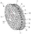
图1是本发明的外观结构示意图。FIG. 1 is a schematic diagram of the appearance structure of the present invention.
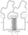
图2是图1的分解结构示意图。FIG. 2 is a schematic diagram of the exploded structure of FIG. 1 .
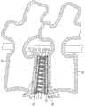
图3是图1的结构剖视示意图。FIG. 3 is a schematic cross-sectional view of the structure of FIG. 1 .
图4是本发明和脊椎骨组合的结构示意图;图中描绘了固定部嵌入脊椎骨的情形。Fig. 4 is a schematic structural diagram of the combination of the present invention and the vertebrae; the figure depicts the situation in which the fixing part is embedded in the vertebrae.
图5是本发明的一操作实施例示意图;图中显示第一假体突出物和第二假体突出物响应人体脊椎运动的结构情形。5 is a schematic diagram of an operational embodiment of the present invention; the figure shows the structural situation of the first prosthetic protrusion and the second prosthetic protrusion in response to the movement of the human spine.
附图标记说明Description of reference numerals
10第一假体10 The first prosthesis
11、21盘11, 21 discs
11a、21a第一面11a, 21a first side
11b、21b第二面11b, 21b second side
13、23微孔组织13, 23 microporous tissue
14、24固定部14, 24 Fixed part
15、25突出物15, 25 protrusions
16、26根部16, 26 roots
17、27自由端17, 27 Free end
18、28空间18, 28 space
20第二假体20 Second prosthesis
30脊椎骨30 vertebrae
m、n距离m, n distance
具体实施方式Detailed ways
请参阅图1、2及3,本发明的应力分散式人工椎间盘包括第一假体和第二假体的组合;概分别以参考编号10、20表示。第一假体10和第二假体20可分别结合在每一节相邻脊椎骨30之间的位置;例如,图4所描绘的情形。第一假体10和第二假体20分别具有一(刚性)盘11、21和设置在盘11、21上的多个突出物12、22。Please refer to FIGS. 1 , 2 and 3 , the stress-dispersed artificial intervertebral disc of the present invention includes a combination of a first prosthesis and a second prosthesis; they are indicated by
详细来说,第一假体10的盘11、第二假体20的盘21分别有第一面11a、21a和第二面11b、21b。第一面11a、21a设置有粗糙结构或微孔组织13、23和固定部14、24;固定部14、24形成圆弧轮廓的锥体结构,供嵌入脊椎骨30里面,如上述的将第一假体10和第二假体20固定在每一节相邻脊椎骨30之间的位置;微孔组织13、23提供人体组织穿越、附着生长,辅助固定部14、24,构成较佳的固定效果。In detail, the
图中也显示了第一假体10的盘第二面11b和第二假体20的盘第二面21b形成彼此相对的形态(即,第一假体10的盘第二面11b朝向第二假体20的盘第二面21b);以及,盘11、21的第二面11b、21b也设有粗糙结构或微孔组织13、23。The figure also shows that the disc
在所采较佳的实施例中,盘11、21的第二面11b、21b分别设置有垂直凸出的多个突出物15、25。每一个突出物15(或25)选择硅胶或其类似材料制成,而具有一弹性运动范围或弹性作用;包括相连接的根部16(或26),设置在盘11的第二面11b(或盘21的第二面21b)上;以及,连接根部16(或26)朝另一端突出的自由端17(或27)。突出物15(或25)的根部16(或26)宽度或直径朝自由端17(或27)递减,使突出物15(或25)形成(圆)锥体结构。In the preferred embodiment adopted, the
可了解的是,上述根部16(或26)可和盘11、21第二面11b、21b的微孔组织13、23相嵌合,达到更稳定结合的作用。It can be understood that the root portion 16 (or 26 ) can be fitted with the
请参考图1、2及3,第一假体10和第二假体20的每一突出物15、25之间分别界定出一空间18、28。第一假体突出物15和第二假体突出物25彼此交错相插,形成摩擦干涉状态。以及,使第一假体10的突出物15位在第二假体20的空间28范围内,第一假体突出物15的自由端17到第二假体突出物25的根部26,形成一距离m;第二假体20的突出物25位在第一假体10的空间18范围内,第二假体突出物25的自由端27到第一假体突出物15的根部16,形成一距离n;并且,所述空间18、28和距离m、n容许第一假体突出物15、第二假体突出物25响应人体脊椎运动而相对产生位移、弯曲运动,来抵销脊椎运动产生的应力或作用力情形。Referring to FIGS. 1 , 2 and 3 , a
在一个可行的实施例中,第一假体突出物15和第二假体突出物25的数量比例范围是1:2~1:5,形成第二假体突出物25包围第一假体突出物15的形态。In a feasible embodiment, the number ratio of the
请参阅图4、5,当第一假体10、第二假体20响应人体脊椎运动时,第一假体突出物15和第二假体突出物25会相对产生位移、弯曲运动,来负载、分散脊椎运动产生的应力或作用力。也就是说,脊椎运动产生的应力或作用力(或动能)藉第一假体突出物15和第二假体突出物25的相对位移、弯曲运动(或转换成位能),达到抵消或分散应力,使应力被尽可能的分散到每一个突出物15、25的作用,降低应力集中情形,而使应力分布更符合人体工学的作用。Please refer to FIGS. 4 and 5 , when the
代表性的来说,这应力分散式人工椎间盘在符合稳定的固定作用的条件下,包括了下列的优点和考量:Typically, this stress-distributed artificial disc includes the following advantages and considerations under the condition of stable fixation:
1.该第一假体10、第二假体20的组合结构是被重行设计考量,而使其构造不同于现有,也相异于常规应用弹簧、金属材料制成凸球体和浅凹槽结构的组合、金属盘之间应用氮化硅聚合物、二氧化硅聚合物制成一整个弹性体的结构形态。例如,第一假体10、第二假体20分别设置突出物15、25,交错相插的位在空间18、28的范围内,形成摩擦干涉形态;突出物15、25具有根部16、26和自由端17、27;第一假体突出物15的自由端17到第二假体突出物25的根部26的距离m,第二假体突出物25的自由端27到第一假体突出物15的根部16的距离n等部份,明显改变了它的使用和操作形态,而有别于现有技术。1. The combined structure of the
2.特别是,第一假体突出物15和第二假体突出物25依据位置,产生不同程度的位移、弯曲运动,来响应人体脊椎运动的情形,不仅改善普通应用略凸球体和浅凹槽结构的组合,容易因为外力或运动而发生移位或脱离的情形;并且,旧法中应用一整个弹性体结构,产生作用力、反作用力,企图回复成初始状态,而干扰人体脊椎活动的自然度、无法立即响应人体运动,而有迟缓或时间延迟、灵活度较差等情形,也被尽可能的降到最低。2. In particular, the first
Claims (9)
Translated fromChinesePriority Applications (1)
| Application Number | Priority Date | Filing Date | Title |
|---|---|---|---|
| CN201510198671.8ACN106137471B (en) | 2015-04-24 | 2015-04-24 | Stress Distributed Artificial Intervertebral Disc |
Applications Claiming Priority (1)
| Application Number | Priority Date | Filing Date | Title |
|---|---|---|---|
| CN201510198671.8ACN106137471B (en) | 2015-04-24 | 2015-04-24 | Stress Distributed Artificial Intervertebral Disc |
Publications (2)
| Publication Number | Publication Date |
|---|---|
| CN106137471A CN106137471A (en) | 2016-11-23 |
| CN106137471Btrue CN106137471B (en) | 2020-02-18 |
Family
ID=57347040
Family Applications (1)
| Application Number | Title | Priority Date | Filing Date |
|---|---|---|---|
| CN201510198671.8AExpired - Fee RelatedCN106137471B (en) | 2015-04-24 | 2015-04-24 | Stress Distributed Artificial Intervertebral Disc |
Country Status (1)
| Country | Link |
|---|---|
| CN (1) | CN106137471B (en) |
Family Cites Families (7)
| Publication number | Priority date | Publication date | Assignee | Title |
|---|---|---|---|---|
| DE602004023039D1 (en)* | 2003-07-23 | 2009-10-22 | Ebi Llc | Expandable intervertebral implant |
| US7153325B2 (en)* | 2003-08-01 | 2006-12-26 | Ultra-Kinetics, Inc. | Prosthetic intervertebral disc and methods for using the same |
| FR2876900B1 (en)* | 2004-10-22 | 2007-01-05 | Sdgi Holdings Inc | INTERVERTEBRAL IMPLANT AND DEVICE FOR STABILIZING THE RACHIS COMPRISING THE SAME |
| CH705709B1 (en)* | 2005-08-29 | 2013-05-15 | Bird Biedermann Ag | Spinal implant. |
| KR20110049771A (en)* | 2008-07-14 | 2011-05-12 | 신세스 게엠바하 | Flexible buffering intervertebral spacer device |
| FR2988995B1 (en)* | 2012-04-05 | 2015-01-09 | Fournitures Hospitalieres Ind | INTERVERTEBRAL DISC PROSTHESIS |
| EP2674133A1 (en)* | 2012-06-14 | 2013-12-18 | WALDEMAR LINK GmbH & Co. KG | Intervertebral fusion implant |
- 2015
- 2015-04-24CNCN201510198671.8Apatent/CN106137471B/ennot_activeExpired - Fee Related
Also Published As
| Publication number | Publication date |
|---|---|
| CN106137471A (en) | 2016-11-23 |
Similar Documents
| Publication | Publication Date | Title |
|---|---|---|
| KR101421684B1 (en) | Intervertebral disc prosthesis | |
| KR101041668B1 (en) | Prosthetic intervertebral discs or artificial vertebrae | |
| JP4211221B2 (en) | Intervertebral disc prosthesis with liquid chamber | |
| JP4254061B2 (en) | Intervertebral disc prosthesis with contact stud | |
| RU2010139781A (en) | PROSTHESIS OF AN INTERVERBINAL DISK WITH A STRUCTURE BASED ON A BALL AND RING | |
| JP2009508633A5 (en) | ||
| CN106726022A (en) | A kind of artificial intervertebral disk and its forming method without interface friction | |
| JP2006517436A (en) | Artificial disc | |
| US20070203580A1 (en) | Intervertebral filling | |
| WO2007094923A3 (en) | Intervertebral disc prosthesis having multiple bearing surfaces | |
| JP2002532141A (en) | Intervertebral disc prosthesis | |
| EP2201911A3 (en) | Expandable prosthetic valve having anchoring appendages | |
| JP5744319B2 (en) | Prosthetic intervertebral disc | |
| TW201110949A (en) | Displacement leaf spring and artificial intervertebral disc containing the same | |
| TWI645842B (en) | Stress-distributed artificial intervertebral disc | |
| CN106137471B (en) | Stress Distributed Artificial Intervertebral Disc | |
| US20110257747A1 (en) | Kit for constructing a spinal disk prosthesis, and system for constructing different spinal disk prostheses | |
| CN103429195B (en) | A device used to replace a damaged intervertebral disc | |
| EP3851070B1 (en) | Implant structure | |
| KR101498657B1 (en) | Artificial intervertebral disc | |
| TWM491456U (en) | Artificial intervertebral disk | |
| TWI883908B (en) | Artificial disc | |
| TWI653973B (en) | Vertebral simulation of spinal implants | |
| CN211131558U (en) | intervertebral disc prosthesis | |
| CN101828978B (en) | Displacement reed and artificial intervertebral disc with the displacement reed |
Legal Events
| Date | Code | Title | Description |
|---|---|---|---|
| C06 | Publication | ||
| PB01 | Publication | ||
| SE01 | Entry into force of request for substantive examination | ||
| SE01 | Entry into force of request for substantive examination | ||
| GR01 | Patent grant | ||
| GR01 | Patent grant | ||
| CF01 | Termination of patent right due to non-payment of annual fee | ||
| CF01 | Termination of patent right due to non-payment of annual fee | Granted publication date:20200218 Termination date:20210424 |