CN106104372B - Directional display device and directional display device - Google Patents
Directional display device and directional display deviceDownload PDFInfo
- Publication number
- CN106104372B CN106104372BCN201580015468.0ACN201580015468ACN106104372BCN 106104372 BCN106104372 BCN 106104372BCN 201580015468 ACN201580015468 ACN 201580015468ACN 106104372 BCN106104372 BCN 106104372B
- Authority
- CN
- China
- Prior art keywords
- light
- window
- pixels
- display device
- parallax
- Prior art date
- Legal status (The legal status is an assumption and is not a legal conclusion. Google has not performed a legal analysis and makes no representation as to the accuracy of the status listed.)
- Active
Links
Images


Classifications
- G—PHYSICS
- G02—OPTICS
- G02B—OPTICAL ELEMENTS, SYSTEMS OR APPARATUS
- G02B6/00—Light guides; Structural details of arrangements comprising light guides and other optical elements, e.g. couplings
- G02B6/0001—Light guides; Structural details of arrangements comprising light guides and other optical elements, e.g. couplings specially adapted for lighting devices or systems
- G02B6/0011—Light guides; Structural details of arrangements comprising light guides and other optical elements, e.g. couplings specially adapted for lighting devices or systems the light guides being planar or of plate-like form
- G02B6/0066—Light guides; Structural details of arrangements comprising light guides and other optical elements, e.g. couplings specially adapted for lighting devices or systems the light guides being planar or of plate-like form characterised by the light source being coupled to the light guide
- G02B6/0068—Arrangements of plural sources, e.g. multi-colour light sources
- G—PHYSICS
- G02—OPTICS
- G02B—OPTICAL ELEMENTS, SYSTEMS OR APPARATUS
- G02B30/00—Optical systems or apparatus for producing three-dimensional [3D] effects, e.g. stereoscopic images
- G02B30/20—Optical systems or apparatus for producing three-dimensional [3D] effects, e.g. stereoscopic images by providing first and second parallax images to an observer's left and right eyes
- G02B30/26—Optical systems or apparatus for producing three-dimensional [3D] effects, e.g. stereoscopic images by providing first and second parallax images to an observer's left and right eyes of the autostereoscopic type
- G02B30/27—Optical systems or apparatus for producing three-dimensional [3D] effects, e.g. stereoscopic images by providing first and second parallax images to an observer's left and right eyes of the autostereoscopic type involving lenticular arrays
- G02B30/28—Optical systems or apparatus for producing three-dimensional [3D] effects, e.g. stereoscopic images by providing first and second parallax images to an observer's left and right eyes of the autostereoscopic type involving lenticular arrays involving active lenticular arrays
- G—PHYSICS
- G02—OPTICS
- G02B—OPTICAL ELEMENTS, SYSTEMS OR APPARATUS
- G02B30/00—Optical systems or apparatus for producing three-dimensional [3D] effects, e.g. stereoscopic images
- G02B30/20—Optical systems or apparatus for producing three-dimensional [3D] effects, e.g. stereoscopic images by providing first and second parallax images to an observer's left and right eyes
- G02B30/26—Optical systems or apparatus for producing three-dimensional [3D] effects, e.g. stereoscopic images by providing first and second parallax images to an observer's left and right eyes of the autostereoscopic type
- G02B30/30—Optical systems or apparatus for producing three-dimensional [3D] effects, e.g. stereoscopic images by providing first and second parallax images to an observer's left and right eyes of the autostereoscopic type involving parallax barriers
- G02B30/31—Optical systems or apparatus for producing three-dimensional [3D] effects, e.g. stereoscopic images by providing first and second parallax images to an observer's left and right eyes of the autostereoscopic type involving parallax barriers involving active parallax barriers
- G—PHYSICS
- G02—OPTICS
- G02B—OPTICAL ELEMENTS, SYSTEMS OR APPARATUS
- G02B6/00—Light guides; Structural details of arrangements comprising light guides and other optical elements, e.g. couplings
- G02B6/0001—Light guides; Structural details of arrangements comprising light guides and other optical elements, e.g. couplings specially adapted for lighting devices or systems
- G02B6/0011—Light guides; Structural details of arrangements comprising light guides and other optical elements, e.g. couplings specially adapted for lighting devices or systems the light guides being planar or of plate-like form
- G02B6/0033—Means for improving the coupling-out of light from the light guide
- G02B6/0035—Means for improving the coupling-out of light from the light guide provided on the surface of the light guide or in the bulk of it
- G02B6/0045—Means for improving the coupling-out of light from the light guide provided on the surface of the light guide or in the bulk of it by shaping at least a portion of the light guide
- G02B6/0046—Tapered light guide, e.g. wedge-shaped light guide
- G02B6/0048—Tapered light guide, e.g. wedge-shaped light guide with stepwise taper
- H—ELECTRICITY
- H04—ELECTRIC COMMUNICATION TECHNIQUE
- H04N—PICTORIAL COMMUNICATION, e.g. TELEVISION
- H04N13/00—Stereoscopic video systems; Multi-view video systems; Details thereof
- H04N13/30—Image reproducers
- H04N13/366—Image reproducers using viewer tracking
Landscapes
- Physics & Mathematics (AREA)
- General Physics & Mathematics (AREA)
- Optics & Photonics (AREA)
- Engineering & Computer Science (AREA)
- Multimedia (AREA)
- Signal Processing (AREA)
- Testing, Inspecting, Measuring Of Stereoscopic Televisions And Televisions (AREA)
Abstract
Description
Translated fromChinese相关专利申请的交叉引用:本专利申请涉及并要求2014年3月21日提交的名称为“Directional backlight”(定向背光源)的共同转让的美国临时专利申请No.61/968,935(代理人参考号:371000)的优先权,其全文以引用方式并入本文。另外,本专利申请涉及:2011年11月18日提交的名称为“Directional flat illuminators”(定向扁平式照明器)的美国专利申请No.13/300,293(代理人参考号95194936.281001);2013年10月2日提交的名称为“Temporally multiplexed display with landscape and portrait operationmodes”(具有横向操作模式和纵向操作模式的时间多路复用显示器)的美国专利申请No.14/044,767 (代理人参考号95194936.339001);2013年12月20日提交的名称为“Superlens component for directional display”(用于定向显示器的超透镜组件)的美国专利申请No.14/137,569 (代理人参考号95194936.351001);2014年2月21日提交的名称为“Directional backlight” (定向背光源)的美国专利申请No.14/186,862(代理人参考号95194936.355001);以及 2013年5月17日提交的名称为“Control system for adirectional light source”(用于定向光源的控制系统)的美国专利申请No.13/897191(代理人参考号95194936.362001),这些专利申请全文均以引用方式并入本文。CROSS REFERENCE TO RELATED APPLICATIONS: This patent application relates to and claims commonly assigned U.S. Provisional Patent Application No. 61/968,935, filed March 21, 2014, entitled "Directional backlight" (Attorney Ref. : 371000), which is incorporated herein by reference in its entirety. In addition, this patent application relates to: US Patent Application No. 13/300,293 (Attorney Ref. 95194936.281001), entitled "Directional flat illuminators", filed Nov. 18, 2011; Oct. 2013 U.S. Patent Application No. 14/044,767 (Attorney Ref. 95194936.339001), filed on 2, entitled "Temporally multiplexed display with landscape and portrait operationmodes"; US Patent Application No. 14/137,569 (Attorney Ref. 95194936.351001), filed Dec. 20, 2013, entitled "Superlens component for directional display"; Feb. 21, 2014 U.S. Patent Application No. 14/186,862 (Attorney Ref. 95194936.355001) entitled "Directional backlight"; and "Control system for adirectional light source" filed on May 17, 2013 ( Control System for Directional Light Sources), US Patent Application No. 13/897191 (Attorney Ref. 95194936.362001), which are incorporated herein by reference in their entirety.
技术领域technical field
本发明整体涉及光调制装置的照明,并且更具体地讲,涉及用于从局部光源提供大面积照明的光导,以便在2D、3D和/或自动立体显示装置中使用。The present invention relates generally to the illumination of light modulation devices and, more particularly, to light guides for providing large area illumination from localized light sources for use in 2D, 3D and/or autostereoscopic display devices.
背景技术Background technique
空间多路复用自动立体显示器通常使视差组件(诸如透镜状屏幕或视差屏障)与图像阵列对准,所述图像阵列被布置成在空间光调制器(例如LCD)上的至少第一组像素和第二组像素。视差组件将来自该像素组中的每个的光导向至不同的相应方向,以在显示器前面提供第一观察窗和第二观察窗。观察者将眼睛置于第一观察窗中用来自第一组像素的光可看到第一图像;而将眼睛置于第二观察窗中用来自第二组像素的光可看到第二图像。Spatially multiplexed autostereoscopic displays typically align a parallax component, such as a lenticular screen or parallax barrier, with an image array arranged as at least a first set of pixels on a spatial light modulator (eg, LCD) and the second set of pixels. A parallax component directs light from each of the pixel groups into different respective directions to provide a first viewing window and a second viewing window in front of the display. The observer places the eye in the first viewing window to see the first image with light from the first set of pixels; and places the eye in the second viewing window to see the second image with light from the second set of pixels .
与空间光调制器的原始分辨率相比,此类显示器具有降低的空间分辨率,并且此外,观察窗的结构由像素孔形状和视差组件成像功能决定。像素之间的间隙(例如对于电极而言)通常产生不均匀的观察窗。不期望的是,当观察者相对于显示器横向移动时,此类显示器呈现图像闪烁,因此限制了显示器的观察自由度。此类闪烁可通过使光学元件散焦而减少;然而,此类散焦导致图像串扰程度加大并增加观察者的视觉疲劳。可通过调整像素孔的形状来减少此类闪烁,然而此类改变可降低显示器亮度并且可包括对空间光调制器中的电子器件进行寻址。Such displays have reduced spatial resolution compared to the native resolution of the spatial light modulator, and in addition, the structure of the viewing window is determined by the pixel aperture shape and parallax component imaging capabilities. Gaps between pixels (eg for electrodes) typically create non-uniform viewing windows. Undesirably, such displays exhibit image flickering when the viewer moves laterally relative to the display, thus limiting the viewing freedom of the display. Such flicker can be reduced by defocusing the optics; however, such defocusing results in increased levels of image crosstalk and increased visual fatigue for the observer. Such flicker can be reduced by adjusting the shape of the pixel holes, however such changes can reduce display brightness and can include addressing electronics in the spatial light modulator.
作为空间多路复用显示器替代形式,时间多路复用显示器可包括定向背光源,诸如专利申请序列13/300,293中所述,该专利申请全文以引用方式并入本文。由于背光源的波导组件排布为实现高度的空间和角度均匀性而产生了散射,此类时间多路复用显示器可产生不期望的串扰。另外,需要快速切换空间光调制器,因而增加了成本和复杂度。快速切换空间光调制器中的时间串扰还可降低图像串扰。在2D操作中,比起常规广角背光源,此类定向背光源也可实现高效照明和高亮度。可能可取的是使用定向背光源可减少自动立体显示器的串扰,同时维持在2D操作模式下高效率和高亮度的优点。As an alternative to a spatially multiplexed display, a temporally multiplexed display may include a directional backlight, such as described in patent application Ser. 13/300,293, which is incorporated herein by reference in its entirety. Such time-multiplexed displays can produce undesirable crosstalk due to the scattering created by the arrangement of the waveguide components of the backlight to achieve a high degree of spatial and angular uniformity. Additionally, fast switching of spatial light modulators is required, thus increasing cost and complexity. Temporal crosstalk in fast switching spatial light modulators can also reduce image crosstalk. In 2D operation, such directional backlights also enable efficient illumination and high brightness compared to conventional wide-angle backlights. It may be desirable to use a directional backlight to reduce autostereoscopic display crosstalk, while maintaining the advantages of high efficiency and high brightness in 2D mode of operation.
发明内容SUMMARY OF THE INVENTION
根据本公开的第一方面,一种定向显示装置可包括定向背光源,所述定向背光源包括:波导,所述波导包括用于沿所述波导引导光的相对的第一引导表面和第二引导表面,以及光源阵列,所述光源阵列被布置成在跨所述波导的横向方向上的不同输入位置处生成输入光,其中所述第二引导表面被布置成通过所述第一引导表面将被引导穿过所述波导的光偏转到所述波导外,来作为输出光,并且其中所述波导被布置成在输出方向上将所述输出光导向到光学窗中,所述输出方向分布在取决于所述输入光的所述输入位置的横向方向上;包括像素阵列的透射空间光调制器,所述像素阵列被布置成接收来自所述波导的所述输出光并且对其进行调制,以便显示图像;以及与所述空间光调制器串联的视差元件,所述视差元件被布置成将来自所述空间光调制器的像素的光导向到观察窗中。According to a first aspect of the present disclosure, a directional display device may include a directional backlight including: a waveguide including opposing first and second guiding surfaces for guiding light along the waveguide a guide surface, and an array of light sources arranged to generate input light at different input positions in a lateral direction across the waveguide, wherein the second guide surface is arranged to pass the first guide surface to Light guided through the waveguide is deflected out of the waveguide as output light, and wherein the waveguide is arranged to direct the output light into the optical window in an output direction distributed in in a lateral direction depending on the input position of the input light; a transmissive spatial light modulator comprising an array of pixels arranged to receive and modulate the output light from the waveguide so as to displaying an image; and a parallax element in series with the spatial light modulator, the parallax element being arranged to direct light from pixels of the spatial light modulator into a viewing window.
通过与视差屏障显示器比较的方式,定向背光源可提供高分辨率和较小的厚度。然而,已了解到,为实现用于显示用途的期望特性,可通过将定向背光源的光学窗输出与包括透射式空间光调制器和视差元件的空间多路复用显示器的观察窗组合来实现图像串扰的大量减少。这样的显示器针对自动立体显示用途实现较高的舒适性并使在双视图显示系统的图像之间的重影减少。By way of comparison to parallax barrier displays, directional backlights provide high resolution and reduced thickness. However, it has been understood that to achieve the desired characteristics for display applications, it can be achieved by combining the optical window output of a directional backlight with a viewing window of a spatially multiplexed display comprising transmissive spatial light modulators and parallax elements Substantial reduction in image crosstalk. Such a display achieves high comfort for autostereoscopic display applications and reduces ghosting between images of a dual view display system.
可实现高图像对比度和可见度以用于高照度环境诸如户外。对于所需的显示器亮度,针对自动立体且2D的广角操作模式,可相较于非定向背光源提供减少的显示器能耗。高空间和角度均匀性可以在广角且定向的操作模式下实现。High image contrast and visibility can be achieved for use in high light environments such as outdoors. For the required display brightness, for autostereoscopic and 2D wide-angle operating modes, this provides reduced display power consumption compared to non-directional backlights. High spatial and angular uniformity can be achieved in wide-angle and directional modes of operation.
视差元件可为视差屏障或可为透镜阵列。透镜阵列可为液晶透镜阵列。视差元件可控制来选择观察窗的位置。视差元件是液晶屏障元件阵列。视差元件可为包括屏障元件阵列的视差屏障,所述屏障元件阵列可控制来阻挡或透射光,并且由此选择所述观察窗的位置。视差元件可为渐变折射率液晶透镜阵列。包括液晶透镜阵列的定向显示装置还可包括偏振切换元件,所述偏振切换元件被布置成使所述液晶透镜阵列的至少部分在透射操作模式与透镜操作模式之间切换。The parallax element may be a parallax barrier or may be a lens array. The lens array may be a liquid crystal lens array. The parallax element can be controlled to select the position of the viewing window. The parallax element is an array of liquid crystal barrier elements. The parallax element may be a parallax barrier comprising an array of barrier elements controllable to block or transmit light, and thereby select the position of the viewing window. The parallax element may be a graded index liquid crystal lens array. A directional display device comprising a liquid crystal lens array may further comprise a polarization switching element arranged to switch at least part of the liquid crystal lens array between a transmissive mode of operation and a lens mode of operation.
可将定向背光显示器的观察窗的光学质量提供用于轴外观察位置,并可获得可切换的2D-3D操作。The optical quality of the viewing window of a directional backlit display can be provided for off-axis viewing positions and switchable 2D-3D operation is available.
由定向背光源提供的光学窗和由视差元件提供的观察窗相对彼此成非零锐角而延伸。非零锐角可为范围为从25至65度、从30至60度、从35至55度、或从40至50度的角度。The optical window provided by the directional backlight and the viewing window provided by the parallax element extend at a non-zero acute angle relative to each other. The non-zero acute angle may be an angle ranging from 25 to 65 degrees, from 30 to 60 degrees, from 35 to 55 degrees, or from 40 to 50 degrees.
可实现可在横向操作和纵向操作中提供高效自动立体操作的显示器。A display that provides efficient autostereoscopic operation in both landscape and portrait operation can be achieved.
视差元件和空间光调制器可配合以产生具有不均匀横向窗照度分布的观察窗,并且定向背光源可布置成产生具有不均匀横向窗亮度分布的光学窗并对观察窗的横向窗亮度分布的不均匀性进行补偿。The parallax element and the spatial light modulator can cooperate to produce a viewing window with a non-uniform lateral window illumination distribution, and the directional backlight can be arranged to produce an optical window with a non-uniform lateral window brightness distribution and provide a control of the viewing window's lateral window brightness distribution. to compensate for inhomogeneity.
定向背光源还可包括透射元件,所述透射元件被设置在光源上方并且具有在横向方向上变化的透射率,以便提供定向背光源产生的光学窗的不均匀横向窗亮度分布。The directional backlight may also include a transmissive element disposed above the light source and having a transmissivity that varies in the lateral direction to provide a non-uniform lateral window brightness distribution of the optical window produced by the directional backlight.
针对相对于显示器移动的观察者的显示闪烁可减少,同时达到期望图像串扰水平。Display flicker for a viewer moving relative to the display can be reduced while achieving a desired level of image crosstalk.
所述第一引导表面可被布置成通过全内反射来引导光,并且所述第二引导表面可包括多个光提取特征和中间区域,所述多个光提取特征被取向为在允许作为所述输出光穿过所述第一引导表面离开的方向上导向被引导穿过所述波导的光,所述中间区域位于所述光提取特征之间并且被布置用于引导光穿过所述波导。所述第二引导表面可具有阶梯形状,所述阶梯形状包括作为所述光提取特征的小平面以及中间区域。定向背光源还可包括后反射器,所述后反射器包括反射小平面的线性阵列,其中反射小平面被布置成使来自光源的透射穿过波导的多个小平面的光反射回穿过所述波导,以离开穿过第一引导表面进入所述光学窗。光提取特征在波导的横向方向上可具有正光焦度。The first guide surface may be arranged to guide light by total internal reflection, and the second guide surface may include a plurality of light extraction features and an intermediate region, the plurality of light extraction features oriented to allow as all the output light is directed to light guided through the waveguide in a direction in which the output light exits through the first guide surface, the intermediate region is located between the light extraction features and is arranged to guide light through the waveguide . The second guide surface may have a stepped shape including a facet as the light extraction feature and an intermediate region. The directional backlight may also include a back reflector comprising a linear array of reflective facets, wherein the reflective facets are arranged to reflect light from the light source transmitted through the plurality of facets of the waveguide back through all facets. the waveguide to exit through the first guide surface into the optical window. The light extraction features may have a positive optical power in the lateral direction of the waveguide.
所述第一引导表面可被布置成通过全内反射来引导光,并且所述第二引导表面可为基本上平坦的并以一定角度倾斜,以在破坏所述全内反射的多个方向上导向光以用于通过所述第一引导表面输出光,并且所述显示装置还可包括跨所述波导的所述第一引导表面延伸的偏转元件以用于使光朝所述第一引导表面的法线偏转。波导还可包括反射端,用于将输入光反射回穿过波导,第二引导表面被布置成在从反射端反射后,将光作为输出光偏转穿过第一引导表面。反射端在波导的横向方向上可具有正光焦度。The first guide surface may be arranged to guide light by total internal reflection, and the second guide surface may be substantially flat and inclined at an angle to disrupt the total internal reflection in directions that disrupt the total internal reflection directing light for outputting light through the first guide surface, and the display device may further include a deflection element extending across the first guide surface of the waveguide for directing light toward the first guide surface normal deflection. The waveguide may further comprise a reflective end for reflecting the input light back through the waveguide, the second guide surface being arranged to deflect the light as output light through the first guide surface after reflection from the reflective end. The reflective end may have a positive optical power in the lateral direction of the waveguide.
根据本公开的第二方面,提供一种定向显示设备,所述定向显示设备包括:根据前述权利要求中任一项所述的定向显示装置;以及控制系统,所述控制系统被布置成控制光源将光导向到光学窗中,以供观察者观察。控制系统还可被布置成控制空间光调制器。定向显示设备可为自动立体显示设备,其中:视差元件可被布置成将光从第一组空间多路复用像素和第二组空间多路复用像素导向到左眼观察窗和右眼观察窗中,以供观察者的左眼和右眼观察;控制系统可被布置成控制空间光调制器在第一组空间多路复用像素和第二组空间多路复用像素上显示左眼图像和右眼图像;并且控制系统可被布置成控制光源将光导向到光学窗中,以供观察者的左眼和右眼两者观察。According to a second aspect of the present disclosure, there is provided a directional display device comprising: a directional display device according to any preceding claim; and a control system arranged to control a light source Direct light into an optical window for viewing by an observer. The control system may also be arranged to control the spatial light modulator. The directional display device may be an autostereoscopic display device, wherein: the parallax element may be arranged to direct light from the first set of spatially multiplexed pixels and the second set of spatially multiplexed pixels to left eye viewing windows and right eye viewing windows for viewing by the left and right eyes of the observer; the control system may be arranged to control the spatial light modulator to display the left eye on the first set of spatially multiplexed pixels and the second set of spatially multiplexed pixels image and a right eye image; and the control system may be arranged to control the light source to direct light into the optical window for viewing by both the left and right eyes of the observer.
有利地,定向背光源可向空间光调制器和视差元件提供照明,使得相应的光学窗和观察窗可布置成进行配合,从而改进串扰特性。反视立体区可减小或消除,并且串扰减少。Advantageously, the directional backlight can provide illumination to the spatial light modulator and parallax element so that the corresponding optical windows and viewing windows can be arranged to cooperate to improve crosstalk characteristics. Anti-stereoscopic regions can be reduced or eliminated, and crosstalk is reduced.
视差元件可控制来选择观察窗的位置,并且控制系统还可被布置成控制视差元件将光导向到左观察窗和右观察窗中。The parallax element is controllable to select the position of the viewing windows, and the control system can also be arranged to control the parallax element to direct light into the left and right viewing windows.
有利地,相比与仅包括定向背光源的时间多路复用显示器,可向正在移动的观察者提供范围更广的观察位置。Advantageously, a moving observer can be provided with a wider range of viewing positions than a time-multiplexed display that includes only a directional backlight.
视差元件可控制来选择观察窗的位置;控制系统可布置成以时间多路复用的方式控制所述视差元件:(a)将光从第一组空间多路复用像素和第二组空间多路复用像素导向到左眼观察窗和右眼观察窗中,以供所述观察者的左眼和右眼观察,以及(b)将光从第一组像素和第二组像素导向到反向的右眼观察窗和左眼观察窗中,以供所述观察者的右眼和左眼观察,所述控制系统可布置成以与控制视差元件同步地、以时间多路复用的方式控制空间光调制器:(a)当来自第一组空间多路复用像素和第二组空间多路复用像素的光导向到左眼观察窗和右眼观察窗中时,分别在第一组空间多路复用像素和第二组空间多路复用像素上显示左眼图像和右眼图像,以及(b)当来自第一组空间多路复用像素和第二组空间多路复用像素的光导向到反向的右眼观察窗和左眼观察窗中时,分别在第一组空间多路复用像素和第二组空间多路复用像素上显示右眼图像和左眼图像;并且控制系统可被布置成控制光源将光导向到光学窗中,以供观察者的双眼观察。The parallax element is controllable to select the position of the viewing window; the control system may be arranged to control the parallax element in a time-multiplexed manner: (a) spatially multiplexing light from a first set of pixels and a second set of spatially multiplexed pixels The multiplexed pixels are directed into left and right eye viewing windows for viewing by the observer's left and right eyes, and (b) directing light from the first and second sets of pixels to In opposite right-eye viewing windows and left-eye viewing windows for viewing by the observer's right and left eyes, the control system may be arranged to be time-multiplexed in synchronization with the control parallax element The spatial light modulator is controlled in such a way that: (a) when light from the first set of spatially multiplexed pixels and the second set of spatially multiplexed pixels is directed into the left-eye and right-eye viewing windows, respectively, Left-eye and right-eye images are displayed on one set of spatially multiplexed pixels and the second set of spatially multiplexed pixels, and (b) when images from the first set of spatially multiplexed pixels and the second set of spatially multiplexed pixels When the light from the multiplexed pixels is directed into the opposite right-eye and left-eye viewing windows, the right-eye image and the left-eye image are displayed on the first set of spatially multiplexed pixels and the second set of spatially multiplexed pixels, respectively. and the control system may be arranged to control the light source to direct light into the optical window for viewing by both eyes of the observer.
有利地,自动立体图像分辨率可增加,并且反视立体区可减小或消除。Advantageously, autostereoscopic image resolution can be increased, and anti-stereoscopic regions can be reduced or eliminated.
视差元件可被布置成将光从第一组空间多路复用像素和第二组空间多路复用像素导向到左眼观察窗和右眼观察窗中,以供观察者的左眼和右眼观察;控制系统可被布置成控制光源,将光以时间多路复用的方式导向到左眼光学窗和右眼光学窗中,以供观察者的左眼和右眼两者观察;并且控制系统可布置成与控制光源同步地、以时间多路复用的方式控制所述空间光调制器:(a)当光源将光导向到左眼光学窗中时,分别在第一组像素和第二组像素上显示左眼图像和空白图像,并且(b)当光源将光导向到右眼光学窗中时,分别在第一组像素和第二组像素上显示空白图像和右眼图像。The parallax element may be arranged to direct light from the first set of spatially multiplexed pixels and the second set of spatially multiplexed pixels into left eye viewing windows and right eye viewing windows for the left and right eyes of an observer eye observation; the control system may be arranged to control the light source to direct light in a time-multiplexed manner into the left eye optical window and the right eye optical window for observation by both the left and right eyes of an observer; and The control system may be arranged to control the spatial light modulator in a time-multiplexed manner synchronously with the control light source: (a) when the light source directs light into the left eye optical window, at the first set of pixels and A left eye image and a blank image are displayed on the second set of pixels, and (b) when the light source directs light into the right eye optical window, the blank and right eye images are displayed on the first and second sets of pixels, respectively.
有利地,来自时间多路复用显示器的串扰可进一步减少。Advantageously, crosstalk from time-multiplexed displays can be further reduced.
视差元件可控制来选择观察窗的位置,并且控制系统还可被布置成控制视差元件将光导向到左观察窗和右观察窗中。The parallax element is controllable to select the position of the viewing windows, and the control system can also be arranged to control the parallax element to direct light into the left and right viewing windows.
视差元件可控制来选择观察窗的位置;其中控制系统可布置成以时间多路复用的方式控制视差元件:(i)分别将光从第一组空间多路复用像素和第二组空间多路复用像素导向到左眼观察窗和右眼观察窗中,以供观察者的左眼和右眼观察,以及(ii)分别将光从第一组空间多路复用像素和第二组空间多路复用像素导向到右眼观察窗和左眼观察窗中,以供观察者的右眼和左眼观察;控制系统可布置成控制光源:(i)当视差元件将光从第一组像素导向到左眼观察窗并从第二组像素导向到右眼光学窗中时,以时间多路复用的方式将光导向到左眼光学窗和右眼光学窗中,以供观察者的左眼和右眼观察,并且(ii)另外当视差元件将光从第一组像素导向到右眼光学窗并从第二组像素导向到左眼光学窗中时,以时间多路复用的方式将光导向到左眼光学窗和右眼光学窗中,以供观察者的左眼和右眼观察;并且控制系统可布置成控制空间光调制器:(i)当视差元件将光从第一组像素导向到左眼观察窗中并从第二组像素导向到右眼观察窗中时,与控制光源同步地、以时间多路复用的方式:(a) 当光源将光导向到左眼光学窗中时,分别在第一组像素和第二组像素上显示左眼图像和空白图像,并且(b)在光源将光导向到右眼光学窗中时,分别在第一组像素和第二组像素上显示空白图像和右眼图像,并且(ii)当视差元件将光从第一组像素导向到右眼观察窗并从第二组像素导向到左眼观察窗中时,与控制光源同步地、以时间多路复用的方式:(a)当光源将光导向到左眼光学窗中时,分别在第一组像素和第二组像素上显示空白图像和左眼图像,并且(b)当光源将光导向到右眼光学窗中时,分别在第一组像素和第二组像素上显示右眼图像和空白图像。The parallax element is controllable to select the position of the viewing window; wherein the control system may be arranged to control the parallax element in a time-multiplexed manner: (i) to separate light from the first set of spatially multiplexed pixels and the second set of spatially multiplexed pixels, respectively The multiplexed pixels are directed into the left and right eye viewing windows for viewing by the observer's left and right eyes, and (ii) the light from the first set of spatially multiplexed pixels and the second set of spatially multiplexed pixels, respectively Groups of spatially multiplexed pixels are directed into right and left eye viewing windows for viewing by the observer's right and left eyes; the control system may be arranged to control the light source: (i) when the parallax element directs light from the first When one set of pixels is directed into the left eye viewing window and from the second set of pixels into the right eye optical window, light is directed into the left and right eye optical windows in a time-multiplexed manner for observation and (ii) additionally when the parallax element directs light from the first set of pixels into the right eye optical window and from the second set of pixels into the left eye optical window, multiplexing in time directs light into the left and right eye optical windows for viewing by the left and right eyes of an observer; and the control system may be arranged to control the spatial light modulator: (i) when the parallax element directs the light When directed from the first set of pixels into the left eye viewing window and from the second set of pixels into the right eye viewing window, in synchronization with the control light source, in a time-multiplexed manner: (a) when the light source directs the light into the left eye optical window, display a left eye image and a blank image on the first and second sets of pixels, respectively, and (b) when the light source directs light into the right eye optical window, on the first set of pixels, respectively a blank image and a right eye image are displayed on the pixels and the second set of pixels, and (ii) when the parallax element directs light from the first set of pixels into the right eye viewing window and from the second set of pixels into the left eye viewing window, Synchronously with the control light source, in a time-multiplexed manner: (a) when the light source directs light into the left eye optical window, display a blank image and a left eye image on the first and second sets of pixels, respectively , and (b) a right eye image and a blank image are displayed on the first and second sets of pixels, respectively, when the light source directs light into the right eye optical window.
有利地,串扰减少,并且自动立体图像分辨率可与空间光调制器相同。Advantageously, crosstalk is reduced and the autostereoscopic image resolution can be the same as the spatial light modulator.
视差元件可控制来选择观察窗的位置;控制系统可布置成以时间多路复用的方式控制设备视差元件:(i)将光从与第二组像素空间多路复用的第一组像素导向到左眼观察窗中,以供观察者的左眼观察,以及(ii)将光从第一组像素导向到右眼观察窗中,以供观察者的右眼观察;控制系统可布置成与控制视差元件同步地、以时间多路复用的方式控制光源:(i) 当视差元件将光从第一组像素导向到左眼观察窗中时,将光导向到左眼光学窗中,以供观察者的左眼观察,并且(ii)当视差元件将光从第一组像素导向到右眼观察窗中时,将光导向到右眼光学窗中,以供观察者的右眼观察;并且控制系统可布置成与控制视差元件同步地、以时间多路复用的方式控制空间光调制器:(i)当视差元件将光从第一组像素导向到左眼观察窗中时,分别在第一组像素和第二组像素上显示左眼图像和空白图像,并且(ii)当视差元件将光从第一组像素导向到右眼观察窗中时,分别在第一组像素和第二组像素上显示右眼图像和空白图像。The parallax element is controllable to select the position of the viewing window; the control system may be arranged to control the device parallax element in a time-multiplexed manner: (i) to spatially multiplex light from a first set of pixels with a second set of pixels directing into the left eye viewing window for viewing by the observer's left eye, and (ii) directing light from the first set of pixels into the right eye viewing window for viewing by the observer's right eye; the control system may be arranged to Controlling the light source in a time-multiplexed manner in synchronization with controlling the parallax element: (i) when the parallax element directs light from the first set of pixels into the left eye viewing window, directs light into the left eye optical window, for viewing by the observer's left eye, and (ii) when the parallax element directs light from the first set of pixels into the right eye viewing window, directs light into the right eye optical window for viewing by the observer's right eye and the control system may be arranged to control the spatial light modulator in a time-multiplexed manner in synchronization with controlling the parallax element: (i) when the parallax element directs light from the first set of pixels into the left eye viewing window, The left eye image and the blank image are displayed on the first set of pixels and the second set of pixels, respectively, and (ii) when the parallax element directs light from the first set of pixels into the right eye viewing window, on the first set of pixels and The right eye image and the blank image are displayed on the second set of pixels.
有利地,由面板切换特性造成的串扰可进一步减少。Advantageously, crosstalk caused by panel switching characteristics can be further reduced.
视差元件可控制来选择观察窗的位置,控制系统可被布置成以时间上多路复用的方式控制视差元件:(a)将光从所有像素导向到左眼观察窗中,以供观察者的左眼观察;并且(b) 将光从所有像素导向到右眼观察窗中,以供观察者的右眼观察。控制系统可布置成与控制视差元件同步地、以时间多路复用的方式控制光源以将光导向到左眼光学窗和右眼光学窗中,以供观察者的左眼和右眼观察;并且控制系统可布置成以与控制视差元件和光源同步地、以时间多路复用的方式控制空间光调制器:(a)当视差元件将光导向到左眼观察窗中时,在所有像素上显示左眼图像,并且(b)当视差元件将光导向到右眼光学窗中时,在所有像素上显示右眼图像。The parallax element can be controlled to select the position of the viewing window, and the control system can be arranged to control the parallax element in a time-multiplexed manner: (a) direct light from all pixels into the left eye viewing window for the observer and (b) direct light from all pixels into the right eye viewing window for viewing by the observer's right eye. The control system may be arranged to control the light source in a time-multiplexed manner in synchronization with the control of the parallax element to direct light into the left and right eye optical windows for viewing by the left and right eyes of an observer; And the control system may be arranged to control the spatial light modulator in a time-multiplexed manner in synchronization with controlling the parallax element and the light source: (a) when the parallax element directs light into the left eye viewing window, at all pixels The left eye image is displayed on and (b) the right eye image is displayed on all pixels when the parallax element directs light into the right eye optical window.
有利地,自动立体图像的分辨率可与空间光调制器相同,串扰减少,并且时间多路复用空间光调制器可布置成在两倍自动立体图像帧率下操作。Advantageously, the resolution of the autostereoscopic image can be the same as the spatial light modulator, crosstalk is reduced, and the time multiplexed spatial light modulator can be arranged to operate at twice the autostereoscopic image frame rate.
因此,可控制背光源、视差元件和空间光调制器,在各种期望的自动立体显示特性之间切换以匹配观察者显示器使用。Thus, the backlight, parallax element and spatial light modulator can be controlled to switch between various desired autostereoscopic display characteristics to match the viewer display usage.
定向显示设备还可包括传感器系统,传感器系统被布置成检测观察者头部的位置,控制系统被布置成根据检测到的观察者头部的位置来控制光源。The directional display device may further comprise a sensor system arranged to detect the position of the viewer's head and the control system arranged to control the light source according to the detected position of the viewer's head.
定向显示设备还可包括传感器系统,传感器系统被布置成检测观察者头部的位置,控制系统被布置成根据检测到的观察者头部的位置来控制光源和视差元件。The directional display device may further comprise a sensor system arranged to detect the position of the viewer's head and the control system arranged to control the light source and the parallax element according to the detected position of the viewer's head.
本文的实施例可提供具有大面积和薄型结构的自动立体显示器。另外,如将描述,本发明的波导可实现具有较大后工作距离的薄型光学组件。此类组件可用于定向背光源中,以提供包括自动立体显示器的定向显示器。另外,实施例可提供用于高效自动立体显示器的受控照明器,和高效2D显示器、高亮度2D显示器或实现了防窥功能的2D显示器。Embodiments herein may provide autostereoscopic displays with large areas and thin structures. Additionally, as will be described, the waveguides of the present invention enable thin optical assemblies with large back working distances. Such assemblies can be used in directional backlights to provide directional displays including autostereoscopic displays. Additionally, embodiments may provide controlled illuminators for high-efficiency autostereoscopic displays, and high-efficiency 2D displays, high-brightness 2D displays, or 2D displays that implement privacy functions.
本发明的实施例可用于多种光学系统中。实施例可包括或利用各种投影仪、投影系统、光学组件、显示器、微型显示器、计算机系统、处理器、独立成套的投影仪系统、视觉和/或视听系统以及电和/或光学装置。实际上,本发明的方面可以跟与光学和电气装置、光学系统、演示系统有关的任何设备,或者可包括任何类型的光学系统的任何设备一起使用。因此,本发明的实施例可用于光学系统、视觉和/或光学演示中使用的装置、视觉外围设备等,并且可用于多种计算环境。Embodiments of the present invention may be used in a variety of optical systems. Embodiments may include or utilize various projectors, projection systems, optical assemblies, displays, microdisplays, computer systems, processors, stand-alone projector systems, visual and/or audiovisual systems, and electrical and/or optical devices. Indeed, aspects of the present invention may be used with any apparatus related to optical and electrical devices, optical systems, presentation systems, or any apparatus that may include any type of optical system. Accordingly, embodiments of the present invention may be used in optical systems, devices used in visual and/or optical presentations, visual peripherals, etc., and in a variety of computing environments.
在详细讨论所公开的实施例之前,应当理解,本发明并不将其应用或形成限于所示的具体布置的细节,因为本发明能够采用其他实施例。此外,可以不同的组合和布置来阐述本发明的各个方面,以限定实施例在其本身权利内的独特性。另外,本文使用的术语是为了说明的目的,而非限制。Before the disclosed embodiments are discussed in detail, it is to be understood that the invention is not limited in its application or formation to the details of the specific arrangements shown, for the invention is capable of other embodiments. Furthermore, various aspects of the invention may be described in various combinations and arrangements to define the uniqueness of the embodiments within their own rights. Also, the terminology used herein is for the purpose of description and not limitation.
定向背光源通常通过调制布置在光学波导的输入孔侧的独立LED光源,来提供对从基本上整个输出表面发出的照明的控制。控制发射光定向分布可实现安全功能的单人观察,其中显示器可主要或仅被单个观察者从有限角度范围看到;可实现高电效率,其中可在小角度定向分布内提供照明;可实现对时序立体显示器和自动立体显示器的左右眼交替观察;以及可实现低成本。Directional backlights typically provide control of the illumination emanating from substantially the entire output surface by modulating individual LED light sources disposed on the input aperture side of the optical waveguide. Controlling the directional distribution of emitted light enables single-person viewing for safety functions, where the display can be seen primarily or only by a single observer from a limited range of angles; enables high electrical efficiency, where illumination can be provided within a small angular directional distribution; enables Alternate left and right eye viewing for sequential stereoscopic displays and autostereoscopic displays; and low cost.
本领域的普通技术人员在阅读本发明内容全文后,本发明的这些和其他优点以及特征将变得显而易见。These and other advantages and features of the present invention will become apparent to those of ordinary skill in the art upon reading this disclosure in its entirety.
附图说明Description of drawings
实施例通过举例的方式在附图中示出,其中类似的附图标号表示类似的组件,并且其中:Embodiments are shown by way of example in the drawings, wherein like reference numerals refer to like components, and wherein:
图1A是根据本发明的示意图,其示出了定向显示装置的一个实施例中的光传播的正视图;Figure 1A is a schematic diagram showing a front view of light propagation in one embodiment of a directional display device in accordance with the present invention;
图1B是根据本发明的示意图,其示出了图1A的定向显示装置的一个实施例中的光传播的侧视图;FIG. 1B is a schematic diagram showing a side view of light propagation in one embodiment of the directional display device of FIG. 1A in accordance with the present invention;
图2A是根据本发明的示意图,其以定向显示装置的另一个实施例中的光传播的顶视图示出;Figure 2A is a schematic diagram in accordance with the present invention showing a top view of light propagation in another embodiment of a directional display device;
图2B是根据本发明的示意图,其以图2A的定向显示装置的正视图示出了光传播;Figure 2B is a schematic diagram showing light propagation in a front view of the directional display device of Figure 2A in accordance with the present invention;
图2C是根据本发明的示意图,其以图2A的定向显示装置的侧视图示出了光传播;Figure 2C is a schematic diagram showing light propagation in a side view of the directional display device of Figure 2A in accordance with the present invention;
图3是根据本发明的示意图,其以定向显示装置的侧视图示出;Figure 3 is a schematic diagram in accordance with the present invention, shown in a side view of a directional display device;
图4A是根据本发明的示意图,其以正视图示出了定向显示装置中观察窗的生成,并且包括弯曲光提取特征;4A is a schematic diagram showing, in front view, the creation of a viewing window in a directional display device, and including curved light extraction features, in accordance with the present invention;
图4B是根据本发明的示意图,其以正视图示出了定向显示装置中第一观察窗和第二观察窗的生成,并且包括弯曲光提取特征;4B is a schematic diagram showing, in front view, the creation of a first viewing window and a second viewing window in a directional display device, and including curved light extraction features, in accordance with the present invention;
图5是根据本发明的示意图,其示出了定向显示装置中第一观察窗的生成,并且包括线性光提取特征;5 is a schematic diagram showing the generation of a first viewing window in a directional display device and including a linear light extraction feature in accordance with the present invention;
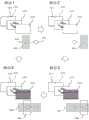
图6A是根据本发明的示意图,其示出了时间多路复用定向显示装置中的第一观察窗的生成的一个实施例;6A is a schematic diagram illustrating one embodiment of the generation of a first viewing window in a time-multiplexed directional display device in accordance with the present invention;
图6B是根据本发明的示意图,其示出了在第二时隙中时间多路复用定向显示装置中的第二观察窗的生成的另一个实施例;6B is a schematic diagram illustrating another embodiment of the generation of a second viewing window in a time-multiplexed directional display device in a second time slot in accordance with the present invention;
图6C是根据本发明的示意图,其示出了在时间多路复用定向显示装置中的第一观察窗和第二观察窗的生成的另一个实施例;6C is a schematic diagram illustrating another embodiment of the generation of a first viewing window and a second viewing window in a time-multiplexed directional display device in accordance with the present invention;
图7是根据本发明的示意图,其示出了观察者跟踪自动立体定向显示装置;Figure 7 is a schematic diagram showing an observer tracking autostereotaxic display device according to the present invention;
图8是根据本发明的示意图,其示出了多观察者定向显示装置;FIG. 8 is a schematic diagram showing a multi-viewer directional display device according to the present invention;
图9是根据本发明的示意图,其示出了防窥定向显示装置;FIG. 9 is a schematic diagram showing a privacy-proof directional display device according to the present invention;
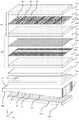
图10是根据本发明的示意图,其以侧视图示出了定向显示装置的结构;Figure 10 is a schematic diagram showing the structure of a directional display device in side view according to the present invention;
图11A是根据本发明的示意图,其以侧视图示出了包括阶梯式波导的定向显示装置的结构;11A is a schematic diagram showing, in side view, the structure of a directional display device including a stepped waveguide, according to the present invention;
图11B是根据本发明的示意图,其以侧视图示出了包括楔型波导的定向显示装置的结构;FIG. 11B is a schematic diagram showing, in side view, the structure of a directional display device including a wedge-shaped waveguide in accordance with the present invention;
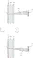
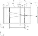
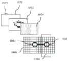
图12A是根据本发明的示意图,其以透视图示出了包括布置有空间光调制器的成像波导的定向显示装置的结构;12A is a schematic diagram showing, in perspective, the structure of a directional display device including an imaging waveguide arranged with a spatial light modulator;
图12B是根据本发明的示意图,其以透视图示出了包括布置有空间光调制器和对齐的后视差元件的成像波导的定向显示装置的结构;12B is a schematic diagram showing, in perspective, the structure of a directional display device including an imaging waveguide arranged with a spatial light modulator and an aligned rear parallax element;
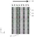
图13A是根据本发明的示意图,其以俯视图示出了定向显示装置的包括空间光调制器和对齐的后视差元件的部分的结构;13A is a schematic diagram showing, in a top view, the structure of a portion of a directional display device including a spatial light modulator and an aligned rear parallax element in accordance with the present invention;
图13B是根据本发明的示意图,其以正视图示出了图13A的光学堆叠中的偏振方向的对齐;Figure 13B is a schematic diagram showing, in front view, the alignment of polarization directions in the optical stack of Figure 13A;
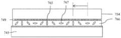
图14是根据本发明开的示意图,其以俯视图示出了定向显示装置的包括空间光调制器和对齐的后视差元件的部分的结构,该后视差元件还包括单元内偏振器;14 is a schematic diagram in accordance with the present invention showing, in a top view, the structure of a portion of a directional display device that includes a spatial light modulator and an aligned rear parallax element that also includes an in-cell polarizer;
图15A-15B是根据本发明的示意图,其以俯视图示出了定向显示装置的包括空间光调制器和对齐的后视差元件的部分的结构,该后视差元件还包括单元内偏振器;15A-15B are schematic diagrams showing, in top view, the structure of a portion of a directional display device that includes a spatial light modulator and an aligned rear parallax element that further includes an in-cell polarizer;
图16A-16B是根据本发明的示意图,其以正视图示出了包括时隙区域的视差屏障的结构;16A-16B are schematic diagrams showing, in front view, the structure of a parallax barrier including time slot regions, in accordance with the present invention;
图17A-17E是根据本发明的示意图,其以正视图示出了包括时隙区域的视差屏障的结构;17A-17E are schematic diagrams showing, in front view, the structure of a parallax barrier including time slot regions, in accordance with the present invention;
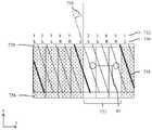
图18是根据本发明的示意图,其以透视图示出了包括布置有空间光调制器和对齐的前视差元件的成像波导的定向显示装置的结构;18 is a schematic diagram showing, in perspective, the structure of a directional display device including an imaging waveguide arranged with a spatial light modulator and an aligned front parallax element;
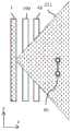
图19A是根据本发明的示意图,其以正视图示出了包括被灰度寻址的缝隙区域的视差屏障的结构;19A is a schematic diagram showing, in front view, the structure of a parallax barrier including a grayscale-addressed slit region, in accordance with the present invention;
图19B至图19C是根据本发明的示意图,其以正视图示出了包括缝隙区域的视差屏障的结构,这些缝隙区域被布置成在横向方向上有增加的横向范围;19B-19C are schematic diagrams showing, in front view, a structure of a parallax barrier including slit regions arranged to have an increased lateral extent in the lateral direction, according to the present invention;
图20是根据本发明的示意图,其以俯视图示出了包括间隙切换时隙区域的可切换视差屏障的结构;20 is a schematic diagram showing, in a top view, the structure of a switchable parallax barrier including a gap switching slot region in accordance with the present invention;
图21是根据本发明的示意图,其以俯视图示出了包括边缘场切换时隙区域的可切换视差屏障的结构;21 is a schematic diagram showing, in a top view, the structure of a switchable parallax barrier including fringe field switching slot regions, according to the present invention;
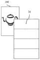
图22是根据本发明的示意图,其以透视正视图示出了在图12B的可切换自动立体显示器的纵向模式中的光学窗的布置;Figure 22 is a schematic diagram showing, in a perspective front view, the arrangement of optical windows in the portrait mode of the switchable autostereoscopic display of Figure 12B;
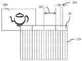
图23A至图23C是根据本发明的示意图,其以透视正视图示出了在图12B的可切换自动立体显示器的横向模式中的光学窗的布置;23A-23C are schematic diagrams showing, in perspective front view, the arrangement of optical windows in the landscape mode of the switchable autostereoscopic display of FIG. 12B in accordance with the present invention;
图24A至图24B是根据本发明的示意图,其以俯视图示出了图12B的可切换显示器的2D观察窗的布置,其中视差元件完全透射;24A-24B are schematic diagrams showing, in top view, the arrangement of the 2D viewing window of the switchable display of FIG. 12B with the parallax element fully transmissive, in accordance with the present invention;
图24C是根据本发明的示意图,其示出了图24A的布置的观察窗曲线;Fig. 24C is a schematic diagram showing a viewing window curve for the arrangement of Fig. 24A in accordance with the present invention;
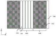
图25A是根据本发明的示意图,其以正视图示出了用于双视图空间多路复用的空间光调制器和对齐的视差屏障的布置;25A is a schematic diagram showing, in front view, an arrangement of spatial light modulators and aligned parallax barriers for dual-view spatial multiplexing;
图25B是根据本发明的示意图,其以正视图示出了用于四视图空间多路复用的空间光调制器和对齐的视差屏障的布置;25B is a schematic diagram showing, in front view, an arrangement of spatial light modulators and aligned parallax barriers for four-view spatial multiplexing;
图25C是根据本发明的示意图,其以俯视图示出了用于双视图空间多路复用的空间光调制器和对齐的视差屏障的角输出;25C is a schematic diagram showing, in a top view, the angular output of a spatial light modulator and aligned parallax barrier for dual view spatial multiplexing in accordance with the present invention;
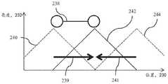
图25D是根据本发明的示意图,其示出了在图25A的布置方式中,窗平面中的光学窗亮度与位置的变化关系;Figure 25D is a schematic diagram according to the present invention showing the optical window brightness versus position in the window plane in the arrangement of Figure 25A;
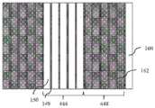
图26A是根据本发明的示意图,其以俯视图示出了用于双视图空间多路复用的定向照明与空间光调制器和对齐的视差屏障的组合的角输出;26A is a schematic diagram showing, in a top view, the angular output of a combination of directional illumination for dual view spatial multiplexing with a spatial light modulator and an aligned parallax barrier in accordance with the present invention;
图26B是根据本发明的示意图,其示出了在图26A的布置方式中,窗平面中的光学窗亮度与位置的变化关系;Figure 26B is a schematic diagram according to the present invention showing the optical window brightness versus position in the window plane in the arrangement of Figure 26A;
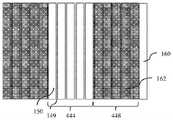
图27A是根据本发明的示意图,其以俯视图示出了用于双视图空间多路复用和时间视图多路复用的定向照明与空间光调制器和对齐的视差屏障的组合的角输出;27A is a schematic diagram showing, in top view, the angular output of directional illumination for dual-view spatial multiplexing and temporal view multiplexing in combination with spatial light modulators and aligned parallax barriers, in accordance with the present invention;
图27B是根据本公开的示意图,其以正视图示出了用于双视图空间多路复用和时间视图多路复用的空间光调制器和对齐的视差屏障的布置;27B is a schematic diagram showing, in front view, an arrangement of spatial light modulators and aligned parallax barriers for dual-view spatial multiplexing and temporal view multiplexing;
图27C-27E是根据本公开的示意图,其以俯视图示出了用于多个观察者的空间光调制器和对齐的视差屏障的布置;27C-27E are schematic diagrams showing, in top view, arrangements of spatial light modulators and aligned parallax barriers for multiple observers in accordance with the present disclosure;
图28是根据本发明的示意图,其以俯视图示出了用于具有观察者跟踪的双视图空间多路复用的定向照明与空间光调制器和对齐的视差屏障的组合的角输出;28 is a schematic diagram showing, in a top view, the angular output for a combination of a spatial light modulator and an aligned parallax barrier for dual-view spatially multiplexed directional illumination with observer tracking;
图29A是根据本发明的示意图,其以正视图示出了用于具有观察者跟踪的双视图空间多路复用的空间光调制器和对齐的视差屏障的布置;29A is a schematic diagram showing, in front view, an arrangement of spatial light modulators and aligned parallax barriers for dual-view spatial multiplexing with observer tracking;
图29B是根据本发明的示意图,其以正视图示出了用于四视图空间多路复用的空间光调制器和对齐的视差屏障的布置;29B is a schematic diagram showing, in front view, an arrangement of spatial light modulators and aligned parallax barriers for four-view spatial multiplexing;
图30是根据本发明的示意图,其示出了在用于图29A的布置方式中,窗平面中的光学窗亮度与位置的变化关系;Figure 30 is a schematic diagram according to the present invention showing optical window brightness versus position in the window plane in the arrangement used in Figure 29A;
图31是根据本发明的示意图,其示出了在具有减小的缝隙宽度的布置方式中,窗平面中的总观察窗亮度与位置的变化关系;Figure 31 is a schematic diagram showing total viewing window brightness versus position in the window plane in an arrangement with a reduced slit width;
图32是根据本发明的示意图,其示出了在用于图29A的布置方式中,窗平面中的总观察窗亮度与位置的变化关系,该布置方式还包括补偿亮度分布;Figure 32 is a schematic diagram showing the overall viewing window brightness versus position in the window plane in the arrangement used in Figure 29A, the arrangement further comprising compensating the brightness distribution;
图33A-33B是根据本发明的示意图,其以侧视图和正视图示出了包括补偿特征的LED 阵列;33A-33B are schematic diagrams showing an LED array including compensation features in side and front views in accordance with the present invention;
图34是根据本发明的示意图,其示出了在图33A的LED阵列上,补偿特征透射与位置的变化关系;FIG. 34 is a schematic diagram illustrating compensation feature transmission versus position on the LED array of FIG. 33A in accordance with the present invention;
图35是根据本发明的示意图,其示出了在用于图33A-33B的布置方式中,窗平面中的亮度与位置的变化关系;Fig. 35 is a schematic diagram showing the variation of luminance in the window plane as a function of position in the arrangement used in Figs. 33A-33B in accordance with the present invention;
图36是根据本发明的示意图,其以侧视图示出了以获得观察窗亮度分布补偿特征为目的的LED阵列寻址;Figure 36 is a schematic diagram showing, in side view, LED array addressing for the purpose of obtaining a viewing window luminance distribution compensation feature in accordance with the present invention;
图37A是根据本发明的示意图,其以俯视图示出了来自定向背光源的定向照明的时间多路复用角输出;37A is a schematic diagram showing, in a top view, time-multiplexed angular output of directional illumination from a directional backlight in accordance with the present invention;
图37B是根据本发明的示意图,其以俯视图示出了与视差元件和对齐的空间光调制器的时间多路复用输出配合的来自定向背光源的定向照明的时间多路复用角输出;37B is a schematic diagram showing, in a top view, the time-multiplexed angular output of directional illumination from a directional backlight in conjunction with the time-multiplexed output of a parallax element and an aligned spatial light modulator;
图37C是根据本发明的示意图,其以正视图示出了用于包括黑色像素列的双视图空间多路复用和时间多路复用的空间光调制器和对齐的视差屏障的布置方式;37C is a schematic diagram showing, in front view, an arrangement of spatial light modulators and aligned parallax barriers for dual-view spatial multiplexing and temporal multiplexing including black pixel columns;
图37D是根据本发明的示意图,其以正视图示出了用于包括还布置成以低串扰提供增加的显示器分辨率的固定位置黑色像素列的双视图空间多路复用和时间多路复用视差元件的空间光调制器和对齐的视差屏障的布置方式;37D is a schematic diagram showing, in front view, dual-view spatial multiplexing and temporal multiplexing for including fixed-position black pixel columns also arranged to provide increased display resolution with low crosstalk, in accordance with the present invention Arrangement of spatial light modulators with parallax elements and aligned parallax barriers;
图37E是根据本发明的示意图,其以正视图示出了用于包括还布置成以低串扰提供增加的显示器分辨率的黑色像素列的双视图空间多路复用和时间多路复用的空间光调制器和对齐的视差屏障的布置方式;37E is a schematic diagram showing, in front view, a method for dual-view spatial multiplexing and temporal multiplexing including black pixel columns also arranged to provide increased display resolution with low crosstalk in accordance with the present invention arrangement of spatial light modulators and aligned parallax barriers;
图38A-38C是根据本发明的示意图,其示出了在用于图37B的布置方式中,窗平面中的总观察窗亮度与位置的变化关系;Figures 38A-38C are schematic diagrams showing total viewing window brightness versus position in the window plane in the arrangement used in Figure 37B in accordance with the present invention;
图39A-39C是根据本发明的示意图,其示出了在具有观察者跟踪的图37B的布置方式中,窗平面中的总观察窗亮度与位置的变化关系;Figures 39A-39C are schematic diagrams showing total viewing window brightness versus position in the window plane in the arrangement of Figure 37B with observer tracking in accordance with the present invention;
图40A是根据本发明的示意图,其以正视图示出了用于双视图空间多路复用和时间多路复用的空间光调制器和对齐的视差屏障的布置方式,其中像素列之间的黑色区域由像素列之间的黑色掩蔽物提供;40A is a schematic diagram showing, in front view, the arrangement of spatial light modulators and aligned parallax barriers for dual-view spatial multiplexing and temporal multiplexing with pixel columns between The black area of is provided by the black mask between the pixel columns;
图40B是根据本发明的示意图,其以正视图示出了用于双视图空间多路复用和时间多路复用的空间光调制器和对齐的视差屏障的布置方式,其中像素列之间的黑色区域由像素列之间的黑色掩蔽物提供,该像素列与像素孔宽为相同宽度;40B is a schematic diagram showing, in front view, the arrangement of spatial light modulators and aligned parallax barriers for dual-view spatial multiplexing and temporal multiplexing with pixel columns between The black area of is provided by the black mask between the pixel columns, which is the same width as the pixel hole width;
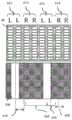
图41A是根据本发明的示意图,其以正视图示出了用于当前时间和空间多路复用实施例的时间多路复用空间光调制器中的像素列的寻址;41A is a schematic diagram showing, in front view, addressing of pixel columns in a temporally multiplexed spatial light modulator for the current temporally and spatially multiplexed embodiment in accordance with the present invention;
图41B是根据本发明的示意图,其以正视图示出了用于当前时间和空间多路复用实施例的时间多路复用空间光调制器中的视差元件的寻址;41B is a schematic diagram showing, in front view, addressing of parallax elements in a time-multiplexed spatial light modulator for the current time- and spatial-multiplexing embodiment, in accordance with the present invention;
图42A是根据本发明的示意图,其以正视图示出了用于当前空间多路复用实施例的时间多路复用空间光调制器中的视差屏障时隙的寻址;42A is a schematic diagram showing, in front view, addressing of parallax barrier slots in a time-multiplexed spatial light modulator for a current spatially-multiplexed embodiment, in accordance with the present invention;
图42B是根据本发明的示意图,其以正视图示出了用于当前空间多路复用实施例的视差屏障的寻址;42B is a schematic diagram showing, in front view, addressing of a parallax barrier for the current spatial multiplexing embodiment, in accordance with the present invention;
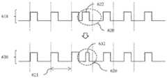
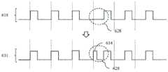
图43A-43C是根据本发明的用于切换定向背光源中的光发射元件的照明脉冲的示意时序图;43A-43C are schematic timing diagrams of illumination pulses for switching light emitting elements in a directional backlight according to the present invention;
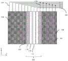
图44是根据本发明的示意图,其以正视图示出了在多视图空间多路复用实施例中与空间光调制器对齐的倾斜视差元件的布置方式;44 is a schematic diagram showing, in front view, the arrangement of oblique parallax elements aligned with a spatial light modulator in a multi-view spatial multiplexing embodiment;
图45是根据本发明的示意图,其以正视图示出了图44的布置方式的图像外观;Figure 45 is a schematic diagram showing, in front view, the appearance of an image of the arrangement of Figure 44 in accordance with the present invention;
图46A-46B是根据本发明的示意图,其以正视图示出了来自图44的布置方式的光学窗与来自定向背光源的光学窗的对齐方式;46A-46B are schematic diagrams showing, in front view, the alignment of optical windows from the arrangement of FIG. 44 with optical windows from a directional backlight, in accordance with the present invention;
图47是根据本发明的示意图,其以正视图示出了来自图44的布置方式的光学窗与来自还包括时间多路复用观察窗的定向背光源的光学窗的对齐;47 is a schematic diagram showing, in front view, alignment of an optical window from the arrangement of FIG. 44 with an optical window from a directional backlight that also includes a time-multiplexed viewing window;
图48是根据本发明的示意图,其以透视图示出了包括布置有空间光调制器和对齐的前透镜状阵列的成像波导的定向显示装置的结构;48 is a schematic diagram showing, in perspective, the structure of a directional display device including an imaging waveguide arranged with a spatial light modulator and an aligned front lenticular array;
图49是根据本发明的示意图,其以透视正视图示出了可切换透镜状阵列的操作;Figure 49 is a schematic diagram showing, in a perspective front view, operation of a switchable lenticular array in accordance with the present invention;
图50-53是根据本发明的示意图,其以侧视图示出了可切换渐变折射率透镜状阵列的布置方式;50-53 are schematic diagrams showing, in side view, arrangements of switchable graded index lenticular arrays in accordance with the present invention;
图54-55是根据本发明的示意图,其以透视正视图示出了布置用于实现自动立体操作的横向模式和纵向模式的可切换自动立体显示器的操作;Figures 54-55 are schematic diagrams showing, in perspective front view, operation of a switchable autostereoscopic display arranged for landscape and portrait modes of autostereoscopic operation, in accordance with the present invention;
图56是根据本发明的示意图,其以透视图示出了包括布置有空间光调制器和两个可切换视差屏障阵列的成像波导的定向显示装置的结构;56 is a schematic diagram showing, in perspective, the structure of a directional display device including an imaging waveguide arranged with a spatial light modulator and two switchable parallax barrier arrays;
图57是根据本发明的示意图,其以俯视图示出了包括空间光调制器和两个对齐的可切换视差屏障阵列的结构;57 is a schematic diagram showing, in a top view, a structure including a spatial light modulator and two aligned switchable parallax barrier arrays in accordance with the present invention;
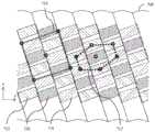
图58A-58B是根据本发明的示意图,其以正视图示出了来自视差元件和对齐的空间光调制器的在横向取向上具有45度窗取向的光学窗阵列,以及来自定向背光源的对齐的光学窗;58A-58B are schematic diagrams showing, in front view, an optical window array with a 45 degree window orientation in a lateral orientation from a parallax element and aligned spatial light modulator, and alignment from a directional backlight the optical window;
图59A是根据本发明的示意图,其以正视图示出了纵向取向图像;Figure 59A is a schematic diagram showing a portrait orientation image in front view in accordance with the present invention;
图59B是根据本发明的示意图,其以正视图示出了来自视差元件和对齐的空间光调制器的在纵向取向上具有45度窗取向的光学窗阵列,以及来自定向背光源的对齐的光学窗;59B is a schematic diagram showing, in front view, an optical window array with a 45 degree window orientation in a longitudinal orientation from a parallax element and aligned spatial light modulators, and aligned optics from a directional backlight window;
图60是根据本发明的示意图,其以正视图示出了视差元件与方形网格上的色彩子像素阵列对齐以实现以45度对齐的光学窗;60 is a schematic diagram showing, in front view, parallax elements aligned with arrays of color subpixels on a square grid to achieve optical windows aligned at 45 degrees, in accordance with the present invention;
图61是根据本发明的示意图,其以正视图示出了视差元件与矩形网格上的色彩子像素阵列对齐以实现以45度对齐的光学窗;61 is a schematic diagram showing, in front view, parallax elements aligned with an array of color subpixels on a rectangular grid to achieve an optical window aligned at 45 degrees, in accordance with the present invention;
图62是根据本发明的示意图,其以侧视图示出了被布置用于实现以45度布置并与来自与相应视差元件对齐的空间光调制器的光学窗对齐的设备;Figure 62 is a schematic diagram showing, in side view, a device arranged to achieve alignment with optical windows from spatial light modulators aligned with corresponding parallax elements in a 45 degree arrangement;
图63是根据本发明的示意图,其以透视正视图示出了被布置用于实现以45度布置并与来自与相应视差元件对齐的空间光调制器的光学窗对齐的设备;Figure 63 is a schematic diagram showing, in a perspective front view, a device arranged to achieve alignment with optical windows from spatial light modulators aligned with corresponding parallax elements in a 45 degree arrangement;
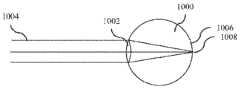
图64A至图64D是根据本发明的示意图,其以平面图示出了针对人眼的各种适应条件;64A to 64D are schematic diagrams showing various adaptation conditions for the human eye in plan view according to the present invention;
图65是根据本发明的示意图,其以平面图示出了被布置用于校正适应条件的显示设备;Figure 65 is a schematic diagram showing, in plan view, a display device arranged to correct for adaptation conditions, in accordance with the present invention;
图66是根据本发明的示意图,其以平面图示出了定向显示设备中的近视校正;FIG. 66 is a schematic diagram illustrating, in plan view, myopia correction in a directional display device in accordance with the present invention;
图67是根据本发明的示意图,其以平面图示出了定向显示设备中的远视或老花眼校正;Figure 67 is a schematic diagram illustrating hyperopia or presbyopia correction in a directional display device in plan view in accordance with the present invention;
图68A是根据本发明的示意图,其以透视图示出了被布置成校正左眼和右眼的适应条件的显示设备;68A is a schematic diagram showing, in perspective, a display device arranged to correct for left and right eye accommodation, in accordance with the present invention;
图68B是根据本发明的流程图,其进一步示出了图68A的操作;Fig. 68B is a flow diagram according to the present invention further illustrating the operation of Fig. 68A;
图69是根据本发明的示意图,其以正视图示出了二维观察窗阵列和对齐的眼睛;Figure 69 is a schematic diagram showing a two-dimensional viewing window array and aligned eyes in front view in accordance with the present invention;
图70A是根据本发明的示意图,其以透视图示出了被布置成校正左眼和右眼的适应条件的显示设备;Figure 70A is a schematic diagram showing, in perspective, a display device arranged to correct for left and right eye accommodation, in accordance with the present invention;
图70B是根据本发明的流程图,其进一步示出了图69的操作;Fig. 70B is a flow diagram according to the present invention further illustrating the operation of Fig. 69;
图70C是根据本发明的示意图,其示出了以与图70A的第一相位相同的方式操作的单目照明系统;Figure 70C is a schematic diagram according to the present invention showing a monocular illumination system operating in the same manner as the first phase of Figure 70A;
图70D是根据本发明的流程图,其示出了图70C的操作;Fig. 70D is a flow chart showing the operation of Fig. 70C in accordance with the present invention;
图71A是根据本发明的示意图,其以透视图示出了被布置成校正左眼和右眼的适应条件的显示设备;Figure 71A is a schematic diagram showing, in perspective, a display device arranged to correct for left and right eye accommodation, in accordance with the present invention;
图71B是根据本发明的流程图,其进一步示出了图69的操作。FIG. 71B is a flowchart further illustrating the operation of FIG. 69 in accordance with the present invention.
具体实施方式Detailed ways
时间多路复用自动立体显示器可有利地通过在第一时隙中将来自空间光调制器所有像素的光导向至第一观察窗并在第二时隙中将来自所有像素的光导向至第二观察窗,而改善自动立体显示器的空间分辨率。因此,眼睛被布置成接收第一观察窗和第二观察窗中的光的观察者将通过多个时隙看到遍及整个显示器的全分辨率图像。时间多路复用显示器可有利地通过使用定向光学元件将照明器阵列引导穿过基本上透明的时间多路复用空间光调制器,而实现定向照明,其中定向光学元件在窗平面中基本上形成照明器阵列的图像。A time-multiplexed autostereoscopic display can advantageously be achieved by directing light from all pixels of the spatial light modulator to a first viewing window in a first time slot and directing light from all pixels to a second time slot in a second time slot. Two viewing windows, which improve the spatial resolution of autostereoscopic displays. Thus, an observer whose eyes are arranged to receive light in the first viewing window and the second viewing window will see a full resolution image throughout the entire display over multiple time slots. Time-multiplexed displays can advantageously achieve directional illumination by directing an array of illuminators through a substantially transparent time-multiplexed spatial light modulator using directional optical elements that are substantially in the window plane An image of the illuminator array is formed.
观察窗的均匀度可有利地与空间光调制器中像素的布置方式无关。有利的是,此类显示器可提供具有低闪烁的观察者跟踪显示器,且对于移动观察者的串扰水平较低。The uniformity of the viewing window can advantageously be independent of the arrangement of the pixels in the spatial light modulator. Advantageously, such displays can provide observer tracking displays with low flicker and low levels of crosstalk for moving observers.
为了在窗平面中实现高均匀度,期望提供具有高空间均匀度的照明元件阵列。可例如通过大小为大约100微米的空间光调制器的像素与透镜阵列的组合,提供时序照明系统的照明器元件。然而,此类像素会遭受对于空间多路复用显示器而言的类似的难题。另外,此类装置可具有较低效率和较高成本,从而需要另外的显示组件。In order to achieve high uniformity in the window plane, it is desirable to provide an array of lighting elements with high spatial uniformity. The illuminator elements of the sequential illumination system may be provided, for example, by a combination of pixels of a spatial light modulator with a size of about 100 microns and an array of lenses. However, such pixels suffer from similar difficulties for spatially multiplexed displays. Additionally, such devices may have lower efficiency and higher cost, requiring additional display components.
可便利地用宏观照明器(例如LED阵列)与通常具有1mm或更大大小的均匀化和漫射光学元件的组合,来实现高窗平面均匀度。然而,照明器元件的大小增加意味着定向光学元件的大小成比例地增加。例如,成像到65mm宽观察窗的16mm宽的照明器可需要 200mm的后工作距离。因此,光学元件的厚度增加可妨碍有效应用于例如移动显示器或大面积显示器。High window plane uniformity can be conveniently achieved with a combination of macroscopic illuminators, such as LED arrays, with homogenizing and diffusing optical elements, typically 1 mm or larger in size. However, an increase in the size of the illuminator elements means a proportional increase in the size of the directional optical elements. For example, a 16mm wide illuminator imaging into a 65mm wide viewing window may require a back working distance of 200mm. Thus, the increased thickness of the optical element can prevent effective application in, for example, mobile displays or large area displays.
为解决上述缺点,如共同拥有的美国专利申请No.13/300,293所述的光学阀有利地可与快速切换透射式空间光调制器组合布置,以在薄型封装中实现时间多路复用自动立体照明,同时提供高分辨率图像及无闪烁观察者跟踪和低串扰水平。描述了观察位置或窗的一维阵列,其可在第一(通常水平)方向上显示不同图像,但在第二(通常竖直)方向上移动时包含相同图像。To address the above disadvantages, an optical valve as described in commonly owned US Patent Application No. 13/300,293 can advantageously be arranged in combination with a fast switching transmissive spatial light modulator to achieve time multiplexed autostereoscopic in a low profile package illumination while providing high resolution images with flicker free observer tracking and low crosstalk levels. A one-dimensional array of viewing positions or windows is described that can display different images in a first (usually horizontal) direction, but contain the same image when moved in a second (usually vertical) direction.
常规的非成像显示背光源通常采用光学波导并且具有来自光源(诸如LED)的边缘照明。然而,应当理解,此类常规的非成像显示背光源与本发明中所述的成像定向背光源之间在功能、设计、结构和操作方面存在许多根本差异。Conventional non-imaging display backlights typically employ optical waveguides and have edge illumination from light sources such as LEDs. It should be appreciated, however, that there are many fundamental differences in function, design, structure and operation between such conventional non-imaging display backlights and the imaging directional backlights described in this disclosure.
一般来讲,例如,根据本发明,成像定向背光源被布置成将来自多个光源的照明在至少一条轴中导向穿过显示器面板到达相应的多个观察窗。每个观察窗通过成像定向背光源的成像系统在光源的至少一条轴中基本上形成为图像。成像系统可形成于多个光源与相应的窗图像之间。以此方式,来自多个光源中的每一者的光对于处于相应观察窗之外的观察者眼睛而言基本上不可见。Generally, for example, in accordance with the present invention, imaging directional backlights are arranged to direct illumination from a plurality of light sources in at least one axis through a display panel to a corresponding plurality of viewing windows. Each viewing window is substantially formed as an image in at least one axis of the light source by an imaging system imaging the directional backlight. An imaging system may be formed between multiple light sources and corresponding window images. In this way, light from each of the plurality of light sources is substantially invisible to the eyes of an observer outside the corresponding viewing window.
相比之下,常规的非成像背光源或光引导板(LGP)用于2D显示器的照明。参见例如,

如本文所用,光学阀是这样的光学结构,其可以是称为例如光阀、光学阀定向背光源和阀定向背光源(“v-DBL”)的光引导结构或装置的类型。在本发明中,光学阀不同于空间光调制器(虽然空间光调制器有时在本领域中可一般称为“光阀”)。成像定向背光源的一个例子为可采用折叠式光学系统的光学阀。光可在基本上无损耗的情况下在一个方向上传播穿过光学阀,可入射到成像反射器上,并且可反向传播,使得光可通过反射离开倾斜的光提取特征而被提取,并导向到观察窗,如美国专利申请序列号13/300,293中所述,所述专利申请全文以引用方式并入本文。As used herein, an optical valve is an optical structure that may be of the type known as light directing structures or devices such as light valves, optical valve directional backlights, and valve directional backlights ("v-DBLs"). In the present invention, optical valves are distinct from spatial light modulators (although spatial light modulators may sometimes be generically referred to in the art as "light valves"). An example of an imaging directional backlight is an optical valve that can employ a foldable optical system. Light can propagate through the optical valve in one direction with substantially no loss, can be incident on the imaging reflector, and can propagate in the reverse direction so that the light can be extracted by reflection off the angled light extraction features, and Guided to the viewing window, as described in US Patent Application Serial No. 13/300,293, which is incorporated herein by reference in its entirety.
如本文所用,成像定向背光源的例子包括阶梯式波导成像定向背光源、折叠成像定向背光源、楔型定向背光源或光学阀。As used herein, examples of imaging directional backlights include stepped waveguide imaging directional backlights, folded imaging directional backlights, wedge-shaped directional backlights, or optical valves.
另外,如本文所用,阶梯式波导成像定向背光源可为光学阀。阶梯式波导是用于成像定向背光源的波导,其包括用于引导光的波导,还包括第一光引导表面;和与第一光引导表面相对的第二光引导表面,还包括散布有被布置为阶梯的多个提取特征的多个光引导特征。Additionally, as used herein, the stepped waveguide imaging directional backlight may be an optical valve. The stepped waveguide is a waveguide for imaging a directional backlight, which includes a waveguide for guiding light, and also includes a first light-guiding surface; and a second light-guiding surface opposite the first light-guiding surface, and further includes a A plurality of light directing features arranged as a plurality of extraction features of a staircase.
此外,如所使用,折叠式成像定向背光源可为楔型定向背光源或光学阀中的至少一者。Furthermore, as used, the folded imaging directional backlight may be at least one of a wedge-shaped directional backlight or an optical valve.
在操作中,光可在示例性光学阀内在第一方向上从输入侧面传播到反射侧面并且可在基本上无损耗的情况下透射。光可在反射侧面反射并且在与第一方向基本上相对的第二方向上传播。当光在第二方向上传播时,光可入射到光提取特征上,所述光提取特征可操作以将光重新导向到光学阀之外。换句话说,光学阀一般允许光在第一方向上传播并且可允许光在第二方向上传播时被提取。In operation, light can propagate in an exemplary optical valve in a first direction from an input side to a reflective side and can be transmitted with substantially no loss. Light may be reflected at the reflective side and propagate in a second direction substantially opposite the first direction. When the light propagates in the second direction, the light may be incident on a light extraction feature operable to redirect the light out of the optical valve. In other words, the optical valve generally allows light to propagate in a first direction and may allow light to be extracted while propagating in a second direction.
光学阀可实现大显示面积的时序定向照明。另外,可采用比光学元件后工作距离更薄的光学元件以将来自宏观照明器的光导向到窗平面。此类显示器可使用光提取特征阵列,所述光提取特征阵列被布置成提取在基本上平行的波导中反向传播的光。Optical valves enable sequential directional illumination of large display areas. Additionally, optical elements that are thinner than the optical element's post-working distance can be employed to direct light from the macro-illuminator to the window plane. Such displays may use an array of light extraction features arranged to extract light counter-propagating in substantially parallel waveguides.
用于与LCD一起使用的薄型成像定向背光源实现方式已由如下提出和说明:3M的例如美国专利No.7,528,893;微软公司(Microsoft)的例如美国专利No.7,970,246,其在本文可称为“wedge type directional backlight”(楔型定向背光源);RealD的例如美国专利申请No.13/300,293,其在本文可称为“optical valve”(光学阀)或“optical valvedirectional backlight”(光学阀定向背光源),所有上述专利全文以引用方式并入本文。Implementations of thin imaging directional backlights for use with LCDs have been proposed and described by, eg, US Patent No. 7,528,893 to 3M; eg US Patent No. 7,970,246 to Microsoft Corporation, which may be referred to herein as "" wedge type directional backlight"; eg, US Patent Application No. 13/300,293 to RealD, which may be referred to herein as "optical valve" or "optical valve directional backlight" source), all of which are incorporated herein by reference in their entirety.
本发明提供了阶梯式波导成像定向背光源,其中光可在例如阶梯式波导的内面之间来回反射,所述阶梯式波导可包括第一侧面和第一组特征。在光沿着阶梯式波导的长度行进时,光可基本上不改变相对于第一侧面和第一组表面的入射角,且因此在这些内面处可不达到介质的临界角。光提取可有利地由第二组表面(阶梯“立板”)实现,所述第二组表面斜向于第一组表面(阶梯“踏板”)。应当注意,第二组表面可不为阶梯式波导的光引导操作的部分,但可被布置成由该结构提供光提取。相比之下,楔型成像定向背光源可允许在具有连续内表面的楔形轮廓波导内引导光。因此,光学阀不是楔型成像定向背光源。The present invention provides a stepped waveguide imaging directional backlight in which light can be reflected back and forth between, for example, interior faces of a stepped waveguide that can include a first side surface and a first set of features. As the light travels along the length of the stepped waveguide, the light may not substantially change the angle of incidence relative to the first side and the first set of surfaces, and thus may not reach the critical angle of the medium at these inner surfaces. Light extraction can advantageously be achieved by a second set of surfaces (stepped "rises") that are inclined to the first set of surfaces (stepped "pedals"). It should be noted that the second set of surfaces may not be part of the light guiding operation of the stepped waveguide, but may be arranged to provide light extraction by the structure. In contrast, wedge-shaped imaging directional backlights may allow light to be directed within a wedge-shaped contoured waveguide with a continuous inner surface. Therefore, the optical valve is not a wedge imaging directional backlight.
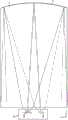
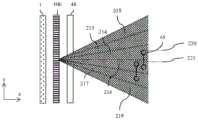
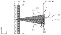
图1A是示出了定向显示装置的一个实施例中的光传播的正视图的示意图,并且图1B 是示出了图1A的定向显示装置中的光传播的侧视图的示意图。1A is a schematic diagram illustrating a front view of light propagation in one embodiment of a directional display device, and FIG. 1B is a schematic diagram illustrating a side view of light propagation in the directional display device of FIG. 1A .
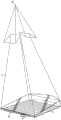
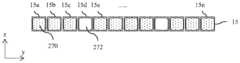
图1A示出了定向显示装置的定向背光源的xy平面中的正视图,并且包括可用于照明阶梯式波导1的照明器阵列15。照明器阵列15包括照明器元件15a至照明器元件15n(其中n是大于1的整数)。在一个例子中,图1A的阶梯式波导1可为阶梯式的、显示器大小的波导1。照明元件15a至照明元件15n是可为发光二极管(LED)的光源。虽然LED在本文作为照明器元件15a–15n来讨论,但可使用其他光源,诸如但不限于二极管源、半导体源、激光源、局域场致发射源、有机发射器阵列等。另外,图1B示出了在xz平面中的侧视图,并且包括如图所示布置的照明器阵列15、SLM(空间光调制器)48、提取特征12、引导特征10和阶梯式波导1。图1B中提供的侧视图为图1A中所示的正视图的替代视图。因此,图1A和图1B的照明器阵列15彼此对应,并且图1A和图1B的阶梯式波导1可彼此对应。FIG. 1A shows a front view in the xy plane of the directional backlight of a directional display device and includes an array of
另外,在图1B中,阶梯式波导1可具有较薄的输入端2和较厚的反射端4。因此,波导1在接收输入光的输入端2与将输入光反射回穿过波导1的反射端4之间延伸。输入端2在跨波导的横向方向上的长度大于输入端2的高度。将照明器元件15a至照明器元件 15n设置在跨输入端2的横向方向上的不同输入位置。Additionally, in FIG. 1B , the stepped
波导1具有相对的第一引导表面和第二引导表面,所述引导表面在输入端2与反射端 4之间延伸,用于通过全内反射沿波导1来回引导光。第一引导表面是平坦的。第二引导表面具有多个光提取特征12,所述光提取特征面向反射端4并且倾斜以在多个方向上反射从反射端穿过波导1引导回的光中的至少一些光,所述多个方向破坏第一引导表面处的全内反射并且允许穿过第一引导表面(例如图1B中朝上)输出,所述输出被供应到SLM 48。The
在此例子中,光提取特征12是反射小平面,但可使用其他反射特征。光提取特征12不引导光穿过波导,而光提取特征12之间的第二引导表面的中间区域在不提取光的情况下引导光。第二引导表面的那些区域是平坦的并且可平行于第一引导表面或以相对较低的倾角延伸。光提取特征12横向于这些区域延伸,使得第二引导表面具有阶梯式形状,所述阶梯式形状包括光提取特征12和中间区域。光提取特征12被取向为在从反射端4反射后使来自光源的光反射穿过第一引导表面。In this example, the light extraction features 12 are reflective facets, but other reflective features may be used. The light extraction features 12 do not guide light through the waveguide, whereas the intermediate regions of the second guiding surface between the light extraction features 12 guide light without extracting light. Those areas of the second guide surface are flat and may extend parallel to the first guide surface or at a relatively low angle of inclination. The light extraction features 12 extend transversely to these regions such that the second guide surface has a stepped shape comprising the light extraction features 12 and the intermediate region. The light extraction features 12 are oriented to reflect light from the light source through the first guide surface after reflection from the
光提取特征12被布置用于将来自在跨输入端的横向方向上的不同输入位置的输入光在相对于第一引导表面的不同方向上导向,所述不同方向取决于输入位置。由于照明元件 15a-15n被布置在不同输入位置处,所以来自相应照明元件15a-15n的光在那些不同方向上反射。这样,照明元件15a-15n中的每个在分布在横向方向中的输出方向上将光导向进入各自的光学窗,所述输出方向取决于输入位置。对于输出光而言,输入位置分布在其中的跨输入端2的横向方向对应于第一引导表面法线的横向方向。如输入端2处限定且对于输出光而言的横向方向在该实施例中保持平行,其中反射端4和第一引导表面处的偏转一般与横向方向正交。在控制系统的控制下,照明器元件15a-15n可选择性地操作以将光导向到可选择的光学窗中。光学窗可单独或成组地用作观察窗。The light extraction features 12 are arranged to direct input light from different input positions in a lateral direction across the input end in different directions relative to the first guide surface, the different directions being dependent on the input position. Since the
反射端4在跨波导的横向方向上可具有正光焦度。在通常反射端4具有正光焦度的实施例中,光轴可参照反射端4的形状限定,例如为穿过反射端4的曲率中心的直线并且与末端4围绕x轴的反射对称的轴线重合。在反射表面4平坦的情况下,光轴可相对于具有光焦度的其他组件(例如光提取特征12,如果它们是弯曲的话)或下文所述的菲涅耳透镜 62类似地限定。光轴238通常与波导1的机械轴重合。The
SLM 48跨波导延伸,是透射的并且调制从其中穿过的光。虽然SLM 48可为液晶显示器(LCD),但这仅仅是举例,并且可使用其他空间光调制器或显示器,包括LCOS、DLP 装置等,因为此照明器可以反射方式工作。在此例子中,SLM 48跨波导的第一引导表面而安置并调制在从光提取特征12反射后穿过第一引导表面的光输出。The
可提供一维观察窗阵列的定向显示装置的操作在图1A中以正视图示出,并且其侧面轮廓在图1B中示出。在操作中,在图1A和图1B中,光可从照明器阵列15(诸如照明器元件15a至15n的阵列)发出,其沿着阶梯式波导1的薄端侧面2的表面x=0位于不同位置y。光可在阶梯式波导1内在第一方向上沿着+x传播,与此同时,光可在xy平面中成扇形射出并且在到达远处弯曲端侧面4后可即刻基本上或完全填充弯曲端侧面4。在传播时,光可在xz平面中展开成一组角度,该组角度高达但不超过引导材料的临界角度。连接阶梯式波导1的底部侧面的引导特征10的提取特征12可具有大于临界角的倾斜角,并且因此在第一方向上沿着+x传播的基本上所有光都可能错过该提取特征12,从而确保了基本上无损耗的前向传播。The operation of a directional display device that can provide a one-dimensional viewing window array is shown in front view in FIG. 1A and its side profile in FIG. 1B . In operation, in FIGS. 1A and 1B , light may be emitted from an illuminator array 15 (such as an array of
继续讨论图1A和1B,可使阶梯式波导1的弯曲端侧面4具反射性,通常通过用反射性材料(诸如银)涂覆而实现,但可采用其他反射技术。光因此可在第二方向上重新导向,顺着引导件在–x方向上返回并且可在xy或显示器平面中基本上准直。角展度可在围绕主要传播方向的xz平面中基本上保持,这可允许光撞击立板边缘并从引导件反射出来。在具有大约45度倾斜的提取特征12的实施例中,可大约垂直于xy显示器平面有效地导向光,其中相对于传播方向基本上保持xz角展度。当光通过折射离开阶梯式波导1时此角展度可增加,但依据提取特征12的反射特性,可略有减小。Continuing the discussion of Figures 1A and 1B, the
在具有未涂覆的提取特征12的一些实施例中,当全内反射(TIR)发生故障时反射可减少,从而挤压xz角轮廓并偏离法线。然而,在涂覆有银或金属化的提取特征的其他实施例中,可保留增大的角展度和中心法线方向。继续描述具有涂覆有银的提取特征的实施例,在xz平面中,光可大约准直地离开阶梯式波导1,并且可与照明器阵列15中的相应照明器元件15a–15n离输入边缘中心的y位置成比例地导向偏离法线。沿着输入边缘2具有独立照明器元件15a–15n于是使光能够从整个第一光导向侧面6离开并以不同外角传播,如图1A中所示。In some embodiments with uncoated extraction features 12, reflection may be reduced when total internal reflection (TIR) fails, squeezing the xz angular profile and away from normal. However, in other embodiments of silver coated or metallized extraction features, the increased angular spread and center normal direction may be preserved. Continuing to describe embodiments with silver-coated extraction features, in the xz plane, light may exit the stepped
用此类装置照明空间光调制器(SLM)48(诸如快速液晶显示器(LCD)面板)可实现自动立体3D,如图2A中的俯视图或从照明器阵列15末端观察的yz平面、图2B中的正视图以及图2C中的侧视图所示。图2A是以顶视图示出光在定向显示装置中的传播的示意图,图2B是以正视图示出光在定向显示装置中的传播的示意图,并且图2C是以侧视图示出光在定向显示装置中的传播的示意图。如图2A、图2B和图2C所示,阶梯式波导1 可位于显示顺序右眼图像和左眼图像的快速(例如,大于100Hz)LCD面板SLM 48的后方。在同步中,可选择性打开和关闭照明器阵列15的具体照明器元件15a至15n(其中n 是大于一的整数),从而借助系统的方向性提供基本上独立地进入右眼和左眼的照明光。在最简单的情况下,一起打开照明器阵列15的多组照明器元件,从而提供在水平方向上具有有限宽度但在竖直方向上延伸的一维观察窗26或光瞳,其中水平间隔的两只眼均可观察到左眼图像;并提供另一个观察窗44,其中两只眼均可主要观察到右眼图像;并提供中心位置,其中两只眼均可观察到不同图像。以此方式,当观察者的头部大约居中对准时可观看到3D。远离中心位置朝侧面移动可导致场景塌缩在2D图像上。Illuminating a spatial light modulator (SLM) 48 (such as a fast liquid crystal display (LCD) panel) with such a device enables autostereoscopic 3D, as in the top view in FIG. 2A or in the yz plane viewed from the end of the
反射端4在跨波导的横向方向上可具有正光焦度。在通常反射端4具有正光焦度的实施例中,光轴可参照反射端4的形状限定,例如为穿过反射端4的曲率中心的直线并且与末端4围绕x轴的反射对称的轴线重合。在反射表面4平坦的情况下,光轴可相对于具有光焦度的其他组件(例如光提取特征12,如果它们是弯曲的话)或下文所述的菲涅耳透镜 62类似地限定。光轴238通常与波导1的机械轴重合。末端4处的圆柱形反射表面可通常为球形轮廓以优化轴上和离轴观察位置的性能。可使用其他轮廓。The
图3是以侧视图示出定向显示装置的示意图。此外,图3示出了可为透明材料的阶梯式波导1的操作的侧视图的另外细节。阶梯式波导1可包括照明器输入侧面2、反射侧面4、可基本上平坦的第一光导向侧面6、以及包括引导特征10和光提取特征12的第二光导向侧面8。在操作中,来自可例如为可寻址LED阵列的照明器阵列15(图3中未示出) 的照明器元件15c的光线16可通过第一光导向侧面6的全内反射和引导特征10的全内反射在阶梯式波导1中被引导至可为镜面的反射侧面4。虽然反射侧面4可为镜面且可反射光,但在一些实施例中光也可能穿过反射侧面4。FIG. 3 is a schematic diagram showing a directional display device in a side view. Furthermore, Figure 3 shows further details of a side view of the operation of the stepped
继续讨论图3,由反射侧面4反射的光线18可进一步通过反射侧面4处的全内反射在阶梯式波导1中引导,并且可被提取特征12反射。入射在提取特征12上的光线18可基本上远离阶梯式波导1的引导模式偏转并且可如光线20所示导向穿过侧面6到达可形成自动立体显示器的观察窗26的光瞳。观察窗26的宽度可至少由照明器的大小、侧面4和提取特征12中的输出设计距离和屈光力确定。观察窗的高度可主要由提取特征12的反射锥角和输入侧面2处输入的照明锥角确定。因此,每个观察窗26代表相对于与标称观察距离处的平面相交的空间光调制器48的表面法线方向而言的一系列单独的输出方向。Continuing the discussion of FIG. 3 , light rays 18 reflected by the
图4A是以正视图示出定向显示装置的示意图,该定向显示装置可由第一照明器元件照明并且包括弯曲的光提取特征。此外,图4A以正视图示出了来自照明器阵列15的照明器元件15c的光线在具有光轴28的阶梯式波导1中的进一步引导。在图4A中,定向背光源可包括阶梯式波导1和光源照明器阵列15。每条输出光线从输入侧面2朝相同观察窗 26导向离开各自照明器15c。图4A的光线可离开阶梯式波导1的反射侧面4。如图4A所示,光线16可从照明器元件15c朝反射侧面4导向。光线18然后可从光提取特征12反射并朝观察窗26离开反射侧面4。因此,光线30可与光线20相交于观察窗26中,或在观察窗中可具有不同高度,如光线32所示。另外,在各种实施例中,波导1的侧面22和侧面24可为透明表面、镜面或涂黑表面。继续讨论图4A,光提取特征12可为细长的,并且光提取特征12在光导向侧面8(光导向侧面8在图3中示出,但在图4A未中示出) 的第一区域34中的取向可不同于光提取特征12在光导向侧面8的第二区域36中的取向。与本文所讨论的其他实施例类似,例如如图3中所示,图4A的光提取特征可与引导特征 10交替。如图4A所示,阶梯式波导1可包括反射侧面4上的反射表面。在一个实施例中,阶梯式波导1的反射端在跨阶梯式波导1的横向方向上可具有正光焦度。Figure 4A is a schematic diagram showing a directional display device in front view which can be illuminated by a first illuminator element and which includes curved light extraction features. Furthermore, FIG. 4A shows in a front view the further guidance of light rays from the
在另一个实施例中,每个定向背光源的光提取特征12在跨波导的横向方向上可具有正光焦度。In another embodiment, the light extraction features 12 of each directional backlight may have a positive optical power in the lateral direction across the waveguide.
在另一个实施例中,每个定向背光源可包括光提取特征12,所述光提取特征可为第二引导表面的小平面。第二引导表面可具有与小平面交替的区域,所述区域可被布置用于将光导向穿过波导而基本上不提取光。In another embodiment, each directional backlight may include light extraction features 12, which may be facets of the second guide surface. The second guide surface may have areas alternating with facets that may be arranged to guide light through the waveguide without substantially extracting light.
图4B是以正视图示出定向显示装置的示意图,该定向显示装置可由第二照明器元件照明。此外,图4B示出了来自照明器阵列15的第二照明器元件15h的光线40和42。侧面4和光提取特征12上的反射表面的曲率可与来自照明器元件15h的光线配合形成与观察窗26横向间隔的第二观察窗44。Figure 4B is a schematic diagram showing a directional display device in front view which can be illuminated by a second illuminator element. Furthermore, FIG. 4B shows light rays 40 and 42 from the
有利的是,图4B中所示的布置可在观察窗26处提供照明器元件15c的实像,其中反射侧面4中的屈光力与可由细长光提取特征12在区域34与36之间的不同取向所引起的屈光力的协作形成实像,如图4A中所示。图4B的布置可实现照明器元件15c至观察窗 26中横向位置的成像的改善的像差。改善的像差可实现自动立体显示器的扩展的观看自由度,同时实现低串扰水平。Advantageously, the arrangement shown in FIG. 4B can provide a real image of
图5是以正视图示出定向显示装置的实施例的示意图,所述定向显示装置具有基本上线性的光提取特征。另外,图5示出了与图1类似的组件布置(其中对应的元件是类似的),其中一个差异是光提取特征12为基本上线性的且彼此平行。有利的是,此类布置可跨显示表面提供基本上均匀的照明,并且与图4A和图4B的弯曲提取特征相比制造起来可更方便。定向波导1的光轴321可为侧面4处的表面的光轴方向。侧面4的光焦度被布置成跨光轴方向,从而入射到侧面4上的光线将具有根据入射光线与光轴321的横向偏移319 而变化的角偏转。5 is a schematic diagram illustrating an embodiment of a directional display device having substantially linear light extraction characteristics in front view. Additionally, Figure 5 shows a similar assembly arrangement to Figure 1 (wherein corresponding elements are similar), with one difference being that the light extraction features 12 are substantially linear and parallel to each other. Advantageously, such an arrangement can provide substantially uniform illumination across the display surface and can be more convenient to manufacture than the curved extraction features of Figures 4A and 4B. The optical axis 321 of the
图6A是示意图,其示出了在第一时隙中时间多路复用成像定向显示装置中的第一观察窗的生成的一个实施例,图6B是示意图,其示出了在第二时隙中时间多路复用成像定向背光源设备中的第二观察窗的生成的另一个实施例,并且图6C是示意图,其示出了时间多路复用成像定向显示装置中的第一观察窗和第二观察窗的生成的另一个实施例。此外,图6A示意性地示出了由阶梯式波导1生成观察窗26。照明器阵列15中的照明器元件群组31可提供朝向观察窗26的光锥17。图6B示意性地示出了观察窗44的生成。照明器阵列15中的照明器元件群组33可提供朝向观察窗44的光锥19。在与时间多路复用显示器的协作中,窗26和44可按顺序提供,如图6C中所示。如果与光方向输出对应地调整空间光调制器48(图6A、图6B、图6C中未示出)上的图像,则对于处于适当位置的观察者而言可实现自动立体图像。用本文所述的所有成像定向背光源可实现类似的操作。应当注意,照明器元件群组31和33各自包括来自照明元件15a至15n的一个或多个照明元件,其中n为大于一的整数。6A is a schematic diagram illustrating one embodiment of the generation of a first viewing window in a time-multiplexed imaging directional display device in a first time slot, and FIG. 6B is a schematic diagram illustrating a second time slot Another embodiment of the generation of a second viewing window in an in-slot time-multiplexed imaging directional backlight device, and FIG. 6C is a schematic diagram illustrating a first observation in a time-multiplexed imaging directional display device Another embodiment of the generation of the window and the second viewing window. Furthermore, FIG. 6A schematically shows the generation of the
图7是示意图,其示出了包括时间多路复用定向显示装置的观察者跟踪自动立体显示设备的一个实施例。如图7所示,沿着轴29选择性地打开和关闭照明器元件15a至15n提供了观察窗的定向控制。可利用相机、运动传感器、运动检测器或任何其他适当的光学、机械或电气装置来监控头部45位置,并且可打开和关闭照明器阵列15的适当照明器元件以向每只眼睛提供基本上独立的图像而不考虑头部45位置。头部跟踪系统(或第二头部跟踪系统)可提供对不止一个头部45、47(头部47在图7中未示出)的监控,并且可向每个观察者的左眼和右眼提供相同的左眼图像和右眼图像,从而向所有观察者提供3D。同样地,用本文所述的所有成像定向背光源可实现类似的操作。FIG. 7 is a schematic diagram illustrating one embodiment of an observer tracking autostereoscopic display device including a time-multiplexed directional display device. As shown in Figure 7, selectively opening and closing the
图8是示意图,其示出了多观察者定向显示装置(作为例子,包括成像定向背光源)的一个实施例。如图8中所示,至少两幅2D图像可朝一对观察者45、47导向,使得每个观察者可观看空间光调制器48上的不同图像。图8的这两幅2D图像可以与相对于图7 所述类似的方式生成,因为这两幅图像将按顺序且与光源同步显示,所述光源的光朝这两个观察者导向。一幅图像在第一阶段中呈现于空间光调制器48上,并且第二图像在不同于第一阶段的第二阶段中呈现于空间光调制器48上。与第一和第二阶段对应,调整输出照明以分别提供第一观察窗26和第二观察窗44。两只眼处于观察窗26中的观察者将感知到第一图像,而两只眼处于观察窗44中的观察者将感知到第二图像。8 is a schematic diagram illustrating one embodiment of a multi-viewer directional display device (including, by way of example, an imaging directional backlight). As shown in FIG. 8 , at least two 2D images can be directed towards a pair of
图9是示意图,其示出了包括成像定向背光源的防窥定向显示装置。2D显示系统也可出于安全和效率目的而利用定向背光源,其中光可主要导向于第一观察者45的眼睛,如图9中所示。另外,如图9中所示,虽然第一观察者45可以能够观察到装置50上的图像,但光不朝第二观察者47导向。因此,防止了第二观察者47观察到装置50上的图像。本发明的实施例中的每一者可有利地提供自动立体、双重图像或防窥显示功能。9 is a schematic diagram illustrating a privacy-resistant directional display device including an imaging directional backlight. 2D display systems may also utilize directional backlights for safety and efficiency purposes, where the light may be directed primarily towards the eyes of the
图10是示意图,其以侧视图示出了时间多路复用定向显示装置(作为例子,包括成像定向背光源)的结构。另外,图10以侧视图示出了自动立体定向显示装置,其可包括阶梯式波导1和菲涅耳透镜62,其被布置用于为跨阶梯式波导1输出表面的基本上准直的输出提供观察窗26。竖直漫射体68可被布置用于进一步扩展观察窗26的高度。然后可通过空间光调制器48对光成像。照明器阵列15可包括发光二极管(LED),其可例如为磷光体转换的蓝色LED,或可为单独的RGB LED。或者,照明器阵列15中的照明器元件可包括被布置成提供单独照明区域的均匀光源和空间光调制器。或者,照明器元件可包括一个或多个激光源。激光输出可通过扫描,例如使用振镜扫描器或MEMS扫描器,导向到漫射体上。在一个例子中,激光可因此用于提供照明器阵列15中的适当照明器元件以提供具有适当输出角度的基本上均匀的光源,并且进一步提供散斑的减少。或者,照明器阵列 15可为激光发射元件的阵列。另外,在一个例子中,漫射体可为波长转换磷光体,使得照明可在不同于可见输出光的波长处。10 is a schematic diagram showing, in side view, the structure of a time-multiplexed directional display device (including, by way of example, an imaging directional backlight). Additionally, Figure 10 shows in side view an autostereotactic display device which may comprise a stepped
现在将描述基于并且包含图1至图10的结构的一些波导、定向背光源和定向显示装置。除了现在将描述的修改形式和/或另外的特征,上述描述同样适用于以下波导、定向背光源和显示装置,但为了简洁起见将不再重复。下文所述的波导可结合到如上文所述的定向背光源或定向显示装置中。类似地,下文所述的定向背光源可结合到如上文所述的定向显示装置中。Some waveguides, directional backlights, and directional display devices based on and incorporating the structures of FIGS. 1-10 will now be described. Except for the modifications and/or additional features that will now be described, the above description applies equally to the following waveguides, directional backlights and display devices, but will not be repeated for the sake of brevity. The waveguides described below can be incorporated into a directional backlight or directional display device as described above. Similarly, a directional backlight as described below can be incorporated into a directional display device as described above.
本实施例涉及光学窗和观察窗。来自定向背光源的光学窗可由光源阵列15中的一个光源形成。来自视差元件和空间光调制器的光学窗可由第一组像素列形成,每列具有该视差元件的一个相应对齐的缝隙。观察窗可包括多个光学窗。This embodiment relates to optical windows and viewing windows. The optical window from the directional backlight may be formed by one of the light sources in the array of
图11A是示意图,其示出了包括定向显示装置和控制系统的定向显示设备。显示装置可包括定向背光源,该定向背光源包括串联布置的波导1、视差元件100和空间光调制器48。另外,触摸屏102可与空间光调制器48串联布置,其中空间光调制器通常布置在触摸屏102与波导之间。还可使用玻璃或膜将触摸屏功能结合在“单元上”或空间光调制器 48的“单元内”。有利地,产生较薄、较轻的显示器。观察窗26可设置在窗平面106处。另外,可由来自波导1的光在窗平面107处产生观察窗27。观察窗27,26可与彼此基本对齐,并且窗平面106,107可基本共面并重叠。空间光调制器48可与视差元件100配合,以在窗平面109处产生另外的观察窗29。如下文所述,观察窗29,26可对齐,并且可具有公共窗平面106,109位置。FIG. 11A is a schematic diagram showing a directional display apparatus including a directional display device and a control system. The display device may comprise a directional backlight comprising the
控制系统的布置方式和操作现在将被描述并且在必要时加以修改的情况下可适用于本文所公开的显示装置中的每个。The arrangement and operation of the control system will now be described and applicable mutatis mutandis to each of the display devices disclosed herein.
定向显示装置包括定向背光源,所述定向背光源包括按照上文所述那样布置的波导1 和照明器元件阵列15。控制系统被布置成可选择地操作照明元件阵列15中的照明元件15a-15n,以与观察窗26提供的光学窗结合,将光导向到可选择光学窗中。The directional display device comprises a directional backlight comprising a
波导1按照上文所述那样布置。反射端4会聚反射光。菲涅耳透镜62(未示出)可被布置成与反射端4配合以在观察者99所观察的观察平面106处实现观察窗26(未示出)。透射空间光调制器(SLM)48可被布置用于接收来自定向背光源的光。另外,漫射体68可设置在波导1与空间光调制器48之间,以基本除去波导1、后反射器300与SLM 48的像素之间的莫尔条纹振动。The
如图11A所示,定向背光源可包括阶梯式波导1和光源照明器阵列15。如图11A所示,阶梯式波导1包括光导向侧面8、反射侧面4、引导特征10和光提取特征12。As shown in FIG. 11A , the directional backlight may include a stepped
控制系统可包括传感器系统,其被布置为检测观察者99相对于显示装置100的位置。传感器系统包括位置传感器70,诸如具有指向观察窗26的图像捕获锥71的相机,和头部位置测量系统72,所述头部位置测量系统可例如包括计算机视觉图像处理系统。控制系统还可包括照明控制器74和图像控制器76,这两者均提供有由头部位置测量系统72提供的被检测到的观察者的位置。The control system may comprise a sensor system arranged to detect the position of the observer 99 relative to the
照明控制器74选择性地操作照明器元件15a-15n以配合波导1将光导向进入观察窗 26。照明控制器74根据头部位置测量系统72所检测到的观察者的位置,来选择要操作的照明器元件15a-15n,使得光导向进入其中的观察窗26处于对应于观察者99的左眼和右眼的位置。这样,波导1的侧向输出方向性对应于观察者位置。
图像控制器76控制SLM 48以显示图像。图像控制器76可连接至空间光调制器48上的像素驱动元件105,这些像素驱动元件被布置成对空间光调制器的像素寻址,如下文详述。在一种操作模式下,为了提供自动立体显示器,图像控制器76和照明控制器74可按照如下方式操作。图像控制器76控制SLM 48以显示时间上多路复用的左眼图像和右眼图像。照明控制器74操作光源15a-15n以将光导向进入观察窗中对应于观察者左眼和右眼的位置,并同步地显示左眼图像和右眼图像。这样,使用时分多路复用技术实现了自动立体效果。
视差控制器104被布置成将驱动信号提供到视差驱动元件108,该视差驱动元件用于根据控制器72调整视差元件100的布置。视差元件100可直接驱动,可为空间多路复用,可为时间多路复用,或可使用空间多路复用和时间多路复用的组合。另外,视差元件100 可布置成在视差模式与非视差模式之间切换,在非视差模式下,视差元件是基本透明的。
以上描述可适用于单独的下列设备、修改形式和/或另外特征中的每者或全部,或其任何组合,现在将描述它们。The above description may apply to each or all of the following devices, modifications and/or additional features individually, or any combination thereof, which will now be described.
在另一个实施例中,定向显示设备还可包括控制系统,其可被布置用于选择性地操作光源以将光导向进入对应于先前所讨论的输出方向的观察窗中。该实施例也可结合如本文所述的定向背光源、定向显示装置、定向显示设备等中的任一者一起使用。In another embodiment, the directional display device may further comprise a control system which may be arranged to selectively operate the light sources to direct light into viewing windows corresponding to the output directions discussed previously. This embodiment may also be used in conjunction with any of the directional backlights, directional display devices, directional display devices, etc. as described herein.
在另一个实施例中,定向显示设备可为具有控制系统的自动立体显示设备。控制系统还可被布置用于控制定向显示装置以按时间显示多路复用的左图像和右图像,并且基本上同步地将所显示的图像导向进入观察窗中对应于观察者的至少左眼和右眼的位置。控制系统可包括传感器系统,所述传感器系统可被布置用于检测显示装置对面的观察者的位置,并且控制系统也可被布置用于将所显示的图像导向进入观察窗中对应于观察者的至少左眼和右眼的位置。观察窗的位置可主要取决于观察者的检测位置。In another embodiment, the directional display device may be an autostereoscopic display device with a control system. The control system may also be arranged to control the directional display device to display the multiplexed left and right images in time, and to direct the displayed images substantially simultaneously into the viewing window corresponding to at least the left eye of the observer and the position of the right eye. The control system may comprise a sensor system which may be arranged to detect the position of an observer opposite the display device, and the control system may also be arranged to direct the displayed image into the viewing window corresponding to the observer's position. At least the position of the left and right eyes. The position of the viewing window may depend primarily on the detection position of the observer.
因此,定向显示装置可包括第一引导表面6和第二引导表面,该第一引导表面被布置用于通过全内反射来引导光,并且第二引导表面包括多个光提取特征12以及位于光提取特征12之间的中间区域10,光提取特征被取向为在允许作为输出光穿过第一引导表面6 离开的方向上引导被引导穿过波导1的光,中间区域被布置用于在不提取光的情况下将光导向穿过波导1。Thus, the directional display device may comprise a
第二引导表面具有阶梯形状,该阶梯形状包括作为光提取特征的小平面12以及中间区域10。定向背光源还包括后反射器300,该后反射器包括反射小平面的线性阵列310。后反射器300可布置成反射来自照明器元件阵列15的光源15a-15n的光,其中光首先透射穿过波导1的多个小平面12,反射离开后反射器300再反射回穿过波导1,以离开穿过第一引导表面6进入光学窗(其可形成观察窗26)中。光提取特征在横向方向上具有正光焦度,例如,如图4B所示。The second guide surface has a stepped shape that includes
定向显示设备可包括定向显示装置和控制系统,所述控制系统被布置成控制阵列15 中的光源,将光导向到光学窗中,以供观察者观察。另外,定向显示设备可包括定向显示装置,该定向显示装置包括:空间光调制器48和视差元件100,其中视差元件100可控制以选择观察窗26的位置;以及控制系统72,74,76,104,该控制系统被布置成控制照明元件阵列15中的照明元件15a-15n,将光导向到光学窗中,以供观察者观察,并且以配合的方式控制视差元件100,将光导向到观察窗26中,以供同一观察者观察。定向显示设备还可包括被布置成检测观察者头部位置的传感器系统70,控制系统72被布置成根据所检测到的观察者头部位置,借助光源控制器74来控制照明元件阵列15中的照明元件15a-15n,并借助视差元件控制器104和视差驱动元件108来控制视差元件100。控制系统72还可被布置成借助控制器76和像素驱动元件105,例如借助空间光调制器上的左眼图像数据和右眼图像数据的交错像素列来控制空间光调制器48,如下所述。A directional display apparatus may comprise a directional display device and a control system arranged to control the light sources in the
图11B是示意图,其以侧视图示出了包括具有小平面反射镜端1102的楔型波导1104 的定向显示装置的结构。波导1104的第一引导表面1105被布置成通过全内反射来引导光,并且第二引导表面1106是基本上平坦的,并以一定角度倾斜以在打破全内反射的方向上导向光,以用于穿过第一引导表面1105输出光。显示装置还包括偏转元件1108,该偏转元件跨波导1104的第一引导表面1105延伸,以用于将光从光源阵列1101朝第一引导表面1105的法线偏转。另外,波导1104还可包括反射端1102,该反射端用于将输入光反射回穿过波导1104,第二引导表面1106被布置成从反射端1102反射后,将光作为输出光偏转穿过第一引导表面1105。例如,反射端以类似于图5所示反射端的方式在横向方向(y 轴)上具有正光焦度。另外,反射端1102的小平面在波导1104内偏转反射光锥,以实现输出耦合在返回路径上。因此,观察窗以类似于图11A所示观察窗的方式产生。另外,定向显示器可包括空间光调制器1110和与空间光调制器1110对齐的视差元件1100,该视差元件还布置用于提供光学窗。类似于图11A所示的控制系统72可布置成提供对定向照明的控制,从而提供来自视差元件和对齐的空间光调制器的观察窗26和窗109。FIG. 11B is a schematic diagram showing, in side view, the structure of a directional display device including a wedge-shaped
图12A是透视图,其以透视图示出了包括布置有空间光调制器的波导1的定向显示装置的结构。反射端4可由菲涅耳镜提供。另外,锥形区域500可布置在波导1的输入处,以增加来自照明器元件阵列15中光源15a-15n的输入耦合效率并增加照明均匀度。具有孔503的屏蔽层502可布置成用于隐藏在波导1边缘处的光散射区域。后反射器300可包括小平面310,这些小平面可弯曲并布置成用于从阵列15的成像光源提供的光学窗组向窗平面27提供观察窗27。光学堆叠504可包括反射偏振器、延迟片层和漫射体。后反射器 300和光学堆叠504还进一步描述于2014年2月21日提交的名称为“Directional backlight” (定向背光源)的美国专利申请No.14/186,862(代理人参考号:95194936.355001),该专利申请全文以引用方式并入本文。FIG. 12A is a perspective view showing, in perspective, the structure of a directional display device including a
空间光调制器48可包括液晶显示器,该液晶显示器可包括输入偏振器406、TFT玻璃基板420、液晶层422、滤色器玻璃基板424和输出偏振器426。可将红色像素516、绿色像素518和蓝色像素520成阵列地布置在液晶层422处。还可在液晶层中布置白色像素、黄色像素、附加的绿色像素或其他颜色像素(未示出),以增加透射效率、色域或感知的图像分辨率。Spatial
在2D操作中,这种显示器可布置成通过将光导向观察者附近的观察窗而不将光浪费在不处于观察者眼睛区域中的方向上,来提供高效率。另外,这种显示器可按需提供高亮度以在具有高环境照明的环境中实现改进的可见度。In 2D operation, such a display can be arranged to provide high efficiency by directing light to a viewing window near the viewer without wasting light in directions that are not in the region of the viewer's eye. Additionally, such displays can provide high brightness on demand for improved visibility in environments with high ambient lighting.
空间光调制器可为例如具有120Hz帧率的时间多路复用空间光调制器,从而实现包括具有60Hz帧率的左图像和右图像的自动立体图像。这种定向显示装置可通过上述时间多路复用来实现自动立体显示。由于背光源的波导组件排布为实现高度的空间和角度均匀性而产生了散射,此类时间多路复用显示器可产生不期望的串扰。另外,需要快速切换空间光调制器,因而增加了成本和复杂度。快速切换空间光调制器中的时间串扰还可降低图像串扰。可通过减少照明时间、不期望地降低显示器亮度和效率来提供串扰控制。The spatial light modulator may be, for example, a time-multiplexed spatial light modulator with a frame rate of 120 Hz, enabling an autostereoscopic image including left and right images with a frame rate of 60 Hz. Such a directional display device can realize autostereoscopic display through the above-mentioned time multiplexing. Such time-multiplexed displays can produce undesirable crosstalk due to the scattering created by the arrangement of the waveguide components of the backlight to achieve a high degree of spatial and angular uniformity. Additionally, fast switching of spatial light modulators is required, thus increasing cost and complexity. Temporal crosstalk in fast switching spatial light modulators can also reduce image crosstalk. Crosstalk control can be provided by reducing illumination time, undesirably reducing display brightness and efficiency.
串扰是由包括左眼图像数据的光泄漏到观察者右眼中(反之亦然)而引起的。串扰可由各种原因引起,这可包括但不限于散射和漫射、宽观察窗重叠、空间光调制器内的电串扰以及不充分的空间光调制器响应时间。高串扰可不期望地使用户感到不舒适、减少工作时间、限制深度呈现并造成其他有害图像伪影。期望的串扰可小于10%、优选地小于5%、更优选地小于2.5%并最优选地小于1%。Crosstalk is caused by leakage of light comprising left eye image data into the observer's right eye (and vice versa). Crosstalk can be caused by a variety of reasons, which can include, but are not limited to, scattering and diffusion, wide viewing window overlap, electrical crosstalk within the spatial light modulator, and insufficient spatial light modulator response time. High crosstalk can undesirably make users uncomfortable, reduce work time, limit depth rendering, and cause other unwanted image artifacts. The desired crosstalk may be less than 10%, preferably less than 5%, more preferably less than 2.5% and most preferably less than 1%.
可能可取的是使用定向背光源减少时间多路复用自动立体显示器的串扰。另外,可能可取的是针对户外使用定向背光源显示器提供高效率和高亮度的优点,尤其是2D应用。It may be desirable to use a directional backlight to reduce crosstalk in time-multiplexed autostereoscopic displays. In addition, it may be desirable to provide the advantages of high efficiency and high brightness for outdoor use directional backlight displays, especially 2D applications.
图12B是示意图,其以透视图示出了包括布置有空间光调制器48和对齐的后视差元件100的定向背光源的图11A的定向显示装置的结构。具体地讲,定向显示装置包括定向背光源,该定向背光源包括波导1,该波导包括用于沿波导1引导光的相对的第一引导表面和第二引导表面,以及照明器元件阵列15的光源15a-15n的阵列15,该光源阵列被布置成在跨波导1的横向方向(y轴)上的不同输入位置处生成输入光,其中第二引导表面被布置成通过第一引导表面6将被引导穿过波导1的光偏转到波导1外,以作为输出光,并且其中该波导被布置成在输出方向上将输出光导向到光学窗中,该输出方向分布在横向方向(y轴)上,其取决于输入光的输入位置;透射空间光调制器48,该透射空间光调制器包括像素516,518,520阵列,该像素阵列被布置成接收来自波导1的输出光并对其进行调制,以显示图像;以及与空间光调制器48串联的视差元件100,该视差元件被布置成将来自空间光调制器的像素的光导向到观察窗中。12B is a schematic diagram showing, in perspective view, the structure of the directional display device of FIG. 11A including a directional backlight disposed with spatial
视差元件100可为视差屏障。该视差元件可包括液晶屏障元件阵列、输入偏振器428、可为电极基板的基板430、液晶层432和可为电极基板的基板434。基板430,434中的至少一者可具有包括屏障元件150的图案化电极阵列,如下文所述。
这种显示装置可通过时间多路复用、空间多路复用、以及时间多路复用和空间多路复用的组合来实现自动立体显示,如下文所述。Such a display device can achieve autostereoscopic display through temporal multiplexing, spatial multiplexing, and a combination of temporal multiplexing and spatial multiplexing, as described below.
图13A是示意图,其以俯视图示出了定向显示装置的包括空间光调制器48和对齐的后视差元件100的部分的结构。视差屏障可包括具有固定层的屏障元件,该固定层包括光吸收区域和光透射区域。可能可取的是屏障可在二维模式之间切换,其中光吸收区域被布置成用于切换到透射状态,以使得不形成视差效应。这种切换屏障可通过图12B和图13A 的布置提供。偏振器428,406和包括图案化电极层的液晶层432被布置成使来自偏振器428 的入射偏振在偏振器406处在吸收和透射之间切换,与图案化电极层的控制有关。因此,偏振器406有利地提供屏障元件100和空间光调制器48的功能。13A is a schematic diagram showing the structure of a portion of a directional display device including the spatial
视差元件100可包括具有透射缝隙444的光吸收区域446。如下文所示,屏障可在以下模式之间切换:(i)每个像素一个缝隙,(ii)每组像素一个缝隙,例如,一组可包括两列像素,(iii)2D操作的完全透射模式。窗形态的几何形状由像素平面与包括层422,432的屏障元件之间的间隔435以及在横向(y轴)方向上空间光调制器上的像素尺寸和期望窗尺寸与观察距离确定。
另外,包括反射偏振器417和延迟器405的层可布置成提供视角的偏振再循环和优化,如图13B所述。Additionally, layers including
使用此类像素分辨率的双视图视差屏障显示器需要使视差屏障100与像素平面422之间存在较小间隔;此类间隔可小于针对基板420,434的期望厚度可实现的间隔。例如,500ppi空间光调制器48可需要350微米的像素422与屏障元件150之间的间隔435。如果提供100微米偏振器406,那么基板420,434将各自具有125微米的厚度,这可降低产量并增加成本。可能可取的是使用高分辨率空间光调制器降低视差屏障显示器的成本。Dual view parallax barrier displays using such pixel resolutions require a small separation between the
在操作中,来自缝隙区域444的光沿光线442被导向到观察窗29。屏障可由多个屏障元件150组成,这些屏障元件可由视差屏障元件100层432的电极提供。因此,缝隙区域444包括多个屏障元件150,如下文针对观察者跟踪的方面所述。In operation, light from
图13B是示意图,其以正视图示出了当与波导1和后反射器300组合时,图13A的光学堆叠中的偏振方向的对齐。后反射器300可包括棱镜结构,该棱镜结构被布置成用于实现入射偏振旋转,如2013年12月20日提交的名称为“Superlens component for directionaldisplay”(用于定向显示器的超透镜组件)的美国专利申请No.14/137,569(代理人参考号95194936.351001),该专利申请全文以引用方式并入本文。FIG. 13B is a schematic diagram showing, in front view, the alignment of polarization directions in the optical stack of FIG. 13A when combined with
在操作中,具有非偏振状态480的光从波导1输出,其中一些直接传播到与偏振器428 对齐的相应偏振器417,这两个偏振器都可具有相对于水平线以45度取向的偏振状态透射方向。一些光被导向到后反射器300,并返回穿过波导1到反射偏振器417。具有偏振状态482的光穿过偏振器417,428,而具有偏振状态486的光通过偏振器417反射穿过波导 1到后反射器300上。反射器300可包括棱镜结构,该棱镜结构旋转偏振状态以使得状态 484被反射并透射穿过波导1和偏振器417,428。穿过延迟器405后,层432中的液晶材料439被切换以在偏振器492处提供光的透射或吸收。延迟器405被布置成旋转来自层432 的偏振光的偏振透射方向,并且可具有例如相对于竖直方向成22.5度的取向。延迟器可为单个延迟器层或可为延迟器堆叠,诸如本领域已知的Pancharatnum堆叠。来自层432的光的45度输出角可旋转45度,以提供入射到可布置成透射偏振状态492的偏振器406和具有偏振透射状态494的输出偏振器426上的水平或竖直偏振状态。因此,空间光调制器48 可包括液晶模式,诸如面内切换、边缘场切换或竖直对齐模式,该模式优选地具有0度的偏振器取向,而视差元件100可包括例如扭转向列模式,该模式优选地具有45度的偏振器取向。In operation, light with
有利地,视差元件100可包括具有用于以高对比度和高孔径比进行基本轴上观察的期望切换性质的低成本液晶模式。空间光调制器48模式可布置成提供广视角、高对比度图像数据。延迟器405可包括一个基板,例如偏振器406的双折射TAC,并且因此具有用于高分辨率LCD的低厚度。Advantageously,
在一些布置中,可能可取的是将间隔435减少至小于可方便地通过减少基板420,434 和偏振器406的厚度来实现的间隔。In some arrangements, it may be desirable to reduce the
图14是示意图,其以俯视图示出了定向显示装置的包括空间光调制器和对齐的后视差元件的部分的结构,该后视差元件还包括单元内偏振器。单元内偏振器407可包括例如线栅偏振器,其上布置有可控制电极。这种单元内偏振器407期望地可从间隔437除去偏振器406和基板434的厚度,并有利地针对极小像素尺寸实现期望的窗尺寸。在空间光调制器48制造期间,线栅偏振器可布置在TFT基板420外侧。14 is a schematic diagram showing, in a top view, the structure of a portion of a directional display device that includes a spatial light modulator and an aligned rear parallax element that also includes an in-cell polarizer. In-
可进一步期望相较于图13A的堆叠厚度而减小总体堆叠厚度,同时维持间隔437。It may further be desirable to reduce the overall stack thickness compared to the stack thickness of FIG. 13A , while maintaining
图15A是示意图,其以俯视图示出了定向显示装置的包括空间光调制器和对齐的后视差元件的部分的结构,该后视差元件还包括两个单元内偏振器。图14的偏振器428和基板430用第二线栅偏振器409和基板430来替代。有利地,相较于图13A的布置而言,总体堆叠厚度可显著减少,同时维持针对自动立体操作期望的窗性质。如下文所述,本实施例的窗成像性质可由视差元件提供,相较于通常可期望地用于现有技术可切换视差屏障显示器的那些,这些视差元件具有更高的串扰水平。因此,线栅偏振器407,409的光学性能可有利地低于已知可切换视差屏障显示器中偏振器428,406的光学性能。15A is a schematic diagram showing, in a top view, the structure of a portion of a directional display device that includes a spatial light modulator and an aligned rear parallax element that also includes two in-cell polarizers. The
在制造期间,SLM 48可在TFT基板420上形成线栅偏振器。随后,视差元件100可在SLM 48的外表面上形成基板430并填充有液晶。接着,可例如借助于化学-机械抛光来使基板430,420,424的夹层结构变薄。有利地,可实现较薄堆叠,在像素层422与屏障层432之间具有期望间隔437。
图15B是示意图,其以俯视图示出了定向显示装置的包括空间光调制器和对齐的后视差元件的部分的结构,该后视差元件包括单元内偏振器。视差元件可有利地由单独结构提供给空间光调制器,从而提高制造产量。相较于图13A的布置,有利地,层422,432之间的间隔437相较于厚度435而减少,因为除去偏振器406的厚度,而用层432内的线栅偏振器替代。另外,相较于图13A,入射在屏障区域上的光线421被反射并可在背光源中循环,而光线423透射并导向到观察窗。因此,系统效率提高。15B is a schematic diagram showing, in a top view, the structure of a portion of a directional display device that includes a spatial light modulator and an aligned rear parallax element that includes an in-cell polarizer. The parallax element can advantageously be provided by a separate structure to the spatial light modulator, thereby increasing the manufacturing yield. Compared to the arrangement of FIG. 13A , the spacing 437 between
图16A至图16B和图17A至图17E是示意图,其以正视图示出了被布置成使视差元件100可控制来选择观察窗29位置的视差元件100的结构。视差元件100可为包括屏障元件阵列150的视差屏障,其可被控制来阻挡或透射光,并且由此选择观察窗的位置。FIGS. 16A-16B and 17A-17E are schematic diagrams showing, in front view, the structure of the
屏障控制器108被布置成借助于电极154来控制屏障元件150,这通常通过将电压施加至屏障元件150区域中的液晶层来实现。因此,当结合光学堆叠的相应偏振器406,428使用时,元件158具有施加以实现显著吸收屏障区域448的电压。元件157具有施加以在缝隙区域444中提供光透射的不同电压(其可为零)。元件157是延迟器元件,其中在 SLM 48的输入处在偏振器406中发生吸收。然而,屏障位置处于延迟器屏障元件150的平面上。为了方便起见,就它们作为视差屏障100的屏障区域的作用而言,此类延迟器区域称为吸收区域。The
第(n+1)电极156可以重复图案连接到第一电极,以有利地减少针对屏障元件150寻址所期望的电极线数目。以此方式,空间光调制器48的每个像素的相应对齐屏障元件以及缝隙可通过相同方式控制。屏障元件间距可布置以提供缝隙区域444,这些缝隙区域具有一定间距,以便在显示器的宽度上实现观察点校正,使得观察窗基本从显示器表面上的所有点导向相同平面,从而为在横向方向上跨整个显示器宽度的移动观察者优化窗切换质量。The (n+1)
在操作中,每个屏障元件150在窗平面109处提供光学窗,并且以组合的方式,光学窗提供观察窗29。图11A所示控制器72可识别移动的观察者,并且可能可取的是调整观察窗29的横向位置。屏障控制器108调节屏障元件150的驱动,以提供新的缝隙区域166,并且由此在横向方向上提供不同的观察窗位置。因此,元件158从吸收操作切换成透射操作,并且元件160从透射操作切换成吸收操作。In operation, each
层432的液晶模式可由例如扭转向列、超级扭转向列、竖直对齐、边缘场切换、平面内切换、Pi-单元或光学补偿弯曲,或其他液晶模式提供。可选择模式以实现至少切换速度、透射率、色度、元件158区域中的黑色电平、元件158之间间隙的区域中的黑色电平、对比度视角和寻址电极孔径比的优化组合。有利地,本实施例可通过液晶模式实现改进性能,这些液晶模式可能不会在具有常规背光源的视差屏障显示器中实现低串扰和其他期望显示特性。The liquid crystal mode of
现将描述屏障元件150之间的间隙区域162的操作。如图17A所示,间隙区域162 可为透射性的,或者如图17B所示,它们可为吸收性的。在已知的显示器中,期望间隙区域是吸收性的,以减少来自吸收区域448中的光透射的串扰。然而,由于缝隙区域444中的吸收,吸收间隙区域还导致显示器亮度损失。有利地,如下所示,本实施例在其中光在屏障区域448中透射的布置中实现降低的串扰,如图17A所示。因此,相较于已知布置,显示器亮度可增加,同时显示器串扰可减小。另外,快速液晶模式诸如Pi-单元模式通常为正常白色操作。The operation of the
图17A至图17B示出了间隙149和162,这两间隙在缝隙区域444和吸收区域448 两者中分别都是透射性的或都是吸收性的。图17C示出了缝隙区域444中的透射间隙149 和吸收区域中的吸收间隙162。有利地,亮度可增加,而串扰可减小。Figures 17A-
在典型可电子切换的视差屏障中,可提供介于2微米和20微米之间的液晶单元间隙。典型单元间隙可介于10微米与15微米之间,例如可为12微米。对于在相邻电极元件150之间的间隙149,这种单元间隙可以实现间隙切换;也就是说,借助于耦合在电极之间的电场,对视差屏障的元件之间区域的液晶材料重新取向。具体地讲,间隙切换可布置成切换屏障区域中的电极间隙,以阻挡光,同时缝隙区域中的电极间隙是透射性的。然而,此类液晶单元间隙可限制屏障100的分辨率。例如,元件之间的间隙149可具有5微米的宽度,并且元件可处于20微米的间距下。如果每个屏障间距需要10个元件150,那么最小屏障间距将为200微米。对于双视图显示器,这种间距可需要100微米间距的LCD;适于 250ppi面板。因此,对于500ppi或更大的空间光调制器,可能可取的是元件150之间的宽度为2.5微米或更小的间隙149。此类间隙可降低视差屏障100的产量,并增加其成本。In a typical electronically switchable parallax barrier, a liquid crystal cell gap of between 2 and 20 microns can be provided. A typical cell gap may be between 10 and 15 microns, for example, may be 12 microns. For
图17D示出了屏障元件布置,相较于图17B的宽度444,其被布置成通过减小缝隙区域168的宽度来实现减小串扰。因此,可向显示器提供可调谐式串扰控制方法,其中缝隙宽度被调节成适合实现观察者跟踪的应用和可靠性。在操作中,较窄缝隙宽度可引起不均匀度增大,这是因为在SLM 48的像素之间的黑色的掩蔽物区域成像到观察窗29中。然而,如果跟踪系统实现可靠质量,那么这些不均匀度对于所跟踪的用户的可见度可减小,并相应调整缝隙宽度,有利地减小图像串扰。Figure 17D shows a barrier element arrangement that is arranged to achieve reduced crosstalk by reducing the width of the
图17E示出了屏障元件150的布置,该布置在用于时间多路复用视差屏障时,可与图 17D的布置反相使用,将参考图37B进行描述。有利地,可切换视差屏障元件以实现低串扰时间多路复用显示器。Figure 17E shows an arrangement of
图18是示意图,其以透视图示出了包括布置有空间光调制器和对齐的前视差元件的成像波导的定向显示装置的结构。相较于图12B,空间光调制器48布置在视差屏障与包括波导1的定向背光源之间。有利地,可增大可实现的观察窗均匀度,因为该装置可以夫琅和衍射方案操作,这与图12B的后部屏障的菲涅耳衍射方案截然不同。18 is a schematic diagram showing, in perspective view, the structure of a directional display device including an imaging waveguide arranged with a spatial light modulator and an aligned front parallax element. Compared to FIG. 12B , the spatial
图19A是示意图,其以正视图示出了包括被灰度寻址的缝隙区域的视差屏障的结构。屏障元件174,176,178可通过借助控制器108和电极154来控制施加到相应屏障元件的电压而具有随在缝隙444上方的位置变化的灰度水平。有利地,从屏障的衍射可因切趾而减小,由此提高窗均匀度。19A is a schematic diagram showing, in front view, the structure of a parallax barrier including a grayscale-addressed slit region.
图19B至图19C是示意图,其以正视图示出了包括缝隙区域的视差屏障的结构,这些缝隙区域被布置成在横向方向上有增加的范围161。元件158的边缘159可在横向(y 轴)方向上布置成具有摆动或其他横向变化,以实现范围161。有利地,可实现在横向方向的切趾,并且可进一步使屏障可见度减小。至少两个元件之间的边缘159可以是相同的,或者可在幅度和相位方面有所变化,诸如图19C所示,以实现减小的莫尔可见度,并使观察窗之间的模糊区域增大,从而提高均匀度。FIGS. 19B to 19C are schematic diagrams showing, in front view, the structure of a parallax barrier including slit regions arranged to have an increased
图20是示意图,其以俯视图示出了包括间隙切换屏障区域的可切换视差屏障的结构。基板430具有均匀电极450以及布置在其表面上的液晶对齐层454。基板434具有图案化电极452,453以及布置在其表面上的液晶对齐层456,其中液晶层432布置在两者之间。将电场施加至相邻电场时,间隙462的区域中的电场方向467扭曲,以在相应电极区域之间提供基本上连续的液晶导向矢取向。FIG. 20 is a schematic diagram showing the structure of a switchable parallax barrier including a gap switching barrier region in a top view. The
图21是示意图,其以俯视图示出了包括边缘场切换屏障元件的可切换视差屏障的结构。基板430可不设有电极,而基板434则具有第一连续电极466、电介质层464、图案化电极462和液晶对齐层456。扭曲的电场线468可在图案化电极562之间的间隙中实现液晶对齐,以在相应电极区域之间提供基本上连续的液晶导向矢取向。21 is a schematic diagram showing the structure of a switchable parallax barrier including fringe field switching barrier elements in a top view. The
如图17B所示,可能可取的是,在电极452,453之间的间隙462中提供光吸收区域。例如,屏障元件150包括输入偏振器428、电极452的区域中的液晶层432,以及偏振器 426。有利地,图20至图21的布置能够在屏障元件150之间的间隙162中实现液晶切换,以减小串扰或增大亮度。As shown in Figure 17B, it may be desirable to provide a light absorbing region in the
可能可取的是,提供可在横向取向与纵向取向之间切换的显示器,例如用于移动显示器。It may be desirable to provide a display that is switchable between a landscape orientation and a portrait orientation, eg for mobile displays.
图22是示意图,其以透视正视图示出了在图12B的可切换自动立体显示器的纵向模式中的光学窗的布置。来自定向背光源的照明器元件阵列15的光源15a-15n的成像的光学窗被布置成提供观察窗26,当显示器200被布置成纵向取向时,该观察窗是水平的。可切换视差屏障100被布置为透射性的,并且该屏障不产生单独的观察窗29。有利地,针对延长的电池寿命,这种显示器可实现高效率操作。另外,可通过打开更多的光学窗并控制相应光学窗的灰度分布来实现广角操作模式。另外,在与广角模式功耗相同的情况下,可实现极高亮度的显示器,例如用于具有高照度水平的户外环境。相较于图12A的布置,可主要通过如图12B所示的偏振器428的平行偏振透射效率来降低这种显示器的效率,例如这种相对效率可为90%。Figure 22 is a schematic diagram showing, in a perspective front view, the arrangement of the optical windows in the portrait mode of the switchable autostereoscopic display of Figure 12B. The imaging optical windows of the
图22的观察窗布置不提供用于自动立体显示操作。The viewing window arrangement of Figure 22 is not provided for autostereoscopic display operation.
图23A至图23C是示意图,其以透视正视图示出了在图12B的可切换自动立体显示器的横向模式中的光学窗的布置。显示器200的来源于定向背光源的观察窗26竖直取向,并且来自视差元件的观察窗29也竖直取向。观察窗26可具有不同于观察窗29的间距204 的间距202。间距202可大于距离204。如图23B所示,间距202可为该间距的半整数倍。如图23C所示,间距202可为间距204的整数倍。期望的是,观察窗26,29可基本对齐以使得窗26,29的左眼观察窗和右眼观察窗对齐。此类布置可有利地减小串扰。23A-23C are schematic diagrams showing, in perspective front view, the arrangement of the optical windows in the landscape mode of the switchable autostereoscopic display of FIG. 12B. The
图24A至图24B是示意图,其以俯视图示出了图12B的可切换显示器的2D观察窗的布置,其中视差元件完全透射。在图24A中,当由阵列15中的少量光源照明时,针对显示器上的一个位置示出了来自波导1的照明锥210。左眼和右眼都在锥210内的观察者 45将看到在照明的显示器上的位置。在窗平面126处的观察者将看到整个照明的显示器。在图24B中,阵列15中具有波导1的更多光源被照明,并实现广角锥212。这种锥提供广泛观察位置,但在给定功耗下具有比图24A的布置更低的效率和亮度。24A-24B are schematic diagrams showing, in top view, the arrangement of the 2D viewing window of the switchable display of FIG. 12B with the parallax element fully transmissive. In Figure 24A,
图24C是示意图,其示出了图24A的布置的观察窗曲线。根据窗平面109中的位置230以亮度曲线233来绘制显示器亮度232。有利地,为了提高效率,可减小观察者45的双眼之间的中间区域235。Figure 24C is a schematic diagram showing the viewing window curve for the arrangement of Figure 24A. Display luminance 232 is plotted with
图25A是示意图,其以正视图示出了用于双视图空间多路复用的空间光调制器和对齐的视差屏障的布置。屏障100具有与空间光调制器48的像素列的横向间距609基本相同的缝隙宽度610;其中SLM 48包括像素列600、602、604和606,各列包括成行红色像素516、绿色像素518和蓝色像素520。左眼数据列(L)600,604可与右眼数据列(R)602,606 交错。有利地,可在窗平面129中产生具有良好均匀度的自动立体窗29。这种布置具有窄观察横向范围的位置,在这些位置处可实现低串扰,如图25D所述。25A is a schematic diagram showing, in front view, an arrangement of spatial light modulators and aligned parallax barriers for dual-view spatial multiplexing.
在本实施例中,像素列组600,604可包括左像素组596,并且像素列组602,606可包括右像素组598。更普遍地,组596,598可以是分别包括左眼图像数据和右眼图像数据的像素组。这些组还可包括不布置成列的像素,例如以倾斜阵列布置,如本文所述。In this embodiment,
可能可取的是,增大实现低串扰的观察自由度范围,同时维持观察窗29的高均匀度。It may be desirable to increase the range of viewing degrees of freedom to achieve low crosstalk, while maintaining a high uniformity of
图25B是示意图,其以正视图示出了用于四视图空间多路复用的空间光调制器和对齐的视差屏障的布置。在该实施例中,屏障的每个缝隙444上覆有四列像素,并且各列被布置成与右眼像素数据组614,618交错的左眼像素数据组612,616。缝隙区域444的宽度610与像素列的间距相同,以实现较高的窗均匀度。有利地,相较于图25A的布置,增加低串扰的观察自由度。25B is a schematic diagram showing, in front view, an arrangement of spatial light modulators and aligned parallax barriers for four-view spatial multiplexing. In this embodiment, each slit 444 of the barrier is overlaid with four columns of pixels, and the columns are arranged as left eye
图25C是示意图,其以俯视图示出了用于双视图空间多路复用的空间光调制器和对齐的视差屏障的角输出。朝观察者45导向左眼观察锥215,216,219和右眼观察锥218,214和217。在第一观察者45位置220处,右眼看到右眼图像,左眼看到左眼图像,并且会看到标准图像;并且在第二位置221处,右眼看到左眼图像,左眼看到右眼图像,并且会看到反视立体图像。25C is a schematic diagram showing the angular output of a spatial light modulator and aligned parallax barrier for dual view spatial multiplexing in a top view. Left
图25D是示意图,其示出了在图25A的布置方式中,窗平面中的光学窗亮度与位置的变化关系。图25C中的位置221的反视立体图像是不期望的,它会导致视觉疲劳和用户困惑。另外,如将示出,反视立体图像在显示屏中形成增加的串扰。考虑到观察者238的左眼,来自图25A的布置的右眼观察窗曲线29将具有基本上三角形的曲线242,该基本上三角形的曲线具有相邻的右眼观察窗曲线240,244。在操作中,光将通过相邻的观察窗之间的漫射体和其他散射机制进一步渗透,如箭头239,241所指示。因此,来自右眼观察窗240,244的光将被导向到观察者238的右眼。Fig. 25D is a schematic diagram showing optical window luminance versus position in the window plane in the arrangement of Fig. 25A. The reverse stereoscopic image of
可能可取的是,减少显示器串扰并减少反视立体区的出现,并且减小图像串扰。It may be desirable to reduce display crosstalk and reduce the occurrence of antistereoscopic regions, and reduce image crosstalk.
图26A是示意图,其以俯视图示出了用于双视图空间多路复用的定向照明与空间光调制器和对齐的视差屏障的组合的角输出。可布置作为自动立体显示设备的定向显示设备,其中:视差元件100被布置成将光从空间光调制器48的第一组空间多路复用像素596和第二组空间多路复用像素598导向到左眼观察窗和右眼观察窗29(通过平面109与锥214,216的相交部分示出)中,以供观察者45的左眼和右眼观察;控制系统72,76被布置成控制空间光调制器48在第一组空间多路复用像素596和第二组空间多路复用像素598上显示左眼图像和右眼图像;并且控制系统72,74被布置成控制照明器元件阵列15中的光源 15a-15n将光导向到光学窗26(通过平面106与锥210的相交部分示出)中,以供观察者 45的左右两眼观察。26A is a schematic diagram showing, in a top view, the angular output of a combination of directional illumination for dual view spatial multiplexing with a spatial light modulator and an aligned parallax barrier. A directional display device may be arranged as an autostereoscopic display device, wherein: the
通过包括波导1的定向背光源提供图24A中由锥210提供的观察窗26,而锥214,216提供的观察窗29被导向到观察者45。在位置220中可看到标准图像,而在位置221中,可用右眼看到单个图像,从而得到2D图像的外观。
图26B是示意图,其示出了在图26A的布置方式中,窗平面中的光学窗亮度与位置的变化关系。因此,消除窗244,并且如箭头239所示从窗240散射的光被导向到观察者 238的左眼。有利地,该系统的串扰基本减小,并且可消除反视立体区。Figure 26B is a schematic diagram showing the optical window brightness versus position in the window plane in the arrangement of Figure 26A. Thus,
图25A的布置例如使横向显示分辨率减小一半。可能可取的是实现显示器的全分辨率,如将参考图27A至图27B所述。The arrangement of FIG. 25A reduces the lateral display resolution by half, for example. It may be desirable to implement the full resolution of the display, as will be described with reference to Figures 27A-27B.
图27A是示意图,其以俯视图示出了用于双视图空间多路复用和时间视图多路复用的定向照明与空间光调制器和对齐的视差屏障的组合的角输出。在这个实例中,由锥210给出的窗26和由锥214,216,215,217给出的窗29不准确地对齐,并且一些小残余相邻反视立体锥也会被导向到观察者45,从而提供小反视立体照明的侧锥215,217。27A is a schematic diagram showing, in top view, the angular output of directional illumination for dual-view spatial multiplexing and temporal view multiplexing in combination with spatial light modulators and aligned parallax barriers. In this example, the
图27B是示意图,其以正视图示出了用于双视图空间多路复用和时间视图多路复用的空间光调制器和对齐的视差屏障的布置。因此,定向显示设备可为自动立体定向显示设备,其中:视差元件100可控制地选择观察窗29的位置;控制系统72,104被布置成以时间多路复用的方式控制视差元件100:(a)将光从第一组空间多路复用像素596和第二组空间多路复用像素598导向到左眼观察窗和右眼观察窗29中,以供观察者45的左眼和右眼观察;并且(b)将光从第一组像素596和第二组像素598导向到反向的左眼观察窗和右眼观察窗29中,以供观察者的左眼和右眼观察,控制系统72,104被布置成以与控制视差元件同步地、以时间多路复用的方式控制空间光调制器48:(a)当来自第一组空间多路复用像素596 和第二组空间多路复用像素598的光导向到左眼观察窗和右眼观察窗中时,分别在第一组空间多路复用像素和第二组空间多路复用像素上显示左眼图像和右眼图像;并且(b)当来自第一组空间多路复用像素596和第二组空间多路复用像素598的光导向到反向的右眼观察窗和左眼观察窗29中时,分别在第一组空间多路复用像素和第二组空间多路复用像素上显示右眼图像和左眼图像;并且控制系统被布置成控制光源15a-n将光导向到光学窗26 中,以供观察者45的双眼观察。27B is a schematic diagram showing, in front view, the arrangement of spatial light modulators and aligned parallax barriers for dual-view spatial multiplexing and temporal view multiplexing. Thus, the directional display device may be an autostereoscopic display device in which: the parallax element 100 controllably selects the position of the viewing window 29; the control systems 72, 104 are arranged to control the parallax element 100 in a time-multiplexed manner: (a) directs light from the first set of spatially multiplexed pixels 596 and the second set of spatially multiplexed pixels 598 into the left and right eye viewing windows 29 for viewing by the left and right eyes of the observer 45 and (b) directing light from the first set of pixels 596 and the second set of pixels 598 into opposing left and right eye viewing windows 29 for viewing by the observer's left and right eyes, controlling the system 72,104 are arranged to control the spatial light modulator 48 in a time-multiplexed manner in synchronization with the control of the parallax elements: (a) when the output from the first set of spatially multiplexed pixels 596 and the second set of spatially multiplexed pixels When the light from pixel 598 is directed into the left eye viewing window and the right eye viewing window, the left eye image and the right eye image are displayed on the first set of spatially multiplexed pixels and the second set of spatially multiplexed pixels, respectively; and (b) when light from the first set of spatially multiplexed pixels 596 and the second set of spatially multiplexed pixels 598 is directed into opposing right-eye and left-eye viewing windows 29, respectively, A right eye image and a left eye image are displayed on one set of spatially multiplexed pixels and a second set of spatially multiplexed pixels; and the control system is arranged to control the light sources 15a-n to direct light into the optical window 26 for Both eyes of observer 45 observe.
SLM 48可为高帧率装置,从而例如相较于仅具有空间多路复用的显示器的60Hz,在 120Hz帧率下提供左图像和右图像。在第一相位(如图27A至图27B的上部部分所示) 中,观察锥214来自源于面板以及对齐的右眼像素列上的第一屏障缝隙区域444的右眼图像。在第二相位(如图27A至图27B的下部部分所示)中,观察锥225来自源于面板以及对齐的右眼像素列上的第二屏障缝隙区域444的右眼图像(R’,其中R’是指第一相位中所用R数据的互补交错右眼数据的数据),面板以及对齐的右眼像素列两者在第一相位与第二相位之间平移。R’数据601,603,605,607可不同于R数据600,602,604,606,以提高显示分辨率,并且类似地,对于L和L’数据也是如此。The
有利地,显示图像分辨率可提高,同时可实现较高的窗均匀度和低串扰。Advantageously, the display image resolution can be increased, while higher window uniformity and low crosstalk can be achieved.
可能可取的是增大图26A和图27A的布置的观察自由度。It may be desirable to increase the viewing freedom of the arrangements of Figures 26A and 27A.
可能可取的是将定向图像诸如自动立体图像提供给多个观察者。It may be desirable to provide directional images, such as autostereoscopic images, to multiple observers.
图27C至图27E是示意图,其以俯视图示出了包括波导1、空间光调制器48和用于多个观察者的对齐的视差屏障100的定向背光源的布置。图27C示出了当通过广角锥212 提供照明时,用于观察者45,47的空间多路复用自动立体显示器的多个瓣。提供多个标准图像以及反视立体图像,这会使观察者45,47分散注意力并感到困惑。图27D示出了来自包括波导1和阵列15的定向背光源的观察窗211,213的布置。在该实施例中,可独立地跟踪锥211,213,使得可有利地跟踪多个观察者。27C-27E are schematic diagrams showing, in top view, an arrangement of a directional backlight including a
图27E示出了图27C至图27D的布置的组合结果。有利地,观察者45,47都可被提供标准自动立体3D图像。Figure 27E shows the combined result of the arrangements of Figures 27C-27D. Advantageously, both
图28是示意图,其以俯视图示出了用于具有观察者跟踪的双视图空间多路复用的定向照明与空间光调制器和对齐的视差屏障的组合的角输出。图29A是示意图,其以正视图示出了用于具有观察者跟踪的双视图空间多路复用的空间光调制器和对齐的视差屏障的布置。28 is a schematic diagram showing, in a top view, the angular output for a combination of dual-view spatially multiplexed directional illumination with observer tracking and a spatial light modulator and aligned parallax barrier. 29A is a schematic diagram showing, in front view, an arrangement of spatial light modulators and aligned parallax barriers for dual-view spatial multiplexing with observer tracking.
视差元件100可控制来选择观察窗29的位置,并且控制系统72,104还可被布置成控制视差元件100将光导向到左观察窗和右观察窗29中。The
针对在显示器上的一个位置由锥210表示的观察窗26和由锥214,216表示的观察窗 29可响应于观察者跟踪系统来导向,使得对于在位置220,221之间移动的观察者45来说,维持具有低串扰、高均匀度的标准图像。因此,可通过类似于图16A至图16B中所示方式并配合对屏障100中屏障元件150的控制,对波导1的阵列15中的光源的选择进行调整。因此,缝隙444中间的位置271可配合LED阵列15寻址的变化移动到位置273。
该空间光调制器的像素阵列可布置为行和列。黑色的掩蔽物区域608可布置在像素列之间。黑色的掩蔽物区域可通过视差元件成像到窗平面109,从而形成不均匀度。视差元件诸如视差屏障缝隙的孔宽610可用于从窗平面中的黑色掩蔽物区域消除不均匀度的可见度。然而,为实现高均匀度而增大的缝隙宽度610增加图像串扰。The pixel array of the spatial light modulator can be arranged in rows and columns.
可能可取的是,维持窗平面中的高亮度均匀度,同时进一步减小在像素列之间具有黑色掩蔽物的空间多路复用显示器中的图像串扰。It may be desirable to maintain high luminance uniformity in the window plane while further reducing image crosstalk in spatially multiplexed displays with black masks between pixel columns.
在图25B的实施例中,可通过针对每个观察窗使用多个像素列来增大基板420,434的厚度,由此,可将由单个像素列提供的光学窗减半,并且可使基板厚度基本增大,从而降低成本。In the embodiment of Figure 25B, the thickness of the
图29B是示意图,其以正视图示出了用于四视图空间多路复用的空间光调制器和对齐的视差屏障的布置。如上所述,由每列像素产生的光学窗可例如为32mm。对于使用100微米厚偏振器406的800ppi LCD来说,300mm视距所需要的屏障与像素的总间隔为约450 微米,并且基板厚度为约175微米。有利地,对于高分辨率空间光调制器,产量提高,并且成本降低。另外,间隙149具有提高的产量和降低的成本的宽度。29B is a schematic diagram showing, in front view, an arrangement of spatial light modulators and aligned parallax barriers for four-view spatial multiplexing. As mentioned above, the optical window created by each column of pixels may be, for example, 32 mm. For an 800 ppi LCD using a 100 micron
在操作中,左像素列可具有稍不同的左像素数据L1,L2和右像素数据R1,R2,以实现比视差屏障孔间距提供的更大的感知图像分辨率。In operation, the left pixel column may have slightly different left pixel data L1 , L2 and right pixel data R1 , R2 to achieve greater perceived image resolution than the parallax barrier aperture spacing provides.
图30是示意图,其示出了在图28的布置方式中,窗平面中的光学窗亮度与位置的变化关系。由于视差屏障100的宽缝隙444,因此得以维持窗平面处的均匀度246。图31 是示意图,其示出了在具有减小的缝隙444宽度610的布置方式中,窗平面中的总观察窗亮度与位置的变化关系。减小缝隙宽度通过修改单个视图数据的窗曲线来改进串扰,从而提供观察窗240,242,244;然而,由于黑色掩蔽物区域608的成像,总亮度曲线246具有增加的不均匀度。不均匀窗曲线是不利的,因为随着观察者或显示器运动,显示器可出现闪烁。另外,对于远离视差元件窗平面109的观察者,显示器可具有不均匀的亮度。FIG. 30 is a schematic diagram showing optical window brightness versus position in the window plane in the arrangement of FIG. 28 . Due to the
图32是示意图,其示出了在用于图29A的布置方式中,窗平面中的总观察窗亮度与位置的变化关系,该布置方式还包括补偿亮度分布。视差元件100和空间光调制器48配合以产生具有不均匀横向窗亮度分布246的观察窗27,并且定向背光源可布置成产生具有不均匀横向窗亮度分布250的光学窗26并对观察窗的横向窗亮度分布246的不均匀度进行补偿。所得亮度232分布252因此是基本均匀的。分布252针对朗伯型显示器示出。在其他实施例中,分布252可具有例如中心最大值,以实现更高增益分布。然而,在无最大值或最小值的情况下,总亮度分布平缓变化,由此实现基本上均匀的显示器外观。Figure 32 is a schematic diagram showing total viewing window brightness versus position in the window plane in the arrangement used in Figure 29A, which also includes compensating the brightness distribution.
定向背光源可包括阵列15、波导1和光学堆叠504,它们被布置成提供观察窗26。定向背光源还可包括后反射器300,该后反射器被布置成提供观察窗27,该观察窗可与观察窗27对齐。A directional backlight may include
有利地,当SLM 48包括黑色掩蔽物列以覆盖寻址电路时,观察者238,240的每只眼睛看到基本上相同的亮度,并且显示器串扰减小。Advantageously, when the
图33A至图33B是示意图,其以侧视图和正视图示出了包括补偿特征的LED阵列,该补偿特征包括透射元件256。图34是示意图,其示出了在图33A至图33B的LED阵列上,补偿特征透射率264与位置262的变化关系。图35是示意图,其示出了在用于图33A 至图33B的布置方式中,窗平面中的亮度与位置230的变化关系。除了透射元件256之外或替代该透射元件,LED阵列可穿过量子点材料来照明,以改进所得显示器的色度。33A-33B are schematic diagrams showing an LED array including a compensation feature including a
定向背光源1,15因此还可包括透射元件256,该透射元件被设置在光源15a-n上方并且具有呈曲线266的在横向方向上变化的透射率264,以便提供定向背光源1,15产生的光学窗26的不均匀横向窗亮度232分布268。术语“定向背光源1,15”在本文中可用于指波导1和光源阵列15。换句话说,背光源1,15可仅出于论述目的而非限制目的包括波导 1和光源阵列15。透射元件258具有分别有第一透射率和第二透射率的区域258,260。透射元件256还可为可切换透射元件,诸如布置在阵列15与波导1的输入侧2之间的液晶元件。这种可控制元件可被布置成响应于跟踪系统中观察者45的位置来平移透射率曲线 266。The
有利地,像素列之间包括黑色掩蔽物区域608的本实施例的均匀度和串扰可改进。Advantageously, the uniformity and crosstalk of this embodiment including
图36是示意图,其以侧视图示出了对LED阵列15的寻址,以便实现观察窗亮度分布补偿特征。阵列15中的LED 15a-n具有输出光通量分布,该输出光通量分布被布置成提供图35所示的窗亮度232分布268。因此,LED 15d具有比LED 15a的光通量270更高的输出光通量272。有利地,在观察者跟踪期间,光通量分布可随着观察窗26平移。FIG. 36 is a schematic diagram showing, in side view, addressing of the
可能可取的是,通过来自定向背光源1,15的观察窗26与来自视差元件100和空间光调制器48的观察窗27之间的配合来进一步降低显示器系统的串扰。It may be desirable to further reduce the crosstalk of the display system by cooperation between the
图37A是示意图,其以俯视图示出了来自定向背光源的定向照明的时间多路复用的角输出。在包括快速响应SLM 48诸如120Hz LCD的实施例中,观察窗26可通过时间多路复用方式产生,从而以第一相位和第二相位分别将输出锥222和224提供到观察者45的右眼和左眼。在该实施例中,可将视差元件布置为基本透射的。37A is a schematic diagram showing, in a top view, the time-multiplexed angular output of directional illumination from a directional backlight. In embodiments that include a
有利地,这种布置可以全分辨率向多个观察者提供自动立体图像,并且因此,用户可通过用软件控制视差元件设置来选择显示器系统的多用户情况的操作。这种定向背光源的最小可实现串扰可受到从反射端4返回到输入侧2并返回到光学系统中的光的限制。可能可取的是进一步减小这种布置的串扰。Advantageously, this arrangement can provide autostereoscopic images to multiple observers at full resolution, and thus, the user can select the operation of the display system for multi-user situations by controlling the parallax element settings in software. The minimum achievable crosstalk of such a directional backlight may be limited by the light returning from the
图37B是示意图,其以俯视图示出了与视差元件100和对齐的空间光调制器48的时间多路复用输出配合的来自定向背光源1,15的定向照明的时间多路复用角输出,该视差元件被布置成提供缝隙区域444和吸收区域448。37B is a schematic diagram showing, in top view, the time-multiplexed angular output of directional illumination from
图37C是示意图,其以正视图示出了用于双视图空间多路复用(包括空白,例如黑色像素列(标记K))和时间多路复用的空间光调制器和对齐的视差屏障的布置方式。37C is a schematic diagram showing, in front view, a spatial light modulator and aligned parallax barrier for dual-view spatial multiplexing (including blank, eg, black pixel columns (labeled K)) and temporal multiplexing arrangement.
定向显示设备可为自动立体显示设备,其中:视差元件100被布置成将光从第一组空间多路复用像素596和第二组空间多路复用像素598导向到左眼观察窗和右眼观察窗29中,以供观察者45的左眼和右眼观察;控制系统72、74被布置成以时间上多路复用的方式控制光源15a-n,将光导向到左眼光学窗628和右眼光学窗626中,以供观察者45的左眼和右眼观察;控制系统72、76被布置成与控制阵列15中的光源15a-n同步地、以时间上多路复用的方式控制空间光调制器48:(a)在光源15a-n将光导向到左眼光学窗628中时,分别在第一组像素596和第二组像素598上显示左眼图像(L)和空白图像(K);并且(b)在光源15a-n将光导向到右眼光学窗626中时,分别在第一组像素596和第二组像素598上显示空白图像(K)和右眼图像(R)。另外,视差元件100可控制来选择观察窗627、629的位置,并且控制系统72、104还可被布置成控制视差元件100将光导向到左观察窗627和右观察窗629中。The directional display device may be an autostereoscopic display device in which the parallax element 100 is arranged to direct light from the first set of spatially multiplexed pixels 596 and the second set of spatially multiplexed pixels 598 to the left eye viewing window and the right in the eye viewing window 29 for viewing by the left and right eyes of the observer 45; the control systems 72, 74 are arranged to control the light sources 15a-n in a time-multiplexed manner, directing the light to the left eye optical window 628 and right eye optical window 626 for viewing by the left and right eyes of the observer 45; the control systems 72, 76 are arranged to be multiplexed in time synchronously with the light sources 15a-n in the control array The spatial light modulator 48 is controlled in such a way that: (a) as the light sources 15a-n direct light into the left eye optical window 628, a left eye image is displayed on the first set of pixels 596 and the second set of pixels 598, respectively (L) and a blank image (K); and (b) display a blank image (K) and a right image on the first set of pixels 596 and the second set of pixels 598, respectively, as the light sources 15a-n direct light into the right eye optical window 626 Eye image (R). Additionally, the
在处于第一相位中的操作中,锥222由定向背光源1、15提供,以得到观察窗26诸如窗627,并且锥214、217、218由视差元件100和空间光调制器48提供,以在窗平面 106、107处得到观察窗27诸如窗626。如图37C所示,第一相位中的空间光调制器48 上示出的数据包括,具有空白(K)数据的奇数列601、605和具有右(R)眼数据的偶数列603、 607,该空白数据通常是黑色数据。In operation in the first phase,
在处于第二相位中的操作中,锥224由定向背光源1、15提供,以得到观察窗27诸如窗629,并且锥214、217、218由视差元件100和空间光调制器48提供,以在窗平面 106、107处得到观察窗27诸如窗628。如图37C所示,第二相位中的空间光调制器48 上示出的数据包括,具有空白(K)数据的偶数列603、607和具有右(R)眼数据的奇数列601、 605,该空白数据通常是黑色数据。In operation in the second phase,
在两个相位中,视差元件100可具有针对给定观察者位置的固定位置,并且可被布置成响应于观察者45的移动,来配合阵列15光源的跟踪而进行跟踪。In both phases,
如下文将描述的那样,相较于图27A-27B的布置方式,图37B-图37D的布置方式可实现串扰减小。As will be described below, the arrangement of FIGS. 37B-37D may achieve a reduction in crosstalk compared to the arrangement of FIGS. 27A-27B.
图37D是示意图,其以正视图示出了用于双视图空间多路复用(包括固定位置黑色像素列)和时间多路复用视差元件的空间光调制器和对齐的视差屏障的布置方式,这些元件进而被布置成提供低串扰的增高的显示分辨率。37D is a schematic diagram showing, in front view, the arrangement of spatial light modulators and aligned parallax barriers for dual-view spatial multiplexing (including fixed-position black pixel columns) and time multiplexing parallax elements , these elements are in turn arranged to provide increased display resolution with low crosstalk.
定向显示设备可为自动立体定向显示设备,其中:视差元件100可控制来选择观察窗 29的位置;控制系统72、76、104被布置成以时间上多路复用的方式控制视差元件100:(i)将光从与第二组像素598在空间上多路复用的第一组像素596导向到左眼观察窗629中,以供观察者45的左眼观察;并且(ii)将光从第一组像素596导向到右眼观察窗627中,以供观察者45的右眼观察。The directional display device may be an autostereoscopic display device, wherein: the
控制系统72、74、104可布置成与控制视差元件100同步地、以时间上多路复用的方式控制光源:(i)在视差元件100将光从第一组像素596导向到左眼观察窗629中时,进入左眼光学窗628中,以供观察者45的左眼观察;并且(ii)在视差元件100将光从第一组像素596导向到右眼观察窗627中时,进入右眼光学窗626中,以供观察者45的右眼观察。控制系统72、74、76、104可被布置成与控制视差元件100同步地、以时间上多路复用的方式控制空间光调制器48:(a)在视差元件100将光从第一组像素596导向到左眼观察窗 629中时,分别在第一组像素596和第二组像素598上显示左眼图像(L)和空白图像(K);并且(b)在视差元件100将光从第一组像素596导向到右眼观察窗627中时,分别在第一组像素596和第二组像素598上显示右眼图像(R)和空白图像(K)。The
换句话说,像素组596保持空白(K),而像素组598被布置有左眼图像(L)或右眼图像 (R),使得图像数据切换在单个组上发生。有利地,因在图37C中的图像数据与空白(K)之间切换像素数据产生的串扰可通过在可能类似的图像数据之间进行切换来减小,其中左眼数据与右眼数据的相关性可能要超过空白与左眼数据或右眼数据的相关性。In other words,
进一步可取的是,增大图37B-图37C的实施例的分辨率。It is further desirable to increase the resolution of the embodiment of Figures 37B-37C.
图37E是示意图,其以正视图示出了用于双视图空间多路复用(包括黑色像素列)和时间多路复用的空间光调制器和对齐的视差屏障的布置方式,这些元件进而被布置成提供低串扰的增高的显示分辨率。37E is a schematic diagram showing, in front view, the arrangement of spatial light modulators and aligned parallax barriers for dual view spatial multiplexing (including black pixel columns) and time multiplexing, these elements in turn Arranged to provide increased display resolution with low crosstalk.
定向显示设备可为自动立体定向显示设备,其中:视差元件100可控制来选择观察窗 29的位置;控制系统72、76、104被布置成以时间上多路复用的方式控制视差元件100:(i)分别将光从第一组空间多路复用像素596和第二组空间多路复用像素598导向到左眼观察窗629和右眼观察窗627中,以供观察者45的左眼和右眼观察;并且(ii)分别将光从第一组空间多路复用像素596和第二组空间多路复用像素598导向到右眼观察窗627和左眼观察窗629中,以供观察者45的右眼和左眼观察。The directional display device may be an autostereoscopic display device, wherein: the
控制系统72、74可被布置成控制光源15a-n:(i)在视差元件100将光从第一组像素596 导向到左眼观察窗629,以及从第二组像素598导向到右眼观察窗627中时,以时间上多路复用的方式将光导向到左眼光学窗628和右眼光学窗626中,以供观察者45的左眼和右眼观察;并且(ii)另外在视差元件100将光从第一组像素596导向到右眼观察窗627,以及从第二组像素598导向到左眼观察窗629中时,以时间上多路复用的方式将光导向到左眼光学窗628和右眼光学窗626中,以供观察者45的左眼和右眼观察。The
控制系统72、76被布置成控制空间光调制器48,使得:(i)在视差元件100将光从第一组像素596导向到左眼观察窗629中,并从第二组像素598导向到右眼观察窗627中时,与控制光源15a-n同步地、以时间上多路复用的方式:(a)(如左下布置方式中所示)在光源15a-n将光导向到左眼光学窗中时,分别在第一组像素596和第二组像素598上显示左眼图像(L)和空白图像(K),并且(b)(如左上布置方式中所示)在光源将光导向到右眼光学窗626中时,分别在第一组像素596和第二组像素598上显示空白图像(K)和右眼图像(R);并且(ii)在视差元件100将光从第一组像素596导向到右眼观察窗627,并从第二组像素598 导向到左眼观察窗629中时,与控制光源15a-n同步地、以时间上多路复用的方式:(a)(如右下布置方式中所示)在光源15a-n将光导向到左眼光学窗628中时,分别在第一组像素 596和第二组像素598上显示空白眼图像(K)和左图像(L’),并且(b)(如右上布置方式中所示)在光源15a-n将光导向到右眼光学窗626中时,分别在第一组像素596和第二组像素598上显示右图像(R’)和空白眼图像(K)。The control systems 72, 76 are arranged to control the spatial light modulator 48 such that: (i) the parallax element 100 directs light from the first set of pixels 596 into the left eye viewing window 629 and from the second set of pixels 598 to In the right eye viewing window 627, in synchronization with the control light sources 15a-n, in a time-multiplexed manner: (a) (as shown in the lower left arrangement) directs the light to the left eye light at the light sources 15a-n When in the learning window, a left-eye image (L) and a blank image (K) are displayed on the first set of pixels 596 and the second set of pixels 598, respectively, and (b) (as shown in the upper left arrangement) when the light source sends the light When directed into the right eye optical window 626, a blank image (K) and a right eye image (R) are displayed on the first set of pixels 596 and the second set of pixels 598, respectively; and (ii) the parallax element 100 directs light from the One set of pixels 596 leads into right eye viewing window 627 and from a second set of pixels 598 into left eye viewing window 629, synchronously with the control light sources 15a-n, in a time-multiplexed manner: (a ) (shown in the lower right arrangement) when the light sources 15a-n direct light into the left eye optical window 628, displaying a blank eye image (K) and a second set of pixels 596 and 598, respectively, Left image (L'), and (b) (shown in the upper right arrangement) when light sources 15a-n direct light into right eye optical window 626 at first set of pixels 596 and second set of pixels 598, respectively The right image (R') and blank eye image (K) are shown above.
因此,随着SLM 48更新频率进一步提高,如提高至240Hz,可引入第三寻址相位和第四寻址相位。在第三相位中,如上部部分所示,相比起第一相位,视差屏障位置可横向地平移并且交错R’-K像素数据被互换,其中R’是指用于第一相位的R数据的互补交错右眼数据的数据。在第四相位中,如下部部分所示,相比起第二相位,视差屏障位置可横向地平移并且交错L’-K像素数据被互换,其中L’是指用于第一相位的R数据的互补交错右眼数据的数据。Therefore, as the update frequency of the
有利地,可得到无反视立体观察区的高分辨率且低串扰的显示器。此类显示器可响应于观察者的移动而被跟踪,从而维持3D图像。Advantageously, a high resolution and low crosstalk display can be obtained without a retrograde stereoscopic viewing area. Such displays can be tracked in response to movement of the viewer, maintaining a 3D image.
在本实施例中,定向显示设备还可包括传感器系统70,该传感器系统被布置成检测观察者45头部的位置,控制系统72、74,该控制系统被布置成根据检测到的观察者45头部的位置控制光源15a-n。例如,头部位置可根据观察者的眼睛、鼻子、嘴巴、头部轮廓、头发或其他特征的位置中的至少一者的测量值来确定。此类测量值可由本领域已知的计算机观测技术提供。另外,传感器系统70可布置成检测观察者45的头部的位置,控制系统 72、74、104被布置成根据检测到的观察者45头部的位置来控制光源15a-n和视差元件 100。In this embodiment, the directional display device may further comprise a
现将描述图37B-37D的布置方式的串扰减小的原因。The reason for the reduction in crosstalk for the arrangement of Figures 37B-37D will now be described.
图38A-38C是示意图,其示出了在图37B的布置方式中,窗平面中的总观察窗亮度与位置的变化关系。图38A类似于图30,并且示出处于视差屏障显示器中的窗平面处的观察者238的右眼窗240、244和左眼窗242,其中缝隙宽度444与屏障宽度448基本相同。如上所述,窗240、244各自均会引起观察者左眼中的串扰。图38B示出由定向背光源1、 15产生的观察窗26的示例观察窗245、247曲线,其中在中心窗区域中存在基本上均匀的亮度曲线。因此,在右眼区域中产生来自左眼区域的串扰251。减小串扰251的机制通常不期望地引起定向背光源1、15的光透射的损失。Figures 38A-38C are schematic diagrams showing total viewing window brightness versus position in the window plane for the arrangement of Figure 37B. 38A is similar to FIG. 30 and shows
图38C示出图38A-B的窗的组合,从而提供所得窗277、279。因此,右眼中来自左眼的串扰253实质性减小。有利地,定向背光源组件和视差屏障组件的串扰可针对光透射来优化,同时以组合的方式,可方便地减小总体串扰。FIG. 38C shows a combination of the windows of FIGS. 38A-B, providing the resulting
可能可取的是,调整窗位置,其中窗26、27的可寻址性是不同的。It may be desirable to adjust the window positions where the addressability of the
图39A-39C是示意图,其示出了在具有观察者跟踪的图37B的布置方式中,窗平面中的总观察窗亮度与位置的变化关系。图39A示出当观察者238横向移动距离261时,可调整视差元件以提供精密窗控制,例如,如图16A-图16B所示。相较而言,定向背光源的窗245、247可因定向背光源1、15的窗26间距增加而保持固定,如图39B所示。所得窗曲线因此在图39C中示出,其中窗281、283具有扭曲形状,但针对被跟踪的观察者维持亮度均匀度,同时有利地实现低串扰。39A-39C are schematic diagrams showing total viewing window brightness versus position in the window plane for the arrangement of FIG. 37B with observer tracking. Figure 39A shows that the parallax element can be adjusted to provide fine window control as the
可能可取的是,进一步增大自动立体图像的分辨率,同时减小光学堆叠厚度。It may be desirable to further increase the resolution of the autostereoscopic image while reducing the optical stack thickness.
图40A是示意图,其以正视图示出了用于双视图空间多路复用和时间多路复用的空间光调制器和对齐的视差屏障的布置方式,其中像素列之间的黑色区域由像素列之间的黑色的掩蔽物608提供。40A is a schematic diagram showing, in front view, the arrangement of spatial light modulators and aligned parallax barriers for dual-view spatial multiplexing and temporal multiplexing, with black areas between pixel columns defined by
定向背光设备可为自动立体定向显示设备,其中视差元件100可控制来选择观察窗29 的位置,控制系统72、104被布置成以时间上多路复用的方式控制视差元件:(a)将光从所有像素导向到左眼观察窗629中,以供观察者45的左眼观察;并且(b)将光从所有像素导向到右眼观察窗627中,以供观察者45的右眼观察。控制系统72、74、76可被布置成与控制视差元件100同步地、以时间上多路复用的方式控制光源15a-n以将光导向到左眼光学窗628和右眼光学窗626中,供观察者45的左眼和右眼观察;并且控制系统72、74、 76、104被布置成以与控制视差元件100和光源15a-n同步地、以时间上多路复用的方式控制空间光调制器48:(a)在视差元件100将光导向到左眼观察窗629中时,在所有像素上显示左眼图像(L);并且(b)在视差元件100将光导向到右眼光学窗627中时,在所有像素上显示右眼图像(R)。The directional backlighting device may be an autostereoscopic display device in which the
缝隙区域444的间距可与像素列的间距相同。在处于第一相位中的操作中,右眼图像显示在SLM 48上,并且视差元件位置被调整以得到与观察者的右眼对齐的观察窗。在第二相位中,左眼图像显示在SLM 48上,并且视差元件位置被调整成将左眼窗呈现给观察者45。The pitch of the
相较于图37B-图37D(其中自动立体图像的分辨率是像素列分辨率的一半),有利的是,自动立体图像的分辨率与像素列分辨率相同。相较图37E而言,随着SLM 48刷新率减小(例如,从240HZ减小到120Hz),可以得到全分辨率图像。另外,对于相同大小的观察窗,空间光调制器48的像素平面与液晶层432之间的间隔437可减小,以有利地减小装置总厚度和边框宽度。另外,图像不交错于SLM 48的列上,并且因此,可使左眼通道和右眼通道之间的电子串扰减小。Compared to Figures 37B-37D, where the resolution of the autostereoscopic image is half the resolution of the pixel column, it is advantageous that the resolution of the autostereoscopic image is the same as the pixel column resolution. Compared to Figure 37E, as the refresh rate of the
可能可取的是,实现图40A的布置方式的观察窗均匀度增加。It may be desirable to achieve increased viewing window uniformity for the arrangement of Figure 40A.
图40B是示意图,其以正视图示出了用于双视图空间多路复用和时间多路复用的空间光调制器和对齐的视差屏障的布置方式,其中像素列之间的空白区域由像素列之间的黑色的掩蔽物608提供,该黑色掩蔽物的宽度293与像素孔宽291相同。另外,视差元件孔区域444的宽度295和屏障区域448的宽度297可基本相同。因此,与图40A的布置方式相比,可有利地进一步提高窗均匀度。FIG. 40B is a schematic diagram showing the arrangement of spatial light modulators and aligned parallax barriers for dual-view spatial multiplexing and temporal multiplexing in front view, with blank areas between pixel columns defined by A
图41A-41B是示意图,其以正视图分别示出了用于当前时间多路复用和空间多路复用实施例(诸如图39A- C所示)的时间多路复用空间光调制器中的像素列的寻址和视差元件的寻址。在操作中,SLM 48可沿方向250从左向右扫描。像素列可根据相位操作在空白(K)数据、右(R)数据和左(L)数据之间改变。类似地,视差元件100可能需要在与操作相位对应的至少第一位置和第二位置之间改变(这类似于图17D-图17E所示);另外,可能需要根据观察者位置而改变屏障位置。因此,SLM 48中的位置257与SLM 48寻址周期中像素改变数据状态的时间相关。可能可取的是,此类变化配合视差屏障中位置259 处的视差元件状态的变化而发生。Figures 41A-41B are schematic diagrams showing, in front view, time-multiplexed spatial light modulators for current time-multiplexed and spatial-multiplexed embodiments, such as shown in Figures 39A-C, respectively Addressing of pixel columns and addressing of parallax elements. In operation,
图42A是示意图,其以正视图示出了用于当前空间多路复用实施例的时间多路复用空间光调制器中的视差屏障时隙的寻址。因此,控制器152可被布置成在不同时间间隔T1-T4 将信号提供给成组屏障元件150。以此方式,对视差屏障元件150的更新可与SLM 48的切换同步提供,以使切换性能提高。42A is a schematic diagram showing, in front view, addressing of parallax barrier slots in a time multiplexed spatial light modulator for the current spatial multiplexing embodiment. Accordingly, the
图42B是示意图,其以正视图示出了用于当前空间多路复用实施例的分别在时间间隔 T1-T4处对视差屏障的寻址。例如在相位T3中,可对视差元件提供另一空白寻址,同时空间光调制器在左眼数据与右眼数据之间切换,从而改善在切换期间的图像串扰。在第二相位中,视差屏障相位相较第一相位而言已被交换。42B is a schematic diagram showing, in front view, addressing of the parallax barrier at time intervals T1-T4, respectively, for the current spatial multiplexing embodiment. For example, in phase T3, the parallax element may be provided with another blank addressing while the spatial light modulator switches between left eye data and right eye data, thereby improving image crosstalk during switching. In the second phase, the parallax barrier phase has been swapped compared to the first phase.
在观察者跟踪期间对阵列15中的光源进行切换可能造成闪烁伪影(可为双脉冲或漏脉冲),如下文将描述的那样。可能可取的是,以类似于2013年5月17日提交的名称为“Control system for a directional light source”(用于定向背光源的控制系统)的美国专利申请No.13/897191(代理人参考号95194936.362001)中描述的方式减少此类伪影出现,该专利申请全文以引用方式并入本文。Switching the light sources in the
图43A-图43C是用于切换定向背光源中的光发射元件15的照明脉冲的示意时序图。图43A示意性地示出补偿双脉冲(亮)伪影的一个例子。提供至照明器元件的控制信号具有波形630,其在区域620中使左图像相位中的操作停止,并且使右图像相位中的操作起始。在该例子中,左图像相位中操作的结尾阶段在由脉冲632进行的右图像相位中操作的初始阶段之前,并且左图像相位中操作的结尾阶段是由具有正常脉冲周期的脉冲进行,使得在该相位上,光通量的时间平均值为预定值。右图像相位中操作的初始阶段由具有短周期的脉冲632进行,使得在该相位上,光通量的时间平均值小于预定值。43A-43C are schematic timing diagrams of illumination pulses for switching
有利的是,在本发明的实施例中,通过将波形处理为左相位和右相位之间的过渡区中照明器阵列15的照明器元件,可补偿可能导致亮度伪影的条件。Advantageously, in embodiments of the present invention, by processing the waveforms as illuminator elements of the
图43B示意性地示出了补偿双脉冲(亮)伪影的另一个例子。提供至照明器元件的控制信号具有波形635,其在区域620中使左图像相位中的操作停止,并且使右图像相位中的操作起始。在该例子中,由脉冲633进行的左图像相位中操作的结尾阶段在由脉冲进行的右图像相位中操作的初始阶段之前,所述脉冲本身具有正常脉冲周期,使得在该相位上,光通量的时间平均值为预定值。然而,左图像相位中操作的结尾阶段由本身具有短周期的脉冲633进行,使得在该相位上,光通量的时间平均值小于预定值。因此,脉冲633可被布置为在图43A的脉冲632的相对图像相位中,使得例如在过渡时间可看到右图像而非左图像。有利的是,此类实施例可实现减少的图像闪烁。Figure 43B schematically illustrates another example of compensating for double-pulse (bright) artifacts. The control signal provided to the illuminator element has
图43C示意性地示出了补偿区域620的原始波形618中的漏(暗)脉冲的一个例子。提供至照明器元件的控制信号具有波形631,其在区域628中使左图像相位中的操作停止,并且使右图像相位中的操作起始。在该例子中,波形631类似于图43B的波形635。FIG. 43C schematically illustrates an example of a drain (dark) pulse in the
图43A-C的布置方式还可被布置用于,响应于观察者移动来与视差元件的切换配合,如下文将描述的那样。The arrangement of Figures 43A-C may also be arranged to cooperate with switching of parallax elements in response to observer movement, as will be described below.
图44是示意图,其以正视图示出了在多视图空间多路复用实施例中与空间光调制器对齐的倾斜视差元件的布置方式。视差元件100诸如透镜阵列700被布置成与SLM 2的像素阵列对齐,该像素阵列包括红色像素702、绿色像素704和蓝色像素706。视差元件 100还可以是上述类型的视差屏障。这些像素被布置成常用的条带布置方式,具有水平间隙708和垂直间隙710,以及方形“白色”像素(包含像素702、704、706)。阵列700 被示意性示为对齐的,使得每个边缘与像素的左上角对齐,并且在使得该像素向下占一行、横向占一列的角度上,从而形成18.4度的倾斜角。透镜节距是像素节距的基本上五倍,但实际上,透镜状阵列单元的节距会略小于该节距以实现有限窗平面109距离,如本领域中众所周知的。在作为3D显示器的使用中,3D图像的出现可通过每次观察找到中心绿色像素712的位置和最近相邻格点714的位置来确定。在此布置方式中,轨迹716是与水平方向和垂直方向成18.4度角的倾斜正方形形状。44 is a schematic diagram showing, in front view, the arrangement of oblique parallax elements aligned with a spatial light modulator in a multi-view spatial multiplexing embodiment.
图45是示意图,其以正视图示出了图44的布置方式的图像外观。另外,图45是示意图,其示出了五视位自动立体显示器的3D像素布置方式的前视图,该3D像素布置包括红色718像素、绿色720像素和蓝色722像素。另一轨迹717可位于每个绿色像素周围,示出红色-蓝色-红色-蓝色-红色-蓝色像素的莲座形。这种莲座形可有利地增强通常用于3D 显示目的的自然图像的出现。Figure 45 is a schematic diagram showing the image appearance of the arrangement of Figure 44 in front view. Additionally, FIG. 45 is a schematic diagram showing a front view of a 3D pixel arrangement for a penta-view autostereoscopic display, the 3D pixel arrangement including 718 pixels for red, 720 pixels for green, and 722 pixels for blue. Another
图46A-图46B和图47是示意图,其以正视图示出了来自图44的布置方式的光学窗729与来自定向背光源1、15的光学窗726的对齐方式。因此,在自动立体操作模式下,窗729可相对于竖直方向(x轴)倾斜,而窗726可平行于竖直方向。来自阵列15中的三个光发射元件的光学窗731被布置成在观察者45的区域中提供照明,同时左(L)和右(R) 图像数据730被设置在来自视差元件100和对齐的空间光调制器48的光学窗732的重复阵列上。出于例示目的,边界734示为介于五个光学窗732的瓣之间。在跟踪观察者的移动后,控制器72、76控制光学窗732上的数据730,以向观察者提供左眼图像数据和右眼图像数据。控制器72、74还进一步调整相应的观察光学窗的照明以提供观察窗733。FIGS. 46A-46B and 47 are schematic diagrams showing the alignment of the
因此,由定向背光源1、15提供的光学窗726和由视差元件100提供的包括光学窗729 的观察窗,相对于彼此以非零锐角739延伸。例如,对于图44的布置方式,角度739可为18.4度。Thus, the
有利的是,实现左眼和右眼的有效照明。另外,来自外部光学窗的串扰得以减小。实现了跨窗平面109的位置230的高亮度232均匀度,从而减小因观察者移动造成的显示器闪烁,并且实现较高显示器空间均匀度。Advantageously, efficient illumination of the left and right eyes is achieved. Additionally, crosstalk from external optical windows is reduced. High luminance 232 uniformity across the location 230 of the
图47是示意图,其以正视图示出了来自图44的布置方式的光学窗729与来自还包括时间多路复用观察窗的定向背光源1、15的光学窗726的对齐方式。在第一操作相位中,光学窗729具有左(L)或空白(K)数据,其中空白数据可为黑色。来自定向背光源1、15的光学窗726朝向观察者的左眼以非零角度739被导向到光学窗729。在第二操作相位中,光学窗729具有右(R)或空白(K)数据,其中空白数据可为黑色。来自定向背光源1、15的光学窗726朝向观察者的右眼以非零角度739被导向到光学窗729。或者,来自定向背光源的光学窗731可倾斜以匹配光学窗729斜度,例如,如2013年12月20日提交的名称为“Superlens componentfor directional display”(用于定向显示器的超透镜组件)的美国专利申请No.14/137,569(代理人参考号351001)所述,该专利申请全文以引用方式并入本文。Figure 47 is a schematic diagram showing, in front view, the alignment of the
有利地,可以类似于图38A-图38C所示的方式,因左眼光学窗726与右眼光学窗729之间串扰抵消的叠加效应而减小串扰。当观察者在x方向上移动时,可对相应的光学窗 729的内容进行调整,同时使光学窗726保持不变。Advantageously, crosstalk may be reduced due to the additive effect of crosstalk cancellation between left eye
图48是示意图,其以侧视图示出了定向显示装置的结构,该定向显示装置包括布置有空间光调制器和对齐的前透镜状阵列的成像波导。视差元件100是透镜状阵列,其为包括层474、476的液晶透镜状阵列,并且具有布置在这两个层之间的透镜状表面形状。另外,该视差元件可包括偏振切换层470,其被布置为透镜状阵列提供在透镜效应与透明效应之间的切换。透镜状阵列可以类似于针对本文所述视差屏障元件示出的方式进行操作。有利地,该透镜状阵列可具有更高透射效率,并且非常适合于图46A-图47的观察者跟踪布置方式,其中来自透镜状阵列的观察窗与来自定向背光源1、15的观察窗配合。48 is a schematic diagram showing, in side view, the structure of a directional display device including an imaging waveguide arranged with a spatial light modulator and an aligned front lenticular array.
图49是示意图,其以透视正视图示出了可切换透镜状阵列的操作。在这个实施例中,视差元件是表面起伏液晶透镜状阵列。偏振切换元件428被布置成用于使液晶透镜状阵列 474的至少部分在透射操作模式与透镜操作模式之间切换。Figure 49 is a schematic diagram illustrating the operation of the switchable lenticular array in a perspective front view. In this embodiment, the parallax elements are surface relief liquid crystal lenticular arrays. The
来自偏振器429的线性偏振的光偏振状态429通过层470,在第一模式下透射成线性偏振状态433并且在第二模式下透射成线性偏振状态431。在第一模式下,具有状态433的光入射在透镜状阵列的第一层474中的常光折射率的对齐液晶材料上。透镜状阵列的第二层476的折射率与常光折射率匹配,并且因此,透镜状阵列基本没有光学效应。在第二操作模式下,状态475遭遇到第一层474中的对齐液晶材料的异常折射率,这使第二层476 形成折射率阶梯,并且因此产生透镜效应。有利地,可以提供高效视差光学元件。Linearly polarized light from
图50-图53是示意图,其以侧视图示出了可切换渐变折射率透镜状阵列的布置。在这些实施例中,视差元件是渐变折射率液晶透镜状阵列。图50示出第一渐变折射率透镜状阵列,其包括分别布置在基板754、745上的图案化电极749和连续电极747。在第一操作模式下,所有液晶分子766被布置成具有基本上同类的对齐方式,如针对分子767所示。在第二模式下,一些分子(诸如由分子765所示的那些)被重新取向成垂直排布,使得针对给定偏振状态的光实现折射率的横向变化。50-53 are schematic diagrams showing the arrangement of a switchable graded index lenticular array in side view. In these embodiments, the parallax element is a graded index liquid crystal lenticular array. Figure 50 shows a first graded index lenticular array comprising patterned
图51示出电极层749可进一步分段,以便提供垂直排布分子765对齐区域和同质分子767对齐区域的可切换的位置。以此方式,渐变折射率透镜状元件的位置可响应于观察者位置来调整,从而响应于观察者位置来实现观察窗29的平移,并相较于图44-图47所示的情况,增大3D图像的分辨率。通过引入另一个电极层780以提供三极管寻址结构可进一步增强渐变折射率透镜分布,图52-图53中分别针对固定结构和跟踪结构来示出该三极管寻址结构。Figure 51 shows that the
图22-图23C的布置方式示出了呈纵向取向的2D操作和呈横向模式的自动立体3D操作。可能可取的是,以横向操作模式和纵向操作模式实现自动立体3D操作。The arrangements of Figures 22-23C illustrate 2D operation in portrait orientation and autostereoscopic 3D operation in landscape mode. It may be desirable to implement autostereoscopic 3D operation in a landscape mode of operation and a portrait mode of operation.
图54-图55是示意图,其以透视正视图示出了可切换自动立体显示器的操作,该显示器被布置成实现自动立体操作的横向模式和纵向模式。因此,期望的是,显示器200可以提供在横向操作中竖直的观察窗802和在纵向操作中竖直的观察窗804。Figures 54-55 are schematic diagrams illustrating, in perspective front view, operation of a switchable autostereoscopic display arranged to enable landscape and portrait modes of autostereoscopic operation. Accordingly, it is desirable that the
图56是示意图,其以透视图示出了定向显示装置的结构,该定向显示装置包括布置有空间光调制器以及两个可切换视差屏障阵列的成像波导,该可切换视差屏障阵列包括层 427和额外的基板429。空间光调制器48的色彩子像素516、518、520呈矩形,其在y轴方向上的子像素间距基本上为在x轴方向的子像素间距的三倍。56 is a schematic diagram showing in perspective the structure of a directional display device comprising an imaging waveguide arranged with a spatial light modulator and two switchable parallax barrier
图57是示意图,其以俯视图示出了空间光调制器和两个对齐的可切换视差屏障阵列的结构。为使层432、427具有相同的观察窗距离和大小,相应层的间隔433、435应相差基本上三倍。在横向操作模式下,提供屏障层427,而层432是基本透明的,在纵向操作模式下,提供屏障层432,而层427是基本透明的。57 is a schematic diagram showing the structure of a spatial light modulator and two aligned switchable parallax barrier arrays in a top view. In order for the
可能可取的是,通过减少横向操作和纵向操作的层数来降低成本。It may be desirable to reduce costs by reducing the number of layers for horizontal and vertical operations.
图58A-图58B是示意图,其以正视图分别示出了用于第一观察位置的横向取向的光学窗阵列729和用于第二观察位置的对齐的光学窗726,其中横向取向的光学窗阵列来自视差元件100和呈45度角度739对齐的空间光调制器48,而对齐的光学窗来自定向背光源。因此,在第一观察者45位置处,光学窗729可包括用于窗852的左眼数据和至少用于窗854的右眼数据。在第二观察者4位置中,窗856、858可分别包括左眼数据和右眼数据。以相同的方式,观察窗860、862可从各自的观察窗726形成,并且被调整至使光学窗726、729之间存在45度角度739的观察者位置。更一般地说,非零锐角739可为从 25度至65度、从30至60度、从35至55度或从40至50度。58A-58B are schematic diagrams showing, in front view, a laterally oriented
图59A-图59B是示意图,其以正视图示出了来自视差元件和呈45度窗取向的对齐的空间光调制器的光学窗阵列,以及来自定向背光源的对齐的光学窗。显示器从横向到纵向的旋转还使光学窗726、729阵列两者旋转。对于图59A所示第一观察位置,当光学窗866来自定向背光源866时,左眼视图被施加至至少光学窗868,并且右眼视图被施加至光学窗870。对于图59B所示第二观察位置,当光学窗868来自定向背光源866时,左眼视图被施加至至少光学窗872,并且右眼视图被施加至光学窗874。59A-59B are schematic diagrams showing, in front view, an array of optical windows from parallax elements and aligned spatial light modulators in a 45 degree window orientation, and aligned optical windows from a directional backlight. Rotation of the display from landscape to portrait also rotates both the arrays of
有利地,显示器的效率相较于图58A的横向布置方式(其需要更多的光学窗来照明两眼位置)可有所提高。Advantageously, the efficiency of the display may be improved compared to the landscape arrangement of Figure 58A, which requires more optical windows to illuminate the binocular positions.
图60是示意图,其以正视图示出了视差元件与方形网格上的色彩子像素阵列的对齐,从而得到以45度对齐的光学窗,以与来自定向背光源的观察窗形成对比。方形色彩子像素516、518、520可被布置在与偏振器呈45度布置的视差光学器件802的范围。就视差屏障元件而言,视差光学器件还可借助视差元件的基板430、434上的图案化电极,在竖直方向和水平方向之间切换,其中在一个基板上采用横向电极取向,而在第二基板上采用纵向电极取向。不利的是,这种布置方式在2D模式下可能具有非网格状图像外观,这会破坏2D图像中的水平线和竖直线的外观。60 is a schematic diagram showing, in front view, the alignment of parallax elements with an array of color subpixels on a square grid, resulting in an optical window aligned at 45 degrees to contrast the viewing window from a directional backlight.
图61是示意图,其以正视图示出了视差元件与矩形网格上的色彩子像素阵列对齐,以实现以45度对齐的光学窗,如美国专利申请No.13/939,053中所述,该专利申请全文以引用方式并入本文。色彩子像素516、518、520可被排布成相对于水平线呈角度801,并且屏障元件803可被排布成相对于色彩子像素呈角度803,以便得到相对于竖直线呈约45 度的视差元件802取向。有利地,3D图像的单元的轨迹804以减小的分辨率来提供高图像保真度。61 is a schematic diagram showing, in front view, parallax elements aligned with arrays of color subpixels on a rectangular grid to achieve optical windows aligned at 45 degrees, as described in US Patent Application No. 13/939,053, which The entirety of the patent application is incorporated herein by reference. The
在其他实施例中,额外的子像素诸如白色或黄色子像素可结合起来,以借助针对该空间光调制器的像素矩阵对视差元件的采样,来得到增大的分辨率,并实现3D像素形状的修改。有利地,可使面板效率提高,色彩空间扩展,并改善3D图像分辨率和3D像素外观。In other embodiments, additional sub-pixels such as white or yellow sub-pixels may be combined to achieve increased resolution and 3D pixel shapes by sampling parallax elements for the spatial light modulator's pixel matrix Modifications. Advantageously, panel efficiency can be increased, color space expanded, and 3D image resolution and 3D pixel appearance improved.
图62是示意图,其以侧视图示出了被布置用于实现以45度布置并与来自与相应视差元件对齐的空间光调制器的光学窗对齐的设备。包括透镜状阵列902、904的嘉宝超透镜900布置在定向背光源波导1与视差元件100和对齐的空间光调制器48之间,该嘉宝超透镜如2013年10月2日提交的名称为“Temporally multiplexed display with landscape andportrait operation modes”(具有横向操作模式和纵向操作模式的时间多路复用显示器)的美国专利申请No.14/044,767(代理人参考号339001)和2013年12月20日提交的名称为“Superlens component for directional display”(用于定向显示器的超透镜组件)美国专利申请No.14/137,569(代理人参考号351001)所述,这两个专利申请全文以引用方式并入本文。图63是示意图,其以透视正视图示出了被布置用于实现以45度布置并与来自与相应视差元件对齐的空间光调制器的光学窗对齐的设备。如果嘉宝超透镜几何轴相对于x轴的倾角905为22.5度,那么观察窗926可相对于x轴以45度的角度930取向。此类窗926 可与来自视差元件100和对齐的空间光调制器48的45度取向的窗对齐,如本文中所述。62 is a schematic diagram showing, in side view, an apparatus arranged to achieve a 45 degree arrangement and alignment with optical windows from spatial light modulators aligned with corresponding parallax elements. A Garbo superlens 900 comprising
本实施例可为非自动立体操作提供若干优点。在节能模式或防窥模式下,视差屏障100 可被布置为基本透明。可将所提供的光学窗加宽,以使得观察者的双眼基本在单个观察窗内。未对处于观察者头部任一侧上的区域照明,从而实现节能。另外,向未处于观察窗中的观察者提供较低图像亮度,这有利地实现防窥操作。This embodiment may provide several advantages for non-autostereoscopic operation. In the power saving mode or privacy mode, the
可对第一观察窗和第二观察窗提供不同图像(而不是立体图像对),使得在第一观察窗中的一位观察者能够看到例如地图数据,而第二不同观察窗中的另一位观察者能够看到娱乐图像。显示器可用于为汽车仪表板提供显示。另外,由车辆移动得到的信号可用于将图像关闭,或在符合交通条例的情况下使至少一个观察者位置在图像之间切换。The first viewing window and the second viewing window may be provided with different images (rather than stereoscopic image pairs), so that one observer in the first viewing window can see, for example, map data, while the other viewing window in the second different viewing window can see, for example, map data. An observer was able to see the entertainment image. Displays can be used to provide displays for automotive dashboards. Additionally, signals derived from vehicle movement can be used to turn the images off, or to switch at least one observer position between images, in compliance with traffic regulations.
可能可取的是,从显示器提供对人类适应条件的校正,而不需要校正眼镜。It may be desirable to provide correction for human adaptation from the display without the need for corrective glasses.
图64A-图64D是示意图,其以平面图示出了人眼的各种适应条件。人类眼球1000可被视为包括聚焦光学器件,该聚焦光学器件至少包括角膜和晶状体1002。在视觉特性正常的眼睛中,视觉系统使晶状体1002放松,使得来自远处物体的光线1004基本上聚焦在位于视网膜1006上的点1008处,如图64A所示。类似地,对于平面1012中的近处物体1010,晶状体1002被调整成保持焦点1008位于视网膜1006上,如图64B所示。这种调整可由晶状体聚焦机制与物体1010在视网膜1006处的图像锐度的测量值之间的反馈提供。如将描述的那样,聚焦机制依赖于来自物体1010、穿过晶状体1002瞳孔的光线亮度的变化。64A-64D are schematic diagrams showing various adaptation conditions of the human eye in plan view. The
图64C示出患有近视的个体,其眼球形状通常扭曲,使得来自远处物体的光线1004聚焦到眼球1000内的点1008上,从而在视网膜1006上出现模糊的图像。图64D示出患有远视或老花眼的个体,其眼球形状或焦度意味着来自物体1010的光线聚焦在视网膜后方。64C shows an individual with myopia whose eyeball shape is often distorted such that
对于许多适应缺陷用户、尤其老花眼移动显示器用户,不期望在使用显示器的较短时期内要求佩戴眼镜。可能可取的是,由显示设备提供视觉校正。For many adaptively deficient users, especially presbyopic mobile display users, it is not desirable to require glasses for short periods of use of the display. It may be desirable for the visual correction to be provided by the display device.
图65是示意图,其以平面图示出了被布置用于在不适用另外眼镜的情况下,在显示设备中校正适应条件的显示设备。定向显示器1014可从显示器1014上的点1050提供观察窗阵列1056,该观察窗阵列包括用于右眼瞳孔1052(示意性地示出)的窗1020、1022、 1024。任选地,显示器1014还可提供用于左眼瞳孔1054的多个光学窗1058。窗1020、 1022、1024的窗尺寸小于瞳孔1052的宽度,瞳孔1052宽度与窗间隔的比率可优选地大于 1.5,并且更优选地大于3.0。因此,在例示性实例中,在与显示器1014相距250mm观察距离的情况下,对于直径6mm的瞳孔而言窗间距可为3mm。Fig. 65 is a schematic diagram showing, in plan view, a display device arranged for correcting adaptation conditions in the display device without applying additional glasses.
图66为示意图,其以平面图示出了在近视校正情况下,定向显示设备中的近视校正。聚焦点1008被转移至平面1036中的点1026。因此,窗1020、1022、1024的数据由定向显示器1014的平面处的同系像素1030、1032、1034提供。因此,像素1034上的数据可被布置用于从显示器为患有近视的观察者提供聚焦的图像,以有利地实现适应校正,而无需佩戴校正眼镜。FIG. 66 is a schematic diagram showing, in plan view, myopia correction in a directional display device in the case of myopia correction.
图67为示意图,其以平面图示出了定向显示设备中的远视或老花眼校正。聚焦点1008 被转移至平面1046中的点1028。因此,窗1020、1022、1024的数据由定向显示器1014的平面处的同系像素1040、1042、1044提供。因此,像素1034上的数据可被布置用于从显示器为患有远视或老花眼的观察者提供聚焦的图像,以有利地实现适应校正,而无需佩戴校正眼镜。67 is a schematic diagram illustrating hyperopia or presbyopia correction in a directional display device in plan view.
观察者可提供他们对显示器的(光学)要求,并通过修改针对给定图像点1026的同系像素1030、1032、1034的间隔来提供补偿。另外,可提供窗的二维阵列,从而可对更多的视觉像差诸如散光进行校正。The viewer can provide their (optical) requirements for the display and provide compensation by modifying the spacing of
此类显示器可使显示分辨率和亮度减小,从而在观察者的瞳孔处实现期望的窗间距。另外,为使观察者的一只眼睛实现舒适的观察自由度,可能需要提供多个窗。另外,可能可取的是为观察者的双眼提供校正。可能可取的是,在维持显示分辨率和亮度的同时,提供具有大量小间距光学窗的定向显示设备。Such displays allow for reduced display resolution and brightness to achieve the desired window spacing at the observer's pupil. Additionally, multiple windows may need to be provided for a comfortable viewing freedom for one eye of the observer. Additionally, it may be desirable to provide correction for both eyes of the observer. It may be desirable to provide a directional display device with a large number of fine pitch optical windows while maintaining display resolution and brightness.
图68A是示意图,其以透视图示出了被布置用于校正适应条件的显示设备。图68B是流程图,其进一步示出图68A的操作。根据本文所述的本实施例,显示器可包括定向背光源1070、空间光调制器1072和视差光学器件1074。在第一相位中,光源阵列1076可被布置成围绕左瞳孔1054提供具有竖直范围的光学窗阵列1058。每个光学窗可由光源阵列1076中的光源提供。光学窗阵列可按组合的方式提供观察窗。所呈现的图像可为利用窗阵列1058而在时间上依次多路复用的。在第二相位中,光源1078围绕右瞳孔1052提供具有竖直范围的时间多路复用窗阵列1056。在第一相位和第二相位中,视差光学器件 1074在整个区域上可为基本透明的。在第三相位中,光源1079可围绕右瞳孔1052提供窗1066,并且视差光学器件1074可被布置成借助于利用空间光调制器1072而进行的空间多路复用,来提供具有水平范围的窗阵列1062。在第四相位中,光源1079可围绕左瞳孔1054 提供窗1064,并且视差光学器件1074可被布置成借助于利用空间光调制器1072而进行的空间多路复用,来提供具有水平范围的窗阵列1062。有利地,可针对观察者的左眼和右眼来提供单独的窗阵列,以便实现适应校正,同时维持显示分辨率。Figure 68A is a schematic diagram showing, in perspective view, a display device arranged to correct for adaptation conditions. Figure 68B is a flow chart further illustrating the operation of Figure 68A. According to the present embodiments described herein, the display may include a
有利地,阵列1058中的光学窗的较小间距可通过光源阵列1076中的光源的较小间隔来提供,而不损失图像的分辨率。Advantageously, smaller spacing of the optical windows in
可能可取的是,同时在横向轴和纵向轴上提供适应校正,以有利地改善图像锐度。It may be desirable to provide adaptive correction in both the lateral and longitudinal axes to advantageously improve image sharpness.
图69是示意图,其以正视图示出了二维观察窗阵列和观察者对齐的眼睛1052、1054,每只眼睛包括多个光学窗。光学窗1080的形状可由自动立体显示器的图像像素形状确定。或者,光学窗可在第一方向上由定向背光源提供,并在第二方向上由视差光学器件提供。通常,视差光学器件可提供具有瓣边界1082的多个瓣1084、1086,窗数据在这些瓣中重复。Figure 69 is a schematic diagram showing a two-dimensional viewing window array and observer aligned
考虑到相对于观察者视平线的横向方向,右眼瞳孔1052可处于窗列3、4、5中,如图所示,而左眼瞳孔1054可处于窗列2、3、4中。因此,当可针对右眼来提供校正数据时,左眼将看到不正确的数据。可能可取的是,针对左右两眼实现校正。The
图70A是示意图,其以透视图示出了被布置用于校正适应条件的显示设备。图70B是流程图,其进一步示出图70A的操作。根据本文所述的本实施例,显示器可包括定向背光源1070、空间光调制器1072和视差光学器件1074。视差光学器件1074可包括孔阵列或微透镜阵列,该孔阵列或微透镜阵列被布置成提供二维光学窗阵列1080。窗可被布置成在瓣中重复,并且因此可与左右两眼重叠。FIG. 70A is a schematic diagram showing, in perspective, a display device arranged to correct for adaptation conditions. FIG. 70B is a flowchart further illustrating the operation of FIG. 70A. According to the present embodiments described herein, the display may include a
观察窗1064、1066。观察者跟踪设备可被布置成定位左眼瞳孔和右眼瞳孔的位置。在第一相位中,窗1066可由光源1077提供,使得窗阵列1080对右眼可见。在第二相位中,窗1064可由光源1079提供,使得窗阵列1080对左眼可见。左眼窗阵列与右眼窗阵列的组合可根据图像内容、眼睛在窗阵列1080中的位置和用户所要求的视觉校正来调整。第一相位和第二相位可例如以120Hz而多路复用。可针对左眼和右眼来提供适应性调整,以便提供二维或三维图像。
另外,可调整视差光学器件,从而将正确的光学窗导向观察者的眼睛。例如,可在每个瓣1084、1086内提供少量窗以有利地改善分辨率。在第一相位中,可调整视差光学器件孔位置,以配合来自定向背光源1070的照明,将光学窗1080导向到右眼瞳孔1052内的正确位置。在第二相位中,可调整视差光学器件孔位置,以配合来自定向背光源1070 的照明,将光学窗1080导向到左眼瞳孔1054内的正确位置。Additionally, parallax optics can be adjusted to direct the correct optical window to the viewer's eye. For example, a small number of windows may be provided within each
为了优化图像分辨率,可能可取的是,使用细长视差光学元件和细长光学窗提供来自定向背光源的二维观察窗阵列。To optimize image resolution, it may be desirable to use elongated parallax optics and elongated optical windows to provide a two-dimensional array of viewing windows from a directional backlight.
可能有利的是,以相对较慢的响应速度诸如60Hz来为空间光调制器提供适应性校正。It may be advantageous to provide adaptive correction for the spatial light modulator at a relatively slow response speed, such as 60 Hz.
图70C是示意图,其示出了以与图70A的第一相位相同的方式操作的单目照明系统,并且图70D是示出了图70C的操作的流程图。有利地,右眼瞳孔1052可接收正确的适应性线索,而左眼1054可基本不接收光,因此,不会提供相冲突的适应性线索。另外,可使用低响应速度的空间光调制器1072,利用照明和图像数据来跟踪瞳孔,以允许观察者相对于显示器移动。Figure 70C is a schematic diagram illustrating a monocular illumination system operating in the same manner as the first phase of Figure 70A, and Figure 70D is a flow chart illustrating the operation of Figure 70C. Advantageously, the
图71A是示意图,其以透视图示出了被布置用于校正左眼和右眼的适应条件的另外的显示设备。图71B是流程图,其进一步示出图71A的操作。视差元件1074可被布置成提供具有水平范围的观察窗1060阵列。在第一相位中,可通过由定向背光源1070的光源1091 提供的光学窗1090的照明,为瞳孔1054的左侧部分提供来自视差元件1074的第一组窗。在第二相位中,可通过由定向背光源1070的光源1093提供的光学窗1092的照明,并更新空间光调制器1072上与光学窗1092位置对应的数据,为瞳孔1054的右侧部分提供来自视差元件1074的第二组窗。类似地,在第三相位和第四相位中,右眼可由来自视差元件的观察窗和分别来自定向背光源1070的光源1095、1097的光学窗1094、1096照明。因此,空间光调制器更新速率可为例如240Hz。以此方式,可将多个窗布置在左眼和右眼的瞳孔上。FIG. 71A is a schematic diagram showing, in perspective view, an additional display device arranged to correct for left and right eye accommodation conditions. FIG. 71B is a flowchart further illustrating the operation of FIG. 71A.
在本实施例中,视差光学器件可为视差屏障,其包括针孔或细长孔阵列(可以是固定位置或跟踪屏障)。或者,视差光学器件可为微透镜阵列或透镜状阵列。空间光调制器1072 的像素上的图像数据,除了提供视觉校正之外,还可配合视差光学器件位置和/或观察者位置被调整。In this embodiment, the parallax optics may be a parallax barrier comprising pinholes or an array of elongated holes (which may be fixed position or tracking barriers). Alternatively, the parallax optics may be a microlens array or a lenticular array. The image data on the pixels of the
响应于观察者位置和瞳孔1052、1054位置,可调整图像数据或视差屏障孔位置、或图像数据和视差屏障孔位置两者,从而为给定头部位置处的左眼和右眼提供合适图像。In response to the observer position and the
视差屏障可为前屏障型,诸如在空间光调制器与观察者之间,或者可为后屏障型,诸如空间光调制器位于视差屏障与观察者之间。The parallax barrier may be of the front barrier type, such as between the spatial light modulator and the observer, or may be of the rear barrier type, such as the spatial light modulator located between the parallax barrier and the observer.
有利地,可提供可导向到观察者的左眼和右眼的二维观察窗阵列以实现改进的视觉校正。Advantageously, a two-dimensional array of viewing windows can be provided that can be directed to the left and right eyes of the observer for improved visual correction.
如本文可使用,术语“基本上”和“大约”为其相应术语和/或术语之间的相对性提供业内可接受的公差。此类业内可接受的公差在0%至10%的范围内,并对应于但不限于分量值、角度等。在各项之间的这样的相对性在大约0%至10%的范围内。As may be used herein, the terms "substantially" and "approximately" provide an industry-accepted tolerance for their corresponding terms and/or relativity between terms. Such industry-accepted tolerances are in the range of 0% to 10%, and correspond to, but are not limited to, component values, angles, and the like. Such relativity between terms is in the range of approximately 0% to 10%.
虽然上文描述根据本文所公开的原理的各种实施例,但应理解,这些实施例仅以举例的方式示出,而并非意在构成限制。因此,本公开的广度和范围不应受到上述任何示例性实施例的限制,而应该仅根据本公开发布的任何权利要求及其等同物来限定。另外,所描述的实施例中提供了上述优点和结构特征,但不应将此类公开的权利要求的应用限于实现任何或全部上述优点的过程和结构。While various embodiments in accordance with the principles disclosed herein have been described above, it should be understood that these embodiments have been presented by way of example only, and are not intended to be limiting. Thus, the breadth and scope of the present disclosure should not be limited by any of the above-described exemplary embodiments, but should be defined only in accordance with any claims issued to this disclosure and their equivalents. Additionally, the above-described advantages and structural features are provided in the described embodiments, but should not limit the application of such disclosed claims to processes and structures that achieve any or all of the above-described advantages.
另外,本文章节标题是为符合37 CFR 1.77的建议而提供,或者用于提供组织线索。这些标题不应限制或表征可产生于本公开的任何权利要求中所列出的实施例。具体来说并且以举例的方式,虽然标题是指“技术领域”,但权利要求书不应受到在该标题下选择用于描述所谓的领域的语言的限制。另外,“背景技术”中对技术的描述不应被理解为承认某些技术对本公开中的任何实施例而言是现有技术。“发明内容”也并非要被视为是对发布的权利要求书中所述的实施例的表征。此外,本发明中对单数形式的“发明”的任何引用不应用于辩称在本发明中仅有单一新颖点。可以根据产生于本公开的多项权利要求来阐述多个实施例,并且此类权利要求因此限定由其保护的实施例和它们的等同物。在所有情况下,应根据本公开基于权利要求书本身来考虑其范围,而不应受本文给出的标题的约束。Additionally, the section headings in this document are provided for recommendations for compliance with 37 CFR 1.77, or to provide organizational cues. These headings shall not limit or characterize the embodiments recited in any claims that may arise from this disclosure. Specifically and by way of example, although the heading refers to a "technical field," the claims should not be limited by the language chosen under this heading to describe the so-called field. In addition, descriptions of technologies in the "Background" should not be construed as an admission that certain technologies are prior art to any of the embodiments in this disclosure. Nor is the "Summary" intended to be considered a characterization of the embodiments described in the issued claims. Furthermore, any reference in this specification to "invention" in the singular should not be used to argue that there is only a single point of novelty in this invention. Various embodiments may be set forth in accordance with the various claims that arise from this disclosure, and such claims thus define the embodiments protected by them and their equivalents. In all cases, the scope of this disclosure should be considered based on the claims themselves, rather than being bound by the headings given herein.
Claims (32)
Translated fromChinesePriority Applications (1)
| Application Number | Priority Date | Filing Date | Title |
|---|---|---|---|
| CN202011246543.3ACN112363268B (en) | 2014-03-21 | 2015-03-19 | Directional backlight |
Applications Claiming Priority (3)
| Application Number | Priority Date | Filing Date | Title |
|---|---|---|---|
| US201461968935P | 2014-03-21 | 2014-03-21 | |
| US61/968,935 | 2014-03-21 | ||
| PCT/US2015/021583WO2015143227A1 (en) | 2014-03-21 | 2015-03-19 | Directional backlight |
Related Child Applications (1)
| Application Number | Title | Priority Date | Filing Date |
|---|---|---|---|
| CN202011246543.3ADivisionCN112363268B (en) | 2014-03-21 | 2015-03-19 | Directional backlight |
Publications (2)
| Publication Number | Publication Date |
|---|---|
| CN106104372A CN106104372A (en) | 2016-11-09 |
| CN106104372Btrue CN106104372B (en) | 2020-11-27 |
Family
ID=54141957
Family Applications (2)
| Application Number | Title | Priority Date | Filing Date |
|---|---|---|---|
| CN202011246543.3AActiveCN112363268B (en) | 2014-03-21 | 2015-03-19 | Directional backlight |
| CN201580015468.0AActiveCN106104372B (en) | 2014-03-21 | 2015-03-19 | Directional display device and directional display device |
Family Applications Before (1)
| Application Number | Title | Priority Date | Filing Date |
|---|---|---|---|
| CN202011246543.3AActiveCN112363268B (en) | 2014-03-21 | 2015-03-19 | Directional backlight |
Country Status (6)
| Country | Link |
|---|---|
| US (3) | US20150268479A1 (en) |
| EP (2) | EP3936934B1 (en) |
| KR (3) | KR20220044362A (en) |
| CN (2) | CN112363268B (en) |
| AU (1) | AU2015231198B2 (en) |
| WO (1) | WO2015143227A1 (en) |
Families Citing this family (97)
| Publication number | Priority date | Publication date | Assignee | Title |
|---|---|---|---|---|
| GB2484713A (en) | 2010-10-21 | 2012-04-25 | Optovate Ltd | Illumination apparatus |
| US9678267B2 (en) | 2012-05-18 | 2017-06-13 | Reald Spark, Llc | Wide angle imaging directional backlights |
| EP2850488A4 (en) | 2012-05-18 | 2016-03-02 | Reald Inc | Directional backlight |
| US9188731B2 (en) | 2012-05-18 | 2015-11-17 | Reald Inc. | Directional backlight |
| KR102099590B1 (en) | 2012-05-18 | 2020-04-10 | 리얼디 스파크, 엘엘씨 | Controlling light sources of a directional backlight |
| CN111487707A (en) | 2013-02-22 | 2020-08-04 | 瑞尔D斯帕克有限责任公司 | directional backlight |
| KR102366346B1 (en) | 2013-10-14 | 2022-02-23 | 리얼디 스파크, 엘엘씨 | Light input for directional backlight |
| EP3058562A4 (en) | 2013-10-14 | 2017-07-26 | RealD Spark, LLC | Control of directional display |
| US9373306B2 (en)* | 2014-03-25 | 2016-06-21 | Intel Coporation | Direct viewer projection |
| WO2016057690A1 (en) | 2014-10-08 | 2016-04-14 | Reald Inc. | Directional backlight |
| JP6359990B2 (en)* | 2015-02-24 | 2018-07-18 | 株式会社ジャパンディスプレイ | Display device and display method |
| RU2596062C1 (en) | 2015-03-20 | 2016-08-27 | Автономная Некоммерческая Образовательная Организация Высшего Профессионального Образования "Сколковский Институт Науки И Технологий" | Method for correction of eye image using machine learning and method of machine learning |
| WO2016168345A1 (en) | 2015-04-13 | 2016-10-20 | Reald Inc. | Wide angle imaging directional backlights |
| CN107850804B (en) | 2015-05-27 | 2021-06-11 | 瑞尔D斯帕克有限责任公司 | Wide-angle imaging directional backlight |
| US10475418B2 (en) | 2015-10-26 | 2019-11-12 | Reald Spark, Llc | Intelligent privacy system, apparatus, and method thereof |
| CN114143495B (en) | 2016-01-05 | 2025-07-15 | 瑞尔D斯帕克有限责任公司 | Gaze Correction for Multi-View Images |
| KR101756671B1 (en)* | 2016-02-15 | 2017-07-11 | 엘지디스플레이 주식회사 | Stereoscopic Image Display Device and Driving Method for Same |
| EP3458897B1 (en) | 2016-05-19 | 2025-04-02 | RealD Spark, LLC | Wide angle imaging directional backlights |
| US10425635B2 (en) | 2016-05-23 | 2019-09-24 | Reald Spark, Llc | Wide angle imaging directional backlights |
| CN106325033A (en)* | 2016-08-22 | 2017-01-11 | 京东方科技集团股份有限公司 | Holographic display device |
| KR102646789B1 (en) | 2016-09-22 | 2024-03-13 | 삼성전자주식회사 | Directional backlight unit and three-dimensional image display apparatus including the same |
| WO2018129059A1 (en) | 2017-01-04 | 2018-07-12 | Reald Spark, Llc | Optical stack for imaging directional backlights |
| CN106707533A (en)* | 2017-03-24 | 2017-05-24 | 京东方科技集团股份有限公司 | Three-dimensional display device |
| CA3055658C (en)* | 2017-04-02 | 2022-08-16 | Leia Inc. | Dual view zone backlight, dual-mode display, and method |
| GB201705365D0 (en) | 2017-04-03 | 2017-05-17 | Optovate Ltd | Illumination apparatus |
| GB201705364D0 (en) | 2017-04-03 | 2017-05-17 | Optovate Ltd | Illumination apparatus |
| EP3607387A4 (en) | 2017-04-03 | 2020-11-25 | RealD Spark, LLC | Segmented imaging directional backlights |
| US11950026B2 (en) | 2017-04-14 | 2024-04-02 | Arizona Board Of Regents On Behalf Of The University Of Arizona | Methods and apparatus employing angular and spatial modulation of light |
| US11635614B2 (en) | 2017-04-14 | 2023-04-25 | Arizona Board Of Regents On Behalf Of The University Of Arizona | Systems and methods for beam steering using a micromirror device |
| WO2018191694A1 (en)* | 2017-04-14 | 2018-10-18 | Arizona Board Of Regents On Behalf Of The University Of Arizona | Methods and apparatus for angular and spatial modulation of light |
| WO2018199185A1 (en)* | 2017-04-26 | 2018-11-01 | 京セラ株式会社 | Display device, display system, and mobile body |
| US20210199879A1 (en) | 2017-05-08 | 2021-07-01 | Reald Spark, Llc | Optical stack for imaging directional backlights |
| CN116841075A (en) | 2017-05-08 | 2023-10-03 | 瑞尔D斯帕克有限责任公司 | Optical stack for directional display |
| US10126575B1 (en) | 2017-05-08 | 2018-11-13 | Reald Spark, Llc | Optical stack for privacy display |
| KR102411563B1 (en) | 2017-05-14 | 2022-06-21 | 레이아 인코포레이티드 | Multiview backlight, display and method using active emitter arrays |
| CN111183405A (en) | 2017-08-08 | 2020-05-19 | 瑞尔D斯帕克有限责任公司 | Adjust the digital representation of the head area |
| TWI878209B (en) | 2017-09-15 | 2025-04-01 | 美商瑞爾D斯帕克有限責任公司 | Display device and a view angle control optical element for application to a display device |
| US10948648B2 (en) | 2017-09-29 | 2021-03-16 | Reald Spark, Llc | Backlights having stacked waveguide and optical components with different coefficients of friction |
| GB201718307D0 (en) | 2017-11-05 | 2017-12-20 | Optovate Ltd | Display apparatus |
| WO2019090246A1 (en) | 2017-11-06 | 2019-05-09 | Reald Spark, Llc | Privacy display apparatus |
| WO2019126632A1 (en) | 2017-12-22 | 2019-06-27 | Arizona Board Of Regents On Behalf Of The University Of Arizona | Methods and apparatus for angular and spatial modulation of light |
| GB201800574D0 (en) | 2018-01-14 | 2018-02-28 | Optovate Ltd | Illumination apparatus |
| KR102759510B1 (en) | 2018-01-25 | 2025-02-04 | 리얼디 스파크, 엘엘씨 | Touchscreen for privacy display |
| US10976578B2 (en) | 2018-01-25 | 2021-04-13 | Reald Spark, Llc | Reflective optical stack for privacy display |
| GB201803767D0 (en) | 2018-03-09 | 2018-04-25 | Optovate Ltd | Illumination apparatus |
| EP3769516B1 (en) | 2018-03-22 | 2025-06-25 | RealD Spark, LLC | Optical waveguide for directional backlight |
| GB201807747D0 (en) | 2018-05-13 | 2018-06-27 | Optovate Ltd | Colour micro-LED display apparatus |
| US11079645B2 (en) | 2018-06-29 | 2021-08-03 | Reald Spark, Llc | Stabilization for privacy display |
| CA3101585C (en)* | 2018-06-29 | 2023-02-28 | Leia Inc. | Multiview display and method with dynamically reconfigurable multiview pixels |
| WO2020018552A1 (en) | 2018-07-18 | 2020-01-23 | Reald Spark, Llc | Optical stack for switchable directional display |
| DE102018213820A1 (en)* | 2018-08-16 | 2020-02-20 | Bayerische Motoren Werke Aktiengesellschaft | Method for operating a field of view display device for a motor vehicle |
| US11106103B2 (en) | 2018-10-03 | 2021-08-31 | Reald Spark, Llc | Privacy display apparatus controlled in response to environment of apparatus |
| US11092852B2 (en) | 2018-11-07 | 2021-08-17 | Reald Spark, Llc | Directional display apparatus |
| JP2020098291A (en)* | 2018-12-19 | 2020-06-25 | カシオ計算機株式会社 | Display device, display method, and program |
| EP3899638B1 (en)* | 2018-12-20 | 2024-05-15 | LEIA Inc. | Static multiview display and method having multiview zones |
| US11287677B2 (en) | 2019-01-07 | 2022-03-29 | Reald Spark, Llc | Optical stack for privacy display |
| US11029566B2 (en) | 2019-02-12 | 2021-06-08 | Reald Spark, Llc | Diffuser for privacy display |
| CN113966481B (en)* | 2019-03-15 | 2024-06-04 | 里尔菲克逊实验室有限责任公司 | Display for controlling directivity of image for observer |
| CN111856773B (en)* | 2019-04-26 | 2023-08-22 | 天马日本株式会社 | display device |
| CN110111688B (en)* | 2019-05-24 | 2022-04-08 | 亿信科技发展有限公司 | A display panel, display method and display system |
| TW202102883A (en)* | 2019-07-02 | 2021-01-16 | 美商瑞爾D斯帕克有限責任公司 | Directional display apparatus |
| WO2021026018A1 (en) | 2019-08-02 | 2021-02-11 | Reald Spark, Llc | Optical stack for privacy display |
| JP7685306B2 (en) | 2019-08-23 | 2025-05-29 | リアルディー スパーク エルエルシー | Directional lighting devices and privacy displays |
| EP4028805A4 (en) | 2019-09-11 | 2023-10-18 | RealD Spark, LLC | Switchable illumination apparatus and privacy display |
| US11016341B2 (en) | 2019-09-11 | 2021-05-25 | Reald Spark, Llc | Directional illumination apparatus and privacy display |
| EP4038605B1 (en) | 2019-10-02 | 2024-09-25 | RealD Spark, LLC | Privacy display apparatus |
| EP4038313A4 (en) | 2019-10-03 | 2023-11-22 | RealD Spark, LLC | Illumination apparatus comprising passive optical nanostructures |
| WO2021067639A1 (en) | 2019-10-03 | 2021-04-08 | Reald Spark, Llc | Illumination apparatus comprising passive optical nanostructures |
| US11733578B2 (en) | 2019-11-13 | 2023-08-22 | ReaID Spark, LLC | Display device with uniform off-axis luminance reduction |
| CN114761844A (en) | 2019-12-10 | 2022-07-15 | 瑞尔D斯帕克有限责任公司 | Control of reflection of display device |
| WO2021126707A1 (en) | 2019-12-18 | 2021-06-24 | Reald Spark, Llc | Control of ambient light for a privacy display |
| JP2023508342A (en)* | 2019-12-19 | 2023-03-02 | エーワイイースリーディー・インコーポレイテッド | Method and display system for presenting stereoscopic images |
| CN113126315B (en)* | 2020-01-16 | 2023-03-31 | 驻景(广州)科技有限公司 | Three-dimensional display module assembly that optical waveguide sagittal is shaded |
| CN111308698B (en)* | 2020-02-14 | 2021-06-29 | 浙江大学 | A directional display screen, an inductive three-dimensional display device and a display method thereof |
| US11287562B2 (en) | 2020-02-20 | 2022-03-29 | Reald Spark, Llc | Illumination apparatus including mask with plurality of apertures and display apparatus comprising same |
| CN111312073B (en)* | 2020-02-25 | 2022-08-12 | 深圳市隆利科技股份有限公司 | Peep-proof display screen and electronic equipment |
| WO2021222598A1 (en) | 2020-04-30 | 2021-11-04 | Reald Spark, Llc | Directional display apparatus |
| WO2021222606A1 (en) | 2020-04-30 | 2021-11-04 | Reald Spark, Llc | Directional display apparatus |
| US11353752B2 (en) | 2020-04-30 | 2022-06-07 | Reald Spark, Llc | Directional display apparatus |
| EP4189447A4 (en) | 2020-07-29 | 2024-07-31 | RealD Spark, LLC | Pupillated illumination apparatus |
| EP4189285A4 (en) | 2020-07-29 | 2024-07-24 | RealD Spark, LLC | REAR LIGHTING FOR A SWITCHABLE DIRECTION INDICATOR |
| US12200185B1 (en) | 2020-08-11 | 2025-01-14 | Apple Inc. | Ray tracing in a display |
| US11936844B1 (en) | 2020-08-11 | 2024-03-19 | Apple Inc. | Pre-processing in a display pipeline |
| CN116194812A (en) | 2020-09-16 | 2023-05-30 | 瑞尔D斯帕克有限责任公司 | Vehicle Exterior Lighting |
| CN112285945B (en)* | 2020-11-03 | 2021-08-10 | 浙江大学 | Three-dimensional display device for directional display |
| KR102762847B1 (en) | 2020-11-09 | 2025-02-05 | 레이아 인코포레이티드 | Active emitter multi-view backlight, display and method employing diffuser |
| CN113156658A (en)* | 2021-02-09 | 2021-07-23 | 浙江大学 | Stereoscopic display system based on synchronous spatial light modulator |
| WO2022271582A1 (en) | 2021-06-22 | 2022-12-29 | Reald Spark, Llc | Illumination apparatus |
| US11709411B2 (en)* | 2021-07-16 | 2023-07-25 | Meta Platforms Technologies, Llc | Display with image light steering |
| CN113378246B (en)* | 2021-07-19 | 2024-05-14 | 军事科学院系统工程研究院网络信息研究所 | Concealed peep-proof display method based on infrared visual enhancement |
| US11892717B2 (en) | 2021-09-30 | 2024-02-06 | Reald Spark, Llc | Marks for privacy display |
| WO2023154217A1 (en) | 2022-02-09 | 2023-08-17 | Reald Spark, Llc | Observer-tracked privacy display |
| EP4505240A1 (en) | 2022-04-07 | 2025-02-12 | RealD Spark, LLC | Directional display apparatus |
| US11966049B2 (en) | 2022-08-02 | 2024-04-23 | Reald Spark, Llc | Pupil tracking near-eye display |
| WO2024035796A1 (en) | 2022-08-11 | 2024-02-15 | Reald Spark, Llc | Anamorphic directional illumination device |
| WO2024226506A1 (en) | 2023-04-25 | 2024-10-31 | Reald Spark, Llc | Switchable privacy display |
| WO2025030030A2 (en) | 2023-08-03 | 2025-02-06 | Reald Spark, Llc | Privacy displays |
Citations (4)
| Publication number | Priority date | Publication date | Assignee | Title |
|---|---|---|---|---|
| US5521725A (en)* | 1993-11-05 | 1996-05-28 | Alliedsignal Inc. | Illumination system employing an array of microprisms |
| CN1797068A (en)* | 2004-12-29 | 2006-07-05 | 三星电子株式会社 | 3-D image display device |
| CN101518095A (en)* | 2006-09-15 | 2009-08-26 | 三星电子株式会社 | Multi-view autostereoscopic display with improved resolution |
| CN102056003A (en)* | 2009-11-04 | 2011-05-11 | 三星电子株式会社 | High-density multi-viewpoint image display system and method using active sub-pixel rendering |
Family Cites Families (21)
| Publication number | Priority date | Publication date | Assignee | Title |
|---|---|---|---|---|
| US5396350A (en)* | 1993-11-05 | 1995-03-07 | Alliedsignal Inc. | Backlighting apparatus employing an array of microprisms |
| US6256447B1 (en)* | 1998-12-31 | 2001-07-03 | Physical Optics Corporation | Backlight for correcting diagonal line distortion |
| WO2001077744A1 (en)* | 2000-04-10 | 2001-10-18 | Sony Corporation | Liquid crystal display, liquid crystal display element and liquid crystal display system |
| JP3980890B2 (en)* | 2002-01-23 | 2007-09-26 | シャープ株式会社 | Light guide plate and light source device and display device including the same |
| GB0322682D0 (en)* | 2003-09-27 | 2003-10-29 | Koninkl Philips Electronics Nv | Backlight for 3D display device |
| GB2406730A (en)* | 2003-09-30 | 2005-04-06 | Ocuity Ltd | Directional display. |
| GB0326005D0 (en)* | 2003-11-07 | 2003-12-10 | Koninkl Philips Electronics Nv | Waveguide for autostereoscopic display |
| JP4845893B2 (en)* | 2004-01-20 | 2011-12-28 | シャープ株式会社 | Directional backlight and multi-view display devices |
| KR100813977B1 (en)* | 2005-07-08 | 2008-03-14 | 삼성전자주식회사 | High resolution 2D-3D switchable autostereoscopic display apparatus |
| CN101101378A (en)* | 2006-07-03 | 2008-01-09 | 胜华科技股份有限公司 | Two-dimensional/three-dimensional image switching display device |
| US7528893B2 (en) | 2007-05-18 | 2009-05-05 | 3M Innovative Properties Company | Backlight for liquid crystal display |
| KR20120018370A (en)* | 2009-05-28 | 2012-03-02 | 코닌클리케 필립스 일렉트로닉스 엔.브이. | Autostereoscopic display device |
| JP5563250B2 (en)* | 2009-06-30 | 2014-07-30 | 株式会社ジャパンディスプレイ | Stereoscopic image display device |
| US20110044582A1 (en) | 2009-08-21 | 2011-02-24 | Microsoft Corporation | Efficient collimation of light with optical wedge |
| WO2012068532A2 (en) | 2010-11-19 | 2012-05-24 | Reald Inc. | Directional flat illuminators |
| US20130328866A1 (en)* | 2010-11-19 | 2013-12-12 | Reald Inc. | Spatially multiplexed imaging directional backlight displays |
| US9250448B2 (en)* | 2010-11-19 | 2016-02-02 | Reald Inc. | Segmented directional backlight and related methods of backlight illumination |
| JP5649526B2 (en)* | 2011-07-01 | 2015-01-07 | 株式会社ジャパンディスプレイ | Display device |
| US9237337B2 (en)* | 2011-08-24 | 2016-01-12 | Reald Inc. | Autostereoscopic display with a passive cycloidal diffractive waveplate |
| US9350980B2 (en)* | 2012-05-18 | 2016-05-24 | Reald Inc. | Crosstalk suppression in a directional backlight |
| US9285532B2 (en)* | 2012-07-13 | 2016-03-15 | Blackberry Limited | Backlight module having a prisim reflector |
- 2015
- 2015-03-19EPEP21194285.9Apatent/EP3936934B1/enactiveActive
- 2015-03-19KRKR1020227009051Apatent/KR20220044362A/ennot_activeCeased
- 2015-03-19WOPCT/US2015/021583patent/WO2015143227A1/enactiveApplication Filing
- 2015-03-19KRKR1020237014290Apatent/KR20230060544A/enactivePending
- 2015-03-19CNCN202011246543.3Apatent/CN112363268B/enactiveActive
- 2015-03-19EPEP15764835.3Apatent/EP3120187B1/enactiveActive
- 2015-03-19AUAU2015231198Apatent/AU2015231198B2/enactiveActive
- 2015-03-19CNCN201580015468.0Apatent/CN106104372B/enactiveActive
- 2015-03-19KRKR1020167029070Apatent/KR102377759B1/enactiveActive
- 2015-03-19USUS14/663,251patent/US20150268479A1/ennot_activeAbandoned
- 2019
- 2019-09-17USUS16/572,976patent/US20200012117A1/ennot_activeAbandoned
- 2022
- 2022-04-28USUS17/731,452patent/US20220365361A1/ennot_activeAbandoned
Patent Citations (4)
| Publication number | Priority date | Publication date | Assignee | Title |
|---|---|---|---|---|
| US5521725A (en)* | 1993-11-05 | 1996-05-28 | Alliedsignal Inc. | Illumination system employing an array of microprisms |
| CN1797068A (en)* | 2004-12-29 | 2006-07-05 | 三星电子株式会社 | 3-D image display device |
| CN101518095A (en)* | 2006-09-15 | 2009-08-26 | 三星电子株式会社 | Multi-view autostereoscopic display with improved resolution |
| CN102056003A (en)* | 2009-11-04 | 2011-05-11 | 三星电子株式会社 | High-density multi-viewpoint image display system and method using active sub-pixel rendering |
Also Published As
| Publication number | Publication date |
|---|---|
| EP3120187A4 (en) | 2018-04-04 |
| KR102377759B1 (en) | 2022-03-23 |
| EP3120187B1 (en) | 2021-10-20 |
| US20220365361A1 (en) | 2022-11-17 |
| CN106104372A (en) | 2016-11-09 |
| CN112363268B (en) | 2023-02-10 |
| EP3936934A1 (en) | 2022-01-12 |
| KR20160135772A (en) | 2016-11-28 |
| EP3120187A1 (en) | 2017-01-25 |
| KR20220044362A (en) | 2022-04-07 |
| WO2015143227A1 (en) | 2015-09-24 |
| CN112363268A (en) | 2021-02-12 |
| AU2015231198A1 (en) | 2016-10-06 |
| US20150268479A1 (en) | 2015-09-24 |
| AU2015231198B2 (en) | 2019-11-28 |
| EP3936934B1 (en) | 2024-04-24 |
| US20200012117A1 (en) | 2020-01-09 |
| KR20230060544A (en) | 2023-05-04 |
Similar Documents
| Publication | Publication Date | Title |
|---|---|---|
| US20220365361A1 (en) | Directional backlight | |
| CN106662773B (en) | Directional peep-proof display | |
| KR102117220B1 (en) | Directional backlight | |
| JP6305987B2 (en) | Directional backlight, display device, and display device | |
| EP3779527B1 (en) | Wide angle imaging directional backlights | |
| CN108089340B (en) | Directional display device | |
| CN104854864B (en) | Time multiplexing display with lateral operation pattern and longitudinal operator scheme | |
| CN105008983B (en) | Metalens assembly for directional displays | |
| US10397557B2 (en) | Display device with directional control of the output, and a backlight for such a display device and a light direction method | |
| KR20160104616A (en) | Light input for directional backlight | |
| Chien et al. | 53.2: 3D mobile display based on sequentially switching backlight with focusing foil |
Legal Events
| Date | Code | Title | Description |
|---|---|---|---|
| C06 | Publication | ||
| PB01 | Publication | ||
| C41 | Transfer of patent application or patent right or utility model | ||
| TA01 | Transfer of patent application right | Effective date of registration:20170125 Address after:American California Applicant after:Gabriel D spark limited liability company Address before:American California Applicant before:Reald Inc. | |
| SE01 | Entry into force of request for substantive examination | ||
| SE01 | Entry into force of request for substantive examination | ||
| GR01 | Patent grant | ||
| GR01 | Patent grant |