CN105939647B - Robotically-assisted endoluminal surgical systems and related methods - Google Patents
Robotically-assisted endoluminal surgical systems and related methodsDownload PDFInfo
- Publication number
- CN105939647B CN105939647BCN201480070794.7ACN201480070794ACN105939647BCN 105939647 BCN105939647 BCN 105939647BCN 201480070794 ACN201480070794 ACN 201480070794ACN 105939647 BCN105939647 BCN 105939647B
- Authority
- CN
- China
- Prior art keywords
- instrument
- elongated body
- lumen
- coupled
- distal
- Prior art date
- Legal status (The legal status is an assumption and is not a legal conclusion. Google has not performed a legal analysis and makes no representation as to the accuracy of the status listed.)
- Active
Links
Images


Classifications
- A—HUMAN NECESSITIES
- A61—MEDICAL OR VETERINARY SCIENCE; HYGIENE
- A61B—DIAGNOSIS; SURGERY; IDENTIFICATION
- A61B90/00—Instruments, implements or accessories specially adapted for surgery or diagnosis and not covered by any of the groups A61B1/00 - A61B50/00, e.g. for luxation treatment or for protecting wound edges
- A61B90/30—Devices for illuminating a surgical field, the devices having an interrelation with other surgical devices or with a surgical procedure
- A—HUMAN NECESSITIES
- A61—MEDICAL OR VETERINARY SCIENCE; HYGIENE
- A61B—DIAGNOSIS; SURGERY; IDENTIFICATION
- A61B1/00—Instruments for performing medical examinations of the interior of cavities or tubes of the body by visual or photographical inspection, e.g. endoscopes; Illuminating arrangements therefor
- A61B1/00064—Constructional details of the endoscope body
- A61B1/00071—Insertion part of the endoscope body
- A—HUMAN NECESSITIES
- A61—MEDICAL OR VETERINARY SCIENCE; HYGIENE
- A61B—DIAGNOSIS; SURGERY; IDENTIFICATION
- A61B1/00—Instruments for performing medical examinations of the interior of cavities or tubes of the body by visual or photographical inspection, e.g. endoscopes; Illuminating arrangements therefor
- A61B1/00147—Holding or positioning arrangements
- A61B1/00149—Holding or positioning arrangements using articulated arms
- A—HUMAN NECESSITIES
- A61—MEDICAL OR VETERINARY SCIENCE; HYGIENE
- A61B—DIAGNOSIS; SURGERY; IDENTIFICATION
- A61B1/00—Instruments for performing medical examinations of the interior of cavities or tubes of the body by visual or photographical inspection, e.g. endoscopes; Illuminating arrangements therefor
- A61B1/00147—Holding or positioning arrangements
- A61B1/0016—Holding or positioning arrangements using motor drive units
- A—HUMAN NECESSITIES
- A61—MEDICAL OR VETERINARY SCIENCE; HYGIENE
- A61B—DIAGNOSIS; SURGERY; IDENTIFICATION
- A61B1/00—Instruments for performing medical examinations of the interior of cavities or tubes of the body by visual or photographical inspection, e.g. endoscopes; Illuminating arrangements therefor
- A61B1/005—Flexible endoscopes
- A61B1/0051—Flexible endoscopes with controlled bending of insertion part
- A61B1/0057—Constructional details of force transmission elements, e.g. control wires
- A—HUMAN NECESSITIES
- A61—MEDICAL OR VETERINARY SCIENCE; HYGIENE
- A61B—DIAGNOSIS; SURGERY; IDENTIFICATION
- A61B1/00—Instruments for performing medical examinations of the interior of cavities or tubes of the body by visual or photographical inspection, e.g. endoscopes; Illuminating arrangements therefor
- A61B1/012—Instruments for performing medical examinations of the interior of cavities or tubes of the body by visual or photographical inspection, e.g. endoscopes; Illuminating arrangements therefor characterised by internal passages or accessories therefor
- A61B1/018—Instruments for performing medical examinations of the interior of cavities or tubes of the body by visual or photographical inspection, e.g. endoscopes; Illuminating arrangements therefor characterised by internal passages or accessories therefor for receiving instruments
- A—HUMAN NECESSITIES
- A61—MEDICAL OR VETERINARY SCIENCE; HYGIENE
- A61B—DIAGNOSIS; SURGERY; IDENTIFICATION
- A61B34/00—Computer-aided surgery; Manipulators or robots specially adapted for use in surgery
- A61B34/30—Surgical robots
- A—HUMAN NECESSITIES
- A61—MEDICAL OR VETERINARY SCIENCE; HYGIENE
- A61B—DIAGNOSIS; SURGERY; IDENTIFICATION
- A61B34/00—Computer-aided surgery; Manipulators or robots specially adapted for use in surgery
- A61B34/30—Surgical robots
- A61B34/37—Leader-follower robots
- A—HUMAN NECESSITIES
- A61—MEDICAL OR VETERINARY SCIENCE; HYGIENE
- A61B—DIAGNOSIS; SURGERY; IDENTIFICATION
- A61B34/00—Computer-aided surgery; Manipulators or robots specially adapted for use in surgery
- A61B34/70—Manipulators specially adapted for use in surgery
- A61B34/71—Manipulators operated by drive cable mechanisms
- A—HUMAN NECESSITIES
- A61—MEDICAL OR VETERINARY SCIENCE; HYGIENE
- A61M—DEVICES FOR INTRODUCING MEDIA INTO, OR ONTO, THE BODY; DEVICES FOR TRANSDUCING BODY MEDIA OR FOR TAKING MEDIA FROM THE BODY; DEVICES FOR PRODUCING OR ENDING SLEEP OR STUPOR
- A61M25/00—Catheters; Hollow probes
- A61M25/0009—Making of catheters or other medical or surgical tubes
- A61M25/0012—Making of catheters or other medical or surgical tubes with embedded structures, e.g. coils, braids, meshes, strands or radiopaque coils
- G—PHYSICS
- G16—INFORMATION AND COMMUNICATION TECHNOLOGY [ICT] SPECIALLY ADAPTED FOR SPECIFIC APPLICATION FIELDS
- G16H—HEALTHCARE INFORMATICS, i.e. INFORMATION AND COMMUNICATION TECHNOLOGY [ICT] SPECIALLY ADAPTED FOR THE HANDLING OR PROCESSING OF MEDICAL OR HEALTHCARE DATA
- G16H40/00—ICT specially adapted for the management or administration of healthcare resources or facilities; ICT specially adapted for the management or operation of medical equipment or devices
- G16H40/60—ICT specially adapted for the management or administration of healthcare resources or facilities; ICT specially adapted for the management or operation of medical equipment or devices for the operation of medical equipment or devices
- G16H40/63—ICT specially adapted for the management or administration of healthcare resources or facilities; ICT specially adapted for the management or operation of medical equipment or devices for the operation of medical equipment or devices for local operation
- A—HUMAN NECESSITIES
- A61—MEDICAL OR VETERINARY SCIENCE; HYGIENE
- A61B—DIAGNOSIS; SURGERY; IDENTIFICATION
- A61B1/00—Instruments for performing medical examinations of the interior of cavities or tubes of the body by visual or photographical inspection, e.g. endoscopes; Illuminating arrangements therefor
- A61B1/00002—Operational features of endoscopes
- A61B1/00043—Operational features of endoscopes provided with output arrangements
- A61B1/00045—Display arrangement
- A—HUMAN NECESSITIES
- A61—MEDICAL OR VETERINARY SCIENCE; HYGIENE
- A61B—DIAGNOSIS; SURGERY; IDENTIFICATION
- A61B1/00—Instruments for performing medical examinations of the interior of cavities or tubes of the body by visual or photographical inspection, e.g. endoscopes; Illuminating arrangements therefor
- A61B1/04—Instruments for performing medical examinations of the interior of cavities or tubes of the body by visual or photographical inspection, e.g. endoscopes; Illuminating arrangements therefor combined with photographic or television appliances
- A61B1/05—Instruments for performing medical examinations of the interior of cavities or tubes of the body by visual or photographical inspection, e.g. endoscopes; Illuminating arrangements therefor combined with photographic or television appliances characterised by the image sensor, e.g. camera, being in the distal end portion
- A—HUMAN NECESSITIES
- A61—MEDICAL OR VETERINARY SCIENCE; HYGIENE
- A61B—DIAGNOSIS; SURGERY; IDENTIFICATION
- A61B17/00—Surgical instruments, devices or methods
- A61B2017/00477—Coupling
- A—HUMAN NECESSITIES
- A61—MEDICAL OR VETERINARY SCIENCE; HYGIENE
- A61B—DIAGNOSIS; SURGERY; IDENTIFICATION
- A61B17/00—Surgical instruments, devices or methods
- A61B2017/00526—Methods of manufacturing
- A—HUMAN NECESSITIES
- A61—MEDICAL OR VETERINARY SCIENCE; HYGIENE
- A61B—DIAGNOSIS; SURGERY; IDENTIFICATION
- A61B34/00—Computer-aided surgery; Manipulators or robots specially adapted for use in surgery
- A61B34/20—Surgical navigation systems; Devices for tracking or guiding surgical instruments, e.g. for frameless stereotaxis
- A61B2034/2046—Tracking techniques
- A61B2034/2048—Tracking techniques using an accelerometer or inertia sensor
- A—HUMAN NECESSITIES
- A61—MEDICAL OR VETERINARY SCIENCE; HYGIENE
- A61B—DIAGNOSIS; SURGERY; IDENTIFICATION
- A61B34/00—Computer-aided surgery; Manipulators or robots specially adapted for use in surgery
- A61B34/20—Surgical navigation systems; Devices for tracking or guiding surgical instruments, e.g. for frameless stereotaxis
- A61B2034/2046—Tracking techniques
- A61B2034/2051—Electromagnetic tracking systems
- A—HUMAN NECESSITIES
- A61—MEDICAL OR VETERINARY SCIENCE; HYGIENE
- A61B—DIAGNOSIS; SURGERY; IDENTIFICATION
- A61B34/00—Computer-aided surgery; Manipulators or robots specially adapted for use in surgery
- A61B34/30—Surgical robots
- A61B2034/301—Surgical robots for introducing or steering flexible instruments inserted into the body, e.g. catheters or endoscopes
- A—HUMAN NECESSITIES
- A61—MEDICAL OR VETERINARY SCIENCE; HYGIENE
- A61B—DIAGNOSIS; SURGERY; IDENTIFICATION
- A61B34/00—Computer-aided surgery; Manipulators or robots specially adapted for use in surgery
- A61B34/30—Surgical robots
- A61B2034/302—Surgical robots specifically adapted for manipulations within body cavities, e.g. within abdominal or thoracic cavities
- A—HUMAN NECESSITIES
- A61—MEDICAL OR VETERINARY SCIENCE; HYGIENE
- A61B—DIAGNOSIS; SURGERY; IDENTIFICATION
- A61B34/00—Computer-aided surgery; Manipulators or robots specially adapted for use in surgery
- A61B34/30—Surgical robots
- A61B2034/305—Details of wrist mechanisms at distal ends of robotic arms
- A61B2034/306—Wrists with multiple vertebrae
- A—HUMAN NECESSITIES
- A61—MEDICAL OR VETERINARY SCIENCE; HYGIENE
- A61B—DIAGNOSIS; SURGERY; IDENTIFICATION
- A61B34/00—Computer-aided surgery; Manipulators or robots specially adapted for use in surgery
- A61B34/70—Manipulators specially adapted for use in surgery
- A61B34/74—Manipulators with manual electric input means
- A61B2034/742—Joysticks
- A—HUMAN NECESSITIES
- A61—MEDICAL OR VETERINARY SCIENCE; HYGIENE
- A61B—DIAGNOSIS; SURGERY; IDENTIFICATION
- A61B90/00—Instruments, implements or accessories specially adapted for surgery or diagnosis and not covered by any of the groups A61B1/00 - A61B50/00, e.g. for luxation treatment or for protecting wound edges
- A61B90/36—Image-producing devices or illumination devices not otherwise provided for
- A61B90/361—Image-producing devices, e.g. surgical cameras
- Y—GENERAL TAGGING OF NEW TECHNOLOGICAL DEVELOPMENTS; GENERAL TAGGING OF CROSS-SECTIONAL TECHNOLOGIES SPANNING OVER SEVERAL SECTIONS OF THE IPC; TECHNICAL SUBJECTS COVERED BY FORMER USPC CROSS-REFERENCE ART COLLECTIONS [XRACs] AND DIGESTS
- Y10—TECHNICAL SUBJECTS COVERED BY FORMER USPC
- Y10T—TECHNICAL SUBJECTS COVERED BY FORMER US CLASSIFICATION
- Y10T29/00—Metal working
- Y10T29/49—Method of mechanical manufacture
- Y10T29/49815—Disassembling
Landscapes
- Health & Medical Sciences (AREA)
- Life Sciences & Earth Sciences (AREA)
- Surgery (AREA)
- Engineering & Computer Science (AREA)
- Biomedical Technology (AREA)
- General Health & Medical Sciences (AREA)
- Public Health (AREA)
- Animal Behavior & Ethology (AREA)
- Veterinary Medicine (AREA)
- Heart & Thoracic Surgery (AREA)
- Medical Informatics (AREA)
- Nuclear Medicine, Radiotherapy & Molecular Imaging (AREA)
- Molecular Biology (AREA)
- Biophysics (AREA)
- Pathology (AREA)
- Radiology & Medical Imaging (AREA)
- Optics & Photonics (AREA)
- Physics & Mathematics (AREA)
- Robotics (AREA)
- Hematology (AREA)
- Pulmonology (AREA)
- Anesthesiology (AREA)
- Oral & Maxillofacial Surgery (AREA)
- Business, Economics & Management (AREA)
- General Business, Economics & Management (AREA)
- Epidemiology (AREA)
- Primary Health Care (AREA)
- Manipulator (AREA)
- Endoscopes (AREA)
Abstract
Description
Translated fromChinese相关申请的交叉引用CROSS-REFERENCE TO RELATED APPLICATIONS
本申请要求于2013年10月24日提交的美国临时专利申请号61/895,312(代理人案号41663-711.101);于2013年10月24日提交的美国临时专利申请号61/895,315(代理人案卷号41663-712.101);于2013年10月25日提交的美国临时专利申请号61/895,602(代理人案卷号41663-713.101);于2014年2月14日提交的美国临时专利申请号61/940,180(代理人案卷号41663-714.101);于2014年7月1日提交的美国临时专利申请号62/019,816(代理人案卷号41663-713.102)和于2014年8月14日提交的美国临时专利申请号62/037,520(代理人案卷号41663-715.101)的优先权,其全部内容通过引用并入本文。This application claims US Provisional Patent Application No. 61/895,312 (Attorney Docket No. 41663-711.101) filed October 24, 2013; US Provisional Patent Application No. 61/895,315 (Attorney Docket No. 61/895,315) Docket No. 41663-712.101); US Provisional Patent Application No. 61/895,602, filed October 25, 2013 (Attorney Docket No. 41663-713.101); US Provisional Patent Application No. 61/, filed February 14, 2014 940,180 (Attorney Docket No. 41663-714.101); U.S. Provisional Patent Application No. 62/019,816 (Attorney Docket No. 41663-713.102) filed July 1, 2014 and U.S. Provisional Patent Application August 14, 2014 Priority to Application No. 62/037,520 (Attorney Docket No. 41663-715.101), the entire contents of which are incorporated herein by reference.
背景技术Background technique
1.技术领域。本申请的领域涉及医疗设备。更具体地,本发明的领域涉及用于机器人辅助腔内外科手术的系统和工具。1. Technical field . The field of the present application relates to medical devices. More particularly, the field of the invention relates to systems and tools for robotically assisted endoluminal surgery.
2.相关技术的描述。内窥镜检查是用于成像和递送治疗剂到人体内的解剖位置的广泛使用的微创技术。通常,柔性内窥镜用来将工具递送到身体内部的手术部位——例如通过身体中的小切口或者自然孔口(鼻、肛门、阴道、尿道、咽喉等)——在其中执行过程。内窥镜可以在使得能够导航非线性管腔或通路的柔性轴的远端处具有成像、照明和操控能力。2. Description of the related art . Endoscopy is a widely used minimally invasive technique for imaging and delivering therapeutic agents to anatomical locations within the human body. Typically, flexible endoscopes are used to deliver tools to surgical sites inside the body, such as through small incisions or natural orifices in the body (nose, anus, vagina, urethra, throat, etc.), where procedures are performed. The endoscope may have imaging, illumination, and manipulation capabilities at the distal end of a flexible shaft that enables navigation of non-linear lumens or pathways.
为了辅助导航,内窥镜通常具有关节连接(articulate)小型远端弯曲段的器件。今天的内窥镜设备通常是具有用于各种功能性的众多杆(lever)、拨盘和按钮的手持设备,但是在关节连接方面提供了有限性能。对于控制,医师通过操纵交织器(leaver)或拨盘配合捻动内窥镜的轴来控制内窥镜的位置和进展。这些技术要求医师当使用设备将内窥镜递送到所期望的位置时扭曲他们的手和手臂。由此产生的手臂运动和位置对于医师而言是尴尬的;维持那些位置还可能费力。因此,弯曲段的手动致动通常受低致动力和差人体工程学限制。To aid in navigation, endoscopes often have devices that articulate a small distal curved segment. Today's endoscopic devices are typically handheld devices with numerous levers, dials and buttons for various functionalities, but offer limited capabilities in articulation. For control, the physician controls the position and progression of the endoscope by manipulating a leaver or dial in conjunction with twisting the shaft of the endoscope. These techniques require physicians to twist their hands and arms when using the device to deliver the endoscope to the desired location. The resulting arm movements and positions are embarrassing to the physician; maintaining those positions can also be laborious. As a result, manual actuation of the flexures is often limited by low actuation forces and poor ergonomics.
今天的内窥镜设备具有附加挑战。今天的内窥镜通常要求支持人员递送、操作和从内窥镜中去除手术、诊断或治疗设备,同时医师维持所期望的位置。今天的内窥镜利用产生具有曲线对齐和肌肉发育(muscling)的组织的拉线。一些过程要求荧光镜检查或分段CT扫描以辅助导航到所期望的位置,特别是用于小管腔导航。Today's endoscopic devices have additional challenges. Today's endoscopes often require support personnel to deliver, operate, and remove surgical, diagnostic or therapeutic equipment from the endoscope while the physician maintains the desired position. Today's endoscopes utilize pull wires that create tissue with curvilinear alignment and muscling. Some procedures require fluoroscopy or segmented CT scanning to aid in navigation to the desired location, especially for small lumen navigation.
因此,可能有益的是具有用于提供改进的人机工程学、可用性和导航的腔内过程的系统和工具。Accordingly, it may be beneficial to have systems and tools for endoluminal procedures that provide improved ergonomics, usability, and navigation.
发明内容SUMMARY OF THE INVENTION
在一个方面中,本发明提供了一种用于执行机器人辅助外科手术过程的系统,包括:具有近端段和远端段的第一机器人手臂、联接到第一机器人手臂的远端段的第一机构变换器接口、联接到第一机构变换器接口的第一仪器设备操纵器,第一仪器设备操纵器被配置成在患者体内的手术部位处执行外科手术过程的机器人驱动工具,并且其中第一仪器设备操纵器包括驱动单元。In one aspect, the present invention provides a system for performing a robotic-assisted surgical procedure, comprising: a first robotic arm having a proximal end segment and a distal end segment, a first robotic arm coupled to the distal end segment of the first robotic arm a mechanism changer interface, a first instrument manipulator coupled to the first mechanism changer interface, the first instrument manipulator configured as a robotically driven tool for performing a surgical procedure at a surgical site in a patient, and wherein the first instrument manipulator An instrument manipulator includes a drive unit.
在相关设备中,驱动单元包括电机。在一些实施例中,第一仪器设备操纵器被配置成与机构变换器接口和第一机器人手臂可释放地脱离。In a related device, the drive unit includes a motor. In some embodiments, the first instrument manipulator is configured to be releasably disengaged from the mechanism changer interface and the first robotic arm.
在相关设备中,第一机构变换器接口被配置成与多个仪器设备操纵器进行接口。在一些实施例中,第一机构变换器接口被配置成将从电信号第一机器人手臂传送到第一仪器设备操纵器。In a related device, the first mechanism changer interface is configured to interface with a plurality of instrumentation manipulators. In some embodiments, the first mechanism changer interface is configured to transmit electrical signals from the first robotic arm to the first instrument manipulator.
在相关设备中,本发明还包括联接到第一仪器设备操纵器的内窥镜工具,该内窥镜工具包括主细长本体。在一些实施例中,电磁追踪器联接到主细长本体的远端段。在一些实施例中,加速度计联接到主细长本体的远端段。In a related device, the present invention also includes an endoscopic tool coupled to the first instrument device manipulator, the endoscopic tool including a main elongated body. In some embodiments, the electromagnetic tracker is coupled to the distal section of the main elongated body. In some embodiments, the accelerometer is coupled to the distal segment of the main elongated body.
在相关设备中,主细长本体包括与主细长本体的中性轴线纵向对齐的工作通道、和在工作通道周围的螺旋中成一角度对齐的牵拉管腔。在一些实施例中,螺旋的角度沿着主细长本体的长度变化。在一些实施例中,牵拉管腔包含细长筋(tendon),所述细长筋固定联接到主细长本体的远端段并且响应于第一仪器设备操纵器。In a related device, the main elongated body includes a working channel longitudinally aligned with a neutral axis of the main elongated body, and a pulling lumen angled in alignment in a helix around the working channel. In some embodiments, the angle of the helix varies along the length of the main elongated body. In some embodiments, the retraction lumen includes a tendon fixedly coupled to the distal segment of the main elongated body and responsive to the first instrument manipulator.
在相关设备中,内窥镜工具还包括在主细长本体周围纵向对齐的副细长本体,其中,主细长本体包括近端段和远端段,并且其中,数字相机联接到远端。在一些实施例中,该系统还包括通过第二机构变换器接口联接到第二仪器设备操纵器的第二机器人手臂,其中,该第二仪器设备操纵器联接到内窥镜工具,并且第一仪器设备操纵器和第二仪器设备操作器被配置成对齐以形成用来操作内窥镜工具的虚拟轨。在一些实施例中,第一仪器设备操纵器可操作地控制副细长本体,并且第二仪器设备操纵器可操作地控制主细长本体。在一些实施例中,第一机器人手臂和第二机器人手臂联接到可移动系统推车(cart)。在一些实施例中,第一机器人手臂和第二机器人手臂联接到被配置成保持患者的手术床。在一些实施例中,系统推车被配置成向命令控制台发送传感器数据、并且从命令控制台接收命令信号。在一些实施例中,命令控制台与系统推车分开。在一些实施例中,命令控制台包括显示模块和用于控制内窥镜工具的控制模块。在一些实施例中,控制模块是操纵杆控制器。In a related apparatus, the endoscopic tool further includes a secondary elongated body aligned longitudinally about the main elongated body, wherein the main elongated body includes a proximal end segment and a distal end segment, and wherein the digital camera is coupled to the distal end. In some embodiments, the system further includes a second robotic arm coupled to a second instrument manipulator through a second mechanism changer interface, wherein the second instrument manipulator is coupled to the endoscopic tool, and the first The instrument manipulator and the second instrument manipulator are configured to align to form a virtual track for manipulating the endoscopic tool. In some embodiments, the first instrument manipulator is operable to control the secondary elongated body and the second instrument manipulator is operable to control the main elongate body. In some embodiments, the first robotic arm and the second robotic arm are coupled to a movable system cart. In some embodiments, the first robotic arm and the second robotic arm are coupled to an operating bed configured to hold a patient. In some embodiments, the system cart is configured to send sensor data to, and receive command signals from, the command console. In some embodiments, the command console is separate from the system cart. In some embodiments, the command console includes a display module and a control module for controlling the endoscopic tool. In some embodiments, the control module is a joystick controller.
附图说明Description of drawings
参照所附的示意性附图,通过示例对本发明进行描述,其中:The invention is described by way of example with reference to the accompanying schematic drawings, in which:
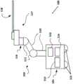
图1图示了根据本发明的实施例的机器人内窥镜系统;FIG. 1 illustrates a robotic endoscopy system according to an embodiment of the present invention;
图2A图示了根据本发明的实施例的机器人外科手术系统;2A illustrates a robotic surgical system according to an embodiment of the present invention;
图2B图示了其中朝向患者头部提供麻醉推车201的系统200的俯视图;Figure 2B illustrates a top view of the
图2C示出了图2A的系统200的视图;Figure 2C shows a view of the
图2D和图2E图示了示出了根据本发明的实施例的机器人外科手术系统的通用性的手臂202和204的备选布置;Figures 2D and 2E illustrate alternative arrangements of
图3A图示了根据本发明的实施例的具有多个虚拟轨的系统的俯视图;3A illustrates a top view of a system with multiple virtual tracks in accordance with an embodiment of the present invention;
图3B图示了具有附加的机器人手臂、相关的工具底座和工具的图3A的机器人外科手术系统的使用;3B illustrates use of the robotic surgical system of FIG. 3A with an additional robotic arm, associated tool base and tool;
图4图示了根据本发明的实施例的IDM和工具可互换的机器人外科手术系统;4 illustrates an IDM and a tool-interchangeable robotic surgical system according to an embodiment of the present invention;
图5A图示了根据本发明的实施例的联接到机器人系统中的机器人手臂的机构变换器接口的实现方式;5A illustrates an implementation of a mechanism changer interface coupled to a robotic arm in a robotic system according to an embodiment of the present invention;
图5B图示了图5A的凸(male)机构变换器接口502的备选视图;Figure 5B illustrates an alternate view of the male
图5C图示了联接到仪器设备操纵器用于与图5A和图5B的凸机构变换器接口502连接的互补的凹(female)机构变换器接口;5C illustrates a complementary female mechanism transducer interface coupled to an instrument manipulator for connection with the male
图5D图示了图5C的凹机构变换器接口508的备选视图;Figure 5D illustrates an alternate view of the female
图6图示了根据本发明的实施例的使用通过指向患者腹部的单个机器人手臂上的仪器接口连接的单端口腹腔镜仪器的机器人外科手术系统;6 illustrates a robotic surgical system using a single-port laparoscopic instrument connected through an instrument interface on a single robotic arm directed toward a patient's abdomen, according to an embodiment of the present invention;
图7图示了根据本发明的实施例的具有两套机器人子系统的机器人外科手术系统,每套机器人子系统具有一对手臂;7 illustrates a robotic surgical system having two robotic subsystems, each robotic subsystem having a pair of arms, according to an embodiment of the present invention;
图8A图示了根据本发明的实施例的具有带有单个机器人手臂的子系统的机器人外科手术系统,其中,显微镜工具通过仪器接口连接到机器人手臂;8A illustrates a robotic surgical system having a subsystem with a single robotic arm, wherein a microscope tool is connected to the robotic arm through an instrument interface, according to an embodiment of the present invention;
图8B图示了根据本发明的实施例的其中图8A的子系统801可以结合另一系统用来执行显微外科手术的机器人外科手术系统;8B illustrates a robotic surgical system in which the
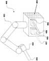
图9A图示了根据本发明的实施例的包括操纵器的机器人医疗系统的一部分;9A illustrates a portion of a robotic medical system including a manipulator according to an embodiment of the present invention;
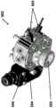
图9B图示了图9A中所公开的机器人医疗系统的备选视图;Figure 9B illustrates an alternate view of the robotic medical system disclosed in Figure 9A;
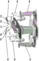
图10图示了根据本发明的实施例的具有张力传感装置的图9A,图9B的独立的驱动机构的备选视图;Figure 10 illustrates an alternative view of the independent drive mechanism of Figures 9A, 9B with a tension sensing device according to an embodiment of the present invention;
图11A从另一角度图示了图9A,图9B和图10的独立的驱动机构的剖视图;Figure 11A illustrates a cross-sectional view of the independent drive mechanism of Figures 9A, 9B and 10 from another angle;
图11B图示了根据本发明的实施例的结合内窥镜工具先前所讨论的独立的驱动机构的剖视图;11B illustrates a cross-sectional view of the separate drive mechanism previously discussed in connection with the endoscopic tool, in accordance with an embodiment of the present invention;
图12图示了根据本发明的实施例的具有来自内窥镜工具的拉线的先前所讨论的独立的驱动机构的备选视图。12 illustrates an alternative view of the previously discussed separate drive mechanism with a puller wire from an endoscopic tool in accordance with an embodiment of the present invention.
图13图示了根据本发明的实施例的示出了如何通过垂直于力定向的应变计测量水平力的概念图;13 illustrates a conceptual diagram showing how horizontal forces are measured by strain gauges oriented perpendicular to the force, in accordance with an embodiment of the present invention;
图14是根据本发明的实施例的可以结合图1的机器人系统100使用的内窥镜工具的图示;14 is an illustration of an endoscopic tool that may be used in conjunction with the
图15A,图15B,图15C,图16A和图16B通常图示了根据本发明的实施例的机器人驱动的内窥镜工具的各个方面;15A, 15B, 15C, 16A and 16B generally illustrate various aspects of a robotically driven endoscopic tool according to an embodiment of the present invention;
图17A至图17D图示了当筋被牵拉时,现有技术的柔性仪器如何展现不期望的“肌肉发育”现象;Figures 17A-17D illustrate how prior art flexible instruments exhibit an undesired phenomenon of "muscle development" when the tendon is pulled;
图17E至图17H图示了现有技术的柔性仪器如何在非线性通路中使用期间受到曲线对齐现象困扰;17E-17H illustrate how prior art flexible instruments suffer from curve alignment phenomena during use in nonlinear pathways;
图17I和图17J图示了根据本发明的实施例的如何通过提供螺旋状段基本上解决肌肉发育和曲线对齐现象;Figures 17I and 17J illustrate how muscle development and curve alignment phenomena are substantially addressed by providing helical segments in accordance with embodiments of the present invention;
图18图示了根据本发明的实施例的在管腔内具有轴向刚硬管的柔性内窥镜工具的结构;18 illustrates the structure of a flexible endoscopic tool with an axially rigid tube within a lumen according to an embodiment of the present invention;
图19图示了根据本发明的实施例的柔性内窥镜工具的管腔内的螺旋图案的结构;19 illustrates the structure of a helical pattern within a lumen of a flexible endoscopic tool according to an embodiment of the present invention;
图20A图示了根据本发明的实施例的来自机器人腔内系统的内窥镜工具;20A illustrates an endoscopic tool from a robotic intraluminal system according to an embodiment of the present invention;
图20B图示了图20A的内窥镜工具2000的备选视图;Figure 20B illustrates an alternate view of the
图21图示了根据本发明的实施例的内窥镜工具的远端;21 illustrates a distal end of an endoscopic tool according to an embodiment of the present invention;
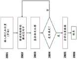
图22图示了根据本发明的实施例的构造具有螺旋管腔的内窥镜设备的方法的流程图;22 illustrates a flowchart of a method of constructing an endoscopic device having a helical lumen in accordance with an embodiment of the present invention;
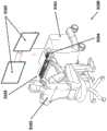
图23图示了根据本发明的实施例的用于制造柔性内窥镜的系统;Figure 23 illustrates a system for manufacturing a flexible endoscope according to an embodiment of the present invention;
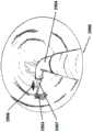
图24图示了根据本发明的实施例的用于制造具有螺旋牵拉管腔的内窥镜设备的专用鼻锥(nose cone);24 illustrates a dedicated nose cone for manufacturing an endoscopic device with a helical pull lumen in accordance with an embodiment of the present invention;
图25A和图25B图示了中心线坐标、直径测量值和解剖空间之间的关系;Figures 25A and 25B illustrate the relationship between centerline coordinates, diameter measurements, and anatomical space;
图26图示了根据本发明的实施例的表示解剖空间的计算机生成三维模型;26 illustrates a computer-generated three-dimensional model representing an anatomical space in accordance with an embodiment of the present invention;
图27图示了根据本发明的实施例的与电磁场发生器组合的利用电磁追踪器的机器人腔内系统;27 illustrates a robotic intracavity system utilizing an electromagnetic tracker in combination with an electromagnetic field generator in accordance with an embodiment of the present invention;
图28图示了根据本发明的实施例的用于配准的步骤的流程图;28 illustrates a flowchart of steps for registration according to an embodiment of the present invention;
图29A图示了根据本发明的实施例的解剖管腔内的内窥镜工具的远端;29A illustrates a distal end of an endoscopic tool within a dissection lumen according to an embodiment of the present invention;
图29B图示了根据本发明的实施例的在解剖管腔内的手术部位处使用的图29A的内窥镜工具;29B illustrates the endoscopic tool of FIG. 29A used at a surgical site within a dissection lumen, according to an embodiment of the present invention;
图29C图示了根据本发明的实施例的在解剖管腔内的手术部位处使用的图29B的内窥镜工具;Figure 29C illustrates the endoscopic tool of Figure 29B used at a surgical site within a dissection lumen, according to an embodiment of the present invention;
图30A图示了根据本发明的实施例的联接到解剖管腔内的远端柔性段的内窥镜工具;30A illustrates an endoscopic tool coupled to a distal flexible segment within a dissecting lumen according to an embodiment of the present invention;
图30B图示了根据本发明的实施例的在解剖管腔内的手术部位处使用的具有镊子工具的图30A的内窥镜工具;30B illustrates the endoscopic tool of FIG. 30A with a forceps tool for use at a surgical site within a dissection lumen in accordance with an embodiment of the present invention;
图30C图示了根据本发明的实施例的在解剖管腔内的手术部位处使用的具有激光设备的图30A的内窥镜工具;和30C illustrates the endoscopic tool of FIG. 30A with a laser device for use at a surgical site within an anatomical lumen in accordance with an embodiment of the present invention; and
图31图示了根据本发明的实施例的用于机器人腔内系统的命令控制台。31 illustrates a command console for a robotic intraluminal system in accordance with an embodiment of the present invention.
具体实施方式Detailed ways
尽管下文公开了某些优选实施例和示例,但是发明主题超出具体公开的实施例,扩展至其它备选实施例和/或使用、及其修改和等同物。因此,此处所附的权利要求的范围并不受下文所描述的特定实施例中的任一特定实施例限制。例如,在本文所公开的任何方法或过程中,方法或过程的动作或操作可以以任何合适顺序执行,并且不必限于任何特定公开顺序。各种操作可以以可以有助于理解某些实施例的方式依次被描述为多个分立操作;然而,描述顺序不应该被解释为暗示这些操作是顺序相关的。附加地,本文中所描述的结构、系统和/或设备可以被体现为集成部件或分离部件。While certain preferred embodiments and examples are disclosed below, the inventive subject matter extends beyond the specifically disclosed embodiments to other alternative embodiments and/or uses, modifications and equivalents thereof. Therefore, the scope of the claims appended hereto is not to be limited by any one of the specific embodiments described below. For example, in any method or process disclosed herein, the acts or operations of the method or process may be performed in any suitable order and are not necessarily limited to any particular disclosed order. Various operations may be described as multiple discrete operations, in turn, in a manner that may be helpful in understanding certain embodiments; however, the order of description should not be construed to imply that these operations are order dependent. Additionally, the structures, systems and/or devices described herein may be embodied as integrated components or separate components.
出于比较各种实施例的目的,对这些实施例的某些方面和优点进行描述。不必通过任何特定实施例实现所有这些方面或优点。因此,例如,各种实施例可以以实现或优化如在本文中所教导的一个优点或一组优点的方式来实现,而不必实现如可以在本文中所教导的或建议的其它方面或优点。For the purpose of comparing various embodiments, certain aspects and advantages of these embodiments are described. It is not necessary for all of these aspects or advantages to be realized by any particular embodiment. Thus, for example, various embodiments may be implemented in a manner that achieves or optimizes one advantage or group of advantages as taught herein without necessarily achieving other aspects or advantages as may be taught or suggested herein.
1.概述1 Overview
一种腔内外科手术机器人系统,提供给外科医生坐在人体工程学位置、并且控制机器人内窥镜工具到患者体内的所期望的解剖位置的能力,而无需笨拙的手臂运动和位置。An endoluminal surgical robotic system that provides a surgeon with the ability to sit in an ergonomic position and control a robotic endoscopic tool to a desired anatomical location within a patient without awkward arm movements and positions.
机器人内窥镜工具具有通过沿着其长度在至少两个点提供多个自由度轻易地导航人体内的管腔的能力。工具的控制点提供给外科医生当它在人体内的曲轴路径导航时,设备的显著更本能的控制。对于所有360度的滚动角度,工具的尖端还能够从0度关节连接到90度。The robotic endoscopic tool has the ability to easily navigate lumens in the human body by providing multiple degrees of freedom at at least two points along its length. The tool's control points provide the surgeon with significantly more instinctive control of the device as it navigates its crankshaft path within the body. The tool tip is also able to articulate from 0 to 90 degrees for all 360 degree roll angles.
外科手术机器人系统可以结合基于外部传感器和基于内部视觉两者的导航技术,以辅助医师引导到患者体内的所期望的解剖位置。导航信息可以在二维显示器件或三维显示器件中被传送。Surgical robotic systems can incorporate both external sensor-based and internal vision-based navigation techniques to assist the physician in guiding to the desired anatomical location within the patient. Navigation information can be conveyed in a two-dimensional display device or a three-dimensional display device.
2.系统部件2. System Components
图1是根据本发明的实施例的机器人内窥镜系统。如图1所示,机器人系统100可以包括具有至少一个机器人手臂(诸如手臂102)的系统推车101。该系统推车101可以与位于远端的命令控制台(未示出)通信。在实践中,该系统推车101可以被布置成提供对患者的进入,同时医师可以从命令控制台的舒适性出发控制该系统100。在一些实施例中,出于稳定性和对接近患者的考虑,该系统推车100可以被集成到手术台或床中。FIG. 1 is a robotic endoscopy system according to an embodiment of the present invention. As shown in FIG. 1 ,
在系统100内,手臂102可以被固定联接到包含多种支持系统(在一些实施例中,包括控制电子装置、电源和光源)的系统推车101。手臂102可以由多个连杆110和接头111形成,以使能够接近患者的手术区。系统推车103可以包含电源112、气动压力113、以及控制和传感器电子装置114(包括部件,诸如中央处理单元、数据总线、控制电路和存储器)及可以驱动手臂(诸如手臂102)的相关的致动器或电机。电源可以使用本领域技术人员已知的多种器件(诸如电线、齿轮头、空气室)从系统推车101传送到手臂102。系统推车101中的电子装置114还可以处理并且传输从命令控制台传达的控制信号。Within the
系统推车101还可以是移动的,如由车轮115所示。在一些实施例中,系统推车能够被推到患者附近的所期望的位置。系统推车101可以位于手术室中不同位置,以便适应空间需求并且有助于模块和仪器相对于患者的适当放置和运动。该能力使得将手臂能够定位在它们不干涉患者、医生、麻醉师或所选过程所需的任何支持外科手术设备的位置。在过程期间,带有仪器的手臂通过分离的控制设备经由用户控制协同工作,其可以包括具有触觉设备、操纵杆或定制垂饰(pendant)的命令控制台。The
3.机械手臂3. Robotic arm
手臂102的近端可以固定安装或联接到车101。机械手臂102包括每个手臂由至少一个接头(诸如接头111)连接的多个连杆110。如果机械手臂102是机器人的,则接头111可以包括一个或多个致动器,以便以至少一个自由度影响运动。手臂102作为一个整体优选具有三个以上的自由度。通过电线和电路的组合,每个手臂还可以将功率信号和控制信号从系统推车101传送到位于其末端的端部的仪器。The proximal end of the
在一些实施例中,手臂可以固定联接到带有患者的手术台。在一些实施例中,手臂可以联接到手术台的底座并且达到周围以接近患者。In some embodiments, the arm may be fixedly coupled to the operating table with the patient. In some embodiments, the arms may be coupled to the base of the operating table and reach around to access the patient.
在一些实施例中,机械手臂可能不是机器人驱动的。在那些实施例中,机械手臂包括使用制动器和平衡件的组合来保持手臂的位置在适当位置的连杆和调定接头。在一些实施例中,平衡件可以由气体弹簧或螺旋弹簧构造。制动器(诸如故障保险制动器)可以是机械的或机电的。在一些实施例中,手臂可以是重力辅助被动支撑手臂。In some embodiments, the robotic arm may not be robotically driven. In those embodiments, the robotic arm includes linkages and setting joints that use a combination of brakes and counterweights to maintain the position of the arm in place. In some embodiments, the counterweight may be constructed from a gas spring or a coil spring. Brakes, such as fail-safe brakes, may be mechanical or electromechanical. In some embodiments, the arm may be a gravity-assisted passive support arm.
在远端处,每个手臂可以通过机构变换器接口(MCI)(诸如116)联接到可移动的仪器设备操纵器(IDM)(诸如117)。在优选实施例中,MCI 116可以包含用来从手臂向IDM 117传递气动压力、电功率、电信号和光信号的连接器。在一些实施例中,MCI 116可以与紧定螺钉或底板连接一样简单。At the distal end, each arm may be coupled to a movable instrument device manipulator (IDM) (such as 117 ) through a Mechanism Inverter Interface (MCI) (such as 116 ). In a preferred embodiment, the
IDM 117可以具有用于操纵外科手术仪器的多种器件(包括直接驱动、谐波驱动、齿轮驱动、皮带和滑轮、或磁性驱动)。本领域技术人员应当理解,多种方法可以用来控制仪器设备上的致动器。The
在机器人系统内,MCI(诸如116)可以与多种过程特定的IDM(诸如117)互换。在该实施例中,IDM的可互换性允许机器人系统100执行不同过程。Within robotic systems, MCIs (such as 116 ) can be interchanged with various process-specific IDMs (such as 117 ). In this embodiment, the interchangeability of the IDM allows the
优选实施例可以使用在远端具有手腕的传感接头水平扭矩的机器人手臂,诸如Kuka AG’s LBR5。这些实施例具有带有七个接头的机器人手臂,而提供多余的接头以避免与接近手术视野的患者、其它机器人手臂、手术台、医疗人员或设备的潜在手臂碰撞,同时以同一姿势维持手腕,以便不中断正在进行的过程。本领域技术人员应当理解,具有至少三个自由度(并且更优选地六个或更多个自由度)的机器人手臂将落入本文中所描述的发明概念内,并且还应当理解,一个以上的手臂可以提供有附加模块,其中,每个手臂可以共同或单独地安装在一个或多个推车上。A preferred embodiment may use a robotic arm with a sensed joint level torque of the wrist at the distal end, such as Kuka AG's LBR5. These embodiments have a robotic arm with seven joints, while providing redundant joints to avoid potential arm collisions with patients, other robotic arms, operating tables, medical personnel, or equipment approaching the surgical field of view, while maintaining the wrist in the same posture, so as not to interrupt the ongoing process. It will be understood by those skilled in the art that a robotic arm with at least three degrees of freedom (and more preferably six or more degrees of freedom) will fall within the inventive concepts described herein, and it will also be understood that more than one The arms can be provided with additional modules, wherein each arm can be mounted together or individually on one or more carts.
4.虚拟轨配置4. Virtual track configuration
系统100中的手臂102可以以多种姿势进行布置用于多种过程。例如,结合另一机器人系统,系统100的手臂102可以被布置成对齐其IDM以形成有助于插入和操纵内窥镜工具118的“虚拟轨”。对于其它过程,手臂可以进行不同布置。因此,手臂在系统100中的使用提供了在其设计直接与特定医疗过程相关的机器人系统中未发现的灵活性。系统100的手臂提供了潜在的更大的冲程和装载。The
图2A图示了根据本发明的实施例的机器人外科手术系统200。系统200具有分别保持内窥镜工具底座206和208的第一手臂202和第二手臂204。工具底座206具有与其可操作地连接的可控制的内窥镜护套210。工具底座208具有与其可操作地连接的柔性内窥镜导引件212(endoscope leader)。Figure 2A illustrates a robotic
手臂202和204与工具底座206和208对齐,使得护套210的近端216远离导引件212的近端222,并且使得导引件212以在两个手臂之间180度的近似角度保持与护套210轴向对齐,从而产生“虚拟轨”,其中,该轨大致是平直的,或成180度。如稍后将要描述的,虚拟轨可以具有90度至180度之间的角度。在一个实施例中,导引件212滑动穿设于其中的护套210通过机器人插入通过例如患者211的口腔中的气管套管(未示出)并且进入患者211中,并且最终进入患者的支气管系统中,同时在插入和导航期间继续维持虚拟轨。手臂可以在控制台203(图2B)处根据医生(未示出)的控制相对于彼此轴向移动护套210和内窥镜212、并且进入或离开患者211。
实现了导航,例如,通过与导引件212一起前进护套210进入患者211,然后导引件212可以前进超出护套的远端213,然后护套210可以甚至与导引件212一起被携带,直至到达所期望的目的地。可以使用其它模式的导航,诸如但不限于使用通过导引件212的工作通道的引导线。医师可以使用任何数目的视觉引导模态或它们的组合,以帮助导航并且执行医疗过程,例如,荧光镜检查、视频、CT、MR等。导引件212的远端220然后被导航到手术部位并且工具通过导引件212内的纵向对齐的工作通道进行部署来执行所期望的过程。虚拟轨可以在导航过程和任何后续的手术过程期间被维持。如本领域技术人员应当了解的,可能需要工具或根本不需要工具的任意数目的备选过程可以使用通过护套滑动的柔性内窥镜来执行。Navigation is achieved, eg, by advancing the
图2B图示了其中朝向患者的头部提供麻醉推车201的系统200的俯视图。附加地,向控制护套210、内窥镜导引件212和相关的手臂202和204和工具底座206和208(参见图2A)提供具有用户接口的控制台203。2B illustrates a top view of the
图2C示出了图2A的系统200的斜视图。具有相关的护套210和导引件212的工具模块206和208附接到手臂202和204并且布置在180度的虚拟轨中。手臂被示出在单个推车上,其提供了附加紧凑性和机动性。如稍后将要讨论的,工具底座206和208具有用来张紧护套210和导引件212中的筋以操控它们各自远端的滑轮系统或其它致动系统。工具底座206和208可以提供用于护套和内窥镜的所期望的其它实用工具,诸如气动压力、电、数据通信(例如,用于视力)、机械致动(例如,电机驱动轴)等。这些实用工具可以从单独源或两者的组合通过手臂提供给工具底座。Figure 2C shows an oblique view of the
图2D和图2E图示了根据本发明的实施例的示出了机器人外科手术系统的通用性的手臂202和204的备选布置。在图2D中,可以延伸手臂202和204以定位仪器(包括护套210和导引件212)以与水平面夹角为75度进入患者211的口腔,同时仍维持180度的虚拟轨。如果需要,这可能在该过程期间以适应房间内的空间要求来进行。出于示范性目的而非限制,选择75度的角度。Figures 2D and 2E illustrate alternative arrangements of
图2E示出了根据本发明的实施例的其中工具底座206和208对齐以创建角度为90度的虚拟轨的手臂202和204的备选布置。在该实施例中,仪器(包括护套210和导引件212)以与水平面夹角为75度进入患者213口腔。对齐工具底座206和208,使得导引件212在进入患者213口腔之前在工具底座206处弯曲90度。为了便于导引件212的弯曲,刚性或半刚性结构(诸如管)可以用来确保护套210内的导引件212顺利延伸和缩回。护套210内的导引件212的延伸和缩回可以通过沿着由导引件212追踪的线性路径移动工具底座208靠近或远离工具底座206来控制。护套210的延伸和缩回可以通过沿着由护套210追踪的线性路径移动工具底座206靠近或远离患者213来控制。为了避免导引件212的非预期延伸和缩回,同时延伸或缩回护套210,还可以沿着平行于护套210的线性路径移动工具底座208。2E shows an alternative arrangement of
虚拟轨用于驱动刚性仪器和柔性仪器两者,并且特别地其中有伸缩要求的仪器。使用虚拟轨并不限于单个轨,而是可以由其中手臂协调动作以在执行一个或多个过程中维持各个虚拟轨的多个虚拟轨组成。Virtual rails are used to drive both rigid and flexible instruments, and in particular instruments where telescoping is required. The use of virtual tracks is not limited to a single track, but may consist of multiple virtual tracks in which the arms act in concert to maintain each virtual track during execution of one or more processes.
图3A图示了根据本发明的实施例的具有多个虚拟轨的系统的俯视图。在图3A中,机器人手臂302,304和306分别保持工具底座308,310和312。工具底座308和310可以可操作地联接到柔性工具314和工具316。工具314和工具316可以是遥控机器人控制的柔性内窥镜仪器。工具底座312可以可操作性地联接到双管腔护套318,其中,每个管腔接收工具314和316。手臂302和304各自可以维持具有机器人手臂306的虚拟轨,并且所有三个手臂的运动可以被协调,以维持虚拟轨并且相对于彼此和患者移动工具314,316和护套318。3A illustrates a top view of a system with multiple virtual tracks in accordance with an embodiment of the present invention. In Figure 3A,
图3B图示了具有附加的机器人手臂320和相关的工具底座322和工具324的图3A的机器人外科手术系统的使用。在该实施例中,护套325可以具有三个管腔。可替代地,护套325可以包括用来提供进入工具314,316和324的一个以上的护套。如应当理解的,增加或减少具有相关的模块和仪器的手臂的数目的能力允许外科配置的大数目和灵活性,其又允许重新考虑昂贵手臂和使用多个相对便宜的模块来以降低的成本实现很大通用性。FIG. 3B illustrates use of the robotic surgical system of FIG. 3A with an additional
因此,为了产生虚拟轨,可以利用多个手臂和/或平台。每个平台/手臂必须配准到其它平台/手臂,其可以由多个模态(包括视觉、激光、机械、磁或刚性附接)来实现。在一个实施例中,配准可以使用机械配准通过具有单个底座的多手臂设备来实现。在机械配准中,实施例可以基于它们相对于单个底座的位置、取向和放置配准手臂/平台放置、位置和取向。在另一实施例中,配准可以使用单独的底座配准和多个机器人手臂之间的“握手”由具有多个底座的系统来实现。在具有多个底座的实施例中,配准可以通过从不同底座一起触摸手臂并且基于(i)物理接触和(ⅱ)那些底座的相对位置计算位置、取向和放置来实现。在一些实施例中,配准目标可以用来匹配手臂相对于彼此的位置和取向。通过这样的配准,可以在相对于彼此的空间中计算手臂和仪器驱动机构。Thus, in order to generate the virtual track, multiple arms and/or platforms may be utilized. Each platform/arm must be registered to other platforms/arms, which can be achieved by multiple modalities including visual, laser, mechanical, magnetic or rigid attachment. In one embodiment, registration may be achieved with a multi-arm device with a single base using mechanical registration. In mechanical registration, embodiments may register arm/platform placement, position and orientation based on their position, orientation and placement relative to a single base. In another embodiment, registration may be achieved by a system with multiple bases using separate base registration and "handshake" between multiple robotic arms. In embodiments with multiple bases, registration may be achieved by touching the arms together from different bases and calculating position, orientation and placement based on (i) physical contact and (ii) the relative positions of those bases. In some embodiments, registration targets may be used to match the position and orientation of the arms relative to each other. With such a registration, the arm and instrument drive mechanisms can be calculated in space relative to each other.
5.机构变换器接口5. Mechanism converter interface
返回到图1,机器人外科手术系统100可以以一种方式被配置成提供多个外科手术系统配置,诸如通过改变IDM 117和工具118(还被称为端部执行器)。该系统可以包括手术室中不同位置或方便的附近位置处的一个或多个移动机器人平台。每个平台可以提供一些或所有功率、气动压力、照射源、数据通信电缆和用于联接到平台的机器人手臂的控制电子装置,并且模块也可以从这些实用工具中获取。可替代地,系统100可以具有安装在一个或多个移动车101上的多个手臂102,或手臂可以安装到地板以提供多个外科手术配置。Returning to FIG. 1 , the robotic
除了多个手臂和平台之外,一些实施例被设计成在多个模块或端部执行器机构之间轻易地进行交换。过程内的各种外科手术过程或步骤可能需要使用不同的模块和相关的仪器设置,例如,不同尺寸的护套和内窥镜组合之间的交换。互换性允许系统重新配置用于不同的临床过程或调整外科手术途径。In addition to multiple arms and platforms, some embodiments are designed to be easily interchanged between multiple modules or end effector mechanisms. Various surgical procedures or steps within the procedure may require the use of different modules and associated instrumentation settings, eg, the exchange between different sized sheaths and endoscope combinations. Interchangeability allows the system to be reconfigured for different clinical procedures or to adjust surgical approaches.
图4图示了根据本发明的实施例的IDM和工具可互换的机器人外科手术系统。外科手术系统400具有IDM 402和工具403附接到其的机械手臂401。附接到系统推车404的IDM405和406和相关的工具407和408可以被交换到机器人手臂401上或由不同的机器人手臂(未示出)拾取以单独与另一IDM和工具结合使用。每个IDM可以是专门的机电系统,其可以用来驱动各种类型的仪器和工具用于指定过程。为了驱动仪器,每个IDM可以包括独立的驱动系统,其可以包括电机。它们可以包含记录它们的校准和应用相关信息的传感器(例如,RFID)或存储器芯片。在新机构连接到机器人手臂之后,可以需要系统校准检查。在一些实施例中,IDM可以控制内窥镜护套或柔性内窥镜导引件。4 illustrates an IDM and a tool-interchangeable robotic surgical system in accordance with an embodiment of the present invention.
在图4中,系统400可以通过使用全局配准和传感器本身来交换IDM 402与IDM 405和406。在一些实施例中,IDM 406和408在配置有标识和接近传感器的预先确定的“扩展坞(docking station)”处被存储在系统推车404上。这些坞处的传感器可以利用技术,诸如RFID、光学扫描仪(例如,条形码)、EEPROM和物理接近传感器以配准并且标识哪些IDM“停靠”在扩展坞处。当机器人手臂401和IDM扩展坞驻留在系统推车404上,标识和接近传感器允许搁在扩展坞的IDM相对于(多个)机器人手臂进行配置。类似地,在单个系统推车上具有多个手臂的实施例中,多个手臂可以使用上文所讨论的配准系统和传感器的组合来访问扩展坞上的IDM。In FIG. 4,
图5图示了根据本发明的实施例的机器人系统中的机构变换器接口。图5A特别图示了根据本发明的实施例的联接到机器人系统中的机器人手臂的机构变换器接口的实现方式。如图5A所示,机器人手臂500的远端部分包括联接到“凸”机构变换器接口502的关节连接接头501。关节连接接头501提供相对于操纵被配置成联接到机器人手臂500的仪器设备机构(未示出)的附加的自由度。凸机构变换器接口502提供了凸连接器接口503,其提供了到IDM(未示出)上的互补的凹插座连接器接口的很强的物理连接。凸连接器接口503上的球形压痕物理地联接到IDM上的凹插座接口上的互补的压痕。当气动压力沿着机器人手臂500传送到凸机构变换器接口502时,可以延长球形压痕。凸机构变换器接口502还提供了用于将气动压力传递到IDM的连接504。附加地,机构变换器接口的这个实施例提供了对齐传感器505,其确保了凸机构变换器接口502及其互补的凹接口适当地对齐。5 illustrates a mechanism changer interface in a robotic system according to an embodiment of the present invention. Figure 5A particularly illustrates an implementation of a mechanism changer interface coupled to a robotic arm in a robotic system according to an embodiment of the present invention. As shown in FIG. 5A , the distal portion of the robotic arm 500 includes an articulation joint 501 coupled to a “male”
图5B图示了与机器人手臂500分离的凸机构变换器接口502的备选视图。如关于图5A所讨论的,凸机构变换器接口502提供凸缘状凸连接器接口503、气动连接器504和对齐传感器505。附加地,用于将电信号连接到IDM上的互补的接口的电性接口506(未示出)。FIG. 5B illustrates an alternate view of the male
图5C图示了联接到用于与图5A和图5B的凸机构变换器接口502连接的仪器设备操纵器的互补的凹机构变换器接口。如图5C所示,仪器设备操纵器507联接到被配置成连接到机器人手臂500上的凸机构变换器接口502的凹机构变换器接口508。凹机构变换器接口508提供被设计成联接到凸机构变换器接口502的凸缘状凸连接器接口503的凹插座接口509。凹插座接口509还提供了凹槽以夹紧凸连接器接口503上的球形凹痕。当施加气动压力时,延伸凸连接器503上的球形压痕,并且凸连接器503和插座接口509将IDM 507牢固地联接到机器人手臂500。互补的凹机构变换器接口508还提供有气动连接器510以接受从连接器504传送的气动压力。Figure 5C illustrates a complementary female mechanism changer interface coupled to an instrument manipulator for connection with the male
图5D图示了图5C的凹机构变换器接口508的备选视图。如前面所讨论的,互补的机构变换器接口508包含插座接口509、用于与机器人手臂500上的机构变换器接口502进行接口的气动连接器510。另外,机构变换器接口508还提供了用于向机构变换器接口502中的模块506传输电信号(功率、控制、传感器)的电性模块511。Figure 5D illustrates an alternate view of the female
图6,图7,图8A和图8B图示了可以使用图4的系统400进行操作的可互换的模块。图6图示了使用通过指向患者605的腹部604的单个机器人手臂603上的仪器接口602所连接的单端口腹腔镜仪器601的本发明的实施例。FIGS. 6 , 7 , 8A and 8B illustrate interchangeable modules that may operate using the
图7图示了具有两套机器人子系统701和704的本发明的实施例,每套机器人子系统分别具有一对手臂702,703和705,706。通过手臂702,703,705,706的远端处的仪器接口所连接的分别是腹腔镜仪器707,708,709,710,所有仪器一起工作以在单独患者711中执行过程。Figure 7 illustrates an embodiment of the invention having two sets of
图8A图示了具有带有单个机器人手臂802的子系统801的本发明的实施例,其中,显微镜工具804通过仪器接口803连接到机器人手臂802。在一些实施例中,显微镜工具804可以结合医师806所使用的第二显微镜工具805用来帮助可视化患者807的手术区域。FIG. 8A illustrates an embodiment of the invention having a
图8B图示了本发明的实施例,其中,图8A的子系统801可以结合子系统808用来执行显微外科手术。子系统808提供手臂809和810,每个手臂具有通过各相应手臂上的仪器接口所连接的显微外科手术工具811和812。在一些实施例中,一个或多个手臂可以捡起和交换表内的工具或者机器人手臂到达范围之内的其它合适保持机构,诸如扩展坞。Figure 8B illustrates an embodiment of the present invention in which subsystem 801 of Figure 8A may be used in conjunction with
在一些实施例中,机构变换器接口可以是用来紧固相关的IDM的简单螺钉。在其它实施例中,机构变换器接口可以是具有电连接器的螺栓板。In some embodiments, the mechanism changer interface may be a simple screw used to fasten the associated IDM. In other embodiments, the mechanism changer interface may be a bolt plate with electrical connectors.
6.仪器设备操纵器(IDM)6. Instrument Device Manipulator (IDM)
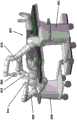
图9A图示了根据本发明的实施例的包括操纵器的机器人医疗系统的一部分。系统900包括机器人手臂901、关节连接接口902、仪器设备操纵器(“IDM”)903和内窥镜工具904的局部视图。在一些实施例中,机器人手臂901可能只是具有多个接头和连杆的较大的机器人手臂中的连杆。关节连接接口902将IDM 903联接到机器人手臂901。除了联接之外,关节连接接口902还可以向手臂901和IDM903传递气动压力、功率信号、控制信号和反馈信号,并且从手臂901和IDM 903传递气动压力、功率信号、控制信号和反馈信号。9A illustrates a portion of a robotic medical system including a manipulator according to an embodiment of the present invention.
IDM 903驱动并且控制内窥镜工具904。在一些实施例中,IDM 903使用经由输出轴传输的角运动以便控制内窥镜工具904。如稍后所讨论的,IDM 903可以包括齿轮头、电机、旋转编码器、功率电路、控制电路。The
内窥镜工具904可以包括具有远端尖端和近端的轴909。用于接收控制信号并且从IDM 903驱动的工具底座910可以联接到轴909的近端。通过由工具底座910所接收的信号,可以基于经由输出轴905,906,907和908(参见图9B)向内窥镜工具904的工具底座910传输的角运动来控制、操纵并且指引内窥镜工具904的轴909。
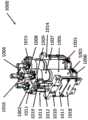
图9B图示了图9A所公开的机器人医疗系统的备选视图。在图9B中,内窥镜工具904已经从IDM 903中去除,以显露输出轴905,906,907和908。附加地,去除IDM 903的外皮/壳显露了IDM顶盖911下面的部件。Figure 9B illustrates an alternate view of the robotic medical system disclosed in Figure 9A. In FIG. 9B ,
图10图示了根据本发明的实施例的具有张力检测装置的图9A,图9B的独立的驱动机构的备选视图。在IDM 903的剖视图1000中,平行驱动单元1001,1002,1003和1004是IDM903中在结构上是最大的部件。在一些实施例中,从近端到远端,驱动单元1001可以包括旋转编码器1006、电机1005和齿轮头1007。驱动单元1002,1003和1004可以被类似地构造,即,包括顶盖911下面的电机、编码器和齿轮头。在一些实施例中,在驱动单元中使用的电机是无刷电机。在其它实施例中,电机可以是直流伺服电机。Figure 10 illustrates an alternative view of the separate drive mechanism of Figures 9A, 9B with a tension detection device according to an embodiment of the present invention. In the
旋转编码器1006监测并且测量电机1005的驱动轴的角速度。在一些实施例,旋转编码器1006可以是冗余旋转编码器。在于2014年8月14日提交的美国临时专利申请号62/037,520中公开了适当的冗余编码器的结构、能力和使用,其全部内容通过引用并入本文。The
由电机1005生成的扭矩可以通过联接到电机1005的转子的轴传输到齿轮头1007。在一些实施例中,齿轮头1007可以附接到电机1005,以便以转动速度为代价增加电机输出的扭矩。由齿轮头1007生成的增加的扭矩可以被传输到齿轮头轴1008中。类似地,驱动单元1002,1003和1004通过齿轮头轴906,907和908将它们各自的转矩传输出。The torque generated by the
每个单独的驱器单元可以联接到其远端的电机安装件和朝向其近端的应变计安装件。例如,驱动单元1001的远端可以被夹持到电机安装件1009和应变计安装件1001。类似地,驱动单元1002可以被夹持到电机安装件1011,同时两者还均被夹持到应变计安装件1010。在一些实施例时,电机安装件由铝构造以减轻重量。在一些实施例中,应变计安装件可以粘附到驱动单元的一侧。在一些实施例中,应变计安装件可以由铝构造以减轻重量。Each individual driver unit may be coupled to a motor mount at its distal end and a strain gauge mount towards its proximal end. For example, the distal end of
电应变计1012和1013被封装并且焊接到应变计安装件1010并且分别使用螺钉附接到电机安装件1009和1011。类似地,接近驱动单元1003和1004的一对应变计(未示出)被封装并且焊接到应变计安装件1014并且分别使用螺钉附接到电机安装件1015和1016。在一些实施例中,电应变计可以使用侧螺钉相对于它们各自的电机安装件保持在适当位置。例如,侧螺钉1019可以被插入到电机安装件1009以保持应变计1012在适当位置。在一些实施例中,可以垂直布置电应变计中的应变计布线以便检测驱动单元中的任何垂直应变或柔曲,其可以由相对于应变计安装件(1010)的电机安装件(1009,1011)测量为水平位移。
应变计布线可以被路由到应变计安装件上的电路。例如,应变计1012可以被路由到可以被安装在应变计安装件1010上的电路板1017。类似地,应变计1013可以被路由到还可以被安装在应变计安装件1010上的电路板1018。在一些实施例中,电路板1017和1018可以分别处理或放大来自应变计1012和1013的信号。电路板1017和1018到应变计1012和1013的紧密接近帮助降低信噪比以获得更准确的读数。Strain gage wiring can be routed to circuitry on the strain gage mount. For example,
图11A从另一角度图示了图9A,图9B和图10的独立的驱动机构的剖视图。如图11A所示,外壳/皮1101的一部分已经被切除以显露IDM 903的内部结构。如前面所讨论的,驱动单元1001包括电机1005、旋转编码器1006和齿轮头1007。驱动单元1001可以联接到电机安装件1009并且穿过顶盖911,通过该顶盖可以以所期望的角速度和扭矩驱动输出轴905。电机安装件1009可以使用侧螺钉联接到垂直对齐的应变计1012。除了联接到电机安装件1009之外,应变计1012可以被封装到应变计安装件1010中。在一些实施例中,输出轴905包括齿轮头轴上的迷宫式密封件。11A illustrates a cross-sectional view of the independent drive mechanism of FIGS. 9A , 9B and 10 from another angle. As shown in FIG. 11A , a portion of the housing/
图11B图示了根据本发明的实施例的结合内窥镜工具先前所讨论的独立的驱动机构的剖视图。如图11B所示,安装在IDM 903上的内窥镜工具904包含沿纵向与IDM 903的输出轴对齐的滑轮,诸如可以与输出轴905同心的滑轮1102。滑轮1102可以被容纳在工具底座910内的精密切割室1103内部,使得滑轮1102可能无法刚性固定在室1103内部,而是“浮动”在室1103中的空间内。11B illustrates a cross-sectional view of the separate drive mechanism previously discussed in connection with the endoscopic tool, in accordance with an embodiment of the present invention. As shown in FIG. 11B ,
滑轮1102的花键(spline)被设计成使得它们与输出轴905上的花键对齐并且使用输出轴905上的花键锁定。在一些实施例中,花键被设计成使得内窥镜工具可能只有单个取向与IDM 903对齐。尽管花键确保了滑轮1102与输出轴905同心对齐,但是滑轮1102还可以结合使用磁铁1104定位并且轴向保持与输出轴905对齐的浮动滑轮1102。锁定到对齐中,输出轴905和滑轮1102的转动张紧内窥镜器械904内的拉线,从而产生轴909的关节连接。The splines of the
图12图示了从根据本发明的实施例的具有来自内窥镜工具的拉线的先前所讨论的独立的驱动机构的备选视图。在一些实施例中,内窥镜工具可以使用拉线以便关节连接并且控制轴。在那些实施例中,这些拉线1201,1202,1203和1204可以分别由IDM 903的输出轴905,906,907和908张紧或松动。因此,拉线可以经由IDM 903中的控制电路通过机器人进行控制。12 illustrates an alternative view from the previously discussed separate drive mechanism with a puller wire from an endoscopic tool in accordance with an embodiment of the present invention. In some embodiments, the endoscopic tool may use pull wires to articulate and control the shaft. In those embodiments, the
正如输出轴905,906,907和908通过角运动沿着拉线1201,1202,1203和1204传递力一样,拉线1201,1202,1203和1204将力传递回到输出轴并且因此到电机安装件和驱动单元。例如,指引远离输出轴的拉线中的张力会产生牵拉电机安装件1009和1011的力。因为应变计均联接到电机安装件1009和1011并且封装在应变计安装件1010中,所以该力可以由应变计(诸如1012和1013)测量。Just as
图13图示了根据本发明的实施例的示出了如何可以由垂直于力定向的应变计测量水平力的概念图。如图1300所示,可以指引力1301远离输出轴1302。当输出轴1302联接到电机安装件1303时,力1301产生电机安装件1303的水平位移。当电机安装件1303使应变计1304在力1301的方向上柔曲(导致应变)时,联接到电机安装件1303和地面1305两者的应变计1304从而可能经历应变。应变量可以被测量为应变计1304的尖端的水平位移与应变计1304的整体水平宽度的比值。因此,应变计1304可以最终测量施加在输出轴1302上的力1301。13 illustrates a conceptual diagram showing how horizontal forces may be measured by strain gauges oriented perpendicular to the force, in accordance with an embodiment of the present invention. As shown in diagram 1300,
在一些实施例中,组件可以包括用来测量仪器设备操纵器903(诸如倾斜计或加速度计)的取向的设备。结合应变计,来自设备的测量值可以用来校准来自应变计的读数,因为应变计可能对从它们相对于地面的取向产生的重力载荷效应敏感。例如,如果仪器设备操纵器903在其一侧上被定向,则驱动单元的重量可以在电机安装件上产生即使应变不能从输出轴上的应变产生,也可以被传输到应变计的应变。In some embodiments, the assembly may include a device to measure the orientation of an
在一些实施例中,来自应变计电路板的输出信号可以联接到另一电路板用于处理控制信号。在一些实施例中,功率信号从处理控制信号的电路板被路由到另一电路板上的驱动单元。In some embodiments, the output signal from the strain gauge circuit board may be coupled to another circuit board for processing control signals. In some embodiments, power signals are routed from a circuit board that processes control signals to a drive unit on another circuit board.
如前面所讨论的,驱动单元1001,1002,1003和1004中的电机最终驱动输出轴,诸如输出轴905,906,907和908。在一些实施例中,输出轴可以使用无菌屏障进行增强以防止流体进入仪器设备操纵器903。在一些实施例中,屏障可以利用输出轴周围的迷宫式密封(图11A的1105)以防止流体进入。在一些实施例中,齿轮头轴的远端可以用输出轴覆盖以向工具传输扭矩。在一些实施例中,输出轴可以包覆在钢帽中以减少磁导。在一些实施例中,输出轴可以被夹持到齿轮头轴以辅助扭矩的传递。As previously discussed, the motors in
仪器设备机构903还可以覆盖有壳或皮,诸如外壳/皮1101。除了造型美观之外,壳在手术期间(例如,在医疗过程期间)提供了流体进入保护。在一些实施例中,壳可以使用浇铸聚氨酯构造用于电磁屏蔽、电磁兼容性和静电放电保护。
在本发明的实施例中,单独张紧的那些输出轴的每个输出轴可以在利用可操控导管技术的内窥镜工具中牵拉线。拉线中的张力可以被传输到输出轴905,906,907和908并且向下传输到电机安装件,诸如电机安装件1009和1011。In an embodiment of the invention, each of those output shafts that are individually tensioned can pull a wire in an endoscopic tool utilizing steerable catheter technology. Tension in the pull wires can be transmitted to
7.内镜工具设计7. Endoscopic tool design
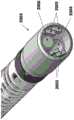
在优选实施例中,图1的机器人系统100可以驱动针对腔内过程而定制的工具,诸如内窥镜工具118。图14是根据本发明的实施例的可以结合图1的机器人系统100使用的内窥镜工具的图示。内窥镜工具1400可以布置在纵向对齐的嵌套管状本体(被称为“护套”和“导引件”)周围。护套1401(具有较大外径的管状工具)可以包括近端护套段1402、远端护套段1403和中央护套管腔(未示出)。通过在护套底座1404中接收的信号,远端护套段1403可以在操作者所期望的方向上进行关节连接。嵌套在护套1401内的可以是具有较小外径的导引件1405。导引件1405可以包括近端导引件段1406和远端导引件段1407、和中央工作通道。类似于护套底座1404,导引件底座1408基于传达到通常来自IDM(例如,图9A的903)的导引件底座1408的控制信号来控制远端导引件段1407的关节连接。In a preferred embodiment, the
护套底座1404和导引件底座1408两者均具有类似的驱动机构,护套1401和导引件1405内的控制筋锚固到该驱动机构。例如,护套底座1404的操纵可以对护套1401中的筋放置拉伸载荷,在其中以受控形式导致远端护套段1403的偏转。类似地,导引件底座1408的操纵可以对导引件1405中的筋放置拉伸载荷以导致远端导引件段1407的偏转。护套底座1404和导引件底座1408还可以包含用于从IDM向护套1401和导引件1404路由气动压力、电功率、电信号或光信号的联轴器。Both the
护套1401和导引件1405内的控制筋可以通过关节连接段被路由到位于关节连接段远端的锚具。在优选实施例中,护套1401和导引件1405内的筋可以由通过不锈钢线圈(诸如盘管)路由的不锈钢控制筋构成。本领域技术人员应当理解,其它材料还可以用于筋,诸如芳纶、钨和碳纤维。对这些筋放置载荷导致护套1401和导引件1405的远端段以可控方式偏转。沿着护套1401和导引件1405内的筋的长度包括盘管可以将轴向压缩传递回到载荷原点。The control tendons within the
使用多个筋,内窥镜工具1400具有通过沿着其长度在两个点处(远端护套段1403和远端导引件段1407)提供多个控制自由度(每个与单独筋相对应)轻易地导航人体内的管腔的能力。在一些实施例中,高达四个筋可以用于护套1401和/或导引件1405,从而提供高达所组合的八个自由度。在其它实施例中,可以使用高达三个筋,从而提供高达六个自由度。Using multiple ribs, the
在一些实施例中,护套1401和导引件1405可以被卷绕360度,从而提供了甚至更多的工具灵活性。因为在人体内导航曲折路径,所以卷绕角、多个关节连接度和多个关节连接点的组合提供给医师对设备的本能控制的显著改善。In some embodiments, the
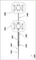
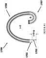
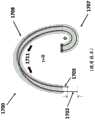
图15A,图15B,图15C,图16A和图16B通常图示了根据本发明的实施例的图2的机器人驱动的内窥镜工具(诸如护套210和导引件212)的各个方面。图15A图示了具有带有远端1501和近端1502和在这两个端部之间运转的管腔1503的护套1500的内窥镜工具。管腔1503的尺寸可以被设置成滑动地接收柔性内窥镜(诸如图16的导引件1600)。护套1500具有带有在护套1500的壁1504的长度内部运转的筋1505和1506的壁1504。筋1505和1506可以滑动地穿过壁1504中的导管1507和1508,并且在远端1501终止。在一些实施例中,筋可能可以由钢形成。适当张紧筋1505可以将远端1501朝向导管1507压缩,同时最小化螺旋状段1510的弯曲。类似地,适当张紧筋1506可以将远端1501朝向导管1508压缩。在一些实施例中,管腔1503可能与护套1500不同心。15A, 15B, 15C, 16A, and 16B generally illustrate various aspects of the robotically driven endoscopic tool of FIG. 2, such as
图15A的护套1500的筋1505和1506和相关的导管1507和1508优选地不沿着护套1500的整个长度平直运转,但是沿着螺旋状段1510在护套1500周围螺旋,然后沿着远端段1509纵向平直运转(即,大致平行于中性轴线)。应当理解,螺旋状段1510可以从沿着护套1510向近端延伸的远端段1509的近端开始,并且可以在任何所期望的或可变俯仰的任何所期望的长度处终止。螺旋状段1510的长度和俯仰可以基于护套1500的将轴的所期望的灵活性和螺旋状段1510中的增加的摩擦考虑在内的所期望的特性进行确定。当不在螺旋状段(诸如内窥镜1500的近端段和远端段)时,筋1505和1506可以大致平行于护套1500的中央轴线1511运转。
在一些实施例中,筋导管彼此可以成九十度夹角(例如,3点钟、6点钟、9点钟和12点钟)。在一些实施例中,筋可以彼此间隔开120度,例如,总共三个筋。在一些实施例中,筋可以不等距隔开。在一些实施例中,它们可以朝向中央管腔的一侧。在一些实施例中,筋计数可以不同于三个或四个。In some embodiments, the tendon conduits may be at a ninety degree angle to each other (eg, 3 o'clock, 6 o'clock, 9 o'clock, and 12 o'clock). In some embodiments, the ribs may be spaced 120 degrees from each other, eg, three ribs in total. In some embodiments, the ribs may not be equally spaced. In some embodiments, they may face one side of the central lumen. In some embodiments, the rib count may be different from three or four.
图15B示出了出于澄清非螺旋状段1509和可变俯仰螺旋状段1510之间的区别的目的只具有一个筋的护套1500的实施例的三维图示。尽管可以使用一个筋,但是可以优选的是使用多个筋。图15C示出了沿着远端段1509和可变俯仰螺旋状段1510延伸的四个筋的护套1500的实施例的三维图示。FIG. 15B shows a three-dimensional illustration of an embodiment of a
图16A图示了具有远端1601和近端1602的内窥镜导引件1600,其尺寸被设置成滑动地驻留在图15的护套1500内。导引件1600可以包括穿过它的至少一个工作通道1603。护套1500的近端1502和导引件1600的近端1602分别可操作地连接到图2的工具底座206和208。筋1604和1605分别滑动穿过壁1608中的导管1606和1607并且在远端1601终止。FIG. 16A illustrates an
图16B图示了具有成像1609(例如,CCD或CMOS相机、成像纤维束的终端等)、光源1610(例如,LED、光纤等)并且可以包括至少一个工作通道开口1603的导引件1600(示例性实施例)的远端1601。其它通道或操作电子装置1606可以沿着导引件1600提供以在远端处提供各种已知能力,诸如到相机的布线、吹气、吸入、电力、光纤、超声换能器、EM传感和OCT传感。FIG. 16B illustrates a guide 1600 (example) having an imaging 1609 (eg, CCD or CMOS camera, termination of an imaging fiber bundle, etc.), a light source 1610 (eg, LED, fiber optic, etc.), and may include at least one working channel opening 1603 (example example) of the
在一些实施例中,导引件1600的远端1601可以包括用于插入工具的“口袋”,诸如上文所公开的那些。在一些实施例中,该口袋可以包括用于对工具进行的控制的接口。在一些实施例中,可以存在缆线(诸如电缆或光缆)以便与接口通信。In some embodiments, the
在一些实施例中,图15A的护套1500和图16A的导引件1600两者均可以具有机器人控制的可操控远端。启用该控制的护套1500和导引件1600的结构可以基本上相同。因此,对于护套1500的构造的讨论将局限于护套1500的构造,并且应当理解,相同原则适用于导引件1600的结构。In some embodiments, both the
因此,来自图16A的导引件1600的筋1604和1605和相关的导管1606和1607不是沿着导引件1600的长度纵向平直(即,大致平行于中性轴线)运转,而是沿着导引件1600的不同部分进行螺旋。如护套1500中的螺旋状筋和导管一样,导引件1600的螺旋状筋可以基于导引件的把轴的所期望的灵活性和螺旋状段的增加摩擦考虑在内的所期望的特性来确定。当不在螺旋状段中时,筋1604和1605大致平行于导引件1600的中心轴线运转。Thus, the
如下文更充分描述的螺旋状段可以帮助隔离对远端段的弯曲,同时最大限度地减少沿着远端段近端的轴出现的任何弯曲。在本发明的一些实施例中,护套1500和导引件1600中的导管的螺旋俯仰可以沿着螺旋状段的长度变化,其如下面更充分描述的将更改轴的刚度/刚性。A helical segment, as described more fully below, can help isolate curvature to the distal segment while minimizing any curvature that occurs along the axis proximal to the distal segment. In some embodiments of the invention, the helical pitch of the catheter in
护套1500和导引件1600中的螺旋状导管和螺旋状筋的使用呈现了比没有螺旋状导管的先前柔性仪器的显著优点,特别地,当在解剖结构中导航非线性通路时。当导航弯曲通路时,可以优选的是,护套1500和导引件1600在其长度的大部分上保持柔性,并且具有可控制可操控的远端段,同时还有远端弯曲段近端的仪器的最小二次弯曲。在先前柔性仪器中,张紧筋以便关节连接远端导致沿着柔性仪器的整个长度的不希望的弯曲和扭转,其可以被分别被称为“肌肉发育”和“曲线对齐”。The use of helical conduits and helical tendons in
图17A至图17D图示了当筋被牵拉时,现有技术的柔性仪器如何展示不受欢迎的“肌肉发育”现象。在图17A中的,先前内窥镜1700沿着内窥镜1700的长度可以具有大致平行于中性轴线1701运转的四个筋或控制线。仅在横截面中示出了行进穿过轴壁中的导管1704和1705(还被称为控制管腔)的筋1702和1703,其每个被固定连接到内窥镜1700远端上的控制环1706。内窥镜1700可以被有意地设计成具有弯曲段1707和轴1708。在一些柔性仪器中,轴1708可以包括较硬材料,诸如加强筋。Figures 17A-17D illustrate how prior art flexible instruments exhibit the undesirable phenomenon of "muscle development" when the tendon is pulled. In FIG. 17A , the
图17B图示了弯曲段1707的理想化关节连接。通过牵拉或对筋1703施加张力,只有远端弯曲段1707的关节连接产生由φ表示的数量,其中,筋1702和1703的近端处的长度差可能为f(φ)。与此相反,轴1708沿着中性轴线1701可能保持平直。这可以通过具有刚度显著比远端区1707高的近端区1708来实现。FIG. 17B illustrates an idealized articulation of
图17C图示了从张紧筋1703产生的真实世界。如图17C所示,当张力非局部化时,牵拉筋1703沿着轴的整个长度产生压缩力。在理想化情况下,沿着中性轴线1701的是筋1703,整体压缩载荷可能同样沿着中心轴线传输并且大多数或所有的弯曲可能发生在弯曲段1707。然而,在筋1703沿着轴1708的外周(诸如在内窥镜1700中)运转时,轴向载荷在沿着中性轴线产生累积力矩的中性轴线的相同径向取向上传递出中性轴线1701。这导致轴1708弯曲(被描绘为θ),其中,轴1708的弯曲将在与弯曲段1707的弯曲相同的方向上。当内窥镜1700和远端弯曲段1707弯曲时,沿着导管1704和导管1705的长度必须改变。当筋1703需要缩短并且筋1702需要延长时,从近端延伸的筋1702和1703的数量为f(φ,θ)。其中轴1707和远端弯曲段1708从牵拉筋1703弯曲的这种现象被称为“肌肉发育”。FIG. 17C illustrates the real world generated from tension bars 1703 . As shown in Figure 17C, when the tension is non-localized, the tension bars 1703 create a compressive force along the entire length of the shaft. Ideally, along the
图17D图示了有助于三维的肌肉发育的力。如图17D所示,沿着内窥镜1700张紧筋1703会导致筋1703朝向仪器的一侧定向地施加力1712。力1712的方向反映了筋1703中的张力导致筋寻求遵循从远端弯曲段1707的尖端到轴1708的底座的直线,即,如由虚线1713所表示的最低能态。如应当理解的,如果轴1708是刚性的(即,不易在力的作用下弯曲),则只有远端弯曲段1707会弯曲。然而,在许多应用中,不希望的是,使轴的刚性完全与远端不同以充分最小化肌肉发育现象。Figure 17D illustrates the forces that contribute to three-dimensional muscle development. As shown in Figure 17D, tensioning the
图17E至图17H图示了先前柔性仪器在用于非线性通路期间如何受到曲线对齐现象困扰。图17E示出了由沿着内窥镜1700的轴1708具有弯曲τ表示的非线性路径内的静止的先前柔性内窥镜1700。例如,这可能由导航越过支气管管腔的弯曲的仪器产生。由于非线性弯曲,内窥镜1700中的筋1702和1703需要在近端延长或缩短一长度以适应非线性弯曲,其长度由F(τ)表示。延伸和压缩力存在于弯曲的顶部和底部处的管腔/导管上,如分别由箭头1709(延伸力)和1710(压缩力)描绘。因为沿着弯曲顶部的距离比中性轴线长,并且沿着弯曲内侧的距离比中性轴线短,所以这些力存在。17E-17H illustrate how previous flexible instruments suffer from curve alignment phenomena during use in nonlinear pathways. FIG. 17E shows a stationary, previously
图17F图示了在与弯曲τ相同的方向上关节连接内窥镜1700的远端弯曲段1707的力学,其中,一个可能牵拉筋1703。这沿着柔性仪器(如先前所描述的)的长度产生压缩力,并且筋1703还对其所穿过的非线性导管施加向下力,其对先前由解剖曲折压缩的轴1708施加附加压缩。因为这些压缩引线是附加的,所以轴1708将进一步在与远端弯曲段1707相同的方向上弯曲。沿着非线性导管的附加压缩力可能是不希望的,原因是:(i)其可能无意对解剖结构强加柔性仪器;(ii)当他/她应当能够“假设”解剖结构正在管控仪器轴的轮廓时,因为他/她必须不断地监控轴正在做什么,所以伤害的可能性使操作者分心;(ⅲ)弯曲仪器效率低;(ⅳ)期望隔离远端段处的弯曲以有助于可预测性和可控制性(即,理想仪器具有根据命令弯曲并且不是解剖非线性路径的函数的弯曲段);以及(v)它迫使用户牵拉筋1103不可预知的附加长度(φ+θ+τ)。17F illustrates the mechanics of articulating the distal
图17G图示了其中期望关节连接与弯曲τ相对的远端的场景,同时需要牵拉筋1702。牵拉筋1702沿着曲线的顶部施加压缩载荷1711,其与如图17E所示的静止状态下的弯曲的延伸载荷相反。筋1702试图回到其最低能态,即,其中,压缩载荷1711搁置在弯曲τ的内部,并且使轴1708在箭头1712的方向上转动,以使筋1702搁置在弯曲τ内部。如图17H所示,来自筋1702上的张力的转动1712移动压缩载荷1711以返回到弯曲内部,并且使远端弯曲段1707在弯曲τ的方向上回卷,从而产生与所预期的关节连接相对的关节连接。筋1702上的张力以及随之而来的转动1712在实践中将内窥镜1700返回至与图17F相同的状态。其中远端关节连接朝向弯曲τ回卷被称为现象“曲线对齐”。应当理解,曲线对齐由导致肌肉发育的相同的力产生,其中,这些力在肌肉发育的情况下产生不期望的侧向运动和在曲线对齐的情况下产生不期望的转动运动。应该注意,肌肉发育和曲线对齐的理论的讨论不是通过限制的方式提供,并且本发明的实施例不以任何方式受限于该解释。FIG. 17G illustrates a scenario in which it is desired to articulate the distal end opposite bending τ, while a
图17I和图17J图示了肌肉发育和曲线对齐现象如何通过在本发明的实施例中提供螺旋状段(诸如图15的1510)基本上得以解决。如图17I所示,螺旋内窥镜1700周围(诸如在图15的螺旋状段1510中)的控制管腔径向分布来自内窥镜1700周围的单个筋1715的压缩载荷1714。因为张紧后的筋1715对称地在中性轴线周围的多个方向上传输压缩载荷1714,所以对轴施加的弯曲力矩还在轴的纵向轴线周围进行对称地分布,其平衡并且抵消相反的压缩力和拉伸力。弯曲力矩的分布产生最少的净弯曲和转动力,从而产生如由虚线1816表示的纵向平行于中性轴线的最低能态。这消除或基本上减少了肌肉发育和曲线对齐现象。Figures 17I and 17J illustrate how muscle development and curve alignment phenomena are substantially addressed by providing helical segments such as 1510 of Figure 15 in embodiments of the present invention. As shown in FIG. 17I , the control lumen around the helical endoscope 1700 (such as in the
在一些实施例中,可以变化螺旋俯仰以影响螺旋状段的磨擦和刚度。例如,螺旋状段1510可以更短,以允许更大的非螺旋状段1509,从而产生更大关节连接段和可能更少摩擦。In some embodiments, the pitch of the helix can be varied to affect the friction and stiffness of the helical segment. For example, the
然而,螺旋控制管腔产生几个权衡。螺旋控制管腔仍然不能防止来自筋中的张力的屈曲。附加地,尽管肌肉发育大大降低,但是“盘旋”(将轴弯曲成螺旋形,由于筋中的张力而导致的弹簧状图案)非常常见。而且,当筋行进穿过管腔更长距离时,螺旋控制管腔需要补偿附加摩擦力。However, the helical control lumen creates several tradeoffs. The helical control lumen still does not prevent buckling from tension in the tendon. Additionally, although muscle development is greatly reduced, "circling" (bending the shaft into a helix, a spring-like pattern due to tension in the tendons) is very common. Also, the helical control lumen needs to compensate for additional friction as the tendon travels longer distances through the lumen.
图18图示了根据本发明的实施例的在管腔内具有轴向刚硬管的柔性内窥镜工具的结构。在图18中,内窥镜工具的一段具有带有在轴1800周围以螺旋图案缠绕的拉线1802的单个管腔1801。在管腔内部,轴向刚硬管1803在拉线1802周围和管腔1801内“浮动”。在轴1800的螺旋部分的开始和末端锚固的浮动管1803延伸并且压缩以响应于拉线1802中的张力和外部曲折,从而减轻管腔1801的壁的延伸和压缩力。在一些实施例中,管1803可以通过管腔的开始和末端处的控制环锚固。可替代地,管1803可以使用焊料、焊接、胶粘、粘合或者熔合方法锚固到管腔的开始和末端。在一些实施例中,几何接合(诸如扩口的几何形状)可以用来锚固管1803。在各种实施例中,管1803可以由皮下注射管、盘管、鲍登缆线(Bowdencables)、扭矩管、不锈钢管或镍钛诺管形成。18 illustrates the structure of a flexible endoscopic tool with an axially rigid tube within the lumen, according to an embodiment of the present invention. In FIG. 18, a section of an endoscopic tool has a
图18中的实施例可以通过将管固定附接到远端件和近端件并且通过转动任一或两个端件共同旋扭管进行构造。在该实施例中,(多个)端件的转动确保了管以相同间距、方式和取向螺旋。在转动之后,端件可以固定附连到管腔以防止进一步转动并且限制对螺旋俯仰的改变。The embodiment in Figure 18 may be constructed by fixedly attaching the tube to the distal and proximal end pieces and co-twisting the tube by rotating either or both end pieces. In this embodiment, the rotation of the end piece(s) ensures that the tubes spiral at the same pitch, manner and orientation. After rotation, the end piece can be fixedly attached to the lumen to prevent further rotation and limit changes to the pitch of the helix.
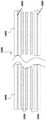
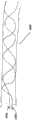
图19图示了根据本发明的实施例的柔性内窥镜仪器的管腔内的螺旋形图案的结构。在图19中,管腔1900包含沿其壁形成螺旋或螺旋形图案的结构1901和1902。在优选实施例中,结构由轴向刚硬和管状料形成。在一些实施例中,结构可以由皮下注射管(“hypo管”)、盘管或扭矩管形成。如由结构1901和1902所示,结构可以沿着管腔1900的壁具有不同的起点。还可以选择结构1901和1902的材料、组成和特点并且针对所期望的刚度和长度,进行配置。由结构1901和1902所形成的螺旋图案的俯仰还可以被配置用于管腔1900的所期望的刚度和灵活性。在一些实施例中,管腔1900可以是柔性内窥镜的主中央管腔,诸如图16的导引件1600。19 illustrates the structure of a helical pattern within a lumen of a flexible endoscopic instrument according to an embodiment of the present invention. In Figure 19,
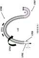
图20A图示了根据本发明的实施例的来自机器人腔内系统的内窥镜工具。内窥镜工具2000可以包括支撑底座(未示出)近端的柔性轴段2001和联接到远端尖端2003的柔性关节连接段2002。与导引件2005类似,内窥镜工具2000可以通过对轴内的筋放置拉伸载荷来进行关节连接。20A illustrates an endoscopic tool from a robotic intraluminal system according to an embodiment of the present invention.
图20B图示了图20A的内窥镜器械2000的备选视图。如图20B所示,远端尖端2003可以包括工作通道2004、四个发光二极管2005和数字相机2006。结合LED 2005,数字相机2006可以例如用来捕获实时视频以在解剖管腔内辅助导航。在一些实施例中,远端尖端2003可以包括容纳数字成像器件和照明器件的集成相机组件。Figure 20B illustrates an alternate view of the
工作通道2004可以用于术中仪器(诸如手术部位处的精密关节连接的柔性件)的通路。在其它实施例中,可以合并工作通道以提供附加能力,诸如冲洗、吸气、照明或激光能量。工作通道还可能有利于路由控制筋组件和上述附加能力所需的其它管腔。内窥镜工具的工作通道还可以被配置成递送多种其它治疗性物质。这种物质可以对于消融、放射或干细胞是低温的。这些物质可以使用本发明的内窥镜工具的插入、关节连接和能力精确地被递送到靶部位。在一些实施例中,工作通道的直径可以小至1.2毫米。The working
在一些实施例中,电磁(EM)追踪器可以合并到远端尖端2003以便帮助定位。如稍后将讨论的,在静态EM场发生器中可以用来确定EM追踪器的位置,并且因此实时确定远端尖端2003。In some embodiments, an electromagnetic (EM) tracker may be incorporated into the
来自相机2006的图像可能对于在解剖空间中导航是理想的。因此,当导航时,内部体液(诸如粘液)模糊相机2006可以引起问题。因此,内窥镜工具2000的远端2003还可以包括用于清洁相机2006的器件,诸如用于冲洗和抽吸相机透镜的器件。在一些实施例中,工作通道可以包含可以相机镜头周围充填有流体并且一旦透镜清晰就被抽吸的气球。Images from
内窥镜工具2000使得能够在腔内空间内递送并且操纵小型仪器。在优选的实施例中,可以小型化远端尖端以便执行腔内过程,从而维持外径不超过三毫米(即,在法国,9毫米)。
图21图示了根据本发明的实施例的内窥镜工具的远端。如图21A所示,内窥镜工具2100包括具有外壳2102的远端2101。壳2102可以由包括不锈钢和聚醚醚酮(PEEK)在内的若干种材料构造。远端2101可以装填有工作通道2103用于滑动地提供工具访问和控制。远端2101还提供了发光二极管2104的阵列用于使用相机2105照明。在一些实施例中,相机可以是较大传感器组件中的一部分,其包括一个或多个计算机处理器、印刷电路板和存储器。在一些实施例中,传感器组件还可以包括其它电子传感器,诸如陀螺仪和加速度计(用途稍后进行讨论)。21 illustrates the distal end of an endoscopic tool according to an embodiment of the present invention. As shown in FIG. 21A , an
8.内窥镜工具制造8. Endoscopic tool manufacturing
在背景技术中,可操控导管传统上由编织机(即,编织器)中具有拉管腔的工艺芯轴周围的编织线或纤维(即,编织线)和涂覆在编织线上的聚合物外套制造。可以使用可操控导管构造方法的各个方面构造内窥镜工具的护套和导引件的实施例。In the background art, steerable catheters are traditionally made of braided wire or fibers (ie, braided wire) around a process mandrel in a braiding machine (ie, braider) with a pulling lumen and a polymer coated on the braided wire Outerwear manufacturing. Embodiments of the sheath and guide of the endoscopic tool can be constructed using various aspects of the steerable catheter construction method.
图22图示了根据本发明的实施例的构造具有螺旋状管腔的内窥镜设备的流程图。开始,在步骤2201中,可以选择主工艺芯轴以创建可以用作工作通道的中心管腔的内窥镜中的腔。可以选择辅助芯轴来在内窥镜的壁中创建腔用作控制(牵拉)管腔。主工艺芯轴可以展示比辅助芯轴外径(OD)大的外径,以反映工作通道和牵拉管腔之间的相对尺寸差。辅助芯轴可以由可以涂有或没有涂有润滑涂层(诸如PTFE)的金属或热固性聚合物构造。22 illustrates a flow chart for constructing an endoscopic device having a helical lumen in accordance with an embodiment of the present invention. To begin, in step 2201, a main process mandrel can be selected to create a lumen in the endoscope that can be used as the central lumen of the working channel. A secondary mandrel can be selected to create a lumen in the wall of the endoscope for use as a control (stretching) lumen. The primary process mandrel may exhibit a larger outer diameter than the secondary mandrel outer diameter (OD) to reflect the relative size difference between the working channel and the puller lumen. The secondary mandrel may be constructed of metal or thermoset polymer that may or may not be coated with a lubricating coating such as PTFE.
在步骤2202中,主工艺芯轴可以被插入到编织器的进料管,其相对于固定编织锥支撑管和编织锥保持器转动。类似地,辅助芯轴还可以以与主工艺芯轴平行的方式被插入到进料管中。在传统的内窥镜构造中,较小辅助芯轴通过角齿轮的中心用于编织。In step 2202, the main process mandrel may be inserted into the feed tube of the braider, which is rotated relative to the fixed braided cone support tube and braided cone retainer. Similarly, the auxiliary mandrel can also be inserted into the feed tube in parallel with the main process mandrel. In conventional endoscopic configurations, a smaller auxiliary mandrel is used for braiding through the center of the angle gear.
在步骤2203中,使用具有胎面的牵拉器,主工艺芯轴可以前进通过进料管。当主工艺芯轴前进时,其最终通过鼻锥中的中心孔出现。类似地,辅助芯轴前进通过也以通过鼻锥中的外孔出现。这与传统内窥镜构造形成对比,其中,辅助芯轴通常通过分离的进料管前进以从角齿轮的中心出现。In step 2203, the main process mandrel may be advanced through the feed tube using the treaded retractor. As the main process mandrel advances, it eventually emerges through the central hole in the nose cone. Similarly, the advancement of the auxiliary mandrel also occurs through the outer hole in the nose cone. This is in contrast to traditional endoscope configurations, where the auxiliary mandrel is usually advanced through a separate feed tube to emerge from the center of the angle gear.
在步骤2204中,当主工艺芯轴和辅助芯轴通过鼻锥出现时,使用编织线把它们编织在一起。鼻锥提供了圆形平滑形状,在其上,来自周围的角齿轮的编织线可以在编织过程期间在主工艺芯轴周围轻易地滑动。当主工艺芯轴和辅助芯轴从鼻锥中出现时,鼻锥转动,从而确保外孔中的辅助芯轴在主工艺芯轴周围以螺旋形方式编织。当主工艺芯轴和辅助芯轴被编织在一起时,角齿轮平移并且转动来将编织线以预先确定的图案和密度放置在主工艺芯轴和辅助芯轴周围。In step 2204, the main process mandrel and the auxiliary mandrel are braided together using braided wire as they emerge through the nose cone. The nose cone provides a rounded smooth shape on which the braided wire from the surrounding angle gears can slide easily around the main process mandrel during the braiding process. As the main process mandrel and the auxiliary mandrel emerge from the nose cone, the nose cone rotates, ensuring that the auxiliary mandrel in the outer hole is woven in a helical fashion around the main process mandrel. When the main process mandrel and the auxiliary mandrel are braided together, the angle gear translates and rotates to place the braided wire around the main process mandrel and the auxiliary mandrel in a predetermined pattern and density.
这种编织方法与传统的内窥镜构造方法显著不同,其中,鼻锥通常保持在使用键控到编织锥保持器的紧定螺钉相对于编织锥保持器径向固定的位置中。因此,编织过程需要专用软件以便制造具有螺旋控制管腔的导管状内窥镜。This braiding method differs significantly from traditional endoscope construction methods in which the nose cone is typically held in a radially fixed position relative to the braided cone holder using set screws keyed to the braided cone holder. Therefore, the braiding process requires specialized software in order to manufacture a catheter-like endoscope with a helical control lumen.
图23图示了根据本发明的实施例的用于制造具有螺旋牵拉管腔的内窥镜的专用系统。在系统2300中,鼻锥2301可以使用将鼻锥2301相对于进料管2302保持在固定位置的紧定螺钉固定联接到转动进料管2302。因此,当进料管2302转动时,鼻锥2301转动。与此相反,传统系统通常使用紧定螺钉以将鼻锥2301固定联接到不转动的编织锥支撑保持器2305。Figure 23 illustrates a dedicated system for manufacturing an endoscope with a helical pull lumen in accordance with an embodiment of the present invention. In
鼻锥2301的中心孔2303可以与转动进料管2302对齐,以便通过两个结构顺利地牵拉主工艺芯轴2304。在一些实施例中,转动进料管2302的外径小于编织锥支撑管2306(还被称为芯轴引导管)的内径,并且内径大于鼻锥2301的中心孔2303的周向空间。转动进料管2302通常对于主工艺芯轴2304和辅助芯轴可以足够大以通过到鼻锥2301而不缠结。在一些实施例中,转动进料管2302可以足够长以穿过编织器的角齿轮的中心。在一些实施例中,转动进料管2302可以附接到可以保持通过进料管2302被传递到鼻锥2301周围的辅助孔的辅助芯轴的材料线轴的机构。The
在一些实施例中,进料管2302可以附接到控制进料管2302的转动速度从而控制鼻锥2301的转动的驱动机构。在一些实施例中,驱动机构可以是转动齿轮2307。当编织器正在在主工艺芯轴2304周围编织编织线2308时,驱动机构齿轮连接于编织器本身或独立地被控制以变化或保持转动进料管2302的转动速度并且因此鼻锥2301的转动速度恒定。转动速度和编织速度将管控辅助芯轴在主工艺芯轴2304上的俯仰。如之前所讨论的,这可能影响设备的柔性、刚度和“可推动性”。In some embodiments, the
图24图示了根据本发明的实施例的用于制造内窥镜设备中的螺旋管腔的专用鼻锥。在主工艺芯轴被牵拉通过鼻锥的同时转动鼻锥允许辅助芯轴2402,2403和2404通过分别包围中心孔2408的辅助孔2405,2406和2407应用于芯轴2401周围的螺旋图案,类似于角齿轮如何在主工艺芯轴2401周围编织编织线。Figure 24 illustrates a dedicated nose cone for use in manufacturing a helical lumen in an endoscopic device, according to an embodiment of the present invention. Rotating the nose cone while the main process mandrel is being pulled through the nose cone allows
在另一实施例中,变化牵拉管腔的圆周取向可以改变内窥镜的螺旋段的刚度。在制造中,这可以通过更改辅助螺旋形芯轴的俯仰来实现。当芯轴的俯仰(即,偏离纵向轴线的角度)增加时,所编织的复合材料的弯曲刚度减小。相反,当辅助芯轴的俯仰减少时,弯曲刚度增加。如图15B所示,在一些实施例中,辅助芯轴的俯仰可以在螺旋状部分(1510)内变化。在那些实施例中,所编织的复合材料的弯曲刚度可能甚至在螺旋状部分内变化。In another embodiment, varying the circumferential orientation of the puller lumen can vary the stiffness of the helical segment of the endoscope. In manufacturing, this can be achieved by changing the pitch of the auxiliary helical mandrel. As the pitch (ie, the angle from the longitudinal axis) of the mandrel increases, the bending stiffness of the woven composite decreases. Conversely, when the pitch of the auxiliary mandrel decreases, the bending stiffness increases. As shown in Figure 15B, in some embodiments, the pitch of the auxiliary mandrel may vary within the helical portion (1510). In those embodiments, the flexural stiffness of the woven composite material may even vary within the helical portion.
返回到图22,在步骤2205中,在完成编织过程后,聚合物涂层或外套可以装上护套、加热并且粘合到编织复合材料。聚合物涂层还可以应用于过挤出或薄膜浇铸过程。在步骤2206中,在粘合之后,芯轴可以从所编织的复合物中去除以创建中央管腔或用于相机和光工具的工作通道(主工艺芯轴)、以及用于操控控制的几个控制管腔(辅助芯轴)。已经去除了芯轴的所编织的复合材料可以完成(2207)。Returning to Figure 22, in step 2205, after the weaving process is complete, the polymer coating or jacket may be sheathed, heated, and bonded to the woven composite. Polymer coatings can also be applied in overextrusion or film casting processes. In step 2206, after bonding, the mandrel may be removed from the braided composite to create a central lumen or working channel (main process mandrel) for cameras and light tools, and several for steering control Control lumen (auxiliary mandrel). The braided composite material with the mandrel removed can be completed (2207).
在编织过程期间,可能停止编织机以使对所编织的复合材料进行更改。在一些实施例中,一次更改可以是增加平直线或加强杆。加强杆可能显著改变所编织的层压复合材料的屈曲、轴向和弯曲刚度。加强杆可以对于可能需要专门的抗屈曲构造或手工辅助来降低设备的屈曲,以使其可以插入到患者体内的较长的内窥镜特别有帮助。在一些实施例中,编织机可以被配置成选择性地编织可能从鼻锥中的孔被牵拉到主工艺芯轴上的加强杆,其中,加强杆被捕获并且被编织线保持在原位。所得内窥镜的远端区中没有加强杆保有了远端的设备灵活性,同时增加近端区的刚度。特性组合使得医师更容易地导航所得内窥镜、把设备插入并且推入患者的腔内空腔中。During the knitting process, the knitting machine may be stopped to allow changes to be made to the knitted composite material. In some embodiments, a modification may be the addition of a flat line or stiffener. Reinforcing rods can significantly alter the buckling, axial and bending stiffness of the woven laminate composite. Reinforcing rods may be particularly helpful for longer endoscopes that may require specialized buckling-resistant construction or manual assistance to reduce buckling of the device so that it can be inserted into a patient. In some embodiments, the braiding machine may be configured to selectively braid reinforcement rods that may be drawn from holes in the nose cone onto the main process mandrel, wherein the reinforcement rods are captured and held in place by the braided wire . The absence of reinforcing rods in the distal region of the resulting endoscope preserves distal device flexibility while increasing stiffness in the proximal region. The combination of features makes it easier for the physician to navigate the resulting endoscope, insert and advance the device into the patient's intraluminal cavity.
使用转动鼻锥中的孔把辅助芯轴施加到主工艺芯轴上提供了若干个制造优点。通过使用鼻锥中的孔,不从角齿轮推动芯轴。从还负责织造编织线的各个角齿轮的中心推动芯轴导致芯轴与编织线交织在一起,其沿纵向将所得编织矩阵锁定在原位。这种构造形式(被称为“零度构造”)限制了生产商调整编织矩阵用于理想灵活性或者环向强度的能力。在零度构造中,辅助芯轴必然以“上下方式”受限于编织,从而导致所有顺时针编织的编织线织造在辅助芯轴“上”,同时所有逆时针编织的编织线被制造在辅助芯轴“下”。当零度构造将辅助芯轴径向锁定在原位时,需要沿着主工艺芯轴变化辅助芯轴的俯仰可能是不希望的。Using the hole in the turning nose cone to apply the auxiliary mandrel to the main process mandrel provides several manufacturing advantages. By using the hole in the nose cone, the mandrel is not pushed from the angle gear. Pushing the mandrel from the center of each angle gear that is also responsible for weaving the braided wire causes the mandrel to interweave with the braided wire, which locks the resulting braided matrix in place longitudinally. This form of construction (referred to as a "zero degree construction") limits the ability of the manufacturer to adjust the braided matrix for desired flexibility or hoop strength. In the zero-degree configuration, the auxiliary mandrel is necessarily constrained to weave in an "up and down manner", resulting in all clockwise knitted braid threads being woven "on" the auxiliary mandrel, while all counter-clockwise braided threads are made on the auxiliary core axis "down". The need to vary the pitch of the secondary mandrel along the main process mandrel may be undesirable when the zero degree configuration locks the secondary mandrel radially in place.
附加地,角齿轮使用作为用于辅助芯轴的通道(pass through)限制了可以施加到主工艺芯轴的辅助芯轴的数目。例如,十六锭编织器(carrier braider)最多可以施加高达八个芯轴,二十四锭编织器只能具有高达十二个芯轴。与此相反,使用鼻锥中的孔允许任何数目的芯轴通过到达主工艺芯轴。Additionally, the use of the angle gear as a pass through for the auxiliary mandrel limits the number of auxiliary mandrels that can be applied to the main process mandrel. For example, a sixteen carrier braider can apply up to eight mandrels and a twenty-four carrier braider can only have up to twelve mandrels. In contrast, the use of holes in the nose cone allows any number of mandrels to pass through to the main process mandrel.
在一些实施例中,辅助芯轴可以施加到主工艺芯轴,而没有获益于第二外层的编织线。相反,可以在没有编织线的情况下施加辅助芯轴。在那些实施例中,粘合/融合的聚合物外套可以保持芯轴并且因此保持管腔在原位。可替代地,在一些实施例中,芯轴可以在所编织的复合物周围使用铸件保持在原位。因为在制造内窥镜工具中不存在外编织层,所以设备的横截面的直径和周长减少。可替代地,辅助芯轴可以通过在主工艺芯轴上套上聚合物外套来保持在原位。在一些实施例中,铸件可以是与用于内窥镜工具的外部材料相同的材料。In some embodiments, the auxiliary mandrel may be applied to the main process mandrel without benefiting from the braided wire of the second outer layer. Conversely, the auxiliary mandrel can be applied without the braided wire. In those embodiments, the bonded/fused polymer jacket can hold the mandrel and thus the lumen in place. Alternatively, in some embodiments, the mandrel may be held in place using a casting around the woven composite. Because the outer braid is not present in the manufacture of the endoscopic tool, the diameter and circumference of the cross-section of the device is reduced. Alternatively, the secondary mandrel may be held in place by placing a polymer jacket over the main process mandrel. In some embodiments, the casting may be the same material as the outer material used for the endoscopic tool.
在一些实施例中,辅助芯轴可以很像编织物线一样被编织到主工艺芯轴上。例如,在一些实施例中,可以使用偶数个角齿轮编织辅助芯轴,同时通过使用奇数个角齿轮编织的编织线来保持在原位。这样,辅助芯轴并且因此管腔可以被织造到中心管腔的壁中。作为附加益处,使用这种期间制造的实施例往往还具有较低的圆周区域。In some embodiments, the secondary mandrel may be woven onto the primary process mandrel much like a braid wire. For example, in some embodiments, the auxiliary mandrel may be braided using an even number of angle gears while being held in place by a braided wire braided using an odd number of angle gears. In this way, the auxiliary mandrel and thus the lumen can be woven into the wall of the central lumen. As an added benefit, embodiments fabricated using such periods also tend to have lower circumferential areas.
可替代地,在一些实施例中,可以使用挤压模具制造螺旋状管腔结构。这些模具可以生成螺旋状管腔结构以由PTFE、聚醚酰胺(pebax)、聚氨酯和尼龙创建外套。在一些实施例中,可以使用模具在编织的芯轴周围形成挤压结构。Alternatively, in some embodiments, an extrusion die may be used to manufacture the helical lumen structure. These molds can create helical lumen structures to create jackets from PTFE, polyetheramide (pebax), polyurethane, and nylon. In some embodiments, a die may be used to form an extruded structure around a braided mandrel.
在一些实施例中,螺旋管腔构造可以当通过编织器拖拉主工艺芯轴时通过转动它来执行。通过转动主工艺芯轴而非鼻锥,可以在编织过程期间通过固定鼻锥或通过角齿轮拖拉辅助芯轴。在该实施例中,鼻锥可以固定联接到鼻锥保持器,并且当通过鼻锥拖拉主工艺芯轴时,转动鼻锥拖拉主工艺芯轴。In some embodiments, the helical lumen configuration may be performed by rotating the main process mandrel as it is pulled through the braider. By turning the main process mandrel instead of the nose cone, the auxiliary mandrel can be pulled during the knitting process by means of the fixed nose cone or through the angle gear. In this embodiment, the nose cone may be fixedly coupled to the nose cone holder, and when the main process mandrel is pulled through the nose cone, the main process mandrel is pulled by rotating the nose cone.
图15的护套1500和图16的导引件1600的构造基本上相同。因此,本领域技术人员应当理解,相同的原理也适用于这两种工具。The construction of the
9.腔内导航9. Intraluminal Navigation
在本发明的实施例中,通过解剖管腔导航内窥镜工具可能牵涉到使用基于由低剂量电脑断层扫描(CT)扫描创建的二维图像的集合使用计算机生成三维地图。可以在手术前过程期间收集每个表示患者的内部解剖结构的剖视图的二维CT扫描。可以对这些扫描进行分析以确定患者体内的腔体和解剖空间,诸如肺的分支或尿道的路径。In embodiments of the invention, navigating an endoscopic tool through a dissecting lumen may involve generating a three-dimensional map using a computer based on a collection of two-dimensional images created from low-dose computed tomography (CT) scans. Two-dimensional CT scans, each representing a cross-sectional view of the patient's internal anatomy, can be collected during the preoperative procedure. These scans can be analyzed to determine cavities and anatomical spaces within the patient, such as branches of the lungs or the path of the urethra.
已经进行了分析以确定患者体内的相关解剖空间,该空间可以被表达为在三维空间中具有中心线坐标(即,表示管腔中心的坐标)的管腔。那些腔体的体积可以表示为各中心线坐标处的直径距离的特定测量值。通过追踪中心线与对应的直径距离测量值,可以生成三维管腔的计算机生成模型。网格坐标数据可以因此用来表达三维空间和表示患者的解剖结构的腔体。Analysis has been performed to determine the relevant anatomical space within the patient, which can be expressed as a lumen having centerline coordinates (ie, coordinates representing the center of the lumen) in three-dimensional space. The volumes of those cavities can be expressed as specific measurements of diametric distances at each centerline coordinate. By tracing the centerline to the corresponding diametrical distance measurements, a computer-generated model of the lumen in three dimensions can be generated. The grid coordinate data can thus be used to represent the three-dimensional space and cavities representing the patient's anatomy.
图25图示了中心线坐标、直径测量值和解剖空间之间的关系。在图25A中,解剖管腔2500可以大致由中心线坐标2501,2502,2503,2504,2505和2506沿纵向进行追踪,其中,每个中心线坐标大致接近管腔的中心。通过连接这些坐标,如“中心线”2507所示,可以可视化管腔。管腔的体积可以进一步通过测量各中心线坐标处管腔的直径进行可视化。因此,2508,2509,2510,2511,2512和2513表示坐标2501,2502,2503,2504,2505和2506处管腔2500的测量值。Figure 25 illustrates the relationship between centerline coordinates, diameter measurements, and anatomical space. In Figure 25A, an anatomical lumen 2500 may be traced longitudinally approximately by
在图25B中,可以通过基于中心线2507首先定位三维空间的中心线坐标2501,2502,2503,2504,2505和2506在三维空间中可视化管腔2500。在每个中心线坐标处,管腔直径可以被可视化为具有直径2508,2509,2510,2511,2512和2513的二维圆形空间。通过以三维连接那些二维圆形空间,管腔2500可以被近似为三维模型2514。更准确近似值可以通过针对给定管腔或子段增加中心线坐标的分辨率和测量值(即,增加中心线坐标的密度和测量值)来确定。中心线坐标还可以包括用来指示医师包括病变在内的感兴趣点的标记。In Figure 25B, lumen 2500 can be visualized in three-dimensional space by first locating centerline coordinates 2501, 2502, 2503, 2504, 2505, and 2506 in three-dimensional space based on
已经表达并且随后生成了解剖空间的三维模型,手术前软件包还可以用来基于所生成的模块分析并且导出最佳导航路径。例如,该软件包可以导出到单个病变(由中心线坐标标记)或几个病变的最短路径。该路径可以根据操作者的偏好在术中以二维或三维被呈现给操作者。Having expressed and subsequently generated a three-dimensional model of the anatomical space, the pre-operative software package can also be used to analyze and derive optimal navigation paths based on the generated modules. For example, the package can export the shortest path to a single lesion (marked by centerline coordinates) or several lesions. The path may be presented to the operator intraoperatively in two or three dimensions, depending on the operator's preference.
图26图示了根据本发明的实施例的表示解剖空间的计算机生成三维模型。如前面所讨论的,可以使用通过审查术前执行的CT扫描获得的中心线2601来生成模型2600。在一些实施例中,计算机软件能够映射腔内系统的最佳路径2602以进入模型2600内的手术部位2603,并且因此进入相应的解剖空间。在一些实施例中,手术部位2603可以与单独的中心线坐标2604相关,其允许计算机算法拓扑搜索腔内系统的最佳路径2602的模型2600的中心线。26 illustrates a computer-generated three-dimensional model representing an anatomical space in accordance with an embodiment of the present invention. As previously discussed, the
追踪患者的解剖结构内的内窥镜工具的远端并且将该位置映射到计算机模型内的放置,增强腔内系统的导航能力。为了追踪内窥镜工具的远端工作端,即,工作端的“定位”,可以单独或组合采用若干种途径。Tracking the distal end of the endoscopic tool within the patient's anatomy and mapping this location to placement within the computer model enhances the navigation capabilities of the intraluminal system. In order to track the distal working end of the endoscopic tool, ie, the "positioning" of the working end, several approaches can be employed, alone or in combination.
在基于传感器的定位途径中,传感器(诸如电磁(EM)追踪器)可以联接到内窥镜工具的远端工作端以提供内窥镜工具的进展的实时指示。在基于EM的追踪中,嵌入内窥镜工具的EM追踪器测量由一个或多个静态EM发射机产生的电磁场的变化。发射机(或场发生器)可以被放置在靠近患者以产生低强度磁场。这在EM追踪器中的传感器线圈中感应电流,该传感器线圈与传感器和发生器之间的距离和角度相关。电信号然后可以通过接口单元(片上或PCB)被数字化,并且经由电缆/布线发送回系统推车,然后发送到命令模块。然后,数据可以被处理以解释当前数据,并且计算传感器相对于发射机的精确位置和取向。多个传感器可以用于内窥镜设备中(比如在导引件和护套中)的不同位置,以便计算这些部件的单独位置。因此,基于来自人工生成EM场的读数,当EM追踪器可以移动通过患者的解剖结构时,它可以检测到场强度的改变。In a sensor-based positioning approach, a sensor, such as an electromagnetic (EM) tracker, can be coupled to the distal working end of the endoscopic tool to provide real-time indication of the progress of the endoscopic tool. In EM-based tracking, an EM tracker embedded in an endoscopic tool measures changes in the electromagnetic field produced by one or more static EM transmitters. A transmitter (or field generator) can be placed close to the patient to generate a low-strength magnetic field. This induces a current in the sensor coil in the EM tracker, which is related to the distance and angle between the sensor and the generator. The electrical signals can then be digitized by the interface unit (on-chip or PCB) and sent back to the system cart via cables/wiring, and then to the command module. The data can then be processed to interpret the current data and calculate the precise position and orientation of the sensor relative to the transmitter. Multiple sensors can be used at different locations in the endoscopic device (such as in the guide and sheath) in order to calculate the individual positions of these components. Thus, based on readings from artificially generated EM fields, the EM tracker can detect changes in field strength as it can move through the patient's anatomy.
图27图示了根据本发明的实施例的与电磁场发生器组合利用电磁追踪器的机器人腔内系统。当机器人系统2700驱动机器人驱动的内窥镜工具2701进入到患者2702中时,内窥镜工具2701的远端处的电磁(EM)追踪器2703可以检测到由EM场发生器生成的EM场2704。EM追踪器2703的EM读数可以沿着内窥镜工具2701的轴传输到系统推车2705和命令模块2706(其包含相关的软件模块、中央处理单元、数据总线和存储器)用于解释和分析。使用来自EM追踪器2703的读数,显示模块2707可以显示预先生成的三维模型内的EM追踪器的相对位置用于由操作者2708审查。实施例还提供了其它类型的传感器(诸如纤维光纤形状的传感器)的使用。尽管可以使用多种传感器用于追踪,可以固有地基于(i)内窥镜工具内的传感器的尺寸和(ii)制造并且把传感器集成到内窥镜工具中的成本限制传感器的选择。27 illustrates a robotic intracavity system utilizing an electromagnetic tracker in combination with an electromagnetic field generator in accordance with an embodiment of the present invention. When the
在通过患者的解剖结构追踪传感器之前,追踪系统可能需要被称为“配准”的过程,其中,系统发现对齐不同坐标系之间的单个对象的几何变换。比如,患者身上的特定解剖部位在CT模型坐标中和在EM传感器坐标中具有两个不同表示。为了能够在这些坐标系之间建立一致性和通用语言,该系统需要找到联系这两个表示(即,配准)的变换。换句话说,EM追踪器相对于EM场发生器的位置的位置可以被映射到三维坐标系以隔离对应的三维模型中的位置。Before tracking the sensor through the patient's anatomy, the tracking system may require a process known as "registration," in which the system finds geometric transformations that align individual objects between different coordinate systems. For example, a specific anatomy on a patient has two different representations in CT model coordinates and in EM sensor coordinates. In order to be able to establish consistency and a common language between these coordinate systems, the system needs to find a transformation linking the two representations (ie, registration). In other words, the position of the EM tracker relative to the position of the EM field generator can be mapped to a three-dimensional coordinate system to isolate the corresponding position in the three-dimensional model.
在一些实施例中,可以在几个步骤中执行配准。图28图示了根据本发明的实施例的用于配准过程的流程图。开始,在步骤2801中,操作者必须首先将内窥镜工具的工作端定位在已知的起始位置。这可能牵涉到使用来自内窥镜相机的视频图像数据以确认起始位置。初始定位可以通过位于内窥镜的工作端处的相机标识解剖学特征来完成。例如,在支气管镜检查中,配准可以通过定位气管的底部来执行,该气管的底部通过定位用于左肺、右肺的两个主支气管来区分。该位置可以使用由内窥镜的远端中的相机接收的视频图像来确定。在一些实施例中,视频数据可以与患者的解剖结构的预先生成的计算机模型的不同的横截面视图相比较。通过排序横截面视图,该系统可以标识与具有最小数量的差异或“误差”的横截面相关联的位置以找到“匹配”。In some embodiments, registration may be performed in several steps. Figure 28 illustrates a flow diagram for a registration process according to an embodiment of the present invention. To begin, in
在步骤2802中,操作者可以“驱动”或将内窥镜工具“延伸”到已经被映射的独特解剖空间中。例如,在支气管镜检查中,操作者可以从气管的底部沿着独特支气管路径驱动内窥镜。因为气管的底部分成两个支气管,所以操作者可以将内窥镜工具驱动到一个管中,并且使用EM追踪器追踪内窥镜工具的工作端。In
在步骤2803中,操作者监控内窥镜工具的相对行进。内窥镜工具的监控可以利用EM追踪器或荧光镜检查以确定内窥镜工具的相对运动。内窥镜工具的工作端的相对位移的评价可以与由手术前CT扫描数据生成的计算机模型相比较。在一些实施例中,相对运动可以与计算机模型中的中心线匹配,其中,变换矩阵导致最小误差是正确配准。在一些实施例中,系统和操作者可以追踪来自加速度计和/或陀螺仪(下文所讨论的)的插入数据(下文所讨论的)和取向数据。In
在步骤2804中,操作者可以决定驱动到更多个解剖空间(2802)中并且在比较和分析位置数据之前收集更多位置信息(2803)。例如,在支气管镜检查中,操作者把内窥镜从一个支气管缩回到支气管套管并且将内窥镜驱动到另一支气管套管以便收集更多的位置数据。一旦操作者被满足时,操作者就可以停止驱动(2802)并且监控位置数据(2803),并且继续处理数据。In
在步骤2805中,系统可以分析所收集的位置数据并且将该数据与预先生成的计算机模型进行比较以将患者的解剖结构内的内窥镜的位移配准到模型。因此,通过比较患者的解剖结构中的运动和患者的解剖结构的三维模型,该系统能够相对于两个空间(三维计算机模型vs患者的解剖空间)配准追踪器。在分析之后,配准过程可能完成(2806)。In
在一些情况中,可能有必要执行“滚动配准”以便确认内窥镜工具的取向。这可能在驱动到未配准的解剖空间之前,在步骤2801中尤为重要。在支气管镜检查中,正确的垂直取向确保操作者可以在右和左支气管之间进行区分。例如,在气管的底部内,不管相机是否成零度或180度定向,左支气管和右支气管的图像都可能显得非常相似。因为内窥镜工具的运动在患者体内曲折导航期间通常导致轻微转动,所以滚动配准还可能是重要的。In some cases, it may be necessary to perform a "roll registration" in order to confirm the orientation of the endoscopic tool. This may be especially important in
当工作通道可以被传感器占据时,滚动配准在手术部位可能是重要的。例如,在仅具有单个工作通道的实施例中,在到达手术部位时,医师可能需要从内窥镜工具去除EM追踪器,以便使用另一工具,诸如抓紧器或镊子。然而,在去除之后,该系统可以在没有EM追踪器的情况下失去其定位能力。因此,当准备离开手术区时,EM追踪器的插入可以要求滚动配准被再次执行以确保正确的取向。Roll registration can be important at the surgical site when the working channel can be occupied by the sensor. For example, in embodiments with only a single working channel, upon reaching the surgical site, the physician may need to remove the EM tracker from the endoscopic tool in order to use another tool, such as a grasper or forceps. After removal, however, the system can lose its localization capabilities without the EM tracker. Thus, when preparing to leave the surgical field, insertion of the EM tracker may require that roll registration be performed again to ensure proper orientation.
在一些实施例中,内窥镜工具的转动可以使用安装在设备的远端工作端内的加速度计进行追踪。使用加速度计来检测内窥镜上的重力提供关于内窥镜工具相对于地面的位置信息。地面相对于内窥镜的位置可以用来解决某些歧义。在支气管镜检查中,例如,了解内窥镜的远端相机的取向(0度或180度)可能有助于在开始时确定适当的支气管分支。在导航期间,用来追踪重力方向并且因此追踪取向的来自加速度计的数据还可以用来自动校正在控制台上显示的相机图像,从而确保了所显示的图像总是垂直取向。In some embodiments, the rotation of the endoscopic tool can be tracked using an accelerometer mounted within the distal working end of the device. Using an accelerometer to detect gravity on the endoscope provides information about the position of the endoscope tool relative to the ground. The position of the ground relative to the endoscope can be used to resolve some ambiguities. In bronchoscopy, for example, knowing the orientation of the distal camera of the endoscope (0 degrees or 180 degrees) may help determine the appropriate bronchial branch at the beginning. During navigation, the data from the accelerometer used to track the direction of gravity and therefore orientation can also be used to automatically correct the camera image displayed on the console, ensuring that the displayed image is always oriented vertically.
在优选实施例中,具有加速度计的基于3轴MEMS的传感器芯片可以在内窥镜设备的尖端附近联接在与数码相机相同的印刷电路板上。加速度计沿着三个不同轴线测量线性加速度来计算导管尖端的速度和方向。该加速度计还测量重力的方向,因此提供了关于内窥镜设备取向的绝对信息。加速度计读数通过像I2C的通信协议使用数字或模拟信号而被重新传输。该信号可以通过布线被传输到导管的近端,并且从那里传输到系统推车和命令模块进行处理。In a preferred embodiment, a 3-axis MEMS based sensor chip with an accelerometer can be coupled on the same printed circuit board as the digital camera near the tip of the endoscopic device. The accelerometer measures linear acceleration along three different axes to calculate the velocity and orientation of the catheter tip. The accelerometer also measures the direction of gravity, thus providing absolute information about the orientation of the endoscopic device. The accelerometer readings are retransmitted using digital or analog signals through a communication protocol like I2C. This signal can be routed to the proximal end of the catheter and from there to the system cart and command module for processing.
在三轴传感器中,加速度计能够确定地面相对于内窥镜的位置。如果内窥镜没有滚动或弯曲高达九十度,则两轴加速度计还可以有用。可替代地,如果加速度计的轴线保持垂直于重力方向(即,垂直于地面),则一轴传感器可以有用。可替代地,陀螺仪可以用来测量转动速度,然后可以用来计算内窥镜设备的关节连接。In a triaxial sensor, the accelerometer is able to determine the position of the ground relative to the endoscope. A two-axis accelerometer can also be useful if the endoscope is not rolled or bent up to ninety degrees. Alternatively, a one-axis sensor can be useful if the axis of the accelerometer remains perpendicular to the direction of gravity (ie, perpendicular to the ground). Alternatively, a gyroscope can be used to measure rotational speed, which can then be used to calculate the articulation of the endoscopic device.
一些实施例与加速度计组合使用EM追踪器,以补充来自加速度计的任何取向读数。在一些实施例中,使用荧光镜检查来追踪内窥镜工具还可以补充配准过程。如本领域中所公知的,荧光镜检查是使用X射线以通过使用荧光镜来获得患者的内部结构的实时移动图像的成像技术。通过荧光镜检查生成的二维扫描可以在某些情况下帮助定位,例如,标识相关支气管。Some embodiments use an EM tracker in combination with an accelerometer to supplement any orientation readings from the accelerometer. In some embodiments, the use of fluoroscopy to track the endoscopic tool may also complement the registration process. As known in the art, fluoroscopy is an imaging technique that uses X-rays to obtain real-time moving images of a patient's internal structures through the use of fluoroscopy. Two-dimensional scans generated by fluoroscopy can aid in localization in some cases, for example, to identify associated bronchi.
可以使用内窥镜上的多个不透辐射的标记来执行使用荧光镜检查的追踪。内窥镜的许多特点自然地对x射线是不透射的,包括相机头、控制环和拉线;因此,标记位置与内窥镜的金属部件一起可以用来获得三维变换矩阵。一旦配准已经发生,检测分支位置的视觉图像就可以与三维模型精确地相关。另外,可以在地图中测量并且增强3D中的全分支长度和分支位置。Tracking using fluoroscopy can be performed using multiple radiopaque markers on the endoscope. Many features of endoscopes are naturally radiopaque to x-rays, including the camera head, control ring, and pull wires; therefore, the marker locations, along with the metal parts of the endoscope, can be used to obtain a three-dimensional transformation matrix. Once the registration has occurred, the visual image of the detected branch location can be accurately correlated with the three-dimensional model. Additionally, full branch lengths and branch locations in 3D can be measured and enhanced in the map.
与基于传感器的途径相反,基于视觉的追踪牵涉到使用由在远端安装的相机生成的图像来确定内窥镜工具的位置。例如,在支气管镜检查中,特征追踪算法可以用来标识与支气管路径相对应的圆形几何形状,并且从图像到图像追踪这些几何形状的改变。通过当这些特征从图像到图像移动时追踪它们的方向,系统能够确定选择哪个分支、以及相机的相对转动和平移运动。支气管路径的拓扑地图的使用可以进一步增强基于视觉的算法。In contrast to sensor-based approaches, vision-based tracking involves the use of images generated by cameras mounted at the distal end to determine the position of the endoscopic tool. For example, in bronchoscopy, feature tracking algorithms can be used to identify circular geometries corresponding to bronchial paths and track changes in these geometries from image to image. By tracking the orientation of these features as they move from image to image, the system is able to determine which branch to select, as well as the relative rotational and translational motion of the cameras. The use of topological maps of bronchial pathways can further enhance vision-based algorithms.
除了基于特征的追踪之外,图像处理技术(诸如光流)还可以用来在支气管镜检查中标识气道拓扑的分支。光流是视频序列中的图像像素从一个图像到下一个图像的位移。相对于支气管镜检查,光流可以用来基于在内窥镜的尖端处接收的相机图像的改变来估计内窥镜的尖端的运动。具体地,在一系列视频帧中,可以分析每帧以检测像素从一个帧到下一个帧的平移。例如,如果给定帧中的像素看起来平移到下一帧中的左侧,则算法将推断相机并且依次内窥镜的尖端向右移动。通过比较经过许多迭代的许多个帧,可以确定内窥镜的运动(并且因此,位置)。In addition to feature-based tracking, image processing techniques such as optical flow can also be used to identify branches of airway topology in bronchoscopy. Optical flow is the displacement of image pixels in a video sequence from one image to the next. With respect to bronchoscopy, optical flow can be used to estimate motion of the tip of an endoscope based on changes in camera images received at the tip of the endoscope. Specifically, in a series of video frames, each frame can be analyzed to detect translation of pixels from one frame to the next. For example, if a pixel in a given frame appears to be shifted to the left in the next frame, the algorithm will infer the camera and in turn move the tip of the endoscope to the right. By comparing many frames over many iterations, the motion (and thus, position) of the endoscope can be determined.
在立体图像捕获(相对于单眼图像捕获)可用的情况下,光流技术还可以用来补充解剖区的预先存在的三维模型。使用立体图像捕获,可以确定二维捕获的图像中的像素的深度以建立相机视图中的对象的三维地图。外推以在解剖管腔内行进,该技术使得系统能够开发出内窥镜周围的局部环境的三维地图,同时在患者的解剖结构内部进行导航。这些地图可以用来延伸其中模型要么丢失数据要么质量低的预先确定的三维计算机模型。除了立体相机装置之外,可能需要使用深度传感器或特定照明配置和图像捕获技术(诸如RGB-D传感器或结构照明)。Where stereoscopic image capture (as opposed to monocular image capture) is available, optical flow techniques can also be used to supplement pre-existing three-dimensional models of anatomical regions. Using stereoscopic image capture, the depth of pixels in a two-dimensional captured image can be determined to build a three-dimensional map of objects in the camera's view. Extrapolated to travel within the anatomical lumen, this technique enables the system to develop a three-dimensional map of the local environment surrounding the endoscope while navigating inside the patient's anatomy. These maps can be used to extend predetermined three-dimensional computer models in which the model is either missing data or of low quality. In addition to stereo camera arrangements, the use of depth sensors or specific lighting configurations and image capture techniques (such as RGB-D sensors or structured lighting) may be required.
不管追踪方法是基于传感器的还是基于视觉的,追踪还是可以通过使用来自内窥镜工具本身的数据进行改进。例如,在图2的内窥镜工具200中,护套201和导引件205的相对插入长度可以从气管内已知的起始位置(在支气管镜检查的情况下)来测量。使用相对的插入长度和患者的支气管树的三维模型的中心线,该系统可以在确定内窥镜工具是否位于分支中和沿着该分支行进的距离之后,给定工作端的位置的粗略估计。还可以使用来自内窥镜工具的其它控制信息,诸如内窥镜设备的关节连接、滚动、或俯仰和偏航。Regardless of whether the tracking method is sensor-based or vision-based, tracking can still be improved by using data from the endoscopic tool itself. For example, in the
基于不同的成像模态的实时成像可能进一步加强导航,特别是在手术部位。即使追踪可以协助到手术部位的粗略导航,当更精确的处理是必要的时(诸如当试图活检病变时),附加模态可能是有用的。成像工具(诸如荧光成像、近红外成像、氧传感器、分子生物标记图像和对比染料成像)可以帮助在计算机模型中查明病变的准确坐标,并且因此辅助在手术部位操作活检针。在不存在精确位置的情况下,内窥镜工具可以用来以公知的深度活检手术部位的整个区域,因此确保对来自病变的组织进行采样。Real-time imaging based on different imaging modalities may further enhance navigation, especially at the surgical site. Even though tracking can assist with coarse navigation to the surgical site, additional modalities may be useful when more precise processing is necessary, such as when attempting to biopsy a lesion. Imaging tools such as fluorescence imaging, near-infrared imaging, oxygen sensors, molecular biomarker images, and contrast dye imaging can help pinpoint the exact coordinates of lesions in computer models, and thus assist in maneuvering biopsy needles at the surgical site. In the absence of precise locations, endoscopic tools can be used to biopsy the entire area of the surgical site at known depths, thus ensuring that tissue from the disease is sampled.
在一些情况中,分段CT扫描并且因此所得计算机模型没有示出肺部外周处的分支(在支气管镜检查的情景中)。这可以在扫描期间是由于气道的充气不足,或者因为分支的尺寸低于CT扫描(通常数量级为1毫米)的分辨率。在实践中,机器人系统可以通过指出未映射分支的地点和位置和取向在过程期间增强计算机模型。在一些实施例中,拓扑结构可以允许医师标记他们的位置并且返回到同一位置以便检查外周分支。在一些实施例中,内窥镜相机可以基于所捕获的图像测量分支的直径和形状,从而允许基于位置和方向映射那些分支。In some cases, the segmented CT scan, and thus the resulting computer model, did not show branches at the periphery of the lung (in the context of bronchoscopy). This can be due to underinflation of the airway during the scan, or because the size of the branches is lower than the resolution of CT scans (usually on the order of 1 mm). In practice, robotic systems can enhance computer models during the process by pointing out the locations and positions and orientations of unmapped branches. In some embodiments, the topology may allow physicians to mark their location and return to the same location to examine peripheral branches. In some embodiments, the endoscopic camera can measure the diameter and shape of branches based on the captured images, allowing those branches to be mapped based on position and orientation.
10.腔内过程10. Intraluminal Procedure
图29A图示了根据本发明的实施例的解剖管腔内的内窥镜工具的远端。在图29A中,示出了通过解剖管腔2902朝向手术部位2903导航的包括轴2901的内窥镜工具2900。在导航期间,轴2901可能未被关节连接。29A illustrates a distal end of an endoscopic tool within a dissection lumen according to an embodiment of the present invention. In Figure 29A, an
图29B图示了在解剖管腔内的手术部位处使用的图29A的内窥镜工具。已经到达手术部位2903的与轴2901纵向对齐的远端导引件段2904可以在由箭头2905标记的方向上从轴2901延伸。远端导引件段2904还可以关节连接以便朝向手术部位2903引导工具。Figure 29B illustrates the endoscopic tool of Figure 29A in use at a surgical site within a dissection lumen. The
图29C图示了在解剖管腔内的手术部分处使用的图29B的内窥镜工具。在手术部位包含活检病灶的情况下,远端导引件段2904可以在由箭头2906标记的方向上关节连接以传送抽吸针2907以瞄准手术部位2903处的病变。在一些实施例中,远端导引件段2904可以关节连接以引导活检镊子去除解剖组织样本用于术中评估的目的。出于激活该端部执行器的目的,内窥镜工具2900可以包括可操作地联接到活检镊子的筋。Figure 29C illustrates the endoscopic tool of Figure 29B in use at a surgical portion within a dissection lumen. Where the surgical site contains a biopsy lesion, the
图30A图示了根据本发明的实施例的联接到解剖管腔内的远端弯曲段的内窥镜工具。在图30A中,示出了通过解剖管腔3004朝向手术部位导航的包括轴3001、弯曲段3002和镊子3003的内窥镜工具3000。在导航期间,如图30A所示,轴3001和远端弯曲段3002可以未被关节连接。在一些实施例中,弯曲段3002可以在轴3001内缩回。在于2014年3月7日提交的美国专利申请号14/201,610和于2014年9月5日提交的美国专利申请号14/479,095中公开了弯曲段3002的构造、组成、能力和使用,其全部内容通过引用并入本文。30A illustrates an endoscopic tool coupled to a distal curved segment within a dissecting lumen, according to an embodiment of the present invention. In Figure 30A, an
在一些实施例中,弯曲段3002可以与轴3001纵向对齐。在一些实施例中,弯曲段3002可以通过偏离轴3001的轴线(中性轴线)的工作通道进行部署,从而允许在没有模糊位于轴3001远端的相机的情况下操作弯曲段3002。这种布置允许操作者使用相机来关节连接弯曲段3002,同时轴3001保持静止。In some embodiments,
类似于其它实施例,不同的工具(诸如镊子3003)可以通过弯曲段3002中的工作通道进行部署以用于弯曲段3002的远端。在其它场景中,外科手术工具(诸如抓紧器、解剖刀、针和探针可以位于弯曲段3002的远端。在内窥镜工具3000中,如在其它实施例中一样,可以在术中代替弯曲段的远端处的工具以便在单个过程中执行多次治疗。Similar to other embodiments, different tools, such as
图30B图示了根据本发明的实施例的在解剖管腔内的手术部位处使用的具有镊子工具的图30A的内窥镜工具。可以通过任何数目上文所讨论的各种导航技术指引通过解剖管腔3004导航内窥镜工具3000。一旦内窥镜工具3000已经达到手术部位3006处的其所期望的位置,弯曲段3002就可以在箭头3005的方向上关节连接,以便朝向手术部位3006定位镊子3003。使用镊子3003,内窥镜工具3000可以在手术部位3006进行组织活检。30B illustrates the endoscopic tool of FIG. 30A with a forceps tool for use at a surgical site within a dissection lumen in accordance with an embodiment of the present invention. Navigation of the
图30C图示了根据本发明的实施例的在解剖管腔内的手术部位处使用的具有激光设备的图30A的内窥镜工具。可以关节连接已经到达手术部位3006的内窥镜工具3000的弯曲段3002并且可以通过轴3001的工作通道和弯曲段3002部署激光工具3007。一旦被部署,激光工具3007可以被引导到手术部位3006以发射激光辐射3008用于组织消融、钻孔、切割、穿孔、清创、切割或进入非浅表组织的目的。30C illustrates the endoscopic tool of FIG. 30A with a laser device for use at a surgical site within an anatomical lumen in accordance with an embodiment of the present invention. The
11.命令控制台11. Command Console
如参照图1的系统100所讨论的,命令控制台的实施例允许操作者(即,医师)从人体工程学位置远程控制机器人腔内系统。在优选实施例中,命令控制台利用用户接口,其(ⅰ)使得操作者能够控制机器人内窥镜工具,并且(ii)从人体工程学位置显示导航环境。As discussed with reference to the
图31图示了根据本发明的实施例的用于机器人腔内系统的命令控制台。如图31所示,命令控制台3100可以包括底座3101、显示模块(例如,监控器3102)和控制模块(诸如键盘3103和操纵杆3104)。在一些实施例中,命令模块功能性可以被集成到具有机械手臂的系统推车中,诸如来自图1的系统100的系统推车101。31 illustrates a command console for a robotic intraluminal system in accordance with an embodiment of the present invention. As shown in FIG. 31, the
底座3101可以包括中央处理单元、存储器单元、数据总线和负责解释和处理来自内窥镜工具的信号(诸如相机图像和追踪传感器数据)的相关的数据通信端口。在其它实施例中,解释和处理信号的负担可能分布于相关的系统推车和命令控制台3100之间。底座3101还可以负责通过控制模块(诸如3103和3104)解释和处理来自操作者3105的命令和指令。The
控制模块负责捕获操作者3105的命令。除了图31中的键盘3103和操纵杆3104之外,控制模块可以包括本领域中已知的其它控制机构,包括但不限于计算机鼠标、触控板、轨迹球、控制垫和视频游戏控制器。在一些实施例中,还可以捕获手姿势和手指姿势以将控制信号递送到系统。The control module is responsible for capturing
在一些实施例中,可能存在多种控制器件。例如,对内窥镜工具的控制可以以“速度模式”或“位置控制模式”来执行。“速度模式”由基于直接手动控制(诸如通过操纵杆3104)直接控制内窥镜工具的远端的俯仰和偏航行为组成。例如,操纵杆3104上的右和左运动可以被映射到内窥镜工具的远端的偏航和俯仰运动。操纵杆的触觉反馈还可以用来以“速度模式”增强控制。例如,振动可以被发送回到操纵杆3104以传达内窥镜工具不能在一定方向上进一步关节连接或滚动。可替代地,弹出消息和/或音频反馈(例如,蜂鸣声)还可以用来传达内窥镜工具已经到达最大关节连接或滚动。In some embodiments, there may be multiple control devices. For example, control of the endoscopic tool may be performed in a "speed mode" or a "position control mode." "Speed Mode" consists of direct control of the pitch and yaw behavior of the distal end of the endoscopic tool based on direct manual control, such as through
“位置控制模式”由标识患者在三维地图中的位置并且依靠机器人系统基于预先确定的计算机模型以通过机器人操控内窥镜工具组成。由于其依赖患者的三维映射,所以位置控制模式需要患者的解剖结构的准确映射。The "position control mode" consists of identifying the position of the patient in the three-dimensional map and relying on the robotic system to manipulate the endoscopic tool by the robot based on a predetermined computer model. Since it relies on a three-dimensional mapping of the patient, the position control mode requires accurate mapping of the patient's anatomy.
在不使用命令模块3101的情况下,系统还可以直接由人工操作者操纵。例如,在系统设置期间,医师和助手可以移动机械手臂和内窥镜工具以在患者和手术室周围布置设备。在直接操纵期间,系统可以依赖于来自人类操作者的力反馈和惯性控制以确定适当的设备取向。Without using the
显示模块3102可以包括监控器、虚拟现实观看设备(诸如护目镜或眼镜)、或显示关于系统的和来自内窥镜工具中的相机(如有的话)的视觉信息的其它器件。在一些实施例中,控制模块和显示模块可以被组合,诸如在平板电脑或计算机设备中的触摸屏中。在组合后的模块中,操作者3105能够查看视觉数据并且将命令输入到机器人系统。
在另一实施例中,显示模块可以使用立体设备(诸如帽舌或护目镜布置)显示三维图像。使用三维图像,操作者可以查看计算机模型的“endo视图”、患者的解剖结构的三维计算机生成模型的内部的虚拟环境以近似于患者内的设备的预期位置。通过比较“endo视图”与实际相机图像,医师能够在精神上定向自己,并且确认内窥镜工具处于患者体内的正确位置。这可以让操作者更好地感知内窥镜工具的远端周围的解剖结构。In another embodiment, the display module may display three-dimensional images using a stereoscopic device, such as a visor or goggle arrangement. Using the three-dimensional images, the operator can view an "endo view" of the computer model, a virtual environment inside the three-dimensional computer-generated model of the patient's anatomy to approximate the intended location of the device within the patient. By comparing the "endo view" with the actual camera image, the physician is able to mentally orient himself and confirm that the endoscopic tool is in the correct position within the patient's body. This allows the operator to better perceive the anatomy around the distal end of the endoscopic tool.
在优选实施例中,显示模块3102可以同时显示预先生成的三维模型、通过模型的预先确定的最佳导航路径、和内窥镜工具的远端的当前位置处的解剖结构的CT扫描。在一些实施例中,内窥镜工具的模型可以与患者的解剖结构的三维模型一起进行显示,以进一步澄清过程的状态。例如,可能已经在其中活检可能是必要的CT扫描中标识病变。In a preferred embodiment, the
在手术期间,内窥镜工具远端处的相机器件和照明器件可以为操作者在显示模块中生成参照图像。因此,导致内窥镜工具远端的关节连接和滚动的操纵杆3104中的方向直接在远端的前方产生解剖特征的图像。操纵杆3104尖端朝上可能会引发具有相机的内窥镜工具的远端的俯仰,同时操纵杆3104尖端朝下可以降低俯仰。During surgery, camera means and lighting means at the distal end of the endoscopic tool can generate reference images in the display module for the operator. Thus, the direction in the
显示模块3102可以根据操作者设置和特定过程来自动显示内窥镜工具的不同视图。例如,如果需要的话,当腔内设备接近手术区域时,可以在最后的导航步骤期间显示腔内设备的俯视荧光视图。The
使用本文中的任何实施例示出的元件或部件对于特定实施例而言是示例性的,并且可以用于本文中所公开的其它实施例上或者结合本文中所公开的其它实施例组合使用。尽管本发明容许各种修改和备选形式,但是其特定示例已经在附图中得以示出并且在本文中进行了详细描述。然而,本发明并不限于所公开的特定形式或方法,而是相反地,覆盖其所有修改、等同物和替代物。Elements or components illustrated using any embodiment herein are exemplary for a particular embodiment and may be used on or in combination with other embodiments disclosed herein. While the invention is susceptible to various modifications and alternative forms, specific examples thereof have been shown in the drawings and described in detail herein. However, the inventions are not limited to the specific forms or methods disclosed, but on the contrary, cover all modifications, equivalents, and substitutes thereof.
Claims (36)
Translated fromChinesePriority Applications (1)
| Application Number | Priority Date | Filing Date | Title |
|---|---|---|---|
| CN201911397119.6ACN111166274B (en) | 2013-10-24 | 2014-10-24 | Robotic-assisted endoluminal surgical system and related methods |
Applications Claiming Priority (13)
| Application Number | Priority Date | Filing Date | Title |
|---|---|---|---|
| US201361895315P | 2013-10-24 | 2013-10-24 | |
| US201361895312P | 2013-10-24 | 2013-10-24 | |
| US61/895,315 | 2013-10-24 | ||
| US61/895,312 | 2013-10-24 | ||
| US201361895602P | 2013-10-25 | 2013-10-25 | |
| US61/895,602 | 2013-10-25 | ||
| US201461940180P | 2014-02-14 | 2014-02-14 | |
| US61/940,180 | 2014-02-14 | ||
| US201462019816P | 2014-07-01 | 2014-07-01 | |
| US62/019,816 | 2014-07-01 | ||
| US201462037520P | 2014-08-14 | 2014-08-14 | |
| US62/037,520 | 2014-08-14 | ||
| PCT/US2014/062284WO2015061756A1 (en) | 2013-10-24 | 2014-10-24 | System for robotic-assisted endolumenal surgery and related methods |
Related Child Applications (1)
| Application Number | Title | Priority Date | Filing Date |
|---|---|---|---|
| CN201911397119.6ADivisionCN111166274B (en) | 2013-10-24 | 2014-10-24 | Robotic-assisted endoluminal surgical system and related methods |
Publications (2)
| Publication Number | Publication Date |
|---|---|
| CN105939647A CN105939647A (en) | 2016-09-14 |
| CN105939647Btrue CN105939647B (en) | 2020-01-21 |
Family
ID=52993670
Family Applications (2)
| Application Number | Title | Priority Date | Filing Date |
|---|---|---|---|
| CN201480070794.7AActiveCN105939647B (en) | 2013-10-24 | 2014-10-24 | Robotically-assisted endoluminal surgical systems and related methods |
| CN201911397119.6AActiveCN111166274B (en) | 2013-10-24 | 2014-10-24 | Robotic-assisted endoluminal surgical system and related methods |
Family Applications After (1)
| Application Number | Title | Priority Date | Filing Date |
|---|---|---|---|
| CN201911397119.6AActiveCN111166274B (en) | 2013-10-24 | 2014-10-24 | Robotic-assisted endoluminal surgical system and related methods |
Country Status (6)
| Country | Link |
|---|---|
| US (8) | US9763741B2 (en) |
| EP (2) | EP3060157B1 (en) |
| JP (2) | JP6656148B2 (en) |
| KR (1) | KR102332023B1 (en) |
| CN (2) | CN105939647B (en) |
| WO (1) | WO2015061756A1 (en) |
Families Citing this family (550)
| Publication number | Priority date | Publication date | Assignee | Title |
|---|---|---|---|---|
| US8414505B1 (en) | 2001-02-15 | 2013-04-09 | Hansen Medical, Inc. | Catheter driver system |
| WO2005087128A1 (en) | 2004-03-05 | 2005-09-22 | Hansen Medical, Inc. | Robotic catheter system |
| US8496647B2 (en) | 2007-12-18 | 2013-07-30 | Intuitive Surgical Operations, Inc. | Ribbed force sensor |
| US8465474B2 (en) | 2009-05-19 | 2013-06-18 | Intuitive Surgical Operations, Inc. | Cleaning of a surgical instrument force sensor |
| JP2009500086A (en) | 2005-07-01 | 2009-01-08 | ハンセン メディカル,インク. | Robotic guide catheter system |
| US8628518B2 (en) | 2005-12-30 | 2014-01-14 | Intuitive Surgical Operations, Inc. | Wireless force sensor on a distal portion of a surgical instrument and method |
| US12290277B2 (en) | 2007-01-02 | 2025-05-06 | Aquabeam, Llc | Tissue resection with pressure sensing |
| US9232959B2 (en) | 2007-01-02 | 2016-01-12 | Aquabeam, Llc | Multi fluid tissue resection methods and devices |
| US8561473B2 (en) | 2007-12-18 | 2013-10-22 | Intuitive Surgical Operations, Inc. | Force sensor temperature compensation |
| ES2769535T3 (en) | 2008-03-06 | 2020-06-26 | Aquabeam Llc | Tissue ablation and cauterization with optical energy carried in a fluid stream |
| US8218847B2 (en) | 2008-06-06 | 2012-07-10 | Superdimension, Ltd. | Hybrid registration method |
| US9259274B2 (en) | 2008-09-30 | 2016-02-16 | Intuitive Surgical Operations, Inc. | Passive preload and capstan drive for surgical instruments |
| US9339342B2 (en) | 2008-09-30 | 2016-05-17 | Intuitive Surgical Operations, Inc. | Instrument interface |
| US9254123B2 (en) | 2009-04-29 | 2016-02-09 | Hansen Medical, Inc. | Flexible and steerable elongate instruments with shape control and support elements |
| US8672837B2 (en) | 2010-06-24 | 2014-03-18 | Hansen Medical, Inc. | Methods and devices for controlling a shapeable medical device |
| US20120071752A1 (en) | 2010-09-17 | 2012-03-22 | Sewell Christopher M | User interface and method for operating a robotic medical system |
| EP2627278B1 (en) | 2010-10-11 | 2015-03-25 | Ecole Polytechnique Fédérale de Lausanne (EPFL) | Mechanical manipulator for surgical instruments |
| US12402960B2 (en) | 2010-10-11 | 2025-09-02 | Ecole Polytechnique Federale De Lausanne (Epfl) | Mechanical manipulator for surgical instruments |
| WO2013014621A2 (en) | 2011-07-27 | 2013-01-31 | Ecole Polytechnique Federale De Lausanne (Epfl) | Mechanical teleoperated device for remote manipulation |
| US20120191079A1 (en) | 2011-01-20 | 2012-07-26 | Hansen Medical, Inc. | System and method for endoluminal and translumenal therapy |
| US20130030363A1 (en) | 2011-07-29 | 2013-01-31 | Hansen Medical, Inc. | Systems and methods utilizing shape sensing fibers |
| US10238837B2 (en) | 2011-10-14 | 2019-03-26 | Intuitive Surgical Operations, Inc. | Catheters with control modes for interchangeable probes |
| US20130303944A1 (en) | 2012-05-14 | 2013-11-14 | Intuitive Surgical Operations, Inc. | Off-axis electromagnetic sensor |
| US9452276B2 (en) | 2011-10-14 | 2016-09-27 | Intuitive Surgical Operations, Inc. | Catheter with removable vision probe |
| US9387048B2 (en) | 2011-10-14 | 2016-07-12 | Intuitive Surgical Operations, Inc. | Catheter sensor systems |
| US9504604B2 (en) | 2011-12-16 | 2016-11-29 | Auris Surgical Robotics, Inc. | Lithotripsy eye treatment |
| EP3351196A1 (en) | 2012-02-29 | 2018-07-25 | Procept Biorobotics Corporation | Automated image-guided tissue resection and treatment |
| US10383765B2 (en) | 2012-04-24 | 2019-08-20 | Auris Health, Inc. | Apparatus and method for a global coordinate system for use in robotic surgery |
| US11871901B2 (en) | 2012-05-20 | 2024-01-16 | Cilag Gmbh International | Method for situational awareness for surgical network or surgical network connected device capable of adjusting function based on a sensed situation or usage |
| US20130317519A1 (en) | 2012-05-25 | 2013-11-28 | Hansen Medical, Inc. | Low friction instrument driver interface for robotic systems |
| US20140148673A1 (en) | 2012-11-28 | 2014-05-29 | Hansen Medical, Inc. | Method of anchoring pullwire directly articulatable region in catheter |
| US10231867B2 (en) | 2013-01-18 | 2019-03-19 | Auris Health, Inc. | Method, apparatus and system for a water jet |
| US9668814B2 (en) | 2013-03-07 | 2017-06-06 | Hansen Medical, Inc. | Infinitely rotatable tool with finite rotating drive shafts |
| US9867635B2 (en) | 2013-03-08 | 2018-01-16 | Auris Surgical Robotics, Inc. | Method, apparatus and system for a water jet |
| US10080576B2 (en) | 2013-03-08 | 2018-09-25 | Auris Health, Inc. | Method, apparatus, and a system for facilitating bending of an instrument in a surgical or medical robotic environment |
| US10149720B2 (en) | 2013-03-08 | 2018-12-11 | Auris Health, Inc. | Method, apparatus, and a system for facilitating bending of an instrument in a surgical or medical robotic environment |
| US9566414B2 (en) | 2013-03-13 | 2017-02-14 | Hansen Medical, Inc. | Integrated catheter and guide wire controller |
| US9057600B2 (en) | 2013-03-13 | 2015-06-16 | Hansen Medical, Inc. | Reducing incremental measurement sensor error |
| US20140277334A1 (en) | 2013-03-14 | 2014-09-18 | Hansen Medical, Inc. | Active drives for robotic catheter manipulators |
| US11213363B2 (en) | 2013-03-14 | 2022-01-04 | Auris Health, Inc. | Catheter tension sensing |
| US9173713B2 (en) | 2013-03-14 | 2015-11-03 | Hansen Medical, Inc. | Torque-based catheter articulation |
| US9326822B2 (en) | 2013-03-14 | 2016-05-03 | Hansen Medical, Inc. | Active drives for robotic catheter manipulators |
| US9498601B2 (en) | 2013-03-14 | 2016-11-22 | Hansen Medical, Inc. | Catheter tension sensing |
| US10376672B2 (en) | 2013-03-15 | 2019-08-13 | Auris Health, Inc. | Catheter insertion system and method of fabrication |
| US20140276936A1 (en) | 2013-03-15 | 2014-09-18 | Hansen Medical, Inc. | Active drive mechanism for simultaneous rotation and translation |
| US10849702B2 (en) | 2013-03-15 | 2020-12-01 | Auris Health, Inc. | User input devices for controlling manipulation of guidewires and catheters |
| US9271663B2 (en) | 2013-03-15 | 2016-03-01 | Hansen Medical, Inc. | Flexible instrument localization from both remote and elongation sensors |
| US9629595B2 (en) | 2013-03-15 | 2017-04-25 | Hansen Medical, Inc. | Systems and methods for localizing, tracking and/or controlling medical instruments |
| CA2906772C (en)* | 2013-03-15 | 2021-09-21 | Board Of Regents Of The University Of Nebraska | Robotic surgical devices, systems and related methods |
| US9452018B2 (en) | 2013-03-15 | 2016-09-27 | Hansen Medical, Inc. | Rotational support for an elongate member |
| US20140276647A1 (en) | 2013-03-15 | 2014-09-18 | Hansen Medical, Inc. | Vascular remote catheter manipulator |
| US9014851B2 (en) | 2013-03-15 | 2015-04-21 | Hansen Medical, Inc. | Systems and methods for tracking robotically controlled medical instruments |
| US9408669B2 (en) | 2013-03-15 | 2016-08-09 | Hansen Medical, Inc. | Active drive mechanism with finite range of motion |
| US9283046B2 (en) | 2013-03-15 | 2016-03-15 | Hansen Medical, Inc. | User interface for active drive apparatus with finite range of motion |
| JP5713047B2 (en)* | 2013-04-18 | 2015-05-07 | 株式会社安川電機 | Mobile robot, mobile robot positioning system, and mobile robot positioning method |
| US11020016B2 (en) | 2013-05-30 | 2021-06-01 | Auris Health, Inc. | System and method for displaying anatomy and devices on a movable display |
| WO2014201165A1 (en) | 2013-06-11 | 2014-12-18 | Auris Surgical Robotics, Inc. | System for robotic assisted cataract surgery |
| US8870948B1 (en) | 2013-07-17 | 2014-10-28 | Cephea Valve Technologies, Inc. | System and method for cardiac valve repair and replacement |
| CA2918879A1 (en) | 2013-07-24 | 2015-01-29 | Centre For Surgical Invention & Innovation | Multi-function mounting interface for an image-guided robotic system and quick release interventional toolset |
| US10426661B2 (en) | 2013-08-13 | 2019-10-01 | Auris Health, Inc. | Method and apparatus for laser assisted cataract surgery |
| WO2015042453A1 (en) | 2013-09-20 | 2015-03-26 | Canon U.S.A., Inc. | Control apparatus for tendon-driven device |
| EP3060157B1 (en) | 2013-10-24 | 2019-12-11 | Auris Health, Inc. | System for robotic-assisted endolumenal surgery |
| US9737373B2 (en) | 2013-10-24 | 2017-08-22 | Auris Surgical Robotics, Inc. | Instrument device manipulator and surgical drape |
| CN106659540B (en) | 2014-02-03 | 2019-03-05 | 迪斯塔莫申股份公司 | Mechanical teleoperated devices including interchangeable distal instruments |
| US11033182B2 (en) | 2014-02-21 | 2021-06-15 | 3Dintegrated Aps | Set comprising a surgical instrument |
| EP3243476B1 (en) | 2014-03-24 | 2019-11-06 | Auris Health, Inc. | Systems and devices for catheter driving instinctiveness |
| US10046140B2 (en) | 2014-04-21 | 2018-08-14 | Hansen Medical, Inc. | Devices, systems, and methods for controlling active drive systems |
| JP2017514608A (en) | 2014-05-05 | 2017-06-08 | バイカリアス サージカル インク. | Virtual reality surgical device |
| US10569052B2 (en) | 2014-05-15 | 2020-02-25 | Auris Health, Inc. | Anti-buckling mechanisms for catheters |
| US10792464B2 (en) | 2014-07-01 | 2020-10-06 | Auris Health, Inc. | Tool and method for using surgical endoscope with spiral lumens |
| US9561083B2 (en) | 2014-07-01 | 2017-02-07 | Auris Surgical Robotics, Inc. | Articulating flexible endoscopic tool with roll capabilities |
| US10159533B2 (en) | 2014-07-01 | 2018-12-25 | Auris Health, Inc. | Surgical system with configurable rail-mounted mechanical arms |
| US9744335B2 (en) | 2014-07-01 | 2017-08-29 | Auris Surgical Robotics, Inc. | Apparatuses and methods for monitoring tendons of steerable catheters |
| US9788910B2 (en) | 2014-07-01 | 2017-10-17 | Auris Surgical Robotics, Inc. | Instrument-mounted tension sensing mechanism for robotically-driven medical instruments |
| US9633431B2 (en) | 2014-07-02 | 2017-04-25 | Covidien Lp | Fluoroscopic pose estimation |
| US9603668B2 (en) | 2014-07-02 | 2017-03-28 | Covidien Lp | Dynamic 3D lung map view for tool navigation inside the lung |
| EP3200718A4 (en) | 2014-09-30 | 2018-04-25 | Auris Surgical Robotics, Inc | Configurable robotic surgical system with virtual rail and flexible endoscope |
| US10499999B2 (en) | 2014-10-09 | 2019-12-10 | Auris Health, Inc. | Systems and methods for aligning an elongate member with an access site |
| US10314463B2 (en) | 2014-10-24 | 2019-06-11 | Auris Health, Inc. | Automated endoscope calibration |
| WO2016069663A1 (en) | 2014-10-27 | 2016-05-06 | Intuitive Surgical Operations, Inc. | System and method for integrated surgical table motion |
| EP4082466B1 (en) | 2014-10-27 | 2025-07-30 | Intuitive Surgical Operations, Inc. | System for instrument disturbance compensation |
| CN110236853B (en) | 2014-10-27 | 2021-06-04 | 直观外科手术操作公司 | System and method for registration to an operating table |
| KR102479287B1 (en) | 2014-10-27 | 2022-12-20 | 인튜어티브 서지컬 오퍼레이션즈 인코포레이티드 | System and method for monitoring control points during reactive motion |
| KR102545930B1 (en)* | 2014-10-27 | 2023-06-22 | 인튜어티브 서지컬 오퍼레이션즈 인코포레이티드 | System and method for integrated surgical table |
| US11504192B2 (en) | 2014-10-30 | 2022-11-22 | Cilag Gmbh International | Method of hub communication with surgical instrument systems |
| US9974525B2 (en) | 2014-10-31 | 2018-05-22 | Covidien Lp | Computed tomography enhanced fluoroscopic system, device, and method of utilizing the same |
| WO2016093877A1 (en) | 2014-12-09 | 2016-06-16 | Cephea Valve Technologies, Inc. | Replacement cardiac valves and methods of use and manufacture |
| EP3232951B1 (en) | 2014-12-19 | 2023-10-25 | DistalMotion SA | Surgical instrument with articulated end-effector |
| WO2016097861A1 (en) | 2014-12-19 | 2016-06-23 | Distalmotion Sa | Sterile interface for articulated surgical instruments |
| WO2016097871A1 (en) | 2014-12-19 | 2016-06-23 | Distalmotion Sa | Docking system for mechanical telemanipulator |
| EP3653145B1 (en) | 2014-12-19 | 2024-01-24 | DistalMotion SA | Reusable surgical instrument for minimally invasive procedures |
| US20160206179A1 (en)* | 2015-01-15 | 2016-07-21 | National Taiwan University | Assistive robot endoscopic system with intuitive maneuverability for laparoscopic surgery and method thereof |
| CN107110631B (en) | 2015-02-02 | 2020-01-31 | 西安大略大学 | system for tracking objects |
| US11819636B2 (en) | 2015-03-30 | 2023-11-21 | Auris Health, Inc. | Endoscope pull wire electrical circuit |
| US20160287279A1 (en) | 2015-04-01 | 2016-10-06 | Auris Surgical Robotics, Inc. | Microsurgical tool for robotic applications |
| WO2016164824A1 (en) | 2015-04-09 | 2016-10-13 | Auris Surgical Robotics, Inc. | Surgical system with configurable rail-mounted mechanical arms |
| EP3294220B1 (en) | 2015-05-14 | 2023-12-06 | Cephea Valve Technologies, Inc. | Cardiac valve delivery devices and systems |
| WO2018136959A1 (en) | 2017-01-23 | 2018-07-26 | Cephea Valve Technologies, Inc. | Replacement mitral valves |
| AU2016262564B2 (en) | 2015-05-14 | 2020-11-05 | Cephea Valve Technologies, Inc. | Replacement mitral valves |
| US9622827B2 (en) | 2015-05-15 | 2017-04-18 | Auris Surgical Robotics, Inc. | Surgical robotics system |
| CN106999012B (en)* | 2015-05-28 | 2019-03-19 | 奥林巴斯株式会社 | Sheath component, manipulator and arm-and-hand system |
| DE102015109368A1 (en)* | 2015-06-12 | 2016-12-15 | avateramedical GmBH | Device and method for robotic surgery and positioning aid |
| EP3316759A4 (en)* | 2015-06-30 | 2019-05-22 | Canon U.S.A., Inc. | METHOD AND APPARATUS FOR CONTROLLING A MANIPULATOR |
| CA2992948A1 (en)* | 2015-07-17 | 2017-01-26 | Deka Products Limited Partnership | Robotic surgery system, method, and apparatus |
| US11020144B2 (en)* | 2015-07-21 | 2021-06-01 | 3Dintegrated Aps | Minimally invasive surgery system |
| CN108024806B (en) | 2015-07-21 | 2022-07-01 | 3D集成公司 | Cannula assembly kit, trocar assembly kit, sleeve assembly, minimally invasive surgical system and method thereof |
| US10674982B2 (en) | 2015-08-06 | 2020-06-09 | Covidien Lp | System and method for local three dimensional volume reconstruction using a standard fluoroscope |
| US10702226B2 (en) | 2015-08-06 | 2020-07-07 | Covidien Lp | System and method for local three dimensional volume reconstruction using a standard fluoroscope |
| US10716525B2 (en) | 2015-08-06 | 2020-07-21 | Covidien Lp | System and method for navigating to target and performing procedure on target utilizing fluoroscopic-based local three dimensional volume reconstruction |
| CN108024699B (en) | 2015-08-14 | 2020-11-03 | 直观外科手术操作公司 | Registration system and method for image-guided surgery |
| EP3334324B1 (en)* | 2015-08-14 | 2021-01-06 | Intuitive Surgical Operations Inc. | Systems and methods of registration for image-guided surgery |
| WO2017037532A1 (en) | 2015-08-28 | 2017-03-09 | Distalmotion Sa | Surgical instrument with increased actuation force |
| WO2017041015A1 (en)* | 2015-09-04 | 2017-03-09 | Mako Surgical Corp. | Steering mechanism for portable surgical robot |
| US10265863B2 (en)* | 2015-09-09 | 2019-04-23 | Carbon Robotics, Inc. | Reconfigurable robotic system and methods |
| CN108348133B (en) | 2015-09-09 | 2020-11-13 | 奥瑞斯健康公司 | Instrument Manipulators for Surgical Robotic Systems |
| JP6824967B2 (en) | 2015-09-18 | 2021-02-03 | オーリス ヘルス インコーポレイテッド | Tubular net navigation |
| GB2542566A (en)* | 2015-09-22 | 2017-03-29 | Rolls Royce Plc | Apparatus, methods, computer programs, and non-transitory computer readable storage mediums for controlling movement of robotic machinery |
| WO2017059870A1 (en)* | 2015-10-09 | 2017-04-13 | 3Dintegrated Aps | A laparoscopic tool system for minimally invasive surgery |
| DK178899B1 (en) | 2015-10-09 | 2017-05-08 | 3Dintegrated Aps | A depiction system |
| CN106611389B (en)* | 2015-10-22 | 2020-11-03 | 沈阳新松机器人自动化股份有限公司 | Robot, robot ordering method and robot ordering system |
| US10231793B2 (en) | 2015-10-30 | 2019-03-19 | Auris Health, Inc. | Object removal through a percutaneous suction tube |
| US9949749B2 (en) | 2015-10-30 | 2018-04-24 | Auris Surgical Robotics, Inc. | Object capture with a basket |
| CN109069136B (en)* | 2015-10-30 | 2021-07-20 | 奥瑞斯健康公司 | Procedure for percutaneous surgery |
| US9955986B2 (en) | 2015-10-30 | 2018-05-01 | Auris Surgical Robotics, Inc. | Basket apparatus |
| CN105196284B (en)* | 2015-11-02 | 2017-01-11 | 哈尔滨工业大学 | Three-degree-of-freedom tandem type self-gravity-balance passive mechanical arm |
| FI20155784A (en)* | 2015-11-02 | 2017-05-03 | Cryotech Nordic Oü | Automated system for laser-assisted dermatological treatment and control procedure |
| US12213754B2 (en)* | 2015-11-23 | 2025-02-04 | Sina Robotics and Medical Innovators Co. Ltd | Robotic system for tele-surgery |
| US10143526B2 (en) | 2015-11-30 | 2018-12-04 | Auris Health, Inc. | Robot-assisted driving systems and methods |
| JP7590072B2 (en)* | 2016-01-12 | 2024-11-26 | インテュイティブ サージカル オペレーションズ, インコーポレイテッド | Gradual force-feedback transitions between control states |
| JP6752576B2 (en)* | 2016-01-13 | 2020-09-09 | キヤノン株式会社 | Drive mechanism, robot device, control method of drive mechanism, control method of robot device, manufacturing method of article, control program, recording medium, and support member |
| US10932861B2 (en) | 2016-01-14 | 2021-03-02 | Auris Health, Inc. | Electromagnetic tracking surgical system and method of controlling the same |
| US10932691B2 (en) | 2016-01-26 | 2021-03-02 | Auris Health, Inc. | Surgical tools having electromagnetic tracking components |
| KR102708262B1 (en) | 2016-02-05 | 2024-09-20 | 보드 오브 리전츠, 더 유니버시티 오브 텍사스 시스템 | The manipulatable intraruminal medical device |
| BR112018009251A2 (en) | 2016-02-05 | 2019-04-09 | Board Of Regents Of The University Of Texas System | surgical apparatus and customized main controller for a surgical apparatus |
| WO2017144710A1 (en)* | 2016-02-24 | 2017-08-31 | Bainisha Cvba | Elastic movement sensors and calibration |
| US11324554B2 (en) | 2016-04-08 | 2022-05-10 | Auris Health, Inc. | Floating electromagnetic field generator system and method of controlling the same |
| US10454347B2 (en) | 2016-04-29 | 2019-10-22 | Auris Health, Inc. | Compact height torque sensing articulation axis assembly |
| CN109310478B (en)* | 2016-05-26 | 2021-08-03 | 西门子保健有限责任公司 | 3D-printed robot for holding medical instruments during surgery and its controls |
| WO2017218877A1 (en) | 2016-06-17 | 2017-12-21 | Cephea Valve Technologies, Inc. | Cardiac valve delivery devices and systems |
| JP6650519B2 (en)* | 2016-06-23 | 2020-02-19 | オリンパス株式会社 | Medical systems |
| WO2018007531A1 (en)* | 2016-07-06 | 2018-01-11 | Koninklijke Philips N.V. | Measuring a length of movement of an elongate intraluminal device |
| EP3484397B1 (en) | 2016-07-14 | 2024-07-24 | Intuitive Surgical Operations, Inc. | Multi-cable medical instrument |
| WO2018013298A1 (en) | 2016-07-14 | 2018-01-18 | Intuitive Surgical Operations, Inc. | Geared grip actuation for medical instruments |
| WO2018013316A1 (en) | 2016-07-14 | 2018-01-18 | Intuitive Surgical Operations, Inc. | Geared roll drive for medical instrument |
| US11037464B2 (en) | 2016-07-21 | 2021-06-15 | Auris Health, Inc. | System with emulator movement tracking for controlling medical devices |
| GB201615616D0 (en)* | 2016-09-14 | 2016-10-26 | Cambridge Medical Robotics Ltd | Interfacing a surgical robotic arm and instrument |
| US10111719B2 (en)* | 2016-08-16 | 2018-10-30 | Ethicon Llc | Control of the rate of actuation of tool mechanism based on inherent parameters |
| KR101903074B1 (en) | 2016-08-24 | 2018-10-01 | 울산과학기술원 | Photoacoustic and ultrasonic endoscopy system including a coaxially-configured optical and electromagnetic rotary waveguide assembly and embodiment method thereof |
| US10463439B2 (en) | 2016-08-26 | 2019-11-05 | Auris Health, Inc. | Steerable catheter with shaft load distributions |
| US11241559B2 (en) | 2016-08-29 | 2022-02-08 | Auris Health, Inc. | Active drive for guidewire manipulation |
| KR20230096148A (en) | 2016-08-31 | 2023-06-29 | 아우리스 헬스, 인코포레이티드 | Length conservative surgical instrument |
| WO2018053281A1 (en)* | 2016-09-16 | 2018-03-22 | Verb Surgical Inc. | Table adapters for mounting robotic arms to a surgical table |
| US11389360B2 (en)* | 2016-09-16 | 2022-07-19 | Verb Surgical Inc. | Linkage mechanisms for mounting robotic arms to a surgical table |
| US10568703B2 (en)* | 2016-09-21 | 2020-02-25 | Verb Surgical Inc. | User arm support for use in a robotic surgical system |
| US9931025B1 (en)* | 2016-09-30 | 2018-04-03 | Auris Surgical Robotics, Inc. | Automated calibration of endoscopes with pull wires |
| US20180110569A1 (en)* | 2016-10-26 | 2018-04-26 | Prichard Medical, LLC | Surgical instrument with led lighting and absolute orientation |
| US20200237446A1 (en) | 2016-10-26 | 2020-07-30 | Prichard Medical, LLC | Surgical instrument with led lighting and absolute orientation |
| WO2018094191A1 (en) | 2016-11-21 | 2018-05-24 | Intuitive Surgical Operations, Inc. | Cable length conserving medical instrument |
| US10136959B2 (en) | 2016-12-28 | 2018-11-27 | Auris Health, Inc. | Endolumenal object sizing |
| US10543048B2 (en) | 2016-12-28 | 2020-01-28 | Auris Health, Inc. | Flexible instrument insertion using an adaptive insertion force threshold |
| US10244926B2 (en) | 2016-12-28 | 2019-04-02 | Auris Health, Inc. | Detecting endolumenal buckling of flexible instruments |
| KR102536940B1 (en) | 2016-12-28 | 2023-05-30 | 아우리스 헬스, 인코포레이티드 | Device for Flexible Instrument Insertion |
| AU2018203053B2 (en) | 2017-01-23 | 2020-03-05 | Cephea Valve Technologies, Inc. | Replacement mitral valves |
| US11517184B2 (en) | 2017-02-01 | 2022-12-06 | Intuitive Surgical Operations, Inc. | Systems and methods of registration for image-guided procedures |
| US10799308B2 (en) | 2017-02-09 | 2020-10-13 | Vicarious Surgical Inc. | Virtual reality surgical tools system |
| US11793579B2 (en) | 2017-02-22 | 2023-10-24 | Covidien Lp | Integration of multiple data sources for localization and navigation |
| US10357321B2 (en) | 2017-02-24 | 2019-07-23 | Intuitive Surgical Operations, Inc. | Splayed cable guide for a medical instrument |
| DE102017103818B4 (en) | 2017-02-24 | 2025-04-30 | Hoya Corporation | Endoscope with a controllable movable intermediate section proximal to the bending section |
| EP3590405B1 (en)* | 2017-02-28 | 2024-01-10 | Sony Group Corporation | Medical arm system, control device, and control method |
| KR102090363B1 (en)* | 2017-03-06 | 2020-03-17 | 한양대학교 에리카산학협력단 | Flexible mechanism |
| CN108934160B (en) | 2017-03-28 | 2021-08-31 | 奥瑞斯健康公司 | Shaft actuating handle |
| WO2018183727A1 (en) | 2017-03-31 | 2018-10-04 | Auris Health, Inc. | Robotic systems for navigation of luminal networks that compensate for physiological noise |
| EP3606400B1 (en) | 2017-04-07 | 2022-03-09 | Auris Health, Inc. | Patient introducer alignment |
| US10285574B2 (en) | 2017-04-07 | 2019-05-14 | Auris Health, Inc. | Superelastic medical instrument |
| CN110545874B (en)* | 2017-04-18 | 2021-09-17 | 圣犹达医疗用品心脏病学部门有限公司 | Twistable steerable sheath |
| US11278366B2 (en) | 2017-04-27 | 2022-03-22 | Canon U.S.A., Inc. | Method for controlling a flexible manipulator |
| US11058503B2 (en)* | 2017-05-11 | 2021-07-13 | Distalmotion Sa | Translational instrument interface for surgical robot and surgical robot systems comprising the same |
| KR102643758B1 (en)* | 2017-05-12 | 2024-03-08 | 아우리스 헬스, 인코포레이티드 | Biopsy devices and systems |
| KR102576296B1 (en) | 2017-05-17 | 2023-09-08 | 아우리스 헬스, 인코포레이티드 | Interchangeable working channels |
| US10575907B2 (en)* | 2017-06-21 | 2020-03-03 | Biosense Webster (Israel) Ltd. | Registration with trajectory information with shape sensing |
| US10022192B1 (en) | 2017-06-23 | 2018-07-17 | Auris Health, Inc. | Automatically-initialized robotic systems for navigation of luminal networks |
| US11026758B2 (en)* | 2017-06-28 | 2021-06-08 | Auris Health, Inc. | Medical robotics systems implementing axis constraints during actuation of one or more motorized joints |
| WO2019005696A1 (en) | 2017-06-28 | 2019-01-03 | Auris Health, Inc. | Electromagnetic distortion detection |
| CN116725667A (en) | 2017-06-28 | 2023-09-12 | 奥瑞斯健康公司 | System for providing positioning information and method for positioning an instrument within an anatomical structure |
| US10299870B2 (en) | 2017-06-28 | 2019-05-28 | Auris Health, Inc. | Instrument insertion compensation |
| US10699448B2 (en) | 2017-06-29 | 2020-06-30 | Covidien Lp | System and method for identifying, marking and navigating to a target using real time two dimensional fluoroscopic data |
| US10426559B2 (en) | 2017-06-30 | 2019-10-01 | Auris Health, Inc. | Systems and methods for medical instrument compression compensation |
| US11007641B2 (en) | 2017-07-17 | 2021-05-18 | Canon U.S.A., Inc. | Continuum robot control methods and apparatus |
| AU2018306296B2 (en)* | 2017-07-25 | 2020-09-24 | Cephea Valve Technologies, Inc. | System and method for positioning a heart valve |
| CN107485447B (en)* | 2017-08-09 | 2023-07-04 | 北京信息科技大学 | Device and method for navigating pose of surgical instrument for knee cartilage grafting |
| WO2019033070A1 (en)* | 2017-08-11 | 2019-02-14 | Neural Analytics, Inc. | Multi-device system |
| WO2019055681A1 (en) | 2017-09-14 | 2019-03-21 | Vicarious Surgical Inc. | Virtual reality surgical camera system |
| CN111093463A (en) | 2017-09-28 | 2020-05-01 | 安布股份有限公司 | endoscope |
| US10464209B2 (en) | 2017-10-05 | 2019-11-05 | Auris Health, Inc. | Robotic system with indication of boundary for robotic arm |
| US10016900B1 (en) | 2017-10-10 | 2018-07-10 | Auris Health, Inc. | Surgical robotic arm admittance control |
| US10145747B1 (en) | 2017-10-10 | 2018-12-04 | Auris Health, Inc. | Detection of undesirable forces on a surgical robotic arm |
| EP3694412A4 (en) | 2017-10-10 | 2021-08-18 | Covidien LP | SYSTEM AND METHOD FOR IDENTIFYING AND MARKING A TARGET IN A FLUOROSCOPIC THREE-DIMENSIONAL RECONSTRUCTION |
| US11058493B2 (en) | 2017-10-13 | 2021-07-13 | Auris Health, Inc. | Robotic system configured for navigation path tracing |
| US10555778B2 (en) | 2017-10-13 | 2020-02-11 | Auris Health, Inc. | Image-based branch detection and mapping for navigation |
| US11510741B2 (en) | 2017-10-30 | 2022-11-29 | Cilag Gmbh International | Method for producing a surgical instrument comprising a smart electrical system |
| US11291510B2 (en) | 2017-10-30 | 2022-04-05 | Cilag Gmbh International | Method of hub communication with surgical instrument systems |
| US11026687B2 (en) | 2017-10-30 | 2021-06-08 | Cilag Gmbh International | Clip applier comprising clip advancing systems |
| US11229436B2 (en) | 2017-10-30 | 2022-01-25 | Cilag Gmbh International | Surgical system comprising a surgical tool and a surgical hub |
| US11564756B2 (en) | 2017-10-30 | 2023-01-31 | Cilag Gmbh International | Method of hub communication with surgical instrument systems |
| US11911045B2 (en) | 2017-10-30 | 2024-02-27 | Cllag GmbH International | Method for operating a powered articulating multi-clip applier |
| US11801098B2 (en) | 2017-10-30 | 2023-10-31 | Cilag Gmbh International | Method of hub communication with surgical instrument systems |
| US11317919B2 (en) | 2017-10-30 | 2022-05-03 | Cilag Gmbh International | Clip applier comprising a clip crimping system |
| US11311342B2 (en) | 2017-10-30 | 2022-04-26 | Cilag Gmbh International | Method for communicating with surgical instrument systems |
| EP3706613A4 (en)* | 2017-10-30 | 2021-04-28 | 270 Surgical Ltd. | MEDICAL IMAGING DEVICE EQUIPPED WITH A FOLDABLE ELECTRONIC CIRCUIT BOARD |
| US11925373B2 (en) | 2017-10-30 | 2024-03-12 | Cilag Gmbh International | Surgical suturing instrument comprising a non-circular needle |
| US11612306B2 (en)* | 2017-11-01 | 2023-03-28 | Sony Corporation | Surgical arm system and surgical arm control system |
| US10675107B2 (en) | 2017-11-15 | 2020-06-09 | Intuitive Surgical Operations, Inc. | Surgical instrument end effector with integral FBG |
| WO2019096933A2 (en)* | 2017-11-15 | 2019-05-23 | Steerable Instruments nv | Devices to enhance robotic arm tasks |
| EP3684282B1 (en) | 2017-12-06 | 2024-02-21 | Auris Health, Inc. | Systems to correct for uncommanded instrument roll |
| JP7208237B2 (en) | 2017-12-08 | 2023-01-18 | オーリス ヘルス インコーポレイテッド | Systems and medical devices for performing medical procedures |
| WO2019113391A1 (en) | 2017-12-08 | 2019-06-13 | Auris Health, Inc. | System and method for medical instrument navigation and targeting |
| CN111770736A (en) | 2017-12-11 | 2020-10-13 | 奥瑞斯健康公司 | Systems and methods for instrument-based insertion architectures |
| US11510736B2 (en) | 2017-12-14 | 2022-11-29 | Auris Health, Inc. | System and method for estimating instrument location |
| WO2019125964A1 (en)* | 2017-12-18 | 2019-06-27 | Auris Health, Inc. | Methods and systems for instrument tracking and navigation within luminal networks |
| US11202570B2 (en) | 2017-12-28 | 2021-12-21 | Cilag Gmbh International | Communication hub and storage device for storing parameters and status of a surgical device to be shared with cloud based analytics systems |
| US11273001B2 (en) | 2017-12-28 | 2022-03-15 | Cilag Gmbh International | Surgical hub and modular device response adjustment based on situational awareness |
| US11432885B2 (en)* | 2017-12-28 | 2022-09-06 | Cilag Gmbh International | Sensing arrangements for robot-assisted surgical platforms |
| US12396806B2 (en) | 2017-12-28 | 2025-08-26 | Cilag Gmbh International | Adjustment of a surgical device function based on situational awareness |
| US11540855B2 (en) | 2017-12-28 | 2023-01-03 | Cilag Gmbh International | Controlling activation of an ultrasonic surgical instrument according to the presence of tissue |
| US11832899B2 (en) | 2017-12-28 | 2023-12-05 | Cilag Gmbh International | Surgical systems with autonomously adjustable control programs |
| US11602393B2 (en) | 2017-12-28 | 2023-03-14 | Cilag Gmbh International | Surgical evacuation sensing and generator control |
| US10758310B2 (en) | 2017-12-28 | 2020-09-01 | Ethicon Llc | Wireless pairing of a surgical device with another device within a sterile surgical field based on the usage and situational awareness of devices |
| US11832840B2 (en) | 2017-12-28 | 2023-12-05 | Cilag Gmbh International | Surgical instrument having a flexible circuit |
| US11529187B2 (en) | 2017-12-28 | 2022-12-20 | Cilag Gmbh International | Surgical evacuation sensor arrangements |
| US11903601B2 (en) | 2017-12-28 | 2024-02-20 | Cilag Gmbh International | Surgical instrument comprising a plurality of drive systems |
| US11969142B2 (en) | 2017-12-28 | 2024-04-30 | Cilag Gmbh International | Method of compressing tissue within a stapling device and simultaneously displaying the location of the tissue within the jaws |
| US20190206569A1 (en) | 2017-12-28 | 2019-07-04 | Ethicon Llc | Method of cloud based data analytics for use with the hub |
| US11464559B2 (en) | 2017-12-28 | 2022-10-11 | Cilag Gmbh International | Estimating state of ultrasonic end effector and control system therefor |
| US11109866B2 (en) | 2017-12-28 | 2021-09-07 | Cilag Gmbh International | Method for circular stapler control algorithm adjustment based on situational awareness |
| US11864728B2 (en) | 2017-12-28 | 2024-01-09 | Cilag Gmbh International | Characterization of tissue irregularities through the use of mono-chromatic light refractivity |
| US11304720B2 (en) | 2017-12-28 | 2022-04-19 | Cilag Gmbh International | Activation of energy devices |
| US11257589B2 (en) | 2017-12-28 | 2022-02-22 | Cilag Gmbh International | Real-time analysis of comprehensive cost of all instrumentation used in surgery utilizing data fluidity to track instruments through stocking and in-house processes |
| US11786251B2 (en) | 2017-12-28 | 2023-10-17 | Cilag Gmbh International | Method for adaptive control schemes for surgical network control and interaction |
| US11666331B2 (en) | 2017-12-28 | 2023-06-06 | Cilag Gmbh International | Systems for detecting proximity of surgical end effector to cancerous tissue |
| US11291495B2 (en) | 2017-12-28 | 2022-04-05 | Cilag Gmbh International | Interruption of energy due to inadvertent capacitive coupling |
| US11446052B2 (en) | 2017-12-28 | 2022-09-20 | Cilag Gmbh International | Variation of radio frequency and ultrasonic power level in cooperation with varying clamp arm pressure to achieve predefined heat flux or power applied to tissue |
| US11571234B2 (en) | 2017-12-28 | 2023-02-07 | Cilag Gmbh International | Temperature control of ultrasonic end effector and control system therefor |
| US12376855B2 (en) | 2017-12-28 | 2025-08-05 | Cilag Gmbh International | Safety systems for smart powered surgical stapling |
| US11659023B2 (en) | 2017-12-28 | 2023-05-23 | Cilag Gmbh International | Method of hub communication |
| US11179208B2 (en) | 2017-12-28 | 2021-11-23 | Cilag Gmbh International | Cloud-based medical analytics for security and authentication trends and reactive measures |
| US11896322B2 (en) | 2017-12-28 | 2024-02-13 | Cilag Gmbh International | Sensing the patient position and contact utilizing the mono-polar return pad electrode to provide situational awareness to the hub |
| US11410259B2 (en) | 2017-12-28 | 2022-08-09 | Cilag Gmbh International | Adaptive control program updates for surgical devices |
| US11132462B2 (en) | 2017-12-28 | 2021-09-28 | Cilag Gmbh International | Data stripping method to interrogate patient records and create anonymized record |
| US11076921B2 (en) | 2017-12-28 | 2021-08-03 | Cilag Gmbh International | Adaptive control program updates for surgical hubs |
| US12062442B2 (en) | 2017-12-28 | 2024-08-13 | Cilag Gmbh International | Method for operating surgical instrument systems |
| US11234756B2 (en) | 2017-12-28 | 2022-02-01 | Cilag Gmbh International | Powered surgical tool with predefined adjustable control algorithm for controlling end effector parameter |
| US11100631B2 (en) | 2017-12-28 | 2021-08-24 | Cilag Gmbh International | Use of laser light and red-green-blue coloration to determine properties of back scattered light |
| US11419667B2 (en) | 2017-12-28 | 2022-08-23 | Cilag Gmbh International | Ultrasonic energy device which varies pressure applied by clamp arm to provide threshold control pressure at a cut progression location |
| US11857152B2 (en) | 2017-12-28 | 2024-01-02 | Cilag Gmbh International | Surgical hub spatial awareness to determine devices in operating theater |
| US11464535B2 (en) | 2017-12-28 | 2022-10-11 | Cilag Gmbh International | Detection of end effector emersion in liquid |
| US11896443B2 (en) | 2017-12-28 | 2024-02-13 | Cilag Gmbh International | Control of a surgical system through a surgical barrier |
| US11096693B2 (en) | 2017-12-28 | 2021-08-24 | Cilag Gmbh International | Adjustment of staple height of at least one row of staples based on the sensed tissue thickness or force in closing |
| US11576677B2 (en) | 2017-12-28 | 2023-02-14 | Cilag Gmbh International | Method of hub communication, processing, display, and cloud analytics |
| US11317937B2 (en) | 2018-03-08 | 2022-05-03 | Cilag Gmbh International | Determining the state of an ultrasonic end effector |
| US11304763B2 (en) | 2017-12-28 | 2022-04-19 | Cilag Gmbh International | Image capturing of the areas outside the abdomen to improve placement and control of a surgical device in use |
| US11419630B2 (en) | 2017-12-28 | 2022-08-23 | Cilag Gmbh International | Surgical system distributed processing |
| US20190201039A1 (en) | 2017-12-28 | 2019-07-04 | Ethicon Llc | Situational awareness of electrosurgical systems |
| US11166772B2 (en) | 2017-12-28 | 2021-11-09 | Cilag Gmbh International | Surgical hub coordination of control and communication of operating room devices |
| US11612444B2 (en) | 2017-12-28 | 2023-03-28 | Cilag Gmbh International | Adjustment of a surgical device function based on situational awareness |
| US11278281B2 (en) | 2017-12-28 | 2022-03-22 | Cilag Gmbh International | Interactive surgical system |
| US11696760B2 (en) | 2017-12-28 | 2023-07-11 | Cilag Gmbh International | Safety systems for smart powered surgical stapling |
| US11179175B2 (en) | 2017-12-28 | 2021-11-23 | Cilag Gmbh International | Controlling an ultrasonic surgical instrument according to tissue location |
| US11266468B2 (en) | 2017-12-28 | 2022-03-08 | Cilag Gmbh International | Cooperative utilization of data derived from secondary sources by intelligent surgical hubs |
| US11311306B2 (en) | 2017-12-28 | 2022-04-26 | Cilag Gmbh International | Surgical systems for detecting end effector tissue distribution irregularities |
| US11308075B2 (en) | 2017-12-28 | 2022-04-19 | Cilag Gmbh International | Surgical network, instrument, and cloud responses based on validation of received dataset and authentication of its source and integrity |
| US12127729B2 (en) | 2017-12-28 | 2024-10-29 | Cilag Gmbh International | Method for smoke evacuation for surgical hub |
| US11013563B2 (en) | 2017-12-28 | 2021-05-25 | Ethicon Llc | Drive arrangements for robot-assisted surgical platforms |
| US11786245B2 (en) | 2017-12-28 | 2023-10-17 | Cilag Gmbh International | Surgical systems with prioritized data transmission capabilities |
| US20190201142A1 (en) | 2017-12-28 | 2019-07-04 | Ethicon Llc | Automatic tool adjustments for robot-assisted surgical platforms |
| US12096916B2 (en) | 2017-12-28 | 2024-09-24 | Cilag Gmbh International | Method of sensing particulate from smoke evacuated from a patient, adjusting the pump speed based on the sensed information, and communicating the functional parameters of the system to the hub |
| US11026751B2 (en) | 2017-12-28 | 2021-06-08 | Cilag Gmbh International | Display of alignment of staple cartridge to prior linear staple line |
| US11559308B2 (en) | 2017-12-28 | 2023-01-24 | Cilag Gmbh International | Method for smart energy device infrastructure |
| US11389164B2 (en) | 2017-12-28 | 2022-07-19 | Cilag Gmbh International | Method of using reinforced flexible circuits with multiple sensors to optimize performance of radio frequency devices |
| US11424027B2 (en) | 2017-12-28 | 2022-08-23 | Cilag Gmbh International | Method for operating surgical instrument systems |
| US11937769B2 (en) | 2017-12-28 | 2024-03-26 | Cilag Gmbh International | Method of hub communication, processing, storage and display |
| US11744604B2 (en) | 2017-12-28 | 2023-09-05 | Cilag Gmbh International | Surgical instrument with a hardware-only control circuit |
| US20190201112A1 (en) | 2017-12-28 | 2019-07-04 | Ethicon Llc | Computer implemented interactive surgical systems |
| WO2019133144A1 (en) | 2017-12-28 | 2019-07-04 | Ethicon Llc | Detection and escalation of security responses of surgical instruments to increasing severity threats |
| US10918310B2 (en) | 2018-01-03 | 2021-02-16 | Biosense Webster (Israel) Ltd. | Fast anatomical mapping (FAM) using volume filling |
| US11633237B2 (en) | 2017-12-28 | 2023-04-25 | Cilag Gmbh International | Usage and technique analysis of surgeon / staff performance against a baseline to optimize device utilization and performance for both current and future procedures |
| US11284936B2 (en) | 2017-12-28 | 2022-03-29 | Cilag Gmbh International | Surgical instrument having a flexible electrode |
| US11324557B2 (en) | 2017-12-28 | 2022-05-10 | Cilag Gmbh International | Surgical instrument with a sensing array |
| US11678881B2 (en) | 2017-12-28 | 2023-06-20 | Cilag Gmbh International | Spatial awareness of surgical hubs in operating rooms |
| US20190201090A1 (en) | 2017-12-28 | 2019-07-04 | Ethicon Llc | Capacitive coupled return path pad with separable array elements |
| US11376002B2 (en) | 2017-12-28 | 2022-07-05 | Cilag Gmbh International | Surgical instrument cartridge sensor assemblies |
| US10892995B2 (en) | 2017-12-28 | 2021-01-12 | Ethicon Llc | Surgical network determination of prioritization of communication, interaction, or processing based on system or device needs |
| US11304699B2 (en) | 2017-12-28 | 2022-04-19 | Cilag Gmbh International | Method for adaptive control schemes for surgical network control and interaction |
| US11998193B2 (en) | 2017-12-28 | 2024-06-04 | Cilag Gmbh International | Method for usage of the shroud as an aspect of sensing or controlling a powered surgical device, and a control algorithm to adjust its default operation |
| US11364075B2 (en) | 2017-12-28 | 2022-06-21 | Cilag Gmbh International | Radio frequency energy device for delivering combined electrical signals |
| US11818052B2 (en) | 2017-12-28 | 2023-11-14 | Cilag Gmbh International | Surgical network determination of prioritization of communication, interaction, or processing based on system or device needs |
| US11969216B2 (en) | 2017-12-28 | 2024-04-30 | Cilag Gmbh International | Surgical network recommendations from real time analysis of procedure variables against a baseline highlighting differences from the optimal solution |
| US10507070B2 (en)* | 2017-12-28 | 2019-12-17 | Ifeanyi Ugochuku | Single port multi-instrument surgical robot |
| US11589888B2 (en) | 2017-12-28 | 2023-02-28 | Cilag Gmbh International | Method for controlling smart energy devices |
| US11559307B2 (en) | 2017-12-28 | 2023-01-24 | Cilag Gmbh International | Method of robotic hub communication, detection, and control |
| US11304745B2 (en) | 2017-12-28 | 2022-04-19 | Cilag Gmbh International | Surgical evacuation sensing and display |
| US11147607B2 (en) | 2017-12-28 | 2021-10-19 | Cilag Gmbh International | Bipolar combination device that automatically adjusts pressure based on energy modality |
| US11160605B2 (en) | 2017-12-28 | 2021-11-02 | Cilag Gmbh International | Surgical evacuation sensing and motor control |
| US11253315B2 (en) | 2017-12-28 | 2022-02-22 | Cilag Gmbh International | Increasing radio frequency to create pad-less monopolar loop |
| US11423007B2 (en) | 2017-12-28 | 2022-08-23 | Cilag Gmbh International | Adjustment of device control programs based on stratified contextual data in addition to the data |
| KR102264368B1 (en) | 2018-01-17 | 2021-06-17 | 아우리스 헬스, 인코포레이티드 | Surgical platform with adjustable arm support |
| USD873878S1 (en) | 2018-01-17 | 2020-01-28 | Auris Health, Inc. | Robotic arm |
| USD901018S1 (en) | 2018-01-17 | 2020-11-03 | Auris Health, Inc. | Controller |
| USD932628S1 (en) | 2018-01-17 | 2021-10-05 | Auris Health, Inc. | Instrument cart |
| USD901694S1 (en) | 2018-01-17 | 2020-11-10 | Auris Health, Inc. | Instrument handle |
| EP3740150A4 (en) | 2018-01-17 | 2021-11-03 | Auris Health, Inc. | SURGICAL ROBOTIC SYSTEMS WITH IMPROVED ROBOTIC ARMS |
| USD924410S1 (en) | 2018-01-17 | 2021-07-06 | Auris Health, Inc. | Instrument tower |
| EP3746144A4 (en) | 2018-02-02 | 2021-11-24 | Calyxo, Inc. | DEVICES AND METHODS FOR MINIMALLY INVASIVE KIDNEY STONE REMOVAL BY COMBINED SUCTION AND FLUSHING |
| AU2019218707B2 (en) | 2018-02-07 | 2024-10-24 | Distalmotion Sa | Surgical robot systems comprising robotic telemanipulators and integrated laparoscopy |
| US12376927B2 (en) | 2018-02-07 | 2025-08-05 | Distalmotion Sa | Surgical robot systems comprising robotic telemanipulators and integrated laparoscopy |
| US10893842B2 (en) | 2018-02-08 | 2021-01-19 | Covidien Lp | System and method for pose estimation of an imaging device and for determining the location of a medical device with respect to a target |
| US10930064B2 (en) | 2018-02-08 | 2021-02-23 | Covidien Lp | Imaging reconstruction system and method |
| US11497567B2 (en) | 2018-02-08 | 2022-11-15 | Intuitive Surgical Operations, Inc. | Jointed control platform |
| US10905498B2 (en) | 2018-02-08 | 2021-02-02 | Covidien Lp | System and method for catheter detection in fluoroscopic images and updating displayed position of catheter |
| US11118661B2 (en) | 2018-02-12 | 2021-09-14 | Intuitive Surgical Operations, Inc. | Instrument transmission converting roll to linear actuation |
| KR20240118200A (en) | 2018-02-13 | 2024-08-02 | 아우리스 헬스, 인코포레이티드 | System and method for driving medical instrument |
| EP3761897A4 (en) | 2018-03-07 | 2021-11-24 | Intuitive Surgical Operations, Inc. | LOW-FRICTION MEDICAL TOOLS WITH SMALL PROFILE AND ASSEMBLY-FRIENDLY COMPONENTS |
| US12082900B2 (en) | 2018-03-07 | 2024-09-10 | Intuitive Surgical Operations, Inc. | Low-friction, small profile medical tools having easy-to-assemble components |
| US11986233B2 (en) | 2018-03-08 | 2024-05-21 | Cilag Gmbh International | Adjustment of complex impedance to compensate for lost power in an articulating ultrasonic device |
| US11259830B2 (en) | 2018-03-08 | 2022-03-01 | Cilag Gmbh International | Methods for controlling temperature in ultrasonic device |
| US11534196B2 (en) | 2018-03-08 | 2022-12-27 | Cilag Gmbh International | Using spectroscopy to determine device use state in combo instrument |
| US12303159B2 (en) | 2018-03-08 | 2025-05-20 | Cilag Gmbh International | Methods for estimating and controlling state of ultrasonic end effector |
| CN108743013A (en)* | 2018-03-23 | 2018-11-06 | 王容 | A kind of ophthalmic ophthalmic surgical procedures system |
| WO2019191144A1 (en) | 2018-03-28 | 2019-10-03 | Auris Health, Inc. | Systems and methods for registration of location sensors |
| US11090047B2 (en) | 2018-03-28 | 2021-08-17 | Cilag Gmbh International | Surgical instrument comprising an adaptive control system |
| US11219453B2 (en) | 2018-03-28 | 2022-01-11 | Cilag Gmbh International | Surgical stapling devices with cartridge compatible closure and firing lockout arrangements |
| JP7225259B2 (en) | 2018-03-28 | 2023-02-20 | オーリス ヘルス インコーポレイテッド | Systems and methods for indicating probable location of instruments |
| US11471156B2 (en) | 2018-03-28 | 2022-10-18 | Cilag Gmbh International | Surgical stapling devices with improved rotary driven closure systems |
| US11207067B2 (en) | 2018-03-28 | 2021-12-28 | Cilag Gmbh International | Surgical stapling device with separate rotary driven closure and firing systems and firing member that engages both jaws while firing |
| US11589865B2 (en) | 2018-03-28 | 2023-02-28 | Cilag Gmbh International | Methods for controlling a powered surgical stapler that has separate rotary closure and firing systems |
| US11213294B2 (en) | 2018-03-28 | 2022-01-04 | Cilag Gmbh International | Surgical instrument comprising co-operating lockout features |
| US11278280B2 (en) | 2018-03-28 | 2022-03-22 | Cilag Gmbh International | Surgical instrument comprising a jaw closure lockout |
| CN117017505A (en) | 2018-03-28 | 2023-11-10 | 奥瑞斯健康公司 | Composite instrument and robotic system |
| WO2019207676A1 (en)* | 2018-04-25 | 2019-10-31 | オリンパス株式会社 | Treatment instrument and treatment system |
| WO2019211150A1 (en)* | 2018-05-02 | 2019-11-07 | Koninklijke Philips N.V. | Intraluminal medical imaging interface devices and systems |
| EP4595919A3 (en) | 2018-05-15 | 2025-08-13 | The Regents of the University of California | System for automated image-guided robotic intraocular surgery |
| US11179213B2 (en) | 2018-05-18 | 2021-11-23 | Auris Health, Inc. | Controllers for robotically-enabled teleoperated systems |
| WO2019227032A1 (en) | 2018-05-25 | 2019-11-28 | Intuitive Surgical Operations, Inc. | Fiber bragg grating end effector force sensor |
| US10905499B2 (en) | 2018-05-30 | 2021-02-02 | Auris Health, Inc. | Systems and methods for location sensor-based branch prediction |
| MX2020012904A (en) | 2018-05-31 | 2021-02-26 | Auris Health Inc | Image-based airway analysis and mapping. |
| KR102567087B1 (en) | 2018-05-31 | 2023-08-17 | 아우리스 헬스, 인코포레이티드 | Robotic systems and methods for navigation of luminal networks detecting physiological noise |
| JP7371026B2 (en)* | 2018-05-31 | 2023-10-30 | オーリス ヘルス インコーポレイテッド | Path-based navigation of tubular networks |
| JP7267309B2 (en) | 2018-06-07 | 2023-05-01 | オーリス ヘルス インコーポレイテッド | Robotic medical system with high-strength instruments |
| KR102712920B1 (en) | 2018-06-27 | 2024-10-07 | 아우리스 헬스, 인코포레이티드 | Alignment and attachment systems for medical devices |
| WO2020005370A1 (en) | 2018-06-27 | 2020-01-02 | Auris Health, Inc. | Systems and techniques for providing multiple perspectives during medical procedures |
| JP7391886B2 (en) | 2018-06-28 | 2023-12-05 | オーリス ヘルス インコーポレイテッド | Medical system incorporating pulley sharing |
| GB2575675A (en) | 2018-07-19 | 2020-01-22 | Imperial College Sci Tech & Medicine | A device |
| US11071591B2 (en) | 2018-07-26 | 2021-07-27 | Covidien Lp | Modeling a collapsed lung using CT data |
| US11705238B2 (en) | 2018-07-26 | 2023-07-18 | Covidien Lp | Systems and methods for providing assistance during surgery |
| WO2020033318A1 (en) | 2018-08-07 | 2020-02-13 | Auris Health, Inc. | Combining strain-based shape sensing with catheter control |
| WO2020036685A1 (en) | 2018-08-15 | 2020-02-20 | Auris Health, Inc. | Medical instruments for tissue cauterization |
| WO2020036686A1 (en) | 2018-08-17 | 2020-02-20 | Auris Health, Inc. | Bipolar medical instrument |
| CN113164184B (en) | 2018-08-24 | 2024-06-14 | 奥瑞斯健康公司 | Medical instrument capable of being controlled manually and robotically |
| JP6777694B2 (en)* | 2018-08-28 | 2020-10-28 | 株式会社メディカロイド | Endoscope adapter |
| JP7427654B2 (en)* | 2018-09-17 | 2024-02-05 | オーリス ヘルス インコーポレイテッド | Systems and methods for performing associated medical procedures |
| CN112770689B (en) | 2018-09-26 | 2024-07-19 | 奥瑞斯健康公司 | Systems and instruments for suction and irrigation |
| CN112804933B (en) | 2018-09-26 | 2024-10-18 | 奥瑞斯健康公司 | Articulating medical device |
| KR102852843B1 (en) | 2018-09-28 | 2025-09-03 | 아우리스 헬스, 인코포레이티드 | System and method for docking medical devices |
| WO2020069080A1 (en) | 2018-09-28 | 2020-04-02 | Auris Health, Inc. | Devices, systems, and methods for manually and robotically driving medical instruments |
| US11944388B2 (en) | 2018-09-28 | 2024-04-02 | Covidien Lp | Systems and methods for magnetic interference correction |
| CN112804959B (en) | 2018-09-28 | 2025-01-28 | 奥瑞斯健康公司 | Robotic systems and methods for accompanying endoscopic and percutaneous medical procedures |
| US11229492B2 (en)* | 2018-10-04 | 2022-01-25 | Biosense Webster (Israel) Ltd. | Automatic probe reinsertion |
| US11576738B2 (en) | 2018-10-08 | 2023-02-14 | Auris Health, Inc. | Systems and instruments for tissue sealing |
| CN112190336B (en)* | 2018-10-09 | 2023-12-05 | 北京术锐机器人股份有限公司 | Flexible surgical robot system |
| CA3116287A1 (en) | 2018-10-15 | 2020-04-23 | Mazor Robotics Ltd. | Versatile multi-arm robotic surgical system |
| WO2020102778A1 (en) | 2018-11-15 | 2020-05-22 | Intuitive Surgical Operations, Inc. | Strain sensor with contoured deflection surface |
| US12419713B2 (en) | 2018-11-15 | 2025-09-23 | Intuitive Surgical Operations, Inc. | Surgical instrument with sensor aligned cable guide |
| WO2020102776A1 (en) | 2018-11-15 | 2020-05-22 | Intuitive Surgical Operations, Inc. | Surgical instrument with sensor aligned cable guide |
| US11123142B2 (en) | 2018-12-06 | 2021-09-21 | Biosense Webster (Israel) Ltd. | Quick registration of coordinate systems for robotic surgery |
| US11877806B2 (en) | 2018-12-06 | 2024-01-23 | Covidien Lp | Deformable registration of computer-generated airway models to airway trees |
| US11045075B2 (en) | 2018-12-10 | 2021-06-29 | Covidien Lp | System and method for generating a three-dimensional model of a surgical site |
| US11617493B2 (en) | 2018-12-13 | 2023-04-04 | Covidien Lp | Thoracic imaging, distance measuring, surgical awareness, and notification system and method |
| US11172184B2 (en) | 2018-12-13 | 2021-11-09 | Covidien Lp | Systems and methods for imaging a patient |
| US11801113B2 (en)* | 2018-12-13 | 2023-10-31 | Covidien Lp | Thoracic imaging, distance measuring, and notification system and method |
| WO2020129050A1 (en) | 2018-12-16 | 2020-06-25 | Magnisity Ltd | Magnetic localization using a dc magnetometer |
| CN109864806A (en)* | 2018-12-19 | 2019-06-11 | 江苏集萃智能制造技术研究所有限公司 | The Needle-driven Robot navigation system of dynamic compensation function based on binocular vision |
| US11254009B2 (en) | 2018-12-20 | 2022-02-22 | Auris Health, Inc. | Systems and methods for robotic arm alignment and docking |
| WO2020131529A1 (en) | 2018-12-20 | 2020-06-25 | Auris Health, Inc. | Shielding for wristed instruments |
| CN113226202B (en) | 2018-12-28 | 2024-12-03 | 奥瑞斯健康公司 | Percutaneous sheath and method for robotic medical system |
| WO2020139973A1 (en) | 2018-12-28 | 2020-07-02 | Auris Health, Inc. | Medical instrument with articulable segment |
| CN111374777B (en)* | 2018-12-29 | 2024-09-17 | 达科为(深圳)医疗设备有限公司 | Master-slave robot system for pleuroperitoneal cavity minimally invasive surgery and configuration method |
| US11357593B2 (en) | 2019-01-10 | 2022-06-14 | Covidien Lp | Endoscopic imaging with augmented parallax |
| US20230248434A1 (en)* | 2019-01-18 | 2023-08-10 | Ipg Photonics Corporation | Efficient multi-functional endoscopic instrument |
| EP3883492B1 (en) | 2019-01-25 | 2025-05-21 | Auris Health, Inc. | Vessel sealer with heating capabilities |
| US11625825B2 (en) | 2019-01-30 | 2023-04-11 | Covidien Lp | Method for displaying tumor location within endoscopic images |
| US11925333B2 (en) | 2019-02-01 | 2024-03-12 | Covidien Lp | System for fluoroscopic tracking of a catheter to update the relative position of a target and the catheter in a 3D model of a luminal network |
| US11564751B2 (en) | 2019-02-01 | 2023-01-31 | Covidien Lp | Systems and methods for visualizing navigation of medical devices relative to targets |
| US11744643B2 (en) | 2019-02-04 | 2023-09-05 | Covidien Lp | Systems and methods facilitating pre-operative prediction of post-operative tissue function |
| US11857277B2 (en) | 2019-02-08 | 2024-01-02 | Auris Health, Inc. | Robotically controlled clot manipulation and removal |
| CN113423360B (en)* | 2019-02-18 | 2023-12-08 | 柯惠Lp公司 | Pitch joint estimator for mounting arm |
| US11369377B2 (en) | 2019-02-19 | 2022-06-28 | Cilag Gmbh International | Surgical stapling assembly with cartridge based retainer configured to unlock a firing lockout |
| US11331100B2 (en) | 2019-02-19 | 2022-05-17 | Cilag Gmbh International | Staple cartridge retainer system with authentication keys |
| US11317915B2 (en) | 2019-02-19 | 2022-05-03 | Cilag Gmbh International | Universal cartridge based key feature that unlocks multiple lockout arrangements in different surgical staplers |
| US11464511B2 (en) | 2019-02-19 | 2022-10-11 | Cilag Gmbh International | Surgical staple cartridges with movable authentication key arrangements |
| US11357503B2 (en) | 2019-02-19 | 2022-06-14 | Cilag Gmbh International | Staple cartridge retainers with frangible retention features and methods of using same |
| CN113453642B (en) | 2019-02-22 | 2025-06-03 | 奥瑞斯健康公司 | Surgical platform with motorized arm for adjustable arm support |
| EP3934558A4 (en) | 2019-03-07 | 2022-12-14 | PROCEPT BioRobotics Corporation | Robotic arms and methods for tissue resection and imaging |
| US10945904B2 (en) | 2019-03-08 | 2021-03-16 | Auris Health, Inc. | Tilt mechanisms for medical systems and applications |
| JP7061585B2 (en)* | 2019-03-20 | 2022-04-28 | 富士フイルム株式会社 | Endoscope |
| WO2020197671A1 (en) | 2019-03-22 | 2020-10-01 | Auris Health, Inc. | Systems and methods for aligning inputs on medical instruments |
| EP3908201B1 (en) | 2019-03-25 | 2024-04-24 | Auris Health, Inc. | Instruments for medical stapling |
| US11617627B2 (en) | 2019-03-29 | 2023-04-04 | Auris Health, Inc. | Systems and methods for optical strain sensing in medical instruments |
| US11819285B2 (en) | 2019-04-05 | 2023-11-21 | Covidien Lp | Magnetic interference detection systems and methods |
| EP3952779A4 (en) | 2019-04-08 | 2023-01-18 | Auris Health, Inc. | SYSTEMS, PROCESSES AND WORKFLOW FOR CONCURRENT PROCEEDINGS |
| CN113811257B (en) | 2019-06-13 | 2025-09-30 | 直观外科手术操作公司 | Medical tool with length conservation mechanism for actuating a tension band |
| US11237270B2 (en) | 2019-06-20 | 2022-02-01 | Cilag Gmbh International | Hyperspectral, fluorescence, and laser mapping imaging with fixed pattern noise cancellation |
| US11221414B2 (en) | 2019-06-20 | 2022-01-11 | Cilag Gmbh International | Laser mapping imaging with fixed pattern noise cancellation |
| US11265491B2 (en) | 2019-06-20 | 2022-03-01 | Cilag Gmbh International | Fluorescence imaging with fixed pattern noise cancellation |
| US11233960B2 (en) | 2019-06-20 | 2022-01-25 | Cilag Gmbh International | Fluorescence imaging with fixed pattern noise cancellation |
| US11187658B2 (en) | 2019-06-20 | 2021-11-30 | Cilag Gmbh International | Fluorescence imaging with fixed pattern noise cancellation |
| US11187657B2 (en) | 2019-06-20 | 2021-11-30 | Cilag Gmbh International | Hyperspectral imaging with fixed pattern noise cancellation |
| USD964564S1 (en) | 2019-06-25 | 2022-09-20 | Cilag Gmbh International | Surgical staple cartridge retainer with a closure system authentication key |
| USD952144S1 (en) | 2019-06-25 | 2022-05-17 | Cilag Gmbh International | Surgical staple cartridge retainer with firing system authentication key |
| CN114126529A (en) | 2019-06-25 | 2022-03-01 | 奥瑞斯健康公司 | Medical instrument including a wrist with hybrid redirecting surfaces |
| USD950728S1 (en) | 2019-06-25 | 2022-05-03 | Cilag Gmbh International | Surgical staple cartridge |
| US12023119B2 (en) | 2019-06-26 | 2024-07-02 | Auris Health, Inc. | Systems and methods for robotic arm alignment and docking |
| WO2020263629A1 (en) | 2019-06-27 | 2020-12-30 | Auris Health, Inc. | Systems and methods for a medical clip applier |
| WO2020263949A1 (en) | 2019-06-28 | 2020-12-30 | Auris Health, Inc. | Medical instruments including wrists with hybrid redirect surfaces |
| WO2020264418A1 (en) | 2019-06-28 | 2020-12-30 | Auris Health, Inc. | Console overlay and methods of using same |
| US12089902B2 (en) | 2019-07-30 | 2024-09-17 | Coviden Lp | Cone beam and 3D fluoroscope lung navigation |
| US12402963B2 (en)* | 2019-07-31 | 2025-09-02 | Auris Health, Inc. | Apparatus, systems, and methods to facilitate instrument visualization |
| WO2021028883A1 (en) | 2019-08-15 | 2021-02-18 | Auris Health, Inc. | Medical device having multiple bending sections |
| US11272995B2 (en) | 2019-08-15 | 2022-03-15 | Auris Health, Inc. | Axial motion drive devices, systems, and methods for a robotic medical system |
| US11896330B2 (en) | 2019-08-15 | 2024-02-13 | Auris Health, Inc. | Robotic medical system having multiple medical instruments |
| USD978348S1 (en) | 2019-08-15 | 2023-02-14 | Auris Health, Inc. | Drive device for a medical instrument |
| USD975275S1 (en) | 2019-08-15 | 2023-01-10 | Auris Health, Inc. | Handle for a medical instrument |
| US11269173B2 (en) | 2019-08-19 | 2022-03-08 | Covidien Lp | Systems and methods for displaying medical video images and/or medical 3D models |
| US12059281B2 (en) | 2019-08-19 | 2024-08-13 | Covidien Lp | Systems and methods of fluoro-CT imaging for initial registration |
| US11207141B2 (en) | 2019-08-30 | 2021-12-28 | Auris Health, Inc. | Systems and methods for weight-based registration of location sensors |
| US11147633B2 (en) | 2019-08-30 | 2021-10-19 | Auris Health, Inc. | Instrument image reliability systems and methods |
| EP4025921A4 (en) | 2019-09-03 | 2023-09-06 | Auris Health, Inc. | DETECTION AND COMPENSATION OF ELECTROMAGNETIC DISTORTION |
| US11864935B2 (en) | 2019-09-09 | 2024-01-09 | Covidien Lp | Systems and methods for pose estimation of a fluoroscopic imaging device and for three-dimensional imaging of body structures |
| US11931111B2 (en) | 2019-09-09 | 2024-03-19 | Covidien Lp | Systems and methods for providing surgical guidance |
| EP4027876A4 (en) | 2019-09-09 | 2022-10-05 | Magnisity Ltd | MAGNETIC FLEXIBLE CATHETER TRACKING SYSTEM AND METHODS USING DIGITAL MAGNETOMETERS |
| CN114375182A (en) | 2019-09-10 | 2022-04-19 | 奥瑞斯健康公司 | System and method for kinematic optimization using shared robot degrees of freedom |
| CN114423373B (en) | 2019-09-17 | 2025-03-14 | 直观外科手术操作公司 | Compact Differential Coaxial Inductive Force Sensor |
| US11627924B2 (en) | 2019-09-24 | 2023-04-18 | Covidien Lp | Systems and methods for image-guided navigation of percutaneously-inserted devices |
| US10959792B1 (en) | 2019-09-26 | 2021-03-30 | Auris Health, Inc. | Systems and methods for collision detection and avoidance |
| WO2021059100A1 (en) | 2019-09-26 | 2021-04-01 | Auris Health, Inc. | Systems and methods for collision avoidance using object models |
| US11737845B2 (en) | 2019-09-30 | 2023-08-29 | Auris Inc. | Medical instrument with a capstan |
| WO2021076765A1 (en) | 2019-10-17 | 2021-04-22 | Intuitive Surgical Operations, Inc. | Surgical tool with nested shaft tubes |
| WO2021081184A1 (en)* | 2019-10-23 | 2021-04-29 | Canon U.S.A., Inc. | Medical apparatus with segmented bendable sections |
| JP2020036911A (en)* | 2019-10-25 | 2020-03-12 | 川崎重工業株式会社 | Surgical robot |
| US11737835B2 (en) | 2019-10-29 | 2023-08-29 | Auris Health, Inc. | Braid-reinforced insulation sheath |
| US11071601B2 (en)* | 2019-11-11 | 2021-07-27 | Procept Biorobotics Corporation | Surgical probes for tissue resection with robotic arms |
| TWI747079B (en)* | 2019-11-19 | 2021-11-21 | 財團法人資訊工業策進會 | Measurement system and method for positioning precision of a robot arm |
| CN114727850A (en) | 2019-11-21 | 2022-07-08 | 奥瑞斯健康公司 | Systems and methods for draping surgical systems |
| USD933421S1 (en)* | 2019-11-29 | 2021-10-19 | Lg Electronics Inc. | Robot arm for preparing food or drink |
| JP7555185B2 (en)* | 2019-12-02 | 2024-09-24 | 朝日インテック株式会社 | catheter |
| US12102298B2 (en) | 2019-12-10 | 2024-10-01 | Covidien Lp | Lymphatic system tracking |
| JP7677973B2 (en)* | 2019-12-19 | 2025-05-15 | ノア メディカル コーポレーション | Robotic endoscope device and robotic endoscope system |
| CN120093197A (en)* | 2019-12-19 | 2025-06-06 | 诺亚医疗集团公司 | Modular endoscopy systems and methods |
| US12310803B2 (en) | 2019-12-20 | 2025-05-27 | Auris Health, Inc. | Functional indicators for robotic medical systems |
| US12303217B2 (en) | 2019-12-20 | 2025-05-20 | Auris Health, Inc. | Functional indicators for robotic medical systems |
| US11710555B2 (en)* | 2019-12-24 | 2023-07-25 | Fresenius Medical Care Holdings, Inc. | Medical system with docking station and mobile machine |
| WO2021137109A1 (en) | 2019-12-31 | 2021-07-08 | Auris Health, Inc. | Alignment techniques for percutaneous access |
| CN114901188A (en) | 2019-12-31 | 2022-08-12 | 奥瑞斯健康公司 | Dynamic pulley system |
| WO2021137108A1 (en) | 2019-12-31 | 2021-07-08 | Auris Health, Inc. | Alignment interfaces for percutaneous access |
| EP4084724A4 (en) | 2019-12-31 | 2023-12-27 | Auris Health, Inc. | ADVANCED BASKET DRIVE MODE |
| EP4084721B1 (en) | 2019-12-31 | 2025-10-01 | Auris Health, Inc. | Anatomical feature identification and targeting |
| US11380060B2 (en) | 2020-01-24 | 2022-07-05 | Covidien Lp | System and method for linking a segmentation graph to volumetric data |
| US11847730B2 (en) | 2020-01-24 | 2023-12-19 | Covidien Lp | Orientation detection in fluoroscopic images |
| EP4099937A1 (en)* | 2020-02-06 | 2022-12-14 | Covidien LP | Power management architecture for surgical robotic systems |
| US11737663B2 (en) | 2020-03-30 | 2023-08-29 | Auris Health, Inc. | Target anatomical feature localization |
| US12370002B2 (en) | 2020-03-30 | 2025-07-29 | Auris Health, Inc. | Workspace optimization for robotic surgery |
| CN115397355A (en) | 2020-03-31 | 2022-11-25 | 奥瑞斯健康公司 | Systems and methods for mounting robotic components on load cells |
| EP3900650A1 (en)* | 2020-04-23 | 2021-10-27 | Microsure B.V. | Surgical robotic system comprising spherical wrist |
| US12239393B2 (en) | 2020-05-18 | 2025-03-04 | Intuitive Surgical Operations, Inc. | Hard stop that produces a reactive moment upon engagement for cantilever-based force sensing |
| US12139279B1 (en)* | 2020-05-19 | 2024-11-12 | United States Of America As Represented By The Administrator Of Nasa | Visual inspection posable invertebrate robot (VIPIR) system |
| CN111643123B (en)* | 2020-05-26 | 2021-07-09 | 清华大学 | An automatic sampling device for throat swabs |
| CN116261417A (en)* | 2020-05-29 | 2023-06-13 | 诺亚医疗集团公司 | Method and system for disposable endoscopes |
| US12064191B2 (en) | 2020-06-03 | 2024-08-20 | Covidien Lp | Surgical tool navigation using sensor fusion |
| US20210378781A1 (en)* | 2020-06-05 | 2021-12-09 | Auris Health, Inc. | Systems and methods for distinguishing kinematic chains in robotic surgery |
| EP4167892A4 (en) | 2020-06-19 | 2024-10-30 | Remedy Robotics, Inc. | SYSTEMS AND METHODS FOR GUIDING INTRALUMINAL DEVICES WITHIN THE VASCULAR SYSTEM |
| US12408902B2 (en) | 2020-06-22 | 2025-09-09 | Cilag Gmbh International | Drive patterns and spline arrangement for robotic surgical tools |
| US11877818B2 (en) | 2020-06-26 | 2024-01-23 | Procept Biorobotics Corporation | Integration of robotic arms with surgical probes |
| US11096753B1 (en) | 2020-06-26 | 2021-08-24 | Procept Biorobotics Corporation | Systems and methods for defining and modifying range of motion of probe used in patient treatment |
| CN115802975A (en) | 2020-06-29 | 2023-03-14 | 奥瑞斯健康公司 | System and method for detecting contact between a connecting rod and an external object |
| CN115734765A (en) | 2020-06-30 | 2023-03-03 | 奥瑞斯健康公司 | Robotic medical system with crash proximity indicator |
| US11357586B2 (en) | 2020-06-30 | 2022-06-14 | Auris Health, Inc. | Systems and methods for saturated robotic movement |
| CN111603244A (en)* | 2020-07-03 | 2020-09-01 | 上海市胸科医院 | a surgical robot |
| US11950950B2 (en) | 2020-07-24 | 2024-04-09 | Covidien Lp | Zoom detection and fluoroscope movement detection for target overlay |
| US12256923B2 (en) | 2020-08-13 | 2025-03-25 | Covidien Lp | Endoluminal robotic systems and methods for suturing |
| US12383352B2 (en) | 2020-08-13 | 2025-08-12 | Covidien Lp | Endoluminal robotic (ELR) systems and methods |
| US12161309B2 (en) | 2020-09-24 | 2024-12-10 | Covidien Lp | Articulating mechanism for the laparoscopic ablation device for blunt dissection |
| US12274525B2 (en) | 2020-09-29 | 2025-04-15 | Mazor Robotics Ltd. | Systems and methods for tracking anatomical motion |
| EP4221624A4 (en)* | 2020-09-30 | 2024-10-09 | Auris Health, Inc. | GUIDED COORDINATED BED MOVEMENT FOR INTRAOPERATIVE PATIENT POSITIONING IN ROBOTIC SURGERY |
| US12239293B2 (en)* | 2020-10-02 | 2025-03-04 | Verb Surgical Inc. | Endoscope for sensing trocars, compatible cannulas, instruments and accessories |
| WO2022106938A1 (en)* | 2020-11-18 | 2022-05-27 | Auris Health, Inc. | Systems and methods for improving external workspace in robotic surgical systems |
| USD1022197S1 (en) | 2020-11-19 | 2024-04-09 | Auris Health, Inc. | Endoscope |
| CN112472299B (en)* | 2020-11-30 | 2024-03-12 | 重庆邮电大学 | Main hand clamping device applied to human feedback equipment |
| US10952775B1 (en) | 2020-12-14 | 2021-03-23 | Prichard Medical, LLC | Surgical instrument with orientation sensor having a user identified heading |
| US12369997B2 (en)* | 2021-01-04 | 2025-07-29 | The Regents Of The University Of Colorado, A Body Corporate | Autonomous navigation and intervention in the gastrointestinal tract |
| US11882365B2 (en) | 2021-02-18 | 2024-01-23 | Canon U.S.A., Inc. | Continuum robot apparatus, method, and medium |
| JP2022156449A (en)* | 2021-03-31 | 2022-10-14 | ソニーグループ株式会社 | Surgical robot and surgical system |
| JP2024515193A (en) | 2021-04-20 | 2024-04-05 | プロセプト バイオロボティクス コーポレイション | Surgical probe with independent energy source - Patents.com |
| CN113211460B (en)* | 2021-05-01 | 2022-03-15 | 吉林大学 | Device for improving machining rigidity of two single-arm industrial robots in non-contact mode |
| DE102021114429A1 (en) | 2021-06-04 | 2022-12-08 | Deutsches Zentrum für Luft- und Raumfahrt e.V. | Robotic system for minimally invasive surgery |
| US12257014B2 (en) | 2021-06-22 | 2025-03-25 | Intuitive Surgical Operations, Inc. | Devices and methods for crimp interface for cable tension sensor |
| US11707332B2 (en) | 2021-07-01 | 2023-07-25 | Remedy Robotics, Inc. | Image space control for endovascular tools |
| US12121307B2 (en) | 2021-07-01 | 2024-10-22 | Remedy Robotics, Inc. | Vision-based position and orientation determination for endovascular tools |
| EP4364163A1 (en) | 2021-07-01 | 2024-05-08 | Remedy Robotics, Inc. | Vision-based position and orientation determination for endovascular tools |
| CN113349933A (en)* | 2021-07-08 | 2021-09-07 | 杭州柳叶刀机器人有限公司 | Robot system |
| US20230015694A1 (en)* | 2021-07-15 | 2023-01-19 | Boston Scientific Scimed, Inc. | Distal tip tracking and mapping |
| CN118076282A (en) | 2021-08-11 | 2024-05-24 | W腔内机器人有限公司 | A two-pronged approach to bronchoscopy |
| CN113786239B (en)* | 2021-08-26 | 2023-08-01 | 哈尔滨工业大学(深圳) | Method and system for tracking and real-time early warning of surgical instruments in the stomach and digestive tract |
| US11957382B2 (en) | 2021-09-08 | 2024-04-16 | Cilag Gmbh International | Robotically controlled uterine manipulator with articulation |
| US12376883B2 (en) | 2021-09-08 | 2025-08-05 | Cilag Gmbh International | Uterine manipulator control with presentation of critical structures |
| US20230077141A1 (en) | 2021-09-08 | 2023-03-09 | Cilag Gmbh International | Robotically controlled uterine manipulator |
| US20230075930A1 (en) | 2021-09-08 | 2023-03-09 | Cilag Gmbh International | Uterine manipulator with robotically driven colpotomy cup |
| WO2023037273A1 (en) | 2021-09-13 | 2023-03-16 | Distalmotion Sa | Instruments for surgical robotic system and interfaces for the same |
| CN113893037B (en)* | 2021-09-30 | 2023-03-14 | 重庆医科大学附属第一医院 | Bronchoscope robot and guiding method and system thereof |
| EP4440483A1 (en)* | 2021-12-02 | 2024-10-09 | Forsight Robotics Ltd. | Force feedback for robotic microsurgical procedures |
| IL313601A (en)* | 2021-12-20 | 2024-08-01 | Lem Surgical Ag | Synchronized robotic bone milling |
| US12303220B2 (en) | 2022-01-26 | 2025-05-20 | Covidien Lp | Autonomous endobronchial access with an EM guided catheter |
| WO2023152561A1 (en)* | 2022-02-10 | 2023-08-17 | Lem Surgical Ag | Mobile system for bilateral robotic tool feeding |
| US12329396B2 (en) | 2022-03-02 | 2025-06-17 | Calyxo, Inc. | Kidney stone treatment system |
| CN114588455A (en)* | 2022-03-15 | 2022-06-07 | 胡晓旻 | Trachea cannula robot |
| CN114588456A (en)* | 2022-03-15 | 2022-06-07 | 胡晓旻 | Trachea cannula mechanism and trachea cannula robot |
| WO2023200981A1 (en)* | 2022-04-13 | 2023-10-19 | Taurean Surgical, Inc. | Endoscopic devices, systems and methods |
| US12390292B2 (en) | 2022-04-26 | 2025-08-19 | Cilag Gmbh International | Insertion coupled inserting surgical instruments |
| US12402967B2 (en) | 2022-04-26 | 2025-09-02 | Cilag Gmbh International | Surgical instruments with actuatable tailpiece |
| US20230355324A1 (en)* | 2022-05-05 | 2023-11-09 | Meditrina, Inc. | Medical robotic system |
| CN118973513A (en)* | 2022-05-24 | 2024-11-15 | 诺亚医疗集团公司 | Systems and methods for self-alignment and adjustment of robotic endoscopes |
| CN115281586A (en)* | 2022-06-30 | 2022-11-04 | 中国科学院自动化研究所 | Flexible endoscope and flexible endoscope robot |
| US12257082B2 (en) | 2022-06-30 | 2025-03-25 | Covidien Lp | Cone beam computed tomography integration for creating a navigation pathway to a target in the lung and method of navigating to the target |
| DE102022118388B4 (en) | 2022-07-22 | 2024-12-12 | Deutsches Zentrum für Luft- und Raumfahrt e.V. | surgical system for minimally invasive robotic surgery |
| CN117582295A (en)* | 2022-08-18 | 2024-02-23 | 深圳市精锋医疗科技股份有限公司 | Catheter robot and its control method and control device |
| WO2024037249A1 (en)* | 2022-08-18 | 2024-02-22 | 深圳市精锋医疗科技股份有限公司 | Catheter robot, control method therefor, and medium |
| CN117838327A (en)* | 2022-09-30 | 2024-04-09 | 深圳市精锋医疗科技股份有限公司 | Automatic direction setting method of catheter robot, catheter robot and medium |
| US20240108412A1 (en) | 2022-09-29 | 2024-04-04 | Calyxo, Inc. | Tool guiding device for kidney stone treatment apparatus |
| US12397430B2 (en)* | 2022-10-04 | 2025-08-26 | Aescape, Inc. | Method and system for electromechanical safety for robotic manipulators |
| CN115414120A (en)* | 2022-11-07 | 2022-12-02 | 中南大学 | Endoscope navigation system |
| US20240148411A1 (en) | 2022-11-09 | 2024-05-09 | Cilag Gmbh International | Uterine manipulator for robotic surgical system |
| US20240197414A1 (en) | 2022-12-20 | 2024-06-20 | Cilag Gmbh International | Energized suction and irrigation device for robotic surgical system |
| US20240216044A1 (en) | 2023-01-04 | 2024-07-04 | Cilag Gmbh International | Surgical instrument with hover sensor and related methods |
| US11844585B1 (en) | 2023-02-10 | 2023-12-19 | Distalmotion Sa | Surgical robotics systems and devices having a sterile restart, and methods thereof |
| DE102023104936A1 (en) | 2023-02-28 | 2024-08-29 | Deutsches Zentrum für Luft- und Raumfahrt e.V. | Surgical system for minimally invasive robotic surgery system |
| CN116172703A (en)* | 2023-03-09 | 2023-05-30 | 苏州迪凯尔医疗科技有限公司 | A spatial registration method, device, system and medium for surgical navigation |
| CN115919475B (en)* | 2023-03-10 | 2023-05-23 | 北京云力境安科技有限公司 | Split type soft type endoscopic surgery robot system |
| CN115920200B (en)* | 2023-03-14 | 2023-06-16 | 中国科学院深圳先进技术研究院 | A sheath with continuously adjustable stiffness, its stiffness adjustment method, and surgical equipment |
| CN116269814B (en)* | 2023-05-23 | 2023-08-11 | 深圳市爱博医疗机器人有限公司 | Operation cooperation mechanical arm |
| CN116551213A (en)* | 2023-06-25 | 2023-08-08 | 四川大学 | An automatic tooth cutting device based on ultrafast laser cutting |
| US20250073076A1 (en)* | 2023-08-28 | 2025-03-06 | Alcon Inc. | Operating environment with integrated diagnostic and treatment equipment |
| WO2025119761A1 (en) | 2023-12-04 | 2025-06-12 | Lem Surgical Ag | Arm-mounted surgical robotic tool cassettes and methods for their use |
| CN117442345B (en)* | 2023-12-25 | 2024-03-15 | 中国人民解放军总医院第一医学中心 | Soft endoscope apparatus robot workstation |
Citations (6)
| Publication number | Priority date | Publication date | Assignee | Title |
|---|---|---|---|---|
| US4745908A (en)* | 1987-05-08 | 1988-05-24 | Circon Corporation | Inspection instrument fexible shaft having deflection compensation means |
| US5507725A (en)* | 1992-12-23 | 1996-04-16 | Angeion Corporation | Steerable catheter |
| US20070112355A1 (en)* | 2005-11-14 | 2007-05-17 | Amr Salahieh | Medical implant deployment tool |
| CN101500470A (en)* | 2006-06-13 | 2009-08-05 | 直观外科手术公司 | Minimally invasive surgery system |
| WO2011005335A1 (en)* | 2009-07-10 | 2011-01-13 | Tyco Healthcare Group Lp | Shaft constructions for medical devices with an articulating tip |
| CN102665590A (en)* | 2009-11-16 | 2012-09-12 | 皇家飞利浦电子股份有限公司 | Human-robot shared control for endoscopic assistant robot |
Family Cites Families (425)
| Publication number | Priority date | Publication date | Assignee | Title |
|---|---|---|---|---|
| US2556601A (en) | 1947-02-10 | 1951-06-12 | Niles Bement Pond Co | Multiple tapping head |
| US2566183A (en) | 1947-05-29 | 1951-08-28 | Skilsaw Inc | Portable power-driven tool |
| US2730699A (en) | 1952-02-01 | 1956-01-10 | Gen Dynamics Corp | Telemetering system |
| US2884808A (en) | 1957-10-23 | 1959-05-05 | Mueller Co | Drive for drilling machine |
| US3294183A (en) | 1964-09-30 | 1966-12-27 | Black & Decker Mfg Co | Power driven tools |
| US3472083A (en) | 1967-10-25 | 1969-10-14 | Lawrence S Schnepel | Torque wrench |
| US3513724A (en) | 1968-07-17 | 1970-05-26 | Monogram Ind Inc | Speed reduction mechanism |
| US3572325A (en) | 1968-10-25 | 1971-03-23 | Us Health Education & Welfare | Flexible endoscope having fluid conduits and control |
| US3595074A (en) | 1968-10-30 | 1971-07-27 | Clarence Johnson | Torque transducer |
| US3734207A (en) | 1971-12-27 | 1973-05-22 | M Fishbein | Battery powered orthopedic cutting tool |
| DE2524605A1 (en) | 1975-06-03 | 1976-12-23 | Heinz Peter Dipl Brandstetter | DEVICE FOR MEASURING MECHANICAL WORK AND POWER |
| SE414272B (en) | 1978-10-17 | 1980-07-21 | Viggo Ab | CANNEL OR CATETER DEVICE |
| US4241884A (en) | 1979-03-20 | 1980-12-30 | George Lynch | Powered device for controlling the rotation of a reel |
| US4294234A (en) | 1979-06-22 | 1981-10-13 | Olympus Optical Co., Ltd. | Endoscope |
| AT365363B (en) | 1979-09-20 | 1982-01-11 | Philips Nv | RECORDING AND / OR PLAYING DEVICE |
| CH643092A5 (en) | 1980-02-18 | 1984-05-15 | Gruenbaum Heinrich Leuzinger | DEVICE FOR MEASURING TORQUE EXTENDED BY AN ELECTRIC MOTOR. |
| US4357843A (en) | 1980-10-31 | 1982-11-09 | Peck-O-Matic, Inc. | Tong apparatus for threadedly connecting and disconnecting elongated members |
| US4392485A (en) | 1981-02-17 | 1983-07-12 | Richard Wolf Gmbh | Endoscope |
| JPS57144633A (en) | 1981-03-05 | 1982-09-07 | Inoue Japax Res Inc | Wire electrode feeder |
| US4507026A (en) | 1982-09-29 | 1985-03-26 | Boeing Aerospace Company | Depth control assembly |
| US4555960A (en) | 1983-03-23 | 1985-12-03 | Cae Electronics, Ltd. | Six degree of freedom hand controller |
| US4597388A (en) | 1983-12-15 | 1986-07-01 | Trutek Research, Inc. | Apparatus for removing cataracts |
| JPS60179033A (en) | 1984-02-28 | 1985-09-12 | 雪印乳業株式会社 | Laparoscope |
| US5106387A (en) | 1985-03-22 | 1992-04-21 | Massachusetts Institute Of Technology | Method for spectroscopic diagnosis of tissue |
| JPS61259637A (en) | 1985-05-15 | 1986-11-17 | オリンパス光学工業株式会社 | Endoscope apparatus |
| JPS6233801U (en) | 1985-08-14 | 1987-02-27 | ||
| US4688555A (en) | 1986-04-25 | 1987-08-25 | Circon Corporation | Endoscope with cable compensating mechanism |
| DE3622352C1 (en) | 1986-07-03 | 1987-12-03 | Dornier System Gmbh | Spark gap with electrode tips of different geometries |
| US4741326A (en) | 1986-10-01 | 1988-05-03 | Fujinon, Inc. | Endoscope disposable sheath |
| US4784150A (en) | 1986-11-04 | 1988-11-15 | Research Corporation | Surgical retractor and blood flow monitor |
| US4748969A (en) | 1987-05-07 | 1988-06-07 | Circon Corporation | Multi-lumen core deflecting endoscope |
| US4907168A (en)* | 1988-01-11 | 1990-03-06 | Adolph Coors Company | Torque monitoring apparatus |
| JPH01244732A (en) | 1988-03-28 | 1989-09-29 | Asahi Optical Co Ltd | Endoscope with sheath |
| US4869238A (en) | 1988-04-22 | 1989-09-26 | Opielab, Inc. | Endoscope for use with a disposable sheath |
| US5425735A (en) | 1989-02-22 | 1995-06-20 | Psi Medical Products, Inc. | Shielded tip catheter for lithotripsy |
| JPH0724086Y2 (en) | 1989-05-01 | 1995-06-05 | 株式会社町田製作所 | Channel tube for endoscope |
| DE3919441A1 (en) | 1989-06-14 | 1990-12-20 | Wolf Gmbh Richard | FLEXIBLE PROBE CHANNEL |
| US4945790A (en) | 1989-08-07 | 1990-08-07 | Arthur Golden | Multi-purpose hand tool |
| US5257617A (en) | 1989-12-25 | 1993-11-02 | Asahi Kogaku Kogyo Kabushiki Kaisha | Sheathed endoscope and sheath therefor |
| US6413234B1 (en) | 1990-02-02 | 2002-07-02 | Ep Technologies, Inc. | Assemblies for creating compound curves in distal catheter regions |
| GB2235378B (en) | 1990-05-17 | 1991-07-31 | United Chinese Plastics Prod | Artifical flowers |
| US5350101A (en) | 1990-11-20 | 1994-09-27 | Interventional Technologies Inc. | Device for advancing a rotatable tube |
| US5152768A (en) | 1991-02-26 | 1992-10-06 | Bhatta Krishna M | Electrohydraulic lithotripsy |
| US5234428A (en) | 1991-06-11 | 1993-08-10 | Kaufman David I | Disposable electrocautery/cutting instrument with integral continuous smoke evacuation |
| US5417210A (en) | 1992-05-27 | 1995-05-23 | International Business Machines Corporation | System and method for augmentation of endoscopic surgery |
| US5279309A (en) | 1991-06-13 | 1994-01-18 | International Business Machines Corporation | Signaling device and method for monitoring positions in a surgical operation |
| JPH0549593A (en) | 1991-08-23 | 1993-03-02 | Machida Endscope Co Ltd | Connection structure between tip structural part and channel tube for endoscope |
| US5168864A (en) | 1991-09-26 | 1992-12-08 | Clarus Medical Systems, Inc. | Deflectable endoscope |
| US6406486B1 (en) | 1991-10-03 | 2002-06-18 | The General Hospital Corporation | Apparatus and method for vasodilation |
| CA2120516A1 (en) | 1991-10-03 | 1993-04-15 | Ralph De La Torre | Apparatus and method for vasodilation |
| US5238005A (en) | 1991-11-18 | 1993-08-24 | Intelliwire, Inc. | Steerable catheter guidewire |
| JPH05146975A (en) | 1991-11-26 | 1993-06-15 | Bridgestone Corp | Multi-shaft automatic nut runner |
| US5256150A (en) | 1991-12-13 | 1993-10-26 | Endovascular Technologies, Inc. | Large-diameter expandable sheath and method |
| CA2128606C (en) | 1992-01-21 | 2008-07-22 | Philip S. Green | Teleoperator system and method with telepresence |
| US5207128A (en) | 1992-03-23 | 1993-05-04 | Weatherford-Petco, Inc. | Tong with floating jaws |
| GB2280343A (en) | 1993-07-08 | 1995-01-25 | Innovative Care Ltd | A laser targeting device for use with image intensifiers |
| US5313934A (en) | 1992-09-10 | 1994-05-24 | Deumed Group Inc. | Lens cleaning means for invasive viewing medical instruments |
| US5287861A (en) | 1992-10-30 | 1994-02-22 | Wilk Peter J | Coronary artery by-pass method and associated catheter |
| CA2109980A1 (en) | 1992-12-01 | 1994-06-02 | Mir A. Imran | Steerable catheter with adjustable bend location and/or radius and method |
| US5378100A (en) | 1993-04-16 | 1995-01-03 | Fullerton; Robert L. | Method and apparatus for rapidly engaging and disengaging threaded coupling members |
| US5386818A (en) | 1993-05-10 | 1995-02-07 | Schneebaum; Cary W. | Laparoscopic and endoscopic instrument guiding method and apparatus |
| NL9301018A (en) | 1993-06-11 | 1995-01-02 | Cordis Europ | Controlled bendable catheter. |
| US5779623A (en) | 1993-10-08 | 1998-07-14 | Leonard Medical, Inc. | Positioner for medical instruments |
| US5876325A (en) | 1993-11-02 | 1999-03-02 | Olympus Optical Co., Ltd. | Surgical manipulation system |
| US6154000A (en) | 1994-09-07 | 2000-11-28 | Omnitek Research & Development, Inc. | Apparatus for providing a controlled deflection and/or actuator apparatus |
| US5559294A (en) | 1994-09-15 | 1996-09-24 | Condux International, Inc. | Torque measuring device |
| US5704534A (en) | 1994-12-19 | 1998-01-06 | Ethicon Endo-Surgery, Inc. | Articulation assembly for surgical instruments |
| DE19509116C2 (en) | 1995-03-16 | 2000-01-05 | Deutsch Zentr Luft & Raumfahrt | Flexible structure |
| DE19625850B4 (en) | 1995-06-27 | 2008-01-31 | Matsushita Electric Works, Ltd., Kadoma | planetary gear |
| JP3468952B2 (en) | 1995-11-17 | 2003-11-25 | 株式会社町田製作所 | Medical endoscope |
| JP3318733B2 (en) | 1995-12-22 | 2002-08-26 | 株式会社スギノマシン | Surgical equipment |
| US5749889A (en) | 1996-02-13 | 1998-05-12 | Imagyn Medical, Inc. | Method and apparatus for performing biopsy |
| US5855583A (en) | 1996-02-20 | 1999-01-05 | Computer Motion, Inc. | Method and apparatus for performing minimally invasive cardiac procedures |
| US6436107B1 (en)* | 1996-02-20 | 2002-08-20 | Computer Motion, Inc. | Method and apparatus for performing minimally invasive surgical procedures |
| US5938587A (en) | 1996-04-25 | 1999-08-17 | Modified Polymer Components, Inc. | Flexible inner liner for the working channel of an endoscope |
| US5746694A (en) | 1996-05-16 | 1998-05-05 | Wilk; Peter J. | Endoscope biopsy channel liner and associated method |
| US5792135A (en) | 1996-05-20 | 1998-08-11 | Intuitive Surgical, Inc. | Articulated surgical instrument for performing minimally invasive surgery with enhanced dexterity and sensitivity |
| US5767840A (en) | 1996-06-28 | 1998-06-16 | International Business Machines Corporation | Six-degrees-of-freedom movement sensor having strain gauge mechanical supports |
| US5720775A (en) | 1996-07-31 | 1998-02-24 | Cordis Corporation | Percutaneous atrial line ablation catheter |
| US6331181B1 (en) | 1998-12-08 | 2001-12-18 | Intuitive Surgical, Inc. | Surgical robotic tools, data architecture, and use |
| US5910129A (en) | 1996-12-19 | 1999-06-08 | Ep Technologies, Inc. | Catheter distal assembly with pull wires |
| SI0901341T1 (en) | 1997-01-03 | 2005-04-30 | Biosense Webster, Inc. | Bend-responsive catheter |
| US6847490B1 (en) | 1997-01-13 | 2005-01-25 | Medispectra, Inc. | Optical probe accessory device for use in vivo diagnostic procedures |
| US6723063B1 (en) | 1998-06-29 | 2004-04-20 | Ekos Corporation | Sheath for use with an ultrasound element |
| US5873817A (en) | 1997-05-12 | 1999-02-23 | Circon Corporation | Endoscope with resilient deflectable section |
| US6185478B1 (en) | 1997-05-29 | 2001-02-06 | Seiko Epson Corporation | Printing apparatus, control method for a printing apparatus, and recording medium for recording a control program for a printing apparatus |
| US6231565B1 (en)* | 1997-06-18 | 2001-05-15 | United States Surgical Corporation | Robotic arm DLUs for performing surgical tasks |
| US6123699A (en) | 1997-09-05 | 2000-09-26 | Cordis Webster, Inc. | Omni-directional steerable catheter |
| EP2362286B1 (en) | 1997-09-19 | 2015-09-02 | Massachusetts Institute Of Technology | Robotic apparatus |
| WO1999019899A1 (en) | 1997-10-15 | 1999-04-22 | Analytica Of Branford, Inc. | Curved introduction for mass spectrometry |
| US6157853A (en) | 1997-11-12 | 2000-12-05 | Stereotaxis, Inc. | Method and apparatus using shaped field of repositionable magnet to guide implant |
| US5921968A (en) | 1997-11-25 | 1999-07-13 | Merit Medical Systems, Inc. | Valve apparatus with adjustable quick-release mechanism |
| US20080177285A1 (en) | 1998-02-24 | 2008-07-24 | Hansen Medical, Inc. | Surgical instrument |
| IL123646A (en) | 1998-03-11 | 2010-05-31 | Refael Beyar | Remote control catheterization |
| DE19815598B4 (en) | 1998-04-07 | 2007-01-18 | Stm Medizintechnik Starnberg Gmbh | Flexible access tube with everting tube system |
| US6198974B1 (en) | 1998-08-14 | 2001-03-06 | Cordis Webster, Inc. | Bi-directional steerable catheter |
| US6171234B1 (en) | 1998-09-25 | 2001-01-09 | Scimed Life Systems, Inc. | Imaging gore loading tool |
| US6620173B2 (en) | 1998-12-08 | 2003-09-16 | Intuitive Surgical, Inc. | Method for introducing an end effector to a surgical site in minimally invasive surgery |
| US6394998B1 (en) | 1999-01-22 | 2002-05-28 | Intuitive Surgical, Inc. | Surgical tools for use in minimally invasive telesurgical applications |
| US6404497B1 (en) | 1999-01-25 | 2002-06-11 | Massachusetts Institute Of Technology | Polarized light scattering spectroscopy of tissue |
| US6464632B1 (en) | 1999-02-13 | 2002-10-15 | James M. Taylor | Flexible inner liner for the working channel of an endoscope |
| US6084371A (en) | 1999-02-19 | 2000-07-04 | Lockheed Martin Energy Research Corporation | Apparatus and methods for a human de-amplifier system |
| US6289579B1 (en) | 1999-03-23 | 2001-09-18 | Motorola, Inc. | Component alignment and transfer apparatus |
| US6424885B1 (en) | 1999-04-07 | 2002-07-23 | Intuitive Surgical, Inc. | Camera referenced control in a minimally invasive surgical apparatus |
| US6594552B1 (en) | 1999-04-07 | 2003-07-15 | Intuitive Surgical, Inc. | Grip strength with tactile feedback for robotic surgery |
| US6491626B1 (en) | 1999-04-16 | 2002-12-10 | Nuvasive | Articulation systems for positioning minimally invasive surgical tools |
| EP1224918A3 (en) | 1999-05-10 | 2002-12-18 | endoVia Medical Inc. | Surgical instrument |
| US6398792B1 (en) | 1999-06-21 | 2002-06-04 | O'connor Lawrence | Angioplasty catheter with transducer using balloon for focusing of ultrasonic energy and method for use |
| DE19929112A1 (en) | 1999-06-24 | 2001-01-11 | Ferton Holding Sa | Medical instrument for the treatment of biological tissue and method for transmitting pressure waves |
| US7637905B2 (en) | 2003-01-15 | 2009-12-29 | Usgi Medical, Inc. | Endoluminal tool deployment system |
| DE19930408A1 (en) | 1999-07-02 | 2001-01-04 | Zeiss Carl Fa | An optical coherence computer tomography (OCT) system for surgical support combines pre-operation tissue position data and CT data for use in navigation assistance for the operating surgeon |
| WO2001015768A1 (en) | 1999-08-27 | 2001-03-08 | Wollschlaeger Helmut | Device for handling a catheter |
| US8004229B2 (en) | 2005-05-19 | 2011-08-23 | Intuitive Surgical Operations, Inc. | Software center and highly configurable robotic systems for surgery and other uses |
| US6537205B1 (en) | 1999-10-14 | 2003-03-25 | Scimed Life Systems, Inc. | Endoscopic instrument system having reduced backlash control wire action |
| US6427783B2 (en) | 2000-01-12 | 2002-08-06 | Baker Hughes Incorporated | Steerable modular drilling assembly |
| AU4652001A (en) | 2000-03-31 | 2001-10-08 | Konigsee Implantate Und Instr | Variable-height vertebral implant |
| US6858005B2 (en)* | 2000-04-03 | 2005-02-22 | Neo Guide Systems, Inc. | Tendon-driven endoscope and methods of insertion |
| US20030158545A1 (en) | 2000-09-28 | 2003-08-21 | Arthrocare Corporation | Methods and apparatus for treating back pain |
| EP1199622B1 (en) | 2000-10-20 | 2007-12-12 | Deere & Company | Operating element |
| US6638246B1 (en) | 2000-11-28 | 2003-10-28 | Scimed Life Systems, Inc. | Medical device for delivery of a biologically active material to a lumen |
| US6676557B2 (en) | 2001-01-23 | 2004-01-13 | Black & Decker Inc. | First stage clutch |
| US6487940B2 (en) | 2001-01-23 | 2002-12-03 | Associated Toolmakers Incorporated | Nut driver |
| EP2298220B1 (en) | 2001-02-15 | 2016-06-08 | Hansen Medical, Inc. | Flexible instrument |
| US7766894B2 (en) | 2001-02-15 | 2010-08-03 | Hansen Medical, Inc. | Coaxial catheter system |
| US7635342B2 (en) | 2001-05-06 | 2009-12-22 | Stereotaxis, Inc. | System and methods for medical device advancement and rotation |
| DK1389958T3 (en) | 2001-05-06 | 2009-01-12 | Stereotaxis Inc | Catheter delivery system |
| US7766856B2 (en) | 2001-05-06 | 2010-08-03 | Stereotaxis, Inc. | System and methods for advancing a catheter |
| US6716178B1 (en) | 2001-05-31 | 2004-04-06 | Advanced Cardiovascular Systems, Inc. | Apparatus and method for performing thermal and laser doppler velocimetry measurements |
| US7607440B2 (en) | 2001-06-07 | 2009-10-27 | Intuitive Surgical, Inc. | Methods and apparatus for surgical planning |
| CA2351993C (en) | 2001-06-29 | 2003-02-18 | New World Technologie Inc. | Torque tool |
| US20060199999A1 (en) | 2001-06-29 | 2006-09-07 | Intuitive Surgical Inc. | Cardiac tissue ablation instrument with flexible wrist |
| US20040243147A1 (en) | 2001-07-03 | 2004-12-02 | Lipow Kenneth I. | Surgical robot and robotic controller |
| US7087061B2 (en) | 2002-03-12 | 2006-08-08 | Lithotech Medical Ltd | Method for intracorporeal lithotripsy fragmentation and apparatus for its implementation |
| IL149706A0 (en) | 2002-05-16 | 2002-11-10 | Dolopaz Technologies Ltd | Multipurpose fluid jet surgical device |
| US20040030349A1 (en) | 2002-08-08 | 2004-02-12 | Mikhail Boukhny | Liquefaction handpiece tip |
| AU2003257309A1 (en) | 2002-08-13 | 2004-02-25 | Microbotics Corporation | Microsurgical robot system |
| US7044936B2 (en) | 2002-08-21 | 2006-05-16 | Arrow International Inc. | Catheter connector with pivot lever spring latch |
| US7594903B2 (en) | 2002-09-25 | 2009-09-29 | Abbott Cardiovascular Systems Inc. | Controlling shaft bending moment and whipping in a tendon deflection or other tendon system |
| JP4131012B2 (en) | 2002-10-10 | 2008-08-13 | Hoya株式会社 | Endoscope with sheath |
| EP1565118B1 (en) | 2002-10-31 | 2016-03-09 | Boston Scientific Scimed, Inc. | Electrophysiology catheter with biased tip |
| US20050004515A1 (en) | 2002-11-15 | 2005-01-06 | Hart Charles C. | Steerable kink resistant sheath |
| US7130700B2 (en) | 2002-11-19 | 2006-10-31 | Medtronic, Inc. | Multilumen body for an implantable medical device |
| JP4685630B2 (en) | 2002-11-25 | 2011-05-18 | エドワーズ ライフサイエンシーズ アクチェンゲゼルシャフト | Method and apparatus for remodeling extravascular tissue structure |
| TW574767B (en) | 2003-01-13 | 2004-02-01 | Uniwill Comp Corp | Antenna and shield assembly and wireless transmission module thereof |
| US7660623B2 (en) | 2003-01-30 | 2010-02-09 | Medtronic Navigation, Inc. | Six degree of freedom alignment display for medical procedures |
| EP1442720A1 (en) | 2003-01-31 | 2004-08-04 | Tre Esse Progettazione Biomedica S.r.l | Apparatus for the maneuvering of flexible catheters in the human cardiovascular system |
| DE602004015729D1 (en) | 2003-02-11 | 2008-09-25 | Olympus Corp | ABOUT TUBE |
| US7297154B2 (en) | 2003-02-24 | 2007-11-20 | Maxwell Sensors Inc. | Optical apparatus for detecting and treating vulnerable plaque |
| US7246273B2 (en) | 2003-02-28 | 2007-07-17 | Sony Corporation | Method of, apparatus and graphical user interface for automatic diagnostics |
| US20060041188A1 (en) | 2003-03-25 | 2006-02-23 | Dirusso Carlo A | Flexible endoscope |
| US20050154262A1 (en) | 2003-04-01 | 2005-07-14 | Banik Michael S. | Imaging system for video endoscope |
| CA2523270A1 (en)* | 2003-04-25 | 2004-11-11 | Applied Medical Resources Corporation | Steerable kink-resistant sheath |
| JP2007511247A (en) | 2003-05-19 | 2007-05-10 | ユーエスジーアイ メディカル, インコーポレイテッド | Lumen tool deployment system |
| JP2004351005A (en) | 2003-05-29 | 2004-12-16 | Japan Science & Technology Agency | Bending tube and method of manufacturing the same |
| JP2007523757A (en) | 2003-06-20 | 2007-08-23 | ファナック ロボティクス アメリカ,インコーポレイティド | Tracking and mirroring of multiple robot arms |
| US9002518B2 (en) | 2003-06-30 | 2015-04-07 | Intuitive Surgical Operations, Inc. | Maximum torque driving of robotic surgical tools in robotic surgical systems |
| US8753262B2 (en)* | 2003-07-29 | 2014-06-17 | Hoya Corporation | Internal treatment apparatus having circumferential side holes |
| US20050049508A1 (en) | 2003-08-06 | 2005-03-03 | Michael Forman | Treatment of age-related macular degeneration |
| US6908428B2 (en) | 2003-09-04 | 2005-06-21 | Sightline Technologies Ltd. | Sleeve for endoscopic tools |
| US7998112B2 (en) | 2003-09-30 | 2011-08-16 | Abbott Cardiovascular Systems Inc. | Deflectable catheter assembly and method of making same |
| JP3791011B2 (en) | 2003-12-08 | 2006-06-28 | 有限会社エスアールジェイ | Balloon mounting jig |
| EP1691884B1 (en) | 2003-12-11 | 2011-03-23 | Cook Incorporated | Hemostatic valve assembly |
| US20050228452A1 (en) | 2004-02-11 | 2005-10-13 | Mourlas Nicholas J | Steerable catheters and methods for using them |
| US7204168B2 (en) | 2004-02-25 | 2007-04-17 | The University Of Manitoba | Hand controller and wrist device |
| WO2005087128A1 (en) | 2004-03-05 | 2005-09-22 | Hansen Medical, Inc. | Robotic catheter system |
| US8052636B2 (en) | 2004-03-05 | 2011-11-08 | Hansen Medical, Inc. | Robotic catheter system and methods |
| CA2561913A1 (en) | 2004-03-11 | 2005-09-22 | Medrad, Inc. | Energy assisted medical devices, systems and methods |
| ES2552252T3 (en) | 2004-03-23 | 2015-11-26 | Boston Scientific Limited | Live View System |
| JP3923053B2 (en) | 2004-03-31 | 2007-05-30 | ファナック株式会社 | Robot teaching device |
| DE102004020465B3 (en) | 2004-04-26 | 2005-09-01 | Aumann Gmbh | Wire tension regulator for winding machine has braking wheel which may be driven by electric motor and braked by disk brake applied by moving coil actuator |
| DE102004021754A1 (en) | 2004-04-30 | 2005-11-24 | Reinhardt Thyzel | Device for removing epithelial cells from a lens capsular bag of a human or animal eye |
| US7974674B2 (en) | 2004-05-28 | 2011-07-05 | St. Jude Medical, Atrial Fibrillation Division, Inc. | Robotic surgical system and method for surface modeling |
| IL162318A (en) | 2004-06-03 | 2011-07-31 | Tal Wenderow | Transmission for a remote catheterization system |
| US7670282B2 (en) | 2004-06-14 | 2010-03-02 | Pneumrx, Inc. | Lung access device |
| US7772541B2 (en) | 2004-07-16 | 2010-08-10 | Luna Innnovations Incorporated | Fiber optic position and/or shape sensing based on rayleigh scatter |
| US8005537B2 (en) | 2004-07-19 | 2011-08-23 | Hansen Medical, Inc. | Robotically controlled intravascular tissue injection system |
| US7395116B2 (en)* | 2004-08-19 | 2008-07-01 | Medtronic, Inc. | Lead body-to-connector transition zone |
| US7402151B2 (en) | 2004-12-17 | 2008-07-22 | Biocardia, Inc. | Steerable guide catheters and methods for their use |
| US7918787B2 (en) | 2005-02-02 | 2011-04-05 | Voyage Medical, Inc. | Tissue visualization and manipulation systems |
| US7314097B2 (en) | 2005-02-24 | 2008-01-01 | Black & Decker Inc. | Hammer drill with a mode changeover mechanism |
| US7967799B2 (en) | 2005-03-16 | 2011-06-28 | Alcon, Inc. | Liquefaction handpiece tip |
| US20060237205A1 (en) | 2005-04-21 | 2006-10-26 | Eastway Fair Company Limited | Mode selector mechanism for an impact driver |
| US7789874B2 (en) | 2005-05-03 | 2010-09-07 | Hansen Medical, Inc. | Support assembly for robotic catheter system |
| US9439555B2 (en) | 2005-05-20 | 2016-09-13 | Karl Storz Endovision, Inc. | Liner for endoscope working channel |
| US20060276826A1 (en) | 2005-06-02 | 2006-12-07 | Vladimir Mitelberg | Stretch resistant embolic coil delivery system with mechanical release mechanism |
| CN101203265A (en) | 2005-06-20 | 2008-06-18 | 导管治疗有限公司 | Sleeve steering and reinforcement |
| US8104479B2 (en) | 2005-06-23 | 2012-01-31 | Volcano Corporation | Pleated bag for interventional pullback systems |
| JP2009500086A (en) | 2005-07-01 | 2009-01-08 | ハンセン メディカル,インク. | Robotic guide catheter system |
| JP4125311B2 (en)* | 2005-08-30 | 2008-07-30 | 株式会社東芝 | Robots and manipulators |
| US8079950B2 (en) | 2005-09-29 | 2011-12-20 | Intuitive Surgical Operations, Inc. | Autofocus and/or autoscaling in telesurgery |
| WO2007056590A1 (en) | 2005-11-08 | 2007-05-18 | Trustees Of Boston University | Manipulators employing multiple deformable elongate members |
| CN101351236B (en) | 2005-11-15 | 2013-05-29 | 约翰霍普金斯大学 | An active sleeve for biosensing and surgery |
| US8498691B2 (en) | 2005-12-09 | 2013-07-30 | Hansen Medical, Inc. | Robotic catheter system and methods |
| US7892186B2 (en) | 2005-12-09 | 2011-02-22 | Heraeus Materials S.A. | Handle and articulator system and method |
| US8292827B2 (en) | 2005-12-12 | 2012-10-23 | Boston Scientific Scimed, Inc. | Micromachined medical devices |
| US8672922B2 (en)* | 2005-12-20 | 2014-03-18 | Intuitive Surgical Operations, Inc. | Wireless communication in a robotic surgical system |
| US7930065B2 (en)* | 2005-12-30 | 2011-04-19 | Intuitive Surgical Operations, Inc. | Robotic surgery system including position sensors using fiber bragg gratings |
| JP4789000B2 (en) | 2006-02-16 | 2011-10-05 | Smc株式会社 | Automatic reduction ratio switching device |
| EP1986563B1 (en) | 2006-02-22 | 2012-12-26 | Hansen Medical, Inc. | System and apparatus for measuring distal forces on a working instrument |
| JP5631585B2 (en) | 2006-03-22 | 2014-11-26 | コーニンクレッカ フィリップス エレクトロニクス エヌ.ヴィ. | Optical fiber equipment sensing system |
| US20070233040A1 (en) | 2006-03-31 | 2007-10-04 | Boston Scientific Scimed, Inc. | Flexible endoscope with variable stiffness shaft |
| US7579550B2 (en) | 2006-03-31 | 2009-08-25 | Boston Scientific Scimed, Inc. | Flexible device shaft with angled spiral wrap |
| US8518024B2 (en) | 2006-04-24 | 2013-08-27 | Transenterix, Inc. | System and method for multi-instrument surgical access using a single access port |
| US8246536B2 (en) | 2006-04-26 | 2012-08-21 | Hoya Corporation | Treatment tool insertion channel of endoscope |
| JP5095124B2 (en) | 2006-05-17 | 2012-12-12 | 富士フイルム株式会社 | Endoscope |
| US20070270679A1 (en) | 2006-05-17 | 2007-11-22 | Duy Nguyen | Deflectable variable radius catheters |
| EP2604309A1 (en) | 2006-05-19 | 2013-06-19 | Boston Scientific Limited | Control mechanism for steerable medical device |
| EP2040635A1 (en) | 2006-06-14 | 2009-04-01 | MacDonald Dettwiler & Associates Inc. | Surgical manipulator with right-angle pulley drive mechanisms |
| DE102006031788A1 (en) | 2006-07-10 | 2008-01-17 | Zf Friedrichshafen Ag | Switching element arrangement |
| US7633101B2 (en)* | 2006-07-11 | 2009-12-15 | Dsm Solutions, Inc. | Oxide isolated metal silicon-gate JFET |
| US8303449B2 (en) | 2006-08-01 | 2012-11-06 | Techtronic Power Tools Technology Limited | Automatic transmission for a power tool |
| JP4755047B2 (en) | 2006-08-08 | 2011-08-24 | テルモ株式会社 | Working mechanism and manipulator |
| US8747350B2 (en) | 2006-09-11 | 2014-06-10 | Boston Scientific Scimed, Inc. | Steerable catheter with rapid exchange lumen |
| US7535991B2 (en) | 2006-10-16 | 2009-05-19 | Oraya Therapeutics, Inc. | Portable orthovoltage radiotherapy |
| WO2008048688A2 (en) | 2006-10-20 | 2008-04-24 | Femsuite, Llc | Optical surgical device and methods of use |
| US20080139887A1 (en) | 2006-12-07 | 2008-06-12 | International Polymer Engineering, Inc. | Endoscopic working channel and method of making same |
| TW200824643A (en)* | 2006-12-13 | 2008-06-16 | Chieh-Hsiao Chen | Guiding stylet apparatus |
| US7699809B2 (en) | 2006-12-14 | 2010-04-20 | Urmey William F | Catheter positioning system |
| US7783133B2 (en)* | 2006-12-28 | 2010-08-24 | Microvision, Inc. | Rotation compensation and image stabilization system |
| US8444637B2 (en) | 2006-12-29 | 2013-05-21 | St. Jude Medical, Atrial Filbrillation Division, Inc. | Steerable ablation device |
| US20090036900A1 (en) | 2007-02-02 | 2009-02-05 | Hansen Medical, Inc. | Surgery methods using a robotic instrument system |
| US20080249536A1 (en) | 2007-02-15 | 2008-10-09 | Hansen Medical, Inc. | Interface assembly for controlling orientation of robotically controlled medical instrument |
| US20080208001A1 (en) | 2007-02-26 | 2008-08-28 | Ron Hadani | Conforming endoscope |
| US20080214925A1 (en) | 2007-03-01 | 2008-09-04 | Civco Medical Instruments Co., Inc. | Device for precision positioning of instruments at a mri scanner |
| US9549689B2 (en) | 2007-03-09 | 2017-01-24 | St. Jude Medical, Atrial Fibrillation Division, Inc. | System and method for correction of inhomogeneous fields |
| US7780691B2 (en)* | 2007-03-21 | 2010-08-24 | Ethicon Endo-Surgery, Inc. | Endoscopic tissue resection device |
| JP4550849B2 (en) | 2007-03-22 | 2010-09-22 | 株式会社東芝 | Mobile robot with arm |
| US7695154B2 (en) | 2007-04-05 | 2010-04-13 | Dpm Associates, Llc | Illuminating footwear accessory |
| EP2142071B1 (en) | 2007-04-20 | 2018-04-04 | Cook Medical Technologies LLC | Steerable overtube |
| WO2008131303A2 (en) | 2007-04-20 | 2008-10-30 | Hansen Medical, Inc. | Optical fiber shape sensing systems |
| US20080275367A1 (en) | 2007-04-23 | 2008-11-06 | Hansen Medical, Inc | Systems and methods for mapping intra-body tissue compliance |
| WO2008133956A2 (en) | 2007-04-23 | 2008-11-06 | Hansen Medical, Inc. | Robotic instrument control system |
| WO2008154408A1 (en) | 2007-06-06 | 2008-12-18 | Tobey Wayland E | Modular hybrid snake arm |
| US8903546B2 (en) | 2009-08-15 | 2014-12-02 | Intuitive Surgical Operations, Inc. | Smooth control of an articulated instrument across areas with different work space conditions |
| US9096033B2 (en) | 2007-06-13 | 2015-08-04 | Intuitive Surgical Operations, Inc. | Surgical system instrument sterile adapter |
| EP2626030A3 (en) | 2007-08-14 | 2017-03-08 | Koninklijke Philips N.V. | Robotic instrument systems and methods utilizing optical fiber sensors |
| US20090082722A1 (en) | 2007-08-21 | 2009-03-26 | Munger Gareth T | Remote navigation advancer devices and methods of use |
| US7998020B2 (en) | 2007-08-21 | 2011-08-16 | Stereotaxis, Inc. | Apparatus for selectively rotating and/or advancing an elongate device |
| US8157308B2 (en) | 2007-08-28 | 2012-04-17 | Scanvaegt International A/S | Gripping device for a robot |
| US9050120B2 (en) | 2007-09-30 | 2015-06-09 | Intuitive Surgical Operations, Inc. | Apparatus and method of user interface with alternate tool mode for robotic surgical tools |
| US9220398B2 (en) | 2007-10-11 | 2015-12-29 | Intuitive Surgical Operations, Inc. | System for managing Bowden cables in articulating instruments |
| JP2009139187A (en) | 2007-12-05 | 2009-06-25 | Sumitomo Heavy Ind Ltd | Torque measuring device |
| US20090163851A1 (en) | 2007-12-19 | 2009-06-25 | Holloway Kenneth A | Occlusive material removal device having selectively variable stiffness |
| WO2009092059A2 (en) | 2008-01-16 | 2009-07-23 | Catheter Robotics, Inc. | Remotely controlled catheter insertion system |
| WO2009097461A1 (en) | 2008-01-29 | 2009-08-06 | Neoguide Systems Inc. | Apparatus and methods for automatically controlling an endoscope |
| US9179912B2 (en) | 2008-02-14 | 2015-11-10 | Ethicon Endo-Surgery, Inc. | Robotically-controlled motorized surgical cutting and fastening instrument |
| EP2092916A1 (en) | 2008-02-19 | 2009-08-26 | Institut National De La Sante Et De La Recherche Medicale (Inserm) | A method of treating an ocular pathology by applying high intensity focused ultrasound and device thereof |
| US20090254083A1 (en) | 2008-03-10 | 2009-10-08 | Hansen Medical, Inc. | Robotic ablation catheter |
| US8049873B2 (en) | 2008-03-19 | 2011-11-01 | Carl Zeiss Meditec Ag | Surgical microscopy system having an optical coherence tomography facility |
| US8317745B2 (en) | 2008-03-27 | 2012-11-27 | St. Jude Medical, Atrial Fibrillation Division, Inc. | Robotic catheter rotatable device cartridge |
| JP2009254773A (en) | 2008-03-28 | 2009-11-05 | Fujinon Corp | Ultrasonic diagnosis system and pump apparatus |
| US10368838B2 (en) | 2008-03-31 | 2019-08-06 | Intuitive Surgical Operations, Inc. | Surgical tools for laser marking and laser cutting |
| DE102008025233A1 (en) | 2008-05-27 | 2009-12-03 | Erbe Elektromedizin Gmbh | Water jet surgical instrument for resection of tumor tissue in gastrointestinal tract, has jet-forming device arranged relative to nozzle such that fluid jet is adjusted by device with respect to expansion angle and/or discharge energy |
| US7938809B2 (en) | 2008-04-14 | 2011-05-10 | Merit Medical Systems, Inc. | Quick release hemostasis valve |
| US8532734B2 (en) | 2008-04-18 | 2013-09-10 | Regents Of The University Of Minnesota | Method and apparatus for mapping a structure |
| WO2009131928A1 (en) | 2008-04-21 | 2009-10-29 | Electromedical Associates Llc | Devices and methods for ablating and removing a tissue mass |
| US8169468B2 (en) | 2008-04-26 | 2012-05-01 | Intuitive Surgical Operations, Inc. | Augmented stereoscopic visualization for a surgical robot |
| WO2009137410A1 (en) | 2008-05-06 | 2009-11-12 | Corindus Ltd. | Catheter system |
| US20100036294A1 (en) | 2008-05-07 | 2010-02-11 | Robert Mantell | Radially-Firing Electrohydraulic Lithotripsy Probe |
| CN102007263A (en) | 2008-05-12 | 2011-04-06 | 长年Tm公司 | Open-faced rod spinner |
| KR101479233B1 (en) | 2008-05-13 | 2015-01-05 | 삼성전자 주식회사 | How to control robot and its cooperative work |
| JP5334035B2 (en) | 2008-05-29 | 2013-11-06 | Ntn株式会社 | Coil insertion device |
| WO2009152352A2 (en) | 2008-06-13 | 2009-12-17 | Aspen Medtech, Inc. | Shockwave balloon catheter system |
| US9179832B2 (en) | 2008-06-27 | 2015-11-10 | Intuitive Surgical Operations, Inc. | Medical robotic system with image referenced camera control using partitionable orientational and translational modes |
| JP2010035768A (en) | 2008-08-04 | 2010-02-18 | Olympus Medical Systems Corp | Active drive type medical apparatus |
| CN102046059A (en) | 2008-08-08 | 2011-05-04 | 松下电器产业株式会社 | Control device and control method for cleaner, cleaner, control program for cleaner, and integrated electronic circuit |
| JP2010046384A (en)* | 2008-08-25 | 2010-03-04 | Terumo Corp | Medical manipulator and experimental device |
| US8390438B2 (en) | 2008-09-24 | 2013-03-05 | St. Jude Medical, Atrial Fibrillation Division, Inc. | Robotic catheter system including haptic feedback |
| EP2351509A4 (en) | 2008-10-28 | 2018-01-17 | Olympus Corporation | Medical device |
| US8720448B2 (en) | 2008-11-07 | 2014-05-13 | Hansen Medical, Inc. | Sterile interface apparatus |
| WO2010056648A1 (en)* | 2008-11-14 | 2010-05-20 | Saudi Arabian Oil Company | Intake for shrouded electric submersible pump assembly |
| JP5286049B2 (en) | 2008-11-25 | 2013-09-11 | 富士フイルム株式会社 | Endoscope |
| US20100331856A1 (en) | 2008-12-12 | 2010-12-30 | Hansen Medical Inc. | Multiple flexible and steerable elongate instruments for minimally invasive operations |
| WO2010068005A2 (en) | 2008-12-12 | 2010-06-17 | Rebo | Surgical robot |
| US8602031B2 (en) | 2009-01-12 | 2013-12-10 | Hansen Medical, Inc. | Modular interfaces and drive actuation through barrier |
| AU2010205892A1 (en) | 2009-01-15 | 2011-07-21 | Cathrx Ltd | Steerable stylet |
| JP2012516445A (en) | 2009-01-27 | 2012-07-19 | ホロジック,インコーポレイテッド | Biomarkers for detection of neonatal sepsis in body fluids |
| WO2010088414A2 (en)* | 2009-01-28 | 2010-08-05 | Emory University | Subunit selective nmda receptor potentiators for the treatment of neurological conditions |
| ITBO20090004U1 (en) | 2009-02-11 | 2010-08-12 | Tre Esse Progettazione Biomedica S R L | ROBOTIC MANIPULATOR FOR DISTANCE MANEUVERING OF STEERABLE CATHETERS IN THE HUMAN CARDIOVASCULAR SYSTEM. |
| US8694129B2 (en) | 2009-02-13 | 2014-04-08 | Cardiac Pacemakers, Inc. | Deployable sensor platform on the lead system of an implantable device |
| US20100228191A1 (en) | 2009-03-05 | 2010-09-09 | Hansen Medical, Inc. | Lockable support assembly and method |
| CN102405022B (en) | 2009-03-14 | 2015-02-04 | 瓦索斯蒂奇股份有限公司 | Vessel access and closure device |
| EP2233103B1 (en) | 2009-03-26 | 2017-11-15 | W & H Dentalwerk Bürmoos GmbH | Medical, in particular dental handpiece |
| KR101903307B1 (en)* | 2009-03-26 | 2018-10-01 | 인튜어티브 서지컬 오퍼레이션즈 인코포레이티드 | System for providing visual guidance for steering a tip of an endoscopic device towards one or more landmarks and assisting an operator in endoscopic navigation |
| US9254123B2 (en) | 2009-04-29 | 2016-02-09 | Hansen Medical, Inc. | Flexible and steerable elongate instruments with shape control and support elements |
| EP2429427B1 (en) | 2009-05-14 | 2017-10-11 | Cook Medical Technologies LLC | Access sheath with active deflection |
| US10537713B2 (en) | 2009-05-25 | 2020-01-21 | Stereotaxis, Inc. | Remote manipulator device |
| US20110015648A1 (en) | 2009-07-16 | 2011-01-20 | Hansen Medical, Inc. | Endoscopic robotic catheter system |
| US20110015484A1 (en) | 2009-07-16 | 2011-01-20 | Alvarez Jeffrey B | Endoscopic robotic catheter system |
| US9149605B2 (en) | 2009-07-28 | 2015-10-06 | Clement Kleinstreuer | Methods and devices for targeted injection of microspheres |
| US10045882B2 (en) | 2009-10-30 | 2018-08-14 | The Johns Hopkins University | Surgical instrument and systems with integrated optical sensor |
| US8932211B2 (en)* | 2012-06-22 | 2015-01-13 | Macroplata, Inc. | Floating, multi-lumen-catheter retractor system for a minimally-invasive, operative gastrointestinal treatment |
| DE102010031274B4 (en) | 2009-12-18 | 2023-06-22 | Robert Bosch Gmbh | Hand tool with gear cooling |
| AU2010342458B8 (en) | 2009-12-21 | 2015-10-22 | Inventio Ag | Monitoring a supporting and propulsion means of an elevator system |
| US20110152880A1 (en) | 2009-12-23 | 2011-06-23 | Hansen Medical, Inc. | Flexible and steerable elongate instruments with torsion control |
| US8220688B2 (en) | 2009-12-24 | 2012-07-17 | Ethicon Endo-Surgery, Inc. | Motor-driven surgical cutting instrument with electric actuator directional control assembly |
| US8414564B2 (en) | 2010-02-18 | 2013-04-09 | Alcon Lensx, Inc. | Optical coherence tomographic system for ophthalmic surgery |
| EP2542290B1 (en) | 2010-03-02 | 2019-11-06 | Corindus, Inc. | Robotic catheter system with variable drive mechanism |
| US9610133B2 (en) | 2010-03-16 | 2017-04-04 | Covidien Lp | Wireless laparoscopic camera |
| DE102010029745A1 (en) | 2010-06-07 | 2011-12-08 | Kuka Laboratories Gmbh | Workpiece handling system and method for manipulating workpieces by means of cooperating manipulators |
| WO2011160686A1 (en) | 2010-06-23 | 2011-12-29 | Renzo Marco Giovanni Brun Del Re | Biopsy alignment guide |
| EP2412391A1 (en) | 2010-07-27 | 2012-02-01 | Koninklijke Philips Electronics N.V. | A breast pump |
| US20120071752A1 (en) | 2010-09-17 | 2012-03-22 | Sewell Christopher M | User interface and method for operating a robotic medical system |
| US8822875B2 (en) | 2010-09-25 | 2014-09-02 | Queen's University At Kingston | Methods and systems for coherent imaging and feedback control for modification of materials |
| EP2627278B1 (en) | 2010-10-11 | 2015-03-25 | Ecole Polytechnique Fédérale de Lausanne (EPFL) | Mechanical manipulator for surgical instruments |
| JP5989653B2 (en) | 2010-11-03 | 2016-09-07 | バイオカーディア, インコーポレイテッドBiocardia, Inc. | Steerable introducer sheath system |
| EP2640301B1 (en) | 2010-11-15 | 2016-03-30 | Intuitive Surgical Operations, Inc. | Decoupling instrument shaft roll and end effector actuation in a surgical instrument |
| US20120136419A1 (en)* | 2010-11-29 | 2012-05-31 | Zarembo Paul E | Implantable medical leads with spiral lumens |
| CN102175137B (en)* | 2010-12-29 | 2012-06-13 | 西安交通大学 | Extensometer for measuring micro-deformation of component |
| DE102011003118A1 (en) | 2011-01-25 | 2012-07-26 | Krones Aktiengesellschaft | closing |
| DE102011011497A1 (en) | 2011-02-17 | 2012-08-23 | Kuka Roboter Gmbh | Surgical instrument |
| US20120259244A1 (en) | 2011-04-08 | 2012-10-11 | Salient Surgical Technologies, Inc. | Catheter Systems and Methods of Use |
| US8900131B2 (en)* | 2011-05-13 | 2014-12-02 | Intuitive Surgical Operations, Inc. | Medical system providing dynamic registration of a model of an anatomical structure for image-guided surgery |
| WO2013009252A2 (en) | 2011-07-11 | 2013-01-17 | Medical Vision Research & Development Ab | Status control for electrically powered surgical tool systems |
| JP5253689B1 (en)* | 2011-07-15 | 2013-07-31 | オリンパスメディカルシステムズ株式会社 | Insertion equipment |
| US9119716B2 (en) | 2011-07-27 | 2015-09-01 | Edwards Lifesciences Corporation | Delivery systems for prosthetic heart valve |
| US20130030363A1 (en) | 2011-07-29 | 2013-01-31 | Hansen Medical, Inc. | Systems and methods utilizing shape sensing fibers |
| JP5931497B2 (en) | 2011-08-04 | 2016-06-08 | オリンパス株式会社 | Surgery support apparatus and assembly method thereof |
| US20130035537A1 (en) | 2011-08-05 | 2013-02-07 | Wallace Daniel T | Robotic systems and methods for treating tissue |
| EP2755591B1 (en) | 2011-09-16 | 2020-11-18 | Auris Health, Inc. | System for displaying an image of a patient anatomy on a movable display |
| WO2013043804A1 (en) | 2011-09-20 | 2013-03-28 | Corindus, Inc. | Catheter force measurement apparatus and method |
| WO2013082310A1 (en) | 2011-12-02 | 2013-06-06 | Barosense, Inc. | Positioning device and articulation assembly for remote positioning of a tool |
| US9504604B2 (en) | 2011-12-16 | 2016-11-29 | Auris Surgical Robotics, Inc. | Lithotripsy eye treatment |
| US8920368B2 (en) | 2011-12-22 | 2014-12-30 | St. Jude Medical, Atrial Fibrillation Division, Inc. | Multi-user touch-based control of a remote catheter guidance system (RCGS) |
| JP2015511137A (en) | 2012-01-30 | 2015-04-16 | ビトロンユーエス, インコーポレイテッド | Tissue necrosis method and apparatus |
| JP6290099B2 (en)* | 2012-02-03 | 2018-03-07 | インテュイティブ サージカル オペレーションズ, インコーポレイテッド | Steerable flexible needle with implantable shape sensing function |
| US10383765B2 (en) | 2012-04-24 | 2019-08-20 | Auris Health, Inc. | Apparatus and method for a global coordinate system for use in robotic surgery |
| US20140142591A1 (en) | 2012-04-24 | 2014-05-22 | Auris Surgical Robotics, Inc. | Method, apparatus and a system for robotic assisted surgery |
| DE102012207060A1 (en) | 2012-04-27 | 2013-10-31 | Deutsches Zentrum für Luft- und Raumfahrt e.V. | Robot assembly for use in medical fields |
| US10039473B2 (en)* | 2012-05-14 | 2018-08-07 | Intuitive Surgical Operations, Inc. | Systems and methods for navigation based on ordered sensor records |
| CN109452930B (en)* | 2012-05-14 | 2021-10-29 | 直观外科手术操作公司 | Registration system and method for medical devices using reduced search space |
| US8979725B2 (en) | 2012-05-23 | 2015-03-17 | Mark A. D'Andrea | Brachytherapy tandem and ovoid implantation devices and methods |
| US20130317519A1 (en) | 2012-05-25 | 2013-11-28 | Hansen Medical, Inc. | Low friction instrument driver interface for robotic systems |
| JP2014004310A (en) | 2012-05-31 | 2014-01-16 | Canon Inc | Medical instrument |
| EP2854687B1 (en) | 2012-06-01 | 2022-08-24 | Intuitive Surgical Operations, Inc. | Systems for avoiding collisions between manipulator arms using a null-space |
| US9072536B2 (en) | 2012-06-28 | 2015-07-07 | Ethicon Endo-Surgery, Inc. | Differential locking arrangements for rotary powered surgical instruments |
| US9226796B2 (en) | 2012-08-03 | 2016-01-05 | Stryker Corporation | Method for detecting a disturbance as an energy applicator of a surgical instrument traverses a cutting path |
| EP2837326A4 (en)* | 2012-09-07 | 2016-02-24 | Olympus Corp | Medical apparatus |
| CN104736085B (en)* | 2012-10-12 | 2018-01-30 | 直观外科手术操作公司 | Determining the location of medical devices in branching anatomy |
| US8671817B1 (en) | 2012-11-28 | 2014-03-18 | Hansen Medical, Inc. | Braiding device for catheter having acuately varying pullwires |
| US8894610B2 (en) | 2012-11-28 | 2014-11-25 | Hansen Medical, Inc. | Catheter having unirail pullwire architecture |
| US20140148673A1 (en) | 2012-11-28 | 2014-05-29 | Hansen Medical, Inc. | Method of anchoring pullwire directly articulatable region in catheter |
| US20140200402A1 (en) | 2013-01-16 | 2014-07-17 | Phillip Jack Snoke | Medical Device Introduction Systems and Methods |
| US10231867B2 (en) | 2013-01-18 | 2019-03-19 | Auris Health, Inc. | Method, apparatus and system for a water jet |
| DE102013100605A1 (en) | 2013-01-22 | 2014-07-24 | Rg Mechatronics Gmbh | Robotic system and method for controlling a robotic system for minimally invasive surgery |
| US11172809B2 (en)* | 2013-02-15 | 2021-11-16 | Intuitive Surgical Operations, Inc. | Vision probe with access port |
| DE102013002813B4 (en) | 2013-02-19 | 2017-11-09 | Rg Mechatronics Gmbh | Holding device with at least one jaw for a robotic surgical system |
| US9867635B2 (en) | 2013-03-08 | 2018-01-16 | Auris Surgical Robotics, Inc. | Method, apparatus and system for a water jet |
| US10149720B2 (en) | 2013-03-08 | 2018-12-11 | Auris Health, Inc. | Method, apparatus, and a system for facilitating bending of an instrument in a surgical or medical robotic environment |
| US10080576B2 (en) | 2013-03-08 | 2018-09-25 | Auris Health, Inc. | Method, apparatus, and a system for facilitating bending of an instrument in a surgical or medical robotic environment |
| US9498601B2 (en) | 2013-03-14 | 2016-11-22 | Hansen Medical, Inc. | Catheter tension sensing |
| US9326822B2 (en) | 2013-03-14 | 2016-05-03 | Hansen Medical, Inc. | Active drives for robotic catheter manipulators |
| US9173713B2 (en) | 2013-03-14 | 2015-11-03 | Hansen Medical, Inc. | Torque-based catheter articulation |
| US20140277334A1 (en) | 2013-03-14 | 2014-09-18 | Hansen Medical, Inc. | Active drives for robotic catheter manipulators |
| US9408669B2 (en) | 2013-03-15 | 2016-08-09 | Hansen Medical, Inc. | Active drive mechanism with finite range of motion |
| US20140276394A1 (en) | 2013-03-15 | 2014-09-18 | Hansen Medical, Inc. | Input device for controlling a catheter |
| US20140276936A1 (en) | 2013-03-15 | 2014-09-18 | Hansen Medical, Inc. | Active drive mechanism for simultaneous rotation and translation |
| US20140316397A1 (en) | 2013-03-15 | 2014-10-23 | Joe Denton Brown | Protective Sheath for Surgical Laser Fiber |
| US9452018B2 (en) | 2013-03-15 | 2016-09-27 | Hansen Medical, Inc. | Rotational support for an elongate member |
| US10376672B2 (en) | 2013-03-15 | 2019-08-13 | Auris Health, Inc. | Catheter insertion system and method of fabrication |
| EP3583976B1 (en) | 2013-03-16 | 2023-03-08 | Clph, Llc | Steerable catheters and methods for making them |
| US9592095B2 (en)* | 2013-05-16 | 2017-03-14 | Intuitive Surgical Operations, Inc. | Systems and methods for robotic medical system integration with external imaging |
| US11020016B2 (en) | 2013-05-30 | 2021-06-01 | Auris Health, Inc. | System and method for displaying anatomy and devices on a movable display |
| WO2014201165A1 (en) | 2013-06-11 | 2014-12-18 | Auris Surgical Robotics, Inc. | System for robotic assisted cataract surgery |
| US20140375784A1 (en)* | 2013-06-21 | 2014-12-25 | Omnivision Technologies, Inc. | Image Sensor With Integrated Orientation Indicator |
| US10426661B2 (en) | 2013-08-13 | 2019-10-01 | Auris Health, Inc. | Method and apparatus for laser assisted cataract surgery |
| CN105451802B (en)* | 2013-08-15 | 2019-04-19 | 直观外科手术操作公司 | Graphical user interface for catheter positioning and insertion |
| KR102354675B1 (en)* | 2013-08-15 | 2022-01-24 | 인튜어티브 서지컬 오퍼레이션즈 인코포레이티드 | Systems and methods for medical procedure confirmation |
| DE102013220798A1 (en) | 2013-10-15 | 2015-04-16 | Kuka Laboratories Gmbh | Method for handling objects by means of at least two industrial robots, and associated industrial robots |
| EP3060157B1 (en) | 2013-10-24 | 2019-12-11 | Auris Health, Inc. | System for robotic-assisted endolumenal surgery |
| US9737373B2 (en) | 2013-10-24 | 2017-08-22 | Auris Surgical Robotics, Inc. | Instrument device manipulator and surgical drape |
| WO2015093602A1 (en)* | 2013-12-20 | 2015-06-25 | オリンパス株式会社 | Guide member for flexible manipulator, and flexible manipulator |
| US9539020B2 (en) | 2013-12-27 | 2017-01-10 | Ethicon Endo-Surgery, Llc | Coupling features for ultrasonic surgical instrument |
| CN105979882B (en) | 2014-02-07 | 2019-03-26 | 柯惠Lp公司 | Input device assembly for robotic surgical system |
| CN111938820B (en) | 2014-02-21 | 2024-12-10 | 直观外科手术操作公司 | Mechanical joints and related systems and methods |
| JP6752717B2 (en) | 2014-04-02 | 2020-09-09 | インテュイティブ サージカル オペレーションズ, インコーポレイテッド | Working element guide with twisted passages |
| US10569052B2 (en) | 2014-05-15 | 2020-02-25 | Auris Health, Inc. | Anti-buckling mechanisms for catheters |
| US9549781B2 (en) | 2014-05-30 | 2017-01-24 | The Johns Hopkins University | Multi-force sensing surgical instrument and method of use for robotic surgical systems |
| KR101488786B1 (en) | 2014-06-30 | 2015-02-04 | 최대명 | endoscope managing system and method therefor |
| US10159533B2 (en) | 2014-07-01 | 2018-12-25 | Auris Health, Inc. | Surgical system with configurable rail-mounted mechanical arms |
| US9744335B2 (en) | 2014-07-01 | 2017-08-29 | Auris Surgical Robotics, Inc. | Apparatuses and methods for monitoring tendons of steerable catheters |
| US20160270865A1 (en) | 2014-07-01 | 2016-09-22 | Auris Surgical Robotics, Inc. | Reusable catheter with disposable balloon attachment and tapered tip |
| US10792464B2 (en) | 2014-07-01 | 2020-10-06 | Auris Health, Inc. | Tool and method for using surgical endoscope with spiral lumens |
| US20170007337A1 (en) | 2014-07-01 | 2017-01-12 | Auris Surgical Robotics, Inc. | Driver-mounted torque sensing mechanism |
| US9561083B2 (en) | 2014-07-01 | 2017-02-07 | Auris Surgical Robotics, Inc. | Articulating flexible endoscopic tool with roll capabilities |
| US9788910B2 (en) | 2014-07-01 | 2017-10-17 | Auris Surgical Robotics, Inc. | Instrument-mounted tension sensing mechanism for robotically-driven medical instruments |
| US20160000414A1 (en)* | 2014-07-02 | 2016-01-07 | Covidien Lp | Methods for marking biopsy location |
| US9621558B2 (en)* | 2014-07-27 | 2017-04-11 | Varonis Systems, Ltd. | Granting collaboration permissions in a computerized system |
| US11273290B2 (en) | 2014-09-10 | 2022-03-15 | Intuitive Surgical Operations, Inc. | Flexible instrument with nested conduits |
| EP3200718A4 (en) | 2014-09-30 | 2018-04-25 | Auris Surgical Robotics, Inc | Configurable robotic surgical system with virtual rail and flexible endoscope |
| US10314463B2 (en) | 2014-10-24 | 2019-06-11 | Auris Health, Inc. | Automated endoscope calibration |
| JP6342794B2 (en) | 2014-12-25 | 2018-06-13 | 新光電気工業株式会社 | Wiring board and method of manufacturing wiring board |
| US20160287279A1 (en) | 2015-04-01 | 2016-10-06 | Auris Surgical Robotics, Inc. | Microsurgical tool for robotic applications |
| WO2016164824A1 (en) | 2015-04-09 | 2016-10-13 | Auris Surgical Robotics, Inc. | Surgical system with configurable rail-mounted mechanical arms |
| US9622827B2 (en) | 2015-05-15 | 2017-04-18 | Auris Surgical Robotics, Inc. | Surgical robotics system |
| CN107249491A (en) | 2015-06-01 | 2017-10-13 | 奥林巴斯株式会社 | Medical manipulator |
| CN108348133B (en) | 2015-09-09 | 2020-11-13 | 奥瑞斯健康公司 | Instrument Manipulators for Surgical Robotic Systems |
| JP6824967B2 (en) | 2015-09-18 | 2021-02-03 | オーリス ヘルス インコーポレイテッド | Tubular net navigation |
| US10231793B2 (en) | 2015-10-30 | 2019-03-19 | Auris Health, Inc. | Object removal through a percutaneous suction tube |
| US9955986B2 (en) | 2015-10-30 | 2018-05-01 | Auris Surgical Robotics, Inc. | Basket apparatus |
| US9949749B2 (en) | 2015-10-30 | 2018-04-24 | Auris Surgical Robotics, Inc. | Object capture with a basket |
| US10932861B2 (en) | 2016-01-14 | 2021-03-02 | Auris Health, Inc. | Electromagnetic tracking surgical system and method of controlling the same |
| US10932691B2 (en) | 2016-01-26 | 2021-03-02 | Auris Health, Inc. | Surgical tools having electromagnetic tracking components |
| US11324554B2 (en) | 2016-04-08 | 2022-05-10 | Auris Health, Inc. | Floating electromagnetic field generator system and method of controlling the same |
| US11037464B2 (en) | 2016-07-21 | 2021-06-15 | Auris Health, Inc. | System with emulator movement tracking for controlling medical devices |
| US10463439B2 (en) | 2016-08-26 | 2019-11-05 | Auris Health, Inc. | Steerable catheter with shaft load distributions |
| KR20230096148A (en) | 2016-08-31 | 2023-06-29 | 아우리스 헬스, 인코포레이티드 | Length conservative surgical instrument |
| US9931025B1 (en) | 2016-09-30 | 2018-04-03 | Auris Surgical Robotics, Inc. | Automated calibration of endoscopes with pull wires |
| US10543048B2 (en) | 2016-12-28 | 2020-01-28 | Auris Health, Inc. | Flexible instrument insertion using an adaptive insertion force threshold |
| US10136959B2 (en) | 2016-12-28 | 2018-11-27 | Auris Health, Inc. | Endolumenal object sizing |
| US10244926B2 (en) | 2016-12-28 | 2019-04-02 | Auris Health, Inc. | Detecting endolumenal buckling of flexible instruments |
| CN108934160B (en) | 2017-03-28 | 2021-08-31 | 奥瑞斯健康公司 | Shaft actuating handle |
| WO2018183727A1 (en) | 2017-03-31 | 2018-10-04 | Auris Health, Inc. | Robotic systems for navigation of luminal networks that compensate for physiological noise |
| US10285574B2 (en) | 2017-04-07 | 2019-05-14 | Auris Health, Inc. | Superelastic medical instrument |
| EP3606400B1 (en) | 2017-04-07 | 2022-03-09 | Auris Health, Inc. | Patient introducer alignment |
| KR102643758B1 (en) | 2017-05-12 | 2024-03-08 | 아우리스 헬스, 인코포레이티드 | Biopsy devices and systems |
| KR102576296B1 (en) | 2017-05-17 | 2023-09-08 | 아우리스 헬스, 인코포레이티드 | Interchangeable working channels |
| US10022192B1 (en) | 2017-06-23 | 2018-07-17 | Auris Health, Inc. | Automatically-initialized robotic systems for navigation of luminal networks |
| US10299870B2 (en) | 2017-06-28 | 2019-05-28 | Auris Health, Inc. | Instrument insertion compensation |
| CN116725667A (en) | 2017-06-28 | 2023-09-12 | 奥瑞斯健康公司 | System for providing positioning information and method for positioning an instrument within an anatomical structure |
| US11026758B2 (en) | 2017-06-28 | 2021-06-08 | Auris Health, Inc. | Medical robotics systems implementing axis constraints during actuation of one or more motorized joints |
| WO2019005696A1 (en) | 2017-06-28 | 2019-01-03 | Auris Health, Inc. | Electromagnetic distortion detection |
| US10426559B2 (en) | 2017-06-30 | 2019-10-01 | Auris Health, Inc. | Systems and methods for medical instrument compression compensation |
| US10145747B1 (en) | 2017-10-10 | 2018-12-04 | Auris Health, Inc. | Detection of undesirable forces on a surgical robotic arm |
| US10016900B1 (en) | 2017-10-10 | 2018-07-10 | Auris Health, Inc. | Surgical robotic arm admittance control |
- 2014
- 2014-10-24EPEP14856482.6Apatent/EP3060157B1/enactiveActive
- 2014-10-24CNCN201480070794.7Apatent/CN105939647B/enactiveActive
- 2014-10-24USUS14/523,760patent/US9763741B2/enactiveActive
- 2014-10-24JPJP2016526233Apatent/JP6656148B2/enactiveActive
- 2014-10-24CNCN201911397119.6Apatent/CN111166274B/enactiveActive
- 2014-10-24WOPCT/US2014/062284patent/WO2015061756A1/enactiveApplication Filing
- 2014-10-24EPEP19209011.6Apatent/EP3689284B1/enactiveActive
- 2014-10-24KRKR1020167013804Apatent/KR102332023B1/enactiveActive
- 2014-11-14USUS14/542,429patent/US10405940B2/enactiveActive
- 2014-11-14USUS14/542,373patent/US10405939B2/enactiveActive
- 2014-11-14USUS14/542,403patent/US10219874B2/enactiveActive
- 2014-11-14USUS14/542,387patent/US9844412B2/enactiveActive
- 2019
- 2019-03-04USUS16/292,175patent/US20190336238A1/ennot_activeAbandoned
- 2019-04-01USUS16/372,261patent/US20190223974A1/ennot_activeAbandoned
- 2019-10-28JPJP2019195017Apatent/JP6932757B2/enactiveActive
- 2023
- 2023-06-23USUS18/213,721patent/US20230404701A1/enactivePending
Patent Citations (6)
| Publication number | Priority date | Publication date | Assignee | Title |
|---|---|---|---|---|
| US4745908A (en)* | 1987-05-08 | 1988-05-24 | Circon Corporation | Inspection instrument fexible shaft having deflection compensation means |
| US5507725A (en)* | 1992-12-23 | 1996-04-16 | Angeion Corporation | Steerable catheter |
| US20070112355A1 (en)* | 2005-11-14 | 2007-05-17 | Amr Salahieh | Medical implant deployment tool |
| CN101500470A (en)* | 2006-06-13 | 2009-08-05 | 直观外科手术公司 | Minimally invasive surgery system |
| WO2011005335A1 (en)* | 2009-07-10 | 2011-01-13 | Tyco Healthcare Group Lp | Shaft constructions for medical devices with an articulating tip |
| CN102665590A (en)* | 2009-11-16 | 2012-09-12 | 皇家飞利浦电子股份有限公司 | Human-robot shared control for endoscopic assistant robot |
Also Published As
| Publication number | Publication date |
|---|---|
| US10405939B2 (en) | 2019-09-10 |
| EP3689284A1 (en) | 2020-08-05 |
| WO2015061756A1 (en) | 2015-04-30 |
| US9763741B2 (en) | 2017-09-19 |
| US10219874B2 (en) | 2019-03-05 |
| CN111166274B (en) | 2025-01-28 |
| EP3689284B1 (en) | 2025-02-26 |
| US20150164594A1 (en) | 2015-06-18 |
| KR102332023B1 (en) | 2021-12-01 |
| US20150164595A1 (en) | 2015-06-18 |
| US20230404701A1 (en) | 2023-12-21 |
| US20150119638A1 (en) | 2015-04-30 |
| CN105939647A (en) | 2016-09-14 |
| CN111166274A (en) | 2020-05-19 |
| KR20160105773A (en) | 2016-09-07 |
| US20190336238A1 (en) | 2019-11-07 |
| US20150164596A1 (en) | 2015-06-18 |
| EP3060157A4 (en) | 2017-03-08 |
| JP6932757B2 (en) | 2021-09-08 |
| US9844412B2 (en) | 2017-12-19 |
| JP6656148B2 (en) | 2020-03-04 |
| US20190223974A1 (en) | 2019-07-25 |
| US20150119637A1 (en) | 2015-04-30 |
| JP2017502709A (en) | 2017-01-26 |
| EP3060157A1 (en) | 2016-08-31 |
| EP3060157B1 (en) | 2019-12-11 |
| JP2020096807A (en) | 2020-06-25 |
| US10405940B2 (en) | 2019-09-10 |
Similar Documents
| Publication | Publication Date | Title |
|---|---|---|
| US20230404701A1 (en) | Endoscopic device with helical lumen design | |
| JP7146837B2 (en) | Configurable Robotic Surgical System with Temporary Trajectory and Flexible Endoscope | |
| EP3684282A1 (en) | Systems and methods to correct for uncommanded instrument roll | |
| WO2019074682A1 (en) | Robotic system configured for navigation path tracing |
Legal Events
| Date | Code | Title | Description |
|---|---|---|---|
| C06 | Publication | ||
| PB01 | Publication | ||
| C10 | Entry into substantive examination | ||
| SE01 | Entry into force of request for substantive examination | ||
| CB02 | Change of applicant information | Address after:American California Applicant after:Oris health company Address before:American California Applicant before:Oris surgical robotic company | |
| CB02 | Change of applicant information | ||
| GR01 | Patent grant | ||
| GR01 | Patent grant |