CN105874254B - Diaphragm check valve and manufacturing method thereof - Google Patents
Diaphragm check valve and manufacturing method thereofDownload PDFInfo
- Publication number
- CN105874254B CN105874254BCN201480014015.1ACN201480014015ACN105874254BCN 105874254 BCN105874254 BCN 105874254BCN 201480014015 ACN201480014015 ACN 201480014015ACN 105874254 BCN105874254 BCN 105874254B
- Authority
- CN
- China
- Prior art keywords
- tube
- valve
- diaphragm
- check valve
- slit
- Prior art date
- Legal status (The legal status is an assumption and is not a legal conclusion. Google has not performed a legal analysis and makes no representation as to the accuracy of the status listed.)
- Active
Links
Images


Classifications
- F—MECHANICAL ENGINEERING; LIGHTING; HEATING; WEAPONS; BLASTING
- F16—ENGINEERING ELEMENTS AND UNITS; GENERAL MEASURES FOR PRODUCING AND MAINTAINING EFFECTIVE FUNCTIONING OF MACHINES OR INSTALLATIONS; THERMAL INSULATION IN GENERAL
- F16K—VALVES; TAPS; COCKS; ACTUATING-FLOATS; DEVICES FOR VENTING OR AERATING
- F16K15/00—Check valves
- F16K15/14—Check valves with flexible valve members
- F16K15/144—Check valves with flexible valve members the closure elements being fixed along all or a part of their periphery
- F16K15/147—Check valves with flexible valve members the closure elements being fixed along all or a part of their periphery the closure elements having specially formed slits or being of an elongated easily collapsible form
- B—PERFORMING OPERATIONS; TRANSPORTING
- B29—WORKING OF PLASTICS; WORKING OF SUBSTANCES IN A PLASTIC STATE IN GENERAL
- B29C—SHAPING OR JOINING OF PLASTICS; SHAPING OF MATERIAL IN A PLASTIC STATE, NOT OTHERWISE PROVIDED FOR; AFTER-TREATMENT OF THE SHAPED PRODUCTS, e.g. REPAIRING
- B29C70/00—Shaping composites, i.e. plastics material comprising reinforcements, fillers or preformed parts, e.g. inserts
- B29C70/68—Shaping composites, i.e. plastics material comprising reinforcements, fillers or preformed parts, e.g. inserts by incorporating or moulding on preformed parts, e.g. inserts or layers, e.g. foam blocks
- B29C70/74—Moulding material on a relatively small portion of the preformed part, e.g. outsert moulding
- B29C70/76—Moulding on edges or extremities of the preformed part
- B29C70/766—Moulding on edges or extremities of the preformed part on the end part of a tubular article
- F—MECHANICAL ENGINEERING; LIGHTING; HEATING; WEAPONS; BLASTING
- F16—ENGINEERING ELEMENTS AND UNITS; GENERAL MEASURES FOR PRODUCING AND MAINTAINING EFFECTIVE FUNCTIONING OF MACHINES OR INSTALLATIONS; THERMAL INSULATION IN GENERAL
- F16K—VALVES; TAPS; COCKS; ACTUATING-FLOATS; DEVICES FOR VENTING OR AERATING
- F16K15/00—Check valves
- F16K15/14—Check valves with flexible valve members
- F16K15/144—Check valves with flexible valve members the closure elements being fixed along all or a part of their periphery
- F16K15/145—Check valves with flexible valve members the closure elements being fixed along all or a part of their periphery the closure elements being shaped as a solids of revolution, e.g. cylindrical or conical
- F—MECHANICAL ENGINEERING; LIGHTING; HEATING; WEAPONS; BLASTING
- F16—ENGINEERING ELEMENTS AND UNITS; GENERAL MEASURES FOR PRODUCING AND MAINTAINING EFFECTIVE FUNCTIONING OF MACHINES OR INSTALLATIONS; THERMAL INSULATION IN GENERAL
- F16K—VALVES; TAPS; COCKS; ACTUATING-FLOATS; DEVICES FOR VENTING OR AERATING
- F16K99/00—Subject matter not provided for in other groups of this subclass
- F16K99/0001—Microvalves
- F16K99/0034—Operating means specially adapted for microvalves
- F16K99/0055—Operating means specially adapted for microvalves actuated by fluids
- F16K99/0057—Operating means specially adapted for microvalves actuated by fluids the fluid being the circulating fluid itself, e.g. check valves
- B—PERFORMING OPERATIONS; TRANSPORTING
- B29—WORKING OF PLASTICS; WORKING OF SUBSTANCES IN A PLASTIC STATE IN GENERAL
- B29C—SHAPING OR JOINING OF PLASTICS; SHAPING OF MATERIAL IN A PLASTIC STATE, NOT OTHERWISE PROVIDED FOR; AFTER-TREATMENT OF THE SHAPED PRODUCTS, e.g. REPAIRING
- B29C39/00—Shaping by casting, i.e. introducing the moulding material into a mould or between confining surfaces without significant moulding pressure; Apparatus therefor
- B29C39/02—Shaping by casting, i.e. introducing the moulding material into a mould or between confining surfaces without significant moulding pressure; Apparatus therefor for making articles of definite length, i.e. discrete articles
- B29C39/10—Shaping by casting, i.e. introducing the moulding material into a mould or between confining surfaces without significant moulding pressure; Apparatus therefor for making articles of definite length, i.e. discrete articles incorporating preformed parts or layers, e.g. casting around inserts or for coating articles
- B—PERFORMING OPERATIONS; TRANSPORTING
- B29—WORKING OF PLASTICS; WORKING OF SUBSTANCES IN A PLASTIC STATE IN GENERAL
- B29C—SHAPING OR JOINING OF PLASTICS; SHAPING OF MATERIAL IN A PLASTIC STATE, NOT OTHERWISE PROVIDED FOR; AFTER-TREATMENT OF THE SHAPED PRODUCTS, e.g. REPAIRING
- B29C41/00—Shaping by coating a mould, core or other substrate, i.e. by depositing material and stripping-off the shaped article; Apparatus therefor
- B29C41/02—Shaping by coating a mould, core or other substrate, i.e. by depositing material and stripping-off the shaped article; Apparatus therefor for making articles of definite length, i.e. discrete articles
- B29C41/20—Shaping by coating a mould, core or other substrate, i.e. by depositing material and stripping-off the shaped article; Apparatus therefor for making articles of definite length, i.e. discrete articles incorporating preformed parts or layers, e.g. moulding inserts or for coating articles
- B—PERFORMING OPERATIONS; TRANSPORTING
- B29—WORKING OF PLASTICS; WORKING OF SUBSTANCES IN A PLASTIC STATE IN GENERAL
- B29C—SHAPING OR JOINING OF PLASTICS; SHAPING OF MATERIAL IN A PLASTIC STATE, NOT OTHERWISE PROVIDED FOR; AFTER-TREATMENT OF THE SHAPED PRODUCTS, e.g. REPAIRING
- B29C45/00—Injection moulding, i.e. forcing the required volume of moulding material through a nozzle into a closed mould; Apparatus therefor
- B29C45/14—Injection moulding, i.e. forcing the required volume of moulding material through a nozzle into a closed mould; Apparatus therefor incorporating preformed parts or layers, e.g. injection moulding around inserts or for coating articles
- B29C45/14598—Coating tubular articles
- B—PERFORMING OPERATIONS; TRANSPORTING
- B29—WORKING OF PLASTICS; WORKING OF SUBSTANCES IN A PLASTIC STATE IN GENERAL
- B29L—INDEXING SCHEME ASSOCIATED WITH SUBCLASS B29C, RELATING TO PARTICULAR ARTICLES
- B29L2031/00—Other particular articles
- B29L2031/753—Medical equipment; Accessories therefor
- B—PERFORMING OPERATIONS; TRANSPORTING
- B29—WORKING OF PLASTICS; WORKING OF SUBSTANCES IN A PLASTIC STATE IN GENERAL
- B29L—INDEXING SCHEME ASSOCIATED WITH SUBCLASS B29C, RELATING TO PARTICULAR ARTICLES
- B29L2031/00—Other particular articles
- B29L2031/756—Microarticles, nanoarticles
- F—MECHANICAL ENGINEERING; LIGHTING; HEATING; WEAPONS; BLASTING
- F16—ENGINEERING ELEMENTS AND UNITS; GENERAL MEASURES FOR PRODUCING AND MAINTAINING EFFECTIVE FUNCTIONING OF MACHINES OR INSTALLATIONS; THERMAL INSULATION IN GENERAL
- F16K—VALVES; TAPS; COCKS; ACTUATING-FLOATS; DEVICES FOR VENTING OR AERATING
- F16K15/00—Check valves
- F16K15/14—Check valves with flexible valve members
- F16K15/144—Check valves with flexible valve members the closure elements being fixed along all or a part of their periphery
- F—MECHANICAL ENGINEERING; LIGHTING; HEATING; WEAPONS; BLASTING
- F16—ENGINEERING ELEMENTS AND UNITS; GENERAL MEASURES FOR PRODUCING AND MAINTAINING EFFECTIVE FUNCTIONING OF MACHINES OR INSTALLATIONS; THERMAL INSULATION IN GENERAL
- F16K—VALVES; TAPS; COCKS; ACTUATING-FLOATS; DEVICES FOR VENTING OR AERATING
- F16K99/00—Subject matter not provided for in other groups of this subclass
- F16K2099/0073—Fabrication methods specifically adapted for microvalves
- F16K2099/0078—Fabrication methods specifically adapted for microvalves using moulding or stamping
- Y—GENERAL TAGGING OF NEW TECHNOLOGICAL DEVELOPMENTS; GENERAL TAGGING OF CROSS-SECTIONAL TECHNOLOGIES SPANNING OVER SEVERAL SECTIONS OF THE IPC; TECHNICAL SUBJECTS COVERED BY FORMER USPC CROSS-REFERENCE ART COLLECTIONS [XRACs] AND DIGESTS
- Y10—TECHNICAL SUBJECTS COVERED BY FORMER USPC
- Y10T—TECHNICAL SUBJECTS COVERED BY FORMER US CLASSIFICATION
- Y10T137/00—Fluid handling
- Y10T137/0318—Processes
- Y10T137/0402—Cleaning, repairing, or assembling
- Y10T137/0491—Valve or valve element assembling, disassembling, or replacing
- Y10T137/0497—Fluid actuated or retarded
Landscapes
- Engineering & Computer Science (AREA)
- General Engineering & Computer Science (AREA)
- Mechanical Engineering (AREA)
- Chemical & Material Sciences (AREA)
- Dispersion Chemistry (AREA)
- Composite Materials (AREA)
- Check Valves (AREA)
- Infusion, Injection, And Reservoir Apparatuses (AREA)
- Diaphragms And Bellows (AREA)
- Micromachines (AREA)
- Reciprocating Pumps (AREA)
Abstract
Description
Translated fromChinese相关申请的交叉引用CROSS-REFERENCE TO RELATED APPLICATIONS
本申请要求于2013年1月11日提交的美国序列号61/751,645和于2013年3月28日提交的61/806,213的优先权和权益,并且将其全文援引纳入本文。This application claims priority to and the benefit of US Serial Nos. 61/751,645, filed January 11, 2013, and 61/806,213, filed March 28, 2013, which are incorporated herein by reference in their entirety.
技术领域technical field
本发明涉及止回阀及其制造方法,确切地说,涉及用于例如用在微流体装置如小型可植入给药装置中的微型阀。The present invention relates to non-return valves and methods for their manufacture, in particular to microvalves for use, for example, in microfluidic devices such as small implantable drug delivery devices.
背景技术Background technique
人们对更小型泵装置的需求在持续增长,尤其在医用微型装置领域。结果,对于越来越小的操作泵部件如止回阀的需求也在增长,这对传统制造工艺极限提出了挑战。通常可获得的最小止回阀具有在2-10毫米(mm)范围内的尺寸,这对于方便集成至所期望的总尺寸在5-15mm范围内的可植入微型泵来说太大,例如对于植入小器官如眼睛而言太大。另一方面,尺寸小于1mm或2mm的阀难以用传统技术来加工。The demand for smaller pump devices continues to grow, especially in the field of medical microdevices. As a result, there is also a growing demand for smaller and smaller operating pump components such as check valves, which challenge the limits of traditional manufacturing processes. The smallest check valves typically available have dimensions in the range of 2-10 millimeters (mm), which are too large for easy integration into implantable micropumps with desired overall dimensions in the range of 5-15 mm, such as Too large for implantation in small organs such as the eye. On the other hand, valves smaller than 1 mm or 2 mm in size are difficult to machine with conventional techniques.
按比缩小止回阀的部分挑战在于传统的大尺寸阀结构的复杂性。例如球阀可以包括球、弹簧、橡胶阀密封和阀体固定装置。表面越光滑且球越接近于具有完美球形,则球与阀密封之间的接触越好,该接触限定了阀的渗漏率和流动性能。但在小尺寸下,表面粗糙度和形状难以控制,而且加工易于使部件失准(如由外壳体压接引起)。因此,难以在保持合适的功能和性能的同时使球阀尺寸按比缩小。类似地,用传统模制技术生产的硅橡胶阀(如鸭嘴阀)在被按比缩小至亚毫米尺寸时趋于不可靠(如表现出渗漏和大的生产波动)。然而,准确的、可重复的、可靠的流量/压力性能对于许多应用场合如给药来说是重要的,此时流量的不准确会转化成潜在伤害或甚至致命的给药不足或给药过量。Part of the challenge in scaling down check valves is the complexity of traditional oversized valve structures. For example, ball valves may include balls, springs, rubber valve seals, and valve body securing devices. The smoother the surface and the closer the ball is to having a perfect spherical shape, the better the contact between the ball and the valve seal, which defines the leak rate and flow performance of the valve. At small sizes, however, surface roughness and shape are difficult to control, and machining is prone to misalignment of parts (eg, caused by outer shell crimping). Therefore, it is difficult to scale down the size of the ball valve while maintaining proper function and performance. Similarly, silicone rubber valves (eg, duckbill valves) produced with traditional molding techniques tend to be unreliable (eg, exhibit leakage and large production fluctuations) when scaled down to sub-millimeter dimensions. However, accurate, repeatable, and reliable flow/pressure performance is important for many applications such as drug delivery, where inaccuracy in flow translates into potentially harmful or even fatal under- or overdose .
微型止回阀设计中的另一项挑战是所期望的装置寿命。微型医用装置通常需要2到10年的使用寿命;这对于可植入微型给药泵系统来说尤其如此。但微型止回阀易于出现由微观颗粒、组织生长或药物镇静所引起的静摩擦或阻塞;实际上,传统的阀设计常需要在闭合状态下良好的阀密封和当打开阀时充分开启的流体通路以免阻塞之间做出权衡。如果在阀中发生阻塞,那么阀可能发生故障且表现轻微症状,如不规则的流动行为,或代表更严重损害的行为,例如由阀突然打开所造成的偶然过量给药、由阀阻塞造成的未给药或由药物储器的过压所引起的泵泄漏。这些负面影响通常随着更小的结构和腔而扩大。Another challenge in miniature check valve design is the expected device life. Miniature medical devices typically have a lifespan of 2 to 10 years; this is especially true for implantable miniature drug delivery pump systems. But miniature check valves are prone to stiction or blockage caused by microscopic particles, tissue growth, or drug sedation; in fact, conventional valve designs often require good valve sealing in the closed state and fluid pathways that are fully open when the valve is opened There is a trade-off between avoiding blocking. If a blockage occurs in the valve, the valve may fail with mild symptoms, such as irregular flow behavior, or behavior that represents more serious damage, such as accidental overdose caused by a sudden valve opening, Pump leakage caused by over-pressurization of drug reservoirs without medication. These negative effects typically amplify with smaller structures and cavities.
因此,人们需要可靠运行的微型止回阀及其可再现制造的方法。Therefore, there is a need for reliable functioning miniature check valves and methods for their reproducible manufacture.
发明内容SUMMARY OF THE INVENTION
本发明的实施例提供各种止回阀结构,其通常仅由很少的部件组成,适于以微尺寸制造(即1mm或更小),同时获得足以用在小型药物泵或其它医用微型装置中的性能特征。通常,这些阀结构是被动直通隔膜阀,其在最简单的实施例中包括:供流体流经的刚性管段(如直径和/或长度小于1mm)和跨越该管段的横截面的开缝弹性隔膜;该隔膜可延伸至裙部,该隔膜通过裙部可被固定于管内表面。对隔膜示意足够大的向前压力(即沿期望流动方向驱动流体的压力)造成该缝隙“张裂”开启并允许流体经过;而在沿相反方向的压力下,该缝隙保持关闭,直到达到远高于开启压力的破解压力(本文所用的“缝隙”表示能打开以允许流体在加压情况下流经的常闭通道,其例如通过用刺破工具在不移除材料或仅移除极少量材料情况下形成贯穿隔膜的切口而形成(如在关闭状态下缝隙宽度接近于零))。该阀结构的简单性有助于其可在微尺寸下制造。另外,流过阀的笔直流体路径以及无大量转角和无效区降低了阀阻塞风险,从而延长了阀使用寿命。Embodiments of the present invention provide various check valve structures, which typically consist of only a few components, are suitable for fabrication in micro-scale (ie, 1 mm or less), while achieving sufficient size for use in small drug pumps or other medical micro-devices performance characteristics in . Typically, these valve structures are passive straight-through diaphragm valves, which, in the simplest embodiment, comprise: a rigid pipe segment (eg, less than 1 mm in diameter and/or length) through which fluid flows and a slotted elastic diaphragm spanning the cross-section of the pipe segment ; The diaphragm can extend to the skirt, the diaphragm can be fixed to the inner surface of the tube by the skirt. Sufficient forward pressure on the diaphragm (i.e. the pressure driving the fluid in the desired flow direction) causes the gap to "spread" open and allow fluid to pass through; while under pressure in the opposite direction, the gap remains closed until it reaches the far end. A cracking pressure above the cracking pressure ("slit" as used herein means a normally closed channel that can be opened to allow fluid flow under pressure, for example by removing no or only a very small amount of material with a puncturing tool In most cases, a slit is formed through the diaphragm (eg, the slit width is close to zero in the closed state). The simplicity of the valve structure helps it to be fabricated at microscale. In addition, the straight fluid path through the valve and the absence of large turns and dead zones reduce the risk of valve blockage, thereby extending valve life.
各实施例使用附加的阀部件以进一步提高阀性能。例如,通过在隔膜下游(流体排出)侧(即任何反压作用的一侧)在缝隙位置处形成凸块来增大破解压力。在某些实施例中,阀还包括靠置于隔膜上游(流体进入)侧且装配至或围绕管入口端的反向渗漏止挡,其禁止隔膜在反压下反向弯曲,因此防止渗漏。在一些实施例中,阀包括推杆或通过使隔膜沿前进方向弯曲而使隔膜“预紧”的其它适合构件;这种预紧可用于可靠设计特定的阀开启压力。预紧构件被布置成覆盖隔膜缝隙或者在替代实施例中覆盖隔膜的永久开口。Various embodiments use additional valve components to further improve valve performance. For example, the cracking pressure can be increased by forming a bump at the location of the gap on the downstream (fluid discharge) side of the diaphragm (ie the side where any back pressure is acting). In certain embodiments, the valve also includes a reverse leak stop against the upstream (fluid entry) side of the diaphragm and fitted to or around the inlet end of the tube, which inhibits reverse flexing of the diaphragm under back pressure, thus preventing leakage . In some embodiments, the valve includes a push rod or other suitable member that "preloads" the diaphragm by flexing the diaphragm in the advancing direction; such preload can be used to reliably design a particular valve opening pressure. The preloading member is arranged to cover the membrane gap or, in an alternative embodiment, the permanent opening of the membrane.
因此,一方面,本发明涉及一种直通止回阀,其包括:限定出供流体流经的管腔的管;附接至管内表面的且跨越管横截面的弹性隔膜。所述隔膜可延伸至固定在所述刚性管的内部的裙部中;所述管可具有在邻近所述裙部的区域中贯通管侧壁的孔,该裙部可通过例如延伸穿过所述孔的诸如环氧树脂的粘合材料被固定至刚性管。弹性隔膜包括穿过隔膜的缝隙或开口并被构造成当在隔膜第一侧至少施加开启压力时打开,以允许流体从隔膜第一侧经所述缝隙或开口流至第二侧,并阻止流体从第二侧反流至第一侧,直到在第二侧至少达到破解压力。在不同的实施例中,管直径和/或阀的最大尺寸小于1mm。在不同的实施例中,该止回阀还包括预紧构件,其抵靠隔膜的第一侧以便在阀关闭状态使隔膜弯曲并封闭所述缝隙或开口;该开启压力至少部分取决于该预紧构件的轴向位置。Accordingly, in one aspect, the present invention relates to a straight-through check valve comprising: a tube defining a lumen for fluid flow therethrough; an elastic diaphragm attached to the inner surface of the tube and spanning a cross-section of the tube. The membrane may extend into a skirt secured inside the rigid tube; the tube may have holes through the tube sidewall in an area adjacent to the skirt, the skirt may extend through, for example, the An adhesive material, such as epoxy, of the hole is secured to the rigid tube. The elastic diaphragm includes a slit or opening through the diaphragm and is configured to open when at least cracking pressure is applied on a first side of the diaphragm to allow fluid to flow from the first side of the diaphragm through the slit or opening to the second side and to prevent fluid flow Backflow from the second side to the first side until at least the cracking pressure is reached on the second side. In various embodiments, the tube diameter and/or the largest dimension of the valve is less than 1 mm. In various embodiments, the check valve further includes a preload member abutting the first side of the diaphragm to flex the diaphragm and close the gap or opening in the valve closed state; the cracking pressure depends at least in part on the preload Axial position of the tightening member.
该隔膜可包括穿过隔膜的缝隙,其被构造成当在隔膜第一侧至少施加开启压力时弯曲并打开。在一些实施例中,该缝隙与隔膜第二侧上的凸块位于同样位置(即该缝隙延伸穿过凸块)。在一些实施例中,阀包括在隔膜第一侧紧靠该隔膜的反向渗漏止挡。该止挡可包括被装配至阀管内部的止挡管;该止挡管可具有一个或多个穿过它的腔,所述腔的尺寸被设定成对流经该腔的流体流量施加规定限制。在单腔情况下,该腔可在缝隙处居中或者偏离缝隙。在一些实施例中,止挡延伸超出并围绕刚性管入口端。The diaphragm may include a slit through the diaphragm configured to flex and open when at least cracking pressure is applied on the first side of the diaphragm. In some embodiments, the slot is co-located with the bump on the second side of the membrane (ie, the slot extends through the bump). In some embodiments, the valve includes a reverse leak stop against the diaphragm on the first side of the diaphragm. The stopper may comprise a stopper tube that fits into the interior of the valve tube; the stopper tube may have one or more lumens therethrough sized to impose a regulation on fluid flow through the lumen limit. In the case of a single cavity, the cavity may be centered at the gap or offset from the gap. In some embodiments, the stop extends beyond and around the rigid tube inlet end.
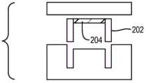
另一方面,本发明涉及使用叠层模具固定装置生产直通阀结构的方法。在不同的实施例中,叠层模具固定装置包括一个或多个销和在高度上延伸超出该销的一个或多个间隔垫,所述一个或多个销包括具有第一直径的第一层和具有小于第一直径的第二直径的第二层。大直径的第一层可包括一个或多个出口流道。该方法包括将内径匹配于第一直径的阀管安放在所述销上,例如放置在搁置于支承面上的O形环的顶部,销的第一层从该支承面延伸。另外,本发明包括将液态弹性体前驱体填充至阀管内部空间中(在将管放置在销上方之前或之后)。然后,可迫使液态弹性体前驱体从阀管内部空间离开,例如经出口流道,由此使液态弹性体的表面达到(多个)间隔垫的高度。在一些实施例中,通过将平面件放置在(多个)间隔垫上迫使液态弹性体从管内部离开。平面件可以在被放置于间隔垫上之前用诸如聚对二甲苯和金的抑制粘合-防蚀涂层涂覆。叠层模具固定装置可包括第一和第二支架件,并且(多个)销和平面件可被固定在所述第一和第二支架件之间。In another aspect, the present invention relates to a method of producing a globe valve structure using a stack mold fixture. In various embodiments, the stack mold fixture includes one or more pins and one or more spacers extending in height beyond the pins, the one or more pins including a first layer having a first diameter and a second layer having a second diameter smaller than the first diameter. The large diameter first layer may include one or more outlet flow channels. The method includes placing a valve tube with an inner diameter matching the first diameter on the pin, such as on top of an O-ring resting on a bearing surface from which a first layer of pins extends. Additionally, the present invention includes filling a liquid elastomer precursor into the valve tube interior space (either before or after placing the tube over the pin). The liquid elastomer precursor can then be forced out of the valve tube interior space, eg, through an outlet flow channel, thereby bringing the surface of the liquid elastomer to the height of the spacer(s). In some embodiments, the liquid elastomer is forced away from the interior of the tube by placing the planar member on the spacer(s). The planar pieces can be coated with a bond-and-corrosion inhibiting coating such as parylene and gold before being placed on the spacers. The lay-up mold fixture may include first and second bracket members, and the pin(s) and flat member(s) may be secured between the first and second bracket members.
本方法还包括使弹性体前驱体固化,由此在阀管中产生隔膜,隔膜厚度等于至少一个间隔垫的高度延伸超出销的距离。在一些实施例中,在平面件被放置在间隔垫上之前,在该平面件中蚀刻出凹部,进行固化,由此在隔膜中产生与该凹部形状互补的凸块。在固化过程中还可以产生从隔膜起延伸的裙部,该裙部的距离等于第一直径与第二直径之差的一半;裙部长度可以等于第二层的高度或者通过改变液态弹性体前驱体的填充体积来调整。在一些实施例中,被迫离开阀管内部空间的液态弹性体在固化之前被移除。在固化后,阀管和隔膜可从叠层模具中被移除,并且可以在阀隔膜中形成缝隙或开口。在不同的实施例中,叠层模具固定装置包括多个销;在这种情况下,该方法可涉及同时产生多个阀结构。The method also includes curing the elastomeric precursor, thereby creating a diaphragm in the valve tube, the diaphragm having a thickness equal to the distance that the height of the at least one spacer extends beyond the pin. In some embodiments, recesses are etched in the planar piece and cured before the planar piece is placed on the spacers, thereby creating bumps in the diaphragm that are complementary in shape to the recesses. It is also possible to create a skirt extending from the membrane during curing, the distance of the skirt being equal to half the difference between the first diameter and the second diameter; the skirt length can be equal to the height of the second layer or by changing the liquid elastomer precursor The fill volume of the body can be adjusted. In some embodiments, the liquid elastomer forced out of the interior space of the valve tube is removed prior to curing. After curing, the valve tube and diaphragm can be removed from the laminate mold and a gap or opening can be formed in the valve diaphragm. In various embodiments, the stack mold fixture includes multiple pins; in this case, the method may involve generating multiple valve structures simultaneously.
附图说明Description of drawings
通过以下对本发明的更详细说明,特别在结合附图的情况下将更容易理解上述内容,其中:The foregoing will be more readily understood from the following more detailed description of the invention, particularly in conjunction with the accompanying drawings, wherein:
图1是示出理想的止回阀的性能参数的流量/压力曲线;Figure 1 is a flow/pressure curve showing the performance parameters of an ideal check valve;
图2A和2B分别是根据一个实施例的基本阀结构的侧视图和立体图;2A and 2B are side and perspective views, respectively, of a basic valve structure according to one embodiment;
图2C是根据不同实施例的包括隔膜裙部的基本阀结构的侧视图;2C is a side view of a basic valve structure including a diaphragm skirt according to various embodiments;
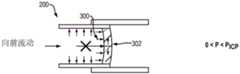
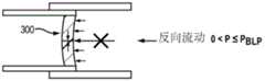
图3A-3E示出图2A和图2B的阀结构的操作;Figures 3A-3E illustrate the operation of the valve structure of Figures 2A and 2B;
图4A和4B分别是根据一个实施例的在隔膜中有密封凸块的阀结构的侧视图和立体图;4A and 4B are a side view and a perspective view, respectively, of a valve structure with sealing bumps in the diaphragm, according to one embodiment;
图5A-5D示出图4A和4B的阀结构的操作;Figures 5A-5D illustrate the operation of the valve structure of Figures 4A and 4B;
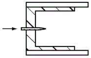
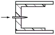
图6A和6B是根据不同实施例的具有反向渗漏止挡的阀结构的侧视图;6A and 6B are side views of a valve structure with a reverse leak stop according to various embodiments;
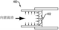
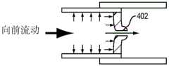
图7A-7D示出图6A的阀结构的操作;Figures 7A-7D illustrate the operation of the valve structure of Figure 6A;
图8A-8D示出图6B的阀结构的操作;Figures 8A-8D illustrate the operation of the valve structure of Figure 6B;
图9A-9D示出根据一个实施例的具有反向渗漏止挡的阀结构的操作,所述反向渗漏止挡具有偏离轴线的孔;9A-9D illustrate the operation of a valve structure having a reverse leak stop having an off-axis bore, according to one embodiment;
图9E和9F分别以立体图和侧视图示出根据一个实施例的具有对称布置的多个孔的反向渗漏止挡;Figures 9E and 9F illustrate a reverse leak stopper with symmetrically arranged multiple holes in perspective and side views, respectively, according to one embodiment;
图10A和10B分别是根据不同实施例的带有推杆的阀结构的侧视图和等距视图,所述推杆用于使阀隔膜预弯曲;Figures 10A and 10B are side and isometric views, respectively, of a valve structure with a push rod for pre-bending a valve diaphragm, according to various embodiments;
图10C是根据不同实施例的替代的阀结构的侧视图,所述阀结构具有推杆和在隔膜中的开口(而不是缝隙);10C is a side view of an alternative valve structure having a pushrod and an opening (rather than a slit) in the diaphragm, according to various embodiments;
图11A-11D示出图10B的阀结构的操作;Figures 11A-11D illustrate the operation of the valve structure of Figure 10B;
图12A-12G和图13A-13G示出根据不同实施例的通过将隔膜模制于阀管中来产生图2A和2B的阀的方法;Figures 12A-12G and Figures 13A-13G illustrate a method of producing the valve of Figures 2A and 2B by molding a diaphragm into a valve tube, according to various embodiments;
图14A-14F示出根据不同实施例的通过将预模制的隔膜附接于阀管中来产生图2A和2B的阀的方法;14A-14F illustrate a method of creating the valve of FIGS. 2A and 2B by attaching a pre-molded diaphragm in a valve tube, according to various embodiments;
图15A-15F示出根据不同实施例的通过注塑成型来产生图2A和2B的阀的方法;15A-15F illustrate a method of producing the valve of FIGS. 2A and 2B by injection molding, according to various embodiments;
图16A-16I示出根据不同实施例的通过微加工和模制来产生图2A和2B的阀的方法;16A-16I illustrate a method of producing the valve of FIGS. 2A and 2B by micromachining and molding, according to various embodiments;
图17A-17G示出根据不同实施例的通过将具有凸块的隔膜模制于阀管中来产生图4A和4B的阀的方法;17A-17G illustrate a method of producing the valve of FIGS. 4A and 4B by molding a diaphragm with bumps into a valve tube, according to various embodiments;
图18A-18F示出根据不同实施例的通过使具有凸块的隔膜注塑成型来产生图4A和4B的阀的方法;18A-18F illustrate a method of producing the valve of FIGS. 4A and 4B by injection molding a diaphragm with bumps, according to various embodiments;
图19A-19H示出根据不同实施例的通过微加工具有凸块凹部的模具且模制所述隔膜来产生图4A和4B的阀的方法;Figures 19A-19H illustrate a method of producing the valve of Figures 4A and 4B by micromachining a mold with bump recesses and molding the diaphragm, according to various embodiments;
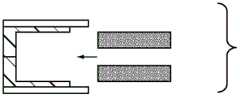
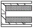
图20A-20C、图21A-21G和图22A-22G示出根据不同实施例的通过将反向渗漏止挡附接至阀管内部来产生图6A的阀的方法;Figures 20A-20C, Figures 21A-21G, and Figures 22A-22G illustrate a method of producing the valve of Figure 6A by attaching a reverse leak stop to the interior of a valve tube, according to various embodiments;
图23A-23F示出根据不同实施例的通过将推杆附接至阀管内部来产生图10A和10B的阀的方法;23A-23F illustrate a method of creating the valve of FIGS. 10A and 10B by attaching a push rod to the interior of a valve tube, according to various embodiments;
图24A是根据不同实施例的用于制造阀结构的叠层模具的透视立体图,而图24B-24D是根据本发明的用于制造阀结构的叠层模具的局部非透视图;24A is a perspective perspective view of a laminated mold for making valve structures according to various embodiments, and FIGS. 24B-24D are partial non-perspective views of a laminated mold for making valve structures in accordance with the present invention;
图24E是包括图24A-24D的叠层模具的功能销的模柱的放大图;和Figure 24E is an enlarged view of a mold post including functional pins of the stack mold of Figures 24A-24D; and
图25A-25E示出使用图24A-24E的叠层模具制造根据不同实施例的阀的方法。Figures 25A-25E illustrate a method of manufacturing a valve according to various embodiments using the stack mold of Figures 24A-24E.
具体实施方式Detailed ways
1.阀性能特征1. Valve performance characteristics
本发明涉及在各实施例中获得出色性能特征的单向止回阀。常被用于限定止回阀性能的参数如图1所示,图1描绘出常闭单向止回阀的理想流量/压力曲线。当泵送开始且压力从零向正压增长时(即压力在期望流向上具有负斜率),阀保持关闭,即流量保持为零(曲线段102),直到达到开启压力104。一旦超过开启压力104,流量就随着压力增大而增大(曲线段106)。但在使用反馈回路的泵系统中,稳态工作压力108和相应的工作流量110一旦达到则保持有效。当泵关闭时(这通常在已分配出目标给送量后发生),压力和流量减小(曲线段112)。流量通常在小于或等于开启压力104的压力114下降至零;该压力通常被称为关闭压力或停止压力。开启压力和关闭压力之间的非零差起因于在阀缝隙处相互作用的材料表面之间的静摩擦(即范德华力)。某些情况下,阀承受泵内的反压或真空(即负压),即压力逆转且变为负。如果发生这种情况,则流体流动被阻止或“截止”(曲线段116),直到达到破解压力118(或反向渗漏压)。在破解压力118情况下,阀结构的整体性被暂时或永久地破坏,允许流体反向流动(曲线段120)。The present invention relates to a one-way check valve that achieves excellent performance characteristics in various embodiments. Parameters often used to define check valve performance are shown in Figure 1, which depicts an ideal flow/pressure curve for a normally closed check valve. When pumping begins and pressure increases from zero to positive pressure (ie, pressure has a negative slope in the desired flow direction), the valve remains closed, ie, flow remains at zero (curve segment 102 ), until cracking
泵装置的控制通常考虑了泵的压力/流量特性。因此,可预测的泵操作取决于对压力/流量曲线的且特别是泵的开启压力、停止压力和破解压力的可靠了解。但可靠性对微型阀来说是很大的挑战。当利用与生产大型阀相同的技术所生产的现有技术的多组件式止回阀结构按比缩小至小于2mm的尺寸(如对于小尺寸泵装置所要求的)时,其流量/压力特性趋于变得不可重复且不可靠。另外,复杂的止回阀结构会缩短装置寿命,并且在用于长期植入的情况下可引起严重故障。例如,具有无效区或角部的复杂流体路径会致使许多传统的泵结构易于阻塞。为了应对这些挑战,本发明提供具有可再现的流量/压力性能的各种更简单的阀结构。The control of the pump unit usually takes into account the pressure/flow characteristics of the pump. Therefore, predictable pump operation depends on a reliable knowledge of the pressure/flow curve and in particular the cracking pressure, the stopping pressure and the breaking pressure of the pump. But reliability is a big challenge for microvalves. When a prior art multi-component check valve structure produced using the same technology used to produce larger valves is scaled down to a size of less than 2mm (as required for small size pump units), its flow/pressure characteristics tend to to become unrepeatable and unreliable. Additionally, complex check valve structures can shorten device life and can cause serious failures if used for long-term implantation. For example, complex fluid paths with dead zones or corners can render many conventional pump structures prone to blockage. To address these challenges, the present invention provides various simpler valve configurations with reproducible flow/pressure performance.
阀机构设计的另一项挑战源自有诸多因素影响泵运行状况,尤其是外部压力(即大气压或环境压力)波动,其会根据患者环境而变。外部压力波动会造成药泵装置或是给药过量,或是给药不足。极端情况下,外部压力突降会导致即使在泵完全关停情况下依然意外给药,因为阀在压差达到开启压力时被迫开启。患者在其正常日常生活中会经历外部压力降低的两个常见例子是在山区高速路开车或乘飞机起飞。例如在飞机起飞时,压力会下降3.8磅/平方英寸(psi)或更多。因此,为了避免故障(尤其在压力未与外压平衡的装置中,如具有刚性储器外壳的药泵装置),所植入的阀优选能承受至少3.8磅/平方英寸的压降,即,具有至少该值的开启压力。在各个实施例中,本发明能通过使阀结构具备增大阀开启压力的特征如对阀隔膜预加载的推杆来满足该要求。Another challenge in valve train design arises from the many factors that affect pump operation, particularly fluctuations in external pressure (ie, atmospheric or ambient pressure), which vary according to the patient environment. External pressure fluctuations can cause the pump device to either overdose or underdose. In extreme cases, a sudden drop in external pressure can result in accidental dosing even when the pump is completely shut down, as the valve is forced to open when the differential pressure reaches the cracking pressure. Two common examples of patients experiencing reduced external pressure in their normal daily life are driving on a mountain highway or taking off on an airplane. For example, when an airplane takes off, the pressure drops by 3.8 pounds per square inch (psi) or more. Therefore, to avoid failure (especially in devices where the pressure is not balanced with external pressure, such as a drug pump device with a rigid reservoir housing), the implanted valve is preferably capable of withstanding a pressure drop of at least 3.8 psi, i.e., Have a cracking pressure of at least this value. In various embodiments, the present invention can meet this requirement by providing the valve structure with features that increase the valve cracking pressure, such as a push rod that preloads the valve diaphragm.
除了由外压降低而导致意外打开外,泵被关停时的阀延迟关闭也能造成给药过量。主要危险时段是预计给药快要结束的这段时间,此时在储器中的气泡形成和膨胀以及外压下降的共同作用可导致药物在阀能完全关断流动之前被推出该装置,冒着严重给药过量的风险。因此,与开启压力一样,停止压力最好高于外压下降(因此接近开启压力)。在常规大型止回阀设计中,高而且可靠的停止压力能简单地通过以下方式获得,使用阀座回复机构以提供预紧力,其在阀驱动压力降至零之前早就关断了流体流动(即,达到零流量或者对于在既定应用环境中的使用目的来说是可忽略不计的预定最低流量)。通常由弹簧(如卷簧、螺旋弹簧、绳弹簧或盘簧)提供回复力。但是,这些弹簧机构同样难以小型化至亚毫米尺度,并且集成至微型止回阀的壳体中是有挑战性的。在本发明中,回复机构通过弹性隔膜提供,在各实施例中,该弹性隔膜抵靠在充当阀座的推杆或止挡结构上。In addition to accidental opening due to reduced external pressure, delayed valve closure when the pump is shut off can also result in overdose. The main dangerous period is the time near the end of the expected dosing, when the combination of bubble formation and expansion in the reservoir and a drop in external pressure can cause the drug to be pushed out of the device before the valve can completely shut off flow, risking the Risk of serious overdose. Therefore, like the cracking pressure, the stopping pressure is preferably lower than the external pressure (and thus close to the cracking pressure). In conventional large check valve designs, high and reliable stopping pressure can be achieved simply by using a seat return mechanism to provide preload that shuts off fluid flow long before the valve actuation pressure drops to zero (ie, to achieve zero flow or a predetermined minimum flow that is negligible for use in a given application environment). The restoring force is usually provided by a spring such as a coil spring, coil spring, rope spring, or coil spring. However, these spring mechanisms are also difficult to miniaturize to the sub-millimeter scale, and integration into the housing of the miniature check valve is challenging. In the present invention, the return mechanism is provided by an elastic diaphragm, which in various embodiments rests on a push rod or stop structure that acts as a valve seat.
2.阀结构和操作2. Valve structure and operation
图2A和图2B示出根据一个实施例的简单的止回阀结构。由于其简约设计,即少量零部件,故该结构可适用于微尺寸实施,同时提供准确的、可重复的和可靠的流量/压力性能。如图所示,阀200包括刚性阀管202和跨越管202的横截面的弹性体隔膜204。隔膜204在中心区域包括缝隙206,该缝隙由于静摩擦力是常闭的,但在隔膜被施压弯曲的情况下打开。隔膜相对于管直径而言通常具有在约1%至约100%之间的厚度,并可由例如硅橡胶(如羧基氯丁乳胶(LSR)、高孵化酶(HCE)、低孵化酶(LCE)等)、合成橡胶(如三元乙丙橡胶(EPDM)、丁基橡胶、丁钠橡胶等)、天然橡胶、热塑性弹性体或通常具有足够的性能和耐久性的任何粘弹性聚合材料制成。其硬度计即硬度能在隔膜生产期间通过材料成分、焙烧参数等进行调整。管可由硬聚合物(如聚醚醚酮(PEEK)、聚碳酸酯或丙烯酸)、玻璃、金属、陶瓷、硅、氧化物、复合材料或者基本上任何刚性材料制成。其尺寸(例如直径和/或长度)优选小于1mm或2mm。2A and 2B illustrate a simple check valve structure according to one embodiment. Due to its minimalistic design, ie, a small number of parts, the structure is suitable for micro-scale implementation while providing accurate, repeatable, and reliable flow/pressure performance. As shown, the
阀管202的和隔膜204的横截面可以如图所示呈圆形或具有任何各种不同的形状。例如其可以形成正方形、三角形、五边形、六边形、其它多边形(规则的或不规则的)、椭圆形等。另外,管的外横截面(由其外壁限定)可与内横截面(由内壁限定)以及隔膜204(而内横截面和隔膜通常匹配以允许隔膜适当贴靠管内壁密封)不同。例如,管可以具有有助于方便组装至泵的正方形或长方形的外横截面和促进均匀层状流体流动且避免涡流的内横截面,否则药物在所述涡流处静止。弹性体隔膜204可以在或邻近出口端(如图所示)的位置、在或邻近管202的入口端的位置、或者在管中间区域即远离管202两端的区域被连接至刚性阀管202的内表面。The cross-sections of
弹性体隔膜204可通过适当的粘接剂如硅酮胶、环氧树脂、丙烯酸粘接剂等被粘接至阀管202内部。粘接剂的选择通常取决于隔膜206的材料。例如助粘剂可被用于硅橡胶隔膜,环氧树脂适于热塑性隔膜或合成橡胶隔膜,而丙烯酸粘接剂对于1-苯基-3-甲基-4-甲基丙烯酰基-5-吡唑酮(PMMP)隔膜是优选的。或者,通过在适当位置使弹性体前驱体固化以形成隔膜可影响隔膜粘接;在这种情况下,隔膜204或是直接粘接至阀管202,或是通过涂覆在阀管202内表面上的一层助粘剂粘接至阀管202。通常,可采用任何类型的结合技术;合适的技术包括例如热结合、超声结合、红外线(IR)结合、等离子体结合等。在一些实施例中,结合表面由隔膜的周边和厚度来限定(如所示的);在其它实施例中,结合表面通过管状“裙部”208被扩大,该裙部与隔膜204周边一体形成并从隔膜周边延伸出。这样的裙部208具有进一步阻止渗漏的附加优点,因为其增大了阀管202与隔膜204之间的、任何渗漏流体必然经过的接触部的面积。在一个实施例中,刚性管202具有穿过裙部208附近的壁部的多个孔,所述孔允许环氧树脂或其它胶粘剂流过以产生在阀管202与裙部208之间的互锁界面。为了更清楚起见,下文所述的各种阀结构被描绘为没有裙部;但应该明白,这些结构可被直接改为包括从隔膜延伸出的裙部。The
图3A-3E概念性地示出止回阀200的操作,其如图所示可被插入至外管(为便于说明起见仅示出其一部分)。如果压力被施加至隔膜的上游侧300(即在向前流动方向上),则刚性阀管为弹性体隔膜提供固定的边界,从容使隔膜弯曲且隔膜内的内应力增大(图3A)。当达到阀的开启压力Pcr时,内应力开始超过缝隙周围的最大静摩擦力并且阀“裂张打开”(图3B),允许加压流体(如药液)经由阀开口到达下游区域。打开缝隙的间隙宽度对流体提供流动阻力,其大致与隔膜弯曲程度成比例。原则上,驱动压力越高,隔膜弯曲越大,并且间隙会变得越宽。因此,通常驱动压力越高,药物流量越大。3A-3E conceptually illustrate the operation of the
当压力下降时,流量减小,直到阀开口重新关闭(图3C)。在正压力Pcl下发生该关闭行为是源于隔膜在低应力水平下在固定边界条件下弯曲,这对于熟悉板壳力学基本原理的人来说是众所周知的现象。如果反向施压(即在隔膜204的下游侧302的反压或者如果在上游形成真空压力,例如随着药物被泵出而在储器中形成真空压力),则隔膜204反向弯曲(图3D)。缝隙206首先保持关闭,阻止流体反向流动。但如果压力继续增大,则在反向压力达到破解压力Pbd(如果该阀中包括有破坏构型对称性的附加结构特征如在下文中讨论的凸块或反向渗漏止挡,则破解压力通常与开启压力不同)时该阀被迫开启(图3E)。When the pressure drops, the flow decreases until the valve opening closes again (Figure 3C). This closing behavior under positive pressurePcl arises from the bending of the diaphragm under fixed boundary conditions at low stress levels, a phenomenon well known to those familiar with the fundamentals of plate-shell mechanics. If reverse pressure is applied (ie, back pressure on the
图4A和图4B示出改进的止回阀400,由于形成在隔膜404下游侧的“密封凸块”或凸部402,止回阀400相比于图2A和图2B的止回阀200能承受来自下游区的更高反压。在本实施例中,缝隙406形成在凸块402内(即与凸块402同位置),使得凸块402在反压下增大缝隙界面的密封力,从而增大破解压力(抛开密封凸块402不算,阀400与前述阀200具有相似的结构)。图5A-5D示出阀400的操作。特别是,图5C和图5D示出施加于隔膜的反压如何趋于压缩凸块402,从而增大缝隙界面处的密封力,造成明显更高的破解压力性能。尽管示出为半球状,但凸块402还可以成形为半椭圆形、半抛物体形、方块形、角锥形、棱柱形、圆锥形体等。重要的是,该凸块应整体呈凸状,以实现期望的增大的密封力;而具体形状并不重要。FIGS. 4A and 4B show an
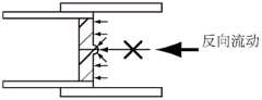
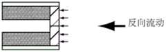
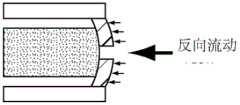
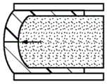
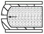
图6A和图6B示出阀的实施例600、601,其除了刚性管202和隔膜204外还包括靠近隔膜204上游侧的结构602或604,其阻止隔膜204反向弯曲并由此增大破解压力和/或此外消除或减轻反向渗漏(包括例如透过隔膜材料本身的流体渗漏)。在图6A中,“抗弯结构”或“反向渗漏止挡”602包括或由如下的管构成,管的外径适配于主阀管202的内径,而管的内径限定出与隔膜缝隙206对准的孔603。或者,抗弯结构可延伸至阀管202外部。例如在图6B中,抗弯结构604与阀上游的管606整体形成,并包括跨越外管606的横截面且紧邻隔膜204的壁608,所述隔膜在该实施例中位于阀管202的入口端。穿过抗弯结构604的壁608的中心开口或孔609与隔膜204中的缝隙206对准以允许阀601打开并允许流体通过。抗弯结构602、604可由聚合物、玻璃、金属、陶瓷、硅、氧化物、复合材料或其它材料制成并可以具有比阀管202更大或更小的刚度。Figures 6A and 6B show valve embodiments 600, 601 that, in addition to
反向渗漏止挡602、604提供抵抗止回阀隔膜204反向弯曲的支承结构,由此增大反向渗漏压。具体说,参见图6A的结构602,止挡管与隔膜的上游表面接触(虽然以零或接近零的接触力)。当反压被施加于隔膜204时,隔膜弯曲被限制到止挡管内径中的区域,而隔膜外环的弯曲被止挡限制。因此,隔膜变形受到显著制约,结果,需要高许多的反压来打开隔膜,提供了更好的反向渗漏性能。反向渗漏止挡602的工作原理如图7A-7D所示。如显而易见地,集成至上游管606中的抗弯机构604的功能相似,因为其将隔膜弯曲限制到与止挡壁608中的开口609邻近的区域,如图8A-8D所示。除阻止流体反向渗漏外,止挡还用作在向前方向上的流动限制器;其内径可根据特定流量来定制。The reverse leakage stops 602, 604 provide support structure against reverse flexing of the
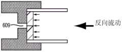
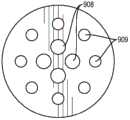
止挡602、604中的孔或开口603、609的形状和位置可被改变。在图6A和图6B的实施例中,开口是圆形的且居中位于阀管202内。在替代实施例中,孔或开口成形为例如方形、椭圆形、三角形等。另外,开口603、609可偏心就位,甚至无需与隔膜缝隙206重叠。例如图9A-9D示出包括具有偏心孔904的管状抗弯结构902的阀900。在本实施例中,由于流经该孔的流体施加了压力,故打开阀需要隔膜204充分弯曲以产生从孔开始经过止挡前表面与隔膜之间直到开启的缝隙206的流体路径。反向渗漏止挡还可具有多个孔或通孔,它们可选地具有不同的几何形状。另外,孔无需是笔直且平行于阀轴线的,而可以是例如弯曲的、锯齿形的或波浪形的。在其它实施例中,通过在此外是实心的抗弯杆中机加工出一个或多个槽来形成该孔。槽的数量和形状可改变。这种抗弯曲杆还可被中途加工成具有连接至在另一端上渐缩外直径的多个沟槽。当然,具有不同形状和尺寸的孔和/或槽可按照对本领域技术人员来说显而易见的不同方式来组合。特殊的设计布置可被调整以获得开启压力、工作流量和反向渗漏压的期望组合。多个孔或槽可用于在一个或多个路径被堵情况下提供冗余流路。在如图9E和图9F所示的止挡906的一个实施例中,不同尺寸的多个孔沿两个同心圆布置,大直径孔908围绕内圆布置,而小直径孔909围绕外圆布置。当然,孔的许多其它布置形式是可行的;优选对称的布置形式以避免偏压隔膜的一些部分而使其比其它部分更明显弯曲。另外,(多个)孔最好不与(多个)隔膜开口(或缝隙)重叠,从而该开口靠近该止挡的实心部,只要保持止挡的整体性,就阻止了任何反向渗漏。The shape and location of the holes or
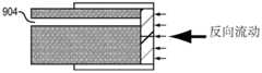
在如图10A和图10B所示的各不同实施例中,阀1000包括推杆1002,其使阀隔膜204“预弯曲”或“预紧”以提供更高的向前开启压力。可以由例如聚合物、玻璃、金属、陶瓷、硅、氧化物、复合材料或其它材料制成的推杆1002通常沿管202轴线定位于阀管202内部。如图10B所示,推杆1002可以在一个横截维度上匹配阀管202内径,从而使它能被结合至阀管202。而在另一横截维度(例如垂直的方向)上,推杆1002的宽度可以小于管202的内径,从而留出可供流体流过的空间1004。或者,推杆可以具有圆形横截面,其直径等于阀管202内径,并且包括可供流体流过的一个或多个孔或腔,允许杆径匹配于阀管内径。孔的布置可以类似于上述反向渗漏止挡的孔布置(例如在图9E和图9F中)。具有多个腔的实施方式允许在一个或多个(不是全部)腔被堵情况下保持阀的功能。腔的尺寸和与隔膜缝隙或开口的距离可被调整以改变开启压力。腔的整个横截面决定了由推杆施加的流阻;因此,推杆附加用作流动限制器。在其它的实施例中,推杆可以具有直径小于内管径的圆形横截面,并且可以悬置在具有支杆或类似结构件的阀管的内部。In the various embodiments shown in Figures 10A and 10B, the
在阀加工期间里,推杆1002被压顶在隔膜204上,迫使隔膜变形;变形程度取决于推杆1002沿阀轴线的位置,因此可通过使推杆1002移动至期望的轴向位置来控制(在加工期间)。预紧力在隔膜204与推杆1002之间形成密封。因此,为了打开阀1000,泵压须破除该密封,即克服来自推杆1002的预紧力以及隔膜缝隙的静摩擦力。因此,与图2A和图2B所示的具有平面开缝隔膜的阀200相比,推杆增大开启压力。During valve processing, the
在如图10C所示的一些推杆的实施例中,阀1006没有缝隙而是在隔膜1010中有永久开口1008,从而在施加向前压力前只有来自推杆1002的预紧力保持阀密封。所述阀中没有静摩擦力,并且一旦向前压力达到推杆1002的预紧力,则阀打开并允许药物流过其中。由于静摩擦力通常不如预紧力可靠,故该阀结构在期望非常准确的开启力时是有利的。In some pushrod embodiments as shown in FIG. 10C , the
图11A-11D示出阀1006的工作原理。当向前压力达到推杆1002的预紧力时,阀1006打开(图11A)并允许药物绕推杆1002流过阀开口1008(图11B)。而当施加反压时,推杆1002起到与上述反向渗漏止挡类似的作用并通过隔膜1010密封贴靠推杆表面来阻止回流(图11C和图11D)。在具有开缝隔膜的推杆阀(如图10A所示)中获得了在反压下的相似密封效果。为保证阀隔膜与推杆之间的良好密封,推杆优选具有非常光滑的前表面,该前表面成形为具有不变的或连续变化或平缓变化的曲率。推杆前表面可以成形为例如半球形、半椭圆形或半抛物面形等。可允许的推杆表面粗糙度和/或凹凸度通常是可容许渗漏级的函数。例如对于0.5标准升/分钟(nl/min)的渗漏限制条件来说,粗糙度通常应小于16微英寸。11A-11D illustrate the working principle of
3.生产技术3. Production technology
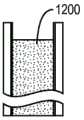
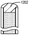
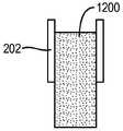
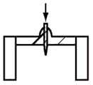
上述的微型阀能使用任何方式来生产。例如弹性体隔膜可被模制到刚性管中。在如图12A-12G所示的一个实施例中,将直径与刚性管内径相匹配的杆1200安放在管202内部,在管出口端留出用于隔膜材料的小空间(图12A)。杆1200例如可由金属(如不锈钢、黄铜、铜、铝、金、银、铂等)、塑料(如聚苯乙烯、聚丙烯、聚碳酸酯、聚醚醚酮等)、玻璃(石英玻璃、钠钙玻璃、石英等)或上述材料的组合制成。刚性管202可由玻璃、硬塑料(如聚醚醚酮、聚碳酸酯、丙烯酸等)或金属制成并且可以(但并非必须)利用助粘剂预处理以增大用于将弹性体隔膜附接至刚性管内部的结合力。在将杆1200安放在管202内后,液态弹性体前驱体1202被填充至杆1200前部的小空间中(图12B);适合的弹性体材料例子包括硅树脂(如羧基氯丁乳胶、高孵化酶、低孵化酶等)、合成橡胶(如三元乙丙橡胶、丁基橡胶、丁纳橡胶等)和天然橡胶。然后,抵靠刚性管202出口端地安置平面模件1204,以除去任何多余的前驱体(图12C)。弹性体前驱体随后在可易于被本领域技术人员确定的条件下固化,通常按照针对所选弹性体的制造商固化指导书;移除模件1204和杆1200(图12D);并用锋利刀片1208(如眼科刀片、剃须刀片、美工刀、解剖刀等)将多余的硅树脂1206从管202外部修剪掉(图12E)。固化的隔膜204随后使用小的尖锐工具如细丝、细针、电探针、眼科刀片等进行刺穿(图12F)以产生阀缝隙206(图12G)。The microvalve described above can be produced using any method. For example, an elastomeric membrane can be molded into a rigid tube. In one embodiment as shown in Figures 12A-12G, a
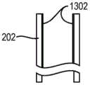
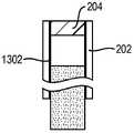
图13A-13G示出稍有改动的方法,在此,在将液态弹性体前驱体填充至形成在杆1200上方的空间(图13C)后,用刮板1300即带有柔软光滑的橡胶刀的工具除去多余前驱体,刮板随着其被拉过或推过刚性管202的顶部边缘或外表面而将多余的前驱体刮走(图13D)。弹性体随后固化(图13E)并被开缝(图13F)。图13A-13G还示出涂覆至刚性管202内表面以增强弹性体隔膜204与管202之间结合力的助粘剂层1302。Figures 13A-13G illustrate a slightly modified method where, after filling the liquid elastomer precursor into the space formed above the rod 1200 (Figure 13C), a
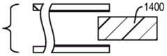
在如图14A-14F所示的又一实施例中,隔膜204被预先模制并粘接至刚性管202。实际上,这可能牵涉到将较长的弹性体柱1400预先模制在例如微型毛细管(如玻璃微量吸液管、金属微量吸液管或塑料微量吸液管)中,并将模制的弹性体柱1400插入刚性管202至符合所期望的隔膜厚度的深度(图14B)。粘胶1402(如硅树脂粘合剂、环氧树脂、丙烯酸粘合剂等)可被用在弹性体柱1400和刚性管202相配合的表面部分之间(图14C)。同样,刚性管可利用助粘剂来预处理(件图14A)以增大粘胶1402的粘接力。在粘胶固化后(图14D),弹性柱突出于刚性管202外的部分1404可用锋利切割工具被切除(图14E)。然后,隔膜可被刺穿以产生阀缝隙,如上所述。In yet another embodiment, as shown in FIGS. 14A-14F , the
在另一实施例中,使用注塑成型以在刚性阀管202中形成弹性体隔膜204,如图15A-15F所示。模具通常由金属如铝或不锈钢制成并可包括两个部分,如图15A所示;即,具有匹配并接纳刚性阀管202的凹槽的下模具部1500和平的上模具部1504。在下模具部1500中由凹槽1502限定的中心柱体1506具有上表面1508,该上表面略低于下模具部1500的上表面1509,从容当上模具部1504安装在下模具部1500上时留出浅的空腔1510(图15B)。通过注射液态弹性体,在空腔1510中形成隔膜(图15C);为此,上模具部1504和/或下模具部1502可包括使模具外部与空腔1510相连通的一个或多个孔。注入的弹性体1512在热作用下在注射模具中固化,通常是通过将其在烘箱中烘烤。对于多型腔模具,模具通常也被加压。另外,可以在注射后但在烘烤前施加真空,以尽量减少任何困在液态弹性体内的气体。固化后,将模具打开并将包括刚性管202和隔膜204在内的阀结构从模具中取出(图15D)。然后如上所述,可以通过在隔膜中形成缝隙而完成阀(图15E)。In another embodiment, injection molding is used to form the
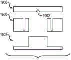
或者,弹性体隔膜阀可使用微加工模制技术来形成。在微加工模制过程中,如图16A-16I所示,可以在模制步骤前加工两个硅晶片1600、1602。上晶片1600可包括阀管202的壁和管支承结构1604,下晶片1602可包括立柱1606,立柱顶面限定隔膜204的下(即上游)表面。可采用微蚀刻将材料从硅片中除去,以产生管202的竖向侧壁轮廓以及支承结构1604和立柱1606。蚀刻过程可利用本领域技术人员所熟知的若干蚀刻技术中的任一种,包括例如深反应离子蚀刻(DRIE)、反应离子蚀刻(RIE)、光刻电铸注塑(LIGA)、激光微加工等。在加工后可将上晶片和向晶片1600、1602对准并组装(图16B)。然后,液态弹性体前驱体1608被浇到晶片组件顶部上,填充内部阀管202且包围阀管202(图16C)。可施加真空以阻止在该填充步骤期间气泡被困在液态弹性体中。然后,多余弹性体可被刮板刮除(图16E)或用其它方式除去。在固化后(图16E),移除下模具(图16F),并且通过在凹槽底端破碎或切割上晶片而轻柔地使阀脱离上晶片(图16G)。最后,用尖锐工具将模制隔膜刺穿以产生缝隙(图16H)。微加工模制方法可适用于用上晶片和下晶片1600、1602同时生产用于多个阀的多个阀结构,所述上晶片和下晶片包括阀管壁、管支承结构1604和立柱1606的。另外,与根据图15A-15F描述的注塑成型技术一样,该方法有助于通过反复使用相同模具部或晶片来可再现地生产阀。Alternatively, the elastomeric diaphragm valve can be formed using micromachining molding techniques. In a micromachining molding process, as shown in Figures 16A-16I, two
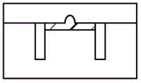
如上所述,在一些实施例中,小凸块被模制到阀隔膜中以增大阀的回流阻力(即破解压力)。如图12A-12G所示的模制方法能被直接改成产生这样的凸块,如图17A-17G所示:在将杆1200插入阀管202中并将液态弹性体前驱体填充至其上方小空间后,包括其形状与凸块互补的凹部1702(即“负凸块”)的但其它地方是平的前模具1700被抵靠管202安放以除去多余前躯体。在有前模具1700情况下固化前驱体形成了具有期望的凸块的隔膜。或者,可通过修改如图15A-15E所画出的注塑成型技术来产生凸块。如图18A-18F所示,其它地方是平的上模具部1800可仅具有“负凸块”凹部1802,其在前驱体固化后在隔膜中央形成期望的凸块。在又一实施例中,图16A-16I所示的微加工模制方法适于产生凸块。如图19A-19H所示,经改进的技术利用三个硅晶片模件:除了包括阀管和支承结构的晶片1600(在此为中间晶片)和包括限定隔膜上游表面的立柱的下晶片1602外,还设有第三上晶片1900,它在其此外平坦的底面中具有“负凸块”凹部1902。与下晶片和中间晶片中的竖向轮廓一样,上晶片1900内的凹部1902可利用如下技术被蚀刻至硅晶片,例如湿法蚀刻(利用氢氧化钾、乙二胺邻苯二酚、四甲基氢氧化铵等)、等离子蚀刻(利用氧、六氟化硫(SF6)、四氟化碳(CF4)等)或其它传统硅蚀刻技术。在加工晶片1600、1602、1900之后,将中间晶片1600和下晶片1602对准组装,并将液态弹性体前驱体浇注到该组件顶部。然后,将带有图案的上晶片1900与中间晶片和下晶片组件对准并轻柔组装至中间晶片和下晶片组件,在除去多余弹性体的同时,产生凸块(图19D)。在固化后,将该组件打开并且移除上晶片和下晶片1900、1602(图19E),并且轻柔地使阀脱离中间晶片1600。然而由于产生了凸块,固化隔膜在凸块位置被刺穿而形成阀缝隙206。As noted above, in some embodiments, small bumps are molded into the valve diaphragm to increase the valve's backflow resistance (ie, crack pressure). The molding method shown in Figures 12A-12G can be directly adapted to produce such bumps, as shown in Figures 17A-17G : after inserting the
如上所述,各不同的阀实施例包括抗弯结构(反向渗漏止挡件)以提高阀回流阻力。止挡件可通过传统技术制造(如通过从具有适当内径和外径的预制管中切割出适当长度的管段602,或者通过模制或加工更复杂的止挡结构604),随后与通过任何上述方法加工的弹性体隔膜阀机构组装在一起。参见图20A-20C,为了安装止挡管602,其被缓慢插入刚性阀管202中直到轻轻接触到隔膜204(图20A)。然后,止挡管602通过如下方式被附接至外阀管202,例如化学粘合剂(如使用环氧树脂2000、硅树脂、丙烯酸等)(如图20B所示)、机械连接(如压接、螺纹连接、成型、弹簧加载机构等)或先进的结合技术;这些和其它用于将止挡602永久附接至阀管的适当方法对本领域技术人员来说是众所周知的。在采用被整合到上游管中的止挡604的实施例中,如图6B所示,可以使用同样的结合技术将阀外部附接至管的内表面,从而止挡604紧贴隔膜204。As mentioned above, various valve embodiments include flexural structures (reverse leakage stops) to increase valve backflow resistance. The stopper can be fabricated by conventional techniques (eg, by cutting the appropriate length of
当使用反向渗漏止挡管602时,空气可能被困在止挡602与周围的刚性阀管202之间的间隙中;消除被困空气是由使用止挡602引起的一项挑战并能以不同方式来实现。在一个方法中,如图21A-21G所示,用液态弹性体前驱体2100将刚性阀管202填充至远超过既定隔膜204厚度的深度(如填充至超过其长度的一半)(图21A)。然后,其形状与阀管202互补但外径略小于阀管202内径的管状模件2102被插入阀管202中(图21B),在排出一大部分弹性体前驱体的同时,从隔膜起向下至一定距离(其上游)地填充模件2102与阀管202之间的间隙;在弹性体固化后,填充间隙的部分形成与隔膜204成一体的裙部208。然后,可以将模件2102移除(图21C),并且在隔膜204中切割出阀缝隙206(图21D)。然后,可将止挡602插入由弹性体裙部限定的空间(图21E),并且可以使用之前提到的任何结合技术使止挡602与阀管202相互结合。When reverse
图22A-22G所示的替代技术涉及迫使液态弹性体前驱体进入具有预装模件2102的刚性阀管中(图22A和图22B)。当前驱体充满在模件2102和阀管202之间间隙的期望长度时前驱体固化,并且模件2102随后被移除(图22C)。如在图21D中,止挡可随后被插入由新形成的弹性体隔膜和裙部限定的空间中并使用任何适合的结合技术结合至阀管202。An alternative technique shown in Figures 22A-22G involves forcing a liquid elastomer precursor into a rigid valve tube with a preloaded die 2102 (Figures 22A and 22B). The precursor solidifies when it fills the desired length of the gap between the
如上所述,根据本文的某些阀包括推杆,推杆安置在阀内的精确确定的轴向位置并由此使隔膜预弯曲一定程度,以获得更可靠的开启压力。这种阀可通过如下方式制造,首先,以任何上述方式将阀隔膜204模制入或以其它方式安装在刚性阀管202中,切割或刺穿隔膜204以产生缝隙206或永久开口1008,随后,缓慢小心地将推杆1002插入刚性阀管202,如分别图23A-23C所示以获得开缝隔膜和如图23D-23F所示以获得带有开口1008的隔膜。推杆1002的插入可通过具有用于准确移位控制的带有微型操纵机构的固定装置来简化;一旦推杆与隔膜204形成接触,则微型操纵机构被操作以使隔膜204移位至所期望的偏移程度(图23B和图23E)。对于特殊的期望开启压力,可解析计算或数字计算必要的偏移(如使用有限元分析)。作为替代或补充,偏移可通过对具有类似尺寸和形状的隔膜进行加载偏移试验来确定。一旦达到确定的偏移,则例如使用采用胶2300的传统结合技术、机械连接技术或先进的结合技术将推杆固定至外管(图23C和图23F)。As noted above, certain valves according to the present disclosure include push rods that sit at precisely defined axial locations within the valve and thereby pre-bend the diaphragm to some extent for more reliable cracking pressure. Such a valve may be manufactured by first molding or otherwise mounting the
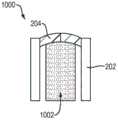
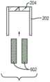
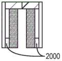
在另一替代生产方法中,叠层模具固定装置被用来以更高产量和更低成本且同时提高再现性地制造阀。该固定装置可尤其实现隔膜和裙部段的恒定厚度。另外,所制造的阀机构仅需要最小限度的加工后修整(如果有)。示例性叠层模具固定装置分别在图24A和图24B-24D中以透视图和各局部视图被示出。叠层模具固定装置2400包括四个模柱2402(其中一个在图24E中被单独示出)和用于安放在其上的平面滑板2404或类似平面件(如图24C所示)以及平行的顶部支架件2406和底部支架件2408,它们用于将柱2402和滑板2404固定在它们之间。模柱2402例如可通过加高的底部支架部2410被固定安装在底部支架2408上,而顶部支架2406可以用螺钉2412、夹子或其它机械装置被可分离连接至底部支架2408。当模具固定装置2400被组装完时,平面滑板2404被夹紧在模柱2406的上表面和顶部支架2406的底表面之间;其可通过螺钉2414被进一步固定至顶部支架。在组装状态下,顶部支架和底部支架2406、2408以相当于模柱2402高度加上滑板2404厚度的距离和/或以相当于任何支承杆2416高度的距离间隔。In another alternative production method, stack mold fixtures are used to manufacture valves with higher throughput and lower cost while improving reproducibility. The fixing means can in particular achieve a constant thickness of the diaphragm and skirt section. Additionally, the manufactured valve mechanism requires only minimal post-machining trimming, if any. Exemplary stack mold fixtures are shown in perspective and partial views in FIGS. 24A and 24B-24D, respectively. The
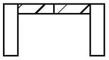
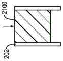
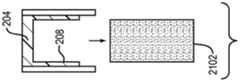
每个模柱2402包括销2418,销可被一个或多个间隔垫2420沿着与销2418同心的圆被部分围绕;间隔垫2420布置中的间隙有助于在叠层模具固定装置闭合时接近销2418。销2418构成叠层模具固定装置2400的基本功能构件,即其用作阀结构的模具。单独的阀利用每个销2418来制造;因此,销2418的数量决定利用叠层模具固定装置2400能同时制造的阀的数量。如在示出利用销和间隔垫构型生产阀的图25A-25E中所示,销2418有两层:直径与阀管内径匹配的第一层2501和直径与隔膜阀内径匹配的第二层2502,隔膜内径是在裙部内表面上的相对两点之间测量的(换句话说,隔膜内径等于隔膜外径减去裙部厚度的两倍)。当在生产过程中阀管202被置于销2418上时,第一层2501用于通过管内表面与销之间的接触将管202保持在适当位置,而较窄的第二层2502在销与管内表面之间留出用于形成隔膜裙部的空间。两个层2501、2502通常以共同轴线为中心同心设置,使得销2418与管202内表面之间的空间具有均匀厚度。第一层2501可包括一个或多个出口流道2503,气体和多余液态弹性体前驱体1202能经其流出。在一些实施例中,所用的液态弹性体前驱体量被仔细调节以产生特定裙部长度,而没有或仅有少量前驱体流出。环绕包围或局部围绕销2418的间隔垫2420在高度上延伸超出第二层2502。因此,当平面滑板2404被放置在(多个)间隔垫2520顶部上时,在销2418的上表面与(多个)间隔垫2520的上表面之间形成空隙。该空隙的高度即(多个)间隔垫2520的上表面与销2418的上表面之间的高度差等于在叠层模具固定装置2400中产生的隔膜的厚度。或者,间隔垫结构可以远离销放置以便于为了除去多余弹性体前驱体而接近销。Each
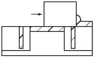
因此,为了产生阀结构,具有适当长度且内径与第一销层2501的直径相匹配的阀管202被放置在销2418上。阀管202可安放在O形环2506顶部,该O形环被置于销2418上并安放在支承面2508上,销2418从所述支承面延伸(即模柱2402的下角段2509的上表面)上,如图25B所示。O形环2506通常用于补偿阀管202的实际长度与标称长度之间的小差异,因此适应所产生的阀结构的紧公差,尽管精密生产阀管202是有难度的。通过各模柱2402上的O形环2506提供的压缩力和反作用力能保持管202全以微小高度差被压靠在平面滑板2404上。Therefore, to create the valve structure, a
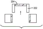
然后,刚性管202被填充液态弹性体前驱体。或者,刚性管202可在安装于销2418上之前被填充液态弹性体前驱体;在这种情况下,随着管202正在安装,弹性体前驱体从管202的内部空间中被排出并被挤压经过出口流道2503。如果需要,可以将更多的液体弹性体前驱体添加至管202的顶部。然后,平滑的滑板2404可被安放支承在(多个)间隔垫2504上,如图25D所示;因此,在销2418的上表面与滑板2404的下表面之间形成均匀厚度的弹性体层。在此过程中,任何多余液态弹性体前驱体经出口流道2503和/或在平面滑板2404与刚性管202之间被迫从管202内流出。此时,通过经在(多个)间隔垫之间或围绕(多个)间隔垫的开口接近,多余液态弹性体前驱体可被手工除去,以尽量减少加工后的修整工作。在小凸块被模制到阀隔膜以增大回流阻力的实施例中,平滑的滑板2404被蚀刻以产生其形状与期望凸块互补的凹部。另外,平滑的滑板2404可涂覆有不同材料以减弱液态弹性体粘附,从而使除去隔膜更容易;适当的粘附抑制涂层包括但不限于聚对二甲苯和喷镀金。The
为避免滑板2404与模柱2402相对运动,顶部支架件2406可被放置在平的滑板2404的顶部上(如图25E所示)并被固定至底部支架件2408。或者,平的滑板2404可在底部支架件2408被安放固定至底部支架件之前被固定至顶部支架件2406。然后,弹性体通过烘烤和根据可能针对所选类型的弹性体的制造商固化指导书的其它适当方式被固化。固化后,顶部支架件2406被移除并且刚性管202连同模制于其中的隔膜204一起被取出。最后,模制的隔膜204用尖锐工具刺穿以产生期望的阀缝隙或开口,如上文关于其它生产方法所述的那样。在包括推杆或反向渗漏止挡的实施例中,预制的杆或止挡可被插入阀结构中。To avoid relative movement of the
当然,叠层模具固定装置及其使用方法可根据如对于本领域技术人员来说显而易见的多种方式来修改。叠层模具固定装置的可行变化构型包括例如不同数量和/或布置的模柱2402;用于固定顶部和底部支架件2406、2408的不同紧固件;用于将平面滑板保持在适当位置的完全不同的支架结构或装置;不同的间隔垫构型(例如在叠层模具中心区域中的单个大型间隔垫,其允许更方便地接近所有销2418);和/或模柱2402的下角段2509的不同几何结构。另外,代替使用平面滑板2404地,可使用具有平坦底面的不同结构以产生厚度均匀的隔膜,并且顶部支架件2406的形状可被相应调整以固定所述结构。或者,可以采用不同的除去多余弹性体前驱体的方法以形成隔膜;例如,前驱体可通过刀片或滑过(多个)间隔垫2420的平面件被刮除。Of course, the stack mold fixture and method of use can be modified in various ways as will be apparent to those skilled in the art. Possible variations of the stack mold fixture include, for example, different numbers and/or arrangements of
以上已描述了本发明的各实施例,然而对本领域的普通技术人员来说显而易见的是,在不脱离本发明的精神和范围的情况下,可以采用包括本文所述概念的其它实施例。因此,以上的说明仅旨在是示例性的,而非限制性的。Various embodiments of the present invention have been described above, however, it will be apparent to those skilled in the art that other embodiments incorporating the concepts described herein may be employed without departing from the spirit and scope of the present invention. Accordingly, the above description is intended to be exemplary only, and not restrictive.
Claims (23)
Applications Claiming Priority (5)
| Application Number | Priority Date | Filing Date | Title |
|---|---|---|---|
| US201361751645P | 2013-01-11 | 2013-01-11 | |
| US61/751645 | 2013-01-11 | ||
| US201361806213P | 2013-03-28 | 2013-03-28 | |
| US61/806213 | 2013-03-28 | ||
| PCT/US2014/011301WO2014110507A2 (en) | 2013-01-11 | 2014-01-13 | Diaphragm check valves and methods of manufacture thereof |
Publications (2)
| Publication Number | Publication Date |
|---|---|
| CN105874254A CN105874254A (en) | 2016-08-17 |
| CN105874254Btrue CN105874254B (en) | 2020-07-14 |
Family
ID=50159505
Family Applications (1)
| Application Number | Title | Priority Date | Filing Date |
|---|---|---|---|
| CN201480014015.1AActiveCN105874254B (en) | 2013-01-11 | 2014-01-13 | Diaphragm check valve and manufacturing method thereof |
Country Status (7)
| Country | Link |
|---|---|
| US (1) | US9845895B2 (en) |
| EP (2) | EP2943709B1 (en) |
| JP (1) | JP6450687B2 (en) |
| CN (1) | CN105874254B (en) |
| AU (1) | AU2014205179B2 (en) |
| CA (1) | CA2898027A1 (en) |
| WO (1) | WO2014110507A2 (en) |
Families Citing this family (17)
| Publication number | Priority date | Publication date | Assignee | Title |
|---|---|---|---|---|
| US8092414B2 (en) | 2005-11-09 | 2012-01-10 | Nxstage Medical, Inc. | Diaphragm pressure pod for medical fluids |
| EP2616727B1 (en) | 2010-09-15 | 2016-04-13 | MiniPumps, LLC | Molded and packaged elastomeric check valve |
| US9551625B2 (en) | 2011-05-31 | 2017-01-24 | Nxstage Medical, Inc. | Pressure measurement devices, methods, and systems |
| EP2943709B1 (en) | 2013-01-11 | 2018-08-15 | MiniPumps, LLC | Diaphragm check valve |
| KR102296969B1 (en)* | 2014-03-21 | 2021-09-02 | 삼성전자주식회사 | Washing machine |
| JP6224296B2 (en)* | 2015-10-14 | 2017-11-01 | 柴田科学株式会社 | Check valve and diaphragm pump |
| DE102015220079A1 (en)* | 2015-10-15 | 2017-04-20 | Brose Fahrzeugteile Gmbh & Co. Kommanditgesellschaft, Bamberg | Electronics housing and manufacturing process |
| CN107780147A (en)* | 2016-08-29 | 2018-03-09 | 青岛海尔滚筒洗衣机有限公司 | Washing machine anti-spilling structure and roller washing machine |
| US11255465B2 (en)* | 2016-11-30 | 2022-02-22 | Agilent Technologies, Inc. | Microfluidic check valve and related devices and systems |
| CN108656544A (en)* | 2017-03-27 | 2018-10-16 | 三纬国际立体列印科技股份有限公司 | Three-dimensional printing spray head structure |
| CN107830298A (en)* | 2017-11-02 | 2018-03-23 | 江苏格兰特干燥浓缩设备有限公司 | A kind of evaporated crystallization device |
| CN111041777B (en)* | 2018-10-12 | 2023-05-02 | 青岛海尔洗衣机有限公司 | A breathable valve applied to a non-porous drum and a drum washing machine |
| KR20220029730A (en)* | 2019-08-30 | 2022-03-08 | 가부시키가이샤 후지킨 | diaphragm valve |
| CN111288222A (en)* | 2020-02-05 | 2020-06-16 | 鲁东大学 | A nanoscale one-way valve structure and its function simulation verification method |
| CN112295615A (en)* | 2020-05-15 | 2021-02-02 | 广州普世君安生物科技有限公司 | Micro-fluidic valve and micro-fluidic chip |
| NL2028805B1 (en)* | 2021-07-22 | 2023-01-27 | Weener Plastics Group B V | Method for manufacturing a self-closing dispensing valve. |
| US20250195859A1 (en)* | 2023-12-18 | 2025-06-19 | W. L. Gore & Associates, Inc. | Flexible resealable septum |
Citations (5)
| Publication number | Priority date | Publication date | Assignee | Title |
|---|---|---|---|---|
| US3618632A (en)* | 1969-07-31 | 1971-11-09 | Hoff Stevens | Check valve |
| CN1867795A (en)* | 2003-08-11 | 2006-11-22 | 加州理工学院 | Microfluidic large scale integration |
| CN101018965A (en)* | 2004-08-30 | 2007-08-15 | 星精密株式会社 | Check valve and diaphram pump |
| US7997463B2 (en)* | 2007-10-30 | 2011-08-16 | 3M Innovative Properties Company | Nozzle, adhesive dispenser, and method of dispensing adhesive |
| US20120211095A1 (en)* | 2010-09-15 | 2012-08-23 | Raymond Peck | Molded and Packaged Elastomeric Check Valve |
Family Cites Families (56)
| Publication number | Priority date | Publication date | Assignee | Title |
|---|---|---|---|---|
| US3307819A (en) | 1965-04-12 | 1967-03-07 | Cocito Joe Michael | Disc valve for vacuum board |
| US3608676A (en) | 1968-11-06 | 1971-09-28 | Gregory J Wieck | Reversible irrigation lines |
| US4014048A (en)* | 1975-11-24 | 1977-03-29 | The Kendall Company | Inflation device |
| US4124773A (en) | 1976-11-26 | 1978-11-07 | Robin Elkins | Audio storage and distribution system |
| US4143853A (en) | 1977-07-14 | 1979-03-13 | Metatech Corporation | Valve for use with a catheter or the like |
| US4434810A (en) | 1980-07-14 | 1984-03-06 | Vernay Laboratories, Inc. | Bi-directional pressure relief valve |
| US4343810A (en) | 1980-10-24 | 1982-08-10 | The Dow Chemical Company | Method of inhibiting sickling of sickle erythrocytes using 2-((haloanilino)methyl)-2-imidazolines |
| US4457757A (en) | 1981-07-20 | 1984-07-03 | Molteno Anthony C B | Device for draining aqueous humour |
| US4554918A (en) | 1982-07-28 | 1985-11-26 | White Thomas C | Ocular pressure relief device |
| US5171606A (en) | 1982-11-30 | 1992-12-15 | Unisys Corp. | Method of coating an optical media |
| US4636150A (en) | 1983-05-23 | 1987-01-13 | Greatbatch Enterprises, Inc. | Low power electromagnetic pump |
| US4531543A (en) | 1983-06-20 | 1985-07-30 | Ingersoll-Rand Company | Uni-directional flow, fluid valve |
| US4593720A (en)* | 1983-12-20 | 1986-06-10 | National Instrument Company, Inc. | Filling nozzle valve structure |
| NZ215409A (en) | 1986-03-07 | 1989-02-24 | Anthony Christopher Be Molteno | Implant for drainage of aqueous humour in glaucoma |
| US4867200A (en) | 1988-06-30 | 1989-09-19 | Markley George L | Unidirectional fluid flow check valve assembly |
| US5071408A (en) | 1988-10-07 | 1991-12-10 | Ahmed Abdul Mateen | Medical valve |
| US5785674A (en) | 1988-10-07 | 1998-07-28 | Mateen; Ahmed Abdul | Device and method for treating glaucoma |
| US4869282A (en) | 1988-12-09 | 1989-09-26 | Rosemount Inc. | Micromachined valve with polyimide film diaphragm |
| US5116457A (en) | 1989-04-07 | 1992-05-26 | I C Sensors, Inc. | Semiconductor transducer or actuator utilizing corrugated supports |
| US4948092A (en) | 1990-03-07 | 1990-08-14 | Royce Medical Company | Combined check valve and fluid pressure relief valve |
| ES2028513A6 (en) | 1990-05-24 | 1992-07-01 | Dirygesa Sl | Elastic valve for controlling a fluid flow |
| US5476445A (en) | 1990-05-31 | 1995-12-19 | Iovision, Inc. | Glaucoma implant with a temporary flow restricting seal |
| FR2673258B1 (en) | 1991-02-21 | 1993-05-21 | Valeo Thermique Habitacle | DEVICE FOR CONTROLLING A FLUID CURRENT INCLUDING A SHUTTERING MEMBRANE TRANSVERSELY CURRENTLY CURRENT. |
| DE9102284U1 (en) | 1991-02-27 | 1991-08-29 | Junker, Bertold, 5880 Lüdenscheid | Check diaphragms for use in a wide range of housings (for mechanical and plant engineering as well as in the medical sector) |
| US5454796A (en) | 1991-04-09 | 1995-10-03 | Hood Laboratories | Device and method for controlling intraocular fluid pressure |
| US5490220A (en) | 1992-03-18 | 1996-02-06 | Knowles Electronics, Inc. | Solid state condenser and microphone devices |
| US5261459A (en)* | 1992-12-07 | 1993-11-16 | Vernay Laboratories, Inc. | Miniature duckbill valve having a low cracking pressure and high flow rate |
| US5265415A (en) | 1993-01-27 | 1993-11-30 | The United States Of America As Represented By The Administrator Of The National Aeronautics And Space Administration | Liquid fuel injection elements for rocket engines |
| DE69431994T2 (en) | 1993-10-04 | 2003-10-30 | Res Int Inc | MICRO-MACHINED FLUID TREATMENT DEVICE WITH FILTER AND CONTROL VALVE |
| US5727594A (en) | 1995-02-09 | 1998-03-17 | Choksi; Pradip | Low actuation pressure unidirectional flow valve |
| US6136212A (en) | 1996-08-12 | 2000-10-24 | The Regents Of The University Of Michigan | Polymer-based micromachining for microfluidic devices |
| WO1998014707A1 (en) | 1996-10-03 | 1998-04-09 | Westonbridge International Limited | Micro-machined device for fluids and method of manufacture |
| US6612535B1 (en) | 1997-01-24 | 2003-09-02 | California Institute Of Technology | MEMS valve |
| US6069392A (en) | 1997-04-11 | 2000-05-30 | California Institute Of Technology | Microbellows actuator |
| US6092611A (en) | 1997-05-28 | 2000-07-25 | Dresser Industries, Inc. | Encapsulated elastomeric relief valve |
| US6241904B1 (en) | 1997-07-15 | 2001-06-05 | Silverbrook Research Pty Ltd | Method of manufacture of a two plate reverse firing electromagnetic ink jet printer |
| EP0903179A1 (en) | 1997-09-18 | 1999-03-24 | Metrohm Ag | Microvalve |
| WO1999024744A1 (en) | 1997-11-12 | 1999-05-20 | California Institute Of Technology | Micromachined parylene membrane valve and pump |
| US6126273A (en) | 1998-04-30 | 2000-10-03 | Hewlett-Packard Co. | Inkjet printer printhead which eliminates unpredictable ink nucleation variations |
| US6240962B1 (en) | 1998-11-16 | 2001-06-05 | California Institute Of Technology | Parylene micro check valve and fabrication method thereof |
| US6202766B1 (en) | 1999-03-24 | 2001-03-20 | William L. Shepherd | Relief valve |
| AU7716800A (en) | 1999-09-24 | 2001-04-24 | California Institute Of Technology | A normally closed in-channel micro check valve |
| US6334761B1 (en) | 2000-03-02 | 2002-01-01 | California Institute Of Technology | Check-valved silicon diaphragm pump and method of fabricating the same |
| KR100422364B1 (en) | 2001-11-19 | 2004-03-11 | 삼성광주전자 주식회사 | Exhaust valve of sealed type compressor |
| US6554591B1 (en) | 2001-11-26 | 2003-04-29 | Motorola, Inc. | Micropump including ball check valve utilizing ceramic technology and method of fabrication |
| US6739576B2 (en) | 2001-12-20 | 2004-05-25 | Nanostream, Inc. | Microfluidic flow control device with floating element |
| AU2003253998A1 (en) | 2002-07-26 | 2004-02-16 | Applera Corporation | One-directional microball valve for a microfluidic device |
| US6874999B2 (en) | 2002-08-15 | 2005-04-05 | Motorola, Inc. | Micropumps with passive check valves |
| US7025740B2 (en) | 2003-04-22 | 2006-04-11 | Ahmed A Mateen | Device for treating glaucoma & method of manufacture |
| JP2006214837A (en) | 2005-02-02 | 2006-08-17 | Sekisui Chem Co Ltd | Microvalve |
| US20060247664A1 (en) | 2005-03-08 | 2006-11-02 | California Institute Of Technology | Micromachined tissue anchors for securing implants without sutures |
| ES2533901T3 (en) | 2006-08-10 | 2015-04-15 | California Institute Of Technology | Microfluidic valves with floating element and manufacturing procedure |
| DE102008045423A1 (en) | 2008-09-02 | 2010-03-04 | Scienion Ag | Pressure actuator, in particular ventilation valve for venting a microdispenser |
| US8276616B2 (en) | 2009-03-20 | 2012-10-02 | Xylem Ip Holdings Llc | High pressure duckbill valve and insert |
| US20120241017A1 (en) | 2011-03-22 | 2012-09-27 | Jeffrey Chun-Hui Lin | Microfluidic Check Valves With Enhanced Cracking Pressures and Methods of Making the Same |
| EP2943709B1 (en) | 2013-01-11 | 2018-08-15 | MiniPumps, LLC | Diaphragm check valve |
- 2014
- 2014-01-13EPEP14706352.3Apatent/EP2943709B1/enactiveActive
- 2014-01-13AUAU2014205179Apatent/AU2014205179B2/enactiveActive
- 2014-01-13WOPCT/US2014/011301patent/WO2014110507A2/enactiveApplication Filing
- 2014-01-13EPEP18176869.8Apatent/EP3396220B1/enactiveActive
- 2014-01-13CNCN201480014015.1Apatent/CN105874254B/enactiveActive
- 2014-01-13USUS14/153,662patent/US9845895B2/enactiveActive
- 2014-01-13CACA2898027Apatent/CA2898027A1/ennot_activeAbandoned
- 2014-01-13JPJP2015552857Apatent/JP6450687B2/enactiveActive
Patent Citations (5)
| Publication number | Priority date | Publication date | Assignee | Title |
|---|---|---|---|---|
| US3618632A (en)* | 1969-07-31 | 1971-11-09 | Hoff Stevens | Check valve |
| CN1867795A (en)* | 2003-08-11 | 2006-11-22 | 加州理工学院 | Microfluidic large scale integration |
| CN101018965A (en)* | 2004-08-30 | 2007-08-15 | 星精密株式会社 | Check valve and diaphram pump |
| US7997463B2 (en)* | 2007-10-30 | 2011-08-16 | 3M Innovative Properties Company | Nozzle, adhesive dispenser, and method of dispensing adhesive |
| US20120211095A1 (en)* | 2010-09-15 | 2012-08-23 | Raymond Peck | Molded and Packaged Elastomeric Check Valve |
Also Published As
| Publication number | Publication date |
|---|---|
| EP2943709A2 (en) | 2015-11-18 |
| CN105874254A (en) | 2016-08-17 |
| CA2898027A1 (en) | 2014-07-17 |
| AU2014205179B2 (en) | 2018-08-09 |
| WO2014110507A3 (en) | 2015-02-26 |
| EP2943709B1 (en) | 2018-08-15 |
| JP6450687B2 (en) | 2019-01-09 |
| EP3396220A1 (en) | 2018-10-31 |
| US20140196798A1 (en) | 2014-07-17 |
| AU2014205179A1 (en) | 2015-07-30 |
| EP3396220B1 (en) | 2020-10-14 |
| WO2014110507A2 (en) | 2014-07-17 |
| JP2016504547A (en) | 2016-02-12 |
| US9845895B2 (en) | 2017-12-19 |
Similar Documents
| Publication | Publication Date | Title |
|---|---|---|
| CN105874254B (en) | Diaphragm check valve and manufacturing method thereof | |
| EP2077888B1 (en) | Micro-valve | |
| US10502331B2 (en) | One way valve | |
| CN102762242A (en) | Micromechanic passive flow regulator | |
| US10240689B2 (en) | Diaphragm check valves and methods of manufacture thereof | |
| AU2007310633B2 (en) | Micro-valve |
Legal Events
| Date | Code | Title | Description |
|---|---|---|---|
| C06 | Publication | ||
| PB01 | Publication | ||
| C10 | Entry into substantive examination | ||
| SE01 | Entry into force of request for substantive examination | ||
| GR01 | Patent grant | ||
| GR01 | Patent grant |