CN105873630B - Device and method for assisted respiration by transvascular nerve stimulation - Google Patents
Device and method for assisted respiration by transvascular nerve stimulationDownload PDFInfo
- Publication number
- CN105873630B CN105873630BCN201480071819.5ACN201480071819ACN105873630BCN 105873630 BCN105873630 BCN 105873630BCN 201480071819 ACN201480071819 ACN 201480071819ACN 105873630 BCN105873630 BCN 105873630B
- Authority
- CN
- China
- Prior art keywords
- catheter
- electrode
- distal
- electrodes
- proximal
- Prior art date
- Legal status (The legal status is an assumption and is not a legal conclusion. Google has not performed a legal analysis and makes no representation as to the accuracy of the status listed.)
- Active
Links
Images


Classifications
- A—HUMAN NECESSITIES
- A61—MEDICAL OR VETERINARY SCIENCE; HYGIENE
- A61N—ELECTROTHERAPY; MAGNETOTHERAPY; RADIATION THERAPY; ULTRASOUND THERAPY
- A61N1/00—Electrotherapy; Circuits therefor
- A61N1/18—Applying electric currents by contact electrodes
- A61N1/32—Applying electric currents by contact electrodes alternating or intermittent currents
- A61N1/36—Applying electric currents by contact electrodes alternating or intermittent currents for stimulation
- A61N1/3601—Applying electric currents by contact electrodes alternating or intermittent currents for stimulation of respiratory organs
- A—HUMAN NECESSITIES
- A61—MEDICAL OR VETERINARY SCIENCE; HYGIENE
- A61B—DIAGNOSIS; SURGERY; IDENTIFICATION
- A61B5/00—Measuring for diagnostic purposes; Identification of persons
- A61B5/02—Detecting, measuring or recording for evaluating the cardiovascular system, e.g. pulse, heart rate, blood pressure or blood flow
- A61B5/024—Measuring pulse rate or heart rate
- A61B5/0245—Measuring pulse rate or heart rate by using sensing means generating electric signals, i.e. ECG signals
- A—HUMAN NECESSITIES
- A61—MEDICAL OR VETERINARY SCIENCE; HYGIENE
- A61B—DIAGNOSIS; SURGERY; IDENTIFICATION
- A61B5/00—Measuring for diagnostic purposes; Identification of persons
- A61B5/24—Detecting, measuring or recording bioelectric or biomagnetic signals of the body or parts thereof
- A61B5/25—Bioelectric electrodes therefor
- A61B5/279—Bioelectric electrodes therefor specially adapted for particular uses
- A61B5/28—Bioelectric electrodes therefor specially adapted for particular uses for electrocardiography [ECG]
- A61B5/283—Invasive
- A61B5/287—Holders for multiple electrodes, e.g. electrode catheters for electrophysiological study [EPS]
- A—HUMAN NECESSITIES
- A61—MEDICAL OR VETERINARY SCIENCE; HYGIENE
- A61B—DIAGNOSIS; SURGERY; IDENTIFICATION
- A61B5/00—Measuring for diagnostic purposes; Identification of persons
- A61B5/68—Arrangements of detecting, measuring or recording means, e.g. sensors, in relation to patient
- A61B5/6846—Arrangements of detecting, measuring or recording means, e.g. sensors, in relation to patient specially adapted to be brought in contact with an internal body part, i.e. invasive
- A61B5/6847—Arrangements of detecting, measuring or recording means, e.g. sensors, in relation to patient specially adapted to be brought in contact with an internal body part, i.e. invasive mounted on an invasive device
- A61B5/6852—Catheters
- A—HUMAN NECESSITIES
- A61—MEDICAL OR VETERINARY SCIENCE; HYGIENE
- A61M—DEVICES FOR INTRODUCING MEDIA INTO, OR ONTO, THE BODY; DEVICES FOR TRANSDUCING BODY MEDIA OR FOR TAKING MEDIA FROM THE BODY; DEVICES FOR PRODUCING OR ENDING SLEEP OR STUPOR
- A61M25/00—Catheters; Hollow probes
- A—HUMAN NECESSITIES
- A61—MEDICAL OR VETERINARY SCIENCE; HYGIENE
- A61M—DEVICES FOR INTRODUCING MEDIA INTO, OR ONTO, THE BODY; DEVICES FOR TRANSDUCING BODY MEDIA OR FOR TAKING MEDIA FROM THE BODY; DEVICES FOR PRODUCING OR ENDING SLEEP OR STUPOR
- A61M25/00—Catheters; Hollow probes
- A61M25/0021—Catheters; Hollow probes characterised by the form of the tubing
- A61M25/0023—Catheters; Hollow probes characterised by the form of the tubing by the form of the lumen, e.g. cross-section, variable diameter
- A61M25/0026—Multi-lumen catheters with stationary elements
- A61M25/0029—Multi-lumen catheters with stationary elements characterized by features relating to least one lumen located at the middle part of the catheter, e.g. slots, flaps, valves, cuffs, apertures, notches, grooves or rapid exchange ports
- A—HUMAN NECESSITIES
- A61—MEDICAL OR VETERINARY SCIENCE; HYGIENE
- A61M—DEVICES FOR INTRODUCING MEDIA INTO, OR ONTO, THE BODY; DEVICES FOR TRANSDUCING BODY MEDIA OR FOR TAKING MEDIA FROM THE BODY; DEVICES FOR PRODUCING OR ENDING SLEEP OR STUPOR
- A61M25/00—Catheters; Hollow probes
- A61M25/01—Introducing, guiding, advancing, emplacing or holding catheters
- A61M25/0105—Steering means as part of the catheter or advancing means; Markers for positioning
- A61M25/0133—Tip steering devices
- A61M25/0147—Tip steering devices with movable mechanical means, e.g. pull wires
- A—HUMAN NECESSITIES
- A61—MEDICAL OR VETERINARY SCIENCE; HYGIENE
- A61N—ELECTROTHERAPY; MAGNETOTHERAPY; RADIATION THERAPY; ULTRASOUND THERAPY
- A61N1/00—Electrotherapy; Circuits therefor
- A61N1/02—Details
- A61N1/04—Electrodes
- A61N1/05—Electrodes for implantation or insertion into the body, e.g. heart electrode
- A61N1/0551—Spinal or peripheral nerve electrodes
- A—HUMAN NECESSITIES
- A61—MEDICAL OR VETERINARY SCIENCE; HYGIENE
- A61N—ELECTROTHERAPY; MAGNETOTHERAPY; RADIATION THERAPY; ULTRASOUND THERAPY
- A61N1/00—Electrotherapy; Circuits therefor
- A61N1/18—Applying electric currents by contact electrodes
- A61N1/32—Applying electric currents by contact electrodes alternating or intermittent currents
- A61N1/36—Applying electric currents by contact electrodes alternating or intermittent currents for stimulation
- A61N1/3605—Implantable neurostimulators for stimulating central or peripheral nerve system
- A61N1/3606—Implantable neurostimulators for stimulating central or peripheral nerve system adapted for a particular treatment
- A61N1/3611—Respiration control
- A—HUMAN NECESSITIES
- A61—MEDICAL OR VETERINARY SCIENCE; HYGIENE
- A61N—ELECTROTHERAPY; MAGNETOTHERAPY; RADIATION THERAPY; ULTRASOUND THERAPY
- A61N1/00—Electrotherapy; Circuits therefor
- A61N1/18—Applying electric currents by contact electrodes
- A61N1/32—Applying electric currents by contact electrodes alternating or intermittent currents
- A61N1/36—Applying electric currents by contact electrodes alternating or intermittent currents for stimulation
- A61N1/3605—Implantable neurostimulators for stimulating central or peripheral nerve system
- A61N1/36128—Control systems
- A61N1/36146—Control systems specified by the stimulation parameters
- A61N1/36182—Direction of the electrical field, e.g. with sleeve around stimulating electrode
- A61N1/36185—Selection of the electrode configuration
- A—HUMAN NECESSITIES
- A61—MEDICAL OR VETERINARY SCIENCE; HYGIENE
- A61B—DIAGNOSIS; SURGERY; IDENTIFICATION
- A61B2562/00—Details of sensors; Constructional details of sensor housings or probes; Accessories for sensors
- A61B2562/04—Arrangements of multiple sensors of the same type
- A61B2562/043—Arrangements of multiple sensors of the same type in a linear array
- A—HUMAN NECESSITIES
- A61—MEDICAL OR VETERINARY SCIENCE; HYGIENE
- A61M—DEVICES FOR INTRODUCING MEDIA INTO, OR ONTO, THE BODY; DEVICES FOR TRANSDUCING BODY MEDIA OR FOR TAKING MEDIA FROM THE BODY; DEVICES FOR PRODUCING OR ENDING SLEEP OR STUPOR
- A61M25/00—Catheters; Hollow probes
- A61M25/0021—Catheters; Hollow probes characterised by the form of the tubing
- A61M25/0023—Catheters; Hollow probes characterised by the form of the tubing by the form of the lumen, e.g. cross-section, variable diameter
- A61M25/0026—Multi-lumen catheters with stationary elements
- A61M2025/0034—Multi-lumen catheters with stationary elements characterized by elements which are assembled, connected or fused, e.g. splittable tubes, outer sheaths creating lumina or separate cores
Landscapes
- Health & Medical Sciences (AREA)
- Life Sciences & Earth Sciences (AREA)
- Engineering & Computer Science (AREA)
- Animal Behavior & Ethology (AREA)
- Biomedical Technology (AREA)
- General Health & Medical Sciences (AREA)
- Public Health (AREA)
- Veterinary Medicine (AREA)
- Heart & Thoracic Surgery (AREA)
- Radiology & Medical Imaging (AREA)
- Nuclear Medicine, Radiotherapy & Molecular Imaging (AREA)
- Cardiology (AREA)
- Biophysics (AREA)
- Pulmonology (AREA)
- Neurology (AREA)
- Neurosurgery (AREA)
- Molecular Biology (AREA)
- Physics & Mathematics (AREA)
- Pathology (AREA)
- Medical Informatics (AREA)
- Surgery (AREA)
- Physiology (AREA)
- Hematology (AREA)
- Anesthesiology (AREA)
- Orthopedic Medicine & Surgery (AREA)
- Signal Processing (AREA)
- Mechanical Engineering (AREA)
- Electrotherapy Devices (AREA)
- Measurement And Recording Of Electrical Phenomena And Electrical Characteristics Of The Living Body (AREA)
Abstract
Description
Translated fromChinese相关申请的交叉引用CROSS-REFERENCE TO RELATED APPLICATIONS
本申请要求35U.S.C.§119(e)下的2013年11月22日提交的标题为“Apparatus forAssisted Breathing by Transvascular Nerve Stimulation and Related Methods”的美国临时专利申请No.61/907,993的权益。’993临时申请的全部公开内容通过引用被结合于此。This application claims the benefit of US Provisional Patent Application No. 61/907,993, filed November 22, 2013, under 35 U.S.C. § 119(e), entitled "Apparatus for Assisted Breathing by Transvascular Nerve Stimulation and Related Methods." The entire disclosure of the '993 provisional application is incorporated herein by reference.
技术领域technical field
本公开内容的实施例涉及医疗装置并且尤其涉及适用于减弱的神经生理功能的修复、增强或调制的装置。具体实施例提供了用于通过神经的经血管电刺激刺激隔膜肌以帮助呼吸的装置。Embodiments of the present disclosure relate to medical devices and, in particular, to devices suitable for the repair, enhancement, or modulation of diminished neurophysiological function. Particular embodiments provide devices for stimulating the diaphragm muscle through transvascular electrical stimulation of nerves to aid in breathing.
背景技术Background technique
神经的电刺激被广泛应用在各种条件的治疗中并且可以被应用到控制肌肉活动或生成感觉。可以通过在神经当中、周围或附近放置电极并且通过电力的植入或外部源激活电极来刺激神经。Electrical stimulation of nerves is widely used in the treatment of various conditions and can be applied to control muscle activity or generate sensation. Nerves can be stimulated by placing electrodes in, around or near the nerve and activating the electrodes by implantation of electrical power or by an external source.
膈神经通常从大脑发送引起呼吸所必需的隔膜收缩的信号。但是,各种条件会阻止适当的信号被传递到膈神经。这些包括:The phrenic nerve normally sends signals from the brain that cause the diaphragm to contract, which is necessary for breathing. However, various conditions prevent proper signals from being delivered to the phrenic nerve. These include:
●影响脊髓或脑干的永久或暂时损伤或疾病;permanent or temporary injury or disease affecting the spinal cord or brain stem;
●肌萎缩性侧索硬化症(ALS);Amyotrophic lateral sclerosis (ALS);
●减少的白天或晚上通气驱力(例如,中枢性睡眠呼吸暂停,気症候群(Ondine’scurse));及Reduced daytime or nighttime ventilatory drive (eg, central sleep apnea, Ondine'scurse); and
●在麻醉剂和/或机械通气的影响下减少的通气驱力。• Reduced ventilatory drive under the influence of anesthetics and/or mechanical ventilation.
这些条件影响显著数量的人。These conditions affect a significant number of people.
插管和正压力机械通气(MV)可被使用几个小时或几天,有时几周的时间段,以帮助危重患者在重症监护病房(ICU)中时呼吸。有些患者可能无法恢复自主呼吸并且因此需要延长的或永久的机械通气。虽然机械通气最初可以救生,但它有各种显著问题和/或副作用。机械通气:Intubation and positive pressure mechanical ventilation (MV) can be used for periods of hours or days, sometimes weeks, to help critically ill patients breathe while in the intensive care unit (ICU). Some patients may not be able to resume spontaneous breathing and therefore require prolonged or permanent mechanical ventilation. While mechanical ventilation is initially life-saving, it has various significant problems and/or side effects. Mechanical Ventilation:
●常常引起呼吸机所致肺损伤(VILI)和肺泡损伤,这会导致流体在肺中的积累和增加的对感染的易感性(呼吸机关联的肺炎;VAP);Often causes ventilator-induced lung injury (VILI) and alveolar damage, which can lead to fluid accumulation in the lungs and increased susceptibility to infection (ventilator-associated pneumonia; VAP);
●通常需要镇静,以减少急性插管患者的不适和焦虑;sedation is often required to reduce discomfort and anxiety in acutely intubated patients;
●引起废用隔膜肌的快速萎缩(呼吸机所致隔膜功能障碍,VIDD);Causes rapid atrophy of the disused diaphragm muscle (ventilator-induced diaphragm dysfunction, VIDD);
●因为肺被加压并且隔膜是不活动的,所以会不利地影响静脉回流;venous return is adversely affected because the lungs are pressurized and the diaphragm is inactive;
●干扰进食和说话;● interfere with eating and speaking;
●要求不便于携带的装置;及● requiring devices that are not portable; and
●如果患者未恢复正常呼吸并变成依赖呼吸机,则增加了死亡的风险。● Increased risk of death if patient does not resume normal breathing and becomes ventilator dependent.
被镇静并连接到机械呼吸机的患者不能正常呼吸,因为对隔膜和辅助呼吸肌的中枢神经驱动被抑制。不活动导致肌肉废用性萎缩和健康(well-being)的整体下降。隔膜肌萎缩迅速发生并且对患者会是严重的问题。根据所发表的器官捐赠患者的研究(Levine等人,New England Journal of Medicine,358:1327-1335,2008年),机械通气仅仅18至69小时后,所有的隔膜肌纤维就已经收缩平均52-57%。肌纤维萎缩导致肌无力和增加的疲劳性。因此,呼吸机所致隔膜萎缩会导致患者变成依赖呼吸机。据报道,在美国、欧洲和加拿大每年有超过840000ICU患者变成依赖呼吸机。Patients who are sedated and connected to a mechanical ventilator cannot breathe normally because the central nervous drive to the diaphragm and accessory respiratory muscles is inhibited. Inactivity leads to muscle disuse atrophy and an overall decrease in well-being. Diaphragmatic muscle atrophy occurs rapidly and can be a serious problem for the patient. According to a published study of organ donation patients (Levine et al., New England Journal of Medicine, 358: 1327-1335, 2008), after only 18 to 69 hours of mechanical ventilation, all diaphragm muscle fibers have contracted on average 52-57 %. Muscle fiber atrophy results in muscle weakness and increased fatigue. Therefore, ventilator-induced diaphragm atrophy can cause the patient to become ventilator-dependent. More than 840,000 ICU patients are reported to become ventilator-dependent each year in the United States, Europe and Canada.
仍需要可用于刺激呼吸的成本有效、实用、手术简单和微创性的装置和方法。还需要用于促进MV上的患者恢复自然呼吸并脱离MV的能力的装置和方法。There remains a need for cost-effective, practical, surgically simple, and minimally invasive devices and methods that can be used to stimulate breathing. There is also a need for devices and methods for promoting a patient on an MV to regain the ability to breathe naturally and out of the MV.
发明内容SUMMARY OF THE INVENTION
除其它事项外,本公开内容的实施例涉及用于神经刺激的医疗装置和方法。具体实施例提供用于通过神经的经血管电刺激刺激呼吸的装置。本文中所公开的实施例中的每种可以包括联系其它公开的实施例中的任一所描述的特征中的一个或多个。Among other things, embodiments of the present disclosure relate to medical devices and methods for nerve stimulation. Particular embodiments provide devices for stimulating respiration through transvascular electrical stimulation of nerves. Each of the embodiments disclosed herein may include one or more of the features described in connection with any of the other disclosed embodiments.
在一种实施例中,导管可以包括细长的管状构件,该细长的管状构件包括每个都在细长的管状构件的外壁中的第一孔和第二孔;第一电极,其位于细长的管状构件内并且相对于第一孔定位,使得与第一电极关联的电能通过第一孔行进到细长的管状构件外部或从其行进;以及第二电极,其位于细长的管状构件内并且相对于第二孔定位,使得与第二电极关联的电能通过第二孔行进到细长的管状构件的外部或从其行进。In one embodiment, the catheter may include an elongated tubular member including a first aperture and a second aperture each in an outer wall of the elongated tubular member; a first electrode located at within the elongated tubular member and positioned relative to the first aperture such that electrical energy associated with the first electrode travels through the first aperture to or from outside the elongated tubular member; and a second electrode located in the elongated tubular member The member is positioned within and relative to the second aperture such that electrical energy associated with the second electrode travels through the second aperture to or from the exterior of the elongated tubular member.
导管可以附加地或选择性地包括以下特征中的一个或多个:与导管的纵轴垂直的平面可以穿过第一和第二孔两者;与导管的纵轴垂直并穿过第一孔的平面不穿过第二孔;与导管的纵轴平行的线可以穿过第一和第二孔二者;导管还可以包括每个都在细长的管状构件的外壁中的第三孔和第四孔,位于导管的远端附近,并且第一和第二孔可以位于第三和第四孔近侧,第三电极位于细长的管状构件内并且相对于第三孔定位,使得与第三电极关联的电能通过第三孔行进到细长的管状构件外部或从其行进,并且第四电极位于细长的管状构件内并相对于第四孔定位,使得与第四电极关联的电能通过第四孔行进到细长的管状构件的外部或从其行进;与导管的纵轴交叉的平面可以穿过第一和第二电极两者,以限定导管的横截面区域,并且该横截面区域不包括任何其它电极;第一和第二电极可以是被配置为刺激神经的双极电极;第一和第二孔以及第一和第二电极可被布置成使得第一和第二电极的激活创建从导管的圆周的仅一部分径向向外延伸的电场;并且导管还可以包括通过导管的第一腔延伸的第一电极组件和通过导管的第二腔延伸的第二电极组件,并且第一电极组件可以包括第一电极并且第二电极组件可以包括第二电极。The catheter may additionally or alternatively include one or more of the following features: a plane perpendicular to the longitudinal axis of the catheter may pass through both the first and second apertures; a plane perpendicular to the longitudinal axis of the catheter and passing through the first aperture The plane of the duct does not pass through the second aperture; a line parallel to the longitudinal axis of the catheter may pass through both the first and second apertures; the catheter may also include a third aperture each in the outer wall of the elongated tubular member and A fourth hole is located near the distal end of the catheter, and the first and second holes may be proximal to the third and fourth holes, the third electrode is located within the elongated tubular member and is positioned relative to the third hole so as to be in line with the first The electrical energy associated with the three electrodes travels to or from the outside of the elongated tubular member through the third aperture, and the fourth electrode is located within the elongated tubular member and is positioned relative to the fourth aperture such that the electrical energy associated with the fourth electrode passes through The fourth aperture travels to or from the exterior of the elongated tubular member; a plane intersecting the longitudinal axis of the catheter may pass through both the first and second electrodes to define a cross-sectional area of the catheter, and the cross-sectional area does not include any other electrodes; the first and second electrodes may be bipolar electrodes configured to stimulate nerves; the first and second apertures and the first and second electrodes may be arranged such that activation of the first and second electrodes creating an electric field extending radially outward from only a portion of the circumference of the catheter; and the catheter may further include a first electrode assembly extending through the first lumen of the catheter and a second electrode assembly extending through the second lumen of the catheter, and the first The electrode assembly may include a first electrode and the second electrode assembly may include a second electrode.
在另一实施例中,导管可以包括细长的管状构件,该细长的管状构件包括在细长的管状构件的外壁中的第一多个孔以及在外壁中的第二多个孔,其中第二多个孔可以位于第一多个孔的远侧,使得第一多个孔中的最远侧孔与第二多个孔中的最近侧孔之间的纵向距离大于第一多个孔中的相邻孔之间的纵向距离和第二多个孔中的相邻孔之间的纵向距离;位于细长的管状构件内的多个近侧电极,其中多个近侧电极当中每一个可以在第一多个孔中对应的一个处径向向内定位;以及位于细长的管状构件内的多个远侧电极,其中多个远侧电极当中每一个可以在第二多个孔中对应的一个处径向向内定位。In another embodiment, the catheter may comprise an elongated tubular member comprising a first plurality of holes in an outer wall of the elongated tubular member and a second plurality of holes in the outer wall, wherein The second plurality of holes may be located distal to the first plurality of holes such that the longitudinal distance between the most distal holes of the first plurality of holes and the most proximal holes of the second plurality of holes is greater than the first plurality of holes longitudinal distances between adjacent holes in the second plurality of holes and longitudinal distances between adjacent holes in the second plurality of holes; a plurality of proximal electrodes located within the elongated tubular member, wherein each of the plurality of proximal electrodes can be positioned radially inwardly at a corresponding one of the first plurality of holes; and a plurality of distal electrodes within the elongated tubular member, wherein each of the plurality of distal electrodes can be in the second plurality of holes The corresponding one is positioned radially inward.
导管可以附加地或选择性地包括以下特征中的一个或多个:第一多个孔可以包括至少三个孔,并且第二多个孔可以包括至少三个孔;第一多个孔可以布置成在沿导管的近侧-远侧方向上延伸的两行;第二多个孔可以布置成在沿导管的近侧-远侧方向上延伸的两行,并且与导管的纵轴平行并穿过两行第二多个孔的线不穿过两行第一多个孔;第一多个孔可以包括成对的孔,并且每对孔可被布置成使得穿过这对孔的中心的平面相对于垂直导管的纵轴穿过的平面形成锐角;第一多个孔可以包括成对的孔,并且每对孔可被布置成使得穿过两个孔的中心的平面垂直于导管的纵轴;多个近侧电极当中的一对可以包括被配置为刺激第一神经的双极电极,并且多个远侧电极当中的一对包括被配置为刺激第二神经的双极电极;多个近侧电极的双极电极对可以被配置为被选择性地激活,以创建从包括近侧电极的导管的纵向部分的圆周的仅一部分径向向外延伸的电场,并且多个远侧电极的双极电极对可以被配置为被选择性地激活,以创建从包括远侧电极的导管的纵向部分的圆周的仅一部分径向向外延伸的电场;导管还可以包括第一电极组件和第二电极组件;第一和第二电极组件当中每一个可以包括多个近侧电极中的一半;导管还可以包括第三电极组件和第四电极组件;第三和第四电极组件当中每一个可以包括多个远侧电极中的一半;导管可以包括第一腔、第二腔、第三腔和第四腔;第一电极组件可以位于第一腔内,第二电极组件可以位于第二腔内,第三电极组件可以位于第三腔内,并且第四电极组件可以位于第四腔内;并且近侧和远侧电极中的每个可以电耦接到细长的导电构件的远端。The conduit may additionally or alternatively include one or more of the following features: the first plurality of holes may include at least three holes, and the second plurality of holes may include at least three holes; the first plurality of holes may be arranged in two rows extending in the proximal-distal direction of the catheter; the second plurality of holes may be arranged in two rows extending in the proximal-distal direction of the catheter and parallel to and passing through the longitudinal axis of the catheter Lines passing through the two rows of the second plurality of holes do not pass through the two rows of the first plurality of holes; the first plurality of holes may comprise pairs of holes, and each pair of holes may be arranged such that the holes passing through the center of the pair of holes The plane forms an acute angle with respect to a plane perpendicular to the longitudinal axis of the catheter; the first plurality of holes may include pairs of holes, and each pair of holes may be arranged such that a plane passing through the centers of the two holes is perpendicular to the longitudinal direction of the catheter. shaft; a pair of the plurality of proximal electrodes can include a bipolar electrode configured to stimulate a first nerve, and a pair of the plurality of distal electrodes includes a bipolar electrode configured to stimulate a second nerve; a plurality of The bipolar electrode pair of the proximal electrode may be configured to be selectively activated to create an electric field extending radially outward from only a portion of the circumference of the longitudinal portion of the catheter including the proximal electrode, and the plurality of distal electrodes. The bipolar electrode pair may be configured to be selectively activated to create an electric field extending radially outward from only a portion of the circumference of the longitudinal portion of the catheter including the distal electrode; the catheter may also include a first electrode assembly and a second an electrode assembly; each of the first and second electrode assemblies may include half of the plurality of proximal electrodes; the catheter may further include a third electrode assembly and a fourth electrode assembly; each of the third and fourth electrode assemblies may include half of the plurality of distal electrodes; the catheter can include a first lumen, a second lumen, a third lumen and a fourth lumen; the first electrode assembly can be located in the first lumen, the second electrode assembly can be located in the second lumen, The third electrode assembly can be located within the third lumen, and the fourth electrode assembly can be located within the fourth lumen; and each of the proximal and distal electrodes can be electrically coupled to the distal end of the elongated conductive member.
在又一实施例中,导管可以包括细长构件;沿细长构件的第一纵向部分定位的近侧电极组,以便进行以下至少一者:沿第一纵向部分的圆周的仅一部分向细长构件的外部发射电能或从其接收电能;以及沿细长构件的第二纵向部分定位的远侧电极组,以便进行以下至少一者:沿第二纵向部分的圆周的仅一部分向细长构件的外部发射电能或从其接收电能。近侧和远侧电极组可被定位成使得近侧电极组被配置为刺激患者的左膈神经并且远侧电极组被配置为刺激病人的右膈神经。In yet another embodiment, the catheter may include an elongated member; a proximal electrode set positioned along a first longitudinal portion of the elongated member for at least one of: elongated along only a portion of the circumference of the first longitudinal portion an exterior of the member emitting electrical energy or receiving electrical energy therefrom; and a distal electrode set positioned along the second longitudinal portion of the elongated member to perform at least one of the following: a Externally transmit power or receive power from it. The proximal and distal electrode sets may be positioned such that the proximal electrode set is configured to stimulate the patient's left phrenic nerve and the distal electrode set is configured to stimulate the patient's right phrenic nerve.
导管可以附加地或选择性地包括以下特征中的一个或多个:近侧和远侧电极当中每一个可以包括导电管状构件;近侧和远侧电极当中每一个可以包括具有内壁和外壁的弓形构件;近侧和远侧电极当中每一个可以电耦接到从电极向近侧延伸的细长的导电构件;近侧和远侧电极可以电耦接到细长的导电构件的远端;近侧和远侧电极当中至少一个可以包括印刷在细长构件的外部上的导电油墨;导管的细长构件可以包括第一腔、第二腔、第三腔和第四腔;近侧电极组中的第一多个可以由第一腔内的第一细长的管状构件支撑;近侧电极组中的第二多个可以由第二腔内的第二细长的管状构件支撑;远侧电极组中的第一多个可以由第三腔内的第三细长的管状构件支撑;并且远侧电极组中的第二多个可以由第四腔内的第四细长的管状构件支撑;近侧和远侧电极当中至少一个可以包括被固定到细长构件的外部的导电构件;导管还可以包括适于偏转细长构件的远端的转向机制;导管还可以包括具有多个细长的导电构件的带状线缆;并且导管的近侧部分可以包括第一横截面形状,并且导管的远侧部分可以包括与第一横截面形状不同的第二横截面形状。The catheter may additionally or alternatively include one or more of the following features: each of the proximal and distal electrodes may include a conductive tubular member; each of the proximal and distal electrodes may include an arcuate shape having an inner wall and an outer wall member; each of the proximal and distal electrodes can be electrically coupled to an elongated conductive member extending proximally from the electrode; the proximal and distal electrodes can be electrically coupled to a distal end of the elongated conductive member; proximal At least one of the lateral and distal electrodes may include conductive ink printed on the exterior of the elongated member; the elongated member of the catheter may include a first lumen, a second lumen, a third lumen, and a fourth lumen; in the proximal electrode set A first plurality of can be supported by a first elongated tubular member within a first lumen; a second plurality of proximal electrode sets can be supported by a second elongated tubular member within a second lumen; distal electrodes The first plurality of sets can be supported by a third elongated tubular member within the third lumen; and the second plurality of the distal electrode sets can be supported by a fourth elongated tubular member within the fourth lumen; At least one of the proximal and distal electrodes may include a conductive member secured to the exterior of the elongated member; the catheter may further include a steering mechanism adapted to deflect the distal end of the elongated member; the catheter may further include a plurality of elongated a ribbon cable of a conductive member; and the proximal portion of the catheter can include a first cross-sectional shape, and the distal portion of the catheter can include a second cross-sectional shape that is different from the first cross-sectional shape.
本公开内容的更多方面和示例实施例的特征在所附的附图中示出和/或在本说明书的文本中描述和/或在所附权利要求中描述。可以理解的是,前面的一般描述和下面的详细描述两者都只是例示性和说明性的,而不是限制本发明,如要求保护的。Further aspects of the disclosure and features of example embodiments are illustrated in the accompanying drawings and/or described in the text of this specification and/or described in the appended claims. It is to be understood that both the foregoing general description and the following detailed description are exemplary and explanatory only and are not restrictive of the invention, as claimed.
附图说明Description of drawings
结合在本说明书中并构成其一部分的附图示出了本公开内容的非限制性示例性实施例,并且与本描述一起用于解释本公开内容的原理。The accompanying drawings, which are incorporated in and constitute a part of this specification, illustrate non-limiting exemplary embodiments of the disclosure, and together with the description serve to explain the principles of the disclosure.
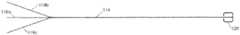
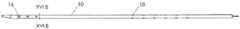
图1A、1B和1C例示了根据示例性实施例、具有可以与导管内的神经刺激电极对齐的窗口的导管的各种视图。1A, 1B, and 1C illustrate various views of a catheter having a window that can be aligned with a nerve stimulation electrode within the catheter, according to an exemplary embodiment.
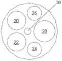
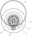
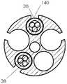
图2是根据示例性实施例的、示出了可以接纳神经刺激电极的腔位置的图1所示的导管的横截面视图。2 is a cross-sectional view of the catheter shown in FIG. 1 illustrating the location of a lumen in which a nerve stimulation electrode may be received, according to an exemplary embodiment.
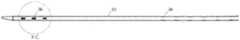
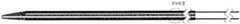
根据示例性实施例,图3A例示了可用于刺激左膈神经的电极组件;图3B例示了图3A中所示的电极的横截面视图;图3C例示了可用于刺激右膈神经的电极组件;并且图3D例示了图3C中所示的电极的横截面视图。Figure 3A illustrates an electrode assembly that can be used to stimulate the left phrenic nerve; Figure 3B illustrates a cross-sectional view of the electrode shown in Figure 3A; Figure 3C illustrates an electrode assembly that can be used to stimulate the right phrenic nerve, according to an exemplary embodiment; And FIG. 3D illustrates a cross-sectional view of the electrode shown in FIG. 3C.
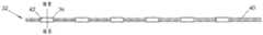
根据示例性实施例,图4A例示了导管;图4B例示了可以被定位在图4A的导管的近端并可用于刺激左膈神经的电极组件;图4C例示了可以被定位在图4A的导管的远端中并可用于刺激右膈神经的的电极组件;并且图4D例示了图4A的导管的横截面视图,其中图4B和4C的电极组件被示为在导管的腔内。FIG. 4A illustrates a catheter; FIG. 4B illustrates an electrode assembly that may be positioned at the proximal end of the catheter of FIG. 4A and may be used to stimulate the left phrenic nerve; FIG. 4C illustrates the catheter that may be positioned in FIG. 4A , according to an exemplary embodiment and Figure 4D illustrates a cross-sectional view of the catheter of Figure 4A with the electrode assembly of Figures 4B and 4C shown within the lumen of the catheter.
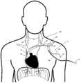
图5例示了人的颈部和上躯干的选定的神经和血管的解剖学结构。Figure 5 illustrates the anatomy of selected nerves and blood vessels of a human neck and upper torso.
图6A例示了根据示例性实施例、由导管和电极对产生的电场线。图6B例示了示例性现有技术的电极的电场线。6A illustrates electric field lines generated by a catheter and electrode pair, according to an exemplary embodiment. FIG. 6B illustrates the electric field lines of an exemplary prior art electrode.
根据示例性实施例,图7A例示了具有缝入导管轴的导线的导管;图7B例示了可插入到图7A的导管中的电极组件;图7C例示了图7A的远侧电极的部分纵向横截面;并且图7D例示了图7A的近侧电极对的横向横截面视图,示出了导管的内腔。FIG. 7A illustrates a catheter with a guide wire sewn into the catheter shaft; FIG. 7B illustrates an electrode assembly insertable into the catheter of FIG. 7A ; FIG. 7C illustrates a partial longitudinal transverse view of the distal electrode of FIG. 7A , according to an exemplary embodiment. and Figure 7D illustrates a transverse cross-sectional view of the proximal electrode pair of Figure 7A, showing the lumen of the catheter.
根据示例性实施例,图8A例示了具有被直接印刷在导管的外部上的电极的导管;图8B例示了图8A的导管的远侧电极的分解图;图8C例示了图8A的导管的近侧电极的分解图;并且图8D例示了图8A的电极对的横向横截面视图。8A illustrates a catheter with electrodes printed directly on the exterior of the catheter; FIG. 8B illustrates an exploded view of a distal electrode of the catheter of FIG. 8A ; FIG. 8C illustrates a proximal portion of the catheter of FIG. 8A, according to an exemplary embodiment. and Figure 8D illustrates a lateral cross-sectional view of the electrode pair of Figure 8A.
根据示例性实施例,图9A例示了导管;图9B例示了可插入到图9A的导管的腔中的近侧和远侧电极组件;图9C例示了图9B中所示的远侧电极组件的分解图;图9D例示了图9B中所示的近侧电极组件的分解图;并且图9E例示了图9A的导管的横向横截面视图。Fig. 9A illustrates a catheter; Fig. 9B illustrates proximal and distal electrode assemblies insertable into the lumen of the catheter of Fig. 9A; Fig. 9C illustrates a Exploded views; Figure 9D illustrates an exploded view of the proximal electrode assembly shown in Figure 9B; and Figure 9E illustrates a lateral cross-sectional view of the catheter of Figure 9A.
根据示例性实施例,图10A和10B例示了具有直接附接到导管的外部上的电极的导管的示图;10C例示了图10A中所示的电极的分解图;图10D例示了单个电极的横向横截面视图;并且图10E例示了图10A的电极对的横向横截面视图。10A and 10B illustrate views of a catheter with electrodes attached directly to the exterior of the catheter; 10C illustrates an exploded view of the electrode shown in FIG. 10A ; and FIG. 10D illustrates a single electrode, according to an exemplary embodiment. lateral cross-sectional view; and FIG. 10E illustrates a lateral cross-sectional view of the electrode pair of FIG. 10A.
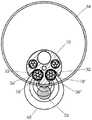
图11A例示了导管;图11B例示了根据第一示例性实施例的通过注射成型被保持在一起的近侧和远侧电极组件;图11C例示了在图11B中所示的远侧电极的分解图;图11D例示了根据第二示例性实施例的通过注射成型被保持在一起的电极组件;图11E例示了图11D中所示的远侧电极的分解图;并且图11F例示了图11A的导管的横向横截面视图,示出了导管腔和腔内的图11B的电极组件。Figure 11A illustrates a catheter; Figure 11B illustrates a proximal and distal electrode assembly held together by injection molding according to a first exemplary embodiment; Figure 11C illustrates an exploded distal electrode shown in Figure 11B 11D illustrates an electrode assembly held together by injection molding according to a second exemplary embodiment; FIG. 11E illustrates an exploded view of the distal electrode shown in FIG. 11D ; and FIG. 11F illustrates the Lateral cross-sectional view of the catheter showing the catheter lumen and the electrode assembly of Figure 1 IB within the lumen.
根据示例性实施例,图12A例示了导管;图12B例示了远侧电极组件的透视图;图12C例示了近侧电极组件的透视图;12D例示了图12B的远侧电极组件的侧视图;图12E例示了图12C的近侧电极组件的侧视图;图12F例示了图12D的远侧电极的横向横截面视图;图12G例示了图12E的近侧电极的横向横截面视图;图12H例示了其中图12B的两个远侧电极组件在导管腔内的图12A的导管的横向横截面视图;图12I例示了其中图12C的两个近侧电极组件在导管腔内的图12A的导管的横向横截面视图;图12J例示了其中ECG缆线通过导管的中心腔的图12H的视图;并且图12K例示了其中ECG缆线通过中心腔的图12I的视图。12A illustrates a catheter; FIG. 12B illustrates a perspective view of a distal electrode assembly; FIG. 12C illustrates a perspective view of a proximal electrode assembly; 12D illustrates a side view of the distal electrode assembly of FIG. 12B; Figure 12E illustrates a side view of the proximal electrode assembly of Figure 12C; Figure 12F illustrates a lateral cross-sectional view of the distal electrode of Figure 12D; Figure 12G illustrates a lateral cross-sectional view of the proximal electrode of Figure 12E; Figure 12H illustrates A transverse cross-sectional view of the catheter of FIG. 12A with the two distal electrode assemblies of FIG. 12B within the catheter lumen; FIG. 12I illustrates the catheter of FIG. 12A with the two proximal electrode assemblies of FIG. 12C within the catheter lumen. Lateral cross-sectional views of the catheter; Figure 12J illustrates the view of Figure 12H with the ECG cable passing through the central lumen of the catheter; and Figure 12K illustrates the view of Figure 12I with the ECG cable passing through the central lumen.
根据示例性实施例,图13A例示了导管;图13B例示了具有弓形电极的远侧电极组件的透视图;图13C例示了具有弓形电极的近侧电极组件的透视图;图13D例示了图13B的远侧电极组件的侧视图;图13E例示了图13C的近侧电极组件的侧视图;图13F例示了图13D的远侧电极的横向横截面视图;图13G例示了图13E的近侧电极的横向横截面视图;图13H例示了其中图13B的两个远侧电极组件在导管腔内的图13A的导管的横向横截面视图;图13I例示了其中图13C的两个近侧电极组件在导管腔内的图13A的导管的横向横截面视图;图13J例示了图13H的视图,具有通过导管的中心腔的ECG缆线;并且图13K例示了图13I的视图,具有通过中心腔的ECG缆线。Figure 13A illustrates a catheter; Figure 13B illustrates a perspective view of a distal electrode assembly with arcuate electrodes; Figure 13C illustrates a perspective view of a proximal electrode assembly with arcuate electrodes; Figure 13D illustrates Figure 13B, according to an exemplary embodiment Figure 13E illustrates a side view of the proximal electrode assembly of Figure 13C; Figure 13F illustrates a lateral cross-sectional view of the distal electrode of Figure 13D; Figure 13G illustrates the proximal electrode of Figure 13E 13H illustrates a transverse cross-sectional view of the catheter of FIG. 13A with the two distal electrode assemblies of FIG. 13B within the catheter lumen; FIG. 13I illustrates the two proximal electrode assemblies of FIG. 13C A transverse cross-sectional view of the catheter of FIG. 13A within the catheter lumen; FIG. 13J illustrates the view of FIG. 13H with the ECG cable passing through the central lumen of the catheter; and FIG. 13K illustrates the view of FIG. 13I with the central lumen passing through the catheter. ECG cable.
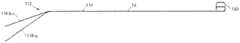
图14例示了根据示例性实施例的单独屏蔽的ECG缆线。14 illustrates an individually shielded ECG cable according to an exemplary embodiment.
图15A、15B和15C例示了根据示例性实施例、用于使远侧导管尖端转向的转向机制的各种视图。15A, 15B, and 15C illustrate various views of a steering mechanism for steering a distal catheter tip, according to an exemplary embodiment.
根据示例性实施例,图16A例示了具有包括强化元件和附着在导管的中央腔内的两根拉线的转向机制的导管;图16B例示了图16A的导管的横向横截面,示出了在中心腔中的转向机制;图16C例示了转向机制的侧视图;图16D例示了图16A的导管的远侧部分的纵向横截面视图,示出了转向机制的分解图;并且图16E例示了在图16D中所示的转向机制的一部分的分解图。Figure 16A illustrates a catheter with a steering mechanism comprising a stiffening element and two puller wires attached within a central lumen of the catheter; Figure 16B illustrates a transverse cross-section of the catheter of Figure 16A, showing a central Steering mechanism in the lumen; Figure 16C illustrates a side view of the steering mechanism; Figure 16D illustrates a longitudinal cross-sectional view of the distal portion of the catheter of Figure 16A, showing an exploded view of the steering mechanism; Exploded view of a portion of the steering mechanism shown in 16D.
图17A和17B示出了根据示例性实施例、包括两个具有激光切割部分以帮助直接弯曲的皮下管的转向机制。17A and 17B illustrate a steering mechanism including two hypodermic tubes with laser cut sections to facilitate direct bending, according to an exemplary embodiment.
根据示例性实施例,图18A例示了具有包括直径腔的转向机制的导管,每个直径腔具有拉线;图18B例示了转向机制的拉线;图18C例示了图18A的导管的横向横截面视图;图18D例示了图18A的导管的远侧部分的纵向横截面视图,示出了转向机制;并且图18E例示了在图18D中示出的转向机制的一部分的分解图。18A illustrates a catheter having a steering mechanism including diameter lumens, each diameter lumen having a puller wire; FIG. 18B illustrates a puller wire of a steering mechanism; FIG. 18C illustrates a transverse cross-sectional view of the catheter of FIG. 18A ; Figure 18D illustrates a longitudinal cross-sectional view of the distal portion of the catheter of Figure 18A showing the steering mechanism; and Figure 18E illustrates an exploded view of a portion of the steering mechanism shown in Figure 18D.
根据示例性实施例,图19A例示了具有包括插入通过皮下管/压缩线圈并附着在中央腔内的单根推/拉线的转向机制的导管;图19B例示了转向机制;图19C例示了图19A的导管的横向横截面视图;图19D例示了图19A的导管的远侧部分的纵向横截面视图,示出了转向机制;并且图19E例示了在图19D中示出的转向机制的一部分的分解图。Figure 19A illustrates a catheter with a steering mechanism comprising a single push/pull wire inserted through a hypodermic tube/compression coil and attached within a central lumen; Figure 19B illustrates a steering mechanism; Figure 19C illustrates Figure 19A, according to an exemplary embodiment Figure 19D illustrates a longitudinal cross-sectional view of the distal portion of the catheter of Figure 19A, showing the steering mechanism; and Figure 19E illustrates an exploded view of a portion of the steering mechanism shown in Figure 19D picture.
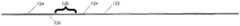
图20A、20B和20C例示了根据示例性实施例、具有不同的窗口对齐的导管。20A, 20B, and 20C illustrate catheters with different window alignments, according to an exemplary embodiment.
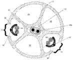
图21例示了根据示例性实施例、人类血管以及左和右膈神经的背视图,其中预成形的导管插入血管内。21 illustrates a dorsal view of a human blood vessel and left and right phrenic nerves with a preformed catheter inserted into the blood vessel, according to an exemplary embodiment.
根据示例性实施例,图22A例示了具有沿其长度的纵向槽的导管;并且图22B例示了图22A的导管的横截面视图。22A illustrates a catheter having longitudinal grooves along its length; and FIG. 22B illustrates a cross-sectional view of the catheter of FIG. 22A, according to an exemplary embodiment.
根据示例性实施例,图23A例示了具有沿其长度的部分的纵向槽的导管;并且图23B例示了图23A的导管的横截面视图。23A illustrates a catheter having longitudinal grooves along portions of its length; and FIG. 23B illustrates a cross-sectional view of the catheter of FIG. 23A, according to an exemplary embodiment.
根据示例性实施例,图24A例示了在图22A-22B或23A-23B的导管内的电极组件,其中套筒被示为覆盖导管的一部分;并且图24B例示了图24A的横截面视图。24A illustrates an electrode assembly within the catheter of FIGS. 22A-22B or 23A-23B, with the sleeve shown covering a portion of the catheter, according to an exemplary embodiment; and FIG. 24B illustrates a cross-sectional view of FIG. 24A.
根据示例性实施例,图25A例示了具有内部导管芯和外部绝缘护套的带状线导管的侧视图;图25B例示了图25A的导管的透视图;并且图25C例示了图25A的导管的横截面视图。25A illustrates a side view of a stripline conduit having an inner conduit core and an outer insulating jacket; FIG. 25B illustrates a perspective view of the conduit of FIG. 25A; and FIG. 25C illustrates a perspective view of the conduit of FIG. 25A, according to an exemplary embodiment. Cross-sectional view.
根据示例性实施例,图26A例示了附接到带状线导管的电极;图26B例示了图26A的导管的近侧电极对的横截面视图,图26C例示了图26A的导管的远侧电极对的横截面视图;图26D例示了图26A的带状线导管,示为附接到导丝腔并处于闭合位置;图26E例示了处于打开位置的图26D的带状线导管;图26F例示了相对于血管壁和目标神经的图26D的带状线导管;图26G例示了处于打开位置的图26A的带状线导管的透视图;并且图26H例示了具有拉线的图26G的带状线导管。Figure 26A illustrates an electrode attached to a stripline catheter; Figure 26B illustrates a cross-sectional view of a proximal electrode pair of the catheter of Figure 26A, and Figure 26C illustrates a distal electrode of the catheter of Figure 26A, according to an exemplary embodiment 26D illustrates the stripline catheter of FIG. 26A, shown attached to the guidewire lumen and in a closed position; FIG. 26E illustrates the stripline catheter of FIG. 26D in an open position; FIG. 26F illustrates Figure 26D illustrates the stripline catheter of Figure 26D relative to the vessel wall and target nerve; Figure 26G illustrates a perspective view of the stripline catheter of Figure 26A in an open position; and Figure 26H illustrates the stripline of Figure 26G with a pull wire catheter.
具体实施方式Detailed ways
贯穿下面的描述,阐述了具体的细节,以便向本领域技术人员提供更透彻的理解。技术的例子的以下描述并非意在详尽的或将系统限定到任何示例实施例的精确形式。相应地,描述和附图应当被认为是说明性而不是限制性的。Throughout the following description, specific details are set forth in order to provide those skilled in the art with a more thorough understanding. The following descriptions of examples of techniques are not intended to be exhaustive or to limit the system to the precise form of any example embodiments. Accordingly, the description and drawings are to be regarded in an illustrative rather than a restrictive sense.
总体概述General overview
一般而言,本公开内容的实施例涉及用于电刺激患者的神经的医疗设备和方法。在一种实施例中,患者的神经可以被刺激,以激活隔膜恢复或控制呼吸。In general, embodiments of the present disclosure relate to medical devices and methods for electrically stimulating nerves in a patient. In one embodiment, the patient's nerves may be stimulated to activate the diaphragm to restore or control breathing.
本文中所描述的医疗设备可以包括多个部件,包括具有细长的管状构件和一个或多个电极组件的导管,向电极组件提供刺激能量的信号发生器,以及感测患者的状况并调节刺激信号的一个或多个传感器。医疗设备还可以包括转向机制。公开了导管的各种实施例,包括开窗的导管、多腔导管以及带状导管。此外,公开了电极组件的各种实施例,其可以单独使用、与其它电极组件组合、以及与构成导管的外部的公开的细长的管状构件中的任意细长的管状构件组合。术语“导管”在本文中可被用来指导管的细长的管状构件或作为整体的组装导管,其可以包括电极组件、转向机制、以及细长的管状构件内或耦接到其的任何其它部件。还描述了多个类型的转向机制。The medical devices described herein may include a number of components, including a catheter having an elongated tubular member and one or more electrode assemblies, a signal generator that provides stimulation energy to the electrode assemblies, and sensing a patient's condition and regulating stimulation signal of one or more sensors. The medical device may also include a steering mechanism. Various embodiments of catheters are disclosed, including fenestrated catheters, multi-lumen catheters, and ribbon catheters. In addition, various embodiments of electrode assemblies are disclosed that can be used alone, in combination with other electrode assemblies, and in combination with any of the disclosed elongated tubular members that make up the exterior of the catheter. The term "catheter" may be used herein to refer to the elongated tubular member of the tube or the assembled catheter as a whole, which may include electrode assemblies, steering mechanisms, and any other within or coupled to the elongated tubular member part. Various types of steering mechanisms are also described.
各种医疗设备部件(例如,导管、电极组件、转向机制等等)的不同实施例可以被以任何逻辑布置组合并在一起使用。此外,任何所述实施例的各个特征或元件可以与其它实施例的各个特征或元件组合或与其结合使用。各种实施例还可以在与本文中具体描述的那些不同的上下文中使用。例如,所公开的电极结构可以与本领域已知的用于各种诊断和/或治疗应用的各种部署系统组合或与其结合使用。Different embodiments of various medical device components (eg, catheters, electrode assemblies, steering mechanisms, etc.) may be combined and used together in any logical arrangement. Furthermore, various features or elements of any described embodiment may be combined or used in combination with various features or elements of other embodiments. The various embodiments may also be used in contexts other than those specifically described herein. For example, the disclosed electrode structures can be combined or used in combination with various deployment systems known in the art for various diagnostic and/or therapeutic applications.
在使用期间,医疗设备(例如,具有一个或多个电极组件的导管)可被插入患者的血管,使得电极组件靠近患者的神经。然后,电极组件可被用于患者的神经的经血管电刺激。所公开的设备可以为在患者体内的快速、暂时部署和从患者容易去除而优化。所公开的设备可被用于,例如,恢复呼吸、治疗诸如废用性肌萎缩和慢性疼痛的状况、或用于涉及神经刺激的任何其它规程。所公开的设备可被用于治疗急性或慢性状况。During use, a medical device (eg, a catheter having one or more electrode assemblies) may be inserted into a patient's blood vessel such that the electrode assemblies are proximate to the patient's nerves. The electrode assembly can then be used for transvascular electrical stimulation of the patient's nerves. The disclosed device may be optimized for rapid, temporary deployment within a patient and easy removal from the patient. The disclosed devices may be used, for example, to restore breathing, to treat conditions such as disuse muscle atrophy and chronic pain, or for any other procedure involving nerve stimulation. The disclosed device can be used to treat acute or chronic conditions.
医疗设备概述:导管和电极组件Medical Device Overview: Catheter and Electrode Assemblies
参照图1-6B,将描述医疗设备以及使用方法的示例性实施例的概述。以后将参照附图来描述各种医疗设备部件的附加或选择性实施例。1-6B, an overview of an exemplary embodiment of a medical device and method of use will be described. Additional or alternative embodiments of various medical device components will be described hereinafter with reference to the drawings.
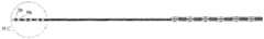
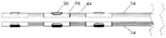
图1A、1B和1C例示了根据示例性实施例的导管10的各种视图。在图1A、1B和1C中,导管10被在围绕通过导管10的纵轴A-A的不同旋转位置中示出。导管10可以包括由挤压的聚氨酯(或任何其它合适的生物相容性材料)制成的细长的管状构件。如可在图1A中看到的,导管10可以包括一行远侧窗口16,其可以在导管10的远端12附近沿纵轴对齐。导管10还可以包括第二行远侧窗口16,其可以部分地见于图1C。在导管10上靠近窗口16的位置14处(在一些情况下,在导管10的近端处),导管10可以类似地包括两行近侧窗口18。这些窗口将在本文被称为“近侧窗口18”,以便区分近侧窗口组18与远侧窗口组16。在其它实施例中,导管10可以包括三行或更多行远侧窗口16或三行或更多行近侧窗口18。近侧窗口18可以具有与远侧窗口16相同或不同的结构特征。导管10在近侧窗口18与远侧窗口16之间的部分可以没有窗口。1A, 1B and 1C illustrate various views of the
在一种实施例中,导管10包括六个远侧窗口16和十二个近侧窗口18。但是,在其它实施例中,导管10可以包括更少或更多的近侧或远侧窗口。例如,在其它实施例中,导管10可以包括两个、四个、八个、十个、十二个或更多个远侧窗口16,和/或两个、四个、六个、八个、十个或多于十二个近侧窗口18。远侧窗口16和近侧窗口18可以成对配置,使得导管10具有偶数个远侧窗口16和偶数个近侧窗口18。但是,窗口16或18的数目也可以是奇数。In one embodiment, the
窗口16、18可以通过导管10的外壁被切割(例如,通过激光、手动研磨(manualskive)、钻、冲头等等),或者窗口可以通过任何其它合适的方法形成,诸如在挤压过程或其它制造过程期间。窗口16、18可以沿纵轴A-A被拉长。它们可以具有矩形、椭圆形、正方形或任何其它形状。窗口16、18可以是被配置为允许电信号从导管10的内部腔行进到导管10的外部的孔。在附加的或选择性实施例中,窗口16、18可以被允许电信号穿过的材料覆盖。如在图中可以看到的,近侧窗口18可以从远侧窗口16旋转偏移。换句话说,在一种实施例中,在近侧通过一行远侧窗口16绘制的直线不穿过一行近侧窗口18。在其它实施例中,一行或多行近侧窗口18可以与远侧窗口16的对应的行对齐。The
导管10的维度可以根据特定患者的解剖学结构定制。但是,在一些实施例中,导管10包括近侧窗口18的部分的长度可以是10cm或更小、在3-5cm之间、或者在1-3cm之间。两个相邻的近侧窗口18(不管窗口是纵向相邻还是在同一行窗口上相邻)之间的距离可以是5cm或更小、3cm或更小、或者可以是大约1cm。导管10包括远侧窗口16的部分的长度可以是6cm或更小、在2-4cm之间、或者在1-2cm之间。两个相邻的远侧窗口16(不管是纵向相邻还是在同一行窗口上相邻)之间的距离可以是5cm或更小、3cm或更小、或者可以是大约1cm。导管在近侧窗口18与远侧窗口16之间可以没有窗口的部分的长度可以是12cm或更小、10cm或更小、或8cm或更小。窗口16、18可以具有6mm或更小、5mm或更小、4mm或更小、3mm或更小、2mm或更小或者1mm或更小的长度。在一种实施例中,窗口可以具有小于通过窗口电暴露的对应电极的长度的长度。应当理解,以上导管的维度仅仅是示例性的,并且导管10可以具有不同于以上范围和特定测量的维度。The dimensions of the
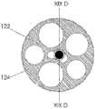
图2例示了沿导管10的平面II-II(参见图1A)的横截面视图。导管10的内部可以包括一个或多个腔。在一种实施例中,导管10可以包括六个腔20、22、24、26、28、30,但是导管10可以包括更少或更多的腔。腔20、22、24和26可以是被用来接纳在下面进一步详细描述的电极组件的电极组件腔。在一种实施例中,近侧窗口18可以创建腔20、22的内部与导管10的外部之间的通路。因此,腔20、22可以接纳与在图1A-1C中所示的近侧窗口18对齐的电极。类似地,远侧窗口16可以创建腔24、26的内部与导管10的外部之间的通路,并且腔24、26可以接纳与在图1A-1C中所示的远侧窗口16对齐的电极。因此,腔20、22可以是近侧电极组件腔,并且腔24、26可以是远侧电极组件腔。如将在下面更详细描述的,放在腔20、22中的近侧电极组件可被用来刺激患者的左膈神经,并且放在腔24、26中的远侧电极组件可被用来刺激患者的右膈神经。腔28可以接纳导丝,并且腔30可以接纳转向机制、其它仪器、缆线,或者可被用来将流体输送到工作现场或从中输送。FIG. 2 illustrates a cross-sectional view along plane II-II of catheter 10 (see FIG. 1A ). The interior of
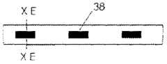
图3A例示了近侧电极组件32的示例性实施例,并且图3B例示了沿图3A的平面IIIB-IIIB的单个电极36的横截面视图。在一种实施例中,近侧电极组件32可以包括六个近侧电极36。类似地,图3C例示了远侧电极组件34的示例性实施例,并且图3D例示了沿图3C的平面IIID-IIID的单个电极38的横截面视图。远侧电极组件34可以包括三个远侧电极38。就电极的数目、电极的结构特征以及组件作为整体的结构特征而言,两个电极组件32和34可以彼此不同。3A illustrates an exemplary embodiment of a
近侧电极组件32可以被保持在导管10的近侧电极组件腔20、22之一当中,并且第二近侧电极组件32可以被保持在导管10的近侧电极组件腔20、22中的另一个当中。类似地,远侧电极组件34可以被保持在导管10的远侧电极组件腔24、26之一当中,并且第二远侧电极组件34可以被保持在导管10的远侧电极组件腔24、26中的另一个当中。导管10的腔内两个近侧电极组件32和两个远侧电极组件34的这种组合可以允许十二个近侧电极36与十二个近侧窗口18对齐并且六个远侧电极38与六个远侧窗口16对齐。The
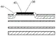
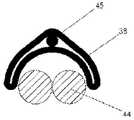
将参照图3A和图3B来更详细地描述近侧电极组件32。各个电导线44可以被盘绕在一起,以形成近侧电极组件32的线缆40。每根导线44可以包括细长的导电构件45并且可以被一层非导电材料46包围。在一种实施例中,导线44可以是缆线,细长的导电构件45可以包括不锈钢或另一导电材料的线股,并且非导电材料46可以是绝缘层。导线44可以向电极36并从其递送电信号或其它信号。The
在一种实施例中,线缆40可以包括七根导线44。关于这七根导线44,其中六根可以在某些位置(例如,在电极36下方,如图3B中所示)单独去绝缘,以便暴露下方的导电构件45。可以薄、柔性且由不锈钢或另一导电材料制成的导电连接器42可以接合(例如,机械地、粘合剂、微焊接等等)到暴露的导电构件45并横向缠绕在线缆40周围。导电连接器42可以提供暴露的导电构件45与电极36之间的接触表面。在一种实施例中,电极36可以是铂-10%铱(或者任何其它合适的可植入电极材料,像不锈钢,铂、氮化钛、涂覆的不锈钢等等)环形电极,其被压接(crimped)(或粘附、微焊接)到线缆40和导电连接器42的外部。在图3B的中心中示出的第七绝缘导线44可以帮助支撑并强化线缆40。第七导线44也可被用来承载其它类型的信号,例如来自传感器的信号或ECG信号。如上所述,总共两个七引线近侧电极组件可以被插入到导管10的腔20、22中。In one embodiment, the
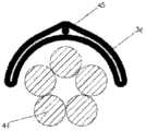
参照图3C和3D,远侧电极组件34的线缆48可以包括三根电导线44,其可以以与关于近侧电极组件32所描述的类似方式构造。三个电极38可以被安装到导电连接器42,导电连接器42连接到对应导线44的暴露的导电构件45。在附加的或选择性实施例中,部分或半圆形电极可代替环形电极36、38被使用。导管10内腔的数目、线缆40、48的数目、每根线缆40、48上相应的电极36、38的数目、以及电极36、38之间的距离,连同其它结构特征一起,可以改变,以适合特定的应用。Referring to FIGS. 3C and 3D , the
在一种实施例中,近侧电极36或远侧电极38当中任一可被用来测量来自患者体内的电信号或其它数据。换句话说,除了或者替代发射或接收电能以产生用于神经刺激的局部电流,电极还可以充当从患者接收电或其它类型信息的传感器。In one embodiment, either the
图4A-4D例示了多个电极组件32、34可以如何在导管10的腔内。导管10被在图4A中绘出,两个近侧电极组件32在图4B中绘出,并且两个远侧电极组件34在图4C中绘出。两个近侧电极组件32可以被放在导管10的腔20、22中,使得电极36与近侧窗口18对齐。类似地,两个远侧电极组件34可以被放在导管10的腔24、26中,使得电极38与远侧窗口16(图4A中未示出)对齐。一旦对齐,电极组件32、34就可以被固定在其各自的导管腔内(例如,利用粘合剂或通过任何其它结构或方法)。图4D例示了沿图4A的平面IVD-IVD截取的导管10的横截面,其示出了在导管10的腔20、22、24、26中具有两个近侧电极组件32和两个远侧电极组件34的导管。4A-4D illustrate how the plurality of
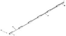
参照图5,医疗设备50可以包括具有两个近侧电极组件32和两个远侧电极组件34的导管10。电极组件32、34可以在导管10的细长的管状构件中,使得电极36通过近侧窗口18暴露并且电极38通过远侧窗口16暴露。由电导线44形成的线缆40、48可以通过导管10的近端离开并且可以附接到连接器52、54(例如,通过焊料、压接、PCB等等)。Referring to FIG. 5 , a
为了组装医疗设备50,可以包括导线44和电极36、38的电极组件32、34可以通过在导管10的近端或远端的腔开口被引入到一个或多个腔中。例如,导线44可以被插入到导管10的近端并且穿透或拉过一个或多个腔,直到电极36、38被定位在导管10的更远侧部分中的预定位置。在将电极组件32、34插入之前或之后,导管壁的部分可以被除去,以创建窗口18、16。窗口18、16可以暴露电极,从而允许电极36、38与血管腔之间的导电通路,医疗设备50可被放在血管腔中。To assemble
仍然参照图5,在示例性使用方法中,医疗设备50可被用于在人或其它哺乳动物(例如,猪、黑猩猩)的颈部和/或胸部中神经的经血管刺激。图5例示了在人的颈部和胸部中选定的神经和血管的解剖学结构并且,尤其是,左膈神经(PhN)56、右膈神经58、迷走神经(VN)(未示出)、外部或内部颈静脉(JV)60、头臂静脉(BCV)62、上腔静脉(SVC)64和左锁骨下静脉(LSV)66的相对位置。Still referring to Figure 5, in an exemplary method of use, a
医疗设备50可被用来通过将导管10经皮插入患者的中央静脉来有节奏地激活隔膜,其中导管10具有一个或多个电极组件32、34。导管10的经皮插入可以通过Seldinger技术实现,其中导丝通过皮下注射针插入静脉。然后,导管的远侧尖端越过导丝并推入到静脉中。导管的形状和机械特性可被设计为促使导管10在右和左膈神经附近区域轻轻环抱(hug)静脉壁,如图5中所示。The
在图5的实施例中,医疗设备50可被插入左锁骨下静脉66并推入到上腔静脉64中。在未示出的另一配置中,医疗设备50可被插入左颈静脉并被推入到上腔静脉64中。导管10可以微创方式被插入并且可被暂时放入患者中,并因此可从其除去。在一种实施例中,窗口18被定向成使得,当导管被插入左锁骨下静脉66时,六对窗口18被向后朝左膈神经56指向并且三对远侧窗口16被横向朝右膈神经58指向。In the embodiment of FIG. 5 , the
在一种实施例中,电极组件34可以包括被布置并定向成最有效地刺激平行于导管10延伸的神经(例如,图5中的右膈神经58)的电极38,并且电极组件32可以包括被布置并定向成最有效地刺激与导管10成横向角或直角延伸的神经(例如,图5中的左膈神经56)的电极36。在附加的或选择性实施例中,电极组件34可以包括被布置并定向成最有效地刺激与导管10成横向角或直角延伸的神经的电极38,并且电极组件32可以包括被布置并定向成最有效地刺激平行于导管10延伸的神经的电极。在上述实施例中,电极组件34的电极38已被放在沿导管10比电极组件32的电极36更远的位置。但是,在其它实施例中,电极组件32可以被布置在导管10内,使得其电极36比电极组件34的电极38更远。在这种选择性实施例中,导管10的窗口16、18可被配置为适应电极组件32、34的选择性放置。In one embodiment,
一旦导管被完全插入患者,各对双极电极组合就可以被测试,以定位所关心的神经并确定哪些电极最有效地刺激所关心的神经。例如,在一种实施例中,可以进行测试,以定位右膈神经58并确定(远侧电极组38中)哪对电极38最有效地刺激右膈神经58。类似地,可以进行测试,以定位左膈神经56并确定(近侧电极组36中)哪些对电极36最有效地刺激左膈神经56。作为非限制性例子,测试可以涉及使用信号发生器来系统地向选定的电极发送电脉冲。通过观察病人的状况或通过使用传感器,可以识别理想的电极对。Once the catheter is fully inserted into the patient, each pair of bipolar electrode combinations can be tested to locate the nerve of interest and determine which electrodes stimulate the nerve of interest most effectively. For example, in one embodiment, a test may be performed to locate the right
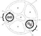
图6A例示了沿图4A中所示的平面VIA-VIA的导管10的横截面视图并且将被参照来描述为了刺激神经的一对电极的选择性激活。图6A的电极可以是位于沿导管10的任意位置的任意电极对,并且神经56可以是相对于导管10平行、横向或以任意其它定向定位的任意神经。但是,为了便于描述,近侧电极36和左膈神经56联系图6A被参照,虽然左膈神经56在图5中被示为横穿导管10。虽然在图6A中未示出,但是一对远侧电极38也可以被选择性地激活,以刺激右膈神经58。Figure 6A illustrates a cross-sectional view of the
在“选择性激活”期间,电势可在一对选定的双极电极之间创建,诸如在第一电极36'与第二电极36″之间创建。第一电极36'可与第一窗口18'对齐,并且第二电极36″可与第二窗口18″对齐。第一和第二电极36'、36″与第一和第二窗口18'、18″的布置可以在第一和第二窗口18'、18″的附近创建电场68。第一和第二电极36'、36″可被选择为有效地把神经作为目标,诸如在图6A中所示的左膈神经56或者在电极36'、36″附近的另一神经。窗口18'、18″和作为结果的电场68可以因此朝左膈神经56或其它目标神经定向。During "selective activation", an electrical potential may be created between a selected pair of bipolar electrodes, such as between the first electrode 36' and the
在神经刺激期间,电流从电极36'、36″当中的一个流到电极36'、36″当中的另一个,流经窗口16'、16″并流经血液和周围组织。因此,具有窗口16'、16″的导管10充当约束和聚焦电场68的绝缘屏障,而不是允许电场68在所有方向上径向向外扩张。聚焦的电场允许在较低能级下的目标神经刺激并且避免刺激不需要的神经或其它结构。在一些实施例中,刺激电流可以在10-6000nC(nanocoulomb(纳库仑))之间或50-500nC之间。During nerve stimulation, current flows from one of the
图6B例示了可被用来刺激神经78的示例性现有技术神经刺激设备70。现有技术设备70可以包括导线72和电极74。设备70可被插入到血管76中,并且电场80可以在设备70周围创建。如在图6B中可以看到的,电场80可以在设备70的圆周周围被创建。虽然它可以以神经78为目标,但是电场并不限于特定的位置并且因此也可以以患者体内的其它解剖结构为目标。因此,一般而言,导管10的窗口16、18可以允许使用更低更安全的电流来激活膈神经56、58并防止附近的结构(诸如其它神经、肌肉或心脏)的过度刺激或不需要的激活。FIG. 6B illustrates an exemplary prior art
电极组件实施例Electrode Assembly Example
图7A-13K例示了可与本文中描述的任意导管一起使用的电极和电极组件的附加或选择性实施例。下面的实施例可以是先前所描述的电极组件和电极的变体。因此,未提及的特征可以不变或者是上述实施例的逻辑修改。为了便于参照,每种实施例的近侧电极36、近侧电极组件32、远侧电极38和远侧电极组件34将利用与以上所使用的相同标号提及,但是这些部件的一些特征可以在以下实施例中被修改。7A-13K illustrate additional or alternative embodiments of electrodes and electrode assemblies that may be used with any of the catheters described herein. The following embodiments may be variations of the electrode assemblies and electrodes previously described. Therefore, unmentioned features may be unchanged or logical modifications of the above-described embodiments. For ease of reference, the
裸/缝合线bare/suture
参照图7A-7D,非导电材料46的层可以从导线44的部分被除去,以暴露底层的导电构件45。图7A例示了导管10,并且图7B例示了近侧电极组件32。导线44的暴露的导电构件45(直的或者为了增加的表面积而是盘绕的)可以位于导管10的窗口16或18中并且,在一些实施例中,可以径向延伸出窗口16、18。在另一实施例中,如图7C中所示,导电构件45可以通过导管外壁中的孔穿出导管10的腔,在近侧-远侧方向上行进,并且然后通过导管10的外壁中的另一个孔返回。形成电极36、38的导电构件45的部分可以是导线44的远端。绝缘导线44可以附加地或代替地被缝入导管10中,将暴露的导电构件45留在导管10的外部并且将剩余的绝缘导线44留在导管腔内部。图7D例示了通过包括暴露的导电构件45的一对近侧电极36的导管10的横截面。7A-7D, a layer of
在一些实施例中,导电构件(诸如联系图10A-10E描述的电极)可以被固定到(例如,利用粘合剂、热熔融等等)导管10的外部并且(例如,机械地,微焊接地)与暴露的导电构件45电接触。相对于仅包括暴露的导电构件45的电极,将这种导电构件固定到暴露的导电构件45可以增加电极的某些电特性,诸如导电性和表面积。导电构件材料的例子包括铂、铂铱、金、不锈钢、氮化钛、MP35N、钯等等。In some embodiments, conductive members (such as the electrodes described in connection with FIGS. 10A-10E ) may be secured (eg, with an adhesive, heat fused, etc.) to the exterior of the
印刷电极printed electrodes
图8A例示了具有被直接印刷在导管10的外部上的电极和导线的导管。图8B例示了导管10的远侧电极38的分解图,图8C例示了导管10的近侧电极36的分解图,并且图8D例示了沿图8C的平面VIIID-VIIID截取的近侧电极对36的横向横截面视图。电极36、38可以由导电油墨(诸如悬浮在聚合物中的银薄片或碳薄片)形成。这些导电油墨可以被直接沉积并附着到导管10上并且除了暴露的电极36、38之外被用外聚氨酯或其它柔性绝缘膜密封。为了诸如以下一个或多个目的:增强电特性,诸如导电性和表面积;提供耐腐蚀性;以及减少形成可能有毒的氧化银的潜力,暴露的电极36、38也可以被涂覆(例如,用氮化钛)。如可在图8C中看到的,远侧电极38的导电墨迹可以沿导管10在近侧行进超过近侧电极36。FIG. 8A illustrates a catheter with electrodes and wires printed directly on the exterior of the
印刷电极的使用可以在最大化可用导管腔空间的同时减小设计的整体复杂性,而不太明显地改变导管轮廓或灵活性。但是,在一些实施例中,导管的轮廓可以由于通过使用印刷在导管的外部上的电极所节省的空间而减小。在附加的或选择性实施例中,一个或多个导管腔可被用于流体输送、血液采样、或中央静脉压力监测。在另一个附加的或选择性实施例中,若干导管腔,诸如腔20、22、24、26,可被消除,因为没有如联系其它实施例所描述的导管组件。因此,在一种实施例中,导管10可以仅包括腔28和腔30。如果具有印刷电极的导管10包括少于图2中所示的六个腔,例如,其横截面区域可以减小,则更少腔当中一个或多个可以做得更大,以容纳更大的工具或其它对象,或者一个或多个更小的腔可以被添加以容纳工具或其它对象。The use of printed electrodes can reduce the overall complexity of the design while maximizing the available catheter lumen space without significantly altering the catheter profile or flexibility. However, in some embodiments, the profile of the catheter may be reduced due to the space saved by using electrodes printed on the exterior of the catheter. In additional or alternative embodiments, one or more catheter lumens may be used for fluid delivery, blood sampling, or central venous pressure monitoring. In another additional or alternative embodiment, several catheter lumens, such as
电极支撑导管electrode support catheter
图9A-9E例示了由可被放在导管10的腔中的导管94、96支撑的电极36、38。在这种实施例中,近侧电极36可以由电极导管94接合,并且远侧电极38可以由电极导管96接合。导管94、96可以是包括非导电材料的细长的管状构件。电极36、38可以压接到导管94、96上并且可以通过电极导管94、96的壁被电连接到导线44的导电构件45。导管94、96可以具有小于其各自的导管10的腔的横截面区域的横截面区域,使得导管94、96可被插入导管10的腔当中。当导管94、96被插入导管10时,电极36、38可以与导管10的窗口18、16对齐并且固定在适当位置,类似于其它实施例。虽然未在图9E中示出,但是导线44可以通过电极导管94、96在近侧-远侧方向上行进。9A-9E illustrate
在附加的或选择性实施例中,具有单个电极36或38或一对双极电极的一个或多个导管可以在过程期间(即,当导管10在患者的血管系统中时)被插入导管10的腔并前进到各个窗口18、16,直到找到最佳位置。通过这样做,可以使用更少的材料,这可以降低医疗设备50的生产成本。In additional or alternative embodiments, one or more catheters with a
外部电极external electrode
图10A-10E例示了在导管10的外部上的电极36、38。在图10A-10E的实施例中,电极36、38可以被连接(微焊接等等)到导线44并且可以固定(例如,压接、附着等等)到导管10的外部。导线44可以通过导管10的壁插入(例如,通过窗口16、18)并插入导管10中的腔。10A-10E illustrate
在其它实施例中,一个或多个环形电极可以被固定到导管10的外部。为了便于一个或多个神经的定向定位,绝缘涂层可以被应用,以覆盖电极的一部分。In other embodiments, one or more ring electrodes may be secured to the exterior of
注射成型injection molding
图11A-11F例示了其中电极组件32、34的制造过程可以包括注射成型的实施例。为了获得在图11B和11C中所示的电极构造,电极36、38可以通过注射成型被单独附接到导线44,其中电极36、38与导电构件45电接触。成型过程可以形成围绕每根导线44的覆盖物98。覆盖物98可以包括非导电材料,诸如塑料。电极36、38可以是平的、半圆形的、或任何其它合适的形状。类似地,覆盖物98可以形成围绕导线44的任何形状,诸如图11F中所示的形状。11A-11F illustrate an embodiment in which the manufacturing process of the
在图11D和11E中所示的另一实施例中,电极36、38和导线44的束可以被放入在导线44的束周围注射材料(诸如塑料)的注射成型夹具中,以便将电极锚定在适当位置,从而形成覆盖物98,但在一种实施例中,留下电极38的至少一部分暴露。在一些实施例中,电极可以被一薄层聚合物覆盖,该薄层聚合物可在随后的步骤中被除去。在图11C的实施例中,覆盖物98可以被放在电极的纵向附近并且可能仅围绕单根导线,并且因此可以被称为“部分”。在图11E的实施例中,覆盖物98可以覆盖底层导线44的较大纵向部分并且可以围绕多根导线,并且因此可以被称为“完整”。一旦每个电极38被锚定到导线44,电极组件32、34就可被插入导管10的腔并与窗口18、16对齐。In another embodiment shown in Figures 11D and 11E, the bundles of
由管状构件支撑的电极Electrodes supported by tubular members
图12A-12K例示了电极组件32、34的又一实施例。在这种实施例中,管状构件100可以支撑导线44的远端102并且保持远端102与电极36、38相邻。12A-12K illustrate yet another embodiment of
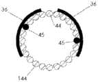
图12A例示了导管10;图12B例示了远侧电极组件34的透视图;图12C例示了近侧电极组件32的透视图;图12D例示了图12B的远侧电极组件34的侧视图;图12E例示了图12C的近侧电极组件32的侧视图;图12F例示了图12D的远侧电极38的横向横截面视图;图12G例示了图12E的近侧电极36的横向横截面视图;图12H例示了其中图12B的两个远侧电极组件34在导管腔内的图12A的导管的横向横截面视图;图12I例示了其中图12C的两个近侧电极组件32在导管腔内的图12A的导管10的横向横截面视图;图12J例示了其中ECG线通过导管10的中心腔的图12H的视图;并且图12K例示了其中ECG线通过导管10的中心腔的图12I的视图。Figure 12A illustrates
图12B-12G分别例示了近侧和远侧电极组件32、34的近侧和远侧电极36、38。如可在图中看到的,电极组件32、34包括导线44,类似于其它实施例。如在图12F和12G中最清楚示出的,导线44的远侧部分102可以包括暴露的导电构件45并且可以通过焊接或任何其它方法附接到管状构件100的外部和电极36、38的内部。管状构件100的可以是1-6mm的长度、可以是2-4mm的长度、并且在一种实施例中可以是大约3mm的长度,但是管状构件100可以是任何其它合适的长度。管状构件100可以是不锈钢皮下管。(在图12B-12E中,管状构件100没有示出并且将全部或大部分被电极36、38覆盖。导线44的远侧部分102被在图12D和12E中标记,以示出它们的大致位置,尽管它们在电极36、38的下方。)如可以在图12F和12G中看到的,导线44的远侧部分102可以使电极36、38径向向外突出。12B-12G illustrate the proximal and
每根导线44可以在近侧行进通过比该导线的远端102附接到的电极更近定位的任何电极38、36。例如,参照图12B,附接到远侧电极组件34的最远侧电极38的导线44可以在近侧行进通过其它两个电极38并通过所有六个近侧电极36。参照图12C,附接到最远侧电极36的导线44可以在近侧行进通过其它五个电极36当中每一个。Each lead 44 may be advanced proximally through any
在一种实施例中,远侧电极组件34可以包括三根导线44-每个电极38一根。类似地,近侧电极组件32可以包括六根导线44-每个电极36一根。当每个电极组件32、34的导线44接合在一起时,导线可以被盘绕,以形成线缆48、40。在更远侧的位置,线缆48(由来自远侧电极组件34的导线44形成)可以包括一根或两根导线。在更近侧的位置,诸如靠近最近侧电极38,线缆48可以包括三根导线44。类似地,在更远侧的位置,线缆40(由来自近侧电极组件32的导线形成)可以包括一根、两根、三根、四根或五根导线。在更近侧的位置,诸如靠近最近侧电极36,线缆40可以包括六根导线44。In one embodiment, the
图12H和12I例示了电极组件34、32在导管10的腔内的横截面视图。虽然在图12H和12I中所例示的导管10的腔可以与图2中所示不同地被成形,但是导管10仍然可以包括被配置为接纳近侧电极组件32的腔20、22,被配置为接纳远侧电极组件34的腔24、26,被配置为接纳导丝的腔28,以及被配置为接纳转向机制或其它结构的腔30。如可在图12H中看到的,远侧电极38可以与远侧窗口16对齐。图12I例示了与近侧窗口18对齐的近侧电极36。来自远侧电极组件34的导线44可以在图12I的横截面视图中看到,因为导线44可以在近侧行进通过腔24、26。12H and 12I illustrate cross-sectional views of
除了图12J和12K例示了在腔30中的两个心电图(ECG)导电构件104之外,图12J和12K类似于图12H和12I中所示的视图。ECG导电构件104可以被耦接到位于导管10的远端的一个或多个ECG电极106(参见图12A和图14),用于感测患者的ECG信号。Figures 12J and 12K are similar to the views shown in Figures 12H and 12I, except Figures 12J and 12K illustrate two electrocardiogram (ECG)
图12A-12K的实施例的一个益处是每个电极36、38可以相对于其它电极36、38可移动。虽然电极36、38由导线44连接,但是导线44通常是柔性的。因此,当在制造医疗设备50的过程中在导管10中放置电极组件32、34时,这种实施例允许每个电极36、38被至少部分地独立于其它电极定位在其各自的窗口18、16中。与其中电极36、38通过导管或其它刚性结构被固定到其它电极的实施例相反,电极的独立定位可以允许定位误差被最小化。One benefit of the embodiment of FIGS. 12A-12K is that each
弓形电极bow electrode
图13A-13K例示了类似于在图12A-12K中所示实施例的实施例。与图12A-12K的实施例类似的功能在这里将不再重复。图13A-13K的实施例与图12A-12K的实施例之间的主要区别是图13A-13K的电极36、38当中每一个可以形成弓形形状,其用来保持并接触导线44的远端102(包括暴露的导电构件45)。图13A-13K的近侧和远侧组件32、34可以包括或可以不包括管状构件100。Figures 13A-13K illustrate an embodiment similar to the embodiment shown in Figures 12A-12K. Similar functionality to the embodiment of Figures 12A-12K will not be repeated here. The primary difference between the embodiment of FIGS. 13A-13K and the embodiment of FIGS. 12A-12K is that each of the
如在图13F和13G中所示,电极36、38当中每一个可以是C形并且可以具有外壁108和内壁110。电极的外壁108和内壁110可以在导线44的远端102夹住暴露的导电构件45。As shown in FIGS. 13F and 13G , each of
心电图电极ECG electrodes
图14例示了两个ECG电极106及其关联的部件。就像对于本申请中的所有其它特征,ECG电极106可以本文中描述的任何其它实施例一起使用。ECG电极106可以位于导管10的远端(见图12A)。在一种实施例中,导管10可以包括两个ECG电极106,但是在一些实施例中,导管10可以包括一个电极106或多于两个电极106。可以是绝缘的导电构件104可以将每个电极106连接到位于患者体外的ECG系统。ECG导电构件104可以被编织或缠绕在一起并且可以被非导电层105(也在图12J和12K中示出)包围。Figure 14 illustrates two
电极106可以监测患者的心率。在医疗设备50的使用过程中,心率监测对于提醒医师患者的心率变化会是有益的。患者的心率变化可以由医疗设备50刺激某些神经或者由患者心脏的无意刺激引起。也可以依靠心率监测来实现神经的稳定补充(recruitment)。例如,当患者的心脏跳动时,导管10可以移动,从而引起神经刺激的波动。如果患者的心率是已知的,则在一对双极神经刺激电极之间创建的电势可以被实时地调节,以向神经递送恒定的电荷。
转向机制steering mechanism
各种转向机制可以包括在医疗设备50中,以帮助控制血管内导管窗16、18的定位,并因此控制电极38、36的定位。转向机制可位于导管10的中心腔30中或者在导管10的其它腔中。将至少一些电极36、38定位为紧邻每个目标神经会是有益的,因为让电极位于靠近神经可以减少通过血液分流的电流量并因此可以减少激活神经所需的电流。Various steering mechanisms may be included in the
多个因素可以帮助将近侧窗口18定位在血管内的期望位置中。例如,典型的锁骨下静脉渗透角度以及导管10的形状和弹性可以组合,以沿锁骨下静脉的后壁定位近侧窗口18,非常靠近左膈神经,其通常背侧下降至左锁骨下静脉。A number of factors may assist in positioning the
为了确保导管10的远侧部分,包括窗口16和它们关联的电极38,相对于右膈神经被定位在期望的位置,医疗设备50可以包括强化元件和转向机制。在一种实施例中,强化元件和转向机制可以帮助靠着上腔静脉的侧壁定位远侧电极组38,靠近右膈神经。To ensure that the distal portion of the
转动构件转向机制Turning member steering mechanism
参照图15A-15C,转向机制112可以包括单个预成形的细长构件114,诸如引线或管(即,不锈钢、镍钛诺、皮下管等等),以使导管10转向。细长构件114可以包括手柄120、耦接到手柄120的近侧部分116、以及相对于近侧部分116弯曲的远侧部分118。当近侧部分116经由手柄120转动时,远侧部分118可以对应地变成各种位置并且可以用来定位导管10的远端。15A-15C, the
图15A-15C例示了处于三个不同位置的细长构件114:由远侧部分118a指示的第一位置、由远侧部分118b指示的第二位置、以及由远侧部分118c指示的第三位置。图15A例示了处于三个不同位置的转向机制112的正视图,图15B例示了处于三个不同位置的转向机制112的顶视图,并且图15C例示了当转向机制112处于三个不同位置时从转向机制112的远端到转向机制112的近端的视图。15A-15C illustrate
细长构件114可以足够刚硬,以确保包括远侧电极38的导管10的远侧部分,靠着血管壁放置。细长构件114也可以足够刚硬,以从近侧手柄120向远侧部分118传送转向扭矩。The
控制构件转向机制Control member steering mechanism
参照图16A-16E,转向机制112的另一实施例可以包括一个或多个控制构件122。在一种实施例中,控制构件122可以被拉或推,以弯曲或偏转导管10的一部分。控制构件122可以被一个或多个管状构件124(诸如皮下管或压缩线圈)包围或者可以相对于其纵向滑动。管状构件124可以是柔性的。这种实施例的转向机制112还可以包括强化元件126,诸如管或杆,其可被附接(例如,通过焊接、粘合剂等等)到管状构件124。Referring to FIGS. 16A-16E , another embodiment of the
图16A-16E的实施例可以允许导管10的双向转向。在转向机制112的近端,手柄(未示出)可以促进控制构件122相对于它们对应的管状构件124的拉或推。如图16C中所示,转向组件112的远端可以包括管状构件124之间的间隙128。间隙128可以促进导管10的远端的弯曲。一旦组装好,转向机制112就可以附着在导管10的中央腔30或另一腔内。The embodiment of FIGS. 16A-16E may allow bidirectional steering of the
参照图17A和17B,在附加的或选择性实施例中,管状构件124可以包括变窄的部分130。变窄的部分130可以代替间隙128或者可以结合间隙128使用,以提供期望的柔性。变窄的部分130可以使用激光或通过任意其它方法形成。Referring to FIGS. 17A and 17B , in additional or alternative embodiments, the
参照图18A-18E,在转向机制112的又一实施例中,控制构件122可以位于导管10内的单独的腔132、134中。类似于图16A-16E的实施例,控制构件122可以被可以是皮下管或压缩线圈的一个或多个管状构件124包围。在一种实施例中,每个管状构件124不围绕其各自的控制构件122的远端部分。因此,控制构件122的远端部分可被固定到其对应的腔132、134的远端。每个管状构件124的远端部分也可以在离控制构件122的固定部分更近的位置处固定到其对应的腔132、134。沿腔纵向延伸的间隙可以留在控制构件122的固定部分与其对应的管状构件124的固定部分之间,使得当控制构件122相对于其管状构件124被拉或推时,导管10的偏转在有间隙的空间内发生。Referring to FIGS. 18A-18E , in yet another embodiment of the
在又一实施例中,参照图19A-19E,转向机制112可以包括单个控制构件122。控制构件122可以被管状构件124包围并且可以相对于管状构件124被推或拉,以偏转导管10的远端。控制构件122的远端部分可以固定在导管10的腔30或另一腔的远端内,并且管状构件124可以固定到腔30内更近侧的位置。再次,间隙可以在控制构件122的固定部分与管状构件124的固定部分之间形成,以控制导管10的偏转位置。在一种实施例中,控制构件122可以被拉,以在一个方向上偏转导管尖端,并且被推,以在另一相反的方向上偏转导管尖端。In yet another embodiment, referring to FIGS. 19A-19E , the
在一些实施例中,上述任何转向机制可以包括气囊,其可被充气,以辅助靠着上腔静脉侧壁推动导管10的远端部分以及远侧电极38。气囊可被附接到导管与对应于远侧电极38的窗口相反的一侧。一旦气囊充气,电极38就可以朝上腔静脉的壁被推动。In some embodiments, any of the steering mechanisms described above may include a balloon, which may be inflated to assist in pushing the distal portion of
导管实施例catheter embodiment
导管窗口布置Catheter Window Arrangement
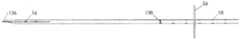
参照图20A-20C,导管10的窗口16、18可以具有各种替代构造。例如,代替如图1中所示那样对齐,窗口16可以从其它窗口16偏移,并且窗口18可以相对于导管10的外表面上的近侧-远侧线136或相对于导管10的圆周周围的圆周线138从其它窗口18偏移。例如,如果更近侧的窗口16不位于通过最远侧窗口16的中心绘制的相同近侧-远侧线136上,则窗口16可以彼此偏移。图20B和20C的每个窗口18可以相对于通过窗口18的中心绘制的圆周线138从其它窗口18偏移。导管10的实施例包括具有偏移和不偏移窗口的任何构造的窗口16、18。如前面所述,窗口16的集合或窗口16的行可以相对于近侧-远侧线136从窗口18的集合或窗口18的行偏移。20A-20C, the
除了电极与神经的接近性,电极相对于神经的构造,如由窗口16、18确定的,可以减少刺激神经轴突所需的电流的量。当电极和电流流动的方向平行于或沿着神经时,神经轴突可能需要较低的激活电流,从而产生具有足够量值的纵向跨膜去极化,以引发动作电势。神经历程的方向不是完全已知的并且从一个体到另一个可以有所不同。In addition to the proximity of the electrodes to the nerve, the configuration of the electrodes relative to the nerve, as determined by the
提供多个不同的可能电极构造允许将电极组的选择用于个体中的神经刺激。使用近侧电极36作为例子,电极对可以布置在直线上(例如,像图20A那样沿着圆周线138)、交错(例如,图20B)或者沿着导管10的圆周成一定角度(例如,图20C),以确保神经可被有效地刺激。参照图20A,圆周线138可以穿过两个电极的中心(或越过),或圆周线138可以穿过两个电极的其它部分(或越过)(例如,该对电极可以稍微偏移)。参照图20B,交错的电极对可以被布置成使得纵向相邻的电极之间(诸如电极18a和18b之间)的纵向距离(沿平行于导管10的纵轴的近侧-远侧线)近似地等于其它对纵向相邻的电极(诸如18b和18c)之间的纵向距离。参照图20C,成角度的电极对可以布置成使得穿过电极对的中心的平面不相对于导管10的纵轴形成直角。因此,图20B的交错电极实施例是图20C的成角度电极实施例的子集,并且其中圆周线138穿过电极对的非中心部分或越过的图20A的实施例也可以被认为包括成角度的电极对。电极构造可以沿导管10变化,以解释在不同患者中发现的解剖学结构差异。尽管存在这些差异,但选择适当的电极对可以提供有效的神经刺激。Providing a number of different possible electrode configurations allows for selection of electrode sets for neural stimulation in an individual. Using the
预成形的导管preformed catheter
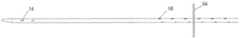
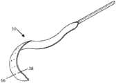
图21例示了根据本文公开的任何实施例、具有预成形的导管10的医疗设备50,其中导管10具有电极36、38。预成形的导管10可以具有弓形、盘绕、S形、U形或任何其它预成形的部分。即使在右膈神经比正常更靠前或靠后前进(course)的个体当中,预成形的导管10也可以帮助确保电极36、38与血管壁紧密接触并且因此更接近膈神经或其它神经。21 illustrates a
导管10的预成形可以,例如,通过强化插入在导管腔内的元件实现,或者在制造过程中预成形。预成形的导管10可以是柔性的但是可以有一些硬度并且可以趋于返回到其预成形的构造。当在更硬的导丝上插入时,为了便于插入,导管10可以被拉直。当导丝被取出时,导管10可以返回其预成形形式。Pre-forming of the
具有细长的开口的导管catheter with elongated opening
参照图22A-24B,在附加的或选择性实施例中,导管10可以包括沿其外部的细长的开口140。细长的开口140可以将导管10的外部连接到内部腔并且可以被称为狭缝或通道。如图22A-22B中所示,细长的开口140可以沿着导管10的全长延伸。附加地或选择性地,如图23A-23B中所示,细长的开口140可以沿着导管10的长度的部分延伸。如图24A和24B中所示,细长的开口140可以附加地或选择性地被套筒142覆盖。22A-24B, in additional or alternative embodiments, the
由于腔的长度和它们的小直径,在医疗设备50的组装过程中将电极组件32、34穿线通过导管10的腔会给出挑战。在图22A-24B的实施例中,电极组件32、34可以通过细长的开口140被插入导管10的一个或多个腔。从腔外面径向的位置,而不是从腔的近端和远端,访问导管10的腔的能力可以在制造过程中简化医疗设备50的电导线44和其它部件的安装。Threading the
细长的开口140可以在形成导管10的初始挤压或模制过程中被创建,或者可以在以后的步骤中被创建。用于第一挤压或模制的合适聚合物的一些非限制性例子是:低和高密度热塑性聚氨酯,诸如聚酯、聚醚、和基于聚碳酸酯的变种;基于聚碳酸酯的聚氨酯;以及聚酰胺(尼龙)和聚酰胺嵌段共聚物(PEBA)。The
如图24A和24B中所示,在电极组件32、34被安装在导管10的腔中之后,外套筒142可以被拧套在导管10之上,以将引线组件固定在腔内。外套筒142可以是聚合物管状套筒并且可以通过挤压而形成。外套筒142的内直径可以大到足以在导管10的外侧上滑动,但可以小到足以在导管10上滑动之后将电极组件32、34保持在导管10的腔内。外套筒142可以沿导管10的期望长度在近侧-远侧方向上延伸。As shown in Figures 24A and 24B, after the
外套筒142可以由薄的热塑性材料(诸如但不限于聚酰胺、聚醚嵌段酰胺、聚氨酯、硅橡胶、尼龙、聚乙烯、氟化烃聚合物等等)形成。适于在套筒中使用的的聚合物材料的例子在商标PEBAXTM和PELLETHANETM下可商购。The outer sleeve 142 may be formed from a thin thermoplastic material such as, but not limited to, polyamide, polyether block amide, polyurethane, silicone rubber, nylon, polyethylene, fluorinated hydrocarbon polymers, and the like. Examples of polymeric materials suitable for use in sleeves are commercially available under the trademarks PEBAX™ and PELLETHANE™ .
外套筒142可以热接合或以其它方式通过多种方法中任何一种机械地附接到导管10。在一种这样的方法中,可通过挤压形成的管状构件可以被放在导管10和外套筒142之上并围绕其。管状构件可以是可收缩的,以靠着外套筒142压缩。例如,管状构件可包括热缩管。热缩管可以依赖于期望的特性由一层或多层形成。作为例子,来自Parker TexLoc(FortWorth,TX)的热缩管具有两层,用于电绝缘。Texflour含氟聚合物双收缩热缩管具有PTFE热收缩的外层和FEP管的内层。当使用双收缩管时,当PTFE收缩时,导管10可以被FEP管封装,从而熔化FEP并创建防水保护性覆盖物,这对于包括RF和电刺激设备的各种应用是期望的。The outer sleeve 142 may be thermally bonded or otherwise mechanically attached to the
然后,热能被应用到热缩管,以在外套筒142和导管10周围压缩热缩管。热缩管的收缩在外套筒142上提供径向向内指向的压缩力。由热缩管施加的压缩力帮助将外套筒142固定到导管10。Thermal energy is then applied to the heat shrink tubing to compress the heat shrink tubing around the outer sleeve 142 and the
与此同时,或者在后面的步骤中,热能(例如,RF加热、电磁感应加热等等)可以被应用到包括热缩管、外套筒142和导管10的组件。热能可以足以提高组件的温度,以便引起外套筒142到导管10的接合。由热缩管生成的压缩力和将材料加热到高于其各自熔化温度的热能的组合将用来把外套筒142和导管10接合在一起。热能通常没有高到足以创建热缩管与聚合物套筒之间的接合,也没有高到足以损坏导管组件的完整性。At the same time, or in a later step, thermal energy (eg, RF heating, electromagnetic induction heating, etc.) may be applied to the assembly including the heat shrink tubing, outer sleeve 142 and
然后,热缩管可以从包括导管10(其被接纳在外套筒142内部)的组件去除。狭缝、缺口、穿孔或其它薄弱区域可被用来辅助热缩管从组件的去除。在一些情况下,收缩管可以由诸如EPTFE的生物相容性材料构造并且可以留在导管组件上。The heat shrink tubing can then be removed from the assembly including the conduit 10 (which is received inside the outer sleeve 142 ). Slits, notches, perforations, or other areas of weakness may be used to assist in the removal of heat shrink tubing from the assembly. In some cases, the shrink tube can be constructed of a biocompatible material such as EPTFE and can be left on the catheter assembly.
在根据本文所公开的任何实施例的导管10的腔中,可能期望插入支撑结构,诸如聚四氟乙烯(例如,特氟龙)涂覆的心轴,其可以提供内部支撑来维持导管10的结构并且贯穿整个制造过程保持纵向腔的通畅。可以稍后通过腔中的远侧或近侧开口拉支撑结构而将其去除。在一些情况下,在去除之前支撑结构可以被拉伸并拉长,由此减小其横截面区域。In the lumen of the
具有不同材料、厚度或材料特性(例如,硬度计)的一个或多个外套筒142可以在沿导管10的长度的各个位置处被使用以更改在沿成品导管的长度的特定位置的各种物理特性(例如,硬度、可扭转性、摩擦等等)。例如,柔性套筒142可以在导管10的远侧部分被利用,以允许导管10的尖端更容易沿着导丝跟踪。更刚硬的套筒142可以在导管10的近侧部分被使用,以允许在抓握导管10的远端时更大的可推动性或可扭转性。相邻的套筒142可以在最终的形成过程中对接焊接或以其它方式端到端耦接。搭接接头或楔面接头可以可选地用于形成相邻的套筒142之间更平滑的过渡。One or more outer sleeves 142 having different materials, thicknesses, or material properties (eg, durometers) can be used at various locations along the length of the
其它元件或者结构可以使用上述组装方法结合到导管10构造中。作为一个例子,为了帮助向导管10的远端提供期望的形状或轮廓,在沿第一挤压的期望位置,成形元件可以被插入到细长的开口140中的一个,或插入到封闭的腔中。成形元件可以是可成形的或预成形的,以赋予导管10期望的构造(例如,期望的曲率)。成形元件可以被预成形或形成为使导管10在具有期望角度关系的平面中弯曲,以诸如像帮助定位医疗设备50的电极36、38。Other elements or structures may be incorporated into the
成形元件可以是弹性柔性的。在一些实施例中,成形元件可以包括预定长度的例如镍钛诺引线、带子、弹簧等等。在一些实施例中,成形元件可以包括依赖温度的形状记忆材料,诸如形状记忆合金。在一些实施例中,成形元件可以被构造为在导管10进入患者的身体之后呈现期望的形状。例如,体温可能导致形状记忆成形元件改变成期望形状的构造,或者外部能量源(例如,电流)可以被应用,以通过热或其它机制引起成形元件的形状变化。在一些实施例中,成形元件在致动时变得更加弯曲。The shaping element may be elastically flexible. In some embodiments, the shaping element may comprise a predetermined length of, for example, Nitinol leads, straps, springs, and the like. In some embodiments, the shaped element may comprise a temperature-dependent shape memory material, such as a shape memory alloy. In some embodiments, the shaping element may be configured to assume a desired shape after the
选择性导线实施例Alternative lead embodiment
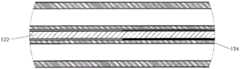
参照图25A-26H,在附加的或选择性实施例中,电极导线44之一或全部可以被嵌在柔性带状线缆144中。带状线缆144可以包括沿其长度被连接以形成单个平面结构的多个绝缘导线44。平面结构可以是柔性的,以形成其它形状。类似于本文描述的其它导线44,带状线缆144的导线44可以包括被一层非导电材料46(诸如绝缘体)包围的细长的导电构件45。Referring to FIGS. 25A-26H , in additional or alternative embodiments, one or all of the electrode leads 44 may be embedded in the
在图25A-25C的实施例中,带状线缆144可以作为柔性圆筒被闭合(例如,围绕心轴形成并且近似的带子边缘沿长度利用粘合剂固定)。这种设计可以允许任何导线44在沿导管长度的点被去绝缘并附接到电极36、38,诸如像柔性箔电极或根据本文描述的任何实施例形成的电极。带状线缆实施例的两个近侧电极36可以在图25C的横截面中看到并且将在下面更详细地描述。导管10的外部细长的管状构件可以利用先前描述的热缩法围绕带状线缆144形成,以形成平滑的电绝缘壁。类似于其它实施例,个别电极36、38可以通过在导管10中形成的窗口18、16暴露。In the embodiment of Figures 25A-25C, the
图25A-25C的实施例的优点是整个导管10横截面的较大部分可用于导丝和/或流体腔(一个或多个)。如图25C中所示,带状线缆144可以由支撑导管146支撑,支撑导管146可以包括联系其它实施例描述的腔或者可以包括在图25C中所示的导丝腔28和递送腔148。图25A-25C的实施例的另一优点是它的简单性和易于制造。An advantage of the embodiment of Figures 25A-25C is that a larger portion of the
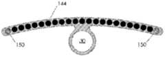
图26A-26H更详细地例示了带状线缆144的使用。参照图26B,近侧电极36可以接触带状线缆144中的导线44。参照图26C,远侧电极38可以接触带状线缆144中的不同导线44。带状线缆144可以暂时利用弱粘合剂(诸如在与血液接触时溶解的粘合剂,诸如蔗糖)保持为圆筒形式。如图26D和26E中所示,导丝腔30或其它腔可以永久附接到(例如,使用强生物相容性粘合剂)带状线缆144。带状线缆144和任何支撑导管146可以由薄的电绝缘覆盖物包裹,以形成导管10(例如,通过将组件滑动到套筒142中以及使用先前描述的热缩法等)。密封可以直接在带状线缆144密封之上被打开(例如,使用刀或激光),以将带状线缆144从图26D中所示的闭合姿态转变成图26E中所示的打开姿态。粘合剂可被用来将带状线缆144从图26E中所示的姿态转变成图26D中所示的姿态。就像在其它实施例中,窗口16、18可以在导管10的外部覆盖物中形成,以便在其期望的位置露出电极36、38。26A-26H illustrate the use of
具有带状线缆144的导管10可以以其封闭构造被引入主体身体的血管中(见图26D)。一旦在血管内,粘合剂就会在几分钟内溶解并且带状线缆144可以自由地部署成几乎平坦的构造,由于带状线缆144的自然弹性,它可以处于其优选状态。可选地,两个控制构件150(诸如镍钛诺或其它弹簧金属丝)或拉线,可以沿着带状线缆144的边缘被嵌入,并且它们的自然弹性和/或操作可以有助于图26E中所示的期望的打开构造。
参照图26F,带状线缆144和/或控制构件150的自然弹性可以有助于以使得电极接近在目标神经(诸如右膈神经58)附近的血管壁的方式朝血管壁推动带状线缆144。利用这种设计,通过窗口18、16暴露的导管电极36、38当中一个或多个有可能非常接近目标神经并且可以利用非常低的电流或电荷递送得到神经的高度选择性补充。此外,这种设计提供了电极36、38与血管中血液的有效绝缘,从而最小化到不需要的区域的电流扩散并且最大化目标神经的选择性补偿。26F, the natural elasticity of the
图26G是具有预期要部署在血管内的带状线缆144的导管10的等距视图。在这种实施例中,导管10的近侧部分在带状线缆144利用将不溶解在血液中的永久性粘合剂附着的区域中可以具有近似圆形、管状的横截面。与此相反,导管10的远侧部分在图26G中示为已经打开成打开的带状线缆构造,其中带子边缘的附接是暂时的并且一旦在血管腔内粘合剂就溶解。在图26G中还看到,具有带状线缆144的导管的远侧部分可以自然地采用曲折(或“螺旋”)构造,其维度是由沿带状线缆边缘嵌入的控制构件150的特性确定的。一种构造可以是大约20mm直径并且大约30mm长度的曲折部分。这种构造可以确保远侧导线中的一些非常靠近,例如,在上腔静脉64(在图24G中未示出,但在图21中示出)的外侧前进的目标右膈神经58。26G is an isometric view of the
图26H例示了可被用来限制具有带状线缆144的导管10的远侧盘绕部分的总长度的控制构件152。控制构件152可以附接到导管10的远端附近的一个点并且可以自由地贯穿导管的近侧部分内的腔,从而横过到患者体外,在那里,拉线的近端可以由医师来控制。通过拉动控制构件152,具有带状线缆144的导管10可被控制成在SVC内最大程度地打开,从而确保带子表面完全靠在血管壁上部署。FIG. 26H illustrates a control member 152 that may be used to limit the overall length of the distal coiled portion of the
具有气压计的医疗设备Medical equipment with barometer
医疗设备50可以包括气压校正,这允许设备50在不同的高度操作,因为接收隔膜的电刺激膈神经起搏的患者可能需要呼吸恒定氧供应,但空气的密度随着高度下降。自然校正是让患者更深和/或更快速地呼吸,以进行补偿。医疗设备50或导管10可以包括测量大气压以补偿高度变化的计量器(例如,气压计)。高海拔性能对于军事、运送受伤人员的任何其它机构(滑雪场,登山者)以及更普遍地需要起搏并需要在飞行器中旅行的任何患者尤为重要。The
配有电子芯片的医疗设备Medical devices with electronic chips
医疗设备50或导管10可以配备有存储关于导管10和/或其使用的信息的电子芯片。芯片可以,例如,在导管10的轮毂中提供。在一种实施例中,当导管10耦接到控制器时,控制器可以读取芯片并且只有当芯片具有正确的加密和/或作出正确的响应等等时才向电极36、38发送信号。芯片可以存储信息,诸如导管的序列号;尺寸(长度和/或直径);批次;批号;生产日期;电极布置;电极互连信息(用于通过导管中的导体连接到电极的连接器的引脚)等等当中一个或多个。控制器可以接受算法更新,这仅适用于参照存储在芯片中的信息确定的某些序列号或导管类型。The
其它选择性实施例和术语的解释Explanation of other optional embodiments and terms
如前面所提到的,本文所公开的任意实施例的任意部件和特征可以与本文公开的任意其它部件和特征以任意逻辑组合被组合并使用。但是,为了示例,所描述的示例实施例可以按其变化的一些方式包括:As previously mentioned, any components and features of any embodiments disclosed herein may be combined and used in any logical combination with any other components and features disclosed herein. However, for the sake of illustration, some of the ways in which the described example embodiments may be varied include:
●不同数量的电极;●Different numbers of electrodes;
●不同的电极构造;●Different electrode structures;
●不同的电极固定(压接、粘合剂、微焊接等等);● different electrode fixation (crimping, adhesive, micro welding, etc.);
●不同的电极形状(圆形、椭圆形、环形、矩形等等);●Different electrode shapes (circular, oval, annular, rectangular, etc.);
●不同的电极材料;●Different electrode materials;
●不同的电极表面积;●Different electrode surface areas;
●不同的电极间距;●Different electrode spacing;
●不同数量或形状的腔;● different numbers or shapes of cavities;
●不同的窗口形状/维度;● different window shapes/dimensions;
●不同的导管轮廓(例如,+/-9Fr);different catheter profiles (eg, +/- 9Fr);
●不同的导管长度;和/或different catheter lengths; and/or
●不同的转向机制。●Different steering mechanisms.
除非上下文清楚地另外要求,否则贯穿本描述和权利要求:Unless the context clearly requires otherwise, throughout this description and claims:
●“包括”、“包含”等应当以包容的意义,而不是排他或详尽的意义,来解释;即,在“包括但不限于”的意义上;● "including", "including", etc. should be construed in an inclusive sense, rather than an exclusive or exhaustive sense; that is, in the sense of "including but not limited to";
●“连接”、“耦接”或其任何变体意味着两个或更多个元件之间的任何连接或耦接,无论是直接的还是间接的;元件之间的的耦接或连接可以是物理的、逻辑的、或者是其组合;● "connected", "coupled" or any variation thereof means any connection or coupling, whether direct or indirect, between two or more elements; a coupling or connection between elements may be is physical, logical, or a combination thereof;
●当用来描述本说明书时,“在本文”、“以上”、“以下”以及类似含义的词语,应当作为整体指本说明书,而不是指本说明书的任何特定部分;When used to describe this specification, "herein", "above", "below" and words of similar import shall refer to this specification as a whole and not to any particular part of this specification;
●在参考两个或更多个项的列表时,“或”覆盖词语的所有以下解释:列表中的任何项、列表中的所有项,以及列表中项的任意组合;及- when referring to a list of two or more items, "or" covers all of the following interpretations of the word: any item in a list, all items in a list, and any combination of items in a list; and
●单数形式“一”、“一个”和“该”也包括任何适当复数形式的含义。- The singular forms "a", "an" and "the" also include any appropriate plural meanings.
在本说明书及任意随附权利要求(当存在时)中使用的指示方向的词语,诸如“垂直”、“横向”、“水平”、“向上”、“向下”、“向前”、“向后”、“向内”、“向外”、“左”、“右”、“前”、“后”、“顶部”、“底部”、“下面”、“之上”、“之下”等等依赖于所描述和例示的装置的具体定向。本文所描述的主题可以采取各种选择性定向。相应地,这些方向术语没有严格限定并且不应当狭义地解释。Orientational words such as "vertical", "lateral", "horizontal", "upward", "downward", "forward", " Backward, Inward, Outward, Left, Right, Front, Back, Top, Bottom, Below, Above, Below ", etc., are dependent on the specific orientation of the apparatus described and illustrated. The subject matter described herein can take various alternative orientations. Accordingly, these directional terms are not strictly limited and should not be interpreted narrowly.
为了例示的目的,本文已经描述了系统、方法和装置的具体例子。这些仅仅是例子。本文所提供的技术可以应用到除上述示例系统之外的其它系统。许多改变、修改、添加、省略和置换在本发明的实践中是可能的。本发明包括对本领域技术人员将显而易见的关于所描述的实施例的变体,包括通过以下获得的变体:利用等价特征、元件和/或动作代替特征、元件和/或动作;混合和匹配来自不同实施例的特征、元件和/或动作;将来自本文所述实施例的特征、元件和/或动作与其它技术的特征、元件和/或动作组合;和/或省略组合来自所述实施例的特征,元件和/或动作。Specific examples of systems, methods, and apparatus have been described herein for purposes of illustration. These are just examples. The techniques provided herein may be applied to other systems than the example systems described above. Many changes, modifications, additions, omissions and substitutions are possible in the practice of the present invention. The present invention includes variations on the described embodiments that will be apparent to those skilled in the art, including variations obtained by substituting equivalent features, elements and/or acts for features, elements and/or acts; mixing and matching features, elements, and/or actions from different embodiments; combine features, elements, and/or actions from embodiments described herein with features, elements, and/or actions from other techniques; and/or omit combining features, elements, and/or actions from the described implementations Examples of features, elements and/or actions.
因此,以下所附的权利要求和其后引入的权利要求意在被解释为包括所有此类可被合理推断的修改、置换、添加、省略和子组合。权利要求的范围不应当由在例子中阐述的优选实施例限制,而是应当被给予与作为整体的本说明书一致的最广泛的解释。Accordingly, the following appended claims and the claims hereafter introduced are intended to be construed to include all such modifications, permutations, additions, omissions and sub-combinations as can be reasonably inferred. The scope of the claims should not be limited by the preferred embodiments set forth in the examples, but should be accorded the broadest interpretation consistent with this specification as a whole.
Claims (17)
Priority Applications (1)
| Application Number | Priority Date | Filing Date | Title |
|---|---|---|---|
| CN201911341447.4ACN110975145B (en) | 2013-11-22 | 2014-11-21 | Apparatus and method for assisting breathing by transvascular neural stimulation |
Applications Claiming Priority (3)
| Application Number | Priority Date | Filing Date | Title |
|---|---|---|---|
| US201361907993P | 2013-11-22 | 2013-11-22 | |
| US61/907,993 | 2013-11-22 | ||
| PCT/IB2014/002937WO2015075548A1 (en) | 2013-11-22 | 2014-11-21 | Apparatus and methods for assisted breathing by transvascular nerve stimulation |
Related Child Applications (1)
| Application Number | Title | Priority Date | Filing Date |
|---|---|---|---|
| CN201911341447.4ADivisionCN110975145B (en) | 2013-11-22 | 2014-11-21 | Apparatus and method for assisting breathing by transvascular neural stimulation |
Publications (2)
| Publication Number | Publication Date |
|---|---|
| CN105873630A CN105873630A (en) | 2016-08-17 |
| CN105873630Btrue CN105873630B (en) | 2020-01-03 |
Family
ID=53179034
Family Applications (2)
| Application Number | Title | Priority Date | Filing Date |
|---|---|---|---|
| CN201480071819.5AActiveCN105873630B (en) | 2013-11-22 | 2014-11-21 | Device and method for assisted respiration by transvascular nerve stimulation |
| CN201911341447.4AActiveCN110975145B (en) | 2013-11-22 | 2014-11-21 | Apparatus and method for assisting breathing by transvascular neural stimulation |
Family Applications After (1)
| Application Number | Title | Priority Date | Filing Date |
|---|---|---|---|
| CN201911341447.4AActiveCN110975145B (en) | 2013-11-22 | 2014-11-21 | Apparatus and method for assisting breathing by transvascular neural stimulation |
Country Status (7)
| Country | Link |
|---|---|
| US (8) | US9242088B2 (en) |
| EP (2) | EP3760276B1 (en) |
| JP (3) | JP6456382B2 (en) |
| CN (2) | CN105873630B (en) |
| AU (3) | AU2014351473B2 (en) |
| CA (1) | CA2930809A1 (en) |
| WO (1) | WO2015075548A1 (en) |
Families Citing this family (68)
| Publication number | Priority date | Publication date | Assignee | Title |
|---|---|---|---|---|
| CA2676119C (en) | 2007-01-29 | 2021-01-19 | Simon Fraser University | Transvascular nerve stimulation apparatus and methods |
| IN2014MN01970A (en) | 2012-03-05 | 2015-07-03 | Univ Fraser Simon | |
| EP2863987B1 (en) | 2012-06-21 | 2023-08-02 | Lungpacer Medical Inc. | Transvascular diaphragm pacing systems |
| CN105873630B (en)* | 2013-11-22 | 2020-01-03 | 隆佩瑟尔医疗公司 | Device and method for assisted respiration by transvascular nerve stimulation |
| AU2015208640B2 (en) | 2014-01-21 | 2020-02-20 | Lungpacer Medical Inc. | Systems and related methods for optimization of multi-electrode nerve pacing |
| WO2015196164A2 (en) | 2014-06-21 | 2015-12-23 | Accelemed, Llc | Method and apparatus for neuromodulation treatments of pain and other conditions |
| US12070601B2 (en) | 2014-03-28 | 2024-08-27 | Pinnacle Bionics. Inc. | Stimulation system for exercising diaphragm and method of operation thereof |
| CH709684A1 (en)* | 2014-05-22 | 2015-11-30 | Medmix Systems Ag | Laparoscopic spray applicator and adapter. |
| US20180001107A1 (en) | 2016-07-01 | 2018-01-04 | Btl Holdings Limited | Aesthetic method of biological structure treatment by magnetic field |
| US12295646B2 (en) | 2015-10-05 | 2025-05-13 | Autonomix Medical, Inc. | Smart torquer and methods of using the same |
| US10874830B2 (en)* | 2015-10-05 | 2020-12-29 | Autonomix Medical, Inc. | Smart torquer and methods of using the same |
| US9682235B1 (en) | 2015-12-14 | 2017-06-20 | Stimdia Medical, Inc. | Electrical stimulation for preservation and restoration of diaphragm function |
| US10363090B2 (en)* | 2016-01-05 | 2019-07-30 | Biosense Webster (Israel) Ltd. | Catheter with flow diverter and force sensor |
| WO2017165410A1 (en) | 2016-03-21 | 2017-09-28 | Nalu Medical, Inc. | Devices and methods for positioning external devices in relation to implanted devices |
| EP3439545A4 (en)* | 2016-04-01 | 2019-11-27 | Medical Inc. Kobara | MODULATED EPICARDIC DERIVATION AND PLACEMENT SYSTEM AND METHOD |
| US11247039B2 (en) | 2016-05-03 | 2022-02-15 | Btl Healthcare Technologies A.S. | Device including RF source of energy and vacuum system |
| US11534619B2 (en) | 2016-05-10 | 2022-12-27 | Btl Medical Solutions A.S. | Aesthetic method of biological structure treatment by magnetic field |
| US10583287B2 (en) | 2016-05-23 | 2020-03-10 | Btl Medical Technologies S.R.O. | Systems and methods for tissue treatment |
| WO2017210672A1 (en)* | 2016-06-03 | 2017-12-07 | The Cleveland Clinic Foundation | Systems and methods for monitoring a depth of neuromuscular blockade |
| US10556122B1 (en) | 2016-07-01 | 2020-02-11 | Btl Medical Technologies S.R.O. | Aesthetic method of biological structure treatment by magnetic field |
| US10207103B2 (en)* | 2016-07-05 | 2019-02-19 | Pacesetter, Inc. | Implantable thin film devices |
| EP3484577B1 (en) | 2016-07-18 | 2025-06-18 | Nalu Medical, Inc. | Systems for treating pelvic disorders and pain conditions |
| WO2018035000A1 (en) | 2016-08-13 | 2018-02-22 | Ecom Medical, Inc. | Medical devices with layered conductive elements and methods for manufacturing the same |
| US11141219B1 (en) | 2016-08-16 | 2021-10-12 | BTL Healthcare Technologies, a.s. | Self-operating belt |
| WO2018126062A1 (en) | 2016-12-30 | 2018-07-05 | Nalu Medical, Inc. | Stimulation apparatus |
| WO2018156953A1 (en) | 2017-02-24 | 2018-08-30 | Nalu Medical, Inc. | Apparatus with sequentially implanted stimulators |
| US11006854B2 (en)* | 2017-02-24 | 2021-05-18 | Teleflex Medical Incorporated | Intravascular sensing devices having flexible tip structure |
| AU2018238185A1 (en)* | 2017-03-22 | 2019-08-08 | Cathrx Ltd | Catheter lead and method of manufacture thereof |
| AU2018265016B2 (en) | 2017-05-09 | 2023-01-05 | Nalu Medical, Inc. | Stimulation apparatus |
| US10293164B2 (en)* | 2017-05-26 | 2019-05-21 | Lungpacer Medical Inc. | Apparatus and methods for assisted breathing by transvascular nerve stimulation |
| CN111163834A (en) | 2017-06-30 | 2020-05-15 | 隆佩瑟尔医疗公司 | Device for preventing, reducing and/or treating cognitive impairment |
| US11207517B2 (en) | 2017-07-06 | 2021-12-28 | Stimdia Medical, Inc. | Percutaneous electrical phrenic nerve stimulation system |
| US10195429B1 (en) | 2017-08-02 | 2019-02-05 | Lungpacer Medical Inc. | Systems and methods for intravascular catheter positioning and/or nerve stimulation |
| US10940308B2 (en) | 2017-08-04 | 2021-03-09 | Lungpacer Medical Inc. | Systems and methods for trans-esophageal sympathetic ganglion recruitment |
| US20190175908A1 (en) | 2017-12-11 | 2019-06-13 | Lungpacer Medical Inc. | Systems and methods for strengthening a respiratory muscle |
| US20190255292A1 (en)* | 2018-02-16 | 2019-08-22 | Oscor Inc. | Deflectable sheath with inflatable balloon |
| US10912937B2 (en)* | 2018-04-09 | 2021-02-09 | Tufts Medical Center, Inc. | Methods and devices for guided subdural electrode array placement |
| AU2019222842A1 (en) | 2018-09-10 | 2020-03-26 | Northern Development AS | Percutaneous Lead |
| EP4548964A1 (en) | 2018-11-08 | 2025-05-07 | Lungpacer Medical Inc. | Stimulation systems and related user interfaces |
| KR102137740B1 (en) | 2018-11-15 | 2020-07-24 | (주) 타우피엔유메디칼 | Pacemaker lead for cerclage pacing |
| US20200281522A1 (en)* | 2019-03-06 | 2020-09-10 | Medtronic Xomed, LLC | System and method for improved obstructive sleep apnea diagnostic for implantable devices |
| USD918383S1 (en)* | 2019-04-05 | 2021-05-04 | Tau-Pnu Medical Co., Ltd. | Catheter |
| US12156689B2 (en) | 2019-04-11 | 2024-12-03 | Btl Medical Solutions A.S. | Methods and devices for aesthetic treatment of biological structures by radiofrequency and magnetic energy |
| ES2926904T3 (en) | 2019-04-11 | 2022-10-31 | Btl Medical Solutions A S | Device for the aesthetic treatment of biological structures using radiofrequency and magnetic energy |
| US11691019B2 (en)* | 2019-04-15 | 2023-07-04 | Pacesetter, Inc. | Quadripolar header connector support for pre-molded header of implantable pulse generator |
| WO2020232333A1 (en) | 2019-05-16 | 2020-11-19 | Lungpacer Medical Inc. | Systems and methods for sensing and stimulation |
| WO2020252037A1 (en) | 2019-06-12 | 2020-12-17 | Lungpacer Medical Inc. | Circuitry for medical stimulation systems |
| US11324954B2 (en) | 2019-06-28 | 2022-05-10 | Covidien Lp | Achieving smooth breathing by modified bilateral phrenic nerve pacing |
| ES2804080B2 (en)* | 2019-08-02 | 2021-08-05 | Miralles Raimundo Vicente | Clamping system for electrical stimulation generator |
| US12186010B2 (en) | 2019-09-26 | 2025-01-07 | Biosense Webster (Israel) Ltd. | Wiring for multi-electrode catheter |
| WO2021224678A1 (en) | 2020-05-04 | 2021-11-11 | Btl Medical Technologies S.R.O. | Device and method for unattended treatment of a patient |
| US11878167B2 (en) | 2020-05-04 | 2024-01-23 | Btl Healthcare Technologies A.S. | Device and method for unattended treatment of a patient |
| TWI751624B (en)* | 2020-07-24 | 2022-01-01 | 瑟鎂科技股份有限公司 | Sutureless vascular connector |
| US20220111200A1 (en)* | 2020-10-12 | 2022-04-14 | Synerfuse, Inc. | Lead template and method of use at a spinal treatment site |
| CN112842287B (en)* | 2021-01-05 | 2022-05-17 | 清华大学 | Device and method for measuring vascular sclerosis parameters |
| CN113368391B (en)* | 2021-07-08 | 2022-07-22 | 杭州神络医疗科技有限公司 | Nerve stimulation electrode and stimulation device |
| US11877761B2 (en) | 2021-08-05 | 2024-01-23 | Nextern Innovation, Llc | Systems, devices and methods for monitoring voltage and current and controlling voltage of voltage pulse generators |
| US12089861B2 (en) | 2021-08-05 | 2024-09-17 | Nextern Innovation, Llc | Intravascular lithotripsy system and device |
| US11801066B2 (en) | 2021-08-05 | 2023-10-31 | Nextern Innovation, Llc | Systems, devices and methods for selection of arc location within a lithoplasty balloon spark gap |
| US11957369B2 (en) | 2021-08-05 | 2024-04-16 | Nextern Innovation, Llc | Intravascular lithotripsy systems and methods |
| US11896248B2 (en) | 2021-08-05 | 2024-02-13 | Nextern Innovation, Llc | Systems, devices and methods for generating subsonic pressure waves in intravascular lithotripsy |
| US12296161B2 (en) | 2021-09-14 | 2025-05-13 | Hemisphere Medical LLC | Subdural sound with a receiving channel |
| EP4415812A1 (en) | 2021-10-13 | 2024-08-21 | BTL Medical Solutions a.s. | Devices for aesthetic treatment of biological structures by radiofrequency and magnetic energy |
| US11896816B2 (en) | 2021-11-03 | 2024-02-13 | Btl Healthcare Technologies A.S. | Device and method for unattended treatment of a patient |
| CN114927913B (en)* | 2022-06-08 | 2025-08-19 | 北京领创医谷科技发展有限责任公司 | Multi-conductive elastic electrode and connection method thereof |
| JP2024022956A (en)* | 2022-08-08 | 2024-02-21 | 日本ライフライン株式会社 | Insertable parts and electrodes |
| WO2025030085A1 (en)* | 2023-08-03 | 2025-02-06 | Synchron Australia Pty Limited | Systems and devices for recording neural activity or stimulating neural tissue and methods of operation thereof |
| WO2025171173A1 (en) | 2024-02-08 | 2025-08-14 | IV-X Medical, LLC | Intravascular lithotripsy system |
Citations (5)
| Publication number | Priority date | Publication date | Assignee | Title |
|---|---|---|---|---|
| US7322954B2 (en)* | 2003-04-25 | 2008-01-29 | Ad-Tech Medical Instrument Corp. | Catheter assembly for intracranial treatment using dual lumens |
| US20100036451A1 (en)* | 2007-01-29 | 2010-02-11 | Simon Fraser University | Transvascular nerve stimulation apparatus and methods |
| US20110106101A1 (en)* | 2009-10-30 | 2011-05-05 | Advanced Bionics, Llc | Steerable Stylet |
| CN102821676A (en)* | 2010-01-29 | 2012-12-12 | C·R·巴德股份有限公司 | Sacrificial catheter |
| US20130116743A1 (en)* | 2011-11-04 | 2013-05-09 | Medtronic, Inc. | Method and apparatus for therapies of the cardiovascular and cardiorenal system |
Family Cites Families (485)
| Publication number | Priority date | Publication date | Assignee | Title |
|---|---|---|---|---|
| US1693734A (en) | 1923-06-29 | 1928-12-04 | Mcintosh Electrical Corp | Switching means for effecting electrotherapeutic treatment |
| US2532788A (en) | 1948-01-03 | 1950-12-05 | Stanley J Sarnoff | Artificial respiration by electronic stimulation |
| US2664880A (en) | 1951-11-23 | 1954-01-05 | Jr Nathaniel B Wales | Electric stimulator for artificial respiration |
| US3348548A (en) | 1965-04-26 | 1967-10-24 | William M Chardack | Implantable electrode with stiffening stylet |
| US3470876A (en) | 1966-09-28 | 1969-10-07 | John Barchilon | Dirigible catheter |
| US3835864A (en) | 1970-09-21 | 1974-09-17 | Rasor Ass Inc | Intra-cardiac stimulator |
| US3769984A (en) | 1971-03-11 | 1973-11-06 | Sherwood Medical Ind Inc | Pacing catheter with frictional fit lead attachment |
| US3817241A (en) | 1972-02-16 | 1974-06-18 | Henry And Carol Grausz | Disposable central venous catheter and method of use |
| US3938502A (en) | 1972-02-22 | 1976-02-17 | Nicolaas Bom | Apparatus with a catheter for examining hollow organs or bodies with the ultrasonic waves |
| US3804098A (en) | 1972-04-17 | 1974-04-16 | Medronic Inc | Body implantable lead |
| US3896373A (en) | 1972-11-30 | 1975-07-22 | Stein Paul D | Method and apparatus for determining cross-sectional area of a blood conduit and volumetric flow therethrough |
| US3847157A (en) | 1973-06-18 | 1974-11-12 | J Caillouette | Medico-surgical tube |
| US3851641A (en) | 1973-11-29 | 1974-12-03 | J Toole | Method and apparatus for determining internal impedance of animal body part |
| US3983881A (en) | 1975-05-21 | 1976-10-05 | Telectronics Pty. Limited | Muscle stimulator |
| US4054881A (en) | 1976-04-26 | 1977-10-18 | The Austin Company | Remote object position locater |
| US4114601A (en) | 1976-08-09 | 1978-09-19 | Micro Tec Instrumentation, Inc. | Medical and surgical implement detection system |
| USRE31873F1 (en) | 1976-09-08 | 1988-11-15 | Venous catheter device | |
| US4072146A (en) | 1976-09-08 | 1978-02-07 | Howes Randolph M | Venous catheter device |
| US4173228A (en) | 1977-05-16 | 1979-11-06 | Applied Medical Devices | Catheter locating device |
| US4249539A (en) | 1979-02-09 | 1981-02-10 | Technicare Corporation | Ultrasound needle tip localization system |
| US4317078A (en) | 1979-10-15 | 1982-02-23 | Ohio State University Research Foundation | Remote position and orientation detection employing magnetic flux linkage |
| US4380237A (en) | 1979-12-03 | 1983-04-19 | Massachusetts General Hospital | Apparatus for making cardiac output conductivity measurements |
| US4630611A (en) | 1981-02-02 | 1986-12-23 | Medtronic, Inc. | Orthogonally-sensing lead |
| US4643201A (en) | 1981-02-02 | 1987-02-17 | Medtronic, Inc. | Single-pass A-V lead |
| US4416289A (en) | 1981-05-07 | 1983-11-22 | Mccormick Laboratories, Inc. | Circuits for determining very accurately the position of a device inside biological tissue |
| US4445501A (en) | 1981-05-07 | 1984-05-01 | Mccormick Laboratories, Inc. | Circuits for determining very accurately the position of a device inside biological tissue |
| US4431005A (en) | 1981-05-07 | 1984-02-14 | Mccormick Laboratories, Inc. | Method of and apparatus for determining very accurately the position of a device inside biological tissue |
| US4431006A (en) | 1982-01-07 | 1984-02-14 | Technicare Corporation | Passive ultrasound needle probe locator |
| US4407294A (en) | 1982-01-07 | 1983-10-04 | Technicare Corporation | Ultrasound tissue probe localization system |
| US4681117A (en) | 1983-02-15 | 1987-07-21 | Brodman Richard F | Intracardiac catheter and a method for detecting myocardial ischemia |
| US4595012A (en)* | 1984-01-13 | 1986-06-17 | American Hospital Supply Corporation | Lumen mounted electrodes for pacing and intra-cardiac ECG sensing |
| US4573481A (en) | 1984-06-25 | 1986-03-04 | Huntington Institute Of Applied Research | Implantable electrode array |
| US4586923A (en) | 1984-06-25 | 1986-05-06 | Cordis Corporation | Curving tip catheter |
| US4587975A (en) | 1984-07-02 | 1986-05-13 | Cardiac Pacemakers, Inc. | Dimension sensitive angioplasty catheter |
| US4697595A (en) | 1984-07-24 | 1987-10-06 | Telectronics N.V. | Ultrasonically marked cardiac catheters |
| YU132884A (en) | 1984-07-26 | 1987-12-31 | Branko Breyer | Electrode cateter with ultrasonic marking |
| US4674518A (en) | 1985-09-06 | 1987-06-23 | Cardiac Pacemakers, Inc. | Method and apparatus for measuring ventricular volume |
| US4683890A (en) | 1985-12-23 | 1987-08-04 | Brunswick Manufacturing Co., Inc. | Method and apparatus for controlled breathing employing internal and external electrodes |
| US4827935A (en) | 1986-04-24 | 1989-05-09 | Purdue Research Foundation | Demand electroventilator |
| US4771788A (en) | 1986-07-18 | 1988-09-20 | Pfizer Hospital Products Group, Inc. | Doppler tip wire guide |
| US4852580A (en) | 1986-09-17 | 1989-08-01 | Axiom Medical, Inc. | Catheter for measuring bioimpedance |
| US4830008A (en) | 1987-04-24 | 1989-05-16 | Meer Jeffrey A | Method and system for treatment of sleep apnea |
| US4819662A (en) | 1987-10-26 | 1989-04-11 | Cardiac Pacemakers, Inc. | Cardiac electrode with drug delivery capabilities |
| US4860769A (en) | 1987-11-12 | 1989-08-29 | Thomas J. Fogarty | Implantable defibrillation electrode |
| CA1330285C (en) | 1987-12-22 | 1994-06-21 | Geoffrey S. Martin | Triple lumen catheter |
| US4840182A (en) | 1988-04-04 | 1989-06-20 | Rhode Island Hospital | Conductance catheter |
| US4944088A (en) | 1988-05-25 | 1990-07-31 | Medtronic, Inc. | Ring electrode for multiconductor pacing leads |
| US4951682A (en) | 1988-06-22 | 1990-08-28 | The Cleveland Clinic Foundation | Continuous cardiac output by impedance measurements in the heart |
| US4905698A (en) | 1988-09-13 | 1990-03-06 | Pharmacia Deltec Inc. | Method and apparatus for catheter location determination |
| US4911174A (en) | 1989-02-13 | 1990-03-27 | Cardiac Pacemakers, Inc. | Method for matching the sense length of an impedance measuring catheter to a ventricular chamber |
| US4957110A (en) | 1989-03-17 | 1990-09-18 | C. R. Bard, Inc. | Steerable guidewire having electrodes for measuring vessel cross-section and blood flow |
| US4934049A (en) | 1989-07-07 | 1990-06-19 | Medtronic, Inc. | Method for fabrication of a medical electrode |
| US4989617A (en) | 1989-07-14 | 1991-02-05 | Case Western Reserve University | Intramuscular electrode for neuromuscular stimulation system |
| US5029585A (en)* | 1989-07-14 | 1991-07-09 | Baxter International Inc. | Comformable intralumen electrodes |
| US5036848A (en) | 1989-10-16 | 1991-08-06 | Brunswick Biomedical Technologies, Inc. | Method and apparatus for controlling breathing employing internal and external electrodes |
| US5005587A (en) | 1989-11-13 | 1991-04-09 | Pacing Systems, Inc. | Braid Electrode leads and catheters and methods for using the same |
| US5254088A (en) | 1990-02-02 | 1993-10-19 | Ep Technologies, Inc. | Catheter steering mechanism |
| US5042143A (en) | 1990-02-14 | 1991-08-27 | Medtronic, Inc. | Method for fabrication of implantable electrode |
| US5115818A (en) | 1990-02-14 | 1992-05-26 | Medtronic, Inc. | Implantable electrode |
| CH681351A5 (en) | 1990-04-12 | 1993-03-15 | Hans Baer Dr | |
| US5265604A (en) | 1990-05-14 | 1993-11-30 | Vince Dennis J | Demand - diaphragmatic pacing (skeletal muscle pressure modified) |
| US5056519A (en) | 1990-05-14 | 1991-10-15 | Vince Dennis J | Unilateral diaphragmatic pacer |
| US5383923A (en) | 1990-10-20 | 1995-01-24 | Webster Laboratories, Inc. | Steerable catheter having puller wire with shape memory |
| DE9015857U1 (en) | 1990-11-21 | 1991-02-07 | B. Braun Melsungen Ag, 3508 Melsungen | Guide probe |
| US5224491A (en) | 1991-01-07 | 1993-07-06 | Medtronic, Inc. | Implantable electrode for location within a blood vessel |
| US5170802A (en) | 1991-01-07 | 1992-12-15 | Medtronic, Inc. | Implantable electrode for location within a blood vessel |
| US5465717A (en) | 1991-02-15 | 1995-11-14 | Cardiac Pathways Corporation | Apparatus and Method for ventricular mapping and ablation |
| US5456254A (en) | 1991-02-15 | 1995-10-10 | Cardiac Pathways Corp | Flexible strip assembly having insulating layer with conductive pads exposed through insulating layer and device utilizing the same |
| US5345936A (en) | 1991-02-15 | 1994-09-13 | Cardiac Pathways Corporation | Apparatus with basket assembly for endocardial mapping |
| US5146918A (en) | 1991-03-19 | 1992-09-15 | Medtronic, Inc. | Demand apnea control of central and obstructive sleep apnea |
| US5184621A (en) | 1991-05-29 | 1993-02-09 | C. R. Bard, Inc. | Steerable guidewire having electrodes for measuring vessel cross-section and blood flow |
| JP2582010B2 (en) | 1991-07-05 | 1997-02-19 | 芳嗣 山田 | Monitoring device for respiratory muscle activity |
| US5241957A (en) | 1991-11-18 | 1993-09-07 | Medtronic, Inc. | Bipolar temporary pacing lead and connector and permanent bipolar nerve wire |
| US5324322A (en) | 1992-04-20 | 1994-06-28 | Case Western Reserve University | Thin film implantable electrode and method of manufacture |
| US5843028A (en) | 1992-05-11 | 1998-12-01 | Medical Innovations Corporation | Multi-lumen endoscopic catheter |
| US5411025A (en)* | 1992-06-30 | 1995-05-02 | Cordis Webster, Inc. | Cardiovascular catheter with laterally stable basket-shaped electrode array |
| EP0669839B2 (en) | 1992-10-01 | 2001-12-19 | Cardiac Pacemakers, Inc. | Stent-type defibrillation electrode structures |
| JP3526598B2 (en) | 1992-12-04 | 2004-05-17 | シー・アール・バード・インコーポレーテッド | Catheter and independent handle / actuator for independent proximal and distal control |
| US5368564A (en) | 1992-12-23 | 1994-11-29 | Angeion Corporation | Steerable catheter |
| US5330522A (en) | 1992-12-29 | 1994-07-19 | Siemens Pacesetter, Inc. | Ring electrode for a multilumen lead and method of constructing a multilumen lead |
| US5706809A (en) | 1993-01-29 | 1998-01-13 | Cardima, Inc. | Method and system for using multiple intravascular sensing devices to detect electrical activity |
| US5813399A (en) | 1993-03-16 | 1998-09-29 | Puritan Bennett Corporation | System and method for closed loop airway pressure control during the inspiratory cycle of a breath in a patient ventilator using the exhalation valve as a microcomputer-controlled relief valve |
| AU698101B2 (en) | 1993-06-01 | 1998-10-22 | Cortex Pharmaceuticals, Inc. | Alkaline and acid phosphatase inhibitors in treatment of neurological disorders |
| US5348536A (en) | 1993-08-02 | 1994-09-20 | Quinton Instrument Company | Coextruded catheter and method of forming |
| US5607462A (en) | 1993-09-24 | 1997-03-04 | Cardiac Pathways Corporation | Catheter assembly, catheter and multi-catheter introducer for use therewith |
| US5486159A (en) | 1993-10-01 | 1996-01-23 | Mahurkar; Sakharam D. | Multiple-lumen catheter |
| US5555618A (en) | 1993-10-12 | 1996-09-17 | Arrow International Investment Corp. | Method of making electrode-carrying catheter |
| US5417208A (en) | 1993-10-12 | 1995-05-23 | Arrow International Investment Corp. | Electrode-carrying catheter and method of making same |
| US5524632A (en) | 1994-01-07 | 1996-06-11 | Medtronic, Inc. | Method for implanting electromyographic sensing electrodes |
| US5527358A (en) | 1994-01-21 | 1996-06-18 | Medtronic, Inc. | Temporary medical electrical lead |
| JP3269125B2 (en) | 1994-01-28 | 2002-03-25 | 東レ株式会社 | Atopic dermatitis drug |
| US5476498A (en) | 1994-08-15 | 1995-12-19 | Incontrol, Inc. | Coronary sinus channel lead and method |
| US5549655A (en) | 1994-09-21 | 1996-08-27 | Medtronic, Inc. | Method and apparatus for synchronized treatment of obstructive sleep apnea |
| US5604231A (en) | 1995-01-06 | 1997-02-18 | Smith; Carr J. | Pharmaceutical compositions for prevention and treatment of ulcerative colitis |
| US5678535A (en) | 1995-04-21 | 1997-10-21 | Dimarco; Anthony Fortunato | Method and apparatus for electrical stimulation of the respiratory muscles to achieve artificial ventilation in a patient |
| US5584873A (en) | 1995-05-08 | 1996-12-17 | Medtronic, Inc. | Medical lead with compression lumens |
| AU7286996A (en) | 1995-10-18 | 1997-05-07 | Ciba-Geigy Ag | Thermopile powered transdermal drug delivery device |
| US6198970B1 (en) | 1995-10-27 | 2001-03-06 | Esd Limited Liability Company | Method and apparatus for treating oropharyngeal respiratory and oral motor neuromuscular disorders with electrical stimulation |
| US5697377A (en) | 1995-11-22 | 1997-12-16 | Medtronic, Inc. | Catheter mapping system and method |
| US5824030A (en)* | 1995-12-21 | 1998-10-20 | Pacesetter, Inc. | Lead with inter-electrode spacing adjustment |
| US5716392A (en) | 1996-01-05 | 1998-02-10 | Medtronic, Inc. | Minimally invasive medical electrical lead |
| US5772693A (en) | 1996-02-09 | 1998-06-30 | Cardiac Control Systems, Inc. | Single preformed catheter configuration for a dual-chamber pacemaker system |
| US6096728A (en) | 1996-02-09 | 2000-08-01 | Amgen Inc. | Composition and method for treating inflammatory diseases |
| US5665103A (en)* | 1996-03-07 | 1997-09-09 | Scimed Life Systems, Inc. | Stent locating device |
| US6166048A (en) | 1999-04-20 | 2000-12-26 | Targacept, Inc. | Pharmaceutical compositions for inhibition of cytokine production and secretion |
| USRE38705E1 (en) | 1996-04-30 | 2005-02-22 | Medtronic, Inc. | Method and device for electronically controlling the beating of a heart using venous electrical stimulation of nerve fibers |
| US20070208388A1 (en) | 1996-04-30 | 2007-09-06 | Jahns Scott E | Method and system for nerve stimulation and cardiac sensing prior to and during a medical procedure |
| US7225019B2 (en) | 1996-04-30 | 2007-05-29 | Medtronic, Inc. | Method and system for nerve stimulation and cardiac sensing prior to and during a medical procedure |
| US6449507B1 (en) | 1996-04-30 | 2002-09-10 | Medtronic, Inc. | Method and system for nerve stimulation prior to and during a medical procedure |
| US6006134A (en) | 1998-04-30 | 1999-12-21 | Medtronic, Inc. | Method and device for electronically controlling the beating of a heart using venous electrical stimulation of nerve fibers |
| US5913848A (en) | 1996-06-06 | 1999-06-22 | Luther Medical Products, Inc. | Hard tip over-the-needle catheter and method of manufacturing the same |
| US5827192A (en) | 1996-08-21 | 1998-10-27 | Cleveland Clinic Foundation | Method of determining the conductivity of blood |
| US5971933A (en) | 1996-09-17 | 1999-10-26 | Cleveland Clinic Foundation | Method and apparatus to correct for electric field non-uniformity in conductance catheter volumetry |
| SE9603841D0 (en) | 1996-10-18 | 1996-10-18 | Pacesetter Ab | A tissue stimulating apparatus |
| US5776111A (en) | 1996-11-07 | 1998-07-07 | Medical Components, Inc. | Multiple catheter assembly |
| US5785706A (en) | 1996-11-18 | 1998-07-28 | Daig Corporation | Nonsurgical mapping and treatment of cardiac arrhythmia using a catheter contained within a guiding introducer containing openings |
| US5782828A (en) | 1996-12-11 | 1998-07-21 | Irvine Biomedical, Inc. | Ablation catheter with multiple flexible curves |
| US5755765A (en) | 1997-01-24 | 1998-05-26 | Cardiac Pacemakers, Inc. | Pacing lead having detachable positioning member |
| US5916163A (en) | 1997-03-07 | 1999-06-29 | Ep Technologies, Inc. | Graphical user interface for use with multiple electrode catheters |
| US5954761A (en) | 1997-03-25 | 1999-09-21 | Intermedics Inc. | Implantable endocardial lead assembly having a stent |
| US5779732A (en) | 1997-03-31 | 1998-07-14 | Medtronic, Inc. | Method and apparatus for implanting a film with an exandable stent |
| US5944022A (en) | 1997-04-28 | 1999-08-31 | American Cardiac Ablation Co. Inc. | Catheter positioning system |
| US6869431B2 (en)* | 1997-07-08 | 2005-03-22 | Atrionix, Inc. | Medical device with sensor cooperating with expandable member |
| US5824027A (en) | 1997-08-14 | 1998-10-20 | Simon Fraser University | Nerve cuff having one or more isolated chambers |
| US6479523B1 (en) | 1997-08-26 | 2002-11-12 | Emory University | Pharmacologic drug combination in vagal-induced asystole |
| US5922014A (en) | 1997-09-02 | 1999-07-13 | Medtronic, Inc. | Single pass lead and method of use |
| US6024702A (en) | 1997-09-03 | 2000-02-15 | Pmt Corporation | Implantable electrode manufactured with flexible printed circuit |
| US6123699A (en) | 1997-09-05 | 2000-09-26 | Cordis Webster, Inc. | Omni-directional steerable catheter |
| US6179832B1 (en) | 1997-09-11 | 2001-01-30 | Vnus Medical Technologies, Inc. | Expandable catheter having two sets of electrodes |
| US6183463B1 (en) | 1997-12-01 | 2001-02-06 | Cordis Webster, Inc. | Bidirectional steerable cathether with bidirectional control handle |
| US6171277B1 (en) | 1997-12-01 | 2001-01-09 | Cordis Webster, Inc. | Bi-directional control handle for steerable catheter |
| US6120476A (en) | 1997-12-01 | 2000-09-19 | Cordis Webster, Inc. | Irrigated tip catheter |
| US6415187B1 (en) | 1998-02-10 | 2002-07-02 | Advanced Bionics Corporation | Implantable, expandable, multicontact electrodes and insertion needle for use therewith |
| US6269269B1 (en) | 1998-04-23 | 2001-07-31 | Medtronic Inc. | Method and apparatus for synchronized treatment of obstructive sleep apnea |
| US6251126B1 (en) | 1998-04-23 | 2001-06-26 | Medtronic Inc | Method and apparatus for synchronized treatment of obstructive sleep apnea |
| US6161047A (en) | 1998-04-30 | 2000-12-12 | Medtronic Inc. | Apparatus and method for expanding a stimulation lead body in situ |
| US6134478A (en) | 1998-06-05 | 2000-10-17 | Intermedics Inc. | Method for making cardiac leads with zone insulated electrodes |
| US6240320B1 (en) | 1998-06-05 | 2001-05-29 | Intermedics Inc. | Cardiac lead with zone insulated electrodes |
| US6002965A (en) | 1998-06-10 | 1999-12-14 | Katz; Amiram | Self applied device and method for prevention of deep vein thrombosis |
| US6463327B1 (en) | 1998-06-11 | 2002-10-08 | Cprx Llc | Stimulatory device and methods to electrically stimulate the phrenic nerve |
| WO1999065561A1 (en) | 1998-06-19 | 1999-12-23 | Cordis Webster, Inc. | Method and apparatus for transvascular treatment of tachycardia and fibrillation |
| US6213960B1 (en) | 1998-06-19 | 2001-04-10 | Revivant Corporation | Chest compression device with electro-stimulation |
| SE9802335D0 (en) | 1998-06-30 | 1998-06-30 | Siemens Elema Ab | Breathing Help System |
| US6198974B1 (en) | 1998-08-14 | 2001-03-06 | Cordis Webster, Inc. | Bi-directional steerable catheter |
| US7972323B1 (en) | 1998-10-02 | 2011-07-05 | Boston Scientific Scimed, Inc. | Steerable device for introducing diagnostic and therapeutic apparatus into the body |
| FR2784300B1 (en) | 1998-10-13 | 2000-12-08 | Ela Medical Sa | IMPLANTABLE LEFT VENTRICLE STIMULATION PROBE IN THE CORONARY VENOUS NETWORK FOR ACTIVE IMPLANTABLE MEDICAL DEVICE, IN PARTICULAR "MULTI-SITE" STIMULATOR |
| SE9803508D0 (en) | 1998-10-14 | 1998-10-14 | Siemens Elema Ab | Assisted Breathing System |
| US6208881B1 (en) | 1998-10-20 | 2001-03-27 | Micropure Medical, Inc. | Catheter with thin film electrodes and method for making same |
| US7076307B2 (en) | 2002-05-09 | 2006-07-11 | Boveja Birinder R | Method and system for modulating the vagus nerve (10th cranial nerve) with electrical pulses using implanted and external components, to provide therapy neurological and neuropsychiatric disorders |
| US6212435B1 (en) | 1998-11-13 | 2001-04-03 | Respironics, Inc. | Intraoral electromuscular stimulation device and method |
| EP1025822A1 (en) | 1999-02-08 | 2000-08-09 | Paul Hartmann Aktiengesellschaft | Absorption body for a hygienic article |
| US6210339B1 (en) | 1999-03-03 | 2001-04-03 | Endosonics Corporation | Flexible elongate member having one or more electrical contacts |
| US6161029A (en) | 1999-03-08 | 2000-12-12 | Medtronic, Inc. | Apparatus and method for fixing electrodes in a blood vessel |
| DE19912635A1 (en) | 1999-03-20 | 2000-09-21 | Biotronik Mess & Therapieg | Dilatable cardiac electrode arrangement for implantation, particularly in the coronary sinus of the heart |
| US6136021A (en) | 1999-03-23 | 2000-10-24 | Cardiac Pacemakers, Inc. | Expandable electrode for coronary venous leads |
| US6593754B1 (en) | 1999-04-01 | 2003-07-15 | Actuant Corporation | Compact subsurface object locator |
| US6216045B1 (en) | 1999-04-26 | 2001-04-10 | Advanced Neuromodulation Systems, Inc. | Implantable lead and method of manufacture |
| US6126649A (en) | 1999-06-10 | 2000-10-03 | Transvascular, Inc. | Steerable catheter with external guidewire as catheter tip deflector |
| JP2003503119A (en) | 1999-06-25 | 2003-01-28 | エモリ ユニバーシティ | Vagal nerve stimulation device and method |
| US6796305B1 (en) | 1999-06-30 | 2004-09-28 | University Of Florida Research Foundation, Inc. | Ventilator monitor system and method of using same |
| US6702780B1 (en) | 1999-09-08 | 2004-03-09 | Super Dimension Ltd. | Steering configuration for catheter with rigid distal device |
| US6236892B1 (en) | 1999-10-07 | 2001-05-22 | Claudio A. Feler | Spinal cord stimulation lead |
| US6295475B1 (en) | 1999-10-27 | 2001-09-25 | Pacesetter, Inc. | Single-pass atrial ventricular lead with multiple atrial ring electrodes and a selective atrial electrode adaptor for the coronary sinus region |
| US7177686B1 (en) | 1999-11-10 | 2007-02-13 | Pacesetter, Inc. | Using photo-plethysmography to monitor autonomic tone and performing pacing optimization based on monitored autonomic tone |
| US6556873B1 (en) | 1999-11-29 | 2003-04-29 | Medtronic, Inc. | Medical electrical lead having variable bending stiffness |
| US20020026228A1 (en) | 1999-11-30 | 2002-02-28 | Patrick Schauerte | Electrode for intravascular stimulation, cardioversion and/or defibrillation |
| US6415183B1 (en) | 1999-12-09 | 2002-07-02 | Cardiac Pacemakers, Inc. | Method and apparatus for diaphragmatic pacing |
| US6885888B2 (en) | 2000-01-20 | 2005-04-26 | The Cleveland Clinic Foundation | Electrical stimulation of the sympathetic nerve chain |
| US6493590B1 (en) | 2000-02-09 | 2002-12-10 | Micronet Medical, Inc. | Flexible band electrodes for medical leads |
| WO2001068073A2 (en) | 2000-03-14 | 2001-09-20 | Children's Medical Center Corporation, The | Method for improving respiratory function and inhibiting muscular degeneration |
| US6397108B1 (en) | 2000-04-03 | 2002-05-28 | Medtronic Inc. | Safety adaptor for temporary medical leads |
| US6638268B2 (en) | 2000-04-07 | 2003-10-28 | Imran K. Niazi | Catheter to cannulate the coronary sinus |
| US6442413B1 (en) | 2000-05-15 | 2002-08-27 | James H. Silver | Implantable sensor |
| US6508802B1 (en) | 2000-05-23 | 2003-01-21 | Cornell Research Foundation, Inc. | Remote sensing gene therapy delivery device and method of administering a therapeutic solution to a heart |
| US6610713B2 (en) | 2000-05-23 | 2003-08-26 | North Shore - Long Island Jewish Research Institute | Inhibition of inflammatory cytokine production by cholinergic agonists and vagus nerve stimulation |
| US6719749B1 (en) | 2000-06-01 | 2004-04-13 | Medical Components, Inc. | Multilumen catheter assembly and methods for making and inserting the same |
| US6695832B2 (en) | 2000-06-01 | 2004-02-24 | Twincath, Llc | Multilumen catheter and methods for making the catheter |
| US6584362B1 (en) | 2000-08-30 | 2003-06-24 | Cardiac Pacemakers, Inc. | Leads for pacing and/or sensing the heart from within the coronary veins |
| US7149585B2 (en) | 2001-03-30 | 2006-12-12 | Micronet Medical, Inc. | Lead body and method of lead body construction |
| US7555349B2 (en) | 2000-09-26 | 2009-06-30 | Advanced Neuromodulation Systems, Inc. | Lead body and method of lead body construction |
| US7499742B2 (en) | 2001-09-26 | 2009-03-03 | Cvrx, Inc. | Electrode structures and methods for their use in cardiovascular reflex control |
| US6757970B1 (en) | 2000-11-07 | 2004-07-06 | Advanced Bionics Corporation | Method of making multi-contact electrode array |
| SE0004141D0 (en) | 2000-11-13 | 2000-11-13 | Siemens Elema Ab | Method of adaptive triggering of breathing devices and a breathing device |
| EP1341579B1 (en) | 2000-12-07 | 2006-11-29 | Medtronic, Inc. | Directional brain stimulation and recording leads |
| US6445953B1 (en) | 2001-01-16 | 2002-09-03 | Kenergy, Inc. | Wireless cardiac pacing system with vascular electrode-stents |
| US7519421B2 (en) | 2001-01-16 | 2009-04-14 | Kenergy, Inc. | Vagal nerve stimulation using vascular implanted devices for treatment of atrial fibrillation |
| DE10103288A1 (en) | 2001-01-25 | 2002-08-01 | Patrick Schauerte | Vascular lock for intravascular nerve stimulation and fluid infusion |
| US6585718B2 (en) | 2001-05-02 | 2003-07-01 | Cardiac Pacemakers, Inc. | Steerable catheter with shaft support system for resisting axial compressive loads |
| CA2448912C (en) | 2001-05-30 | 2012-01-03 | Innersa Technology | Implantable devices having a liquid crystal polymer substrate |
| EP1417000B1 (en) | 2001-07-11 | 2018-07-11 | Nuvasive, Inc. | System for determining nerve proximity during surgery |
| US7974693B2 (en) | 2001-08-31 | 2011-07-05 | Bio Control Medical (B.C.M.) Ltd. | Techniques for applying, configuring, and coordinating nerve fiber stimulation |
| US6569114B2 (en) | 2001-08-31 | 2003-05-27 | Biosense Webster, Inc. | Steerable catheter with struts |
| JP2005503857A (en) | 2001-09-25 | 2005-02-10 | ヌバシブ, インコーポレイテッド | Systems and methods for performing surgical procedures and surgical diagnosis |
| US7168429B2 (en) | 2001-10-12 | 2007-01-30 | Ric Investments, Llc | Auto-titration pressure support system and method of using same |
| US6934583B2 (en) | 2001-10-22 | 2005-08-23 | Pacesetter, Inc. | Implantable lead and method for stimulating the vagus nerve |
| US6721603B2 (en) | 2002-01-25 | 2004-04-13 | Cyberonics, Inc. | Nerve stimulation as a treatment for pain |
| WO2003068944A2 (en) | 2002-02-13 | 2003-08-21 | Dana-Farber Cancer Institute, Inc. | METHODS AND COMPOSITION FOR MODULATING TYPE I MUSCLE FORMATION USING PGC-1α- |
| US7653438B2 (en) | 2002-04-08 | 2010-01-26 | Ardian, Inc. | Methods and apparatus for renal neuromodulation |
| US7620451B2 (en) | 2005-12-29 | 2009-11-17 | Ardian, Inc. | Methods and apparatus for pulsed electric field neuromodulation via an intra-to-extravascular approach |
| US20030195571A1 (en) | 2002-04-12 | 2003-10-16 | Burnes John E. | Method and apparatus for the treatment of central sleep apnea using biventricular pacing |
| WO2003094855A1 (en) | 2002-05-08 | 2003-11-20 | The Regents Of The University Of California | System and method for treating cardiac arrhythmias with fibroblast cells |
| US7292890B2 (en) | 2002-06-20 | 2007-11-06 | Advanced Bionics Corporation | Vagus nerve stimulation via unidirectional propagation of action potentials |
| SE0202537D0 (en) | 2002-08-28 | 2002-08-28 | Siemens Elema Ab | Nerve stimulation apparatus |
| US20040064069A1 (en) | 2002-09-30 | 2004-04-01 | Reynolds Brian R. | Medical device with support member |
| SE0203108D0 (en) | 2002-10-22 | 2002-10-22 | Siemens Elema Ab | Multi-Electrode Catheter |
| US20050033137A1 (en)* | 2002-10-25 | 2005-02-10 | The Regents Of The University Of Michigan | Ablation catheters and methods for their use |
| US7277757B2 (en) | 2002-10-31 | 2007-10-02 | Medtronic, Inc. | Respiratory nerve stimulation |
| US7130700B2 (en) | 2002-11-19 | 2006-10-31 | Medtronic, Inc. | Multilumen body for an implantable medical device |
| US20040111139A1 (en) | 2002-12-10 | 2004-06-10 | Mccreery Douglas B. | Apparatus and methods for differential stimulation of nerve fibers |
| US7613515B2 (en) | 2003-02-03 | 2009-11-03 | Enteromedics Inc. | High frequency vagal blockage therapy |
| AU2004216229B2 (en) | 2003-02-21 | 2010-12-09 | Electro-Cat, Llc | System and method for measuring cross-sectional areas and pressure gradients in luminal organs |
| US7142903B2 (en) | 2003-03-12 | 2006-11-28 | Biosense Webster, Inc. | Catheter with contractable mapping assembly |
| US7155278B2 (en) | 2003-04-21 | 2006-12-26 | Medtronic, Inc. | Neurostimulation to treat effects of sleep apnea |
| EP3064242A1 (en) | 2003-04-28 | 2016-09-07 | Advanced Circulatory Systems Inc. | Ventilator and methods for treating head trauma and low blood circulation |
| US20060111755A1 (en) | 2003-05-16 | 2006-05-25 | Stone Robert T | Method and system to control respiration by means of neuro-electrical coded signals |
| US20060287679A1 (en) | 2003-05-16 | 2006-12-21 | Stone Robert T | Method and system to control respiration by means of confounding neuro-electrical signals |
| US6999820B2 (en) | 2003-05-29 | 2006-02-14 | Advanced Neuromodulation Systems, Inc. | Winged electrode body for spinal cord stimulation |
| US8116883B2 (en) | 2003-06-04 | 2012-02-14 | Synecor Llc | Intravascular device for neuromodulation |
| CA2527909A1 (en) | 2003-06-04 | 2005-01-06 | Synecor Llc | Intravascular electrophysiological system and methods |
| US7235070B2 (en) | 2003-07-02 | 2007-06-26 | St. Jude Medical, Atrial Fibrillation Division, Inc. | Ablation fluid manifold for ablation catheter |
| TW200503738A (en) | 2003-07-16 | 2005-02-01 | Tzu Chi Buddhist General Hospital | Method for extracting antineoplastic components from bupleurum scorzonerifolium |
| US7840270B2 (en) | 2003-07-23 | 2010-11-23 | Synapse Biomedical, Inc. | System and method for conditioning a diaphragm of a patient |
| US20050027338A1 (en) | 2003-07-29 | 2005-02-03 | Advanced Neuromodulation Systems, Inc. | Stretchable lead body, method of manufacture, and system |
| US20050033136A1 (en) | 2003-08-01 | 2005-02-10 | Assaf Govari | Catheter with electrode strip |
| US7662101B2 (en) | 2003-09-18 | 2010-02-16 | Cardiac Pacemakers, Inc. | Therapy control based on cardiopulmonary status |
| US7591265B2 (en) | 2003-09-18 | 2009-09-22 | Cardiac Pacemakers, Inc. | Coordinated use of respiratory and cardiac therapies for sleep disordered breathing |
| US7887493B2 (en) | 2003-09-18 | 2011-02-15 | Cardiac Pacemakers, Inc. | Implantable device employing movement sensing for detecting sleep-related disorders |
| EP1670547B1 (en) | 2003-08-18 | 2008-11-12 | Cardiac Pacemakers, Inc. | Patient monitoring system |
| US7502650B2 (en) | 2003-09-22 | 2009-03-10 | Cvrx, Inc. | Baroreceptor activation for epilepsy control |
| US8147486B2 (en)* | 2003-09-22 | 2012-04-03 | St. Jude Medical, Atrial Fibrillation Division, Inc. | Medical device with flexible printed circuit |
| US20050070981A1 (en) | 2003-09-29 | 2005-03-31 | Sumit Verma | Active fixation coronary sinus lead apparatus |
| NO319063B1 (en) | 2003-10-06 | 2005-06-13 | Laerdal Medical As | Medical patient simulator |
| US8244358B2 (en) | 2003-10-15 | 2012-08-14 | Rmx, Llc | Device and method for treating obstructive sleep apnea |
| US20080288015A1 (en) | 2003-10-15 | 2008-11-20 | Rmx, Llc | Diaphragm stimulation device and method for use with cardiovascular or heart patients |
| US20080161878A1 (en) | 2003-10-15 | 2008-07-03 | Tehrani Amir J | Device and method to for independently stimulating hemidiaphragms |
| US8140164B2 (en) | 2003-10-15 | 2012-03-20 | Rmx, Llc | Therapeutic diaphragm stimulation device and method |
| US8160711B2 (en) | 2003-10-15 | 2012-04-17 | Rmx, Llc | Multimode device and method for controlling breathing |
| US20110288609A1 (en) | 2003-10-15 | 2011-11-24 | Rmx, Llc | Therapeutic diaphragm stimulation device and method |
| US20080288010A1 (en) | 2003-10-15 | 2008-11-20 | Rmx, Llc | Subcutaneous diaphragm stimulation device and method for use |
| US20120158091A1 (en) | 2003-10-15 | 2012-06-21 | Rmx, Llc | Therapeutic diaphragm stimulation device and method |
| US7979128B2 (en) | 2003-10-15 | 2011-07-12 | Rmx, Llc | Device and method for gradually controlling breathing |
| US20060167523A1 (en) | 2003-10-15 | 2006-07-27 | Tehrani Amir J | Device and method for improving upper airway functionality |
| US8467876B2 (en) | 2003-10-15 | 2013-06-18 | Rmx, Llc | Breathing disorder detection and therapy delivery device and method |
| US8265759B2 (en) | 2003-10-15 | 2012-09-11 | Rmx, Llc | Device and method for treating disorders of the cardiovascular system or heart |
| US9259573B2 (en) | 2003-10-15 | 2016-02-16 | Rmx, Llc | Device and method for manipulating exhalation |
| US7970475B2 (en) | 2003-10-15 | 2011-06-28 | Rmx, Llc | Device and method for biasing lung volume |
| US20080215106A1 (en) | 2003-10-15 | 2008-09-04 | Chang Lee | Thoracoscopically implantable diaphragm stimulator |
| US20060074449A1 (en) | 2003-11-03 | 2006-04-06 | Stephen Denker | Intravascular stimulation system with wireless power supply |
| US7077823B2 (en) | 2003-11-19 | 2006-07-18 | Biosense Webster, Inc. | Bidirectional steerable catheter with slidable mated puller wires |
| US7802571B2 (en) | 2003-11-21 | 2010-09-28 | Tehrani Fleur T | Method and apparatus for controlling a ventilator |
| WO2005053789A2 (en) | 2003-11-25 | 2005-06-16 | Advanced Neuromodulation Systems, Inc. | Directional stimulation lead and orientation system, and improved percutaneous-insertion needle and method of implanting a lead |
| US7421296B1 (en) | 2004-01-26 | 2008-09-02 | Pacesetter, Inc. | Termination of respiratory oscillations characteristic of Cheyne-Stokes respiration |
| US7519425B2 (en) | 2004-01-26 | 2009-04-14 | Pacesetter, Inc. | Tiered therapy for respiratory oscillations characteristic of Cheyne-Stokes respiration |
| US7363085B1 (en) | 2004-01-26 | 2008-04-22 | Pacesetters, Inc. | Augmenting hypoventilation |
| EP1715787A4 (en) | 2004-02-18 | 2009-04-08 | Maquet Critical Care Ab | Method and device using myoelectrical activity for optimizing a patient's ventilatory assist |
| US7569029B2 (en) | 2004-04-12 | 2009-08-04 | Clark Timothy W I | Multi-lumen catheter |
| US7082331B1 (en) | 2004-04-21 | 2006-07-25 | Pacesetter, Inc. | System and method for applying therapy during hyperpnea phase of periodic breathing using an implantable medical device |
| US8412348B2 (en) | 2004-05-06 | 2013-04-02 | Boston Scientific Neuromodulation Corporation | Intravascular self-anchoring integrated tubular electrode body |
| US20070106357A1 (en) | 2005-11-04 | 2007-05-10 | Stephen Denker | Intravascular Electronics Carrier Electrode for a Transvascular Tissue Stimulation System |
| US7747323B2 (en) | 2004-06-08 | 2010-06-29 | Cardiac Pacemakers, Inc. | Adaptive baroreflex stimulation therapy for disordered breathing |
| US7591799B2 (en) | 2004-06-14 | 2009-09-22 | Biosense Webster, Inc. | Steering mechanism for bi-directional catheter |
| US7225016B1 (en) | 2004-06-16 | 2007-05-29 | Pacesetter, Inc. | Implantable medical device with nerve signal sensing |
| US7371220B1 (en) | 2004-06-30 | 2008-05-13 | Pacesetter, Inc. | System and method for real-time apnea/hypopnea detection using an implantable medical system |
| US20060058852A1 (en) | 2004-09-10 | 2006-03-16 | Steve Koh | Multi-variable feedback control of stimulation for inspiratory facilitation |
| US7340302B1 (en) | 2004-09-27 | 2008-03-04 | Pacesetter, Inc. | Treating sleep apnea in patients using phrenic nerve stimulation |
| US20120191003A1 (en)* | 2004-10-15 | 2012-07-26 | Robert Garabedian | Flexible neural localization devices and methods |
| DE102004051211A1 (en)* | 2004-10-20 | 2006-05-04 | Restate Treuhand & Immobilien Ag | Catheter, in particular for introducing pacemaker or ICD electrodes into a patient's body |
| US9026228B2 (en) | 2004-10-21 | 2015-05-05 | Medtronic, Inc. | Transverse tripole neurostimulation lead, system and method |
| US20060122661A1 (en) | 2004-12-03 | 2006-06-08 | Mandell Lee J | Diaphragmatic pacing with activity monitor adjustment |
| US10537741B2 (en) | 2004-12-03 | 2020-01-21 | Boston Scientific Neuromodulation Corporation | System and method for choosing electrodes in an implanted stimulator device |
| US20060130833A1 (en) | 2004-12-16 | 2006-06-22 | Magdy Younes | Treatment of obstructive sleep apnea |
| WO2006066280A1 (en) | 2004-12-17 | 2006-06-22 | Medtronic, Inc. | System and method for monitoring or treating nervous system disorders |
| US7869865B2 (en) | 2005-01-07 | 2011-01-11 | Biosense Webster, Inc. | Current-based position sensing |
| US8019439B2 (en) | 2005-01-11 | 2011-09-13 | Boston Scientific Neuromodulation Corporation | Lead assembly and method of making same |
| US7891085B1 (en) | 2005-01-11 | 2011-02-22 | Boston Scientific Neuromodulation Corporation | Electrode array assembly and method of making same |
| US7269459B1 (en) | 2005-02-08 | 2007-09-11 | Pacesetter, Inc. | Implantable cardiac device with selectable tiered sleep apnea therapies and method |
| US7255511B2 (en) | 2005-02-22 | 2007-08-14 | Dolan Kevin P | Releasable dovetail corner joint |
| US7920915B2 (en) | 2005-11-16 | 2011-04-05 | Boston Scientific Neuromodulation Corporation | Implantable stimulator |
| US7363086B1 (en) | 2005-03-21 | 2008-04-22 | Pacesetter, Inc. | Capture verification in respiratory diaphragm stimulation |
| US20060217791A1 (en) | 2005-03-23 | 2006-09-28 | Arrow International, Inc. | Multi-lumen catheter having external electrical leads |
| US7805195B2 (en) | 2005-03-24 | 2010-09-28 | Vanderbilt University | Respiratory triggered, bilateral laryngeal stimulator to restore normal ventilation in vocal fold paralysis |
| US7499748B2 (en) | 2005-04-11 | 2009-03-03 | Cardiac Pacemakers, Inc. | Transvascular neural stimulation device |
| US7676275B1 (en) | 2005-05-02 | 2010-03-09 | Pacesetter, Inc. | Endovascular lead for chronic nerve stimulation |
| US7561923B2 (en) | 2005-05-09 | 2009-07-14 | Cardiac Pacemakers, Inc. | Method and apparatus for controlling autonomic balance using neural stimulation |
| US7617003B2 (en) | 2005-05-16 | 2009-11-10 | Cardiac Pacemakers, Inc. | System for selective activation of a nerve trunk using a transvascular reshaping lead |
| US7949412B1 (en) | 2005-06-02 | 2011-05-24 | Advanced Bionics, Llc | Coated electrode array having uncoated electrode contacts |
| US7553305B2 (en) | 2005-06-09 | 2009-06-30 | Enpath Medical, Inc. | Push-pull wire anchor |
| US8036750B2 (en) | 2005-06-13 | 2011-10-11 | Cardiac Pacemakers, Inc. | System for neural control of respiration |
| US20070005053A1 (en) | 2005-06-30 | 2007-01-04 | Dando Jeremy D | Ablation catheter with contoured openings in insulated electrodes |
| US7879030B2 (en) | 2005-07-27 | 2011-02-01 | St. Jude Medical, Atrial Fibrillation Division, Inc. | Multipolar, virtual-electrode catheter with at least one surface electrode and method for ablation |
| US7416552B2 (en) | 2005-08-22 | 2008-08-26 | St. Jude Medical, Atrial Fibrillation Division, Inc. | Multipolar, multi-lumen, virtual-electrode catheter with at least one surface electrode and method for ablation |
| US7519426B1 (en) | 2005-10-07 | 2009-04-14 | Pacesetter, Inc. | Techniques for reducing orthostatic hypotension |
| US7771388B2 (en) | 2005-10-12 | 2010-08-10 | Daniel Olsen | Steerable catheter system |
| US20070112402A1 (en) | 2005-10-19 | 2007-05-17 | Duke University | Electrode systems and related methods for providing therapeutic differential tissue stimulation |
| US7636600B1 (en) | 2005-10-21 | 2009-12-22 | Pacesetter, Inc. | Pressure monitoring for apnea prevention and/or therapy |
| US7616990B2 (en) | 2005-10-24 | 2009-11-10 | Cardiac Pacemakers, Inc. | Implantable and rechargeable neural stimulator |
| EP1951354A4 (en) | 2005-11-08 | 2010-09-29 | Custom Med Applications Inc | Reinforced catheter with articulated distal tip |
| US8244359B2 (en) | 2005-11-18 | 2012-08-14 | Respicardia, Inc. | System and method to modulate phrenic nerve to prevent sleep apnea |
| US10406366B2 (en) | 2006-11-17 | 2019-09-10 | Respicardia, Inc. | Transvenous phrenic nerve stimulation system |
| US8696656B2 (en) | 2005-11-18 | 2014-04-15 | Medtronic Cryocath Lp | System and method for monitoring bioimpedance and respiration |
| JP2009521276A (en) | 2005-12-22 | 2009-06-04 | プロテウス バイオメディカル インコーポレイテッド | Implantable integrated circuit |
| US7672728B2 (en) | 2005-12-28 | 2010-03-02 | Cardiac Pacemakers, Inc. | Neural stimulator to treat sleep disordered breathing |
| US8281792B2 (en) | 2005-12-31 | 2012-10-09 | John W Royalty | Electromagnetic diaphragm assist device and method for assisting a diaphragm function |
| US7813805B1 (en) | 2006-01-11 | 2010-10-12 | Pacesetter, Inc. | Subcardiac threshold vagal nerve stimulation |
| US7763034B2 (en) | 2006-01-24 | 2010-07-27 | Medtronic, Inc. | Transobturator lead implantation for pelvic floor stimulation |
| US7347695B2 (en) | 2006-02-03 | 2008-03-25 | Ware Linda M | Chronic obstructive pulmonary disease simulator |
| US20070191908A1 (en) | 2006-02-16 | 2007-08-16 | Jacob Doreen K | Method and apparatus for stimulating a denervated muscle |
| EP1996284A2 (en) | 2006-03-09 | 2008-12-03 | Synapse Biomedical, Inc. | Ventilatory assist system and method to improve respiratory function |
| US7810497B2 (en) | 2006-03-20 | 2010-10-12 | Ric Investments, Llc | Ventilatory control system |
| US7900626B2 (en) | 2006-04-17 | 2011-03-08 | Daly Robert W | Method and system for controlling breathing |
| WO2007146076A2 (en) | 2006-06-07 | 2007-12-21 | Cherik Bulkes | Biological tissue stimulator with flexible electrode carrier |
| AU2007257754A1 (en) | 2006-06-08 | 2007-12-21 | Bannerman, Brett | Medical device with articulating shaft |
| US20080039916A1 (en) | 2006-08-08 | 2008-02-14 | Olivier Colliou | Distally distributed multi-electrode lead |
| US8050765B2 (en) | 2006-08-30 | 2011-11-01 | Cardiac Pacemakers, Inc. | Method and apparatus for controlling neural stimulation during disordered breathing |
| US8121692B2 (en) | 2006-08-30 | 2012-02-21 | Cardiac Pacemakers, Inc. | Method and apparatus for neural stimulation with respiratory feedback |
| US20080065002A1 (en) | 2006-09-07 | 2008-03-13 | Neurosystec Corporation | Catheter for Localized Drug Delivery and/or Electrical Stimulation |
| WO2008045877A2 (en) | 2006-10-10 | 2008-04-17 | St. Jude Medical, Atrial Fibrillation Division, Inc. | Electrode tip and ablation system |
| US8388546B2 (en) | 2006-10-23 | 2013-03-05 | Bard Access Systems, Inc. | Method of locating the tip of a central venous catheter |
| US7794407B2 (en) | 2006-10-23 | 2010-09-14 | Bard Access Systems, Inc. | Method of locating the tip of a central venous catheter |
| US9314618B2 (en) | 2006-12-06 | 2016-04-19 | Spinal Modulation, Inc. | Implantable flexible circuit leads and methods of use |
| EP2101873A2 (en) | 2006-12-06 | 2009-09-23 | Medtronic, Inc. | User interface with toolbar for programming electrical stimulation therapy |
| US8280513B2 (en) | 2006-12-22 | 2012-10-02 | Rmx, Llc | Device and method to treat flow limitations |
| US8909341B2 (en) | 2007-01-22 | 2014-12-09 | Respicardia, Inc. | Device and method for the treatment of breathing disorders and cardiac disorders |
| US8244378B2 (en) | 2007-01-30 | 2012-08-14 | Cardiac Pacemakers, Inc. | Spiral configurations for intravascular lead stability |
| US20080183265A1 (en) | 2007-01-30 | 2008-07-31 | Cardiac Pacemakers, Inc. | Transvascular lead with proximal force relief |
| US20080183255A1 (en) | 2007-01-30 | 2008-07-31 | Cardiac Pacemakers, Inc. | Side port lead delivery system |
| US20080183186A1 (en) | 2007-01-30 | 2008-07-31 | Cardiac Pacemakers, Inc. | Method and apparatus for delivering a transvascular lead |
| US7917230B2 (en) | 2007-01-30 | 2011-03-29 | Cardiac Pacemakers, Inc. | Neurostimulating lead having a stent-like anchor |
| US20080183264A1 (en) | 2007-01-30 | 2008-07-31 | Cardiac Pacemakers, Inc. | Electrode configurations for transvascular nerve stimulation |
| US20080183187A1 (en) | 2007-01-30 | 2008-07-31 | Cardiac Pacemakers, Inc. | Direct delivery system for transvascular lead |
| US7949409B2 (en) | 2007-01-30 | 2011-05-24 | Cardiac Pacemakers, Inc. | Dual spiral lead configurations |
| US7819883B2 (en) | 2007-03-13 | 2010-10-26 | Cardiac Pacemakers, Inc. | Method and apparatus for endoscopic access to the vagus nerve |
| GB0707906D0 (en) | 2007-04-24 | 2007-05-30 | Apparatus for detecting the position of a catheter | |
| EP2148712B1 (en) | 2007-04-27 | 2018-10-31 | Maquet Critical Care AB | Control unit and display unit for an emg controlled ventilator |
| US10492729B2 (en)* | 2007-05-23 | 2019-12-03 | St. Jude Medical, Cardiology Division, Inc. | Flexible high-density mapping catheter tips and flexible ablation catheter tips with onboard high-density mapping electrodes |
| EP2170458A1 (en) | 2007-06-13 | 2010-04-07 | E- Pacing, Inc. | Implantable devices and methods for stimulation of cardiac or other tissues |
| US20080312712A1 (en) | 2007-06-13 | 2008-12-18 | E-Pacing, Inc. | Implantable Devices and Methods for Stimulation of Cardiac or Other Tissues |
| AU2008269932A1 (en)* | 2007-06-29 | 2009-01-08 | Cardiac Pacemakers, Inc. | Methods, devices and systems for cardiac rhythm management using an electrode arrangement |
| US20090024176A1 (en) | 2007-07-17 | 2009-01-22 | Joonkyoo Anthony Yun | Methods and devices for producing respiratory sinus arrhythmia |
| US20090024047A1 (en) | 2007-07-20 | 2009-01-22 | Cardiac Pacemakers, Inc. | Devices and methods for respiration therapy |
| US8265736B2 (en) | 2007-08-07 | 2012-09-11 | Cardiac Pacemakers, Inc. | Method and apparatus to perform electrode combination selection |
| US9037239B2 (en) | 2007-08-07 | 2015-05-19 | Cardiac Pacemakers, Inc. | Method and apparatus to perform electrode combination selection |
| US7994655B2 (en) | 2007-08-17 | 2011-08-09 | Inovise Medical, Inc. | Mechanical, anatomical heart-pumping assist |
| US8135471B2 (en) | 2007-08-28 | 2012-03-13 | Cardiac Pacemakers, Inc. | Method and apparatus for inspiratory muscle stimulation using implantable device |
| US8485980B2 (en) | 2007-09-28 | 2013-07-16 | Maquet Critical Care Ab | Electrode positioning |
| US8428711B2 (en) | 2007-10-10 | 2013-04-23 | Cardiac Pacemakers, Inc. | Respiratory stimulation for treating periodic breathing |
| EP2203139A4 (en)* | 2007-10-12 | 2010-12-01 | Medical Res Products B Inc | Medical apparatus and method for facilitating the management of long term tunneled conduits |
| US8428726B2 (en) | 2007-10-30 | 2013-04-23 | Synapse Biomedical, Inc. | Device and method of neuromodulation to effect a functionally restorative adaption of the neuromuscular system |
| US8478412B2 (en) | 2007-10-30 | 2013-07-02 | Synapse Biomedical, Inc. | Method of improving sleep disordered breathing |
| ES2465915T3 (en) | 2007-11-26 | 2014-06-09 | C.R. Bard, Inc. | Integrated system for intravascular catheter placement |
| AU2008336077B2 (en)* | 2007-12-12 | 2013-03-07 | Cardiac Pacemakers, Inc. | System for delivering neurostimulation from pulmonary artery |
| US8406883B1 (en) | 2007-12-27 | 2013-03-26 | Boston Scientific Neuromodulation Corporation | Lead assembly for electrical stimulation systems and methods of making and using |
| US20130123891A1 (en) | 2008-02-01 | 2013-05-16 | John Swanson | High density terminal contacts for stimulation lead and stimulation system employing the same, and method of stimulation lead fabrication |
| US9199075B1 (en) | 2008-02-07 | 2015-12-01 | Respicardia, Inc. | Transvascular medical lead |
| US7925352B2 (en) | 2008-03-27 | 2011-04-12 | Synecor Llc | System and method for transvascularly stimulating contents of the carotid sheath |
| US8052607B2 (en) | 2008-04-22 | 2011-11-08 | St. Jude Medical, Atrial Fibrillation Division, Inc. | Ultrasound imaging catheter with pivoting head |
| EP2192947A1 (en) | 2008-04-30 | 2010-06-09 | Medtronic, Inc. | Techniques for placing medical leads for electrical stimulation of nerve tissue |
| US8571663B2 (en) | 2008-05-02 | 2013-10-29 | The Johns Hopkins University | Portable negative pressure ventilation device and methods and software related thereto |
| US8239037B2 (en) | 2008-07-06 | 2012-08-07 | Synecor Llc | Intravascular implant anchors having remote communication and/or battery recharging capabilities |
| JP5427233B2 (en) | 2008-07-08 | 2014-02-26 | カーディアック ペースメイカーズ, インコーポレイテッド | Medical system delivering vagus nerve stimulation |
| US8734437B2 (en)* | 2008-07-23 | 2014-05-27 | Boston Scientific Scimed, Inc. | Catheter having electrically conductive pathways |
| JP4545210B2 (en) | 2008-09-11 | 2010-09-15 | 日本ライフライン株式会社 | Defibrillation catheter |
| US8195297B2 (en) | 2008-10-13 | 2012-06-05 | E-Pacing, Inc. | Devices and methods for electrical stimulation of the diaphragm and nerves |
| US20100114227A1 (en) | 2008-10-30 | 2010-05-06 | Pacesetter, Inc. | Systems and Methds for Use by an Implantable Medical Device for Controlling Vagus Nerve Stimulation Based on Heart Rate Reduction Curves and Thresholds to Mitigate Heart Failure |
| US8386053B2 (en) | 2008-10-31 | 2013-02-26 | Medtronic, Inc. | Subclavian ansae stimulation |
| US7974705B2 (en) | 2008-11-13 | 2011-07-05 | Proteus Biomedical, Inc. | Multiplexed multi-electrode neurostimulation devices |
| US20110230935A1 (en) | 2008-11-13 | 2011-09-22 | Mark Zdeblick | Rechargeable Stimulation Lead, System, and Method |
| US8781578B2 (en) | 2008-11-14 | 2014-07-15 | Cardiac Pacemakers, Inc. | Mass attribute detection through phrenic stimulation |
| US8644939B2 (en) | 2008-11-18 | 2014-02-04 | Neurostream Technologies General Partnership | Method and device for the detection, identification and treatment of sleep apnea/hypopnea |
| EP2373370A4 (en)* | 2008-12-05 | 2012-04-25 | Cathrx Ltd | An irrigation catheter and a method of fabricating |
| KR101088806B1 (en) | 2009-01-07 | 2011-12-01 | 주식회사 뉴로바이오시스 | Microelectrode array package using liquid crystal polymer and manufacturing method thereof |
| AU2010204703B8 (en)* | 2009-01-14 | 2015-10-08 | Spinal Modulation, Inc. | Stimulation leads, delivery systems and methods of use |
| EP2393551A4 (en) | 2009-02-09 | 2013-04-17 | Proteus Digital Health Inc | Multiplexed multi-electrode neurostimulation devices with integrated circuit having integrated electrodes |
| US9226689B2 (en) | 2009-03-10 | 2016-01-05 | Medtronic Xomed, Inc. | Flexible circuit sheet |
| US9226688B2 (en) | 2009-03-10 | 2016-01-05 | Medtronic Xomed, Inc. | Flexible circuit assemblies |
| US20100268311A1 (en) | 2009-04-17 | 2010-10-21 | Ralph Cardinal | Method for Implanting Electrode on Nerve |
| US8626292B2 (en) | 2009-05-27 | 2014-01-07 | Cardiac Pacemakers, Inc. | Respiration sensor processing for phrenic nerve activation detection |
| US9149642B2 (en) | 2009-05-27 | 2015-10-06 | Cardiac Pacemakers, Inc. | Method and apparatus for phrenic nerve activation detection with respiration cross-checking |
| US9532724B2 (en) | 2009-06-12 | 2017-01-03 | Bard Access Systems, Inc. | Apparatus and method for catheter navigation using endovascular energy mapping |
| WO2010148376A1 (en) | 2009-06-19 | 2010-12-23 | Medtronic, Inc. | Helical electrode arrangements for medical leads |
| US8340783B2 (en) | 2009-06-30 | 2012-12-25 | Medtronic, Inc. | Implantable medical device lead with selectively exposed electrodes and reinforcement member |
| US8644952B2 (en) | 2009-09-02 | 2014-02-04 | Cardiac Pacemakers, Inc. | Medical devices including polyisobutylene based polymers and derivatives thereof |
| US8374704B2 (en) | 2009-09-02 | 2013-02-12 | Cardiac Pacemakers, Inc. | Polyisobutylene urethane, urea and urethane/urea copolymers and medical leads containing the same |
| US9072899B1 (en) | 2009-09-04 | 2015-07-07 | Todd Nickloes | Diaphragm pacemaker |
| US8233987B2 (en) | 2009-09-10 | 2012-07-31 | Respicardia, Inc. | Respiratory rectification |
| US9468755B2 (en) | 2009-09-30 | 2016-10-18 | Respicardia, Inc. | Medical lead with preformed bias |
| US8617228B2 (en) | 2009-10-23 | 2013-12-31 | Medtronic Cryocath Lp | Method and system for preventing nerve injury during a medical procedure |
| WO2011097312A1 (en) | 2010-02-02 | 2011-08-11 | C.R. Bard, Inc. | Apparatus and method for catheter navigation and tip location |
| JP5537213B2 (en) | 2010-03-26 | 2014-07-02 | オリンパス株式会社 | Electrical stimulation electrode assembly |
| US20110230945A1 (en) | 2010-03-19 | 2011-09-22 | Olympus Corporation | Electrostimulation system, and electrostimulation electrode assembly and biological implantable electrode therefor |
| US20110270358A1 (en) | 2010-04-30 | 2011-11-03 | Medtronic, Inc. | Implantable medical device programming using gesture-based control |
| US10631912B2 (en) | 2010-04-30 | 2020-04-28 | Medtronic Xomed, Inc. | Interface module for use with nerve monitoring and electrosurgery |
| US8755889B2 (en) | 2010-04-30 | 2014-06-17 | Medtronic, Inc. | Method and apparatus to enhance therapy during stimulation of vagus nerve |
| JP5769036B2 (en) | 2010-06-03 | 2015-08-26 | カーディアック ペースメイカーズ, インコーポレイテッド | System for spatially selective vagus nerve stimulation |
| EP2575959B1 (en) | 2010-06-03 | 2017-07-12 | Cardiac Pacemakers, Inc. | System for controlling target of neurostimulation using temporal parameters |
| JP4940332B2 (en) | 2010-06-15 | 2012-05-30 | 日本ライフライン株式会社 | catheter |
| US20120130217A1 (en) | 2010-11-23 | 2012-05-24 | Kauphusman James V | Medical devices having electrodes mounted thereon and methods of manufacturing therefor |
| KR101889567B1 (en) | 2010-06-30 | 2018-08-17 | 메드-엘 엘렉트로메디지니쉐 게라에테 게엠베하 | Ear implant electrode and method of manufacture |
| US8620450B2 (en) | 2010-07-19 | 2013-12-31 | Cardiac Pacemakers, Inc. | Minimally invasive lead system for vagus nerve stimulation |
| CA2802333A1 (en)* | 2010-07-29 | 2012-02-02 | Boston Scientific Neuromodulation Corporation | Systems and methods for making and using electrical stimulation systems having multi-lead-element lead bodies |
| EP2600936B1 (en) | 2010-08-06 | 2018-09-19 | Cardiac Pacemakers, Inc. | User interface system for use with multipolar pacing leads |
| US8934956B2 (en) | 2010-08-31 | 2015-01-13 | Interventional Autonomics Corporation | Intravascular electrodes and anchoring devices for transvascular stimulation |
| US20120078320A1 (en) | 2010-09-29 | 2012-03-29 | Medtronic, Inc. | Prioritized programming of multi-electrode pacing leads |
| KR101304338B1 (en) | 2010-10-21 | 2013-09-11 | 주식회사 엠아이텍 | LCP-based electro-optrode neural interface and Method for fabricating the same |
| US8801693B2 (en) | 2010-10-29 | 2014-08-12 | C. R. Bard, Inc. | Bioimpedance-assisted placement of a medical device |
| US8391956B2 (en) | 2010-11-18 | 2013-03-05 | Robert D. Zellers | Medical device location systems, devices and methods |
| US8560086B2 (en) | 2010-12-02 | 2013-10-15 | St. Jude Medical, Atrial Fibrillation Division, Inc. | Catheter electrode assemblies and methods of construction therefor |
| US8781582B2 (en) | 2011-01-19 | 2014-07-15 | Medtronic, Inc. | Vagal stimulation |
| US8718763B2 (en) | 2011-01-19 | 2014-05-06 | Medtronic, Inc. | Vagal stimulation |
| US8781583B2 (en) | 2011-01-19 | 2014-07-15 | Medtronic, Inc. | Vagal stimulation |
| US8706223B2 (en) | 2011-01-19 | 2014-04-22 | Medtronic, Inc. | Preventative vagal stimulation |
| US8725259B2 (en) | 2011-01-19 | 2014-05-13 | Medtronic, Inc. | Vagal stimulation |
| US9550041B2 (en) | 2011-02-04 | 2017-01-24 | Advanced Pain Center, Llc. | Continuous single wire steerable catheter |
| US9744349B2 (en) | 2011-02-10 | 2017-08-29 | Respicardia, Inc. | Medical lead and implantation |
| US8430864B2 (en) | 2011-02-16 | 2013-04-30 | Biosense Webster, Inc. | Catheter with multiple deflections |
| US8504158B2 (en) | 2011-05-09 | 2013-08-06 | Medtronic, Inc. | Phrenic nerve stimulation during cardiac refractory period |
| US9615759B2 (en) | 2011-07-12 | 2017-04-11 | Bard Access Systems, Inc. | Devices and methods for ECG guided vascular access |
| US20130018427A1 (en) | 2011-07-15 | 2013-01-17 | Khiem Pham | Screw Implants For Bone Fusion |
| US8805511B2 (en) | 2011-07-27 | 2014-08-12 | Medtronic, Inc. | Method and apparatus to detect subcerebral ischemia |
| US8706235B2 (en) | 2011-07-27 | 2014-04-22 | Medtronic, Inc. | Transvenous method to induce respiration |
| US20130030497A1 (en) | 2011-07-27 | 2013-01-31 | Medtronic, Inc. | Nerve stimulator for reduced muscle fatigue |
| US8478413B2 (en) | 2011-07-27 | 2013-07-02 | Medtronic, Inc. | Bilateral phrenic nerve stimulation with reduced dyssynchrony |
| US8509902B2 (en) | 2011-07-28 | 2013-08-13 | Medtronic, Inc. | Medical device to provide breathing therapy |
| US9861817B2 (en) | 2011-07-28 | 2018-01-09 | Medtronic, Inc. | Medical device to provide breathing therapy |
| US9662169B2 (en)* | 2011-07-30 | 2017-05-30 | Biosense Webster (Israel) Ltd. | Catheter with flow balancing valve |
| US10201385B2 (en)* | 2011-09-01 | 2019-02-12 | Biosense Webster (Israel) Ltd. | Catheter adapted for direct tissue contact |
| US9750565B2 (en)* | 2011-09-30 | 2017-09-05 | Medtronic Advanced Energy Llc | Electrosurgical balloons |
| JP5875175B2 (en)* | 2011-10-21 | 2016-03-02 | 日本ライフライン株式会社 | Electrode catheter |
| US9724018B2 (en) | 2011-10-27 | 2017-08-08 | Medtronic Cryocath Lp | Method for monitoring phrenic nerve function |
| EP2775899B1 (en)* | 2011-11-07 | 2017-08-23 | Medtronic Ardian Luxembourg S.à.r.l. | Endovascular nerve monitoring devices and associated systems |
| US9050462B2 (en) | 2011-12-07 | 2015-06-09 | Med-El Elektromedizinische Geraete Gmbh | Pacemaker for spasmodic dysphonia |
| US9950158B2 (en)* | 2011-12-21 | 2018-04-24 | Cardiac Pacemakers, Inc. | Directional features for implantable medical leads |
| US9956396B2 (en) | 2012-02-08 | 2018-05-01 | Medtronic Bakken Research Center B.V. | Thin film for a lead for brain applications |
| IN2014MN01970A (en)* | 2012-03-05 | 2015-07-03 | Univ Fraser Simon | |
| EP2827944B1 (en) | 2012-03-21 | 2016-05-18 | Cardiac Pacemakers, Inc. | Systems and methods for stimulation of vagus nerve |
| WO2013165920A1 (en) | 2012-04-29 | 2013-11-07 | Synecor Llc | Intravascular electrode arrays for neuromodulation |
| US20120323214A1 (en)* | 2012-05-16 | 2012-12-20 | Totada R Shantha | Alzheimer's disease treatment with multiple therapeutic agents delivered to the olfactory region through a special delivery catheter and iontophoresis |
| WO2013177145A1 (en)* | 2012-05-25 | 2013-11-28 | Boston Scientific Neuromodulation Corporation | Methods for stimulating the dorsal root ganglion with a lead having segmented electrodes |
| EP2863987B1 (en) | 2012-06-21 | 2023-08-02 | Lungpacer Medical Inc. | Transvascular diaphragm pacing systems |
| US20150165207A1 (en)* | 2012-07-02 | 2015-06-18 | Medisci L.L.C. | Method and device for respiratory and cardiorespiratory support |
| US9555234B2 (en)* | 2012-07-26 | 2017-01-31 | Medtronic, Inc. | Implantable medical leads |
| US8504161B1 (en) | 2012-08-07 | 2013-08-06 | Medtronic, Inc. | Modulate vagal signals to reduce inflammation |
| JP2015531628A (en) | 2012-08-20 | 2015-11-05 | コーニンクレッカ フィリップス エヌ ヴェKoninklijke Philips N.V. | Synchronization of mechanical forced inspiration exhalation and diaphragmatic pacing |
| EP2722071A1 (en) | 2012-10-16 | 2014-04-23 | Sapiens Steering Brain Stimulation B.V. | A probe, especially a probe for neural applications |
| US20140121716A1 (en) | 2012-10-31 | 2014-05-01 | Medtronic, Inc. | High voltage therapy diversion algorithms |
| US20150290476A1 (en) | 2012-11-05 | 2015-10-15 | Jesus Arturo Cabrera | Non-invasive lung pacing |
| CN102949770B (en) | 2012-11-09 | 2015-04-22 | 张红璇 | External diaphragm pacing and breathing machine synergistic air supply method and device thereof |
| US20140316496A1 (en)* | 2012-11-21 | 2014-10-23 | NeuroTronik IP Holding (Jersey) Limited | Intravascular Electrode Arrays for Neuromodulation |
| US9072864B2 (en)* | 2012-11-28 | 2015-07-07 | Ad-Tech Medical Instrument Corporation | Catheter with depth electrode for dual-purpose use |
| WO2014089266A2 (en) | 2012-12-05 | 2014-06-12 | Battelle Memorial Institute | Neuromuscular stimulation cuff |
| US9884179B2 (en) | 2012-12-05 | 2018-02-06 | Bbattelle Memorial Institute | Neural sleeve for neuromuscular stimulation, sensing and recording |
| US10335592B2 (en) | 2012-12-19 | 2019-07-02 | Viscardia, Inc. | Systems, devices, and methods for improving hemodynamic performance through asymptomatic diaphragm stimulation |
| US9498625B2 (en) | 2012-12-19 | 2016-11-22 | Viscardia, Inc. | Hemodynamic performance enhancement through asymptomatic diaphragm stimulation |
| EP2967734B1 (en)* | 2013-03-15 | 2019-05-15 | Boston Scientific Scimed, Inc. | Methods and apparatuses for remodeling tissue of or adjacent to a body passage |
| US9485873B2 (en) | 2013-03-15 | 2016-11-01 | Lawrence Livermore National Security, Llc | Depositing bulk or micro-scale electrodes |
| EP2818104B1 (en) | 2013-06-25 | 2016-01-06 | VascoMed GmbH | Catheter and method for producing same |
| US9427566B2 (en) | 2013-08-14 | 2016-08-30 | Syntilla Medical LLC | Implantable neurostimulation lead for head pain |
| WO2015030734A1 (en) | 2013-08-27 | 2015-03-05 | Advanced Bionics Ag | Thermoformed electrode arrays |
| US9504837B2 (en) | 2013-10-25 | 2016-11-29 | Medtronic, Inc. | Automated phrenic nerve stimulation and pacing capture threshold test |
| CA2928201A1 (en)* | 2013-11-01 | 2015-05-07 | Medtronic Xomed, Inc. | Foley catheter with ring electrodes |
| US9205258B2 (en) | 2013-11-04 | 2015-12-08 | ElectroCore, LLC | Nerve stimulator system |
| CN105873630B (en)* | 2013-11-22 | 2020-01-03 | 隆佩瑟尔医疗公司 | Device and method for assisted respiration by transvascular nerve stimulation |
| AU2015204617B2 (en) | 2014-01-10 | 2017-06-29 | Boston Scientific Scimed, Inc. | Medical devices with flexible circuit assemblies |
| AU2015208640B2 (en) | 2014-01-21 | 2020-02-20 | Lungpacer Medical Inc. | Systems and related methods for optimization of multi-electrode nerve pacing |
| US9498631B2 (en) | 2014-02-20 | 2016-11-22 | Medtronic, Inc. | Automated phrenic nerve stimulation and pacing capture threshold test |
| US9844644B2 (en) | 2014-03-05 | 2017-12-19 | Oscor Inc. | Intravascular sheath with mapping capabilities to deliver therapeutic devices to a targeted location within a blood vessel |
| US12070601B2 (en) | 2014-03-28 | 2024-08-27 | Pinnacle Bionics. Inc. | Stimulation system for exercising diaphragm and method of operation thereof |
| US10194978B2 (en) | 2014-06-13 | 2019-02-05 | Medtronic Cryocath Lp | Supporting catheter for use for phrenic nerve pacing |
| KR101654801B1 (en) | 2014-08-08 | 2016-09-07 | 서울대학교산학협력단 | Microelectrode array and package for liquid crystal polymer based neuroprostheses and manufacturing method thereof |
| WO2016033245A1 (en) | 2014-08-26 | 2016-03-03 | Rmx, Llc | Devices and methods for reducing intrathoracic pressure |
| US9474894B2 (en) | 2014-08-27 | 2016-10-25 | Aleva Neurotherapeutics | Deep brain stimulation lead |
| CN107205641A (en) | 2014-08-29 | 2017-09-26 | 因赛飞公司 | Method and apparatus for strengthening nervous function |
| US10507321B2 (en) | 2014-11-25 | 2019-12-17 | Medtronic Bakken Research Center B.V. | Multilayer structure and method of manufacturing a multilayer structure |
| US20160331326A1 (en) | 2015-02-13 | 2016-11-17 | National University Of Singapore | Flexible neural strip electrodes, flexible neural ribbon electrodes and compartment based embedded nerve tissue electrode interfaces for peripheral nerves |
| US10622107B2 (en) | 2015-02-13 | 2020-04-14 | Medtronic, Inc. | Tools for medical device configuration |
| EP3064131A1 (en) | 2015-03-03 | 2016-09-07 | BIOTRONIK SE & Co. KG | Combined vagus-phrenic nerve stimulation apparatus |
| US9872989B2 (en) | 2015-04-02 | 2018-01-23 | The Florida International University Board Of Trustees | System and method for neuromorphic controlled adaptive pacing of respiratory muscles and nerves |
| AU2016297965B2 (en) | 2015-07-30 | 2019-04-04 | Boston Scientific Neuromodulation Corporation | User interface for custom patterned electrical stimulation |
| US9682235B1 (en) | 2015-12-14 | 2017-06-20 | Stimdia Medical, Inc. | Electrical stimulation for preservation and restoration of diaphragm function |
| US10493271B2 (en) | 2016-04-29 | 2019-12-03 | Viscardia, Inc. | Implantable medical devices, systems, and methods for selection of optimal diaphragmatic stimulation parameters to affect pressures within the intrathoracic cavity |
| US10695564B2 (en) | 2016-06-02 | 2020-06-30 | Battelle Memorial Institute | Flexible sheet for neuromuscular stimulation |
| WO2017210672A1 (en) | 2016-06-03 | 2017-12-07 | The Cleveland Clinic Foundation | Systems and methods for monitoring a depth of neuromuscular blockade |
| US10207103B2 (en) | 2016-07-05 | 2019-02-19 | Pacesetter, Inc. | Implantable thin film devices |
| US10898262B2 (en) | 2016-10-25 | 2021-01-26 | Biosense Webster (Israel) Ltd. | Catheter distal end made of plastic tube and flexible printed circuit boards |
| US10293164B2 (en)* | 2017-05-26 | 2019-05-21 | Lungpacer Medical Inc. | Apparatus and methods for assisted breathing by transvascular nerve stimulation |
- 2014
- 2014-11-21CNCN201480071819.5Apatent/CN105873630B/enactiveActive
- 2014-11-21WOPCT/IB2014/002937patent/WO2015075548A1/enactiveApplication Filing
- 2014-11-21AUAU2014351473Apatent/AU2014351473B2/enactiveActive
- 2014-11-21JPJP2016533171Apatent/JP6456382B2/enactiveActive
- 2014-11-21CACA2930809Apatent/CA2930809A1/ennot_activeAbandoned
- 2014-11-21USUS14/550,485patent/US9242088B2/enactiveActive
- 2014-11-21CNCN201911341447.4Apatent/CN110975145B/enactiveActive
- 2014-11-21EPEP20177805.7Apatent/EP3760276B1/enactiveActive
- 2014-11-21EPEP14864542.7Apatent/EP3071285B1/enactiveActive
- 2015
- 2015-12-15USUS14/969,266patent/US9545511B2/enactiveActive
- 2016
- 2016-09-22USUS15/273,196patent/US10035017B2/enactiveActive
- 2016-12-06USUS15/370,864patent/US9931504B2/enactiveActive
- 2018
- 2018-06-29USUS16/023,259patent/US20180369581A1/ennot_activeAbandoned
- 2018-12-18JPJP2018236146Apatent/JP6983146B2/enactiveActive
- 2019
- 2019-12-19AUAU2019283933Apatent/AU2019283933B2/enactiveActive
- 2020
- 2020-10-14USUS17/070,100patent/US11707619B2/enactiveActive
- 2021
- 2021-11-18AUAU2021269386Apatent/AU2021269386A1/ennot_activeAbandoned
- 2021-11-22JPJP2021189339Apatent/JP2022016562A/enactivePending
- 2023
- 2023-06-07USUS18/330,698patent/US12239838B2/enactiveActive
- 2025
- 2025-01-17USUS19/028,607patent/US20250161674A1/enactivePending
Patent Citations (5)
| Publication number | Priority date | Publication date | Assignee | Title |
|---|---|---|---|---|
| US7322954B2 (en)* | 2003-04-25 | 2008-01-29 | Ad-Tech Medical Instrument Corp. | Catheter assembly for intracranial treatment using dual lumens |
| US20100036451A1 (en)* | 2007-01-29 | 2010-02-11 | Simon Fraser University | Transvascular nerve stimulation apparatus and methods |
| US20110106101A1 (en)* | 2009-10-30 | 2011-05-05 | Advanced Bionics, Llc | Steerable Stylet |
| CN102821676A (en)* | 2010-01-29 | 2012-12-12 | C·R·巴德股份有限公司 | Sacrificial catheter |
| US20130116743A1 (en)* | 2011-11-04 | 2013-05-09 | Medtronic, Inc. | Method and apparatus for therapies of the cardiovascular and cardiorenal system |
Also Published As
| Publication number | Publication date |
|---|---|
| JP6456382B2 (en) | 2019-01-23 |
| US20180369581A1 (en) | 2018-12-27 |
| US9242088B2 (en) | 2016-01-26 |
| CA2930809A1 (en) | 2015-05-28 |
| US20230310851A1 (en) | 2023-10-05 |
| AU2019283933B2 (en) | 2021-08-19 |
| US20150148877A1 (en) | 2015-05-28 |
| EP3071285A4 (en) | 2017-07-05 |
| WO2015075548A1 (en) | 2015-05-28 |
| JP2019063570A (en) | 2019-04-25 |
| AU2014351473B2 (en) | 2019-11-07 |
| US11707619B2 (en) | 2023-07-25 |
| CN105873630A (en) | 2016-08-17 |
| JP6983146B2 (en) | 2021-12-17 |
| JP2022016562A (en) | 2022-01-21 |
| US20160101280A1 (en) | 2016-04-14 |
| US9545511B2 (en) | 2017-01-17 |
| US10035017B2 (en) | 2018-07-31 |
| EP3071285A1 (en) | 2016-09-28 |
| US12239838B2 (en) | 2025-03-04 |
| EP3760276A1 (en) | 2021-01-06 |
| AU2014351473A1 (en) | 2016-07-07 |
| JP2016537131A (en) | 2016-12-01 |
| CN110975145B (en) | 2024-08-23 |
| EP3071285B1 (en) | 2020-06-03 |
| EP3760276B1 (en) | 2023-08-30 |
| US20170007825A1 (en) | 2017-01-12 |
| US20250161674A1 (en) | 2025-05-22 |
| AU2021269386A1 (en) | 2021-12-16 |
| US20170080223A1 (en) | 2017-03-23 |
| CN110975145A (en) | 2020-04-10 |
| AU2019283933A1 (en) | 2020-01-23 |
| US9931504B2 (en) | 2018-04-03 |
| US20210093858A1 (en) | 2021-04-01 |
Similar Documents
| Publication | Publication Date | Title |
|---|---|---|
| US12239838B2 (en) | Apparatus and methods for assisted breathing by transvascular nerve stimulation | |
| US20250121194A1 (en) | Apparatus and methods for assisted breathing by transvascular nerve stimulation | |
| US20220280782A1 (en) | Transvascular nerve stimulation apparatus and methods | |
| JP2010516386A (en) | Helical configuration for intravascular lead stability | |
| US9327113B2 (en) | Active fixation lead having a rotatable curve |
Legal Events
| Date | Code | Title | Description |
|---|---|---|---|
| C06 | Publication | ||
| PB01 | Publication | ||
| C10 | Entry into substantive examination | ||
| SE01 | Entry into force of request for substantive examination | ||
| TA01 | Transfer of patent application right | ||
| TA01 | Transfer of patent application right | Effective date of registration:20171010 Address after:British Columbia Canada Applicant after:Ron Peesel Medical Inc Address before:British Columbia Canada Applicant before:Simon Fraser Univ. | |
| GR01 | Patent grant | ||
| GR01 | Patent grant |