CN1057786A - Diaphragm pump - Google Patents
Diaphragm pumpDownload PDFInfo
- Publication number
- CN1057786A CN1057786ACN 90106673CN90106673ACN1057786ACN 1057786 ACN1057786 ACN 1057786ACN 90106673CN90106673CN 90106673CN 90106673 ACN90106673 ACN 90106673ACN 1057786 ACN1057786 ACN 1057786A
- Authority
- CN
- China
- Prior art keywords
- pump
- chamber
- base
- inlet
- outlet
- Prior art date
- Legal status (The legal status is an assumption and is not a legal conclusion. Google has not performed a legal analysis and makes no representation as to the accuracy of the status listed.)
- Pending
Links
- 239000012530fluidSubstances0.000claimsabstractdescription17
- 239000000560biocompatible materialSubstances0.000claimsdescription9
- 238000005086pumpingMethods0.000claimsdescription5
- 239000000126substanceSubstances0.000claimsdescription4
- 239000007788liquidSubstances0.000claimsdescription3
- 229920000049Carbon (fiber)Polymers0.000claimsdescription2
- 230000015572biosynthetic processEffects0.000claimsdescription2
- 239000004917carbon fiberSubstances0.000claimsdescription2
- 230000000295complement effectEffects0.000claimsdescription2
- 239000003822epoxy resinSubstances0.000claimsdescription2
- 229920000647polyepoxidePolymers0.000claimsdescription2
- 239000004814polyurethaneSubstances0.000claimsdescription2
- 229920002635polyurethanePolymers0.000claimsdescription2
- 238000012546transferMethods0.000claimsdescription2
- 230000004888barrier functionEffects0.000claims7
- 239000011248coating agentSubstances0.000claims3
- 238000000576coating methodMethods0.000claims3
- VEXZGXHMUGYJMC-UHFFFAOYSA-MChloride anionChemical compound[Cl-]VEXZGXHMUGYJMC-UHFFFAOYSA-M0.000claims1
- VNWKTOKETHGBQD-UHFFFAOYSA-NmethaneChemical compoundCVNWKTOKETHGBQD-UHFFFAOYSA-N0.000claims1
- 238000000034methodMethods0.000claims1
- 239000008280bloodSubstances0.000description22
- 210000004369bloodAnatomy0.000description22
- 230000017531blood circulationEffects0.000description16
- 230000004087circulationEffects0.000description10
- 238000011010flushing procedureMethods0.000description7
- 238000012423maintenanceMethods0.000description7
- 238000012360testing methodMethods0.000description6
- 208000007536ThrombosisDiseases0.000description5
- 230000008602contractionEffects0.000description5
- 206010018910HaemolysisDiseases0.000description4
- 230000001746atrial effectEffects0.000description4
- 230000008588hemolysisEffects0.000description4
- XLYOFNOQVPJJNP-UHFFFAOYSA-NwaterSubstancesOXLYOFNOQVPJJNP-UHFFFAOYSA-N0.000description4
- 239000003146anticoagulant agentSubstances0.000description3
- 230000000694effectsEffects0.000description3
- 230000000541pulsatile effectEffects0.000description3
- 239000000700radioactive tracerSubstances0.000description3
- 239000004593EpoxySubstances0.000description2
- 102000001554HemoglobinsHuman genes0.000description2
- 108010054147HemoglobinsProteins0.000description2
- 230000009471actionEffects0.000description2
- 238000013019agitationMethods0.000description2
- 229940127219anticoagulant drugDrugs0.000description2
- 238000010586diagramMethods0.000description2
- 238000009434installationMethods0.000description2
- 230000003993interactionEffects0.000description2
- 230000007774longtermEffects0.000description2
- 238000004519manufacturing processMethods0.000description2
- 239000012528membraneSubstances0.000description2
- 230000002861ventricularEffects0.000description2
- 208000005189EmbolismDiseases0.000description1
- 241001494479PecoraSpecies0.000description1
- 230000000740bleeding effectEffects0.000description1
- 239000012503blood componentSubstances0.000description1
- 230000035602clottingEffects0.000description1
- 230000001427coherent effectEffects0.000description1
- 230000000052comparative effectEffects0.000description1
- 238000010276constructionMethods0.000description1
- 238000013461designMethods0.000description1
- 230000003205diastolic effectEffects0.000description1
- 238000006073displacement reactionMethods0.000description1
- 238000010494dissociation reactionMethods0.000description1
- 230000005593dissociationsEffects0.000description1
- 239000013013elastic materialSubstances0.000description1
- 230000008030eliminationEffects0.000description1
- 238000003379elimination reactionMethods0.000description1
- 238000002474experimental methodMethods0.000description1
- 239000011521glassSubstances0.000description1
- 208000019622heart diseaseDiseases0.000description1
- 210000003709heart valveAnatomy0.000description1
- 238000005534hematocritMethods0.000description1
- 238000011900installation processMethods0.000description1
- 230000001788irregularEffects0.000description1
- 238000012986modificationMethods0.000description1
- 230000004048modificationEffects0.000description1
- 239000002245particleSubstances0.000description1
- 230000010412perfusionEffects0.000description1
- 239000004033plasticSubstances0.000description1
- 229920003023plasticPolymers0.000description1
- 229920000915polyvinyl chloridePolymers0.000description1
- 239000004800polyvinyl chlorideSubstances0.000description1
- 230000036316preloadEffects0.000description1
- 210000001147pulmonary arteryAnatomy0.000description1
- 230000010349pulsationEffects0.000description1
- 230000009467reductionEffects0.000description1
- 238000010992refluxMethods0.000description1
- 210000005245right atriumAnatomy0.000description1
- 210000005241right ventricleAnatomy0.000description1
- 238000001228spectrumMethods0.000description1
- 230000003068static effectEffects0.000description1
- 238000002560therapeutic procedureMethods0.000description1
- 230000001052transient effectEffects0.000description1
Images


Landscapes
- External Artificial Organs (AREA)
Abstract
Description
Translated fromChinese本发明涉及装有隔膜的泵,该隔膜将驱动隔膜的流体与要泵送的流体分开。一台通常在泵外面的驱动器控制驱动流体的流量,以便产生隔膜的泵送作用。This invention relates to pumps incorporating a diaphragm that separates the fluid actuating the diaphragm from the fluid to be pumped. A driver, usually external to the pump, controls the flow of drive fluid to produce the pumping action of the diaphragm.
这种泵可广泛用于各种流体回路,包括心室助推装置(即非植入的人造心脏)、植入的或完全的人造心脏以及用于动脉维持和肾灌注的其它流体循环维持装置。Such pumps can be used in a wide variety of fluid circuits, including ventricular boost devices (i.e., non-implanted artificial hearts), implanted or complete artificial hearts, and other fluid circulation maintenance devices for arterial maintenance and renal perfusion.
心脏泵和包括晚期心脏病人所用的装置在内的其它流体循环维持装置的最重要临床问题是形成血栓和栓塞。当用抗凝剂治疗来控制这些情况时,长期使用抗凝剂药物通常会诱发失控出血。血栓产生的原因主要是由于物理上的或与外部物质化学上的相互作用所造成的,高的物理上的受力状态是由于非自然的流动形式及不稳定的压力和/或血液倾向于在稳态流动区域中结血块造成的。The most important clinical problem with heart pumps and other fluid circulation maintaining devices, including those used in patients with advanced heart disease, is thrombus formation and embolism. When these conditions are managed with anticoagulant therapy, long-term use of anticoagulant drugs often induces uncontrolled bleeding. The cause of thrombus is mainly due to physical or chemical interaction with external substances, high physical stress state is due to unnatural flow pattern and unstable pressure and/or blood tends to flow in Caused by blood clots in the steady-state flow region.
使用完全的人造心脏的临床经验毕竟是有限的。到现在为止只有几个永久性的和一百多个桥用植入的完全的人造心脏,这些情况主要发生在美国和法国。After all, clinical experience with fully artificial hearts is limited. There are only a few permanent and more than a hundred fully artificial hearts implanted for bridge use so far, mainly in the United States and France.
用心室助推装置来暂时维持有病的心脏在美国、日本及欧洲的国家已使用了许多次。这些装置临床和商业上的成功的最大障碍是产生血栓,瓣膜的机械故障、复杂的和须要紧张工作的安装工艺以及高的成本。The use of ventricular boosters to temporarily maintain a diseased heart has been used many times in the United States, Japan, and European countries. The greatest obstacles to the clinical and commercial success of these devices are thrombosis, mechanical failure of the valve, complex and labor-intensive installation process, and high cost.
循环维持装置的血栓产生是由于一些结构和功能因素造成的。血液成分与外部物质接触由于物理和电化学的相互作用而被破坏。瓣膜安装区域和泵室隔膜壳体接合处是形成血块的主要场所。溶血作用是由当邻近的血流具有不同的足够流速时所具有的极大的应力和瓣膜闭合所产生的瞬时高压-“水锤”效应所造成的。这两种情况主要发生在血液泵的进血/出血导管和瓣膜附近。在泵室内可能有停滞流动的区域。解决这些问题是维持常期循环方面的最大难题之一。Thrombus generation in circulatory maintenance devices is due to a number of structural and functional factors. Blood components come into contact with foreign substances and are destroyed due to physical and electrochemical interactions. The valve mounting area and the junction of the pump chamber-diaphragm housing are the main sites for blood clot formation. Hemolysis is caused by the extreme stress and transient high pressure produced by valve closure when adjacent blood streams have different sufficient velocities - the "water hammer" effect. These two conditions mainly occur near the inflow/outflow ducts and valves of the blood pump. There may be areas of stagnant flow within the pump chamber. Solving these problems is one of the biggest challenges in maintaining a regular cycle.
与循环维持装置的泵的结构有关的另一个重要因素是减少(最好是消除)维持长期循环所需的抗凝剂。Another important factor related to the configuration of the pump of the circulation maintenance device is the reduction (preferably elimination) of anticoagulant required to maintain long-term circulation.
一些生理的或其它的优点是血液连续脉动流动的结果而不是循环维持装置所造成的非脉动流动的结果。连续的血液流动有助于消除阻塞和/或血液流动的停滞,而且可产生高的剪切力。脉动流动产生一个与自然波形相似的主动脉流动波形。Some of the physiological or other advantages are the result of the continuous pulsatile flow of blood rather than the non-pulsatile flow created by the circulatory maintenance device. Continuous blood flow helps eliminate blockages and/or stagnation of blood flow and can generate high shear forces. Pulsatile flow produces an aortic flow waveform that resembles the natural waveform.
产生脉动流动的已知的泵包括离心泵和隔膜泵。离心泵没有瓣膜,隔膜泵有瓣膜。Known pumps that generate pulsating flow include centrifugal pumps and diaphragm pumps. Centrifugal pumps have no valves and diaphragm pumps have valves.
离心泵用机械搅动作为驱动力,因不使用瓣膜,离心泵的停止状态是靠推动血液实现的,以产生一个等于由卸压产生的回流的流速。用离心泵即可产生稳态流动又可产生脉动正弦波流动。Centrifugal pumps use mechanical agitation as the driving force. Because no valves are used, the stop state of the centrifugal pump is achieved by pushing the blood to produce a flow rate equal to the backflow produced by the pressure relief. Centrifugal pumps can produce both steady-state flow and pulsating sine wave flow.
过去,曾有人断言:由搅动(如使用离心泵)引起的溶血作用与用瓣膜通过水锤效应和空穴作用引起的溶血作用(如使用隔膜泵)相等。然而,最近开发的瓣膜,如St.Vincenter的能显著减小水锤效应的机械心脏瓣膜可以使这种改进产品能够制造隔膜泵。In the past, it has been asserted that hemolysis by agitation (eg, using a centrifugal pump) is equivalent to that induced by valves through water hammer and cavitation (eg, using a diaphragm pump). However, recently developed valves, such as St. Vincenter's mechanical heart valve that significantly reduces the water hammer effect, could enable this improved product to manufacture diaphragm pumps.
本发明涉及由脉动驱动器驱动的隔膜泵。本发明的目的是提供一种具有改进的血液流动特性、较低的溶血作用和较少产生凝血酶原(thrombogenicity)的泵。The present invention relates to diaphragm pumps driven by pulsation drives. It is an object of the present invention to provide a pump with improved blood flow characteristics, lower hemolysis and less generation of thrombogenicity.
按照本发明的一个方面,该泵包括一个泵壳,一个底座和位于泵和底座之间的挠性隔膜,该隔膜和底座限定一个驱动室,该隔膜和泵壳限定一个泵室,一个泵室的入口,一个泵室的出口,一个驱动室中的口,该口将驱动室与泵驱动器相连,用泵驱动器将流体引入驱动室和从驱动室导出,以便驱动隔膜,泵室一般是锥形的,具有一个位于锥形泵室顶部的出口和一个与锥形泵室的底座平面成一定倾角并与泵室的底座的外部始终相切的入口,这样通过泵室的液流便呈连续的螺旋涡流状态。According to one aspect of the present invention, the pump includes a pump housing, a base and a flexible diaphragm positioned between the pump and the base, the diaphragm and base define a drive chamber, the diaphragm and pump housing define a pump chamber, a pump chamber The inlet of a pump chamber, the outlet of a pump chamber, the port in a drive chamber, which connects the drive chamber to the pump driver, and the pump driver is used to introduce fluid into and out of the drive chamber to drive the diaphragm. The pump chamber is generally conical with an outlet at the top of the conical pump chamber and an inlet at an inclination to the plane of the base of the conical pump chamber and always tangent to the outside of the base of the pump chamber so that the flow through the pump chamber is continuous Spiral vortex state.
本发明的优选形式是用泵来泵送血液,血液与绕泵室边缘的圆形通道内的连续流动的原有血流成切向进入泵室,使对泵室内原有血流的干扰最小。圆周运动对通常为血液滞凝区的隔膜室连接处产生冲洗作用。血液一进入到泵室内,泵室的环绕轴线的横截面进一步展开血液的圆周运动。流入的血液注入由下降的隔膜所产生的空间。当隔膜上升时,作圆周运动的血液受角动量的连续性和守恒的约束,其结果是形成一股汇合的螺旋形血流。泵室的圆锥形状使血流的角速度从底座平面开始轴向地增加,设置在顶部的出口对从泵室流出的血液提供了一个阻力最小的通道。A preferred form of the invention uses a pump to pump blood that enters the pump chamber tangentially to the continuous flow of pre-existing blood flow in a circular passage around the edge of the pump chamber so as to minimize disturbance to the pre-existing blood flow within the pump chamber . The circular motion produces a flushing action on the junction of the septum chambers, which is usually the area of blood stagnation. As soon as the blood enters the pump chamber, the cross-section of the pump chamber around the axis further expands the circular motion of the blood. Incoming blood fills the space created by the descending diaphragm. As the diaphragm rises, the blood in circular motion is constrained by the continuity and conservation of angular momentum, resulting in a converging helical flow of blood. The conical shape of the pump chamber increases the angular velocity of the blood flow axially from the plane of the base, and the outlet at the top provides a path of least resistance for the blood flowing out of the pump chamber.
隔膜的形状和运动帮助促使螺旋状的血流流向圆锥状泵室的顶部,冲洗泵室和隔膜的各个区域,在收缩期间可减少通过进入口瓣膜的回流量,所得到的流谱可消除泵内和导管之间的血流分离和停滞(如用传统泵所出现的,在这些泵中,导管是共面的,且常常是并轴的)。The shape and movement of the diaphragm help to induce a helical flow of blood towards the top of the conical pump chamber, flushing the various areas of the pump chamber and diaphragm, reducing backflow through the inlet valve during systole, and the resulting flow pattern eliminates the pump Dissociation and stagnation of blood flow within and between catheters (as occurs with conventional pumps in which the catheters are coplanar and often coaxial).
为易于理解和实施本发明,可参照下列附图:For ease of understanding and implementation of the present invention, the following drawings can be referred to:
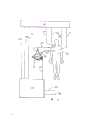
图1是本发明一个实施例的循环维持装置的泵的透视图;Fig. 1 is the perspective view of the pump of the circulation maintaining device of an embodiment of the present invention;
图2是图1所示泵的俯视图;Figure 2 is a top view of the pump shown in Figure 1;
图3是沿图2A-A线的剖视图;Fig. 3 is a sectional view along Fig. 2A-A line;
图4是包括图1至图3的泵的循环维持装置的示意图;Figure 4 is a schematic diagram of a circulation maintenance device comprising the pump of Figures 1 to 3;
图5是图1至图3所示泵的瓣膜处于闭合位置的透视图;Figure 5 is a perspective view of the valve of the pump shown in Figures 1 to 3 in a closed position;
图6是类似于图5的视图,瓣膜处于半开状态;Figure 6 is a view similar to Figure 5 with the valve in a half-open state;
图7是类似于图6的视图,瓣膜处于全开状态;Figure 7 is a view similar to Figure 6 with the valve fully open;
图8是类似于图7的视图,瓣膜处于半闭状态;Figure 8 is a view similar to Figure 7 with the valve in a semi-closed state;
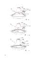
图9示意表示图1至图3所示的泵舒张期开始的状态;Fig. 9 schematically represents the state that the diastolic phase of the pump shown in Fig. 1 to Fig. 3 begins;
图10示意表示类似于图9的泵舒张中期的状态;Figure 10 schematically represents the state of the pump in mid-diastole similar to Figure 9;
图11示意表示类似于图10的泵在舒张后期的状态;Figure 11 schematically represents the state of the pump similar to Figure 10 in late diastole;
图12示意表示类似于图11的泵处于完全舒张的状态;Fig. 12 schematically shows a pump similar to Fig. 11 in a fully relaxed state;
图13示意表示类似于图12的泵处于收缩期开始的状态;Figure 13 schematically shows a pump similar to that of Figure 12 in the state of onset of systole;
图14示意表示类似于图13的泵处于收缩后期的状态;Figure 14 schematically shows a pump similar to Figure 13 in a late systolic state;
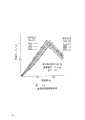
图15是图1至图3所示的泵的收缩率与泵流量的曲线图;Figure 15 is a graph of shrinkage versus pump flow for the pumps shown in Figures 1 to 3;
图16是图1至图3所示泵的泵送时间与游离血浆血红蛋白的曲线图。Figure 16 is a graph of pumping time versus free plasma hemoglobin for the pump shown in Figures 1-3.
图1至图3所示的泵10包括一个泵壳11,一个底座12和安装在它们之间的驱动隔膜13。泵壳11和隔膜13限定一个泵室14,而底座12和隔膜13限定一个驱动室15。The
泵室14一般为圆锥形,圆锥体的底平面靠近底座12,顶17离开底平面一定距离。在泵壳11的底座上有一个安装用环形法兰18,在底座12的顶部有一个与法兰18相配的安装用法兰19。在这种情况下,螺栓和螺母20穿过法兰18和19将泵壳11和底座12固定安装在一起,亦可用一圆环形夹紧环将法兰18和19固定在一起。隔膜13被夹在法兰18和19之间,并用化学物质粘接在法兰18和19上,如图1和图3所示。The
在圆锥形泵室14的顶17上有一个与底座平面16垂直的出口21。靠近泵壳11的底座有一个进口22,在此情况下,进口22以与垂线成45°的角度与底座平面16相交,并与底座12的外部相切。安装在圆筒形瓣膜壳体24中的进口瓣膜23和安装在圆筒形瓣膜壳体26中的出口瓣膜25将在下文结合图5至图8进行描述。用索带(未示出)将瓣膜壳体24和26分别固定在进口22和出口21的位置。On the
底座12有一个将驱动室15与外部泵驱动器相连的口27,用泵驱动器将流体引入驱动室或从驱动室导出,以泵的方式驱动隔膜13。在这种情况下,将口27安装在靠近入口区域的底座12上,它的纵轴以与垂线成45°角与底座平面16相交。该外部驱动器将在下文结合图4加以描述。The
在本发明的优选形式中,泵壳11和底座12是用半透明的环氧树脂制造的,将碳纤维放入进口22、出口21、输送口27和法兰18及19周围的环氧树脂中,以提高环氧树脂的机械强度。在这种情况下,隔膜13是由生物相容材料/聚氯乙烯/生物相容材料的夹层结构制成的。In the preferred form of the invention, the
在零件组装以后,将可能的不连续区域如隔膜13和泵壳11的连接处及瓣膜壳体24、26与泵壳11的连接处有选择地涂敷多链聚氨基甲酸乙酯(一种生物相容材料),来消除任何不连续性。所有与血液接触的表面(包括泵室14的内表面、隔膜13、瓣膜壳体24和26的内部及进口22和出口21的内部)也涂敷生物相容材料。After the parts are assembled, the possible discontinuous areas such as the joints of the
虽然,血液回路中的所有接头的不连续性应被限制到最小程度。因此,进口22和出口21在它们各自的与泵壳体的连接处要尽可能的薄。Nevertheless, all joint discontinuities in the blood circuit should be kept to a minimum. Therefore, the
在这种情况下,泵室14在底座平面16处的内径为75毫米,从底座16到出口21的起点的泵室高度为35毫米。如图3所示,隔膜13是半球形的,在此情况下,它的中心处的深度为20毫米。处于最终收缩位置的隔膜的顶点到出口21的起点间的距离为15毫米。底座12和隔膜13的形状是互补的。In this case, the inner diameter of the
图4是包括图1至图3的泵10的循环维持装置的示意图。泵10的出口21经瓣膜壳体26与管30相连接,并在右心室被维持的情况下进入肺动脉。入口22经瓣膜壳体24与管31相连接,管31通过回收套管连接到病人32的右心房上。FIG. 4 is a schematic diagram of a circulation maintaining device including the
底座12的口27通过导管33连接到控制器34上,控制器34依次与压缩空气供管线35和真空管线36相连接,控制器的作用是驱动隔膜13。
线37把病人32的心电图信号传送给记录器41。线38把病人32的心房压的数值传送给记录器41,线39把病人的支路血流和/或总血流的数值传送给记录器。线40把主动脉压的数值传送给记录器41。线42把从记录器41来的心电图信号传送给控制器34。线43把从记录器41来的心房区传送给控制器34,线44把从记录器41来的总血流的数值传送给控制器34。
因有病心脏的功能反映在左心房压或总血流(心脏的输出流量十支流量)中,通过改变一个心脏工作周期(%的心脏收缩)的泵的工作时间,可将左心房压和总血流量同时保持在一个预定的范围内。Because the function of the diseased heart is reflected in the left atrial pressure or the total blood flow (the output flow of the heart and the branch flow), by changing the working time of the pump in a heart duty cycle (% systole), the left atrial pressure and the Total blood flow is also maintained within a predetermined range.
图5至图8所示的进口瓣膜23有一个位于环46之内的圆盘45。圆盘45有一环形法兰47,它将圆盘45定位在与环46成为一体的下支承48和上支承49之间。The
图5所示的瓣膜是闭合的,此处圆盘45的上表面靠在环46的朝向内部的法兰50上。当瓣膜打开时(见图6),圆盘45摆动并滑动到它的全开位置,如图7所示。在全开位置,法兰47与下支承48接触。当返回到闭合位置时(见图8),圆盘45向回滑入环46并最终地摆回到如图5所示的闭合位置。The valve shown in FIG. 5 is closed, where the upper surface of the
尽管由于结构笨重和其它难题体素瓣膜没有按惯例用于助推装置中,但是将它们用于本发明的泵是可能的。塑料弹性材料也可用来制造瓣膜。Although voxel valves are not routinely used in booster devices due to their bulky construction and other difficulties, it is possible to use them with the pump of the present invention. Plastic elastic materials can also be used to make valves.
图9表示心脏工作周期中的舒张开始阶段,此时进口瓣膜23打开而出口瓣膜24关闭,图9还表示血液按箭头A的方向开始流入时的隔膜13的状态。Fig. 9 shows the beginning of diastole in the working cycle of the heart. At this time, the
图10表示舒张中期,此时血流正在冲洗隔膜13的接合处,泵室11及隔膜13的表面。Figure 10 shows the middle diastole, when the blood flow is flushing the junction of the
图11表示舒张后期,此时进口瓣膜23开始闭合。图11还表示当隔膜13在驱动室15内向下移动时血液形成螺旋运动。Figure 11 shows late diastole, when the
在完全舒张状态下(图12所示)进口关闭,血流的螺旋运动如箭头A所示继续发展。In the state of full relaxation (shown in Figure 12) the inlet is closed and the helical motion of blood flow continues to develop as indicated by arrow A.
图13表示收缩开始,直到出口22打开让血液开始流出。如上所述,使出口22位于圆锥形泵室14的顶点,以便在收缩期间血流如箭头B所示按逐渐收缩的螺旋线形式流出口22。由于隔膜13的位置的原因,此时有较少量回流通过进口瓣膜。Figure 13 shows the onset of contraction until the
图14表示收缩后期,此处进口21被隔膜13阻塞,在这种情况下,有少量的回流通过进口21,并在此处的泵室14的传统停滞区域中有着良好的冲洗作用。最终的收缩如图9所示。Figure 14 shows late systole, where
可将图1至图3所示的泵的流谱特性与普通气动泵的流谱特性进行比较。作为控制选用的普通类型的泵具有近轴的进口和出口。在模拟循环系统中,用加有ambolite颗粒作为示踪剂的水,其流谱可用肉眼观测。可以看到,在本发明的旋涡泵舒张期间,有一股环形进口液流以连贯的旋涡形式平稳地被卷入整个流动区域。The flow spectrum characteristics of the pumps shown in Figures 1 to 3 can be compared with those of ordinary pneumatic pumps. The common type of pump chosen for control has inlet and outlet near the axis. In a simulated circulation system, the flow pattern of water with ambolite particles as a tracer can be observed with the naked eye. It can be seen that during the relaxation period of the vortex pump of the present invention, an annular inlet liquid flow is smoothly drawn into the entire flow area in the form of a coherent vortex.
从入口21以45°角切向进入的血液以及连续的螺旋流谱能很好地冲洗隔膜和泵室的连接处。The blood entering tangentially at a 45° angle from the
在收缩期间,旋涡液流呈螺旋状地汇合并流出顶部出口22。用肉眼观测不到滞流或紊流区域,而且在收缩期间,大部分示踪剂都消失了。在心脏工作的整个周期都能观测到连续的螺旋液流,该液流不受新的周期开始的干扰。During contraction, the vortex flows helically merge and exit the
另一方面,在普通的泵中,由于不规则的流动形式和再循环区域的原因,在每次收缩期间,较少地看到示踪剂从泵中排出。本发明的旋涡泵的优良性能也可通过染料冲洗实验给予充分地证明。用该实验可证明对泵壳和泵壳与隔膜的连接处所产生的优良的冲洗作用。在普通泵中,冲洗是不完全的,可以看到滞流区域。In normal pumps, on the other hand, less tracer is seen exiting the pump during each contraction due to irregular flow patterns and recirculation zones. The excellent performance of the vortex pump of the present invention can also be fully proved by dye flushing experiments. The excellent flushing effect on the pump casing and the junction of the pump casing and the diaphragm can be demonstrated with this test. In normal pumps, the flushing is incomplete and areas of stagnant flow can be seen.
本发明旋涡泵须承受静压试验。隔膜处于最终的舒张状态时,泵的容量为120毫升,而处在最终的收缩状态时,容量减少到45毫升,产生75毫升的计算行程容量。试验压力上升到100磅/平方英寸(5700毫米汞柱)泵没有泄漏或破裂。对隔膜作寿命试验,条件是负载为零,在120冲程/分的脉冲重复频率下隔膜运动到极点。在泵送时间超过三个月后,没观测到损坏现象。The vortex pump of the present invention is subject to a static pressure test. The pump has a capacity of 120 cc when the diaphragm is in its final diastole, and is reduced to 45 cc in its final contraction, yielding a calculated stroke volume of 75 cc. The test pressure was raised to 100 psi (5700 mmHg) and the pump did not leak or rupture. The life test of the diaphragm is carried out under the condition that the load is zero and the diaphragm moves to the extreme at a pulse repetition frequency of 120 strokes/min. After pumping for more than three months, no damage was observed.
本发明的旋涡泵还须在模拟循环回路中承受动压试验,在不同的生理驱动条件下得到特性曲线。典型的特性数据示于图15中,它表示泵的排量与预加负载,驱动压力与收缩率的关系。假如所用的套管的直径越大而长度越短,则所获得的输出流量越高。The vortex pump of the present invention must also undergo a dynamic pressure test in a simulated circulation circuit, and obtain characteristic curves under different physiological driving conditions. Typical characteristic data are shown in Figure 15, which shows pump displacement versus preload, driving pressure versus shrinkage. If a larger diameter and shorter length casing is used, a higher output flow is obtained.
利用两个相同的循环回路,每个回路都充入1.6分升的新鲜羊血,血细胞比容为26%,来完成本发明的旋涡泵和从市场上可得到的泵之间的在玻璃试管内的比较研究。每台泵都在相同的流量条件下操作,血流连续循环21小时,每四小时取一次血样来测量其游离血浆的血红素,结果示于图16中。它清楚地表明,在溶血作用方面这个泵优于普通的泵。Using two identical circulation loops, each filled with 1.6 deciliters of fresh sheep's blood, with a hematocrit of 26%, to complete the transfer between the vortex pump of the present invention and a commercially available pump in a glass test tube A comparative study within. Each pump was operated under the same flow conditions, the blood flow was continuously circulated for 21 hours, blood samples were taken every four hours to measure the hemoglobin in the free plasma, and the results are shown in FIG. 16 . It clearly shows that this pump is superior to the normal pump in terms of hemolysis.
虽然相对于特定形状的圆锥形泵室和切向的倾斜的进口的总体布置对本发明作了描述,但是显然可以作出许多变形而且的确需要作出种种变形来适合实际情况。入口倾斜的优选角度为45°,而这个角度的两边有大约20%至30%的变化幅度就足够了。可以证明,像角度为90°的普通泵一样,角度为零是不能工作的。While the invention has been described with respect to the general arrangement of conically shaped pump chambers and tangentially sloped inlets, it will be apparent that many variations can and will indeed be required to suit the actual situation. The preferred angle of inlet inclination is 45°, and a variation of about 20% to 30% on either side of this angle is sufficient. It can be shown that an angle of zero, like a normal pump at an angle of 90°, will not work.
当改变圆锥的特征用于其它如小儿科用(较小),内部主动脉球状泵(更小)和动脉维持(较大)使用时,可以改变角度。The angle can be changed when changing the characteristics of the cone for other uses such as pediatric (smaller), internal aortic bulb pump (smaller) and arterial maintenance (larger).
在设计制作时,可以作出各种改型并不超出本发明的范围和界线。In design and manufacture, various modifications can be made without departing from the scope and boundaries of the present invention.
Claims (14)
Priority Applications (1)
| Application Number | Priority Date | Filing Date | Title |
|---|---|---|---|
| CN 90106673CN1057786A (en) | 1990-07-06 | 1990-07-06 | Diaphragm pump |
Applications Claiming Priority (1)
| Application Number | Priority Date | Filing Date | Title |
|---|---|---|---|
| CN 90106673CN1057786A (en) | 1990-07-06 | 1990-07-06 | Diaphragm pump |
Publications (1)
| Publication Number | Publication Date |
|---|---|
| CN1057786Atrue CN1057786A (en) | 1992-01-15 |
Family
ID=4880205
Family Applications (1)
| Application Number | Title | Priority Date | Filing Date |
|---|---|---|---|
| CN 90106673PendingCN1057786A (en) | 1990-07-06 | 1990-07-06 | Diaphragm pump |
Country Status (1)
| Country | Link |
|---|---|
| CN (1) | CN1057786A (en) |
Cited By (23)
| Publication number | Priority date | Publication date | Assignee | Title |
|---|---|---|---|---|
| CN101363434B (en)* | 2008-09-08 | 2011-05-11 | 重庆山外山科技有限公司 | Diaphragm metering pump for purifying blood |
| CN102294059A (en)* | 2005-10-03 | 2011-12-28 | 株式会社Jms | Blood storage tank of closed type and extracorporeal blood circulation system using the same |
| CN103143072A (en)* | 2012-12-21 | 2013-06-12 | 北京工业大学 | Auxiliary circulation blood pump adopted in serially connecting operation modes and installing method of auxiliary circulation blood pump |
| CN101420993B (en)* | 2006-03-06 | 2013-07-17 | 索罗泰克公司 | Quick priming connectors for blood circuit |
| CN103261763A (en)* | 2010-10-01 | 2013-08-21 | 柏林心脏有限公司 | Valve, pump system and method for operation of a pump system |
| CN103316386A (en)* | 2013-05-31 | 2013-09-25 | 上海交通大学 | Blood inlet-outlet branch vessel intersected type artificial heart system |
| CN103330963A (en)* | 2013-05-31 | 2013-10-02 | 上海交通大学 | Blood pressure self-adaptive artificial heart system |
| CN104254352A (en)* | 2012-02-16 | 2014-12-31 | 宽塔流体解决方案有限公司 | Blood pump |
| CN104689393A (en)* | 2007-10-12 | 2015-06-10 | 德卡产品有限公司 | Apparatus and methods for hemodialysis |
| CN105597172A (en)* | 2016-02-02 | 2016-05-25 | 丁以群 | Left heart assisting device |
| CN108368839A (en)* | 2015-11-10 | 2018-08-03 | 维培骏公司 | Disposable alternately tangential flow filtration unit |
| US10537671B2 (en) | 2006-04-14 | 2020-01-21 | Deka Products Limited Partnership | Automated control mechanisms in a hemodialysis apparatus |
| US10799628B2 (en) | 2007-02-27 | 2020-10-13 | Deka Products Limited Partnership | Cassette system integrated apparatus |
| US10851769B2 (en) | 2007-02-27 | 2020-12-01 | Deka Products Limited Partnership | Pumping cassette |
| US10871157B2 (en) | 2006-04-14 | 2020-12-22 | Deka Products Limited Partnership | Fluid pumping systems, devices and methods |
| US11110212B2 (en) | 2007-02-27 | 2021-09-07 | Deka Products Limited Partnership | Blood circuit assembly for a hemodialysis system |
| US11154646B2 (en) | 2007-02-27 | 2021-10-26 | Deka Products Limited Partnership | Hemodialysis systems and methods |
| CN113647379A (en)* | 2021-07-18 | 2021-11-16 | 华中科技大学同济医学院附属协和医院 | Non-hemolysis continuous-jumping off-body heart transfer device |
| US11371498B2 (en) | 2018-03-30 | 2022-06-28 | Deka Products Limited Partnership | Liquid pumping cassettes and associated pressure distribution manifold and related methods |
| US11779689B2 (en) | 2011-05-24 | 2023-10-10 | Deka Products Limited Partnership | Blood treatment systems and methods |
| US11890403B2 (en) | 2011-05-24 | 2024-02-06 | Deka Products Limited Partnership | Hemodialysis system |
| US12311086B2 (en) | 2008-01-23 | 2025-05-27 | Deka Products Limited Partnership | Pump cassette and methods for use in medical treatment system using a plurality of fluid lines |
| US12421952B2 (en) | 2013-03-15 | 2025-09-23 | Deka Products Limited Partnership | Reciprocating diaphragm pumps for blood treatment systems and methods |
- 1990
- 1990-07-06CNCN 90106673patent/CN1057786A/enactivePending
Cited By (40)
| Publication number | Priority date | Publication date | Assignee | Title |
|---|---|---|---|---|
| CN102294059A (en)* | 2005-10-03 | 2011-12-28 | 株式会社Jms | Blood storage tank of closed type and extracorporeal blood circulation system using the same |
| CN101420993B (en)* | 2006-03-06 | 2013-07-17 | 索罗泰克公司 | Quick priming connectors for blood circuit |
| US10537671B2 (en) | 2006-04-14 | 2020-01-21 | Deka Products Limited Partnership | Automated control mechanisms in a hemodialysis apparatus |
| US12044229B2 (en) | 2006-04-14 | 2024-07-23 | Deka Products Limited Partnership | Fluid pumping systems, devices and methods |
| US11828279B2 (en) | 2006-04-14 | 2023-11-28 | Deka Products Limited Partnership | System for monitoring and controlling fluid flow in a hemodialysis apparatus |
| US11754064B2 (en) | 2006-04-14 | 2023-09-12 | Deka Products Limited Partnership | Fluid pumping systems, devices and methods |
| US11419965B2 (en) | 2006-04-14 | 2022-08-23 | Deka Products Limited Partnership | Pumping cassette |
| US10871157B2 (en) | 2006-04-14 | 2020-12-22 | Deka Products Limited Partnership | Fluid pumping systems, devices and methods |
| US11793915B2 (en) | 2007-02-27 | 2023-10-24 | Deka Products Limited Partnership | Hemodialysis systems and methods |
| US12044228B2 (en) | 2007-02-27 | 2024-07-23 | Deka Products Limited Partnership | Cassette system integrated apparatus |
| US11779691B2 (en) | 2007-02-27 | 2023-10-10 | Deka Products Limited Partnership | Pumping cassette |
| US11633526B2 (en) | 2007-02-27 | 2023-04-25 | Deka Products Limited Partnership | Cassette system integrated apparatus |
| US12059516B2 (en) | 2007-02-27 | 2024-08-13 | Deka Products Limited Partnership | Blood circuit assembly for a hemodialysis system |
| US10799628B2 (en) | 2007-02-27 | 2020-10-13 | Deka Products Limited Partnership | Cassette system integrated apparatus |
| US10851769B2 (en) | 2007-02-27 | 2020-12-01 | Deka Products Limited Partnership | Pumping cassette |
| US11154646B2 (en) | 2007-02-27 | 2021-10-26 | Deka Products Limited Partnership | Hemodialysis systems and methods |
| US11110212B2 (en) | 2007-02-27 | 2021-09-07 | Deka Products Limited Partnership | Blood circuit assembly for a hemodialysis system |
| CN104689393A (en)* | 2007-10-12 | 2015-06-10 | 德卡产品有限公司 | Apparatus and methods for hemodialysis |
| US12311086B2 (en) | 2008-01-23 | 2025-05-27 | Deka Products Limited Partnership | Pump cassette and methods for use in medical treatment system using a plurality of fluid lines |
| CN101363434B (en)* | 2008-09-08 | 2011-05-11 | 重庆山外山科技有限公司 | Diaphragm metering pump for purifying blood |
| CN103261763A (en)* | 2010-10-01 | 2013-08-21 | 柏林心脏有限公司 | Valve, pump system and method for operation of a pump system |
| US11890403B2 (en) | 2011-05-24 | 2024-02-06 | Deka Products Limited Partnership | Hemodialysis system |
| US11779689B2 (en) | 2011-05-24 | 2023-10-10 | Deka Products Limited Partnership | Blood treatment systems and methods |
| US12220507B2 (en) | 2011-05-24 | 2025-02-11 | Deka Products Limited Partnership | Blood treatment systems and methods |
| CN104254352A (en)* | 2012-02-16 | 2014-12-31 | 宽塔流体解决方案有限公司 | Blood pump |
| CN104254352B (en)* | 2012-02-16 | 2016-12-14 | 宽塔流体解决方案有限公司 | Blood pump |
| CN103143072A (en)* | 2012-12-21 | 2013-06-12 | 北京工业大学 | Auxiliary circulation blood pump adopted in serially connecting operation modes and installing method of auxiliary circulation blood pump |
| CN103143072B (en)* | 2012-12-21 | 2015-06-17 | 北京工业大学 | Auxiliary circulation blood pump adopted in serially connecting operation modes and installing method of auxiliary circulation blood pump |
| US12421952B2 (en) | 2013-03-15 | 2025-09-23 | Deka Products Limited Partnership | Reciprocating diaphragm pumps for blood treatment systems and methods |
| CN103330963B (en)* | 2013-05-31 | 2015-06-03 | 上海交通大学 | Blood pressure self-adaptive artificial heart system |
| CN103316386A (en)* | 2013-05-31 | 2013-09-25 | 上海交通大学 | Blood inlet-outlet branch vessel intersected type artificial heart system |
| CN103330963A (en)* | 2013-05-31 | 2013-10-02 | 上海交通大学 | Blood pressure self-adaptive artificial heart system |
| CN103316386B (en)* | 2013-05-31 | 2015-09-09 | 上海市浦东医院 | Turnover blood arm staggered form artificial heart system |
| US11156219B2 (en) | 2015-11-10 | 2021-10-26 | Repligen Corporation | Disposable alternating tangential flow filtration units |
| CN108368839B (en)* | 2015-11-10 | 2020-01-07 | 维培骏公司 | Disposable Alternating Tangential Flow Filtration Unit |
| CN108368839A (en)* | 2015-11-10 | 2018-08-03 | 维培骏公司 | Disposable alternately tangential flow filtration unit |
| CN105597172A (en)* | 2016-02-02 | 2016-05-25 | 丁以群 | Left heart assisting device |
| US11371498B2 (en) | 2018-03-30 | 2022-06-28 | Deka Products Limited Partnership | Liquid pumping cassettes and associated pressure distribution manifold and related methods |
| US12078162B2 (en) | 2018-03-30 | 2024-09-03 | Deka Products Limited Partnership | Liquid pumping cassettes and associated pressure distribution manifold and related methods |
| CN113647379A (en)* | 2021-07-18 | 2021-11-16 | 华中科技大学同济医学院附属协和医院 | Non-hemolysis continuous-jumping off-body heart transfer device |
Similar Documents
| Publication | Publication Date | Title |
|---|---|---|
| CN1057786A (en) | Diaphragm pump | |
| US5458468A (en) | Diaphragm pump | |
| CN103055363B (en) | Vortex type implantable pulse ventricle assisting blood pump | |
| CN106421947B (en) | A kind of intra-ventricle pulsatory blood pump | |
| JP4016441B2 (en) | Turbo blood pump | |
| US9333284B2 (en) | Heart assist device | |
| US8226712B1 (en) | Total artificial heart system for auto-regulating flow and pressure | |
| CN105597172B (en) | Left ventricular assist device | |
| WO2023177428A1 (en) | Ventricular assist device having pressure sensor embedded durable displacement blood pump | |
| JP5868180B2 (en) | Beatable medical device designed for use in extracorporeal surgery | |
| IE56530B1 (en) | Right ventricular assist device | |
| JP2001508669A (en) | Pulsating flow generation in a heart-lung machine | |
| CN107456616A (en) | Heart analog machine | |
| WO2000072897A1 (en) | Pulse wave generator for cardiopulmonary bypass and extracorporeal oxygenation apparatus | |
| Meyns et al. | Miniaturized implantable rotary blood pump in atrial-aortic position supports and unloads the failing heart | |
| US20060236756A1 (en) | Pulsator device, method of operating same, corresponding system and computer program product | |
| CN112156255A (en) | Magnetic suspension centrifugal blood pump with integrated extracorporeal circulation magnetic wheel | |
| KR102525303B1 (en) | A blood pump and an oxidation system having the same that flows blood in one direction | |
| RU210144U1 (en) | DISC PUMP OF LEFT VENTRICULAR BYPASS TO SUPPORT MECHANICAL HEART WORK | |
| Khodeli et al. | Practical and Theoretical Considerations for ECMO System Development | |
| IL95065A (en) | Diaphragm pump for pumping blood | |
| CN85101745A (en) | artificial heart | |
| JPS59218159A (en) | Sac-shaped blood pump | |
| RU226652U1 (en) | IMPELLER FOR CENTRIFUGAL PUMP OF EXTRACORPORAL MEMBRANE OXYGENATION SYSTEMS WITH SEAL IN THE SIDE CAVITY | |
| Buchnev et al. | heMODYnaMic eValuaTiOn Of a neW PulSaTile flOW GeneraTiOn MeThOD in carDiOPulMOnarY BYPaSS SYSTeMS |
Legal Events
| Date | Code | Title | Description |
|---|---|---|---|
| C06 | Publication | ||
| PB01 | Publication | ||
| C10 | Entry into substantive examination | ||
| SE01 | Entry into force of request for substantive examination | ||
| C53 | Correction of patent for invention or patent application | ||
| CB02 | Change of applicant information | Address after:New South Wales Australia Applicant after:Ann Lois Chang Address before:New South Wales Australia Applicant before:Zhang Renqian | |
| COR | Change of bibliographic data | Free format text:CORRECT: APPLICANT; FROM: ZHANG RENQIAN TO: EN.LUES.ZHANG | |
| C01 | Deemed withdrawal of patent application (patent law 1993) | ||
| WD01 | Invention patent application deemed withdrawn after publication |