CN1057391C - High-density optical-fiber distribution frame - Google Patents
High-density optical-fiber distribution frameDownload PDFInfo
- Publication number
- CN1057391C CN1057391CCN94194854ACN94194854ACN1057391CCN 1057391 CCN1057391 CCN 1057391CCN 94194854 ACN94194854 ACN 94194854ACN 94194854 ACN94194854 ACN 94194854ACN 1057391 CCN1057391 CCN 1057391C
- Authority
- CN
- China
- Prior art keywords
- modules
- module
- adapters
- frame member
- mounting frame
- Prior art date
- Legal status (The legal status is an assumption and is not a legal conclusion. Google has not performed a legal analysis and makes no representation as to the accuracy of the status listed.)
- Expired - Lifetime
Links
- 239000013307optical fiberSubstances0.000titleabstractdescription22
- 239000000835fiberSubstances0.000claimsabstractdescription46
- 230000008054signal transmissionEffects0.000claimsdescription2
- 230000007246mechanismEffects0.000description8
- 210000002105tongueAnatomy0.000description7
- 230000003287optical effectEffects0.000description6
- 239000004033plasticSubstances0.000description6
- 238000005452bendingMethods0.000description5
- 238000002372labellingMethods0.000description3
- 229910052802copperInorganic materials0.000description2
- 239000010949copperSubstances0.000description2
- 238000009434installationMethods0.000description2
- 238000002955isolationMethods0.000description2
- 239000002184metalSubstances0.000description2
- 229910052751metalInorganic materials0.000description2
- 230000004308accommodationEffects0.000description1
- 230000008901benefitEffects0.000description1
- 230000008859changeEffects0.000description1
- 230000000295complement effectEffects0.000description1
- 230000008878couplingEffects0.000description1
- 238000010168coupling processMethods0.000description1
- 238000005859coupling reactionMethods0.000description1
- 230000000881depressing effectEffects0.000description1
- 239000011094fiberboardSubstances0.000description1
- 238000002347injectionMethods0.000description1
- 239000007924injectionSubstances0.000description1
- 239000000463materialSubstances0.000description1
- 239000002991molded plasticSubstances0.000description1
Images


Classifications
- H—ELECTRICITY
- H04—ELECTRIC COMMUNICATION TECHNIQUE
- H04Q—SELECTING
- H04Q1/00—Details of selecting apparatus or arrangements
- H04Q1/02—Constructional details
- H04Q1/14—Distribution frames
- H04Q1/142—Terminal blocks for distribution frames
- G—PHYSICS
- G02—OPTICS
- G02B—OPTICAL ELEMENTS, SYSTEMS OR APPARATUS
- G02B6/00—Light guides; Structural details of arrangements comprising light guides and other optical elements, e.g. couplings
- G02B6/44—Mechanical structures for providing tensile strength and external protection for fibres, e.g. optical transmission cables
- G02B6/4439—Auxiliary devices
- G02B6/444—Systems or boxes with surplus lengths
- G02B6/4452—Distribution frames
- G02B6/44526—Panels or rackmounts covering a whole width of the frame or rack
- G—PHYSICS
- G02—OPTICS
- G02B—OPTICAL ELEMENTS, SYSTEMS OR APPARATUS
- G02B6/00—Light guides; Structural details of arrangements comprising light guides and other optical elements, e.g. couplings
- G02B6/44—Mechanical structures for providing tensile strength and external protection for fibres, e.g. optical transmission cables
- G02B6/4439—Auxiliary devices
- G02B6/444—Systems or boxes with surplus lengths
- G02B6/44528—Patch-cords; Connector arrangements in the system or in the box
- G—PHYSICS
- G02—OPTICS
- G02B—OPTICAL ELEMENTS, SYSTEMS OR APPARATUS
- G02B6/00—Light guides; Structural details of arrangements comprising light guides and other optical elements, e.g. couplings
- G02B6/44—Mechanical structures for providing tensile strength and external protection for fibres, e.g. optical transmission cables
- G02B6/4439—Auxiliary devices
- G02B6/444—Systems or boxes with surplus lengths
- G02B6/4453—Cassettes
- G02B6/4455—Cassettes characterised by the way of extraction or insertion of the cassette in the distribution frame, e.g. pivoting, sliding, rotating or gliding
- H—ELECTRICITY
- H04—ELECTRIC COMMUNICATION TECHNIQUE
- H04Q—SELECTING
- H04Q1/00—Details of selecting apparatus or arrangements
- H04Q1/02—Constructional details
- H04Q1/021—Constructional details using pivoting mechanisms for accessing the interior of the apparatus
- H—ELECTRICITY
- H04—ELECTRIC COMMUNICATION TECHNIQUE
- H04Q—SELECTING
- H04Q1/00—Details of selecting apparatus or arrangements
- H04Q1/02—Constructional details
- H04Q1/023—Constructional details using sliding mechanisms for accessing the interior of the apparatus
- H—ELECTRICITY
- H04—ELECTRIC COMMUNICATION TECHNIQUE
- H04Q—SELECTING
- H04Q1/00—Details of selecting apparatus or arrangements
- H04Q1/02—Constructional details
- H04Q1/06—Cable ducts or mountings specially adapted for exchange installations
- H—ELECTRICITY
- H04—ELECTRIC COMMUNICATION TECHNIQUE
- H04Q—SELECTING
- H04Q1/00—Details of selecting apparatus or arrangements
- H04Q1/02—Constructional details
- H04Q1/06—Cable ducts or mountings specially adapted for exchange installations
- H04Q1/062—Cable ducts or mountings specially adapted for exchange installations vertical management arrangements
- H—ELECTRICITY
- H04—ELECTRIC COMMUNICATION TECHNIQUE
- H04Q—SELECTING
- H04Q1/00—Details of selecting apparatus or arrangements
- H04Q1/02—Constructional details
- H04Q1/06—Cable ducts or mountings specially adapted for exchange installations
- H04Q1/066—Cable ducts or mountings specially adapted for exchange installations arranged on the front side
- H—ELECTRICITY
- H04—ELECTRIC COMMUNICATION TECHNIQUE
- H04Q—SELECTING
- H04Q1/00—Details of selecting apparatus or arrangements
- H04Q1/02—Constructional details
- H04Q1/06—Cable ducts or mountings specially adapted for exchange installations
- H04Q1/068—Cable ducts or mountings specially adapted for exchange installations arranged on the rear side
- G—PHYSICS
- G02—OPTICS
- G02B—OPTICAL ELEMENTS, SYSTEMS OR APPARATUS
- G02B6/00—Light guides; Structural details of arrangements comprising light guides and other optical elements, e.g. couplings
- G02B6/24—Coupling light guides
- G02B6/36—Mechanical coupling means
- G02B6/38—Mechanical coupling means having fibre to fibre mating means
- G02B6/3807—Dismountable connectors, i.e. comprising plugs
- G02B6/381—Dismountable connectors, i.e. comprising plugs of the ferrule type, e.g. fibre ends embedded in ferrules, connecting a pair of fibres
- G02B6/3825—Dismountable connectors, i.e. comprising plugs of the ferrule type, e.g. fibre ends embedded in ferrules, connecting a pair of fibres with an intermediate part, e.g. adapter, receptacle, linking two plugs
- G—PHYSICS
- G02—OPTICS
- G02B—OPTICAL ELEMENTS, SYSTEMS OR APPARATUS
- G02B6/00—Light guides; Structural details of arrangements comprising light guides and other optical elements, e.g. couplings
- G02B6/44—Mechanical structures for providing tensile strength and external protection for fibres, e.g. optical transmission cables
- G02B6/4439—Auxiliary devices
- G02B6/444—Systems or boxes with surplus lengths
- G02B6/4452—Distribution frames
- G02B6/44524—Distribution frames with frame parts or auxiliary devices mounted on the frame and collectively not covering a whole width of the frame or rack
- H—ELECTRICITY
- H04—ELECTRIC COMMUNICATION TECHNIQUE
- H04Q—SELECTING
- H04Q2201/00—Constructional details of selecting arrangements
- H04Q2201/02—Details of frames
- H—ELECTRICITY
- H04—ELECTRIC COMMUNICATION TECHNIQUE
- H04Q—SELECTING
- H04Q2201/00—Constructional details of selecting arrangements
- H04Q2201/80—Constructional details of selecting arrangements in specific systems
- H04Q2201/804—Constructional details of selecting arrangements in specific systems in optical transmission systems
Landscapes
- Engineering & Computer Science (AREA)
- Computer Networks & Wireless Communication (AREA)
- Physics & Mathematics (AREA)
- General Physics & Mathematics (AREA)
- Optics & Photonics (AREA)
- Light Guides In General And Applications Therefor (AREA)
- Yarns And Mechanical Finishing Of Yarns Or Ropes (AREA)
- Mechanical Coupling Of Light Guides (AREA)
- Ropes Or Cables (AREA)
- Sealing Material Composition (AREA)
- Laser Surgery Devices (AREA)
- Paper (AREA)
- Structure Of Telephone Exchanges (AREA)
- Optical Communication System (AREA)
- Connector Housings Or Holding Contact Members (AREA)
- Manufacture, Treatment Of Glass Fibers (AREA)
- Communication Cables (AREA)
- Flexible Shafts (AREA)
- Laying Of Electric Cables Or Lines Outside (AREA)
Abstract
Translated fromChineseDescription
Translated fromChinese1.本发明背景1. Background of the invention
1.本发明的技术领域1. Technical field of the present invention
本发明涉及电讯工业。更具体他说,本发明涉及一种在电讯工业中使用的高密度光纤配线架。This invention relates to the telecommunications industry. More specifically, he states that the present invention relates to a high density optical fiber distribution frame for use in the telecommunications industry.
2.已有技术的描述2. Description of prior art
在电讯工业中,使用光缆来传送信号的情况正在迅速地发展。为了相互连接光学光纤设备,开发出了光纤配线架。在共同转让的美国专利No.4,995,688中示出了一种现有技术的光纤配线架的示例。In the telecommunications industry, the use of optical fiber cables to transmit signals is rapidly developing. In order to interconnect optical fiber equipment, fiber optic distribution frames have been developed. An example of a prior art fiber optic distribution frame is shown in commonly assigned US Patent No. 4,995,688.
美国专利No.4,995,688的光纤配线架包括一所谓的连接器模件(该专利中的构件16),该模件具有一装有多个转接器(102)的前板。为了光学地连接两个光纤光缆,每一转接器(102)的两侧能各连一个光纤连接器(100)。The fiber optic distribution frame of US Patent No. 4,995,688 includes a so-called connector module (
通常,诸转接器(102)的背面设有连接于诸光纤光缆的诸连接器。诸光缆则连接于各种光纤光学设备(诸如,一用来将DS-3信号转换成光学信号的光纤一铜连接器)。Typically, the back of the adapters (102) are provided with connectors for connecting to the fiber optic cables. The optical cables are then connected to various fiber optic devices (such as a fiber-to-copper connector used to convert the DS-3 signal to an optical signal).
在诸转接器背面上的连接均是半永久性的。也就是说,虽然能方便地拆卸诸转接器背面上的诸连接器,但是这些转接器通常是被安装得希望能保持连接器和转接器后侧的连接而不想在以后频繁地改变这种连接。在所述转接器的前侧,所述光纤连接器连接于一光纤电缆(例如,一跨接电缆)用来横向连接于其它光学设备或其它目标上。The connections on the back of the adapters are semi-permanent. That is, although the connectors on the backs of the adapters can be easily removed, these adapters are usually installed in such a way that it is desirable to maintain the connection of the connectors to the rear of the adapter and not to frequently change them later. this connection. On the front side of the adapter, the fiber optic connector is connected to a fiber optic cable (eg, a jumper cable) for cross-connection to other optical devices or other objects.
由于在电讯工业中,纤维光缆使用在不断增加,人们希望能提供一种具有高密度的光纤配线架。所述密度是指每单位体积和单位面积上光纤配线架上所提供的连接的位置的数目。Due to the increasing use of fiber optic cables in the telecommunications industry, it is desirable to provide a fiber optic distribution frame having a high density. The density refers to the number of connection positions provided on the optical fiber distribution frame per unit volume and unit area.
根据上述美国专利4,995,688所制造的产品中,光纤配线架大约具有576个光纤连接器的位置。在工业系统,人们希望使每个配线架的连接器密度增加到大体上超过1,400个。In the product manufactured according to the aforementioned US Patent No. 4,995,688, the optical distribution frame has approximately 576 positions for optical fiber connectors. In industrial systems, it is desirable to increase the connector density to substantially more than 1,400 per patch panel.
高密度光纤配线架的例子包括一框架,该框架由Northern Telecom以光纤管理者的商标销售并在1991年5月出版的第2期中编号为N0.91-004的NorthernTelecom公报上有所描述。其它的例子包括在第2期、编号为2987D-DLH-/89的产品公报上揭示的、由AT&T公司生产的高密度互连系统(HDIC)。An example of a high density fiber optic distribution frame includes a frame sold by Northern Telecom under the trademark Fiber Manager and described in Northern Telecom Bulletin No. 91-004,
现有技术的高密度光纤配线架的一个缺陷在于:当需要接触诸光纤连接器时,这些现有技术的配线架需要移动光纤。例如,Northern Telecom产品将诸光纤和连接器容纳在一模制的塑料盒内。在上述Northern Telecom出版物的第7页上示出了这种塑料盒。所示的这种塑料盒具有12个连接器(组成6对)。为了能接触到12个连接器中年中任何一个连接器,必需将这种塑料盒从框架上拉出大约3至4英寸处。在该处塑料盒下降至一如上述公告中第6页上示出的接触位置,结果,即使仅仅需要接触到一个连接器,所有12个连接器及与12个连接器相连的光纤都要移动。One drawback of prior art high density fiber optic distribution frames is that these prior art distribution frames require the movement of optical fibers when access to fiber optic connectors is required. For example, Northern Telecom products house the optical fibers and connectors in a molded plastic case. Such a plastic case is shown on page 7 of the aforementioned Northern Telecom publication. The plastic box shown has 12 connectors (in 6 pairs). To gain access to any of the 12 connectors, the plastic box must be pulled about 3 to 4 inches from the frame. There the plastic box is lowered to a contact position as shown on page 6 of the above bulletin, with the result that all 12 connectors and the fibers connected to the 12 connectors are moved even though only one connector needs to be accessed .
光纤光缆的不必要或过多的移动是人们所不希望的。当诸光纤光缆移动时,它们易于受到弯曲或其它作用力的影响。当一根光纤弯曲时,该光纤会发生断裂从而导致不能通过该光纤来传送信号。由于诸光纤传送的信号速率极高,故一根光纤的断裂会给数据和电话通信带来明显损失。通常,电讯工业标准规定最小弯曲半径约为
本发明的一个目的在于提供一种光纤配线架,这种配线架具有高密度,能方便地接触到诸光纤连接器,并且当接触诸连接器时,能将诸光纤的移动减小至最小。An object of the present invention is to provide a kind of optical distribution frame, this distribution frame has high density, can contact all optical fiber connectors easily, and when contacting all connectors, can reduce the movement of all optical fibers to minimum.
11.本发明的概述11. Summary of the invention
本发明的一较佳实施例提供了一种信号传送电缆配线系统,它包括:一安装架;以及多个安装在所述安装架上的模件,每一所述模件可动地安装在所述安装架上,每一所述模件包括多个转接器,每一转接器具有相对的两端,用来与一电缆连接器相连接,其特点在于,每一所述转接器均独立可动地安装在所述安装架上能沿着一上下移动直线运动,每一所述模件均具有一纵轴,所述诸模件并列地安装在所述安装架上,并且每一所述纵轴大体上平行于每一所述上、下移动直线,所述多个转接器沿着所述纵轴线性设置,每一所述转接器均可以随其中一个所述模件沿着所述上、下移动直线移动,所述模件的所述多个转接器相互协作可形成一平面。A preferred embodiment of the present invention provides a signal transmission cable distribution system, which includes: a mounting frame; and a plurality of modules installed on the mounting frame, each of the modules is movably installed On the mounting frame, each of the modules includes a plurality of adapters, each of which has opposite ends for connecting with a cable connector, and is characterized in that each of the adapters The connectors are independently and movably installed on the mounting frame and can move along a straight line moving up and down. Each of the modules has a longitudinal axis, and the modules are installed side by side on the mounting frame. And each of the longitudinal axes is substantially parallel to each of the up and down moving straight lines, the plurality of adapters are arranged linearly along the longitudinal axis, and each of the adapters can be arranged with one of the adapters. The module moves along the up-and-down moving line, and the plurality of adapters of the module cooperate with each other to form a plane.
III、附图简要说明III. Brief description of the drawings
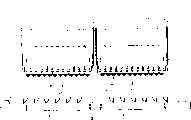
图1是本发明的框架的前视、俯视和右视立体图;Figure 1 is a front view, a top view and a right perspective view of a frame of the present invention;
图2是本发明的由同一安装侧支架连在一起的两个安装架的俯视、前视和右视立体图;Fig. 2 is the top view, front view and right perspective view of two mounting brackets connected together by the same mounting side bracket of the present invention;
图3是图2所示安装架的俯视图;Fig. 3 is a top view of the mounting bracket shown in Fig. 2;
图4是与图2相似的视图,示出了一枢转至一下方位置的右安装架;Figure 4 is a view similar to Figure 2, showing a right mounting bracket pivoted to a lower position;
图5是一从一安装侧支架上拆卸下来的左安装架的俯视、前视和右视立体图;Fig. 5 is a top view, front view and right perspective view of a left mounting bracket disassembled from a mounting side bracket;
图6是图5所示安装架的右视图;Fig. 6 is the right side view of mounting frame shown in Fig. 5;
图7是一含有诸转接器的横向连接底盘的前视、俯视和右视立体图;Figure 7 is a front, top and right perspective view of a transverse connection chassis including adapters;
图8是一金属支承平台的前视、俯视和右视立体图;Fig. 8 is a front view, top view and right perspective view of a metal support platform;
图9是一左定位壁的前视、俯视和右视立体图;Fig. 9 is a front view, top view and right perspective view of a left positioning wall;
图10是图9所示定位壁的右视图;Figure 10 is a right side view of the positioning wall shown in Figure 9;
图11是图9所示定位壁的前端俯视放大图;Fig. 11 is an enlarged top view of the front end of the positioning wall shown in Fig. 9;
图12是一中间定位壁的前视、俯视和右视立体图;Fig. 12 is a front view, top view and right perspective view of an intermediate positioning wall;
图13是图12所示定位壁的右视图;Figure 13 is a right side view of the positioning wall shown in Figure 12;
图14是图12所示定位壁的前端的俯视放大图;Fig. 14 is an enlarged top view of the front end of the positioning wall shown in Fig. 12;
图15是一右定位壁的后视、俯视和左视立体图;Figure 15 is a rear view, a top view and a left perspective view of a right positioning wall;
图16是图15所示定位壁的左视图;Figure 16 is a left side view of the positioning wall shown in Figure 15;
图17是图15所示定位壁的前端的俯视图;Figure 17 is a top view of the front end of the positioning wall shown in Figure 15;
图18是与图7相似的视图,示出了诸经移动的连接器模件;Fig. 18 is a view similar to Fig. 7, showing the connector modules moved;
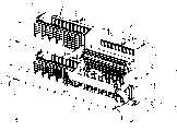
图19是四个安装在一框架上的安装架的前视、俯视和右视立体图,图中一上右侧安装架枢转至一下方的位置;Figure 19 is a front, top, and right perspective view of four mounting brackets mounted on a frame, with an upper right mounting bracket pivoted to a lower position;
图20是图19的右视图;Fig. 20 is the right view of Fig. 19;
图21是本发明的一连接器模件的前视、俯视和右视立体图;21 is a front, top and right perspective view of a connector module of the present invention;
图22是图21所示连接器模件的主视图;Figure 22 is a front view of the connector module shown in Figure 21;
图23是沿图22中线23-23截取的视图;Figure 23 is a view taken along line 23-23 in Figure 22;
图24是沿图22中线24-24截取的视图;Figure 24 is a view taken along line 24-24 in Figure 22;
图25是本发明的、连接于光纤的安装架的前视、俯视和右视立体图;Fig. 25 is a front view, a top view and a right perspective view of the installation frame connected to the optical fiber of the present invention;
图26是图25所示安装架的俯视图。FIG. 26 is a top view of the mounting bracket shown in FIG. 25 .
IV.较佳实施例的描述IV. DESCRIPTION OF THE PREFERRED EMBODIMENTS
现结合附图对本发明的较佳实施例进行描述,在各附图中,相同的构件均采用相同的标号。The preferred embodiments of the present invention will now be described in conjunction with the accompanying drawings. In each of the accompanying drawings, the same components use the same reference numerals.
首先请参阅图1。图1示出了一光纤配线架10。该配线架10包括两个彼此相隔一段距离的侧壁12和14,该两侧壁分上端由一顶壁16连接在一起。连接于顶壁16的前侧的是一用来安放电缆等物的电缆架18。该配线架10的底部设有一底座20,该底座也具有一固定于其上的用来安放电缆等物的电缆架22。侧壁12、14的前缘设有多个电缆夹24用来固定那些在侧壁12、14的前部垂直延伸的光纤光缆。See Figure 1 first. FIG. 1 shows an optical
设置在框架10内部侧壁12和14之间的是多个左、右安装架26、26’(如图1所示)。本说明书在下面有对安装架26、26的具体描述。诸安装架26、26’行将被安装成对齐的两列,每列具有十个安装架,所述两列在水平方向上对齐。应予理解的是,这里安装架的具体数目和它们的对齐方式只是为了说明较佳实施例之用,在框架10内也可以设置其它种种数量和对齐方式的安装架。Disposed between the
图2示出了成对地设置在一共同的安装侧支架28内的安装架26、26’。该安装侧支架28包括用来分别与侧壁12、14连接的第一和第二安装板30、32。第一固定板34、36分别固定于每一安装板30、32,固定板34、36平行设置,并相互隔开地对齐并由一枢转杆38连接在一起。第二固定板40、42(图4中最清楚地示出)也牢固地固定于枢转杆38,并且第二固定板40、42设置在固定板34、36之间并与之平行。第二固定板40设置在第一固定板34的对面,第二固定板42设置在第一固定板36的对面。Figure 2 shows the mounting
图5单独地示出了一左安装架26。除了另有说明的以外,安装架26、26’是相同的并且对其中一个安装架的描述足以说明另一安装架。与安装架26的诸构件相应的安装架26’的诸构件均以相同的标号标示,只是附加了了一撇号“’”以示区别。FIG. 5 shows a left mounting
安装架26包括一金属支承平台44和一塑料模制横向连接的盘架46。所述支承平台44单独地示出在图8中,它包括两个由底板部47分隔开的平行侧壁45、49。底板部47的一前缘设有相互平行的切口51以构成多个支承指53。Mounting
图7和图8单独示出了所述横向连接的盘架46。所述横向连接的盘架46包括一平底座48(该平底座固定于平台44的底板47上)。在平底座48的一后缘处与平底座48一起模制的是诸夹子50,诸夹子有一定的大小从而能咔嗒一声咬合在枢转杆38上以使诸夹子50(并由此使横向连接的盘架46)能围绕枢转扦38的轴线(图2中的X-X)转动或枢转。当安装架26固定在框架10内部时,枢转杆38和轴线X-X均处于水平位置。Figures 7 and 8 show the transversely connected trays 46 in isolation. The transversely connected tray 46 includes a flat base 48 (the flat base is fixed on the
底座48的上表面设有多个三角形壁面,所述三角形壁面具有一左壁面52a、一右壁面52b和多个中间壁面52c。诸壁面在图26中有标号示出并且在图9-17中予以单独地示出。The upper surface of the base 48 is provided with a plurality of triangular walls, and the triangular wall has a
在每一支承指53上均安装有一壁面。当底座48成水平状态时诸壁面52a-52c均呈垂直状态并且每一壁面均大体上垂直于夹子50的枢轴X-X延伸,并且诸壁面52a-52c彼此相互隔开并平行地相耳对齐。因此,壁面52a-52c中每一壁面的相对表面形成了多个分散的沟槽54(图18)。同样,诸壁面52a-52c中每一壁面的相对表面均在其上形成相互平行并彼此隔开的、垂直于底座48延伸的凹槽56。A wall is mounted on each
设置在每一沟槽54内部的是一模件58,从图21-24可以很清楚地看到,每一模件58大体上呈箱形,并具有两侧壁60、62。每一侧壁60、62设有一凸伸的导轨64,该导轨具有一定大小以便能可滑动地承接在诸凹槽56内部。因此,诸导轨62、64均容纳在诸凹槽56内部从而能使每一模件48相对于平台48在箭头所示的方向A(图18)上分别作单独的移动,所述方向A垂直于夹子50的枢轴X-X。当底座48呈水平状态时,方向A是垂直的。Disposed within each channel 54 is a
诸导轨64具有向内朝着侧壁60、62逐渐变细的斜缘。诸凹槽56均制成互补的形状。因此,当诸导轨64容纳在诸凹槽56内部时,诸导轨能够仅仅在诸凹槽56的方向上移动。这种结构为诸壁面52a-52c提供了侧向支承。The
诸模件还包括诸顶壁66和底壁68,这些顶壁和底壁均设有一可释放的锁定机构70,用来将每一模件58沿着方向A独立地锁定在多个固定位置中的任何一个固定位置上。所述锁定机构70包括诸舌片74,诸舌片由铰链件76固定在诸壁面66、68上。应予理解的是每一模件58都是由一种可注塑模制的塑料制成。铰链件76设有一窄中点78(图23)从而当操作者抓住舌片74并使它朝着壁面66、68推动时,使铰链件76的材料能围绕中点78而转动。诸舌片74还设有一后缘80(图23),该后缘自铰链件76向后凸伸。此外,在每一壁面66、68上还设有一止挡件75以限制诸舌片74的行程以防止窄中点78的断裂。The modules also include top and
诸锁定机构70制成一定大小从而当诸模件58位于如图7所示的第一或通常的位置时,诸后缘80对置并紧靠在壁面52a-52c的顶缘和底缘82上。在该位置,诸锁定件74偏置在一锁定位置并以后缘80对置并紧靠在顶缘和底缘82上以防止诸模件58沿着A的方向移动。The locking
通过按压诸舌片74并使它们朝着顶壁66和底壁68的方向推动。诸锁定机构70从它们的锁定位置而移动至一未锁定位置,在该未锁定位置,诸后缘80与顶缘和底缘82脱开。由于相脱开,诸模件58可以独立地向上或向下(即图18中箭头A所示的方向)移动。居中地位于每一壁面52a-52c的顶缘和底缘82中间的是诸凹槽84、85。当每一锁定机构70位于凹槽84、85的区域内时,操作者可以释放锁定机构70从而使它的自然偏置能使得边缘80容纳在诸凹槽84、85内部。因此,每一模件58可以锁定在一较上位置(以下锁定机构70的边缘80容纳在下凹槽85内)或锁定在一较下位置上(以上锁定机构70的边缘80容纳在上凹槽84内部)。By depressing the
每一模件58具有一中空结构,在一较佳实施例中该中空结构具有一定大小而能容纳六个彼此相互紧靠着直线排列的光纤连接器的转接器。在这个示出的较佳实施例中,诸转接器90已为人们所熟知的所谓SC转接器用来将诸SC连接器容纳并保持在每一转接器90的相对两端处从而使每一转接器90能光学地耦合两个光纤连接器。Each
应予理解的是,SC转接器不构成本发明本身的一部分。这种转接器在市场上可以买得到并是众所周知的零件。在于1993年5月30日申请的、共同转让和共同待批的美国专利NO.08/065,139中示出了转接器的例子。同样,应予理解的是,虽然在较佳实施例使用SC转接器90,但是用于其它光纤连接器(例如,FC、D4或其它各种连接器)的其它各种类型的转接器也可以用在模件58中,只需简单地改变一下模件58的内部几何形状以适应不同连接器转接器的不同外部几何形状就可以。It should be understood that the SC adapter does not form part of the invention per se. Such adapters are commercially available and well known parts. An example of an adapter is shown in commonly assigned and co-pending US Patent No. 08/065,139, filed May 30,1993. Also, it should be understood that while
现请再参阅图4和图5。每一横向连接的盘架46的连接于(通过螺栓或其它类似物)诸支承平台44上。左安装架26的侧壁45、49具有一定大小以紧密地贴在壁面42、36上。右安装架26’的侧壁45’、49’具有一定大小以紧密地贴在壁面34、40上。侧壁45、49上具有加弹簧的锁定凸耳103,这些锁定凸耳能被向内拉动以缩进一锁销102(图5)。一旦释放诸凸耳103,诸凸耳103均被弹簧偏置而使诸锁销102能伸出超过侧壁45、49的外表面。固定板34、40、42和36的相对表面上具有诸锁销孔101(图4),诸锁销孔101具有定大小以容纳诸锁销102,从而使支承平台44和横向连接的盘架46可以围绕枢转杆38转动至任何一个旋转位置并固定在该位置之上。图4示出了一处于水平位置的安装架26和一围绕枢转杆38转动至一较下位置的第二安装架26’。Please refer to Fig. 4 and Fig. 5 again now. Each of the transversely connected trays 46 is attached (by bolts or the like) to the
每一支承平台44的前缘设有从侧向板45、49延伸出来的加长侧壁100、102。这些加长侧壁100、102向前延伸超过转接器90的前表面一段足够长的距离以使诸连接器能插在将变得更清楚的转接器90内,这是显而易见的。The front edge of each
诸加长侧壁100、102由一前壁104相连接,从前壁104起向上延伸的是一具有一平整表面的标示板106,该平整表面大体上平行于诸转接器90的前端平面。标示板106的平整表面提供了一能在其上安装一标示条的表面以使操作者能放置识别信息或其它类似物。该标示板106还能保护诸转接器90以及连接器和光纤以免受到损坏。The
连接于前壁104并在标示板106和诸转接器90中间彼此隔开的是多个拱形导向夹108。对于左侧安装架26来说,诸导向夹108均制成拱形以将诸光纤从诸转接器引导至框架的左侧。对于右侧安装架26’来说,导向夹108均被定向以将诸光纤从诸转接器引导至框架的右侧。此外,每一安装架26还设有一弯纤板110以及一相连的导向夹112。弯纤板110使得诸光纤能向下地悬挂穿过导向夹112并且诸弯纤板110能限制光纤的弯曲从而防止过度弯曲。Attached to the
在安装架26的后侧可以设置任何一种用于安放电缆的装置120架。图4中所示的安放电缆的装置120包括多个用于安放电缆的夹子以及用于收绕过量电缆的装置。同样应予理解的是,安装架26的后面区域可以设置种种不同的安放电缆的装置,包括拼接(splice)盘架或其它类似物。Any kind of
现请参阅图25-26,从中可以注意到安装架26被用来进行组织和横向连接多个光纤的情况。光纤130进入安装架26的后部,多余的光纤长度绕在安放电缆的装置120上。光纤130可以来自各种不同类型光纤光设备中的任何一种,诸如光纤一铜连接器。每一光纤130终止于一SC连接器132。连接器132容纳在诸转接器90的后端内部。交叉连接光纤电缆(通常称为跨接线)140穿过夹子112并通过导向夹108而各自朝着诸转接器90的方向过去。每一光纤140终止于一SC连接器142,每一连接器容纳在一转接器90的前端内部从而使诸连接器132中的每一连接器均能与多个连接器142中的一个连接器连接。Referring now to Figures 25-26, it will be noted that a mounting
人们常常需要更换或移动横向连接电缆140。如果希望接触模件58顶部上的三个转接器的诸电缆或诸连接器,操作者可以抓住诸锁定舌片74并向上移动该模件至图25所示的被升起的模件58的位置。在该位置,该模件的顶部上三个连接器中的每一连接器均可以很方便地接触到而不会受到标示条106的干扰。如果需要接触该模件58底部的三个连接器142,操作者可以简单地握住诸舌片74并向下移动连接器直到顶部的舌片74容纳在凹槽84内部以将模件锁定在较下的位置上。在该较下位置,操作者可以较方便地接触到在标示条106下方的底部三个连接器142而不会受到标示条106的干扰。当不需要接触任何一个连接器时,可将模件58放置在它的中间位置,由标示条106和前壁104保护所有的连接器142避免受到撞击或其它干扰。It is often necessary to replace or move the
应予注意的是,为了可以接触到模件58上任何一个连接器142,该模件58只需移动一段极其小的距离。同样,一次仅能移动六个转接器90。由于接触每一连接器时只需要很小的移动,这种极其小的移动使得任何一根光纤光缆受到损坏的可能性都很小。It should be noted that in order to gain access to any one of the
本发明的优点是光纤的移动很小。在已有技术中,当移动一含有几个连接器的盘架时,诸光纤均需轴向移动一段相当大的距离(例如,大约3英寸)。在本发明中,当模件58向上或向下移动(约15英寸)时,光纤几乎没有轴向移动,这是因为通过横向于光纤轴线的光纤的升高或下降移动避免了大部分的移动。An advantage of the invention is that there is very little movement of the fiber. In the prior art, when moving a reel containing several connectors, the fibers had to be axially moved a considerable distance (eg, about 3 inches). In the present invention, when the
虽然背部连接器132是半永久性安装的,但是人们还是希望能接触到连接器132(尤其是在最初安装这些连接器132的时候)。但是,如果希望接触这些背部连接器132,人们可以以接触前部连接器142那样的方式(通过升高或降低诸模件58)接触这些背部连接器。Although the
在某些装置过程中,操作者只能接触到框架10的前部。在这种装置过程中,可以通过安装架26所具有的倾斜特征来接触到安放电缆的装置120。即,为了从框架10的前部接触到安放电缆的装置120,可以向内拉动诸凸耳103以缩回诸锁销102。由于缩回了诸锁销102,整个安装架26能围绕枢转杆38转动至一下方位置,如图4中由安装架26’所示出的那样。在该下方位置,操作者可以面向着框架10的前部很方便地接触到安放电缆的装置120。During some setups, the operator only has access to the front of the
对于本技术领域的熟练人员来说较为明显的是,还可以对本发明作出其它变化,例如,在上述较佳实施例中,模件58中全部六个转接器90都从中间位置向上或向下移动。但是,也可以将模件58一分为二,使上面的半个模件向上移动以使操作者能接触到顶部的三个连接器,井使下面的半个模件独立地向下移动以使操作者能接触到底部的三个连接器。It will be obvious to those skilled in the art that other changes can be made to the present invention. For example, in the preferred embodiment described above, all six
此外,模件58还能带有其它功能,在上述较佳实施例中,模件58只能夹持诸转接器90。但是,诸模件58还能包括其它除了转接器90之外的部件,例如,诸模件58可以容纳诸分光器、诸WDM(波分多工器)或其它设备。虽然转接器90可以与这些改进的设备一同使用,但是转接器90不是必需的(例如,这种改进的模件可以设有光纤输出线)。In addition, the
从以上对本发明的具体描述中,可以了解本发明的目的是如何由一效佳实施例来实现的。但是,本技术领域的熟练人员对所揭示的概念能很容易作出这种变化和等效的变化,因此所有这种变化均拟包括在所附的权利要求书所要求的保护的范围之内。From the above detailed description of the present invention, it can be understood how the purpose of the present invention is achieved by an effective embodiment. However, such changes and equivalent changes to the disclosed concepts can be readily made by those skilled in the art, and all such changes are intended to be included within the scope of protection required by the appended claims.
Claims (10)
Translated fromChineseApplications Claiming Priority (2)
| Application Number | Priority Date | Filing Date | Title |
|---|---|---|---|
| US18097094A | 1994-01-21 | 1994-01-21 | |
| US08/180,970 | 1994-01-21 |
Publications (2)
| Publication Number | Publication Date |
|---|---|
| CN1142268A CN1142268A (en) | 1997-02-05 |
| CN1057391Ctrue CN1057391C (en) | 2000-10-11 |
Family
ID=22662356
Family Applications (1)
| Application Number | Title | Priority Date | Filing Date |
|---|---|---|---|
| CN94194854AExpired - LifetimeCN1057391C (en) | 1994-01-21 | 1994-11-16 | High-density optical-fiber distribution frame |
Country Status (14)
| Country | Link |
|---|---|
| US (4) | US5497444A (en) |
| EP (2) | EP0740803B1 (en) |
| KR (1) | KR100316756B1 (en) |
| CN (1) | CN1057391C (en) |
| AT (2) | ATE176336T1 (en) |
| AU (1) | AU679308B2 (en) |
| CA (1) | CA2181373C (en) |
| DE (2) | DE69416330T2 (en) |
| ES (2) | ES2129192T3 (en) |
| HU (1) | HU216983B (en) |
| PT (1) | PT871047E (en) |
| SG (2) | SG108809A1 (en) |
| TW (1) | TW232757B (en) |
| WO (1) | WO1995020175A1 (en) |
Cited By (2)
| Publication number | Priority date | Publication date | Assignee | Title |
|---|---|---|---|---|
| CN100371755C (en)* | 2002-07-22 | 2008-02-27 | Adc电信股份有限公司 | Fiber management drawers and distribution panels |
| CN107209318A (en)* | 2014-12-14 | 2017-09-26 | 泰勒森特股份有限公司 | High Reliability Robotic Cross-Connect System |
Families Citing this family (391)
| Publication number | Priority date | Publication date | Assignee | Title |
|---|---|---|---|---|
| TW232757B (en)* | 1994-01-21 | 1994-10-21 | Adc Telecommunications Inc | High-density fiber distribution frame |
| WO1996024081A1 (en)* | 1995-01-30 | 1996-08-08 | The Whitaker Corporation | Pedestal and holders for fiber optic cable |
| DE19537290C1 (en)* | 1995-10-06 | 1996-11-28 | Siemens Ag | Light pipe distribution frame for connection of incoming and outgoing optical fibres |
| US5758003A (en)* | 1996-03-15 | 1998-05-26 | Adc Telecommunications, Inc. | High density fiber management |
| DE69713544T2 (en)* | 1996-04-12 | 2003-02-20 | Telephone Cables Ltd., Dagenham | Arrangement of an optical fiber |
| US5740300A (en)* | 1996-05-01 | 1998-04-14 | Scientific-Atlanta, Inc. | Transceiver module support apparatus with fiber management features |
| US5701380A (en)* | 1996-06-24 | 1997-12-23 | Telect, Inc. | Fiber optic module for high density supply of patching and splicing |
| US6000858A (en)* | 1996-07-12 | 1999-12-14 | Bloom; Cary | Apparatus for, and method of, forming a low stress tight fit of an optical fiber to an external element |
| US5971629A (en) | 1996-07-12 | 1999-10-26 | Bloom; Cary | Apparatus and method bonding optical fiber and/or device to external element using compliant material interface |
| US5871559A (en)* | 1996-12-10 | 1999-02-16 | Bloom; Cary | Arrangement for automated fabrication of fiber optic devices |
| US5805757A (en)* | 1996-12-10 | 1998-09-08 | Bloom; Cary | Apparatus and method for preserving optical characteristics of a fiber optic device |
| US5815619A (en)* | 1996-12-10 | 1998-09-29 | Bloom; Cary | Fiber optic connector hermetically terminated |
| US5948134A (en)* | 1996-09-24 | 1999-09-07 | Bloom; Cary | Apparatus for forming a fiber optic coupler by dynamically adjusting pulling speed and heat intensity |
| US5764348A (en)* | 1996-10-01 | 1998-06-09 | Bloom; Cary | Optical switching assembly for testing fiber optic devices |
| US6177985B1 (en) | 1996-10-01 | 2001-01-23 | Cary Bloom | Apparatus and method for testing optical fiber system components |
| US6074101A (en)* | 1996-12-10 | 2000-06-13 | Bloom; Cary | Apparatus for, and method of, forming a low stress tight fit of an optical fiber to an external element |
| US5917975A (en)* | 1996-12-10 | 1999-06-29 | Bloom; Cary | Apparatus for, and method of, forming a low stress tight fit of an optical fiber to an external element |
| US6003341A (en) | 1996-12-10 | 1999-12-21 | Bloom; Cary | Device for making fiber couplers automatically |
| US5970199A (en) | 1996-12-11 | 1999-10-19 | Act Communications, Inc. | Frame for supporting fiber optic cable splices |
| US5758002A (en)* | 1996-12-31 | 1998-05-26 | Siecor Corporation | Routing and storage apparatus for optical fibers |
| USD440210S1 (en) | 1997-08-07 | 2001-04-10 | Ortronics, Inc. | Cable management rack |
| US5987203A (en)* | 1997-10-09 | 1999-11-16 | Lucent Technologies Inc. | Distribution module for optical couplings |
| US5885112A (en)* | 1997-11-17 | 1999-03-23 | Adc Telecommunications, Inc. | Coax connector bay and drawer |
| US5946440A (en)* | 1997-11-17 | 1999-08-31 | Adc Telecommunications, Inc. | Optical fiber cable management device |
| AU2291999A (en)* | 1998-02-20 | 1999-09-06 | N.V. Raychem S.A. | Fibre optic patch panel |
| US5997311A (en)* | 1998-04-24 | 1999-12-07 | Lucent Technologies Inc. | Interconnect and cross-connect equipment panel for telecommunications apparatus |
| US6721482B1 (en)* | 1998-09-10 | 2004-04-13 | Thomas A. Glynn | Telecommunications fiber optic infrastructure |
| US6201919B1 (en)* | 1998-12-16 | 2001-03-13 | Adc Telecommunications, Inc | Fiber distribution frame |
| US6201920B1 (en)* | 1998-12-28 | 2001-03-13 | Siecor Operations, Llc | Fiber optic cable wall mount housing |
| US6223909B1 (en) | 1999-02-12 | 2001-05-01 | Adc Telecommunications, Inc. | Cable management rack for telecommunications equipment |
| US6424781B1 (en)* | 1999-03-01 | 2002-07-23 | Adc Telecommunications, Inc. | Optical fiber distribution frame with pivoting connector panels |
| US6535682B1 (en) | 1999-03-01 | 2003-03-18 | Adc Telecommunications, Inc. | Optical fiber distribution frame with connector modules |
| US6556763B1 (en)* | 1999-03-01 | 2003-04-29 | Adc Telecommunications, Inc. | Optical fiber distribution frame with connector modules |
| US6760531B1 (en) | 1999-03-01 | 2004-07-06 | Adc Telecommunications, Inc. | Optical fiber distribution frame with outside plant enclosure |
| US6356697B1 (en) | 1999-05-04 | 2002-03-12 | Sumitomo Electric Lightwave Corp. | Optical fiber cable distribution shelf with pivotably mounted trays |
| US6543626B1 (en)* | 1999-05-21 | 2003-04-08 | Adc Telecommunications, Inc. | Cable management rack for telecommunication cross-connect systems |
| JP3130021B1 (en)* | 1999-08-06 | 2001-01-31 | 盟友技研株式会社 | Relay connection device |
| US6278830B1 (en)* | 2000-01-12 | 2001-08-21 | Ortronics, Inc. | Bend limiting fiber management clip |
| US6504988B1 (en)* | 2000-01-24 | 2003-01-07 | Adc Telecommunications, Inc. | Cable management panel with sliding drawer |
| US6438310B1 (en) | 2000-01-24 | 2002-08-20 | Adc Telecommunications, Inc. | Cable management panel with sliding drawer |
| CN1398232A (en)* | 2000-02-07 | 2003-02-19 | 特赫鲁赫鲁器材有限公司 | Portable-pente ski tow |
| US6363198B1 (en) | 2000-03-07 | 2002-03-26 | Sumitomo Electric Lightwave Corp. | Optical fiber cable distribution shelf with cable management system |
| US6591053B2 (en) | 2000-03-08 | 2003-07-08 | Panduit Corp. | Fiber optic wall mount cabinet |
| US6418262B1 (en)* | 2000-03-13 | 2002-07-09 | Adc Telecommunications, Inc. | Fiber distribution frame with fiber termination blocks |
| US6712115B2 (en) | 2000-04-14 | 2004-03-30 | Ren Judkins | Headrail for double shade |
| WO2001080389A2 (en)* | 2000-04-17 | 2001-10-25 | Ciena Corporation | Fiber optic cable duct fan-out with bend protection |
| US6647197B1 (en) | 2000-06-02 | 2003-11-11 | Panduit Corp. | Modular latch and guide rail arrangement for use in fiber optic cable management systems |
| US6362422B1 (en) | 2000-06-02 | 2002-03-26 | Michael T. Vavrik | Enclosure for use in fiber optic management systems |
| US6375363B1 (en) | 2000-06-02 | 2002-04-23 | Cisco Technology, Inc. | Multi-part optical safety clip |
| US6584267B1 (en) | 2000-06-02 | 2003-06-24 | Panduit Corp. | Cable management system |
| US6601995B1 (en) | 2000-06-02 | 2003-08-05 | Cisco Technology, Inc | Optical connector with flexible shielding cover |
| US6614978B1 (en) | 2000-06-02 | 2003-09-02 | Panduit Corp. | Slack cable management system |
| US6501899B1 (en) | 2000-06-02 | 2002-12-31 | Panduit Corp. | Vertical cable management system |
| US6389211B1 (en) | 2000-06-09 | 2002-05-14 | Cisco Technology, Inc. | Fiber optic cable storage device |
| US6760530B1 (en) | 2000-06-09 | 2004-07-06 | Cisco Technology, Inc. | Fiber cable connector clip |
| US6511009B1 (en) | 2000-06-09 | 2003-01-28 | Cisco Technology, Inc. | Fiber optic cable spool |
| US6469244B1 (en) | 2000-06-27 | 2002-10-22 | Cisco Technology, Inc. | EMI cable passthrough shield |
| US6526210B1 (en) | 2000-06-27 | 2003-02-25 | Cisco Technology, Inc. | Optical connector retainer panel and system |
| US6487356B1 (en) | 2000-07-31 | 2002-11-26 | Cisco Technology, Inc. | Fiber optic cable segregation and slack storage apparatus and method |
| US6466724B1 (en)* | 2000-08-24 | 2002-10-15 | Nortel Networks Limited | High density fibre optic connector interface |
| US6633717B1 (en) | 2000-09-08 | 2003-10-14 | Telect, Inc. | High density fiber optic cable distribution frame system |
| US6360050B1 (en) | 2000-09-08 | 2002-03-19 | Telect, Inc. | High density fiber distribution tray system |
| US6678455B1 (en) | 2000-09-08 | 2004-01-13 | Telect, Inc. | Fiber optic cable bend radius management system |
| US6400883B1 (en)* | 2000-09-29 | 2002-06-04 | Lucent Technologies Inc. | Fiber distribution frame with integral active electrical panel |
| US6478472B1 (en) | 2001-01-10 | 2002-11-12 | Fitel Usa Corp. | High-density optical connecting block |
| US6845207B2 (en)* | 2001-02-12 | 2005-01-18 | Fiber Optic Network Solutions Corp. | Optical fiber enclosure system |
| US6532332B2 (en) | 2001-02-15 | 2003-03-11 | Adc Telecommunications, Inc. | Cable guide for fiber termination block |
| US6429376B1 (en) | 2001-03-06 | 2002-08-06 | Adc Telecommunications, Inc. | Add-on trough for cable management rack |
| DE20104606U1 (en)* | 2001-03-16 | 2001-05-31 | 3M Innovative Properties Co., St. Paul, Minn. | Assembly tray for connection modules of insulation displacement technology |
| US20020129959A1 (en)* | 2001-03-19 | 2002-09-19 | Petersen Cyle D. | Cable management rack and chassis system |
| US6654536B2 (en)* | 2001-04-12 | 2003-11-25 | Corning Cable Systems Llc | Fiber management frame having connector platform |
| US6533616B2 (en) | 2001-04-13 | 2003-03-18 | Adc Telecommunications, Inc. | DSX jack including sliding rear connector |
| US6830466B2 (en)* | 2001-04-27 | 2004-12-14 | Adc Telecommunications, Inc. | Cross aisle connection panel with movable cable brackets |
| US7172077B2 (en)* | 2001-04-27 | 2007-02-06 | Adc Telecommunications, Inc. | Horizontal cable troughs and tool drawer |
| US6708830B2 (en) | 2001-04-27 | 2004-03-23 | Adc Telecommunications, Inc. | Vertical cable management ring with pivotable section |
| US6823063B2 (en) | 2001-04-27 | 2004-11-23 | Adc Telecommunications, Inc. | Cross-connect module and mount |
| JP4006191B2 (en)* | 2001-05-14 | 2007-11-14 | 大日本スクリーン製造株式会社 | Optical fiber coupling equipment |
| US7079744B2 (en) | 2001-07-06 | 2006-07-18 | Adc Telecommunications, Inc. | Cable management panel with sliding drawer and methods |
| FR2832225B1 (en) | 2001-11-13 | 2004-08-27 | Nexans | HIGH DENSITY OPTICAL DISTRIBUTOR AND METHOD FOR THE GARAGE OF SUCH A DISTRIBUTOR |
| FR2832226B1 (en) | 2001-11-13 | 2004-10-22 | Nexans | OPTICAL FIBER DISTRIBUTION AND CONNECTION MODULE FOR AN OPTICAL DISTRIBUTOR |
| US6591051B2 (en)* | 2001-11-16 | 2003-07-08 | Adc Telecommunications, Inc. | Fiber termination block with angled slide |
| US6652153B2 (en) | 2001-12-07 | 2003-11-25 | Itt Manufacturing Enterprises, Inc. | High density fiber optic connector with individual fiber removal |
| EP1341014A1 (en)* | 2002-02-28 | 2003-09-03 | FITEL USA CORPORATION (a Delaware Corporation) | High-density optical connecting block |
| US6937807B2 (en) | 2002-04-24 | 2005-08-30 | Adc Telecommunications, Inc. | Cable management panel with sliding drawer |
| US6711339B2 (en)* | 2002-05-31 | 2004-03-23 | Adc Telecommunications, Inc. | Fiber management module with cable storage |
| US6950592B1 (en)* | 2002-05-31 | 2005-09-27 | Ciena Corporation | Fiber optic cable management system |
| US6766094B2 (en)* | 2002-06-28 | 2004-07-20 | Corning Cable Systems Llc | Aerial closure for local convergence point |
| US6920273B2 (en) | 2002-08-20 | 2005-07-19 | Adc Telecommunications, Inc. | High density fiber distribution frame |
| US7086539B2 (en) | 2002-10-21 | 2006-08-08 | Adc Telecommunications, Inc. | High density panel with rotating tray |
| US6804447B2 (en)* | 2002-11-05 | 2004-10-12 | Adc Telecommunications, Inc. | Fiber panel with integrated couplers |
| US6865331B2 (en)* | 2003-01-15 | 2005-03-08 | Adc Telecommunications, Inc. | Rotating radius limiter for cable management panel and methods |
| DE10307944B4 (en)* | 2003-02-25 | 2005-08-18 | Berthold Sichert Gmbh | Retractable distribution cabinet |
| US6819856B2 (en)* | 2003-03-05 | 2004-11-16 | Corning Cable Systems Llc | High density fiber optic distribution frame |
| US6853795B2 (en)* | 2003-03-05 | 2005-02-08 | Corning Cable Systems Llc | High density fiber optic distribution frame |
| US7142764B2 (en) | 2003-03-20 | 2006-11-28 | Tyco Electronics Corporation | Optical fiber interconnect cabinets, termination modules and fiber connectivity management for the same |
| DE10313358B3 (en)* | 2003-03-25 | 2004-08-05 | Siemens Ag | Electrical patch panel for mounting on wall or within component module rack supported by fixing angles at opposite ends of patch panel housing |
| GB0307394D0 (en)* | 2003-03-31 | 2003-05-07 | British Telecomm | Telephone exchange cabling |
| WO2004088382A1 (en)* | 2003-03-31 | 2004-10-14 | British Telecommunications Public Limited Company | Optical fiber cable distribution frame |
| US6870734B2 (en) | 2003-05-30 | 2005-03-22 | Adc Telecommunications, Inc. | Fiber containment system |
| US7198409B2 (en) | 2003-06-30 | 2007-04-03 | Adc Telecommunications, Inc. | Fiber optic connector holder and method |
| US7233731B2 (en) | 2003-07-02 | 2007-06-19 | Adc Telecommunications, Inc. | Telecommunications connection cabinet |
| US7171099B2 (en) | 2003-07-31 | 2007-01-30 | Adc Telecommunications, Inc. | Slide arrangement for cable drawer |
| US6885798B2 (en) | 2003-09-08 | 2005-04-26 | Adc Telecommunications, Inc. | Fiber optic cable and furcation module |
| US6983095B2 (en)* | 2003-11-17 | 2006-01-03 | Fiber Optic Network Solutions Corporation | Systems and methods for managing optical fibers and components within an enclosure in an optical communications network |
| US7369741B2 (en) | 2003-11-17 | 2008-05-06 | Fiber Optics Network Solutions Corp. | Storage adapter with dust cap posts |
| US6920274B2 (en) | 2003-12-23 | 2005-07-19 | Adc Telecommunications, Inc. | High density optical fiber distribution frame with modules |
| US7013074B2 (en)* | 2004-02-06 | 2006-03-14 | Corning Cable Systems Llc | Optical connection closure having at least one connector port |
| US6944383B1 (en) | 2004-04-12 | 2005-09-13 | Adc Telecommunications, Inc. | Cable management panel with sliding drawer and methods |
| US20050265013A1 (en)* | 2004-06-01 | 2005-12-01 | Keith Scott M | Modular communications shelf system and methods for using the same |
| US7037143B2 (en)* | 2004-06-09 | 2006-05-02 | Nortel Networks Limited | Front access lan and timing (SATT) |
| NL1026441C2 (en)* | 2004-06-17 | 2005-12-20 | Ruco Ind B V | Device for selectively coupling a number of first glass fibers with a number of second glass fibers. |
| AU2016201870B2 (en)* | 2004-06-18 | 2017-09-28 | Commscope Technologies Llc | Multi-position fiber optic connector holder and method |
| AU2013267049B2 (en)* | 2004-06-18 | 2016-04-28 | Commscope Technologies Llc | Multi-position fiber optic connector holder and method |
| AU2012201616B2 (en)* | 2004-06-18 | 2013-10-03 | Commscope Technologies Llc | Multi-position fiber optic connector holder and method |
| US7218827B2 (en) | 2004-06-18 | 2007-05-15 | Adc Telecommunications, Inc. | Multi-position fiber optic connector holder and method |
| US7376321B2 (en) | 2004-08-09 | 2008-05-20 | Adc Telecommunications, Inc. | Modules including multiple rows of adapters for high density optical fiber distribution frame |
| US7376322B2 (en) | 2004-11-03 | 2008-05-20 | Adc Telecommunications, Inc. | Fiber optic module and system including rear connectors |
| US7171100B2 (en)* | 2004-11-03 | 2007-01-30 | Adc Telecommunications, Inc. | Optical fiber slack storage tray for distribution cabinet |
| US7298946B2 (en)* | 2004-12-22 | 2007-11-20 | Hewlett-Packard Development Company, L.P. | Multi-fiber cable for efficient manageability of optical system |
| US20060193588A1 (en)* | 2005-02-28 | 2006-08-31 | Mertesdorf Daniel R | Fiber access terminal |
| DE102005011208A1 (en)* | 2005-03-09 | 2006-09-21 | Adc Gmbh | Fiber optic cable termination |
| US7194181B2 (en) | 2005-03-31 | 2007-03-20 | Adc Telecommunications, Inc. | Adapter block including connector storage |
| US20060264252A1 (en)* | 2005-05-23 | 2006-11-23 | White Gehrig H | System and method for providing a host console for use with an electronic card game |
| US7260301B2 (en)* | 2005-05-25 | 2007-08-21 | Adc Telecommunications, Inc. | Outside plant fiber distribution enclosure with radial arrangement |
| US7376323B2 (en)* | 2005-05-25 | 2008-05-20 | Adc Telecommunications, Inc. | Fiber optic adapter module |
| US7330625B2 (en)* | 2005-05-25 | 2008-02-12 | Adc Telecommunications, Inc. | Underground enclosure mounting system |
| US7400813B2 (en) | 2005-05-25 | 2008-07-15 | Adc Telecommunications, Inc. | Fiber optic splitter module |
| US7636507B2 (en)* | 2005-06-17 | 2009-12-22 | Adc Telecommunications, Inc. | Compact blind mateable optical splitter |
| US7416349B2 (en)* | 2005-07-27 | 2008-08-26 | Adc Telecommunications, Inc. | Fiber optic adapter module |
| US7397996B2 (en)* | 2005-08-02 | 2008-07-08 | Adc Telecommunications, Inc. | Cable management panel with rear entry |
| US20070036503A1 (en)* | 2005-08-10 | 2007-02-15 | Solheid James J | Fiber optic adapter modules with identification system |
| US7346254B2 (en)* | 2005-08-29 | 2008-03-18 | Adc Telecommunications, Inc. | Fiber optic splitter module with connector access |
| US7623749B2 (en) | 2005-08-30 | 2009-11-24 | Adc Telecommunications, Inc. | Fiber distribution hub with modular termination blocks |
| US7190874B1 (en) | 2005-10-03 | 2007-03-13 | Adc Telecommunications, Inc. | Fiber demarcation box with cable management |
| US7720343B2 (en) | 2006-02-13 | 2010-05-18 | Adc Telecommunications, Inc. | Fiber distribution hub with swing frame and modular termination panels |
| US7418181B2 (en) | 2006-02-13 | 2008-08-26 | Adc Telecommunications, Inc. | Fiber optic splitter module |
| US7816602B2 (en) | 2006-02-13 | 2010-10-19 | Adc Telecommunications, Inc. | Fiber distribution hub with outside accessible grounding terminals |
| US7760984B2 (en) | 2006-05-04 | 2010-07-20 | Adc Telecommunications, Inc. | Fiber distribution hub with swing frame and wrap-around doors |
| US7382961B2 (en) | 2006-05-23 | 2008-06-03 | Telect Inc. | Fiber transitioning |
| US7357667B2 (en)* | 2006-06-22 | 2008-04-15 | Adc Telecommunications, Inc. | Telecommunications patch |
| US7711234B2 (en) | 2006-10-02 | 2010-05-04 | Adc Telecommunications, Inc. | Reskinnable fiber distribution hub |
| US7409137B2 (en)* | 2006-10-04 | 2008-08-05 | Adc Telecommunications, Inc. | Slide arrangement for cable drawer |
| US7437049B2 (en)* | 2006-10-10 | 2008-10-14 | Adc Telecommunications, Inc. | Cable management drawer with access panel |
| US7418182B2 (en)* | 2006-10-10 | 2008-08-26 | Adc Telecommunications, Inc. | Cable management drawer with access panel |
| US7583885B2 (en)* | 2006-11-28 | 2009-09-01 | Adc Telecommunications, Inc. | Fiber distribution enclosure |
| US7496268B2 (en)* | 2006-12-13 | 2009-02-24 | Corning Cable Systems Llc | High density fiber optic hardware |
| US7400814B1 (en) | 2007-01-13 | 2008-07-15 | Furukawa Electric North America, Inc. | Wall-mountable optical fiber and cable management apparatus |
| US7570861B2 (en) | 2007-01-19 | 2009-08-04 | Adc Telecommunications, Inc. | Adapter panel with lateral sliding adapter arrays |
| US7570860B2 (en)* | 2007-01-19 | 2009-08-04 | Adc Telecommunications, Inc. | Adapter panel with lateral sliding adapter arrays |
| US7463812B2 (en) | 2007-01-19 | 2008-12-09 | Adc Telecommunications, Inc. | Overhead cable termination arrangement |
| US8070112B2 (en) | 2007-01-19 | 2011-12-06 | Adc Telecommunications, Inc. | Lateral storage spool for overhead cable pathway |
| US7822310B2 (en)* | 2007-02-28 | 2010-10-26 | Corning Cable Systems Llc | Fiber optic splice trays |
| US7499622B2 (en) | 2007-02-28 | 2009-03-03 | Corning Cable Systems Llc | Fiber optic drop terminals for multiple dwelling units |
| US7522805B2 (en)* | 2007-03-09 | 2009-04-21 | Adc Telecommunications, Inc. | Wall mount distribution arrangement |
| US7715679B2 (en)* | 2007-05-07 | 2010-05-11 | Adc Telecommunications, Inc. | Fiber optic enclosure with external cable spool |
| US7734138B2 (en) | 2007-05-30 | 2010-06-08 | Corning Cable Systems Llc | Fiber optic connector holders |
| US7391954B1 (en) | 2007-05-30 | 2008-06-24 | Corning Cable Systems Llc | Attenuated optical splitter module |
| US20080298743A1 (en)* | 2007-05-31 | 2008-12-04 | Konstantinos Saravanos | Microsplitter module for optical connectivity |
| US20080298748A1 (en)* | 2007-05-31 | 2008-12-04 | Terry Dean Cox | Direct-connect optical splitter module |
| USD561009S1 (en)* | 2007-06-26 | 2008-02-05 | Ernest James Wood | Fiber optic cable support |
| US7787260B2 (en) | 2007-07-09 | 2010-08-31 | Adc Telecommunications, Inc. | Cable management arrangement for a telecommunications cabinet |
| US7590328B2 (en)* | 2007-08-02 | 2009-09-15 | Adc Telecommunications, Inc. | Fiber termination block with splitters |
| US7756379B2 (en) | 2007-08-06 | 2010-07-13 | Adc Telecommunications, Inc. | Fiber optic enclosure with internal cable spool |
| MX2010001515A (en)* | 2007-08-09 | 2010-03-10 | Belden Cdt Canada Inc | TELESCOPIC CONNECTOR ASSEMBLY. |
| US7869682B2 (en) | 2007-09-05 | 2011-01-11 | Adc Telecommunications, Inc. | Fiber optic enclosure with tear-away spool |
| US8798427B2 (en) | 2007-09-05 | 2014-08-05 | Corning Cable Systems Llc | Fiber optic terminal assembly |
| EP2573602B1 (en)* | 2007-09-06 | 2014-07-09 | Prysmian S.p.A. | Modular system and methods for connecting an external communication network to a user network of a building |
| US7809230B2 (en)* | 2007-09-25 | 2010-10-05 | Ksaria Corporation | Apparatus for shaping the end of an optical fiber |
| US7536075B2 (en) | 2007-10-22 | 2009-05-19 | Adc Telecommunications, Inc. | Wavelength division multiplexing module |
| US7885505B2 (en)* | 2007-10-22 | 2011-02-08 | Adc Telecommunications, Inc. | Wavelength division multiplexing module |
| US8179684B2 (en)* | 2007-10-29 | 2012-05-15 | Adc Telecommunications, Inc. | Sliding adapter panel with living hinge and forward/rearward locking |
| US7751672B2 (en) | 2007-10-31 | 2010-07-06 | Adc Telecommunications, Inc. | Low profile fiber distribution hub |
| US8229265B2 (en) | 2007-11-21 | 2012-07-24 | Adc Telecommunications, Inc. | Fiber distribution hub with multiple configurations |
| US8238709B2 (en) | 2007-12-18 | 2012-08-07 | Adc Telecommunications, Inc. | Multi-configuration mounting system for fiber distribution hub |
| US8087621B2 (en)* | 2007-12-20 | 2012-01-03 | Airbus Deutschland Gmbh | Holder for fixing components, in particular lines, inside an aircraft without using holes |
| US8263867B2 (en)* | 2008-01-07 | 2012-09-11 | Chatsworth Products, Inc. | Cable management accessories |
| SE535066C2 (en)* | 2008-01-07 | 2012-04-03 | Chatsworth Prod Inc | Vertical cable management device |
| EP2238492A2 (en)* | 2008-01-07 | 2010-10-13 | Chatsworth Products, Inc. | Apparatus and method for organizing cables in a cabinet |
| US8107816B2 (en) | 2008-01-29 | 2012-01-31 | Adc Telecommunications, Inc. | Wavelength division multiplexing module |
| US7822311B2 (en)* | 2008-02-22 | 2010-10-26 | Canadian Imperial Bank Of Commerce | High density telecommunications chassis with cable management structure |
| US8270796B2 (en)* | 2008-03-04 | 2012-09-18 | Adc Telecommunications, Inc. | Multi-port adapter block |
| US7715682B2 (en)* | 2008-03-04 | 2010-05-11 | Adc Telecommunications, Inc. | Fiber distribution hub having an adjustable plate |
| US7889961B2 (en) | 2008-03-27 | 2011-02-15 | Corning Cable Systems Llc | Compact, high-density adapter module, housing assembly and frame assembly for optical fiber telecommunications |
| US7764859B2 (en)* | 2008-03-28 | 2010-07-27 | Adc Telecommunications, Inc. | Universal cable management panel |
| USD577573S1 (en) | 2008-03-31 | 2008-09-30 | Ernest James Wood | Fiber optic cable support |
| USD574223S1 (en) | 2008-03-31 | 2008-08-05 | Ernest James Wood | Fiber optic cable support |
| US7876993B2 (en)* | 2008-05-05 | 2011-01-25 | Adc Telecommunications, Inc. | Drawer arrangement with rack and pinion |
| WO2009137410A1 (en) | 2008-05-06 | 2009-11-12 | Corindus Ltd. | Catheter system |
| EP2285546A4 (en)* | 2008-05-27 | 2014-03-12 | Adc Telecommunications Inc | SYSTEMS, METHODS AND TOOLS FOR MOLDING FLEXIBLE EXTRUDED CABLES |
| GB0812260D0 (en)* | 2008-07-04 | 2008-08-13 | Tyco Electronics Raychem Nv | Optical fibre coupling device and method |
| US7903922B2 (en)* | 2008-08-07 | 2011-03-08 | Fujikura Ltd. | Optical connector holder and optical termination cabinet, and method of optical fiber wiring in optical termination cabinet |
| ES2560802T3 (en) | 2008-08-27 | 2016-02-22 | Adc Telecommunications, Inc. | Fiber optic adapter with integrally molded bushing alignment structure |
| US11294136B2 (en) | 2008-08-29 | 2022-04-05 | Corning Optical Communications LLC | High density and bandwidth fiber optic apparatuses and related equipment and methods |
| US8326107B2 (en) | 2008-08-29 | 2012-12-04 | Corning Cable Systems Llc | Rear-slidable extension in a fiber optic equipment tray |
| US8184938B2 (en)* | 2008-08-29 | 2012-05-22 | Corning Cable Systems Llc | Rear-installable fiber optic modules and equipment |
| US7945135B2 (en)* | 2008-08-29 | 2011-05-17 | Corning Cable Systems Llc | Telescoping fiber optic module and related equipment |
| US8452148B2 (en)* | 2008-08-29 | 2013-05-28 | Corning Cable Systems Llc | Independently translatable modules and fiber optic equipment trays in fiber optic equipment |
| US7856166B2 (en) | 2008-09-02 | 2010-12-21 | Corning Cable Systems Llc | High-density patch-panel assemblies for optical fiber telecommunications |
| US8290330B2 (en) | 2008-09-05 | 2012-10-16 | Adc Gmbh | Patch panel assembly |
| EP2335461B9 (en) | 2008-09-05 | 2016-07-13 | Tyco Electronics Services GmbH | Frame with cable management |
| US8265447B2 (en)* | 2008-09-16 | 2012-09-11 | Adc Telecommunications, Inc. | Modular fiber optic enclosure with external cable spool |
| JP5052467B2 (en)* | 2008-09-18 | 2012-10-17 | 矢崎総業株式会社 | Optical distribution board |
| CN102209921B (en) | 2008-10-09 | 2015-11-25 | 康宁光缆系统有限公司 | There is the fibre-optic terminus supported from the adapter panel of the input and output optical fiber of optical splitters |
| US8315497B2 (en)* | 2008-10-27 | 2012-11-20 | Adc Telecommunications, Inc. | Universal sliding adapter pack |
| US8879882B2 (en) | 2008-10-27 | 2014-11-04 | Corning Cable Systems Llc | Variably configurable and modular local convergence point |
| US7876995B2 (en)* | 2008-10-29 | 2011-01-25 | Commscope, Inc. Of North Carolina | Telecommunications patching systems with obliquely-angled patching modules |
| WO2010059623A1 (en) | 2008-11-21 | 2010-05-27 | Adc Telecommunications, Inc. | Fiber optic telecommunications module |
| WO2010080745A1 (en)* | 2009-01-08 | 2010-07-15 | Afl Telecommunications Llc | Field terminated fiber patch panel for rack and wall mounting |
| CN102282495B (en)* | 2009-01-15 | 2015-04-22 | Adc电信公司 | Fiber optic module, chassis and adapter |
| US8014646B2 (en)* | 2009-01-26 | 2011-09-06 | Commscope, Inc. Of North Carolina | Telecommunications patching systems with high density patching modules |
| EP2221932B1 (en) | 2009-02-24 | 2011-11-16 | CCS Technology Inc. | Holding device for a cable or an assembly for use with a cable |
| US20100220967A1 (en)* | 2009-02-27 | 2010-09-02 | Cooke Terry L | Hinged Fiber Optic Module Housing and Module |
| EP2237091A1 (en)* | 2009-03-31 | 2010-10-06 | Corning Cable Systems LLC | Removably mountable fiber optic terminal |
| US8897637B2 (en) | 2009-04-22 | 2014-11-25 | Adc Gmbh | Method and arrangement for identifying at least one object |
| US8699838B2 (en) | 2009-05-14 | 2014-04-15 | Ccs Technology, Inc. | Fiber optic furcation module |
| JP5706399B2 (en)* | 2009-05-21 | 2015-04-22 | コーニング ケーブル システムズ リミテッド ライアビリティ カンパニー | Fiber optic equipment supporting movable fiber optic equipment trays and modules, related equipment and methods |
| US9075216B2 (en) | 2009-05-21 | 2015-07-07 | Corning Cable Systems Llc | Fiber optic housings configured to accommodate fiber optic modules/cassettes and fiber optic panels, and related components and methods |
| AU2015203581A1 (en)* | 2009-05-21 | 2015-07-23 | Corning Optical Communications LLC | Fiber optic equipment supporting moveable fiber optic equipment tray(s) and module(s), and related equipment and methods |
| US8538226B2 (en) | 2009-05-21 | 2013-09-17 | Corning Cable Systems Llc | Fiber optic equipment guides and rails configured with stopping position(s), and related equipment and methods |
| WO2010148325A1 (en) | 2009-06-19 | 2010-12-23 | Corning Cable Systems Llc | High fiber optic cable packing density apparatus |
| US8712206B2 (en) | 2009-06-19 | 2014-04-29 | Corning Cable Systems Llc | High-density fiber optic modules and module housings and related equipment |
| EP2443497B1 (en) | 2009-06-19 | 2020-03-04 | Corning Cable Systems LLC | High density and bandwidth fiber optic apparatus |
| ES2403007A1 (en)* | 2009-07-01 | 2013-05-13 | Adc Telecommunications, Inc | Wall-mounted fiber distribution hub |
| KR101820175B1 (en) | 2009-07-21 | 2018-01-18 | 콤스코프 커넥티비티 엘엘씨 | Rapid universal rack mount enclosure |
| EP2470934A1 (en) | 2009-08-26 | 2012-07-04 | Commscope Inc. of North Carolina | Datacommunications/telecommunications patching systems with integrated connectivity module |
| US8467651B2 (en) | 2009-09-30 | 2013-06-18 | Ccs Technology Inc. | Fiber optic terminals configured to dispose a fiber optic connection panel(s) within an optical fiber perimeter and related methods |
| WO2011047288A1 (en) | 2009-10-16 | 2011-04-21 | Adc Telecommunications, Inc. | Managed connectivity in fiber optic systems and methods thereof |
| US8625950B2 (en) | 2009-12-18 | 2014-01-07 | Corning Cable Systems Llc | Rotary locking apparatus for fiber optic equipment trays and related methods |
| EP2531877B9 (en)* | 2010-02-02 | 2016-07-13 | ADC Telecommunications, Inc. | Fiber optic cable bundle with staggered connectors |
| US8992099B2 (en) | 2010-02-04 | 2015-03-31 | Corning Cable Systems Llc | Optical interface cards, assemblies, and related methods, suited for installation and use in antenna system equipment |
| CN102933999B (en)* | 2010-02-05 | 2014-09-17 | 深圳世纪人通讯设备有限公司 | Adapter holder module |
| WO2011100613A1 (en) | 2010-02-12 | 2011-08-18 | Adc Telecommunications, Inc. | Communications bladed system |
| CN102870021B (en) | 2010-03-02 | 2015-03-11 | 蒂安电子服务有限责任公司 | Fibre-optic telecommunication module |
| US8649649B2 (en) | 2010-03-03 | 2014-02-11 | Adc Telecommunications, Inc. | Fiber distribution hub with connectorized stub cables |
| US9547144B2 (en) | 2010-03-16 | 2017-01-17 | Corning Optical Communications LLC | Fiber optic distribution network for multiple dwelling units |
| US20110235986A1 (en)* | 2010-03-24 | 2011-09-29 | Adc Telecommunications, Inc. | Optical fiber drawer with connectorized stub cable |
| US8913866B2 (en) | 2010-03-26 | 2014-12-16 | Corning Cable Systems Llc | Movable adapter panel |
| US8837940B2 (en) | 2010-04-14 | 2014-09-16 | Adc Telecommunications, Inc. | Methods and systems for distributing fiber optic telecommunication services to local areas and for supporting distributed antenna systems |
| US8792767B2 (en) | 2010-04-16 | 2014-07-29 | Ccs Technology, Inc. | Distribution device |
| CA2796221C (en) | 2010-04-16 | 2018-02-13 | Ccs Technology, Inc. | Sealing and strain relief device for data cables |
| EP2381284B1 (en) | 2010-04-23 | 2014-12-31 | CCS Technology Inc. | Under floor fiber optic distribution device |
| US9239442B2 (en) | 2010-04-27 | 2016-01-19 | Adc Communications (Shanghai) Co., Ltd. | Fiber optic module and chassis |
| US9075217B2 (en) | 2010-04-30 | 2015-07-07 | Corning Cable Systems Llc | Apparatuses and related components and methods for expanding capacity of fiber optic housings |
| US9720195B2 (en) | 2010-04-30 | 2017-08-01 | Corning Optical Communications LLC | Apparatuses and related components and methods for attachment and release of fiber optic housings to and from an equipment rack |
| US9632270B2 (en) | 2010-04-30 | 2017-04-25 | Corning Optical Communications LLC | Fiber optic housings configured for tool-less assembly, and related components and methods |
| EP2564251B1 (en)* | 2010-04-30 | 2017-06-07 | Corning Optical Communications LLC | Fiber optic housings with removable panel clips |
| US8879881B2 (en) | 2010-04-30 | 2014-11-04 | Corning Cable Systems Llc | Rotatable routing guide and assembly |
| US9519118B2 (en) | 2010-04-30 | 2016-12-13 | Corning Optical Communications LLC | Removable fiber management sections for fiber optic housings, and related components and methods |
| AU2015224449B2 (en)* | 2010-04-30 | 2017-10-12 | Corning Optical Communications LLC | Fiber optic housings with removable panel clips |
| US8660397B2 (en) | 2010-04-30 | 2014-02-25 | Corning Cable Systems Llc | Multi-layer module |
| US8705926B2 (en) | 2010-04-30 | 2014-04-22 | Corning Optical Communications LLC | Fiber optic housings having a removable top, and related components and methods |
| WO2011140461A2 (en) | 2010-05-07 | 2011-11-10 | Adc Telecommunications, Inc. | Fiber distribution hub with pass-through interfaces |
| WO2011146717A2 (en) | 2010-05-19 | 2011-11-24 | Adc Telecommunications, Inc. | Lashing together multiple fiber optic telecommunications cables |
| DE202010007778U1 (en)* | 2010-06-09 | 2010-10-07 | CCS Technology, Inc., Wilmington | Device for handling data conductors |
| AU2010355632B2 (en) | 2010-06-18 | 2014-09-18 | Adc Communications (Shanghai) Co., Ltd. | Fiber optic distribution terminal and method of deploying fiber distribution cable |
| CN110174737A (en) | 2010-06-23 | 2019-08-27 | Adc电信公司 | Telecommunication assembly |
| CN101923197A (en)* | 2010-08-04 | 2010-12-22 | 南京华脉科技有限公司 | Main distribution frame for fiber |
| GB2485133B (en)* | 2010-08-09 | 2015-03-04 | Fibrefab Ltd | Cable support assembly including a cable interconnect module |
| US8254738B2 (en) | 2010-08-27 | 2012-08-28 | Ksaria Corporation | Methods and systems for efficient installation of cables in watercraft |
| US8718436B2 (en) | 2010-08-30 | 2014-05-06 | Corning Cable Systems Llc | Methods, apparatuses for providing secure fiber optic connections |
| US8787023B2 (en) | 2010-09-10 | 2014-07-22 | Chatsworth Products, Inc. | Rail mounting clamp for electronic equipment enclosure |
| US8901438B2 (en) | 2010-09-10 | 2014-12-02 | Chatsworth Products, Inc. | Electronic equipment cabinet structure |
| EP2429272A2 (en) | 2010-09-10 | 2012-03-14 | Chatsworth Products, Inc. | Cable pass-through panel for electronic equipment enclosure |
| WO2012054454A2 (en) | 2010-10-19 | 2012-04-26 | Corning Cable Systems Llc | Transition box for multiple dwelling unit fiber optic distribution network |
| US9279951B2 (en) | 2010-10-27 | 2016-03-08 | Corning Cable Systems Llc | Fiber optic module for limited space applications having a partially sealed module sub-assembly |
| US9116324B2 (en) | 2010-10-29 | 2015-08-25 | Corning Cable Systems Llc | Stacked fiber optic modules and fiber optic equipment configured to support stacked fiber optic modules |
| US8662760B2 (en) | 2010-10-29 | 2014-03-04 | Corning Cable Systems Llc | Fiber optic connector employing optical fiber guide member |
| US8670644B2 (en)* | 2010-11-23 | 2014-03-11 | Commscope, Inc. Of North Carolina | Manifold for managing fiber optic cable and structures and systems therefor |
| CA2819235C (en) | 2010-11-30 | 2018-01-16 | Corning Cable Systems Llc | Fiber device holder and strain relief device |
| EP2646866B1 (en)* | 2010-12-01 | 2017-09-13 | 3M Innovative Properties Company | Fiber organizer and distribution box |
| GB2501629A (en) | 2011-01-27 | 2013-10-30 | Commscope Inc | Datacommunications/telecommunications patching systems with bundled patch cord assembly |
| WO2012106510A2 (en) | 2011-02-02 | 2012-08-09 | Corning Cable Systems Llc | Dense fiber optic connector assemblies and related connectors and cables suitable for establishing optical connections for optical backplanes in equipment racks |
| US9182563B2 (en) | 2011-03-31 | 2015-11-10 | Adc Telecommunications, Inc. | Adapter plate for fiber optic module |
| WO2012149020A2 (en) | 2011-04-25 | 2012-11-01 | Adc Telecommunications, Inc. | Rack and chassis for fiber optic sliding adapter modules |
| US9008485B2 (en) | 2011-05-09 | 2015-04-14 | Corning Cable Systems Llc | Attachment mechanisms employed to attach a rear housing section to a fiber optic housing, and related assemblies and methods |
| CA2877896C (en) | 2011-06-24 | 2020-07-21 | Adc Telecommunications, Inc. | Fiber termination enclosure with modular plate assemblies |
| EP3012675A3 (en) | 2011-06-29 | 2016-08-10 | CCS Technology Inc. | Handling device for connector adapters for connections between data transmission cables |
| EP2541293B1 (en) | 2011-06-29 | 2014-05-07 | CCS Technology, Inc. | Adapter mount for fibre connectors with clamping pin received in clamping base |
| AU2012275598A1 (en) | 2011-06-30 | 2014-01-16 | Corning Optical Communications LLC | Fiber optic equipment assemblies employing non-U-width-sized housings and related methods |
| US8953924B2 (en) | 2011-09-02 | 2015-02-10 | Corning Cable Systems Llc | Removable strain relief brackets for securing fiber optic cables and/or optical fibers to fiber optic equipment, and related assemblies and methods |
| WO2013033890A1 (en) | 2011-09-06 | 2013-03-14 | Adc Telecommunications, Inc. | Adapter for fiber optic module |
| US9417418B2 (en) | 2011-09-12 | 2016-08-16 | Commscope Technologies Llc | Flexible lensed optical interconnect device for signal distribution |
| WO2013039783A2 (en) | 2011-09-16 | 2013-03-21 | Adc Telecommunciations, Inc. | Fiber optic cable packaging management |
| US8457464B2 (en) | 2011-09-26 | 2013-06-04 | Hubbell Incorporated | Cable enclosure and radius-limiting cable guide with integral magnetic door catch |
| US8770861B2 (en) | 2011-09-27 | 2014-07-08 | Tyco Electronics Corporation | Outside plant termination enclosure |
| US9239428B2 (en) | 2011-09-28 | 2016-01-19 | Ksaria Corporation | Epoxy dispensing system and dispensing tip used therewith |
| US9106981B2 (en) | 2011-10-03 | 2015-08-11 | Tyco Electronics Uk Ltd | Aggregation enclosure for elevated, outdoor locations |
| US9146376B2 (en) | 2011-10-07 | 2015-09-29 | Adc Telecommunications, Inc. | Rack and chassis for fiber optic sliding adapter modules |
| CN103975264B (en) | 2011-10-07 | 2015-09-16 | Adc电信公司 | Slidable fiber optic connection module with cable slack management |
| US9170391B2 (en) | 2011-10-07 | 2015-10-27 | Adc Telecommunications, Inc. | Slidable fiber optic connection module with cable slack management |
| RU2611105C2 (en) | 2011-10-07 | 2017-02-21 | Адс Телекоммьюникейшнз, Инк. | Fibre-optic cartridge, system and method |
| US9002166B2 (en) | 2011-10-07 | 2015-04-07 | Adc Telecommunications, Inc. | Slidable fiber optic connection module with cable slack management |
| US9097872B2 (en) | 2011-11-08 | 2015-08-04 | Optical Cable Corporation | High density telecommunications patching system and cassettes |
| US9038832B2 (en) | 2011-11-30 | 2015-05-26 | Corning Cable Systems Llc | Adapter panel support assembly |
| US9219546B2 (en) | 2011-12-12 | 2015-12-22 | Corning Optical Communications LLC | Extremely high frequency (EHF) distributed antenna systems, and related components and methods |
| US9188760B2 (en) | 2011-12-22 | 2015-11-17 | Adc Telecommunications, Inc. | Mini rapid delivery spool |
| US9075203B2 (en) | 2012-01-17 | 2015-07-07 | Adc Telecommunications, Inc. | Fiber optic adapter block |
| US9075220B2 (en)* | 2012-01-27 | 2015-07-07 | Commscope, Inc. Of North Carolina | Optical fiber module with mounting block for securing an optical fiber connector |
| US20130215581A1 (en) | 2012-01-27 | 2013-08-22 | Chatsworth Products, Inc. | Board-mounted circuit breakers for electronic equipment enclosures |
| US9054449B2 (en) | 2012-01-27 | 2015-06-09 | Chatsworth Products, Inc. | Cable retention system for power distribution unit |
| US8882536B2 (en) | 2012-01-27 | 2014-11-11 | Chatsworth Products, Inc. | Power distribution unit with interchangeable outlet adapter types |
| US9494757B2 (en)* | 2012-02-29 | 2016-11-15 | Commscope Technologies Llc | Fiber optic cable packaging arrangement |
| US10110307B2 (en) | 2012-03-02 | 2018-10-23 | Corning Optical Communications LLC | Optical network units (ONUs) for high bandwidth connectivity, and related components and methods |
| US9004778B2 (en) | 2012-06-29 | 2015-04-14 | Corning Cable Systems Llc | Indexable optical fiber connectors and optical fiber connector arrays |
| US9250409B2 (en) | 2012-07-02 | 2016-02-02 | Corning Cable Systems Llc | Fiber-optic-module trays and drawers for fiber-optic equipment |
| US9049500B2 (en) | 2012-08-31 | 2015-06-02 | Corning Cable Systems Llc | Fiber optic terminals, systems, and methods for network service management |
| US9042702B2 (en) | 2012-09-18 | 2015-05-26 | Corning Cable Systems Llc | Platforms and systems for fiber optic cable attachment |
| US10082636B2 (en) | 2012-09-21 | 2018-09-25 | Commscope Technologies Llc | Slidable fiber optic connection module with cable slack management |
| US9146362B2 (en) | 2012-09-21 | 2015-09-29 | Adc Telecommunications, Inc. | Insertion and removal tool for a fiber optic ferrule alignment sleeve |
| US9195021B2 (en) | 2012-09-21 | 2015-11-24 | Adc Telecommunications, Inc. | Slidable fiber optic connection module with cable slack management |
| US9146374B2 (en) | 2012-09-28 | 2015-09-29 | Adc Telecommunications, Inc. | Rapid deployment packaging for optical fiber |
| NZ706687A (en) | 2012-09-28 | 2017-09-29 | Adc Telecommunications Inc | Fiber optic cassette |
| US9223094B2 (en) | 2012-10-05 | 2015-12-29 | Tyco Electronics Nederland Bv | Flexible optical circuit, cassettes, and methods |
| US8909019B2 (en) | 2012-10-11 | 2014-12-09 | Ccs Technology, Inc. | System comprising a plurality of distribution devices and distribution device |
| ES2551077T3 (en) | 2012-10-26 | 2015-11-16 | Ccs Technology, Inc. | Fiber optic management unit and fiber optic distribution device |
| ES1141660Y (en) | 2012-12-19 | 2015-10-14 | Tyco Electronics Raychem Bvba | Distribution device with incrementally added dividers |
| CN105074525A (en) | 2013-01-29 | 2015-11-18 | 泰科电子瑞侃有限公司 | Fiber Distribution System |
| US9128262B2 (en) | 2013-02-05 | 2015-09-08 | Adc Telecommunications, Inc. | Slidable telecommunications tray with cable slack management |
| WO2014133943A1 (en) | 2013-02-27 | 2014-09-04 | Adc Telecommunications, Inc. | Slidable fiber optic connection module with cable slack management |
| US8985862B2 (en) | 2013-02-28 | 2015-03-24 | Corning Cable Systems Llc | High-density multi-fiber adapter housings |
| US9435975B2 (en) | 2013-03-15 | 2016-09-06 | Commscope Technologies Llc | Modular high density telecommunications frame and chassis system |
| ES2719271T3 (en) | 2013-03-19 | 2019-07-09 | Adc Czech Republic Sro | Control of curvature and support of connection cables, mobile, for telecommunications panels |
| CN103163612A (en)* | 2013-03-28 | 2013-06-19 | 江苏银河电子股份有限公司 | Tray guide rail unit |
| AP2015008820A0 (en) | 2013-04-24 | 2015-10-31 | Adc Czech Republic Sro | Optical fiber distribution system |
| EP2989496B1 (en)* | 2013-04-24 | 2019-06-12 | CommScope Connectivity Belgium BVBA | Universal mounting mechanism for mounting a telecommunications chassis to a telecommunications fixture |
| AU2014268925A1 (en)* | 2013-05-21 | 2015-12-17 | Corning Optical Communications LLC | Tiltable gang fiber adaptor assembly |
| US20150071597A1 (en)* | 2013-09-06 | 2015-03-12 | Corning Optical Communications LLC | Optical fiber cassette systems with fiber retaining covers |
| CN105705976A (en) | 2013-09-23 | 2016-06-22 | 泰科电子英国有限公司 | Telecommunications chassis |
| WO2015126472A2 (en) | 2013-11-11 | 2015-08-27 | Adc Telecommunications, Inc. | Telecommunications module |
| WO2015116672A1 (en) | 2014-01-28 | 2015-08-06 | Adc Telecommunications, Inc. | Slidable fiber optic connection module with cable slack management |
| US9494758B2 (en) | 2014-04-03 | 2016-11-15 | Commscope Technologies Llc | Fiber optic distribution system |
| AU2015276109B2 (en) | 2014-06-17 | 2020-11-19 | Adc Czech Republic, S.R.O. | Cable distribution system |
| WO2015200321A1 (en) | 2014-06-23 | 2015-12-30 | Adc Telecommunications, Inc. | Fiber cable fan-out assembly and method |
| US9690065B2 (en) | 2014-09-12 | 2017-06-27 | Panduit Corp. | High density fiber enclosure and method |
| EP4016156B1 (en) | 2014-09-16 | 2024-05-01 | CommScope Connectivity Belgium BVBA | Telecommunications tray assembly |
| NZ730425A (en) | 2014-09-16 | 2020-08-28 | CommScope Connectivity Belgium BVBA | Multi-positionable telecommunications tray |
| NZ762104A (en) | 2014-09-16 | 2022-12-23 | CommScope Connectivity Belgium BVBA | Telecommunications tray with a cable routing path extending through a pivot hinge |
| US10054753B2 (en) | 2014-10-27 | 2018-08-21 | Commscope Technologies Llc | Fiber optic cable with flexible conduit |
| US10506306B2 (en) | 2014-12-05 | 2019-12-10 | CommScope Connectivity Belgium BVBA | Extendable patch panel |
| WO2016094331A1 (en) | 2014-12-10 | 2016-06-16 | Commscope Technologies Llc | Fiber optic cable slack management module |
| US9720196B2 (en) | 2015-02-10 | 2017-08-01 | Commscope, Inc. Of North Carolina | Bridging connector for adjacent sliding trays |
| AU2016239875C1 (en) | 2015-04-03 | 2021-06-24 | CommScope Connectivity Belgium BVBA | Telecommunications distribution elements |
| EP3286588B1 (en)* | 2015-04-23 | 2020-01-29 | CommScope Connectivity Belgium BVBA | Telecommunications panel assembly with movable adapters |
| MX2017014377A (en) | 2015-05-15 | 2018-08-15 | Adc Telecommunications Shanghai Distrib Co Ltd | Alignment sleeve assembly and optical fibre adapter. |
| US10416404B2 (en) | 2015-06-12 | 2019-09-17 | Commscope Technologies Llc | Telecommunications enclosure |
| AU2015207954C1 (en) | 2015-07-31 | 2022-05-05 | Adc Communications (Australia) Pty Limited | Cable breakout assembly |
| WO2017034931A1 (en) | 2015-08-21 | 2017-03-02 | Commscope Technologies Llc | Telecommunications module |
| EP3374812A1 (en) | 2015-11-13 | 2018-09-19 | CommScope Connectivity Belgium BVBA | Method and arrangements for stacking adapters |
| US10606009B2 (en) | 2015-12-01 | 2020-03-31 | CommScope Connectivity Belgium BVBA | Cable distribution system with fan out devices |
| CN105445868B (en)* | 2015-12-29 | 2017-03-22 | 深圳日海通讯技术股份有限公司 | High-density fiber distribution module and optical communication wire distribution equipment |
| EP3408701B1 (en) | 2016-01-28 | 2023-04-26 | CommScope Connectivity Belgium BVBA | Modular telecommunications enclosure |
| EP3403125B1 (en) | 2016-03-18 | 2021-07-14 | Commscope Technologies LLC | Fiber-optic cable fanout conduit arrangement and method for organizing optical fibers |
| US10222571B2 (en) | 2016-04-07 | 2019-03-05 | Commscope Technologies Llc | Telecommunications module and frame |
| ES2851948T3 (en) | 2016-04-19 | 2021-09-09 | Commscope Inc North Carolina | Telecom rack with slide out trays |
| WO2017184501A1 (en) | 2016-04-19 | 2017-10-26 | Commscope, Inc. Of North Carolina | Door assembly for a telecommunications chassis with a combination hinge structure |
| US10215944B2 (en) | 2016-06-30 | 2019-02-26 | Panduit Corp. | Modular fiber optic tray |
| US20180062729A1 (en)* | 2016-08-24 | 2018-03-01 | Commscope Technologies Llc | Electronic equipment cabinets having radio frequency relays |
| US10890730B2 (en) | 2016-08-31 | 2021-01-12 | Commscope Technologies Llc | Fiber optic cable clamp and clamp assembly |
| MX2019002660A (en)* | 2016-09-09 | 2019-09-06 | Corning Res And Development Corporation | Modular fiber frame. |
| US9778432B1 (en) | 2016-09-16 | 2017-10-03 | All Systems Broadband, Inc. | Fiber optic cassette with mounting wall compatible latch |
| US10914909B2 (en) | 2016-10-13 | 2021-02-09 | Commscope Technologies Llc | Fiber optic breakout transition assembly incorporating epoxy plug and cable strain relief |
| DE102016123912A1 (en)* | 2016-12-09 | 2018-06-14 | MCQ TECH GmbH | Cable routing for distribution panel and distribution panel with cable routing |
| CN110622051A (en) | 2017-05-08 | 2019-12-27 | 康普技术有限责任公司 | Optical fiber branch transition assembly |
| WO2018226959A1 (en) | 2017-06-07 | 2018-12-13 | Commscope Technologies Llc | Fiber optic adapter and cassette |
| US11409068B2 (en) | 2017-10-02 | 2022-08-09 | Commscope Technologies Llc | Fiber optic circuit and preparation method |
| US11385429B2 (en) | 2017-10-18 | 2022-07-12 | Commscope Technologies Llc | Fiber optic connection cassette |
| US11175469B2 (en) | 2017-10-26 | 2021-11-16 | CommScope Connectivity Belgium BVBA | Telecommunications system |
| CA2985012C (en) | 2017-11-06 | 2018-05-29 | Primex Manufacturing Ltd. | Networking enclosure assembly with magnetic alignment and interlocking, adaptable to be installed in different locations and positions. |
| US10859782B2 (en)* | 2017-12-21 | 2020-12-08 | Ortronics, Inc. | Fiber enclosure |
| US11852882B2 (en) | 2018-02-28 | 2023-12-26 | Commscope Technologies Llc | Packaging assembly for telecommunications equipment |
| WO2019204317A1 (en) | 2018-04-16 | 2019-10-24 | Commscope Technologies Llc | Adapter structure |
| US11635578B2 (en) | 2018-04-17 | 2023-04-25 | CommScope Connectivity Belgium BVBA | Telecommunications distribution elements |
| US10884209B2 (en) | 2018-05-11 | 2021-01-05 | Clearfield, Inc. | Optical fiber distribution cabinet |
| WO2020043914A1 (en) | 2018-08-31 | 2020-03-05 | CommScope Connectivity Belgium BVBA | Frame assemblies for optical fiber distribution elements |
| EP3844546A1 (en) | 2018-08-31 | 2021-07-07 | CommScope Connectivity Belgium BVBA | Frame assemblies for optical fiber distribution elements |
| PL3844973T3 (en) | 2018-08-31 | 2025-03-03 | CommScope Connectivity Belgium BVBA | Frame assemblies for optical fiber distribution elements |
| EP3844547A1 (en) | 2018-08-31 | 2021-07-07 | CommScope Connectivity Belgium BVBA | Frame assemblies for optical fiber distribution elements |
| EP3845044B1 (en) | 2018-08-31 | 2023-02-15 | CommScope Connectivity Belgium BVBA | Frame assemblies for optical fiber distribution elements |
| US11061196B2 (en)* | 2018-10-16 | 2021-07-13 | CommScope Connectivity Belgium BVBA | Enclosure with restricted access region |
| WO2020084012A1 (en) | 2018-10-23 | 2020-04-30 | CommScope Connectivity Belgium BVBA | Frame assemblies for optical fiber distribution elements |
| EP3914947A1 (en) | 2019-01-25 | 2021-12-01 | CommScope Connectivity Belgium BVBA | Frame assemblies for optical fiber distribution elements |
| US10585256B1 (en)* | 2019-03-29 | 2020-03-10 | Corning Research & Development Corporation | Terminal of an optical fiber network having a bypass module |
| US10969554B2 (en) | 2019-04-01 | 2021-04-06 | Afl Telecommunications Llc | Fiber optic tray systems |
| CN110275257B (en)* | 2019-06-21 | 2020-11-13 | 江苏通鼎宽带有限公司 | Optical fiber jumper wire frame |
| US11467359B2 (en)* | 2019-11-07 | 2022-10-11 | Opternaam, Inc. | Carriage for patching, splitting, and/or guiding fiber optic cables |
| CN112839265A (en)* | 2019-11-22 | 2021-05-25 | 康普技术有限责任公司 | Communication Patch Panels and Communication Rack Systems |
| WO2021148544A1 (en) | 2020-01-22 | 2021-07-29 | CommScope Connectivity Belgium BVBA | Cable termination units for optical fiber distribution elements |
| US12099246B2 (en) | 2020-01-24 | 2024-09-24 | CommScope Connectivity Belgium BVBA | Telecommunications distribution elements |
| US12339511B2 (en) | 2020-03-31 | 2025-06-24 | Commscope Technologies Llc | Fiber optic cable management systems and methods |
| EP4202515A1 (en)* | 2021-12-23 | 2023-06-28 | Go!Foton Holdings, Inc. | Fiber optic module having highly accessible ports |
| EP4584626A1 (en)* | 2022-09-06 | 2025-07-16 | PPC Broadband, Inc. | Adapter bulkhead structurally configured to enhance access to adapters on an adapter holder |
Family Cites Families (41)
| Publication number | Priority date | Publication date | Assignee | Title |
|---|---|---|---|---|
| DE2735106C2 (en) | 1977-08-04 | 1983-09-01 | AEG-Telefunken Nachrichtentechnik GmbH, 7150 Backnang | Cable set for a telecommunication cable |
| US4359262A (en) | 1980-06-30 | 1982-11-16 | Northern Telecom Limited | Tray for organizing optical fiber splices and enclosures embodying such trays |
| JPS58109707U (en) | 1982-01-19 | 1983-07-26 | 日本電気株式会社 | Terminal board storage device |
| FR2531576A1 (en)* | 1982-08-04 | 1984-02-10 | Cit Alcatel | CONNECTION AND OPTO-ELECTRONIC INTERFACE |
| FR2531544B1 (en) | 1982-08-04 | 1985-01-25 | Cit Alcatel | OPTICAL CABLE HEAD |
| JPS5974523A (en) | 1982-10-21 | 1984-04-27 | Furukawa Electric Co Ltd:The | fiber optic junction box |
| FR2538918A1 (en) | 1983-01-05 | 1984-07-06 | Telecommunications Sa | FIBER OPTIC CONNECTION AND BREWING BOX |
| DE3308682C2 (en)* | 1983-03-11 | 1985-12-05 | Krone Gmbh, 1000 Berlin | Matrix main distributor |
| US4595255A (en) | 1983-08-24 | 1986-06-17 | Fiberlan, Inc. | Optical fiber wiring center |
| FR2556895B1 (en) | 1983-12-20 | 1986-12-19 | Lignes Telegraph Telephon | DEVICE FOR CONNECTING CABLES, PARTICULARLY WITH OPTICAL FIBERS |
| DE3347621A1 (en) | 1983-12-30 | 1985-07-11 | Wilhelm Sedlbauer GmbH Fabrik für Feinmechanik und Elektronik, 8000 München | DISTRIBUTION RACK FOR FIBERGLASS CABLE ENDS |
| JPS60169811A (en) | 1984-02-14 | 1985-09-03 | Furukawa Electric Co Ltd:The | Containing device for connection excessive length of optical fiber |
| GB2138057B (en) | 1984-04-11 | 1987-09-30 | Tekken Constr Co | Method of building strengthened, embanked foundation |
| US4630886A (en) | 1984-04-16 | 1986-12-23 | At&T Bell Laboratories | Lightguide distributing unit |
| JPS6155607A (en)* | 1984-08-28 | 1986-03-20 | Fujitsu Ltd | optical distribution board |
| JPS6190104A (en)* | 1984-10-09 | 1986-05-08 | Nec Corp | Optical adapter installation structure |
| US4699455A (en)* | 1985-02-19 | 1987-10-13 | Allen-Bradley Company | Fiber optic connector |
| DE3511653A1 (en) | 1985-03-29 | 1986-10-02 | Siemens AG, 1000 Berlin und 8000 München | BASE WITH INSERT FOR A COUPLING PANEL BETWEEN FIBERGLASS CABLES |
| US4765710A (en)* | 1985-07-30 | 1988-08-23 | Siemens Aktiengesellschaft | Distributing frame for optical waveguides and the like |
| FR2587127B1 (en)* | 1985-09-06 | 1987-10-23 | Valleix Paul | STRUCTURE FOR OPTICAL CONNECTIONS |
| US4792203A (en) | 1985-09-17 | 1988-12-20 | Adc Telecommunications, Inc. | Optical fiber distribution apparatus |
| US5013121A (en)* | 1989-06-29 | 1991-05-07 | Anton Mark A | Optical fiber storage container |
| US4995688A (en)* | 1989-07-31 | 1991-02-26 | Adc Telecommunications, Inc. | Optical fiber distribution frame |
| US4986762A (en)* | 1989-08-15 | 1991-01-22 | Minnesota Mining And Manufacturing Company | Termination module for use in an array of modules |
| US5142606A (en) | 1990-01-22 | 1992-08-25 | Porta Systems Corp. | Optical fiber cable distribution frame and support |
| US5100221A (en) | 1990-01-22 | 1992-03-31 | Porta Systems Corp. | Optical fiber cable distribution frame and support |
| ES2087198T3 (en)* | 1990-10-04 | 1996-07-16 | Alcatel Cable Interface | MOUNTING AND FIXING DEVICE FOR UNIT MODULES ON A HOLDING SUPPORT. |
| US5129030A (en)* | 1991-05-30 | 1992-07-07 | At&T Bell Laboratories | Movable lightguide connector panel |
| US5167001A (en)* | 1991-09-03 | 1992-11-24 | Northern Telecom Limited | Optical fiber storage and connector tray and shelf and tray assembly |
| US5142806A (en)* | 1991-09-23 | 1992-09-01 | Swan Richard E | Universal receiver sleeve |
| DE4133375C1 (en)* | 1991-10-05 | 1993-04-22 | Krone Ag | |
| FR2682488B1 (en)* | 1991-10-15 | 1994-01-21 | Bruno Capelle | MODULAR CABLES HEAD WITH LARGE CAPACITY FIBER OPTICS. |
| ES1019586Y (en)* | 1991-12-12 | 1992-11-01 | Telefonica De Espana, S.A. | TERMINAL JOINT AND MODULAR OPTICAL DISTRIBUTION. |
| US5335349A (en)* | 1992-12-14 | 1994-08-02 | Telect, Inc. | Telecommunication overhead cable distribution assembly |
| US5363467A (en)* | 1993-05-28 | 1994-11-08 | Minnesota Mining And Manufacturing Company | Compact fiber optic housing |
| US5412751A (en)* | 1993-08-31 | 1995-05-02 | The Siemon Company | Retrofittable multimedia patch management system |
| US5353367A (en) | 1993-11-29 | 1994-10-04 | Northern Telecom Limited | Distribution frame and optical connector holder combination |
| US5490229A (en) | 1993-12-08 | 1996-02-06 | At&T Ipm Corp. | Slidably mounted optical fiber distribution tray |
| TW232757B (en)* | 1994-01-21 | 1994-10-21 | Adc Telecommunications Inc | High-density fiber distribution frame |
| US5402515A (en) | 1994-03-01 | 1995-03-28 | Minnesota Mining And Manufacturing Company | Fiber distribution frame system, cabinets, trays and fiber optic connector couplings |
| US5511144A (en)* | 1994-06-13 | 1996-04-23 | Siecor Corporation | Optical distribution frame |
- 1994
- 1994-02-26TWTW083101654Apatent/TW232757B/ennot_activeIP Right Cessation
- 1994-11-16ESES95903533Tpatent/ES2129192T3/ennot_activeExpired - Lifetime
- 1994-11-16ATAT95903533Tpatent/ATE176336T1/enactive
- 1994-11-16CNCN94194854Apatent/CN1057391C/ennot_activeExpired - Lifetime
- 1994-11-16SGSG9905001Apatent/SG108809A1/enunknown
- 1994-11-16EPEP95903533Apatent/EP0740803B1/ennot_activeExpired - Lifetime
- 1994-11-16CACA002181373Apatent/CA2181373C/ennot_activeExpired - Fee Related
- 1994-11-16EPEP98112420Apatent/EP0871047B8/ennot_activeExpired - Lifetime
- 1994-11-16HUHU9601932Apatent/HU216983B/enunknown
- 1994-11-16DEDE69416330Tpatent/DE69416330T2/ennot_activeExpired - Lifetime
- 1994-11-16WOPCT/US1994/013138patent/WO1995020175A1/enactiveIP Right Grant
- 1994-11-16ESES98112420Tpatent/ES2198024T3/ennot_activeExpired - Lifetime
- 1994-11-16SGSG1996007479Apatent/SG49194A1/enunknown
- 1994-11-16KRKR1019960703889Apatent/KR100316756B1/ennot_activeExpired - Lifetime
- 1994-11-16AUAU12555/95Apatent/AU679308B2/ennot_activeExpired
- 1994-11-16DEDE69432531Tpatent/DE69432531T2/ennot_activeExpired - Lifetime
- 1994-11-19PTPT98112420Tpatent/PT871047E/enunknown
- 1994-11-19ATAT98112420Tpatent/ATE237818T1/enactive
- 1995
- 1995-05-22USUS08/446,428patent/US5497444A/ennot_activeCeased
- 1996
- 1996-03-04USUS08/610,472patent/US5717810A/ennot_activeExpired - Lifetime
- 1998
- 1998-03-05USUS09/035,377patent/USRE38311E1/ennot_activeExpired - Lifetime
- 2003
- 2003-03-18USUS10/391,052patent/USRE41460E1/ennot_activeExpired - Lifetime
Cited By (2)
| Publication number | Priority date | Publication date | Assignee | Title |
|---|---|---|---|---|
| CN100371755C (en)* | 2002-07-22 | 2008-02-27 | Adc电信股份有限公司 | Fiber management drawers and distribution panels |
| CN107209318A (en)* | 2014-12-14 | 2017-09-26 | 泰勒森特股份有限公司 | High Reliability Robotic Cross-Connect System |
Also Published As
| Publication number | Publication date |
|---|---|
| ATE237818T1 (en) | 2003-05-15 |
| HK1011224A1 (en) | 1999-07-09 |
| HU9601932D0 (en) | 1996-09-30 |
| WO1995020175A1 (en) | 1995-07-27 |
| CA2181373A1 (en) | 1995-07-27 |
| CN1142268A (en) | 1997-02-05 |
| HUT74895A (en) | 1997-02-28 |
| DE69432531T2 (en) | 2004-02-05 |
| ATE176336T1 (en) | 1999-02-15 |
| DE69416330T2 (en) | 1999-09-09 |
| USRE41460E1 (en) | 2010-07-27 |
| TW232757B (en) | 1994-10-21 |
| DE69416330D1 (en) | 1999-03-11 |
| US5497444A (en) | 1996-03-05 |
| CA2181373C (en) | 2005-10-18 |
| EP0871047B1 (en) | 2003-04-16 |
| SG49194A1 (en) | 1998-05-18 |
| AU1255595A (en) | 1995-08-08 |
| US5717810A (en) | 1998-02-10 |
| EP0871047A1 (en) | 1998-10-14 |
| KR100316756B1 (en) | 2002-04-06 |
| HU216983B (en) | 1999-10-28 |
| EP0740803A1 (en) | 1996-11-06 |
| PT871047E (en) | 2003-07-31 |
| EP0871047B8 (en) | 2004-01-02 |
| USRE38311E1 (en) | 2003-11-11 |
| ES2129192T3 (en) | 1999-06-01 |
| ES2198024T3 (en) | 2004-01-16 |
| EP0740803B1 (en) | 1999-01-27 |
| SG108809A1 (en) | 2005-02-28 |
| AU679308B2 (en) | 1997-06-26 |
| DE69432531D1 (en) | 2003-05-22 |
Similar Documents
| Publication | Publication Date | Title |
|---|---|---|
| CN1057391C (en) | High-density optical-fiber distribution frame | |
| US8270798B2 (en) | Routing guide for a movable fiber optic equipment tray or module | |
| US8358900B2 (en) | Fiber optic module with adapters mounted at open front | |
| US20110211801A1 (en) | Cable Routing Guide With Cable Retainer | |
| US7194181B2 (en) | Adapter block including connector storage | |
| AU2018203980B2 (en) | High-density multi-fiber adapter housings | |
| US20110268404A1 (en) | Fiber optic housings configured to accommodate fiber optic modules/cassettes and fiber optic panels, and related components and methods. | |
| US20110268405A1 (en) | Stackable shelves for a fiber optic housing, and related components and methods | |
| US20100247053A1 (en) | Removably mountable fiber optic terminal | |
| CN1690745A (en) | Articulated High-Density Fiber Connector and Termination Shelves | |
| CN1816263A (en) | Angled patch panel with cable support bar for network cable racks | |
| US20230156377A1 (en) | Communications panel with selectable cable entry | |
| US20230400655A1 (en) | Open cassette | |
| AU2015224449B2 (en) | Fiber optic housings with removable panel clips | |
| HK1011224B (en) | High-density fibre cable management system | |
| AU2017216505A1 (en) | Stackable shelves for a fiber optic housing, and related components and methods |
Legal Events
| Date | Code | Title | Description |
|---|---|---|---|
| C06 | Publication | ||
| PB01 | Publication | ||
| C10 | Entry into substantive examination | ||
| SE01 | Entry into force of request for substantive examination | ||
| C14 | Grant of patent or utility model | ||
| GR01 | Patent grant | ||
| C17 | Cessation of patent right | ||
| CX01 | Expiry of patent term | Expiration termination date:20141116 Granted publication date:20001011 |