CN105684396B - TCP traffic adaptation in wireless systems - Google Patents
TCP traffic adaptation in wireless systemsDownload PDFInfo
- Publication number
- CN105684396B CN105684396BCN201480057699.3ACN201480057699ACN105684396BCN 105684396 BCN105684396 BCN 105684396BCN 201480057699 ACN201480057699 ACN 201480057699ACN 105684396 BCN105684396 BCN 105684396B
- Authority
- CN
- China
- Prior art keywords
- tcp
- data
- packets
- circuitry
- layer circuitry
- Prior art date
- Legal status (The legal status is an assumption and is not a legal conclusion. Google has not performed a legal analysis and makes no representation as to the accuracy of the status listed.)
- Active
Links
Images


Classifications
- H—ELECTRICITY
- H04—ELECTRIC COMMUNICATION TECHNIQUE
- H04W—WIRELESS COMMUNICATION NETWORKS
- H04W74/00—Wireless channel access
- H04W74/04—Scheduled access
- H—ELECTRICITY
- H04—ELECTRIC COMMUNICATION TECHNIQUE
- H04W—WIRELESS COMMUNICATION NETWORKS
- H04W72/00—Local resource management
- H04W72/40—Resource management for direct mode communication, e.g. D2D or sidelink
- H—ELECTRICITY
- H04—ELECTRIC COMMUNICATION TECHNIQUE
- H04B—TRANSMISSION
- H04B7/00—Radio transmission systems, i.e. using radiation field
- H04B7/24—Radio transmission systems, i.e. using radiation field for communication between two or more posts
- H04B7/26—Radio transmission systems, i.e. using radiation field for communication between two or more posts at least one of which is mobile
- H04B7/2621—Radio transmission systems, i.e. using radiation field for communication between two or more posts at least one of which is mobile using frequency division multiple access [FDMA]
- H—ELECTRICITY
- H04—ELECTRIC COMMUNICATION TECHNIQUE
- H04L—TRANSMISSION OF DIGITAL INFORMATION, e.g. TELEGRAPHIC COMMUNICATION
- H04L1/00—Arrangements for detecting or preventing errors in the information received
- H04L1/0001—Systems modifying transmission characteristics according to link quality, e.g. power backoff
- H04L1/0023—Systems modifying transmission characteristics according to link quality, e.g. power backoff characterised by the signalling
- H04L1/0026—Transmission of channel quality indication
- H—ELECTRICITY
- H04—ELECTRIC COMMUNICATION TECHNIQUE
- H04L—TRANSMISSION OF DIGITAL INFORMATION, e.g. TELEGRAPHIC COMMUNICATION
- H04L1/00—Arrangements for detecting or preventing errors in the information received
- H04L1/12—Arrangements for detecting or preventing errors in the information received by using return channel
- H04L1/16—Arrangements for detecting or preventing errors in the information received by using return channel in which the return channel carries supervisory signals, e.g. repetition request signals
- H04L1/18—Automatic repetition systems, e.g. Van Duuren systems
- H04L1/1825—Adaptation of specific ARQ protocol parameters according to transmission conditions
- H—ELECTRICITY
- H04—ELECTRIC COMMUNICATION TECHNIQUE
- H04L—TRANSMISSION OF DIGITAL INFORMATION, e.g. TELEGRAPHIC COMMUNICATION
- H04L27/00—Modulated-carrier systems
- H04L27/26—Systems using multi-frequency codes
- H04L27/2601—Multicarrier modulation systems
- H04L27/2602—Signal structure
- H04L27/2605—Symbol extensions, e.g. Zero Tail, Unique Word [UW]
- H04L27/2607—Cyclic extensions
- H—ELECTRICITY
- H04—ELECTRIC COMMUNICATION TECHNIQUE
- H04L—TRANSMISSION OF DIGITAL INFORMATION, e.g. TELEGRAPHIC COMMUNICATION
- H04L27/00—Modulated-carrier systems
- H04L27/26—Systems using multi-frequency codes
- H04L27/2601—Multicarrier modulation systems
- H04L27/2614—Peak power aspects
- H—ELECTRICITY
- H04—ELECTRIC COMMUNICATION TECHNIQUE
- H04L—TRANSMISSION OF DIGITAL INFORMATION, e.g. TELEGRAPHIC COMMUNICATION
- H04L47/00—Traffic control in data switching networks
- H04L47/10—Flow control; Congestion control
- H04L47/25—Flow control; Congestion control with rate being modified by the source upon detecting a change of network conditions
- H—ELECTRICITY
- H04—ELECTRIC COMMUNICATION TECHNIQUE
- H04L—TRANSMISSION OF DIGITAL INFORMATION, e.g. TELEGRAPHIC COMMUNICATION
- H04L5/00—Arrangements affording multiple use of the transmission path
- H04L5/0001—Arrangements for dividing the transmission path
- H04L5/0003—Two-dimensional division
- H04L5/0005—Time-frequency
- H04L5/0007—Time-frequency the frequencies being orthogonal, e.g. OFDM(A) or DMT
- H—ELECTRICITY
- H04—ELECTRIC COMMUNICATION TECHNIQUE
- H04L—TRANSMISSION OF DIGITAL INFORMATION, e.g. TELEGRAPHIC COMMUNICATION
- H04L5/00—Arrangements affording multiple use of the transmission path
- H04L5/003—Arrangements for allocating sub-channels of the transmission path
- H04L5/0032—Distributed allocation, i.e. involving a plurality of allocating devices, each making partial allocation
- H—ELECTRICITY
- H04—ELECTRIC COMMUNICATION TECHNIQUE
- H04L—TRANSMISSION OF DIGITAL INFORMATION, e.g. TELEGRAPHIC COMMUNICATION
- H04L5/00—Arrangements affording multiple use of the transmission path
- H04L5/003—Arrangements for allocating sub-channels of the transmission path
- H04L5/0048—Allocation of pilot signals, i.e. of signals known to the receiver
- H04L5/0051—Allocation of pilot signals, i.e. of signals known to the receiver of dedicated pilots, i.e. pilots destined for a single user or terminal
- H—ELECTRICITY
- H04—ELECTRIC COMMUNICATION TECHNIQUE
- H04L—TRANSMISSION OF DIGITAL INFORMATION, e.g. TELEGRAPHIC COMMUNICATION
- H04L5/00—Arrangements affording multiple use of the transmission path
- H04L5/003—Arrangements for allocating sub-channels of the transmission path
- H04L5/0058—Allocation criteria
- H04L5/0073—Allocation arrangements that take into account other cell interferences
- H—ELECTRICITY
- H04—ELECTRIC COMMUNICATION TECHNIQUE
- H04L—TRANSMISSION OF DIGITAL INFORMATION, e.g. TELEGRAPHIC COMMUNICATION
- H04L5/00—Arrangements affording multiple use of the transmission path
- H04L5/003—Arrangements for allocating sub-channels of the transmission path
- H04L5/0078—Timing of allocation
- H—ELECTRICITY
- H04—ELECTRIC COMMUNICATION TECHNIQUE
- H04L—TRANSMISSION OF DIGITAL INFORMATION, e.g. TELEGRAPHIC COMMUNICATION
- H04L5/00—Arrangements affording multiple use of the transmission path
- H04L5/14—Two-way operation using the same type of signal, i.e. duplex
- H—ELECTRICITY
- H04—ELECTRIC COMMUNICATION TECHNIQUE
- H04L—TRANSMISSION OF DIGITAL INFORMATION, e.g. TELEGRAPHIC COMMUNICATION
- H04L5/00—Arrangements affording multiple use of the transmission path
- H04L5/14—Two-way operation using the same type of signal, i.e. duplex
- H04L5/1469—Two-way operation using the same type of signal, i.e. duplex using time-sharing
- H—ELECTRICITY
- H04—ELECTRIC COMMUNICATION TECHNIQUE
- H04L—TRANSMISSION OF DIGITAL INFORMATION, e.g. TELEGRAPHIC COMMUNICATION
- H04L5/00—Arrangements affording multiple use of the transmission path
- H04L5/22—Arrangements affording multiple use of the transmission path using time-division multiplexing
- H—ELECTRICITY
- H04—ELECTRIC COMMUNICATION TECHNIQUE
- H04L—TRANSMISSION OF DIGITAL INFORMATION, e.g. TELEGRAPHIC COMMUNICATION
- H04L69/00—Network arrangements, protocols or services independent of the application payload and not provided for in the other groups of this subclass
- H04L69/16—Implementation or adaptation of Internet protocol [IP], of transmission control protocol [TCP] or of user datagram protocol [UDP]
- H04L69/161—Implementation details of TCP/IP or UDP/IP stack architecture; Specification of modified or new header fields
- H—ELECTRICITY
- H04—ELECTRIC COMMUNICATION TECHNIQUE
- H04L—TRANSMISSION OF DIGITAL INFORMATION, e.g. TELEGRAPHIC COMMUNICATION
- H04L69/00—Network arrangements, protocols or services independent of the application payload and not provided for in the other groups of this subclass
- H04L69/16—Implementation or adaptation of Internet protocol [IP], of transmission control protocol [TCP] or of user datagram protocol [UDP]
- H04L69/163—In-band adaptation of TCP data exchange; In-band control procedures
- H—ELECTRICITY
- H04—ELECTRIC COMMUNICATION TECHNIQUE
- H04L—TRANSMISSION OF DIGITAL INFORMATION, e.g. TELEGRAPHIC COMMUNICATION
- H04L69/00—Network arrangements, protocols or services independent of the application payload and not provided for in the other groups of this subclass
- H04L69/30—Definitions, standards or architectural aspects of layered protocol stacks
- H04L69/32—Architecture of open systems interconnection [OSI] 7-layer type protocol stacks, e.g. the interfaces between the data link level and the physical level
- H04L69/321—Interlayer communication protocols or service data unit [SDU] definitions; Interfaces between layers
- H—ELECTRICITY
- H04—ELECTRIC COMMUNICATION TECHNIQUE
- H04L—TRANSMISSION OF DIGITAL INFORMATION, e.g. TELEGRAPHIC COMMUNICATION
- H04L69/00—Network arrangements, protocols or services independent of the application payload and not provided for in the other groups of this subclass
- H04L69/30—Definitions, standards or architectural aspects of layered protocol stacks
- H04L69/32—Architecture of open systems interconnection [OSI] 7-layer type protocol stacks, e.g. the interfaces between the data link level and the physical level
- H04L69/322—Intralayer communication protocols among peer entities or protocol data unit [PDU] definitions
- H04L69/324—Intralayer communication protocols among peer entities or protocol data unit [PDU] definitions in the data link layer [OSI layer 2], e.g. HDLC
- H—ELECTRICITY
- H04—ELECTRIC COMMUNICATION TECHNIQUE
- H04L—TRANSMISSION OF DIGITAL INFORMATION, e.g. TELEGRAPHIC COMMUNICATION
- H04L69/00—Network arrangements, protocols or services independent of the application payload and not provided for in the other groups of this subclass
- H04L69/30—Definitions, standards or architectural aspects of layered protocol stacks
- H04L69/32—Architecture of open systems interconnection [OSI] 7-layer type protocol stacks, e.g. the interfaces between the data link level and the physical level
- H04L69/322—Intralayer communication protocols among peer entities or protocol data unit [PDU] definitions
- H04L69/326—Intralayer communication protocols among peer entities or protocol data unit [PDU] definitions in the transport layer [OSI layer 4]
- H—ELECTRICITY
- H04—ELECTRIC COMMUNICATION TECHNIQUE
- H04W—WIRELESS COMMUNICATION NETWORKS
- H04W16/00—Network planning, e.g. coverage or traffic planning tools; Network deployment, e.g. resource partitioning or cells structures
- H04W16/14—Spectrum sharing arrangements between different networks
- H—ELECTRICITY
- H04—ELECTRIC COMMUNICATION TECHNIQUE
- H04W—WIRELESS COMMUNICATION NETWORKS
- H04W28/00—Network traffic management; Network resource management
- H04W28/02—Traffic management, e.g. flow control or congestion control
- H04W28/0205—Traffic management, e.g. flow control or congestion control at the air interface
- H—ELECTRICITY
- H04—ELECTRIC COMMUNICATION TECHNIQUE
- H04W—WIRELESS COMMUNICATION NETWORKS
- H04W36/00—Hand-off or reselection arrangements
- H04W36/0005—Control or signalling for completing the hand-off
- H04W36/0055—Transmission or use of information for re-establishing the radio link
- H04W36/0069—Transmission or use of information for re-establishing the radio link in case of dual connectivity, e.g. decoupled uplink/downlink
- H—ELECTRICITY
- H04—ELECTRIC COMMUNICATION TECHNIQUE
- H04W—WIRELESS COMMUNICATION NETWORKS
- H04W40/00—Communication routing or communication path finding
- H04W40/24—Connectivity information management, e.g. connectivity discovery or connectivity update
- H04W40/30—Connectivity information management, e.g. connectivity discovery or connectivity update for proactive routing
- H—ELECTRICITY
- H04—ELECTRIC COMMUNICATION TECHNIQUE
- H04W—WIRELESS COMMUNICATION NETWORKS
- H04W52/00—Power management, e.g. Transmission Power Control [TPC] or power classes
- H04W52/02—Power saving arrangements
- H04W52/0209—Power saving arrangements in terminal devices
- H04W52/0212—Power saving arrangements in terminal devices managed by the network, e.g. network or access point is leader and terminal is follower
- H04W52/0216—Power saving arrangements in terminal devices managed by the network, e.g. network or access point is leader and terminal is follower using a pre-established activity schedule, e.g. traffic indication frame
- H—ELECTRICITY
- H04—ELECTRIC COMMUNICATION TECHNIQUE
- H04W—WIRELESS COMMUNICATION NETWORKS
- H04W52/00—Power management, e.g. Transmission Power Control [TPC] or power classes
- H04W52/02—Power saving arrangements
- H04W52/0209—Power saving arrangements in terminal devices
- H04W52/0251—Power saving arrangements in terminal devices using monitoring of local events, e.g. events related to user activity
- H04W52/0254—Power saving arrangements in terminal devices using monitoring of local events, e.g. events related to user activity detecting a user operation or a tactile contact or a motion of the device
- H—ELECTRICITY
- H04—ELECTRIC COMMUNICATION TECHNIQUE
- H04W—WIRELESS COMMUNICATION NETWORKS
- H04W72/00—Local resource management
- H04W72/02—Selection of wireless resources by user or terminal
- H—ELECTRICITY
- H04—ELECTRIC COMMUNICATION TECHNIQUE
- H04W—WIRELESS COMMUNICATION NETWORKS
- H04W72/00—Local resource management
- H04W72/04—Wireless resource allocation
- H04W72/044—Wireless resource allocation based on the type of the allocated resource
- H04W72/0446—Resources in time domain, e.g. slots or frames
- H—ELECTRICITY
- H04—ELECTRIC COMMUNICATION TECHNIQUE
- H04W—WIRELESS COMMUNICATION NETWORKS
- H04W72/00—Local resource management
- H04W72/04—Wireless resource allocation
- H04W72/044—Wireless resource allocation based on the type of the allocated resource
- H04W72/0453—Resources in frequency domain, e.g. a carrier in FDMA
- H—ELECTRICITY
- H04—ELECTRIC COMMUNICATION TECHNIQUE
- H04W—WIRELESS COMMUNICATION NETWORKS
- H04W72/00—Local resource management
- H04W72/20—Control channels or signalling for resource management
- H04W72/21—Control channels or signalling for resource management in the uplink direction of a wireless link, i.e. towards the network
- H—ELECTRICITY
- H04—ELECTRIC COMMUNICATION TECHNIQUE
- H04W—WIRELESS COMMUNICATION NETWORKS
- H04W72/00—Local resource management
- H04W72/20—Control channels or signalling for resource management
- H04W72/23—Control channels or signalling for resource management in the downlink direction of a wireless link, i.e. towards a terminal
- H—ELECTRICITY
- H04—ELECTRIC COMMUNICATION TECHNIQUE
- H04W—WIRELESS COMMUNICATION NETWORKS
- H04W72/00—Local resource management
- H04W72/50—Allocation or scheduling criteria for wireless resources
- H04W72/51—Allocation or scheduling criteria for wireless resources based on terminal or device properties
- H—ELECTRICITY
- H04—ELECTRIC COMMUNICATION TECHNIQUE
- H04W—WIRELESS COMMUNICATION NETWORKS
- H04W76/00—Connection management
- H04W76/20—Manipulation of established connections
- H04W76/27—Transitions between radio resource control [RRC] states
- H—ELECTRICITY
- H04—ELECTRIC COMMUNICATION TECHNIQUE
- H04W—WIRELESS COMMUNICATION NETWORKS
- H04W76/00—Connection management
- H04W76/20—Manipulation of established connections
- H04W76/28—Discontinuous transmission [DTX]; Discontinuous reception [DRX]
- H—ELECTRICITY
- H04—ELECTRIC COMMUNICATION TECHNIQUE
- H04W—WIRELESS COMMUNICATION NETWORKS
- H04W16/00—Network planning, e.g. coverage or traffic planning tools; Network deployment, e.g. resource partitioning or cells structures
- H04W16/24—Cell structures
- H—ELECTRICITY
- H04—ELECTRIC COMMUNICATION TECHNIQUE
- H04W—WIRELESS COMMUNICATION NETWORKS
- H04W36/00—Hand-off or reselection arrangements
- H04W36/0005—Control or signalling for completing the hand-off
- H04W36/0083—Determination of parameters used for hand-off, e.g. generation or modification of neighbour cell lists
- H—ELECTRICITY
- H04—ELECTRIC COMMUNICATION TECHNIQUE
- H04W—WIRELESS COMMUNICATION NETWORKS
- H04W80/00—Wireless network protocols or protocol adaptations to wireless operation
- H04W80/06—Transport layer protocols, e.g. TCP [Transport Control Protocol] over wireless
- H—ELECTRICITY
- H04—ELECTRIC COMMUNICATION TECHNIQUE
- H04W—WIRELESS COMMUNICATION NETWORKS
- H04W84/00—Network topologies
- H04W84/02—Hierarchically pre-organised networks, e.g. paging networks, cellular networks, WLAN [Wireless Local Area Network] or WLL [Wireless Local Loop]
- H04W84/10—Small scale networks; Flat hierarchical networks
- H04W84/12—WLAN [Wireless Local Area Networks]
- H—ELECTRICITY
- H04—ELECTRIC COMMUNICATION TECHNIQUE
- H04W—WIRELESS COMMUNICATION NETWORKS
- H04W88/00—Devices specially adapted for wireless communication networks, e.g. terminals, base stations or access point devices
- H04W88/02—Terminal devices
- H04W88/06—Terminal devices adapted for operation in multiple networks or having at least two operational modes, e.g. multi-mode terminals
- H—ELECTRICITY
- H04—ELECTRIC COMMUNICATION TECHNIQUE
- H04W—WIRELESS COMMUNICATION NETWORKS
- H04W88/00—Devices specially adapted for wireless communication networks, e.g. terminals, base stations or access point devices
- H04W88/08—Access point devices
- H04W88/10—Access point devices adapted for operation in multiple networks, e.g. multi-mode access points
- Y—GENERAL TAGGING OF NEW TECHNOLOGICAL DEVELOPMENTS; GENERAL TAGGING OF CROSS-SECTIONAL TECHNOLOGIES SPANNING OVER SEVERAL SECTIONS OF THE IPC; TECHNICAL SUBJECTS COVERED BY FORMER USPC CROSS-REFERENCE ART COLLECTIONS [XRACs] AND DIGESTS
- Y02—TECHNOLOGIES OR APPLICATIONS FOR MITIGATION OR ADAPTATION AGAINST CLIMATE CHANGE
- Y02D—CLIMATE CHANGE MITIGATION TECHNOLOGIES IN INFORMATION AND COMMUNICATION TECHNOLOGIES [ICT], I.E. INFORMATION AND COMMUNICATION TECHNOLOGIES AIMING AT THE REDUCTION OF THEIR OWN ENERGY USE
- Y02D30/00—Reducing energy consumption in communication networks
- Y02D30/50—Reducing energy consumption in communication networks in wire-line communication networks, e.g. low power modes or reduced link rate
- Y—GENERAL TAGGING OF NEW TECHNOLOGICAL DEVELOPMENTS; GENERAL TAGGING OF CROSS-SECTIONAL TECHNOLOGIES SPANNING OVER SEVERAL SECTIONS OF THE IPC; TECHNICAL SUBJECTS COVERED BY FORMER USPC CROSS-REFERENCE ART COLLECTIONS [XRACs] AND DIGESTS
- Y02—TECHNOLOGIES OR APPLICATIONS FOR MITIGATION OR ADAPTATION AGAINST CLIMATE CHANGE
- Y02D—CLIMATE CHANGE MITIGATION TECHNOLOGIES IN INFORMATION AND COMMUNICATION TECHNOLOGIES [ICT], I.E. INFORMATION AND COMMUNICATION TECHNOLOGIES AIMING AT THE REDUCTION OF THEIR OWN ENERGY USE
- Y02D30/00—Reducing energy consumption in communication networks
- Y02D30/70—Reducing energy consumption in communication networks in wireless communication networks
Landscapes
- Engineering & Computer Science (AREA)
- Signal Processing (AREA)
- Computer Networks & Wireless Communication (AREA)
- Computer Security & Cryptography (AREA)
- Quality & Reliability (AREA)
- Mobile Radio Communication Systems (AREA)
- Communication Control (AREA)
- Digital Transmission Methods That Use Modulated Carrier Waves (AREA)
Abstract
Description
Cross Reference to Related Applications
This application claims priority from U.S. provisional patent application No.14/314397, entitled "TCP flow ADAPTATION in wireless SYSTEMS," filed on 25/2014, TCP TRAFFIC adaptive, which claims priority from U.S. provisional patent application No.61/909,938, filed on 27/2013, entitled "ADVANCED WIRELESS communication SYSTEMS AND technologies," the entire disclosures of which are incorporated herein by reference.
Technical Field
Embodiments of the present invention relate generally to the field of data processing, and more particularly, to computer devices operable to transmit data over a network.
Background
The background description provided herein is for the purpose of generally presenting the context of the disclosure. Work of the presently named inventors, to the extent it is described in this background section, as well as aspects of the description that may not otherwise qualify as prior art at the time of filing, are neither expressly nor impliedly admitted as prior art against the present disclosure. Unless otherwise indicated herein, the approaches described in this section are not prior art to the claims in this disclosure and are not admitted to be prior art by inclusion in this section.
The internet protocol suite includes a plurality of protocols for transmitting data over the internet. The internet protocol ("IP") is one of the main protocols in the internet protocol suite for routing data over the internet. The transmission control protocol ("TCP") along with IP may enable the transmission of data between applications and IP so that data from applications may be transmitted over the internet. TCP provides reliable and orderly data communication.
Drawings
Embodiments of the invention are illustrated by way of example, and not by way of limitation, in the figures of the accompanying drawings in which like reference numerals refer to similar elements. It should be noted that references to "an" or "one" embodiment in this disclosure are not necessarily to the same embodiment, and they may mean at least one.
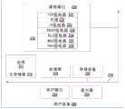
Fig. 1 is a block diagram illustrating an environment in which a user device communicates data with a remote host via a network node according to TCP, in accordance with various embodiments.
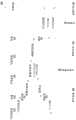
Fig. 2 is a block diagram illustrating a user equipment that adapts packets from TCP to a private protocol for transmission over a radio network, in accordance with various embodiments.
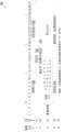
Fig. 3 is a block diagram illustrating a network node that adapts data to be transmitted between a private protocol and TCP, in accordance with various embodiments.
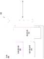
Fig. 4 is a block diagram illustrating a system that maintains TCP semantics (semantic) between a user device and a remote host while reducing TCP traffic between the user device and a network node, in accordance with various embodiments.
Fig. 5 is a sequence diagram illustrating a sequence of uplink data transmissions between a user equipment and a remote host according to TCP semantics, in accordance with various embodiments.
Fig. 6 is a block diagram illustrating a TCP header that may be implemented in TCP semantics, in accordance with various embodiments.
Fig. 7 is a block diagram illustrating a plurality of data packets that may be used to implement a private protocol between a user device and a network node, in accordance with various embodiments.
Fig. 8 is a block diagram illustrating an apparatus for receiving and transmitting data packets over a radio network, in accordance with various embodiments.
Fig. 9 is a flow diagram illustrating a method for providing acknowledgment data to TCP layer circuitry based on transmission of a plurality of data packets encapsulating data from a plurality of TCP packets, in accordance with various embodiments.
Fig. 10 is a flow diagram illustrating a method for providing data to TCP layer circuitry based on receipt of a plurality of data packets according to another protocol, in accordance with various embodiments.
Fig. 11 is a flow diagram illustrating a method for providing data received according to a private protocol to a remote host according to a TCP protocol, in accordance with various embodiments.
Fig. 12 is a flow diagram illustrating a method for transmitting a plurality of data packets adapted from TCP to another protocol to a user device, in accordance with various embodiments.
Detailed Description
In the following detailed description, reference is made to the accompanying drawings, which form a part hereof wherein like numerals designate like parts throughout, and in which is shown by way of illustration embodiments that may be practiced. It is to be understood that other embodiments may be utilized and structural or logical changes may be made without departing from the scope of the present disclosure. The following detailed description is, therefore, not to be taken in a limiting sense, and the scope of the embodiments is defined by the appended claims and their equivalents.
Various operations will be described as multiple discrete actions or operations in turn, in a manner that is most helpful in understanding the claimed subject matter. However, the order of description should not be construed as to imply that these operations are necessarily order dependent. In particular, these operations may not be performed in the order of presentation. The described operations may be performed in a different order than the described embodiments. Various additional operations may be performed and/or described operations may be omitted in further embodiments.
For the purposes of this disclosure, the phrases "a or B" and "a and/or B" mean (a), (B), or (a and B). For the purposes of this disclosure, the phrase "A, B and/or C" means (a), (B), (C), (a and B), (B and C), (a and C), or (A, B and C).
The description may use the phrases "in an embodiment" or "in embodiments," which each refer to one or more of the same or different embodiments. Furthermore, the terms "comprising," "including," "having," and the like, as used with respect to embodiments of the present disclosure, are synonymous.
As used herein, the term "module" and/or "logic" may refer to, be part of, or include: an application specific integrated circuit ("ASIC"), an electronic circuit, a processor (shared, dedicated, or group) and/or memory (shared, dedicated, or group) that executes one or more software or firmware programs, a combinational logic circuit, and/or other suitable hardware components that provide the described functionality.
Beginning first with fig. 1, a block diagram illustrates a block diagram of anenvironment 100 in which a user equipment ("UE") 110 communicates data with a remote host 150 via a network node 120 according to TCP, according to various embodiments. The UE110 may be any type of mobile computing device equipped with mobile broadband circuitry, such as a netbook, a tablet, a handheld computing device, an internet-enabled appliance, a gaming device, a mobile phone, a smartphone, an e-book reader, a personal data assistant, and so forth. UE110 may be any device suitable for communicating over a network (e.g., radio network 115) in accordance with, for example, one or more third generation partnership project ("3 GPP") specifications.
According to an embodiment, the UE110 may be configured for inter-system communication across theradio network 115.Radio network 115 may include a wireless cellular network, such as a global system for mobile communications ("GSM") network, a universal mobile telecommunications system ("UTMS"), and/or a code division multiple access ("CDMA") network. The wireless cellular network may comply with one or more standards, such as long term evolution ("LTE") or LTE-advanced ("LTE-a"), third generation ("3G"), fourth generation ("4G"), fifth generation ("5G"), worldwide interoperability for microwave access ("WiMAX") (e.g., mobile WiMAX), or other similar standards.
For communication over theradio network 115, the UE110 may operate on a cell. In some embodiments, the network node 120 may be adapted to provide such a cell, and thus, the network node 120 may be an access node, such as a node B or an evolved node B ("eNB") (macro eNB, pico eNB, femto eNB). In another embodiment, the network node 120 may be a gateway, such as a serving gateway ("S-GW"), a packet data network gateway ("P-GW"). In embodiments in which network node 120 is a gateway,radio network 115 and network node 120 may be coupled with a plurality of components (not shown) associated withcoupling radio network 115 to a core network that provides network node 120.
Through network node 120, UE110 may be adapted to communicate with remote hosts acrossinternet 130. Thus, remote host 150 may be any system suitable for providing resources (e.g., streaming content, web sites, etc.) over theinternet 130. To communicate via theinternet 130, the UE110 and the remote host 150 may use TCP (TCP/IP). Thus, data transmitted between UE110 and remote host 150 may be encapsulated into TCP packets. Because TCP is a reliable protocol, TCP packets may prompt for a TCP acknowledgement ("ACK") to determine successful delivery.
In the illustrated arrangement, TCP packets originating from UE110 and destined for remote host 150 may traverseradio network 115 to network node 120. Network node 120 may respond to TCP packets from UE110 with TCP ACKs and then transmit these TCP packets to remote host 150 overinternet 130. Network node 120 may similarly process and acknowledge TCP packets originating from remote host 150 and destined for UE 110. In practice, this communication approach may generate a large number of TCP ACKs between UE110 and network node 120. However, the architecture of UE110 and network node 120 may include reliable data transmission through the underlying circuitry that enables transmission of TCP packets.
In an embodiment, data transmitted between UE110 and network node 120 overradio network 115 may be reliably communicated through an automatic repeat request ("ARQ") mechanism implemented at the link layer of network node 120 and UE 110. For example, when a radio link control ("RLC") sublayer of the link layer operates in an acknowledged mode ("AM"), the RLC sublayer may send an ARQ ACK based on the received data. Alternatively, the medium access control ("MAC") sublayer of the link layer may send a hybrid ARQ ("HARQ") ACK when the RCL sublayer operates in unacknowledged mode ("UM").
It should be understood that the layer/sublayer circuitry may be dedicated circuitry configured to implement only operations associated with that particular layer/sublayer or may be shared circuitry configured to implement operations associated with more than one layer/sublayer.
Based on the reliable data transmission mechanism provided by the link layer circuitry of network node 120 and UE110, the TCP layer circuitry may be provided with TCP ACKs for TCP packets without actually sending TCP ACKs overradio network 115. According to an embodiment, TCP packets to be transmitted between UE110 and network node 120 may be intercepted before transmission overradio network 115. The payload data from the TCP packet may be encapsulated according to a private protocol that may be tunneled in for use in a communication user datagram protocol ("UDP") between the UE110 and the network node 120. Data from the TCP layer circuitry may then be transmitted between UE110 and network node 120 based on a private protocol, which may not require its own acknowledgement data to be transmitted overradio network 115. UE110 and network node 120 may then locally generate a TCP ACK based on the ARQ ACK from the respective link layer circuitry.
At the UE110, data received according to the private protocol may be locally adapted as TCP packets and provided to TCP layer circuitry, such that the TCP layer circuitry may be agnostic to the transport mechanisms implemented at the lower layer circuitry while still maintaining reliable data transmission. Similarly, network node 120 may adapt data received according to a private protocol to a TCP packet before being transmitted over theinternet 130 to remote host 150. In this way, TCP ACKs transmitted overradio network 115 may be reduced while TCP semantics between UE110 and remote host 150 are still maintained.
With respect to fig. 2, a block diagram illustrates a UE 200 that adapts packets from TCP to a private protocol for transmission over a radio network, in accordance with various embodiments. UE 200 may be any UE suitable for communicating on a radio network, such as UE110 of fig. 1. The UE 200 may include, but is not limited to, a main memory 210, aprocessor 218, a storage device 220, auser interface 222, adisplay 224, and a communication interface 230. One or more of these components may be communicatively coupled via abus 219. Thebus 219 may be any subsystem suitable for communicating data within the UE 200. Thebus 219 may include multiple computer buses and additional circuitry suitable for transferring data.
As a way of receiving data, the UE 200 may include auser interface 222 to receive input from a user. According to different embodiments, theuser interface 222 may allow the user to interact with the UE 200 in a variety of ways — for example, theuser interface 222 may be presented to the user on thedisplay 224 as a graphical user interface or through a command line interface. To receive user input, theuser interface 222 may be implemented as hardware, software, or a combination of both and may include or be communicatively coupled to one or more hardware devices (e.g., keyboard, mouse, touch screen, or gesture recognition) adapted for user input. Further, theprocessor 218 may execute some or all of the instructions for theuser interface 222.
Coupled to theprocessor 218 is a main memory 210. The main memory 210 may provide both short-term and long-term storage, and may in fact be divided into several units, including a unit located at theprocessor 218. The main memory 210 may be volatile, such as static random access memory ("SRAM") and/or dynamic random access memory ("DRAM"), and may provide storage (at least temporarily) of computer-readable instructions, data structures, software applications, and other data for the UE 200. Such data may be loaded from storage device 220 and/or communication interface 230. The main memory 210 may also include cache memory, such as a cache memory located at theprocessor 218. The main memory 210 may include, but is not limited to, instructions related to theapplication 211 to be executed by theprocessor 218. Theapplication 211 may be any application associated with communicating with a resource on the internet. For example, theapplication 211 may be a web browser application, a voice over IP ("VoIP") application, a file sharing application, a messaging application (e.g., a mail application, an instant messaging application, etc.), a social media application, a media application (e.g., an application suitable for streaming audio and/or video), and so forth.
According to some embodiments, theapplication 211 may cause the communication interface 230 to transmit data to or from a remote host accessible over the internet. Data communicated to or from theapplication 211 is processed at the IP layer circuitry 233 based on communications over the internet. However, theapplication 211 may first generate data to be processed at the TCP layer circuitry 231 for reliable communication over the internet. TCP layer circuitry 231 may packetize data received fromapplication 211. The UE 200 cannot be directly connected to the internet, but may rely on a network node to relay TCP packets associated with theapplication 211 over the radio network.
To reduce TCP traffic on the radio network, an agent 232 may be implemented, for example, at the communication interface 230 between the TCP layer circuitry 231 and the IP layer circuitry 233. Although the agent 232 is shown within the communication interface 230, the agent 232 may be hardware, software, firmware, and/or a combination thereof. For example, the agent 232 may be included in an ASIC or other integrated circuit. In many embodiments, instructions associated with the agent 232 are executed by theprocessor 218, and thus, instructions associated with the agent 232 may be stored (at least temporarily) in the main memory 210. In various embodiments, the agent 232 may be implemented at least in part in circuitry (e.g., processing circuitry, processor circuitry, logic circuitry, etc.) of the UE 200. Thus, for example, the agent circuitry may include circuitry configured to perform various operations described for the agent 232.
In various embodiments, the agent 232 may be adapted to implement a private protocol between the UE 200 and the network node. The private protocol may feature connection-oriented data flow support so that the TCP layer circuitry 231 andapplications 211 may operate without extensive adaptation to standard configurations-e.g., TCP semantics between the UE 200 and a remote host providing resources to the UE 200 may be maintained. In various embodiments, the private protocol may be tunneled into another transport layer protocol than TCP (e.g., a protocol that does not require reliability, guaranteed delivery, copy protection, and/or initial connection establishment). In one embodiment, the private protocol may be tunneled into the UDP.
To establish a TCP connection, agent 232 may be adapted to process a TCP synchronization packet ("SYN") that may be received from TCP layer circuitry 231. Agent 232 may intercept the TCP SYN and identify a source port value and a destination port value from the TCP SYN. The agent 232 may then apply a hash function to the source port value and the destination port value to generate a hash value. The hash value may then be inserted into the data packet according to the private protocol (e.g., into a header of the private protocol data packet). The hash value may occupy fewer bytes than the source and destination port values so that the data packet itself consumes less resources when transmitted over the radio network to the network node-for example, the source port value may be two bytes and the destination port value may be two bytes, whereas the hash value itself calculated from the source and destination port values may only require two bytes. The agent 232 may include or may be communicatively coupled to a lookup table that maps hash values to source port values and destination port values.
To maintain TCP semantics between the UE 200 and the remote host, the agent 232 may cause the data packet to be transmitted to a network node that includes a source port value and a destination port value, and a predetermined value that indicates that the data packet is to be used to maintain TCP semantics (e.g., the network node may be adapted to apply the same hash function to the source port value and the destination port value and maintain a lookup table that maps hash values to the source port value and the destination port value). Similarly, the agent 232 may be adapted to process data packets from a network node that includes source and destination port values and a predetermined value that indicates that the data packet is to be used to maintain TCP semantics between the remote host and the UE 200.
In the uplink direction (e.g., from the UE 200 to the remote host), the agent 232 may be adapted to intercept TCP packets generated at the TCP layer circuitry 231. For each TCP packet, the agent 232 may extract the payload data and insert the payload data into the data packet according to the private protocol. In addition, the agent 232 may identify a source port value, a destination port value, and a TCP sequence number ("SN") from the header of the TCP packet. The agent 232 may then determine a hash value associated with the source port value and the destination port value, for example, by accessing a lookup table that maps the source port value and the destination port value to hash values, or by applying a hash function to the source port value and the destination port value. The agent 232 may then provide the data packet to the lower layer circuitry 233 and 238 to be transmitted to the remote host.
The lower layer circuitry 233-. The IP layer circuitry 233 may be communicatively coupled to packet data convergence protocol ("PDCP") layer circuitry 234. The PDCP layer circuitry 234 may be associated with, for example, user plane and interface control over the radio network. In addition, the PDCP layer circuitry 234 may perform compression and decompression on the IP headers. The PDCP layer circuitry 234 may be communicatively coupled to linklayer circuitry 235. In various embodiments,link layer circuitry 235 may include at least two sublayers: radio link control ("RLC") layer circuitry 236 and medium access control ("MAC") layer circuitry 237. The RLC layer circuitry 236 may provide, for example, concatenation, segmentation and/or reassembly of data units (e.g., protocol data units and/or service data units), continuous delivery of data units, duplication detection, error recovery, etc. to communicate with a network node over a radio network. MAC layer circuitry 237 may provide addressing and channel access mechanisms and interface with physical ("PHY") layer circuitry 238. Thelink layer circuitry 235 may be communicatively coupled to PHY layer circuitry 238, which may include hardware circuitry for transmitting data over a radio network. In various embodiments, the PHY layer circuitry 238 may include one or more network adapters and/or circuitry for data transmission over one or more radio networks (e.g., Wi-Fi networks, cellular data networks, etc.).
Thelink layer circuitry 235 may provide ARQ mechanisms-e.g., the RLC layer circuitry 236 may process ARQ data when operating in AM and the MAC layer circuitry 237 may process HARQ data when operating in UM. In various embodiments, the agent 232 may be adapted to utilize ARQ data from thelink layer circuitry 235 to locally generate TCP ACK data for the TCP layer circuitry 231. For TCP packets having payload data, the agent 232 may identify the TCP SN from the header of the TCP packet. When the agent 232 encapsulates payload data from a TCP packet into the lower layer circuitry 233-. For example, the agent 232 may interact with the PDCP layer circuitry 234 to obtain a PDU SN associated with the data packet at thelink layer circuitry 235, which the agent 232 may then map to an initial TCP SN. When thelink layer circuitry 235 causes the PHY layer circuitry 238 to transmit a data packet over the radio network, thelink layer circuitry 235 may receive ARQ data associated with the data packet. The agent 232 may communicate with thelink layer circuitry 235, either directly or through the PDCP layer circuitry 234, to determine whether the ARQ data indicates that the data packet has been successfully transmitted to the network node. The agent 232 may access the lookup table based on the PDU indicated by the ARQ data as successfully transmitted to the network node and locally generate a TCP ACK for the TCP SN corresponding to the PDU SN based on the ARQ data. The agent 232 may provide the locally generated TCP ACK to the TCP layer circuitry 231 such that reliable TCP data communications may be maintained and the TCP layer circuitry 231 (and, by association, the application 211) may operate independently of the private protocol implemented by the agent 232 to reduce TCP traffic through the radio network.
In the downlink direction (e.g., from the remote host to the UE 200), the agent 232 may be adapted to receive private-protocol data packets from the underlying circuitry 233 and 238. For each private-protocol data packet, the agent 232 may extract the payload data and insert the payload data into the TCP packet according to TCP. Further, the agent 232 may identify a hash value from a private-protocol data packet (e.g., from a header of the data packet) and determine a source port value and a destination port value from the hash value. The agent 232 may insert the source port value and the destination port value into the header of the TCP packet and provide the TCP packet to the TCP layer circuitry 231. TCP layer circuitry 231 may then process the TCP packets from the agent according to the TCP semantics, for example by providing payload data toapplication 211.
To terminate the TCP connection, private-protocol data packets may be transmitted between the agent 232 and the network node. Such private-protocol data packets may be used as TCP connection termination messages ("FIN") for the TCP layer circuitry 231. In various embodiments, the private-protocol data packet may include a hash value that is based on the source port value and the destination port value of the TCP connection, but may not have payload data. In the uplink direction, the agent 232 may be adapted to generate such private-protocol data packets based on the TCP FIN received from the TCP layer circuitry 231. In the downlink direction, the agent 232 may be adapted to generate a TCP FIN for the TCP layer circuitry 231 based on such private protocol data packets.
With respect to fig. 3, a block diagram illustrates a network node 300 that adapts data to be transmitted between a private protocol and TCP, in accordance with various embodiments. Network node 300 may be any server suitable for facilitating communication between a UE and a remote node over the internet, e.g., network node 120 of fig. 1. Network node 300 may include, but is not limited to, aprocessor 318, a storage device 320, amain memory 310, and a communication interface 330. These components may be communicatively coupled via abus 319.Bus 319 may be any subsystem adapted to transfer data within network node 300.Bus 319 may include multiple computer buses and other circuitry suitable for communicating data.
Coupled to theprocessor 318 ismain memory 310. Themain memory 310 may provide both short-term and long-term storage, and may in fact be divided into several units, including a unit located at theprocessor 318. Themain memory 310 may also include a cache memory, such as a cache memory located at theprocessor 318.Main memory 310 may be volatile, such as SRAM and/or DRAM, and may provide storage (at least temporarily) for computer-readable instructions, data structures, software applications, and other data for network node 300. Such data may be loaded from storage device 320, which storage device 320 may be, for example, one or more hard disk drives, solid state drives, compact disks and drives, digital versatile disks and drives, and the like.
According to an embodiment, the network node 300 may be adapted for communicating with UEs over a radio network or with remote devices over the internet. To facilitate such communication, network node 300 may include a communication interface 330. Communication interface 330 may allow network node 300 to relay data between the UE and the remote host.
In connection with a proxy implemented at the UE, the network node 300 may include a proxy 332, e.g., between the TCP layer circuitry 331 and the IP layer circuitry 333, on behalf (proxy) 332. Although the representation 332 is shown within the communication interface 330, the representation 332 may be hardware, software, firmware, and/or a combination thereof. For example, the proxy 332 may be included in an ASIC or other integrated circuit. In many embodiments, the instructions associated with the representative 332 are executed by theprocessor 318, and thus the instructions associated with the representative 332 may be stored (at least temporarily) in themain memory 310. In various embodiments, the representation 332 may be implemented at least in part in circuitry (e.g., processing circuitry, processor circuitry, logic circuitry, etc.) of the network node 300. Thus, for example, the delegate circuitry may comprise circuitry configured to perform various operations described for the delegate 332.
In various embodiments, the proxy 332 may be adapted to implement a private protocol between the UE and the network node 300. The private protocol may allow the TCP layer circuitry of the remote host and the UE to maintain TCP semantics while reducing TCP traffic on the radio network between the network node 300 and the UE. In various embodiments, the private protocol may be tunneled, for example, into UDP.
To establish a TCP connection, the proxy 332 may be adapted to process packets indicating the TCP connection to be established, which may be received from the UE or a remote host. In one embodiment, the proxy 332 may receive a data packet according to a private protocol that includes source and destination port values and a predetermined value that indicates the data packet to be used to maintain TCP semantics between the UE and the remote host. The proxy 332 may be adapted to apply a hash function to the source and destination port values and maintain a lookup table that maps hash values to the source and destination port values. The TCP SYN may be transmitted to the remote host to establish a TCP connection at the endpoint.
Similarly, delegate 332 may intercept the TCP SYN (including the source port value and the destination port value) from the remote host to establish a TCP connection with the UE. The proxy 332 may then apply a hash function to the source port value and the destination port value from TCP PYN to generate a hash value. The proxy 332 may generate a data packet according to the private protocol that includes the source and destination port values from TCP PYN and a predetermined value indicating the data packet to be used to maintain TCP semantics (e.g., the UE may be adapted to apply the same hash function to the source and destination port values and maintain a lookup table that maps the hash value to the source and destination port values). Accordingly, the respective TCP layer circuitry at the UE and the remote host may operate in accordance with TCP connections with respective endpoints established at the UE and the remote host.
In the downlink direction (e.g., from the remote host to the UE), the proxy 332 may be adapted to intercept TCP packets received from the remote host at the TCP layer circuitry 331 and to be relayed to the UE. For each TCP packet, the proxy 332 may extract the payload data and insert the payload data into the data packet according to the private protocol. Further, delegate 332 may identify a source port value, a destination port value, and/or a TCP SN from a header of a TCP packet. The proxy 332 may then determine a hash value associated with the source port value and the destination port value, for example, by accessing a lookup table that maps the source port value and the destination port value to hash values, or by applying a hash function to the source port value and the destination port value. The representative 332 may then provide the data packet to the lower layer circuitry 333 and 338 to be transmitted to the remote host.
In the uplink direction (e.g., from the UE to the remote host), the proxy 332 may be adapted to receive private-protocol data packets from the lower layer circuitry 333 and 338. For each private-protocol data packet, the proxy 332 may extract the payload data and insert the payload data into the data packet according to TCP. Further, delegate 332 may identify a hash value from the private-protocol packet (e.g., from a header of a TCP packet) and determine a source port value and a destination port value from the hash value, e.g., by accessing a lookup table. The proxy 332 may insert the source port value and the destination port value into the header of the TCP packet and provide the TCP packet to the TCP layer circuitry 331. The TCP layer circuitry 331 may then process the TCP packets from the proxy according to TCP semantics, for example, by providing the TCP packets to lower layer circuitry 333 and 338 for transmission to the remote host.
The lower layer circuitry 333 and 338 may include IP layer circuitry 333 adapted to communicate data based on IP addresses. To communicate with the UE over the radio network, the IP layer circuitry 333 may be communicatively coupled to the PDCP layer circuitry 334. The PDCP layer circuitry 334 may perform, among other operations, compression and decompression of IP headers. The PDCP layer circuitry 334 can be communicatively coupled to thelink layer circuitry 335. In various embodiments, thelink layer circuitry 335 may include at least two sublayers: RLC layer circuitry 336 and MAC layer circuitry 337. The RLC layer circuitry 336 may provide, for example, concatenation, segmentation and/or reassembly of data units (e.g., protocol data units and/or service data units), continuous transmission of data units, duplication detection, error recovery, etc. to communicate with UEs over a radio network. MAC layer circuitry 337 may provide addressing and channel access mechanisms and interface with PHY layer circuitry 338. Thelink layer circuitry 335 may be communicatively coupled to the PHY layer circuitry 338, and the PHY layer circuitry 338 may include hardware circuitry for transmitting data to the UE over a radio network and to a remote host over the internet. In various embodiments, PHY layer circuitry 338 may include one or more network adapters, modems, and or circuits for data communication over one or more networks.
With respect to communication with the UE,link layer circuitry 335 may implement an ARQ mechanism-e.g., RLC layer circuitry 336 may transmit ARQ data and/or MAC layer circuitry 337 may transmit HARQ data. For each private-protocol data packet received at thelink layer circuitry 335, thelink layer circuitry 335 may transmit an ARQ ACK and/or HARQ ACK to the UE, which may be utilized by the UE to locally generate a TCP ACK.
When proxy 332 adapts a TCP packet from at TCP layer circuitry 331, proxy 332 may be adapted to utilize ARQ data fromlink layer circuitry 335 to locally generate a TCP ACK for TCP layer circuitry 331. For each TCP packet having payload data, the proxy 332 encapsulates 338 the payload data from the TCP packet to the underlying circuitry 333, and the proxy 332 may map the PDU SN to the TCP SN, e.g., by updating a lookup table. For example, the proxy 332 may interact with the PDCP layer circuitry 334 to obtain a PDU SN associated with the data packet at thelink layer circuitry 335, and then the proxy 332 may map the PDU SN to the initial TCP SN. When thelink layer circuitry 335 causes the PHY layer circuitry 338 to transmit a data packet to the UE over the radio network, thelink layer circuitry 335 may receive ARQ data associated with the data packet. The proxy 332 may communicate with thelink layer circuitry 335, either directly or through the PDCP layer circuitry 334, to determine whether the ARQ data indicates that the data packet has been successfully transmitted to the UE. The proxy 332 may access the lookup table based on the PDU indicated by the ARQ data as successfully transmitted to the UE and locally generate a TCP ACK for the TCP SN corresponding to the PDU SN based on the ARQ data. Delegate 332 may provide the locally generated TCP ACK to TCP layer circuitry 331 such that reliable TCP data communication may be maintained and TCP layer circuitry 331 may operate independently of the private protocol implemented by delegate 332 to reduce TCP traffic on the radio network.
With respect to communication with a remote host, the proxy 332 may implement a cache or may be communicatively coupled to a cache, such as a cache at themain memory 310. The proxy 332 may buffer payload data in the UE's data packets. Such a buffering mechanism may allow delegate 332 to resend data received from the UE to the remote host when a TCP ACK is not received from the remote host, without requiring the UE to resend data that is not acknowledged as received by the remote host.
To terminate the TCP connection, private-protocol data packets may be transmitted between the delegate 332 and the UE and between them. Such private-protocol data packets may be used as TCP FIN for TCP layer circuitry 331. In various embodiments, the private-protocol data packet may include a hash value based on the source port value and the destination port value of the TCP connection, but may not have payload data. In the downlink direction, the proxy 332 may be adapted to generate private-protocol data packets based on TCP FIN received from the TCP layer circuitry 331 (e.g., TCP FIN originating from a remote host). In the uplink direction, the proxy 332 may be adapted to generate a TCP FIN (e.g., to be transmitted to the remote host) for the TCP layer circuitry 331 based on such private-protocol data packets received from the UE.
According to various embodiments, the network node 300 may be adapted to provide a radio cell on which the UE operates. However, such a cell may have a limited coverage and, thus, the network node 300 may be adapted to handover the UE to another network node adapted to provide the UE with another cell. In such embodiments, the proxy 332 may be adapted to transmit a mapping table (e.g., a mapping table that maps hash values to source port values and destination port values) to another network node based on a handover of the UE to the other network node.
Referring to fig. 4, a block diagram illustrates asystem 400 that maintainsTCP semantics 480 between a UE405 and a remote host 470 while having reduced TCP traffic between the UE405 and a network node 440. FIG. 4 may illustrate an embodiment of theenvironment 100 shown in FIG. 1. Accordingly, UE405 may be an embodiment of UE110, network node 440 may be an embodiment of network node 120, and/or remote host 470 may be an embodiment of remote host 150 of fig. 1.
In an embodiment, an application 410 executed by the UE405 may wish to reliably communicate with an application 472 executed by a remote host 470. The application 472 at the remote host 470 may access the application 410 at the UE405 through the internet, and thus, the UE405 and the remote host 470 may utilize TCP/IP. Accordingly, the respective TCP layer circuitry 412, 474 at the UE405 and the remote host 470 may communicate according toTCP semantics 480.
Data to be transmitted between the UE405 and the remote host 470 may pass through the network node 440. However, such an arrangement may result in a large amount of TCP ACK data being transmitted between the UE405 and the network node 440, which in effect repeats the ARQ and/or HARQ mechanisms implemented by the RLC layer circuitry 424, 454 and MAC layer circuitry 426, 456, respectively. That is, the TCP ACK mechanism of the TCP layer circuitry 412, 442 may not be necessary because the ARQ and/or HARQ mechanisms already provide reliable data communication at the link layer circuitry 424, 426, 454, 456. Thus, ARQ and/or HARQ mechanisms may be used at the UE405 and the network node 440 to locally generate TCP ACKs without requiring TCP ACK data to be transmitted over the air between the UE405 and the network node 440.
In the uplink direction (e.g., data from the UE405 to the remote node 470), the application 410 may provide the data to the TCP layer circuitry 412. The TCP layer circuitry 412 may be adapted to generate a plurality ofTCP packets 414 based on the data. However, proxy 416 may be adapted to interceptTCP packet 414 whenTCP packet 414 is provided to lower layer circuitry 420-428. The proxy 416 may be adapted to communicate with a delegate 446 at the network node 440 according to aprivate protocol 484.
In various embodiments, theproprietary protocol 484 may be a system of digital rules for exchanging data. Agents 416 and representatives 446 may be adapted to receive, process, and/or intercept data received according to such digital rules. The other layer circuits 412, 420, 428, 442, 450, 458 may not be suitable for transferring data according to theprivate protocol 484.
According to various embodiments, proxy 416 may encapsulate payload data frommultiple TCP packets 414 into data packets according toprivate protocol 484. To identify the source and destination endpoints associated with each TCP packet, proxy 416 may be adapted to identify a source port value and a destination port value from the TCP packet. The agent may apply a hash function to the source port value and the destination port value to generate a hash value and store the hash value in a table that associates the hash value with the source port value and the destination port value.
To keep TCP layer circuitry 412 independent ofprivate protocol 484, proxy 416 may identify the TCP SN from the respective header of therespective TCP packet 414 provided to proxy 416. When the proxy 416 provides the private-protocol data packets 418 to the lower layer circuitry 420-428, the proxy 416 may associate each TCP SN with a PDU from the lower layer circuitry 420-428. At the RLC layer circuitry 424, each data packet may be associated with an RLC PDU. Similarly, each data packet may be associated with a MAC PDU at the MAC layer circuitry 426. The proxy 416 may be adapted to receive RLC PDUs and/or MAC PDUs and associate a TCP SN with at least one of the RLC PDUs or MAC PDUs (e.g., the proxy 416 may store the TCP SN and the PDUs in a table that maps TCP SNs to the PDUs).
The link layer circuitry 424, 426 may provide the private-protocol data packet to the PHY layer circuitry 428, and the PHY layer circuitry 428 may then transmit the private-protocol data packet to the network node 440. The link layer circuitry 454, 456 may receive these private-protocol data packets from the PHY layer circuitry 458 of the network node 440. When a data packet is received at the link layer circuitry 454, 456, the link layer circuitry 454, 456 may cause ARQ and/or HARQ ACK data to be sent to the UE 405. When the link layer link 424, 426 of the UE405 receives ARQ and/or HARQ ACK data, the proxy 416 may be adapted to determine from the ARQ and/or HARQ ACK data whether each data packet has been successfully transmitted to the network node 440.
In embodiments where the RLC layer circuitry 424 operates in AM mode, the RLC layer circuitry 424 may provideARQ data 430 to the proxy 416. The proxy 416 may identify an acknowledgement from theARQ data 430 that the data packet corresponding to the RLC PDU has been successfully transmitted to the network node 440. In embodiments where the RLC layer circuitry 424 operates in UM mode, the MAC layer circuitry 426 may provideHARQ data 432 to the proxy 416. The proxy 416 may identify an acknowledgement from theHARQ data 432 that the data packet corresponding to the MAC PUD has been successfully transmitted to the network node 440. The proxy 416 may then identify the TCP SN based on the PDU, such as by accessing a lookup table with the PDU, and locally generate a TCP ack for the identified TCP SN. Proxy 416 may provide locally generated TCP ACKs to TCP layer circuitry 412 so that TCP layer circuitry 412 may provide reliable data communication for application 410.
At network node 440, a private-protocol data packet 448 may arrive at delegate 446 from lower layer circuitry 450-458. For each private-protocol data packet, the delegate 446 may extract payload data and insert the payload data into a TCP packet to maintainTCP semantics 480. The delegate 446 may identify a hash value from the private-protocol packet (e.g., from a header of a TCP packet) and determine a source port value and a destination port value from the hash value, e.g., by accessing a lookup table. The proxy 446 may insert the source port value and the destination port value into the header of the TCP packet and provide the TCP packet to the TCP layer circuitry 442. The TCP layer circuitry 442 may then provide the TCP packets to the IP layer circuitry 450. The IP layer circuitry 450 may cause TCP packets to be transmitted over the internet to the IP layer circuitry 476 of the remote host in accordance withIP 486.
In the downlink direction (e.g., from the remote host 470 to the UE 405), the application 472 may provide data to the TCP layer circuitry 474 to be transmitted to the UE405 according to theTCP semantics 480. The TCP layer circuitry 474 may packetize the application data and provide the TCP packets to IP layer circuitry 476, which transmits the TCP packets to the network node 440 in accordance withIP 486. At the network node 440, the TCP packets may arrive at the TCP layer circuitry 442 and the delegate 446 may intercept theseTCP packets 444 to be transmitted to the UE 405. For each TCP packet, delegate 446 may extract payload data and insert the payload data into the data packet according toprivate protocol 484. Further, delegate 446 can identify a source port value, a destination port value, and/or a TCP SN from a header of a TCP packet. The proxy 446 may then determine a hash value associated with the source port value and the destination port value, for example, by accessing a lookup table that maps the source port value and the destination port value to hash values or by applying a hash function to the source port value and the destination port value. The representative 446 may then provide the data packet as part of a plurality of private-protocol data packets 448 to lower layer circuitry 450-458 for transmission to the UE 405.
In adapting the plurality ofTCP packets 444 into the plurality ofdata packets 448, the delegate 446 may identify a TCP SN from respective headers ofrespective TCP packets 444 provided to the delegate 446. When the representative 446 provides the privateprotocol data packets 448 to the lower layer circuitry 450- > 458, the representative 446 may associate each TCP SN with a PDU from the lower layer circuitry 450- > 458. At the RLC layer circuitry 454, each data packet may be associated with an RLC PDU. Similarly, each data packet may be associated with a MAC PDU at MAC layer circuitry 456. The delegate 446 may be adapted to receive the RLC PDU and/or the MAC PDU and associate the TCP SN with at least one of the RLC PDU or the MAC PDU (e.g., the delegate 446 may store the TCP SN and the PDU in a table that maps the TCPSN to the PDU).
The link layer circuitry 454, 456 may provide the private-protocol data packets to the PHY layer circuitry 458, and the PHY layer circuitry 458 may then transmit the private-protocol data packets to the UE 405. The link layer circuitry 424, 426 may receive these private protocol data packets from the PHY layer circuitry 428 of the UE 405. When a data packet is received at the link layer circuitry 424, 426, the link layer circuitry 424, 426 may cause ARQ and/or HARQ ACK data to be sent to the network node 440. When the link layer link 454, 456 of the network node 440 receives ARQ and/or HARQ ACK data, the delegate 446 may be adapted to determine from the ARQ and/or HARQ ACK data whether each data packet has been successfully transmitted to the UE 405.
In embodiments where RLC layer circuitry 454 operates in AM mode, RLC layer circuitry 454 may provideARQ data 460 to delegate 446. The delegate 446 may identify from theARQ data 460 an acknowledgement that the data packet corresponding to the RLC PDU has been successfully transmitted to the UE 405. In embodiments where the RLC layer circuitry operates in UM mode, the MAC layer circuitry 456 may provideHARQ data 462 to the delegate 446. The proxy 446 may identify an acknowledgement from theHARQ data 462 that the data packet corresponding to the MAC PDU has been successfully transmitted to the UE 405. Representative 446 may then identify the TCP SN based on the PDU, such as by accessing a lookup table with the PDU, and locally generate a TCP ACK for the identified TCP SN. The delegate 446 may provide locally generated TCP ACKs to the TCP layer circuitry 442 so that the TCP layer circuitry 442 may provide reliable data communications.
At the UE405, the proxy 416 may be adapted to receive private protocol data packets from the lower layer circuitry 420 and 428. For each private-protocol data packet 418, proxy 416 may extract the payload data and insert the payload data into a TCP packet according to TCP. Further, the proxy 416 may identify a hash value from the private-protocol packet (e.g., from the header of a TCP packet) and determine a source port value and a destination port value from the hash value, e.g., by accessing a lookup table. Proxy 416 may insert the source port value and the destination port value into the header of the TCP packet and provide the TCP packet included in plurality ofTCP packets 414 into TCP layer circuitry 412. The TCP layer circuitry 412 may then process the TCP packets according to theTCP semantics 480 maintained between the TCP layer circuitry 412 of the UE405 and the TCP layer circuitry 474 of the remote host 470.
With respect to fig. 5, the sequence illustrates asequence 500 of uplink data transmissions between a UE 505 and a remote host 530 according to TCP semantics, in accordance with various embodiments. Fig. 5 may illustrate an embodiment of a sequence of data communications in theenvironment 100 shown in fig. 1. Accordingly, UE 505 may be an embodiment of UE110, network node 520 may be an embodiment of network node 120, and/or remote host 530 may be an embodiment of remote host 150 of fig. 1.
First,TCP layer circuitry 510 of UE 505 may provide TCP packets to be transmitted to remote host 530 to proxy 512 (operation 552). Theagent 512 may extract a source port value, a destination port value, and a TCP SN from the header of the TCP packet. Theproxy 512 may store the TCP SN in a table that associates the TCP SN with a PDU SN from the underlying circuitry 514 (operation 554). The proxy may adapt the TCP packet to a private protocol data packet and provide the private protocol data packet to the lower layer circuitry 514 (operation 556).Lower layer circuitry 514 of UE 505 may transmit the data packet tolower layer circuitry 522 of network node 520 through radio network 540 (operation 558).
Thelower layer circuitry 522 of network node 520 may provide the private-protocol data packet to delegate 524 (operation 560). To confirm that the private-protocol data packet has been successfully received at the network node 520, thelower layer circuitry 522 may send an ARQ ACK to the UE 505 (operation 562). In various embodiments, the ARQ ACK may be an ARQ ACK from RLC sublayer circuitry oflower layer circuitry 522 or a HARQ ACK from MAC sublayer circuitry oflower layer circuitry 522. Delegate 524 may adapt the private-protocol data packet to a TCP packet and buffer payload data from the private-protocol data packet (operation 564). The proxy 524 may then cause the TCP packets to be transmitted over the internet 542 to the circuitry 532 of the remote host 530 (operation 566). Based on the TCP packet, circuitry 532 of remote host 530 may cause a TCP ACK to be transmitted to network node 520 over internet 542 (operation 568). In the event that a TCP ACK or TCP ACK indication error is not received for the transmitted TCP packet, delegate 524 may cause payload data from the private-protocol data packet to be retransmitted (operation 570).
At the UE 505, an ARQ ACK for a data packet is received at the lower layer circuitry 514 (e.g., an ARQ ACK is received at the RLC sublayer circuitry or a HARQ ACK is received at the MAC sublayer circuitry). Based on the ARQ ACK, thelower layer circuitry 514 may notify theproxy 512 that the private-protocol data packet has been indicated as received at the network node 520 (operation 572). The notification may include a PDU SN associated with thelower layer circuitry 514, and theagent 512 may utilize the PDU SN to determine a corresponding TCP SN based on a table in which the TCP SN is associated with the PDU SN (operation 574).Agent 512 may then locally generate a TCP ACK that includes the TCP SN determined from the table lookup and provide the TCP ACK to TCP layer circuitry 510 (operation 576). In this way, traffic through radio network 540 may be reduced, for example, by reducing the transmission of TCP ACK data.
Turning to fig. 6, a block diagram illustrates aTCP header 600 that may be implemented in TCP semantics, in accordance with various embodiments.TCP header 600 may be generated locally and transmitted between circuitry of a computing device (e.g., UE110 and/or network node 120 of fig. 1). In addition,TCP header 600 may be transmitted over the internet between a network node and a remote host, such as network node 120 and remote host 150 of fig. 1.
According to an embodiment, the TCP header includes a source port field 605 and a destination port field 610. Source port field 605 and destination port field 610 may be respective communication endpoints at the UE and/or remote host, depending on whether the TCP header is transmitted in the uplink or downlink direction. The SN field 615 may include the SN of the first data octet in the TCP segment associated with the TCP header 600 (except when the SYN indication is present). The SN may be a starting SN if the SYN indication is present in the SN field 615.ACK field 620 may include the value of the next SN for an endpoint (e.g., a UE or a remote host) in anticipation of an acknowledgement that a TCP packet has been successfully received. The checksum field 625 may include a value calculated for error detection.
For transmission over a radio network between the UE and the network node, TCP acknowledgement and congestion control mechanisms may be implemented by ARQ mechanisms, and the value from the TCP SN field 615 may be mapped to the PDU SN from the RLC and/or MAC circuitry. The proprietary protocol described herein may be utilized in place of TCP. Furthermore, some fields of theTCP header 600 may be cleared and/or implemented locally so that no changes to the TCP circuitry are required. For example, the value for the checksum field 625 may be calculated locally.
Referring to fig. 7, a block diagram illustrates a plurality ofdata packets data packets radio network 115 of fig. 1).
To establish a TCP connection, a TCP SYN may be used. According to embodiments of the private protocol, the TCP SYN may be implemented in the private protocol usingdata packet 700. The private-protocol data packet 700 may include an indication for the connection establishment 705-for example, the connection establishment indication 705 may be a zero value of two bytes. To establish a TCP connection locally at a TCP layer circuit, private-protocol data packet 700 may include a source port value 710 and a destination port value 715. The proxy and/or delegate may then apply a hash function to the source port value 710 and the destination port value 715 to generate a hash value for implementing the private protocol. The proxy and/or delegate may include or be communicatively coupled to a respective lookup table that maps hash values to source port values and destination port values. The hash value may occupy fewer bytes than the source port value 710 and the destination port value 715, such that thesecond data packet 720 with payload data consumes less resources when transmitted over the radio network to the network node — for example, the source port value 710 may be two bytes and the destination port value 715 may be two bytes, but the hash value itself calculated from the source port value 710 and the destination port value may only require two bytes.
Hash value 725 may then be inserted into the data packet according to the private protocol, as shown by second privateprotocol data packet 720. Second private-protocol data packet 720 may include payload data 730. Payload data 730 may be extracted locally from the TCP packet. The second private-protocol data packet 720 may be transmitted between the UE and the network node to reduce TCP traffic on the radio network.
To close the TCP connection, private-protocol data packet 740 includes hash value 745 corresponding to source port value 710 and destination port value 715. However, such private-protocol data packet 740 may not have payload data, and the absence of payload data may indicate that such private-protocol data packet is to implement a TCP FIN for the TCP layer circuitry.
With respect to fig. 8, a block diagram illustrates anapparatus 800 for wireless reception and transmission of data between computing systems, in accordance with various embodiments.Device 800 may be, or may be included in, a UE or a network node (e.g., UE110 and/or network node 120 of fig. 1). In various embodiments, the circuitry of the apparatus may be integrated with and/or communicatively coupled to a communication interface (e.g., communication interface 230 of UE 200 shown in fig. 2, and/or communication interface 330 of network node 300 shown in fig. 3).Device 800 may include, but is not limited to,transmitter circuitry 805,receiver circuitry 810,communication circuitry 815, and/or one ormore antennas 820 coupled to at least each of the illustrated devices.
Briefly, thecommunication circuit 815 may be coupled to anantenna 820 to facilitate over-the-air transmission of signals to and from thedevice 800. The operations of thecommunication circuit 815 may include, but are not limited to, filtering, amplifying, storing, modulating, demodulating, converting, and the like.
Thetransmitter circuit 805 may be configured to receive a signal for transmission by thecommunication circuit 815. In some embodiments, thetransmitter circuit 805 may be adapted to generate a signal. Further, thetransmitter circuitry 805 may be adapted to scramble, multiplex, and/or modulate the various signals before transmission by thecommunication circuitry 815.
Some or all of thecommunication circuitry 815,transmitter circuitry 805, and/orreceiver circuitry 810 may be included in, for example, a communication chip and/or may be communicatively coupled with a printed circuit board.
Turning to fig. 9, a flow diagram illustrates amethod 900 of providing acknowledgement data to TCP layer circuitry based on transmission of a plurality of data packets encapsulating data from a plurality of TCP packets, in accordance with various embodiments.Method 900 may be performed by a UE (e.g., UE110 of fig. 1). Although fig. 9 illustrates a plurality of sequential operations, one of ordinary skill will appreciate that one or more of the operations ofmethod 900 may be transposed or performed contemporaneously.
First,method 900 may include an operation 905 of generating a plurality of TCP packets to be transmitted to a remote host. The TCP layer circuitry may generate a plurality of TCP packets, for example, based on application data received from an application. The TCP layer circuitry may generate a plurality of TCP packets such that a header of each TCP packet includes a source port value associated with an application providing data from which the TCP packet was generated and a destination port value associated with a remote host (e.g., an endpoint or application executing at the remote host).
Operation 910 may include encapsulating data of the plurality of generated TCP packets into a plurality of data packets according to another protocol (e.g., a proprietary protocol that may be tunneled into UDP). According to an embodiment, a proxy communicatively coupled with TCP layer circuitry may intercept multiple TCP packets before the TCP packets are processed at lower layer circuitry (e.g., IP layer circuitry and/or link layer circuitry). For each of the plurality of TCP packets, the proxy may extract the payload data, encapsulate the payload protocol into the data packet according to another private protocol, and drop the TCP header from the TCP packet. However, before dropping the TCP header, the proxy may identify the source port value and/or the destination port value. The agent may calculate a hash value based on at least one of the source port value and/or the destination port value and include the hash value in a header of the data packet in which the payload data is encapsulated. In various embodiments, the proxy may encapsulate data from the TCP packet into a plurality of data packets based at least in part on a compression algorithm (e.g., SPDY algorithm) to reduce traffic through the radio network.
In an embodiment, operation 910 may include an operation associated with updating a mapping table. The TCP sequence number may be identified from each TCP header. When a data packet encapsulating payload data from a TCP packet is provided to link layer circuitry (e.g., TLC sublayer circuitry and/or MAC sublayer circuitry), a PDU sequence number associated with the data packet may be mapped to a TCP sequence number of the TCP packet that originally included the payload data. For example, the proxy can interact with PDCP layer circuitry to obtain a PDU sequence number associated with the data packet at the link layer circuitry, and then the proxy can map the PDU sequence number to the original TCP sequence number. A plurality of data packets may arrive from the link layer circuitry to the physical layer circuitry, which may transmit the plurality of data packets to the network node over the radio network.
Atoperation 915, themethod 900 may include determining ARQ data based on the transmission of the plurality of data packets to the network node. Link layer circuitry (e.g., RLC sublayer circuitry and/or MAC sublayer circuitry) may perform at least a portion ofoperation 915. A plurality of data packets may be transmitted over the radio network from the link layer circuitry to the network node, and the link layer circuitry may receive the ARQ data based on the transmission of the plurality of data packets. For each of the plurality of data packets, the link layer circuitry may receive an acknowledgement message from the network node indicating that the data packet has been correctly received at the network node, and if the acknowledgement message is not received, the link layer circuitry may cause the unacknowledged data packet to be retransmitted until an acknowledgement is received or a predefined number of retransmissions is exceeded.
According to an embodiment, the ARQ data may be ARQ data from RLC sublayer circuitry of the link layer circuitry or HARQ data from MAC sublayer circuitry of the link layer circuitry. If the RLC sublayer circuitry operates in AM mode, the RLC sublayer circuitry may transmit ARQ data (e.g., directly or through PDCP circuitry) to the proxy. The MAC sublayer circuitry may transmit HARQ data to the proxy if the RLC sublayer circuitry is operating in UM mode.
Next,operation 920 may include providing acknowledgement data associated with the plurality of TCP packets to the TCP layer circuitry based on the ARQ data from the link layer circuitry. According to an embodiment, the link layer circuitry may transmit ARQ data to the proxy indicating whether each of the plurality of data packets was received at the network node. For each data packet of the plurality of data packets, the proxy may access a lookup table with the PDU sequence number of the data packet to determine a corresponding TCP sequence number. To indicate that payload data from a TCP packet originally associated with a TCP sequence number has been successfully transmitted to the network node, the proxy may generate a TCP ACK for that TCP sequence number. The source port value and the destination port value may similarly be determined based on a lookup table and inserted into the TCP ACK. The generated TCP ACK may then be provided to the TCP layer circuitry. If the ARQ data does not indicate that the data packet has been received at the network node (e.g., the link layer circuitry determines that the number of predefined retransmissions for the data packet has been exceeded), the TCP layer circuitry may provide the duplicate TCP packet for retransmission as described in the foregoingoperation 910 and 920.
Referring to fig. 10, a flow diagram illustrates amethod 1000 of providing data to TCP layer circuitry based on receipt of a plurality of data packets according to another protocol, in accordance with various embodiments.Method 1000 may be performed by a UE (e.g., UE110 of fig. 1). Although fig. 10 illustrates a plurality of sequential operations, one skilled in the art will appreciate that one or more of the operations ofmethod 1000 may be transposed or performed contemporaneously.
First,method 1000 may include an operation 1005 for processing the received plurality of data packets according to a protocol other than TCP. The data packets may be received from the network node over the radio network and may be processed according to a proprietary protocol tunnelled into UDP, for example. In response to receiving the plurality of data packets, the link layer circuitry may transmit ARQ data to the network node.
Operation 1010 may include adapting a plurality of data packets into a plurality of TCP packets. In various embodiments, the proxy may encapsulate payload data from individual data packets into TCP packets. For each data packet, the proxy may identify at least one hash value from a header of the data packet. The agent may determine at least one port value (e.g., a destination port value and/or a source port value) based on the hash value, e.g., the agent may access a lookup table and determine a source port value and a destination port value based on the identified hash value. The proxy may then insert at least one port value into the header of the TCP packet.
Next,operation 1015 may include providing the plurality of TCP packets to the TCP layer circuitry. In various embodiments,such operation 1015 may be performed by an agent. The TCP layer circuitry may transmit payload data from the generated TCP packet based on a port value included in a TCP header of the TCP packet-e.g., the TCP layer circuitry may transmit the payload data to an application.
Referring to fig. 11, a flow diagram illustrates amethod 1100 for providing data received according to a private protocol to a remote host according to TCP, in accordance with various embodiments.Method 1100 may be performed by a network node (e.g., network node 120 of fig. 1). Although fig. 11 illustrates a plurality of sequential operations, one of ordinary skill would understand that one or more of the operations ofmethod 1100 may be transposed or performed contemporaneously.
Atoperation 1115, themethod 1100 may include adapting a plurality of data packets into a plurality of TCP packets. In various embodiments, the link layer circuitry may cause a plurality of data packets to be provided to a representative that is to perform the adaptation. According to an embodiment, the delegate may be adapted to process the data packet according to a private protocol that may be tunneled into UDP. In various embodiments, the delegate may communicate with TCP layer circuitry to adapt the plurality of data packets to a plurality of TCP packets.
In various embodiments,operation 1115 may include operations associated with encapsulating payload data from individual data packets into TCP packets. For each data packet, the delegate may identify at least one hash value from a header of the data packet. The delegate may determine at least one port value (e.g., a destination port value and/or a source port value) based on the hash value, e.g., the delegate may access a lookup table and determine a source port value and a destination port value based on the identified hash value. At least one port value may be inserted in a header of the TCP packet. In one embodiment, the delegate may adapt the plurality of data packets to a plurality of TCP packets. In another embodiment, the delegate may adapt the plurality of data packets to a plurality of TCP packets by providing the payload data and the at least one port value to the TCP layer circuitry, and then perform packetization. In some embodiments, payload data may be adapted from a data packet into a plurality of TCP packets based at least in part on recovery of the payload data based on a compression algorithm (e.g., SPDY algorithm).
Next,method 1100 may include anoperation 1120 for transmitting the plurality of TCP packets to a remote host. In this way, TCP semantics may be maintained between the UE and the remote host while reducing TCP traffic across the radio network through which the UE and the network node communicate. In various embodiments, the TCP packets may be transmitted over the internet to the remote host by TCP layer circuitry communicatively coupled with IP layer circuitry. In some embodiments, payload data from multiple data packets may be buffered before or after TCP packetization, such that if a TCP ACK for a TCP packet is not received from a remote node, the TCP packet may be retransmitted without requiring retransmission from the UE.
Referring to fig. 12, a flow diagram illustrates amethod 1200 for transmitting a plurality of data packets adapted from TCP to another protocol to a UE, in accordance with various embodiments.Method 1200 may be performed by a network node (e.g., network node 120 of fig. 1). Although fig. 12 illustrates a plurality of sequential operations, one of ordinary skill will appreciate that one or more of the operations ofmethod 1200 may be switched and/or performed concurrently.
Themethod 1200 begins withoperation 1205 for processing a plurality of TCP packets received from a remote host. The TCP packets may be received at the TCP circuit over the internet. The TCP packets may be directed to an endpoint (e.g., an application) executed by a UE running on a cell (e.g., a cell provided by a network node or a cell provided by an access node communicatively coupled to the network node).
Next,operation 1215 may include transmitting the plurality of data packets to the UE. In various embodiments, the delegate may provide multiple data packets to lower layer circuitry (e.g., link layer circuitry or physical layer circuitry) for transmission to the UE over the radio network. The TCP layer circuitry may transmit payload data from the generated TCP packet based on a port value included in a TCP header of the TCP packet, e.g., the TCP layer circuitry may transmit the payload data to an application.
In various embodiments, example 1 may be an apparatus to be included in a user equipment ("UE"), the apparatus comprising: TCP layer circuitry that generates a plurality of TCP packets to be transmitted to a remote host; a proxy coupled to the TCP layer circuitry, the proxy performing the following: intercepting a plurality of TCP packets, encapsulating data from the plurality of TCP packets into a plurality of data packets according to another protocol, and providing acknowledgement data to TCP layer circuitry based on automatic repeat request ("ARQ") data, the ARQ data being based on transmission of the plurality of data packets; and link layer circuitry coupled with the agent, the link layer circuitry to determine ARQ data based on transmission of a plurality of data packets over the network. Example 2 may be the apparatus of example 1, wherein the plurality of data packets are included in a plurality of uniform datagram protocol ("UDP") datagrams. Example 3 may be the apparatus of example 1, further comprising: physical layer circuitry coupled with the link layer circuitry, the physical layer circuitry to transmit the data packet over the network to the network node. Example 4 may be the apparatus of example 1, wherein the link layer circuitry comprises: an RLC sublayer circuit; and MAC sublayer circuitry. Example 5 may be the apparatus of example 4, wherein the proxy is further to map respective TCP sequence numbers associated with respective ones of the plurality of TCP packets to protocol data unit ("PDU") sequence numbers associated with the RLC sublayer circuitry or the MAC sublayer circuitry, and wherein the proxy is further to provide the acknowledgements for the respective TCP packets based on ARQ data associated with the PDU sequence numbers mapped to the respective TCP sequence numbers. Example 6 may be the apparatus of example 4, wherein the agent is to provide acknowledgement data to the TCP layer circuitry based on the ARO data by: a TCP acknowledgement ("ACK") corresponding to at least one of the plurality of TCP packets is generated at the UE based on ARQ data received from the RLC sublayer circuitry associated with transmission of the data packet or hybrid ARQ ("HARQ") data received from the MAC sublayer. Example 7 may be the apparatus of any of examples 1-6, wherein the TCP layer circuitry is to: receiving application data from an application for transmission to a remote host; and generating a plurality of TCP packets based on the application data. Example 8 may be the apparatus of example 7, wherein each of the plurality of TCP packets includes a source port value and a destination port value, and wherein the agent is to calculate a hash value based on the source port value and the destination port value to identify the application at the UE and to include the hash value in a header of each of the plurality of data packets. Example 9 may be the apparatus of any of examples 1-6, wherein the agent is to encapsulate data from the plurality of TCP packets into the plurality of data packets according to another protocol based at least in part on a compression algorithm. Example 10 may be the apparatus of any of examples 1-6, wherein the proxy processes a second plurality of data packets received according to another protocol to adapt the second plurality of processed data packets into a second plurality of TCP packets and to provide the second plurality of TCP packets to the TCP layer circuitry.
In various embodiments, example 11 may be an apparatus to be included in a network node, the apparatus comprising: a delegate to process a plurality of received data packets having data for a remote host according to a private protocol and to adapt or cause to be adapted a plurality of TCP packets as a plurality of Transmission control protocol ("TCP") packets; link layer circuitry coupled to the representative, the link layer circuitry to provide automatic repeat request ("ARQ") data to a user equipment ("UE") based on receipt of a plurality of data packets; and TCP layer circuitry coupled to the representative, the TCP layer circuitry to provide a plurality of TCP packets to the remote host. Example 12 may be the apparatus of example 11, wherein the private protocol is tunneled in a user datagram protocol ("UDP") and the plurality of received data packets are included in a plurality of UDP datagrams. Example 13 may be the apparatus of example 11, wherein the link layer circuitry comprises: radio link control ("RLC") sublayer circuitry; and medium access control ("MAC") sublayer circuitry. Example 14 may be the apparatus of example 11, wherein the representative adapts individual data packets to respective TCP packets based on: the method includes extracting hash values in headers of respective data packets, identifying source and destination port values based on the extracted hash values, and inserting the source and destination port values into headers of corresponding TCP packets. Example 15 may be the apparatus of example 14, wherein the proxy is further to cause a mapping table to be transmitted to the other network node based on the handover of the UE to the other network node, the mapping table mapping the hash value to the source port value and the destination port value. Example 16 may be the apparatus of any of examples 11-15, wherein the proxy buffers data associated with a plurality of TCP packets, processes acknowledgement data associated with the plurality of TCP packets from the remote host, and causes the respective TCP packets to be retransmitted if the acknowledgement data corresponding to the respective TCP packets are not processed. Example 17 may be the apparatus of any of examples 11-15, wherein the representative is to adapt the plurality of data packets to the plurality of TCP packets based on recovery of data included in the plurality of data packets according to a compression algorithm. Example 18 may be the apparatus according to any of examples 11-15, wherein the delegate is to process a plurality of TCP packets received from the remote host, adapt the plurality of received TCP packets into a second plurality of data packets according to a private protocol, and provide the second plurality of data packets to the physical layer circuitry for transmission to the UE, and the apparatus further comprises: physical layer circuitry coupled with the link layer circuitry, the physical layer circuitry to transmit the second plurality of data packets to the UE. Example 19 may be the apparatus of example 18, wherein the representative adapts individual ones of the plurality of received TCP packets to respective ones of the second plurality of data packets by: the method includes extracting a source port value and a destination port value from a header of the TCP packet, calculating hash values based on the source port value and the destination port value, and inserting the calculated hash values into headers of the data packets, respectively. Example 20 may be an apparatus according to any of examples 11-15, wherein the network node is an access node adapted to provide: a cell, serving gateway, or packet data network gateway on which the UE operates.
In various embodiments, example 21 may be one or more non-transitory computer system-readable media comprising computing device-executable instructions, wherein the instructions, in response to execution by a computing device, cause the computing device to: generating a plurality of transmission control protocol ("TCP") packets to be transmitted to a remote host; encapsulating, by the agent, data associated with the plurality of TCP packets into a plurality of data packets according to a private protocol; determining automatic repeat request ("ARQ") data based on transmission of a plurality of data packets over a network; and generating acknowledgement data associated with the plurality of TCP packets based on the ARQ data determined by the link layer circuitry. Example 22 may be the one or more non-transitory computer system-readable media according to example 21, wherein the private protocol is tunneled into a user datagram protocol ("UDP"). Example 23 may be the one or more non-transitory computer system-readable media of any of examples 21-22, wherein the instructions further cause the computing device to map respective TCP sequence numbers associated with respective ones of the plurality of TCP packets to protocol data unit ("PDU") sequence numbers associated with radio link control ("RLC") sublayer circuitry or medium access control ("MAC") sublayer circuitry.
In various embodiments, example 24 may be one or more non-transitory computer system-readable media comprising computing device-executable instructions that, in response to execution by a computing device, cause the computing device to: processing a plurality of data packets received from a user equipment ("UE"), the plurality of received data packets being associated with a private protocol and having data for a remote host; transmitting an automatic repeat request ("ARQ") to a user equipment ("UE") based on the receiving of the plurality of data packets; adapting, by a proxy, a plurality of data packets into a plurality of transmission control protocol ("TCP") packets; and transmitting the plurality of TCP packets to the remote host. Example 25 may be one or more non-transitory computer system-readable media comprising computing device-executable instructions according to example 24, wherein the instructions, by the representative, to adapt the plurality of data packets to the plurality of TCP packets, comprise instructions to: recovering data from the plurality of received data packets according to a compression algorithm; extracting respective hash values from respective headers of respective received data packets; identifying respective source port values and respective destination port values based on the extracted hash values; and inserting the recovered data, the respective source port values, and the respective destination port values into headers of respective ones of the plurality of TCP packets.
In various embodiments, example 26 may be a method performed by a user equipment ("UE"), the method comprising: generating a plurality of transmission control protocol ("TCP") packets to be transmitted to a remote host; encapsulating data associated with the plurality of TCP packets into a plurality of data packets according to another protocol; transmitting a plurality of data packets over a network; receiving automatic repeat request ("ARQ") data based on transmission of a plurality of data packets; and locally generating TCP acknowledgement data based on the reception of the ARQ data. Example 27 may be the method of example 26, wherein the plurality of data packets are included in a plurality of user datagram protocol ("UDP") datagrams. Example 28 may be a method according to example 26, further comprising: each TCP sequence number associated with each TCP packet of the plurality of TCP packets is mapped to a protocol data unit ("PDU") sequence number associated with the RLC layer or the MAC layer. Example 29 may be the method of example 28, wherein the ARQ data comprises ARQ acknowledgement data associated with the RLC layer or hybrid ARQ ("HARQ") acknowledgement data associated with the MAC. Example 30 may be the method of any of examples 26-29, wherein the plurality of TCP packets are generated based on application data from an application associated with the UE. Example 31 may be the method of any of examples 26-29, further comprising: calculating a hash value based on a source port value and a destination port value included in a header of a first TCP packet of the plurality of TCP packets; and including the hash value in a header of a first data packet of the plurality of data packets. Example 32 may be the method of any of examples 26-29, wherein the data from the plurality of TCP packets is encapsulated into the plurality of data packets according to another protocol based at least in part on a compression algorithm. Example 33 may be the method of any of examples 26-29, further comprising: receiving a second plurality of data packets according to another protocol; and adapting the second plurality of processed data packets into a second plurality of TCP packets.
In various embodiments, example 34 may be a method performed in a network node, the method comprising: receiving a plurality of data packets having a destination for a remote host according to a private protocol; adapting a plurality of data packets to or such that a plurality of data packets are adapted to a plurality of transmission control protocol ("TCP") packets; transmitting automatic repeat request ("ARQ") data to a user equipment ("UE") based on receipt of a plurality of data packets; and sending the plurality of TCP packets to the remote host. Example 35 may be the method of example 34, wherein the private protocol is tunneled in a user datagram protocol ("UDP") and the plurality of received data packets are included in a plurality of UDP datagrams. Example 36 may be the method of example 34, wherein adapting or causing the plurality of data packets to be adapted as a plurality of TCP packets comprises: extracting hash values from the respective data packets; identifying a source port value and a destination port value based on the extracted hash value; and inserting the source port value and the destination port value into a header of the corresponding TCP packet. Example 37 may be a method according to example 36, further comprising: transmitting a mapping table to the other network node based on the handover of the UE to the other network node, the mapping table mapping the hash value to the source port value and the destination port value. Example 38 may be the method of any of examples 34-37, further comprising: buffering data associated with a plurality of TCP packets; and if acknowledgement data corresponding to the respective TCP packet is not received, re-transmitting the respective TCP packet of the plurality of TCP packets to the remote host. Example 39 may be a method according to any of examples 34-37, further comprising: processing a plurality of TCP packets received from a remote host; adapting the plurality of received TCP packets into a second plurality of data packets according to a private protocol; and transmitting the second plurality of data packets to the UE. Example 40 may be a method according to example 39, the method further comprising: extracting a source port value and a destination port value from headers of respective ones of a plurality of TCP packets received from a remote host; calculating a hash value based on the source port value and the destination port value; and inserting the calculated hash value into a header of a respective data packet of the second plurality of data packets.
Some portions of the preceding detailed description have been presented in terms of algorithms and symbolic representations of operations on data bits within a computer memory. These algorithmic descriptions and representations are the means used by those skilled in the data processing arts to most effectively convey the substance of their work to others skilled in the art. An algorithm is here, and generally, conceived to be a self-consistent sequence of operations leading to a desired result. The operations are those requiring physical manipulations of physical quantities.
It should be borne in mind, however, that all of these and similar terms are to be associated with the appropriate physical quantities and are merely convenient labels applied to these quantities. Unless specifically stated otherwise as apparent from the above discussion, it is appreciated that throughout the description, discussions utilizing terms such as those set forth in the appended claims refer to the action and processes of a computer system, or similar electronic computing device, that manipulates and transforms data represented as physical (electronic) quantities within the computer system's registers and memories into other data similarly represented as physical quantities within the computer system's memories or registers or other such information storage, transmission or display devices.
Embodiments of the present invention also relate to an apparatus for performing the operations herein. Such a computer program is stored in a non-transitory computer readable medium. A machine-readable medium includes any mechanism for storing information in a form readable by a machine (e.g., a computer). For example, a machine-readable (e.g., computer-readable) medium includes a machine (e.g., computer) readable storage medium (e.g., read only memory ("ROM"), random access memory ("RAM"), magnetic disk storage media, optical storage media, flash memory devices).
The processes or methods described in the preceding figures may be performed by processing logic that comprises hardware (e.g., circuitry, dedicated logic, etc.), software (e.g., embodied in a non-transitory computer readable medium), or a combination of both. Although processes or methods are described above in terms of some sequential operations, it should be understood that some of the operations described may be performed in a different order. Further, some operations may be performed in parallel, rather than sequentially.
Embodiments of the present invention are not described with reference to any particular programming language. It will be appreciated that a variety of programming languages may be used to implement the teachings of embodiments of the invention as described herein.
In the foregoing specification, embodiments of the invention have been described with reference to specific exemplary embodiments thereof. It will be evident that various modifications may be made thereto without departing from the broader spirit and scope of the invention as set forth in the following claims. The specification and drawings are, accordingly, to be regarded in an illustrative sense rather than a restrictive sense.
Claims (27)
1. An apparatus to be included in a user equipment, UE, the apparatus comprising:
a Transmission Control Protocol (TCP) layer circuit that generates a plurality of TCP packets to be transmitted to a remote host;
proxy circuitry coupled with the TCP layer circuitry, the proxy circuitry to: intercepting the plurality of TCP packets, encapsulating data from the plurality of TCP packets into a plurality of data packets according to another protocol, and providing TCP Acknowledgement (ACK) data to the TCP layer circuitry based on automatic repeat request (ARQ) data, the ARQ data being based on transmission of the plurality of data packets; and
link layer circuitry coupled with the proxy circuitry, the link layer circuitry to determine the ARQ data based on transmission of the plurality of data packets over the network.
2. The apparatus of claim 1, wherein the plurality of data packets are to be included in a plurality of Uniform Datagram Protocol (UDP) datagrams.
3. The apparatus of claim 1, further comprising:
physical layer circuitry coupled with the link layer circuitry, the physical layer circuitry to transmit the data packet over the network to a network node.
4. The apparatus of claim 1, wherein the link layer circuitry comprises:
radio link control, RLC, sublayer circuitry; and
medium access control MAC sublayer circuitry.
5. The apparatus of claim 4, wherein the proxy circuitry is further to map respective TCP sequence numbers associated with respective ones of the plurality of TCP packets to Protocol Data Unit (PDU) sequence numbers associated with the RLC sublayer circuitry or the MAC sublayer circuitry, and wherein the proxy circuitry is to provide TCP ACK data for the respective TCP packets based on ARQ data associated with the PDU sequence numbers mapped to the respective TCP sequence numbers.
6. The apparatus of claim 4, wherein the proxy circuitry is to provide TCP ACK data to the TCP layer circuitry based on ARQ data by: generating, at the UE, a TCP ACK corresponding to at least one of the plurality of TCP packets based on ARQ data received from the RLC sublayer circuitry associated with transmission of data packets or Hybrid ARQ (HARQ) data received from the MAC sublayer circuitry.
7. The apparatus of any of claims 1-6, wherein the TCP layer circuitry is to:
receiving application data from an application for transmission to the remote host; and
generating the plurality of TCP packets based on the application data.
8. The apparatus of claim 7, wherein each of the plurality of TCP packets includes a source port value and a destination port value, and wherein the proxy circuit is to calculate a hash value based on the source port value and the destination port value to identify an application at the UE and to include the hash value in a header of a respective one of the plurality of data packets.
9. The apparatus of any of claims 1-6, wherein the proxy circuitry is to encapsulate the data from the plurality of TCP packets into a plurality of data packets according to another protocol based at least in part on a compression algorithm.
10. The apparatus according to any of claims 1-6, wherein the proxy circuitry is to process a second plurality of data packets received according to the other protocol to adapt the second plurality of processed data packets into a second plurality of TCP packets and to provide the second plurality of TCP packets to the TCP layer circuitry.
11. An apparatus to be included in a network node, the apparatus comprising:
a delegate circuitry to process a plurality of received data packets with data for a remote host according to a private protocol and to adapt the plurality of data packets to a plurality of transmission control protocol, TCP, packets;
link layer circuitry coupled to the representative circuitry, the link layer circuitry to provide automatic repeat request, ARQ, data to a user equipment, UE, based on receipt of the plurality of data packets, the ARQ data enabling the UE to locally generate a TCP acknowledgement, ACK; and
TCP layer circuitry coupled to the delegate circuitry, the TCP layer circuitry to provide the plurality of TCP packets to the remote host but not to send a TCP ACK for the TCP packets to the UE.
12. The apparatus of claim 11, wherein the private protocol is tunneled in a User Datagram Protocol (UDP) and the plurality of received data packets are included in a plurality of UDP datagrams.
13. The apparatus of claim 11, wherein the link layer circuitry comprises:
radio link control, RLC, sublayer circuitry; and
medium Access Control (MAC) sublayer circuitry.
14. The apparatus of claim 11, wherein the representation circuitry is to adapt each data packet to a respective TCP packet based on: the method includes extracting hash values in headers of the respective data packets, identifying source and destination port values based on the extracted hash values, and inserting the source and destination port values into headers of the respective TCP packets.
15. The apparatus of claim 14, wherein the delegate circuitry is further to cause a mapping table to be transmitted to another network node based on a handover of the UE to the other network node, the mapping table to map the hash value to the source port value and the destination port value.
16. The apparatus according to any of claims 11-15, wherein the delegate circuitry buffers data associated with the plurality of TCP packets, processes acknowledgement data associated with the plurality of TCP packets from the remote host, and causes retransmission of respective TCP packets if acknowledgement data corresponding to the respective TCP packets is not processed.
17. The apparatus according to any of claims 11-15, wherein the representation circuitry adapts the plurality of data packets to the plurality of TCP packets based on a recovery of data included in the plurality of data packets according to a compression algorithm.
18. The apparatus according to any of claims 11-15, wherein the delegate circuitry is to process a plurality of TCP packets received from the remote host, to adapt the plurality of received TCP packets to a second plurality of data packets according to the private protocol, and to provide the second plurality of data packets to physical layer circuitry for transmission to the UE, and further comprising:
the physical layer circuitry coupled with the link layer circuitry, the physical layer circuitry to transmit the second plurality of data packets to the UE.
19. The apparatus of claim 18, wherein the delegate circuitry is to adapt each of the plurality of received TCP packets to a respective data packet of the second plurality of data packets by: the method includes extracting a source port value and a destination port value from a header of the TCP packet, calculating a hash value based on the source port value and the destination port value, and inserting the calculated hash value into the header of the corresponding data packet.
20. The apparatus according to any of claims 11-15, wherein the network node is an access node adapted to provide: a cell, a serving gateway, or a packet data network gateway on which the UE operates.
21. A method performed by a user equipment, UE, the method comprising:
generating a plurality of transmission control protocol, TCP, packets to be transmitted to a remote host;
encapsulating data from the plurality of TCP packets into a plurality of data packets according to another protocol;
transmitting the plurality of data packets over a network;
receiving automatic repeat request, ARQ, data based on the transmission of the plurality of data packets; and
locally generating TCP Acknowledgement (ACK) data based on the reception of the ARQ data.
22. The method of claim 21, further comprising:
mapping respective TCP sequence numbers associated with respective ones of the plurality of TCP packets to protocol data unit, PDU, sequence numbers associated with the RLC layer or the MAC layer.
23. The method of claim 22, wherein the ARQ data comprises ARQ acknowledgement data associated with the RLC layer or Hybrid ARQ (HARQ) acknowledgement data associated with the MAC layer.
24. A method performed in a network node, the method comprising:
receiving a plurality of data packets having data for a remote host according to a private protocol;
causing the plurality of data packets to be adapted as a plurality of transmission control protocol, TCP, packets;
transmitting automatic repeat request, ARQ, data to a user Equipment, UE, based on receipt of the plurality of data packets, but not sending a TCP acknowledgement, ACK, to the UE for the TCP packets, the ARQ data enabling the UE to locally generate a TCPACK; and
transmitting the plurality of TCP packets to the remote host.
25. The method of claim 24, wherein adapting the plurality of data packets to or causing the plurality of data packets to be adapted to the plurality of TCP packets comprises:
extracting hash values from the respective data packets;
identifying a source port value and a destination port value based on the extracted hash value; and
inserting the source port value and the destination port value into a header of a corresponding TCP packet.
26. A computer-readable storage medium having instructions stored thereon, which when executed by a user equipment, UE, cause the UE to perform the method of any of claims 21-23.
27. A computer readable storage medium having stored thereon instructions which, when executed by a network node, cause the network node to perform the method of claim 24 or 25.
Applications Claiming Priority (5)
| Application Number | Priority Date | Filing Date | Title |
|---|---|---|---|
| US201361909938P | 2013-11-27 | 2013-11-27 | |
| US61/909,938 | 2013-11-27 | ||
| US14/314,397 | 2014-06-25 | ||
| US14/314,397US9661657B2 (en) | 2013-11-27 | 2014-06-25 | TCP traffic adaptation in wireless systems |
| PCT/US2014/064422WO2015080850A1 (en) | 2013-11-27 | 2014-11-06 | Tcp traffic adaptation in wireless systems |
Publications (2)
| Publication Number | Publication Date |
|---|---|
| CN105684396A CN105684396A (en) | 2016-06-15 |
| CN105684396Btrue CN105684396B (en) | 2020-04-07 |
Family
ID=53182599
Family Applications (8)
| Application Number | Title | Priority Date | Filing Date |
|---|---|---|---|
| CN201480057764.2AActiveCN105659660B (en) | 2013-11-27 | 2014-09-26 | WIFI virtual carrier sensing for LTE/WIFI co-channel coordination |
| CN201480057697.4AActiveCN105659544B (en) | 2013-11-27 | 2014-10-22 | System, method and apparatus for controlling transmission of rateless coded messages |
| CN201480059034.6APendingCN105684374A (en) | 2013-11-27 | 2014-11-06 | Signal Design for D2D Subframes |
| CN201480057699.3AActiveCN105684396B (en) | 2013-11-27 | 2014-11-06 | TCP traffic adaptation in wireless systems |
| CN202110028535.XAActiveCN112887055B (en) | 2013-11-27 | 2014-11-06 | Signal design for D2D subframe |
| CN201480057698.9AActiveCN105659658B (en) | 2013-11-27 | 2014-11-11 | Radio link monitoring |
| CN201480057765.7AActiveCN105659692B (en) | 2013-11-27 | 2014-11-28 | Collaborative Techniques for Radio Resource Control State Management in Dual Connectivity Architectures |
| CN201480058989.XAActiveCN105684499B (en) | 2013-11-27 | 2014-11-28 | Coordination Techniques for Discontinuous Reception (DRX) Operation in Dual Connectivity Architectures |
Family Applications Before (3)
| Application Number | Title | Priority Date | Filing Date |
|---|---|---|---|
| CN201480057764.2AActiveCN105659660B (en) | 2013-11-27 | 2014-09-26 | WIFI virtual carrier sensing for LTE/WIFI co-channel coordination |
| CN201480057697.4AActiveCN105659544B (en) | 2013-11-27 | 2014-10-22 | System, method and apparatus for controlling transmission of rateless coded messages |
| CN201480059034.6APendingCN105684374A (en) | 2013-11-27 | 2014-11-06 | Signal Design for D2D Subframes |
Family Applications After (4)
| Application Number | Title | Priority Date | Filing Date |
|---|---|---|---|
| CN202110028535.XAActiveCN112887055B (en) | 2013-11-27 | 2014-11-06 | Signal design for D2D subframe |
| CN201480057698.9AActiveCN105659658B (en) | 2013-11-27 | 2014-11-11 | Radio link monitoring |
| CN201480057765.7AActiveCN105659692B (en) | 2013-11-27 | 2014-11-28 | Collaborative Techniques for Radio Resource Control State Management in Dual Connectivity Architectures |
| CN201480058989.XAActiveCN105684499B (en) | 2013-11-27 | 2014-11-28 | Coordination Techniques for Discontinuous Reception (DRX) Operation in Dual Connectivity Architectures |
Country Status (12)
| Country | Link |
|---|---|
| US (12) | US9661657B2 (en) |
| EP (8) | EP3075189B1 (en) |
| JP (2) | JP2016540436A (en) |
| KR (3) | KR20160065139A (en) |
| CN (8) | CN105659660B (en) |
| AU (2) | AU2014355101A1 (en) |
| BR (2) | BR112016009418B1 (en) |
| ES (1) | ES2693393T3 (en) |
| HK (3) | HK1224493A1 (en) |
| MX (1) | MX363211B (en) |
| RU (4) | RU2633392C1 (en) |
| WO (7) | WO2015080796A1 (en) |
Families Citing this family (160)
| Publication number | Priority date | Publication date | Assignee | Title |
|---|---|---|---|---|
| WO2014112802A1 (en) | 2013-01-16 | 2014-07-24 | 엘지전자 주식회사 | Method for performing communication between terminals and apparatus therefor |
| US9762306B2 (en) | 2013-08-08 | 2017-09-12 | Intel IP Corporation | Method, apparatus and system for electrical downtilt adjustment in a multiple input multiple output system |
| US9326122B2 (en) | 2013-08-08 | 2016-04-26 | Intel IP Corporation | User equipment and method for packet based device-to-device (D2D) discovery in an LTE network |
| US20150089382A1 (en)* | 2013-09-26 | 2015-03-26 | Wu-chi Feng | Application context migration framework and protocol |
| JP6183148B2 (en)* | 2013-10-24 | 2017-08-23 | 富士通株式会社 | COMMUNICATION TERMINAL DEVICE, COMMUNICATION CONTROL SYSTEM, AND COMMUNICATION CONTROL METHOD |
| US20150117295A1 (en)* | 2013-10-30 | 2015-04-30 | Electronics And Telecommunications Research Institute | Method and apparatus for device-to-device communication |
| US9661657B2 (en)* | 2013-11-27 | 2017-05-23 | Intel Corporation | TCP traffic adaptation in wireless systems |
| CA2950411C (en) | 2013-12-04 | 2018-09-04 | Telefonaktiebolaget Lm Ericsson (Publ) | Downlink subframe shortening in time-division duplex (tdd) systems |
| JP6267796B2 (en)* | 2013-12-04 | 2018-01-24 | テレフオンアクチーボラゲット エルエム エリクソン(パブル) | Uplink subframe reduction in time division duplex (TDD) systems |
| US9338136B2 (en)* | 2013-12-05 | 2016-05-10 | Alcatel Lucent | Security key generation for simultaneous multiple cell connections for mobile device |
| US10206147B2 (en)* | 2013-12-19 | 2019-02-12 | Qualcomm Incorporated | Serving gateway relocation and secondary node eligibility for dual connectivity |
| WO2015107942A1 (en)* | 2014-01-14 | 2015-07-23 | シャープ株式会社 | Base-station device and terminal device |
| US20150207603A1 (en)* | 2014-01-23 | 2015-07-23 | Humax Holdings Co., Ltd. | Apparatus for transmission on lte device to device communication |
| US10306695B2 (en)* | 2014-01-31 | 2019-05-28 | Qualcomm Incorporated | Procedures for managing secondary eNB (SeNB) radio link failure (S-RLF) in dual connectivity scenarios |
| US9491269B2 (en)* | 2014-04-11 | 2016-11-08 | Apple Inc. | Uplink transmission rate in a wireless communication device |
| US9794821B2 (en) | 2014-04-28 | 2017-10-17 | Intel IP Corporation | Channel reservation for operation in an unlicensed spectrum |
| EP3138320B1 (en)* | 2014-04-30 | 2023-11-01 | Nokia Solutions and Networks Oy | A method, apparatus and system |
| KR102220934B1 (en)* | 2014-05-07 | 2021-02-26 | 삼성전자 주식회사 | A method, a user device and a base station for controlling discontinuous reception(DRX) in a wireless communication system |
| WO2015170655A1 (en)* | 2014-05-07 | 2015-11-12 | 京セラ株式会社 | Communication control method, base station, and user terminal |
| US10548071B2 (en) | 2014-05-16 | 2020-01-28 | Huawei Technologies Co., Ltd. | System and method for communicating traffic over licensed or un-licensed spectrums based on quality of service (QoS) constraints of the traffic |
| US10536386B2 (en) | 2014-05-16 | 2020-01-14 | Huawei Technologies Co., Ltd. | System and method for dynamic resource allocation over licensed and unlicensed spectrums |
| US10873941B2 (en)* | 2014-05-16 | 2020-12-22 | Huawei Technologies Co., Ltd. | System and method for joint transmission over licensed and unlicensed bands using fountain codes |
| US10813043B2 (en) | 2014-05-16 | 2020-10-20 | Huawei Technologies Co., Ltd. | System and method for communicating wireless transmissions spanning both licensed and un-licensed spectrum |
| US10701729B2 (en)* | 2014-06-03 | 2020-06-30 | Qualcomm Incorporated | Protected CET transmission and reception |
| US9680678B2 (en) | 2014-06-23 | 2017-06-13 | Intel IP Corporation | Communication systems and methods |
| WO2015197904A1 (en)* | 2014-06-24 | 2015-12-30 | Nokia Technologies Oy | Dual connectivity management |
| WO2016003332A1 (en)* | 2014-07-01 | 2016-01-07 | Telefonaktiebolaget L M Ericsson (Publ) | Methods and nodes for congestion control |
| US9455750B2 (en)* | 2014-07-28 | 2016-09-27 | Qualcomm Incorporated | Source block size selection |
| US10165553B2 (en)* | 2014-07-29 | 2018-12-25 | Htc Corporation | Device and method of handling communication operations in a licensed frequency band and an unlicensed frequency band |
| WO2016018383A1 (en) | 2014-07-31 | 2016-02-04 | Hewlett-Packard Development Company | Live migration of data |
| WO2016036347A1 (en) | 2014-09-02 | 2016-03-10 | Hewlett Packard Enterprise Development Lp | Serializing access to fault tolerant memory |
| JP6619742B2 (en)* | 2014-09-26 | 2019-12-11 | 京セラ株式会社 | Base station and user terminal |
| CA2933488C (en)* | 2014-09-29 | 2016-10-18 | Nec Corporation | Method and devices for signaling transmission in unlicensed band |
| US10230531B2 (en)* | 2014-10-23 | 2019-03-12 | Hewlett Packard Enterprise Development Lp | Admissions control of a device |
| US10594442B2 (en) | 2014-10-24 | 2020-03-17 | Hewlett Packard Enterprise Development Lp | End-to-end negative acknowledgment |
| US10699031B2 (en) | 2014-10-30 | 2020-06-30 | Hewlett Packard Enterprise Development Lp | Secure transactions in a memory fabric |
| WO2016068942A1 (en) | 2014-10-30 | 2016-05-06 | Hewlett Packard Enterprise Development Lp | Encryption for transactions in a memory fabric |
| CN105634699B (en)* | 2014-11-07 | 2020-08-11 | 中兴通讯股份有限公司 | Carrier selection method and device and access point |
| EP3214812B1 (en)* | 2014-11-14 | 2021-06-30 | Huawei Technologies Co., Ltd. | Method and communication apparatus for automatic gain control in wireless local area network |
| US9667303B2 (en)* | 2015-01-28 | 2017-05-30 | Lam Research Corporation | Dual push between a host computer system and an RF generator |
| US9974049B2 (en)* | 2015-01-29 | 2018-05-15 | Intel IP Corporation | Adaptive paging techniques for extended coverage-capable devices |
| US10110363B2 (en)* | 2015-01-29 | 2018-10-23 | Qualcomm Incorporated | Low latency in time division duplexing |
| US9986586B2 (en) | 2015-01-29 | 2018-05-29 | Intel IP Corporation | Reservation of unlicensed spectrum in a wireless communications network |
| US10664369B2 (en) | 2015-01-30 | 2020-05-26 | Hewlett Packard Enterprise Development Lp | Determine failed components in fault-tolerant memory |
| WO2016122637A1 (en) | 2015-01-30 | 2016-08-04 | Hewlett Packard Enterprise Development Lp | Non-idempotent primitives in fault-tolerant memory |
| EP3252971A4 (en)* | 2015-01-30 | 2018-10-10 | LG Electronics Inc. | Radio link monitoring method in wireless communication system and device therefor |
| US9992775B2 (en)* | 2015-01-30 | 2018-06-05 | Qualcomm Incorporated | Band preference in wireless networks |
| GB2534865A (en)* | 2015-01-30 | 2016-08-10 | Nec Corp | Communication system |
| WO2016122610A1 (en) | 2015-01-30 | 2016-08-04 | Hewlett Packard Enterprise Development Lp | Preventing data corruption and single point of failure in a fault-tolerant memory |
| CA2976412A1 (en)* | 2015-02-20 | 2016-08-25 | Nec Corporation | Wireless communication system, base station device, mobile station device, and wireless communication control method |
| US10402261B2 (en) | 2015-03-31 | 2019-09-03 | Hewlett Packard Enterprise Development Lp | Preventing data corruption and single point of failure in fault-tolerant memory fabrics |
| US10129873B2 (en)* | 2015-04-08 | 2018-11-13 | Qualcomm Incorporated | Non-contiguous channel allocation and bonding for wireless communication networks |
| CN107534928A (en)* | 2015-04-20 | 2018-01-02 | 诺基亚通信公司 | Method and apparatus for handling data activity of a secondary cell |
| US9965369B2 (en) | 2015-04-28 | 2018-05-08 | Viasat, Inc. | Self-organized storage nodes for distributed delivery network |
| US9585149B1 (en)* | 2015-05-07 | 2017-02-28 | Sprint Spectrum L.P. | Method and system for selecting duplex mode of second RF carrier based on performance on first RF carrier |
| CN107005375B (en)* | 2015-07-16 | 2021-01-29 | 华为技术有限公司 | Terminal-to-terminal data transmission method and device |
| WO2017014802A1 (en)* | 2015-07-22 | 2017-01-26 | Intel IP Corporation | Convergence layer for 5g communication systems |
| WO2017015833A1 (en)* | 2015-07-27 | 2017-02-02 | 华为技术有限公司 | Data packet transmission method and device |
| CN105050189B (en)* | 2015-08-10 | 2019-02-05 | 上海华为技术有限公司 | A kind of method and relevant device of wireless resource scheduling |
| US11310852B2 (en) | 2015-08-11 | 2022-04-19 | Nec Corporation | Apparatus and method related to dual connectivity |
| US10727979B2 (en) | 2015-08-14 | 2020-07-28 | Electronics And Telecommunications Research Institute | Operation methods of communication node in network supporting licensed and unlicensed bands |
| CN113645168B (en)* | 2015-08-14 | 2024-04-16 | 英特尔公司 | Apparatus and medium for authorizing multi-carrier operation to assist access communications |
| US9876613B2 (en)* | 2015-08-28 | 2018-01-23 | Qualcomm Incorporated | Transport protocol communications reduction |
| KR20180052607A (en)* | 2015-09-10 | 2018-05-18 | 광동 오포 모바일 텔레커뮤니케이션즈 코포레이션 리미티드 | Channel measurement and measurement result reporting method and apparatus |
| US10742365B2 (en)* | 2015-09-11 | 2020-08-11 | Nec Corporation | Apparatus and method for radio communication |
| US9936414B2 (en)* | 2015-09-25 | 2018-04-03 | Nec Corporation | Enabling long-term-evolution/wifi coexistence |
| US10034200B2 (en)* | 2015-10-23 | 2018-07-24 | Motorola Mobility Llc | Iteratively transmitting random linear network encoded packets from multiple transmission nodes |
| US10327164B2 (en)* | 2015-10-29 | 2019-06-18 | Cable Television Laboratories, Inc. | Multichannel communication systems |
| DK3375249T3 (en)* | 2015-11-10 | 2020-09-28 | Ericsson Telefon Ab L M | Uplink and / or downlink signaling related to different radio access technologies |
| US10341833B2 (en) | 2015-11-10 | 2019-07-02 | At&T Mobility Ii Llc | Automatic proximity discovery area technique |
| WO2017082789A1 (en)* | 2015-11-12 | 2017-05-18 | Telefonaktiebolaget Lm Ericsson (Publ) | A system and method for providing 3gpp based communications in an indoor environment |
| US9755979B2 (en)* | 2015-11-19 | 2017-09-05 | Viasat, Inc. | Enhancing capacity of a direct communication link |
| CN106899527B (en)* | 2015-12-17 | 2020-10-27 | 华为技术有限公司 | A data symbol transmission method and wireless network device |
| US10193674B2 (en)* | 2015-12-18 | 2019-01-29 | Qualcomm Incorporated | Methods and systems for processing a global navigation satellite system signal |
| CN106961703B (en)* | 2016-01-11 | 2021-07-23 | 中兴通讯股份有限公司 | Information transmission method, device and system |
| JP6659147B2 (en)* | 2016-01-19 | 2020-03-04 | キヤノン株式会社 | Communication device, communication method, and program |
| EP3406104B1 (en)* | 2016-01-19 | 2025-09-17 | Nokia Solutions and Networks Oy | Guard period between subframe portions of same link direction in wireless networks |
| US10285028B2 (en)* | 2016-02-05 | 2019-05-07 | Qualcomm Incorporated | Adaptive radio link monitoring |
| US9838865B2 (en) | 2016-02-10 | 2017-12-05 | Qualcomm Incorporated | Techniques for providing network access |
| US10667201B2 (en)* | 2016-03-11 | 2020-05-26 | Telefonaktiebolaget Lm Ericsson (Publ) | Selective access information broadcast in overlapping service areas |
| US20170317794A1 (en)* | 2016-04-29 | 2017-11-02 | Lg Electronics Inc. | Method and user equipment for transmitting uplink signal, and method and base station for receiving uplink signal |
| US10517021B2 (en) | 2016-06-30 | 2019-12-24 | Evolve Cellular Inc. | Long term evolution-primary WiFi (LTE-PW) |
| CN109479273B (en) | 2016-07-27 | 2021-02-12 | Oppo广东移动通信有限公司 | Communication method and communication device |
| CN107666693B (en) | 2016-07-29 | 2019-09-17 | 电信科学技术研究院 | Method, terminal and the base station of end path transfer, the conversion of controlling terminal state |
| US11146377B2 (en) | 2016-08-02 | 2021-10-12 | Samung Electronics Co., Ltd | Method and apparatus for communicating in a wireless communication system |
| US10356733B2 (en)* | 2016-08-11 | 2019-07-16 | Qualcomm Incorporated | Distributed joint access for unlicensed sidelink |
| EP3501208A1 (en) | 2016-08-17 | 2019-06-26 | Nokia Technologies Oy | Method for coordinated sleep mode in ran for energy savings |
| US10193634B2 (en) | 2016-09-19 | 2019-01-29 | Hewlett Packard Enterprise Development Lp | Optical driver circuits |
| US10149133B2 (en)* | 2016-09-22 | 2018-12-04 | Qualcomm Incorporated | Facilitating a location determination of a user equipment that is connected to a master radio based upon slave radio measurements |
| CN107872415B (en)* | 2016-09-23 | 2022-07-15 | 中兴通讯股份有限公司 | Data transmission method and device |
| US10218484B2 (en) | 2016-09-27 | 2019-02-26 | Qualcomm Incorporated | Enhanced transmission acknowledgment delivery and processing |
| WO2018062249A1 (en)* | 2016-09-30 | 2018-04-05 | 京セラ株式会社 | Wireless terminal and base station |
| CA3037476C (en) | 2016-09-30 | 2023-05-23 | Telefonaktiebolaget Lm Ericsson (Publ) | Core network awareness of user equipment, ue, state |
| EP3322254A1 (en)* | 2016-11-11 | 2018-05-16 | Nokia Technologies Oy | Connection control for dual connectivity and interworking in wireless networks |
| CN108617016B (en)* | 2016-12-15 | 2020-07-31 | 中国电信股份有限公司 | Carrier aggregation radio resource control method and system |
| US11102842B2 (en)* | 2016-12-20 | 2021-08-24 | Telefonaktiebolaget Lm Ericsson (Publ) | Methods, wireless device, network node and core node for managing reachability of the wireless device |
| TWI616111B (en) | 2016-12-23 | 2018-02-21 | 財團法人工業技術研究院 | Method for scheduling radio resource in unlicensed spectrum and base station using thereof |
| WO2018112871A1 (en)* | 2016-12-23 | 2018-06-28 | 富士通株式会社 | Data transmitting/receiving apparatus and method, and communication system |
| CN106850002B (en)* | 2017-01-20 | 2019-12-17 | 建荣半导体(深圳)有限公司 | bluetooth data sending method and system and Bluetooth transceiver |
| US10069575B1 (en) | 2017-03-01 | 2018-09-04 | Alcatel Lucent | Dynamic interference suppression for massive multiple-input-multiple-output (MIMO) in unlicensed frequency bands |
| US10257831B2 (en)* | 2017-03-01 | 2019-04-09 | Alcatel Lucent | Adaptive allocation of temporal resources for massive multiple-input-multiple-output (MIMO) in unlicensed frequency bands |
| CN111031574B (en)* | 2017-03-23 | 2021-03-05 | Oppo广东移动通信有限公司 | Data transmission method, terminal equipment and network equipment |
| EP3602944B1 (en)* | 2017-03-24 | 2021-12-08 | Apple Inc. | Carrier aggregation and high order modulation in vehicle-to-vehicle (v2v) sidelink communication |
| CN110612688B (en)* | 2017-04-28 | 2022-04-15 | Lg电子株式会社 | Method for terminal transmitting signal for V2X communication in wireless communication system and terminal using the same |
| KR102133851B1 (en)* | 2017-05-04 | 2020-07-14 | 엘지전자 주식회사 | Method and apparatus for performing random access process |
| JP2020520610A (en)* | 2017-05-16 | 2020-07-09 | テレフオンアクチーボラゲット エルエム エリクソン(パブル) | How to use listen after talk and related network nodes to support multicast/multi-user transmission |
| CN110771254B (en)* | 2017-06-15 | 2022-09-16 | 高通股份有限公司 | Techniques and apparatus for user equipment mobility in multiple connectivity mode |
| US10389342B2 (en) | 2017-06-28 | 2019-08-20 | Hewlett Packard Enterprise Development Lp | Comparator |
| CN112135367B (en)* | 2017-07-11 | 2024-03-01 | 华为技术有限公司 | Connection establishment method, device and system |
| CN109428702A (en)* | 2017-08-30 | 2019-03-05 | 索尼公司 | Electronic device, wireless communications method and computer-readable medium |
| KR102394217B1 (en) | 2017-09-15 | 2022-05-04 | 삼성전자 주식회사 | The method and apparatus of power control for reducing power consumption |
| US11234286B2 (en)* | 2017-09-27 | 2022-01-25 | Mitsubishi Electric Corporation | Communication system, base station device and communication terminal device |
| EP4557874A3 (en) | 2017-11-16 | 2025-07-16 | Telefonaktiebolaget LM Ericsson (publ) | Method for performing radio link monitoring |
| CN111567106B (en)* | 2017-12-15 | 2024-09-13 | Oppo广东移动通信有限公司 | Method for paging user equipment, first network equipment and user equipment |
| US20230362722A1 (en)* | 2018-01-29 | 2023-11-09 | Koninklijke Philips N.V. | Low power ipv6 system and device |
| CN110138678B (en)* | 2018-02-08 | 2023-02-24 | 华为技术有限公司 | Data transmission control method and device, network transmission equipment and storage medium |
| US10834749B2 (en) | 2018-02-19 | 2020-11-10 | Electronics And Telecommunications Research Institute | Method for bandwidth part management in communication system and apparatus for the same |
| CN108347714A (en)* | 2018-04-02 | 2018-07-31 | 西安交通大学 | A method of realizing that D2D is communicated using Software Radio platform |
| KR102544861B1 (en)* | 2018-05-24 | 2023-06-19 | 삼성전자 주식회사 | Method and apparatus for reducing power consumption of a terminal in a wireless communication system |
| US11006446B2 (en)* | 2018-05-31 | 2021-05-11 | Qualcomm Incorporated | Traffic scheduling in cellular V2X communication |
| US10897705B2 (en) | 2018-07-19 | 2021-01-19 | Tectus Corporation | Secure communication between a contact lens and an accessory device |
| US10602513B2 (en)* | 2018-07-27 | 2020-03-24 | Tectus Corporation | Wireless communication between a contact lens and an accessory device |
| US10609750B2 (en)* | 2018-08-03 | 2020-03-31 | Apple Inc. | Devices and methods for next generation technology indicators |
| WO2020033531A1 (en)* | 2018-08-07 | 2020-02-13 | Google Llc | Determining a resource control state based on a power status |
| US11452169B2 (en)* | 2018-08-15 | 2022-09-20 | Google Llc | Preventing inadvertent idle mode in multi-node connectivity environments |
| WO2020047810A1 (en)* | 2018-09-06 | 2020-03-12 | 深圳市汇顶科技股份有限公司 | Link processing method and device and storage medium |
| US11096186B2 (en)* | 2018-09-11 | 2021-08-17 | Qualcomm Incorporated | Modulation and coding scheme table design for power efficiency |
| EP3857777B1 (en)* | 2018-09-26 | 2024-10-02 | Telefonaktiebolaget LM Ericsson (publ) | Technique for sidelink radio communication |
| WO2020068651A1 (en)* | 2018-09-26 | 2020-04-02 | Intel Corporation | Rlf handling during multi-connectivity handover |
| WO2020065884A1 (en)* | 2018-09-27 | 2020-04-02 | 株式会社Nttドコモ | User equipment |
| CN112602347B (en)* | 2018-09-27 | 2024-05-07 | 株式会社Ntt都科摩 | User device |
| WO2020069441A1 (en)* | 2018-09-28 | 2020-04-02 | Intel Corporation | Management of transmit/receive switching gaps and automatic gain control adaptation for new radio |
| WO2020075721A1 (en)* | 2018-10-10 | 2020-04-16 | 株式会社Nttドコモ | User device and base station device |
| US20220408285A1 (en)* | 2018-10-24 | 2022-12-22 | Lg Electronics Inc. | Method and device for sidelink terminal to detect sidelink signal in wireless communication system |
| US10904059B2 (en)* | 2018-11-02 | 2021-01-26 | Qualcomm Incorporated | Control channel for vehicle-to-everything (V2X) communication |
| WO2020091556A1 (en)* | 2018-11-02 | 2020-05-07 | Samsung Electronics Co., Ltd. | Method and apparatus for automatic gain control in vehicle-to-everything system |
| KR102662626B1 (en)* | 2018-11-02 | 2024-05-03 | 삼성전자 주식회사 | A method and apparatus for automatic gain control in vehicle-to-everything |
| KR102457499B1 (en)* | 2018-11-12 | 2022-10-25 | 소니그룹주식회사 | Method and apparatus for network management of support information signaling |
| WO2020124485A1 (en) | 2018-12-20 | 2020-06-25 | 北京小米移动软件有限公司 | Data transmission method and apparatus |
| CN111355561B (en)* | 2018-12-24 | 2023-01-24 | 中兴通讯股份有限公司 | Data retransmission indicating and processing method and device |
| KR102778621B1 (en) | 2019-01-08 | 2025-03-12 | 삼성전자 주식회사 | A method and apparatus for power saving of a terminal in a wireless communication system |
| CN111278091A (en)* | 2019-01-31 | 2020-06-12 | 维沃移动通信有限公司 | Auxiliary information reporting method and terminal |
| EP3709669A1 (en) | 2019-03-13 | 2020-09-16 | Koninklijke Philips N.V. | Recommending whether a subject monitoring system uses a wireless communication mode |
| JP7340941B2 (en)* | 2019-03-26 | 2023-09-08 | キヤノン株式会社 | Communication device, control method, and program |
| JP7311991B2 (en) | 2019-03-26 | 2023-07-20 | キヤノン株式会社 | COMMUNICATION DEVICE, COMMUNICATION DEVICE CONTROL METHOD, AND PROGRAM |
| KR102810683B1 (en) | 2019-05-17 | 2025-05-22 | 삼성전자 주식회사 | Method and apparatus for determining transmission path for latency reduction in wireless communication system |
| WO2021026114A1 (en)* | 2019-08-08 | 2021-02-11 | Google Llc | Network-triggered paging for multi-radio dual connectivity |
| CN111836379B (en)* | 2019-08-15 | 2023-10-27 | 维沃移动通信有限公司 | Auxiliary information reporting method, configuration method, terminal and network equipment |
| US11816052B2 (en)* | 2019-10-22 | 2023-11-14 | Intel Corporation | System, apparatus and method for communicating telemetry information via virtual bus encodings |
| US11855918B2 (en)* | 2019-11-22 | 2023-12-26 | Huawei Technologies Co., Ltd. | Flexible frame structure for wireless communication |
| US11540178B2 (en)* | 2019-12-05 | 2022-12-27 | Qualcomm Incorporated | Wireless communication with non-punctured symbols |
| US11357006B2 (en)* | 2020-01-02 | 2022-06-07 | Apple Inc. | Selective multi-link operation in a wireless local area network |
| CN111771421B (en)* | 2020-04-28 | 2024-03-08 | 北京小米移动软件有限公司 | Information processing methods and devices, communication equipment and storage media |
| WO2021232256A1 (en)* | 2020-05-19 | 2021-11-25 | Oppo广东移动通信有限公司 | Method for reporting ue assistance information, and user equipment and network equipment |
| CN115804178A (en)* | 2020-07-10 | 2023-03-14 | 联想(北京)有限公司 | Method and apparatus for detecting sidelink transmission bursts on unlicensed spectrum |
| WO2022027449A1 (en)* | 2020-08-06 | 2022-02-10 | Zte Corporation | Valuation for ue assistance information |
| US11374614B1 (en)* | 2021-02-12 | 2022-06-28 | Charter Communications Operating, Llc | In-device coexistence for new radio |
| CN113839750B (en)* | 2021-11-25 | 2022-02-18 | 之江实验室 | Information transmission method in semantic communication system |
| EP4449650A1 (en)* | 2021-12-15 | 2024-10-23 | Nokia Technologies Oy | Control signalling |
| US12313912B2 (en) | 2022-08-23 | 2025-05-27 | Tectus Corporation | Electronic contact lens data receiver circuit |
Citations (5)
| Publication number | Priority date | Publication date | Assignee | Title |
|---|---|---|---|---|
| CN1425237A (en)* | 1999-11-18 | 2003-06-18 | 艾利森电话股份有限公司 | Method and device for improving data throughput in communication system |
| CN101010880A (en)* | 2004-04-13 | 2007-08-01 | 思科技术公司 | Forward error correction in packet networks |
| EP1959601A1 (en)* | 2007-02-13 | 2008-08-20 | Matsushita Electric Industrial Co., Ltd. | Retransmission scheme to exchange control information between a gateway and a mobile node |
| US7814218B1 (en)* | 2002-10-17 | 2010-10-12 | Astute Networks, Inc. | Multi-protocol and multi-format stateful processing |
| CN102007812A (en)* | 2008-02-12 | 2011-04-06 | Ip无线有限公司 | Method and device for TCP flow control |
Family Cites Families (198)
| Publication number | Priority date | Publication date | Assignee | Title |
|---|---|---|---|---|
| US6553540B1 (en)* | 1998-12-07 | 2003-04-22 | Telefonaktiebolaget Lm Ericsson | Efficient system and method for forward error correction |
| US6208620B1 (en)* | 1999-08-02 | 2001-03-27 | Nortel Networks Corporation | TCP-aware agent sublayer (TAS) for robust TCP over wireless |
| US6788702B1 (en)* | 1999-10-15 | 2004-09-07 | Nokia Wireless Routers, Inc. | Protocol for neighborhood-established transmission scheduling |
| GB2370189B (en) | 2000-12-13 | 2002-11-27 | Ericsson Telefon Ab L M | Radio link monitoring in a telecommunications network |
| US7280517B2 (en)* | 2001-11-02 | 2007-10-09 | At&T Corp. | Wireless LANs and neighborhood capture |
| US6985741B2 (en)* | 2001-11-09 | 2006-01-10 | Telefonaktiebolaget Lm Ericsson (Publ) | Estimation of interference in a radio communication network |
| DE60232023D1 (en)* | 2002-02-19 | 2009-05-28 | Alcatel Lucent | TELECOMMUNICATIONS TERMINAL, METHOD FOR SENDING AND RECEIVING AND SENDING SYSTEM |
| WO2003096730A1 (en) | 2002-05-07 | 2003-11-20 | Nokia Corporation | Adaptive release/inactivity timer for controlling non real-time data connection resources in a mobile communication network |
| US8015303B2 (en) | 2002-08-02 | 2011-09-06 | Astute Networks Inc. | High data rate stateful protocol processing |
| US7990883B2 (en)* | 2003-05-16 | 2011-08-02 | Sony Corporation | Communication system, communication method, communication apparatus, communication control method, and computer program |
| US20040246962A1 (en) | 2003-06-06 | 2004-12-09 | Kopeikin Roy A. | Dynamically assignable resource class system to directly map 3GPP subscriber communications to a MPLS-based protocol |
| JP4569328B2 (en) | 2004-03-18 | 2010-10-27 | パナソニック株式会社 | Wireless communication apparatus and route search method |
| JP4779438B2 (en)* | 2004-05-31 | 2011-09-28 | パナソニック株式会社 | Wireless communication method and wireless communication apparatus |
| CN101019441B (en)* | 2004-06-22 | 2011-03-23 | 株式会社Ntt都科摩 | Power mode aware packet communication method and apparatus |
| DE112005002084T5 (en)* | 2004-08-25 | 2007-07-26 | MeshNetworks, Inc., Maitland | Non-802.11 waveforms in the presence of 802.11 |
| KR100678939B1 (en)* | 2004-08-27 | 2007-02-07 | 삼성전자주식회사 | In wireless network environment of infrastructure mode, wireless data transmission method |
| US8374087B2 (en)* | 2004-09-23 | 2013-02-12 | Sony Corporation | Reliable audio-video transmission system using multi-media diversity |
| US9240868B2 (en)* | 2004-11-05 | 2016-01-19 | Ruckus Wireless, Inc. | Increasing reliable data throughput in a wireless network |
| US8879511B2 (en)* | 2005-10-27 | 2014-11-04 | Qualcomm Incorporated | Assignment acknowledgement for a wireless communication system |
| US20070019578A1 (en) | 2005-07-14 | 2007-01-25 | Siano Mobile Silicon Ltd. | Method for efficient energy consumption in battery powered handheld and mobile devices |
| MX2008002565A (en) | 2005-08-22 | 2008-04-04 | Nokia Corp | Apparatus, method and computer program product providing for release, configuration and reconfiguration of an enhanced downlink channel. |
| RU2384020C2 (en)* | 2005-09-30 | 2010-03-10 | Телефонактиеболагет Лм Эрикссон (Пабл) | Apparatus and methods for improving handover characteristics of integrated radio access networks |
| US7573859B2 (en)* | 2005-10-13 | 2009-08-11 | Trapeze Networks, Inc. | System and method for remote monitoring in a wireless network |
| EP1798998B1 (en)* | 2005-12-14 | 2011-06-15 | Research In Motion Limited | Method and apparatus for user equipment directed radio resource control in a UMTS network |
| US9369246B2 (en) | 2005-12-30 | 2016-06-14 | Vtech Telecommunications Limited | System and method of enhancing WiFi real-time communications |
| US7664085B2 (en)* | 2005-12-30 | 2010-02-16 | Intel Corporation | Wireless communication device and method for coordinating communications among wireless local area networks (WLANs) and broadband wireless access (BWA) networks |
| EP1835677A1 (en)* | 2006-03-15 | 2007-09-19 | STMicroelectronics N.V. | Method of calibrating the transmission chain of a wireless transceiver and corresponding wireless transceiver |
| US20070274233A1 (en)* | 2006-05-25 | 2007-11-29 | Amnon Ptashek | Method, apparatus and system for multi peer to peer services |
| US7760676B2 (en)* | 2006-06-20 | 2010-07-20 | Intel Corporation | Adaptive DRX cycle length based on available battery power |
| US8743825B2 (en) | 2006-08-17 | 2014-06-03 | Nokia Corporation | Handovers in a communication system |
| US7792138B2 (en) | 2006-09-13 | 2010-09-07 | Seoul National University Foundation | Distributed opportunistic scheduling in IEEE 802.11 wireless location area networks (WLANs) |
| KR100965712B1 (en)* | 2006-11-20 | 2010-06-24 | 삼성전자주식회사 | Method and apparatus for transmitting and receiving signal in communication system |
| US8050206B2 (en)* | 2006-11-20 | 2011-11-01 | Micropower Technologies, Inc. | Wireless network camera systems |
| US7783300B2 (en) | 2006-11-22 | 2010-08-24 | Airdefense, Inc. | Systems and methods for proactively enforcing a wireless free zone |
| CN101212393B (en)* | 2006-12-29 | 2010-10-13 | 华为技术有限公司 | Medium independent switching message transmission method, system, and device |
| US8077801B2 (en)* | 2007-01-10 | 2011-12-13 | Qualcomm Incorporated | Pilot structure with multiplexed unicast and SFN transmissions |
| US20080189429A1 (en)* | 2007-02-02 | 2008-08-07 | Sony Corporation | Apparatus and method for peer-to-peer streaming |
| JP4899098B2 (en)* | 2007-03-19 | 2012-03-21 | 富士通株式会社 | Optical loss detection device |
| US8223790B1 (en) | 2007-04-30 | 2012-07-17 | Avaya Inc. | Method and apparatus performing no back-off forwarding |
| US9237101B2 (en)* | 2007-09-12 | 2016-01-12 | Digital Fountain, Inc. | Generating and communicating source identification information to enable reliable communications |
| US8265065B2 (en)* | 2007-09-14 | 2012-09-11 | Sharp Laboratories Of America, Inc. | Method and system for voice-over-internet-protocol (VoIP) transmission in a wireless communications network |
| WO2009073744A2 (en)* | 2007-12-04 | 2009-06-11 | Nextwave Broadband Inc. | Intercell interference mitigation |
| US20090156196A1 (en)* | 2007-12-14 | 2009-06-18 | Interdigital Patent Holdings, Inc. | System level information for system information, paging and measurements |
| CN101483858B (en) | 2008-01-08 | 2014-08-06 | 株式会社Ntt都科摩 | Method and apparatus for setting parameter according to available energy of user equipment |
| US7984132B2 (en) | 2008-06-27 | 2011-07-19 | Qualcomm Incorporated | Multi-rate peer discovery methods and apparatus |
| US8554200B2 (en) | 2008-09-12 | 2013-10-08 | Nokia Corporation | Method and apparatus for providing interference measurements for device to-device communication |
| US8599734B1 (en)* | 2008-09-30 | 2013-12-03 | Meru Networks | TCP proxy acknowledgements |
| WO2010045511A2 (en) | 2008-10-15 | 2010-04-22 | Gal Zuckerman | Methods and systems for delivering content |
| KR101358846B1 (en)* | 2008-11-17 | 2014-02-06 | 퀄컴 인코포레이티드 | Remote access to local network |
| WO2010108298A1 (en)* | 2009-03-25 | 2010-09-30 | 上海贝尔股份有限公司 | Method and equipment for controlling co-channel interference in wireless communication system |
| US8730938B2 (en)* | 2009-04-08 | 2014-05-20 | Qualcomm Incorporated | Minimizing the impact of self synchronization on wireless communication devices |
| US8432848B2 (en) | 2009-05-21 | 2013-04-30 | Indian Institute of Science (IISc) | Queued cooperative wireless networks configuration using rateless codes |
| EP2437409A4 (en) | 2009-05-29 | 2017-02-01 | LG Electronics Inc. | Method and device for efficiently transmitting precoded reference signal in radio communication system |
| EP2278836B1 (en)* | 2009-06-29 | 2012-11-28 | Innovative Sonic Corporation | Method and apparatus for handling inter-RAT handover |
| US8248996B2 (en)* | 2009-07-28 | 2012-08-21 | Qualcomm Incorporated | Methods and apparatus for using a licensed spectrum to transmit a signal when an unlicensed spectrum is congested |
| RU2552378C2 (en) | 2009-09-02 | 2015-06-10 | Эппл Инк | Method of wireless communication using mac package data |
| FR2949931B1 (en) | 2009-09-10 | 2011-08-26 | Canon Kk | METHODS AND DEVICES FOR TRANSMITTING A DATA STREAM, COMPUTER PROGRAM PRODUCT, AND CORRESPONDING STORAGE MEDIUM. |
| WO2011036507A1 (en) | 2009-09-28 | 2011-03-31 | Nokia Corporation | Random access process reusing for d2d probing in cellular-aided d2d networks |
| US8457079B2 (en)* | 2009-10-05 | 2013-06-04 | Motorola Mobility Llc | Method and apparatus for mitigating downlink control channel interference |
| KR20110048456A (en)* | 2009-11-02 | 2011-05-11 | 엘지전자 주식회사 | Cell measurement method and apparatus in a wireless communication system |
| TWI423602B (en)* | 2009-12-07 | 2014-01-11 | Mediatek Inc | Method of reducing interference between two communication systems operating in adjacent frequency bands |
| US8996946B2 (en)* | 2009-12-09 | 2015-03-31 | Thomson Licensing | Application of fountain forward error correction codes in multi-link multi-path mobile networks |
| CN102792745B (en) | 2009-12-11 | 2015-05-13 | 诺基亚公司 | Method, device and computer program product for allocating resources in a wireless communication network |
| KR101670746B1 (en) | 2009-12-15 | 2016-11-09 | 엘지전자 주식회사 | Method for allocating resouce for multicast and broadcast service data in wireless communication system and an appratus therefor |
| CN101765210B (en) | 2009-12-31 | 2012-05-23 | 上海华为技术有限公司 | Cell edge frequency band resource using method, device and base station |
| KR101761419B1 (en) | 2010-01-13 | 2017-07-26 | 엘지전자 주식회사 | Method and Apparatus for updating location information of User Equipment |
| CN101814961B (en)* | 2010-03-18 | 2013-11-06 | 华为终端有限公司 | Data transmission method and device thereof |
| US8627073B2 (en) | 2010-03-24 | 2014-01-07 | GM Global Technology Operations LLC | Adaptive certificate distribution mechanism in vehicular networks using forward error correcting codes |
| KR20110126034A (en) | 2010-05-14 | 2011-11-22 | 엘지전자 주식회사 | Method and apparatus for aperiodic sounding reference signal transmission in wireless communication system |
| WO2011152773A1 (en)* | 2010-06-02 | 2011-12-08 | Telefonaktiebolaget L M Ericsson (Publ) | Method for controlling change of a radio resource control (rrc) state for a user equipment |
| EP2471301B1 (en)* | 2010-06-18 | 2018-08-08 | MediaTek Inc. | System and method for coordinating multiple radio transceivers within the same device platform |
| US8380234B2 (en) | 2010-09-14 | 2013-02-19 | Telefonaktiebolaget Lm Ericsson (Publ) | Method and apparatus for transmitting available radio access possibilities in a communications area |
| US8792900B2 (en) | 2010-09-23 | 2014-07-29 | Nokia Corporation | Autonomous unlicensed band reuse in mixed cellular and device-to-device network |
| CN102448151B (en)* | 2010-09-30 | 2016-05-18 | 索尼公司 | Discontinuous reception method, mobile station, base station and wireless communication system |
| KR101764955B1 (en)* | 2010-11-12 | 2017-08-03 | 인터디지탈 패튼 홀딩스, 인크 | Method and apparatus for performing channel aggregation and medium access control retransmission |
| EP3748893B1 (en)* | 2010-12-03 | 2022-02-02 | Samsung Electronics Co., Ltd. | Method and apparatus for wireless communication on multiple spectrum bands |
| WO2012077971A2 (en)* | 2010-12-07 | 2012-06-14 | 엘지전자 주식회사 | Method and device for communication between terminals in wireless communication system |
| CN102547961B (en)* | 2010-12-10 | 2016-06-08 | 华为技术有限公司 | The method of synchronization among base stations, Apparatus and system |
| TWI445323B (en) | 2010-12-21 | 2014-07-11 | Ind Tech Res Inst | Hybrid codec apparatus and method for data transferring |
| US8958307B2 (en)* | 2010-12-25 | 2015-02-17 | Intel Corporation | Enabling coexistence of high-density and low-density transmissions |
| WO2012103683A1 (en)* | 2011-02-01 | 2012-08-09 | Renesas Mobile Corporation | Timing advance without random access channel access |
| WO2012112872A1 (en) | 2011-02-17 | 2012-08-23 | Massachusetts Institute Of Technology | Rateless and rated coding using spinal codes |
| US20120213108A1 (en) | 2011-02-22 | 2012-08-23 | Qualcomm Incorporated | Radio resource monitoring (rrm) and radio link monitoring (rlm) procedures for remote radio head (rrh) deployments |
| CN103430467B (en)* | 2011-03-11 | 2016-05-11 | Lg电子株式会社 | Method and device for terminal to transmit/receive signal in wireless communication system applying carrier aggregation technology |
| US9482734B2 (en) | 2011-03-28 | 2016-11-01 | Qualcomm Incorporated | Methods and apparatus for triggering cooperative positioning or learning in a wireless network |
| TWI443984B (en)* | 2011-04-01 | 2014-07-01 | Mediatek Inc | Method of supporting in-device coexistence interference avoidance |
| US9113483B2 (en)* | 2011-04-12 | 2015-08-18 | Broadcom Corporation | Methods and apparatus of spectrum sharing for cellular-controlled offloading using unlicensed band |
| WO2012139301A1 (en)* | 2011-04-15 | 2012-10-18 | Renesas Mobile Corporation | Lte carrier aggregation configuration on tv white space bands |
| WO2012139798A1 (en) | 2011-04-15 | 2012-10-18 | Telefonaktiebolaget L M Ericsson (Publ) | Methods and devices for radio link monitoring |
| CN103503360A (en)* | 2011-04-29 | 2014-01-08 | 交互数字专利控股公司 | Carrier aggregation for carriers with subframe restrictions |
| US8792369B2 (en)* | 2011-05-02 | 2014-07-29 | Broadcom Corporation | Method for setting a mobile node specific cyclic prefix in a mobile communication |
| US9042315B2 (en)* | 2011-05-03 | 2015-05-26 | Mediatek Inc. | SCELL radio link monitoring and radio link failure handling |
| US8797924B2 (en)* | 2011-05-06 | 2014-08-05 | Innovative Sonic Corporation | Method and apparatus to improve discontinuous reception (DRX) operation for TDD (time division duplex) and FDD (frequency division duplex) mode in carrier aggregation (CA) |
| US9642026B2 (en)* | 2011-06-08 | 2017-05-02 | Telefonaktiebolaget Lm Ericsson (Publ) | Methods and devices for reporting a downlink channel quality |
| WO2012177002A2 (en) | 2011-06-21 | 2012-12-27 | 엘지전자 주식회사 | Method for performing communication between devices in a wireless access system, and device for same |
| KR20130003596A (en) | 2011-06-30 | 2013-01-09 | 주식회사 케이아이 | Hot water heating system that use unit pannel for hot water heating and this |
| US9007972B2 (en) | 2011-07-01 | 2015-04-14 | Intel Corporation | Communication state transitioning control |
| EP2732582B1 (en)* | 2011-07-14 | 2016-12-21 | Broadcom Corporation | Methods and apparatuses for provision of a flexible time sharing scheme on an unlicensed band of a system |
| WO2013013409A1 (en) | 2011-07-28 | 2013-01-31 | Renesas Mobile Corporation | Signaling and procedure design for cellular cluster contending on license-exempt bands |
| WO2013025057A2 (en) | 2011-08-16 | 2013-02-21 | 엘지전자 주식회사 | Method and apparatus for performing device-to-device communication in wireless access system |
| EP2749082B1 (en) | 2011-08-25 | 2016-04-13 | Telefonaktiebolaget LM Ericsson (publ) | Adapting a triggering threshold for cell re-selection measurements |
| CN103891172B (en) | 2011-08-30 | 2017-02-15 | Lg电子株式会社 | Method for supporting device-to-device communication in a cellular network, and apparatus for same |
| US9319909B2 (en)* | 2011-09-29 | 2016-04-19 | Sharp Kabushiki Kaisha | Devices for radio link monitoring |
| US20130107727A1 (en)* | 2011-10-27 | 2013-05-02 | Nokia Corporation | Apparatus and Method for the Management of Reception Parameters in a Communication System |
| RU118142U1 (en)* | 2011-11-21 | 2012-07-10 | Открытое акционерное общество "Научно-исследовательский институт "Вектор" | BROADBAND RADIO RECEIVER |
| CN104094623B (en) | 2011-12-15 | 2018-06-05 | 诺基亚通信公司 | Radio adaptation in carrier aggregation system |
| EP2793414B1 (en)* | 2011-12-16 | 2016-09-14 | LG Electronics Inc. | Method for measuring channel state information in a wireless access system and apparatus for same |
| KR101557252B1 (en)* | 2011-12-19 | 2015-10-02 | 엘지전자 주식회사 | Communication method and wireless device in tdd-based wireless communication system |
| US8817815B2 (en)* | 2011-12-22 | 2014-08-26 | Cisco Technology, Inc. | Traffic optimization over network link |
| US9560652B2 (en) | 2012-01-10 | 2017-01-31 | Nokia Solutions And Networks Oy | Providing a radio bearer on a plurality of component carriers |
| EP2803159B1 (en)* | 2012-01-11 | 2018-08-15 | Nokia Solutions and Networks Oy | Secondary cell preparation for inter-site carrier aggregation |
| GB2498575A (en)* | 2012-01-20 | 2013-07-24 | Renesas Mobile Corp | Device-to-device discovery resource allocation for multiple cells in a device-to-device discovery area |
| EP3937551A3 (en)* | 2012-01-25 | 2022-02-09 | Comcast Cable Communications, LLC | Random access channel in multicarrier wireless communications with timing advance groups |
| US8953478B2 (en) | 2012-01-27 | 2015-02-10 | Intel Corporation | Evolved node B and method for coherent coordinated multipoint transmission with per CSI-RS feedback |
| US9160511B2 (en)* | 2012-01-30 | 2015-10-13 | Qualcomm Incorporated | Cyclic prefix in evolved multimedia broadcast multicast service with high transmit power |
| US20150215830A1 (en)* | 2012-01-30 | 2015-07-30 | Nokia Solutions And Networks Oy | Mobility with Discontinuous Reception Using Mobility State |
| US9537759B2 (en)* | 2012-01-31 | 2017-01-03 | Massachusetts Institute Of Technology | Multi-path data transfer using network coding |
| US9531527B2 (en) | 2012-02-17 | 2016-12-27 | Lg Electronics Inc. | Method and apparatus for transmitting signals of user equipment (UE) configured to perform D2D communication in wireless communication system |
| US9185690B2 (en) | 2012-02-29 | 2015-11-10 | Sharp Kabushiki Kaisha | Allocating and determining resources for a device-to-device link |
| US20130229931A1 (en)* | 2012-03-02 | 2013-09-05 | Electronics And Telecommunications Research Institute | Methods of managing terminal performed in base station and terminal |
| HK1206158A1 (en) | 2012-03-02 | 2015-12-31 | Interdigital Patent Holdings, Inc. | Method and system for providing beacon information |
| WO2013137639A1 (en) | 2012-03-13 | 2013-09-19 | 엘지전자 주식회사 | Method and device for sending and receiving signals in wireless communication system |
| US20130250853A1 (en)* | 2012-03-20 | 2013-09-26 | Qualcomm Incorporated | Methods and apparatuses to improve round trip time in transfer control protocol using accelerated acknowledgement messages |
| WO2013141647A1 (en)* | 2012-03-22 | 2013-09-26 | 엘지전자 주식회사 | Method and device for controlling uplink transmit power in wireless access system |
| EP3541005A1 (en)* | 2012-03-23 | 2019-09-18 | HFI Innovation Inc. | Methods for multi-point carrier aggregation configuration and data forwarding |
| EP2832177B1 (en) | 2012-03-26 | 2019-04-03 | Telefonaktiebolaget LM Ericsson (publ) | A user equipment, a network node and methods therein for adjusting the length of a discontinuous reception cycle in a user equipment in a wireless communication system |
| US9264249B2 (en)* | 2012-03-28 | 2016-02-16 | Qualcomm Incorporated | Extending cyclic prefix length in wireless communication network having mixed carrier |
| US9143984B2 (en) | 2012-04-13 | 2015-09-22 | Intel Corporation | Mapping of enhanced physical downlink control channels in a wireless communication network |
| US8971280B2 (en)* | 2012-04-20 | 2015-03-03 | Ofinno Technologies, Llc | Uplink transmissions in a wireless device |
| US9002281B2 (en) | 2012-04-30 | 2015-04-07 | Intel Corporation | Apparatus and method to enable device-to-device (D2D) communication in cellular networks |
| US9806873B2 (en) | 2012-05-09 | 2017-10-31 | Samsung Electronics Co., Ltd. | Method and apparatus for controlling discontinuous reception in mobile communication system |
| WO2013169074A1 (en) | 2012-05-10 | 2013-11-14 | Samsung Electronics Co., Ltd. | Method and apparatus for transmitting and receiving frame configuration information in tdd wireless communication system |
| US9584297B2 (en)* | 2012-05-11 | 2017-02-28 | Qualcomm Incorporated | Interference management for adaptive TDD with frequency domain separations |
| US9515787B2 (en)* | 2012-05-11 | 2016-12-06 | Nokia Solutions And Networks Oy | Wireless communication scheduling on shared spectra |
| US9515757B2 (en) | 2012-05-11 | 2016-12-06 | Intel Corporation | Systems and methods for enhanced user equipment assistance information in wireless communication systems |
| CN103428728B (en)* | 2012-05-14 | 2016-06-08 | 上海贝尔股份有限公司 | Wireless isomer communications net is optimized the method for wireless link bezel mouth parameter |
| US9100941B2 (en)* | 2012-05-24 | 2015-08-04 | Nokia Solutions And Networks Oy | Using unique preambles for D2D communications in LTE |
| WO2013181394A1 (en) | 2012-05-31 | 2013-12-05 | Interdigital Patent Holdings, Inc. | Device-to-device (d2d) link adaptation |
| US8831655B2 (en)* | 2012-06-05 | 2014-09-09 | Apple Inc. | Methods and apparatus for coexistence of wireless subsystems in a wireless communication device |
| US9713167B2 (en)* | 2012-06-13 | 2017-07-18 | Verizon Patent And Licensing Inc. | Multistage hierarchical packet scheduling |
| US8804740B2 (en)* | 2012-06-15 | 2014-08-12 | Citrix Systems, Inc. | Systems and methods for reassembly of packets distributed across a cluster |
| US20130343252A1 (en)* | 2012-06-25 | 2013-12-26 | Broadcom Corporation | Power Saving for Mobile Terminals |
| US9154267B2 (en) | 2012-07-02 | 2015-10-06 | Intel Corporation | Sounding reference signal (SRS) mechanism for intracell device-to-device (D2D) communication |
| US9693306B2 (en)* | 2012-07-11 | 2017-06-27 | Blackberry Limited | Mechanisms to support UE power preference signaling |
| US9504029B2 (en)* | 2012-08-01 | 2016-11-22 | Lg Electronics Inc. | Method for signaling control information, and apparatus therefor |
| US9445364B2 (en)* | 2012-08-02 | 2016-09-13 | Telefonaktiebolaget L M Ericsson (Publ) | Systems and methods for blocking excessive transmitter message signaling |
| US9191828B2 (en) | 2012-08-03 | 2015-11-17 | Intel Corporation | High efficiency distributed device-to-device (D2D) channel access |
| US9813920B2 (en)* | 2012-09-19 | 2017-11-07 | Qualcomm, Incorporated | Systems and methods for transmitting and receiving discovery messages |
| US8976780B2 (en)* | 2012-09-27 | 2015-03-10 | Blackberry Limited | Uplink timing maintenance upon time alignment timer expiry |
| US9241308B2 (en)* | 2012-10-10 | 2016-01-19 | Telefonaktiebolaget L M Ericsson | Discontinuous reception method and user equipment using the same |
| EP2926584A4 (en)* | 2012-10-29 | 2016-09-28 | Ericsson Telefon Ab L M | RADIO RESOURCE MANAGEMENT IN TIME SHARING OF FREQUENCY SPECTRUM BETWEEN OPERATORS |
| US9313695B2 (en)* | 2012-10-30 | 2016-04-12 | Intel Deutschland Gmbh | Radio communication devices, network devices, methods for controlling a radio communication device, and methods for controlling a network device |
| CN104871593B (en)* | 2012-12-18 | 2019-03-26 | 诺基亚技术有限公司 | Effective measurement report is carried out by user equipment (UE) |
| US9271324B2 (en)* | 2012-12-19 | 2016-02-23 | Blackberry Limited | Method and apparatus for assisted serving cell configuration in a heterogeneous network architecture |
| JP6001195B2 (en) | 2012-12-21 | 2016-10-05 | テレフオンアクチーボラゲット エルエム エリクソン(パブル) | Network node and method of allocating uplink radio resources |
| CN104885528B (en)* | 2012-12-28 | 2018-09-25 | 意大利电信股份公司 | Cordless communication network, user equipment and the method for operating cordless communication network |
| CN104919889B (en)* | 2013-01-11 | 2018-11-06 | 交互数字专利控股公司 | Range Extension in WLAN |
| WO2014110727A1 (en)* | 2013-01-16 | 2014-07-24 | 华为技术有限公司 | Positioning processing method, device, and system |
| WO2014112802A1 (en)* | 2013-01-16 | 2014-07-24 | 엘지전자 주식회사 | Method for performing communication between terminals and apparatus therefor |
| GB2509910B (en)* | 2013-01-16 | 2019-02-20 | Sony Corp | Telecommunications apparatus and methods |
| WO2014110691A1 (en)* | 2013-01-17 | 2014-07-24 | Qualcomm Incorporated | Intra-cluster coordination for cell clustering interference mitigation |
| WO2014112833A1 (en)* | 2013-01-17 | 2014-07-24 | 엘지전자 주식회사 | Method for receiving control information in wireless communications system and apparatus therefor |
| US9986380B2 (en) | 2013-01-25 | 2018-05-29 | Blackberry Limited | Proximity and interest determination by a wireless device |
| CN105027479B (en)* | 2013-01-26 | 2018-05-11 | Lg电子株式会社 | The method and its equipment of down link control information are received by UE in a wireless communication system |
| US9781738B2 (en)* | 2013-02-07 | 2017-10-03 | Idac Holdings, Inc. | Physical layer (PHY) design for a low latency millimeter wave (MMW) backhaul system |
| US9173200B2 (en) | 2013-02-28 | 2015-10-27 | Intel Mobile Communications GmbH | Communication terminal, network component, base station and method for communicating |
| US9179451B2 (en)* | 2013-03-04 | 2015-11-03 | Qualcomm Incorporated | Apparatus and methods of frequency spectrum usage in a wireless communication system |
| WO2014134831A1 (en)* | 2013-03-08 | 2014-09-12 | Nokia Corporation | Method and apparatus for handover of device-to-device communications |
| US9549371B2 (en)* | 2013-03-14 | 2017-01-17 | Qualcomm Incorporated | Access point proxy and multi-hop wireless communication |
| US9232460B2 (en)* | 2013-03-14 | 2016-01-05 | Fujitsu Limited | Network supervised wireless device neighbor discovery |
| US9191178B2 (en)* | 2013-04-04 | 2015-11-17 | Intel IP Corporation | Enhanced node B and method for RRC connection establishment for small data transfers |
| US9445316B2 (en) | 2013-05-16 | 2016-09-13 | Telefonaktiebolaget Lm Ericsson (Publ) | Wireless device, network nodes and methods therein for handling a device-to-device (D2D) communication during handover in a wireless telecommunications network |
| US9473899B2 (en)* | 2013-05-30 | 2016-10-18 | Intel IP Corporation | Device, system and method of determining whether a mobile device is located in an indoor location or an outdoor location |
| US9479230B2 (en)* | 2013-05-31 | 2016-10-25 | Blackberry Limited | Systems and methods for data offload in wireless networks |
| CN104244354A (en)* | 2013-06-09 | 2014-12-24 | 中兴通讯股份有限公司 | Method and device for reducing coexistence equipment mutual interference of networks of adjacent frequency bands |
| US20140370904A1 (en) | 2013-06-12 | 2014-12-18 | Research In Motion Limited | Device-to-device discovery |
| US9814037B2 (en)* | 2013-06-28 | 2017-11-07 | Intel Corporation | Method for efficient channel estimation and beamforming in FDD system by exploiting uplink-downlink correspondence |
| US9325480B2 (en)* | 2013-07-10 | 2016-04-26 | Google Technology Holdings LLC | Methods and device for performing device-to-device communication |
| US9900029B2 (en)* | 2013-08-07 | 2018-02-20 | Qualcomm Incorporated | Intra-frequency and inter-RAT receiver |
| US9445431B2 (en)* | 2013-08-08 | 2016-09-13 | Mediatek Inc. | Wireless communications devices supporting WiFi and LTE communications and methods for transmission control thereof |
| KR101819398B1 (en) | 2013-08-08 | 2018-01-16 | 인텔 코포레이션 | Signaling for proximity services and d2d discovery in an lte network |
| BR112015033063B1 (en) | 2013-08-08 | 2023-10-03 | Apple Inc | USER EQUIPMENT, METHOD FOR DEVICE-TO-DEVICE (D2D) DISCOVERY OPERATIONS BASED ON PACKET AND NON-TRAINER COMPUTER READABLE STORAGE MEDIA |
| US9326122B2 (en) | 2013-08-08 | 2016-04-26 | Intel IP Corporation | User equipment and method for packet based device-to-device (D2D) discovery in an LTE network |
| US9510222B2 (en)* | 2013-08-23 | 2016-11-29 | Qualcomm Incorporated | Detection of bursty WiFi interference in LTE/LTE-A communications in an unlicensed spectrum |
| US10034283B2 (en)* | 2013-08-23 | 2018-07-24 | Qualcomm Incorporated | CSI and ACK reporting enhancements in LTE/LTE-A with unlicensed spectrum |
| US9801115B2 (en)* | 2013-09-04 | 2017-10-24 | Qualcomm Incorporated | Robust inter-radio access technology operations in unlicensed spectrum |
| WO2015037913A1 (en)* | 2013-09-11 | 2015-03-19 | 엘지전자 주식회사 | Method and apparatus for transmitting signal of device to device ue in wireless communication system |
| US20150098452A1 (en)* | 2013-10-09 | 2015-04-09 | Nokia Corporation | Method and apparatus for performing discontinuous reception |
| US9332465B2 (en)* | 2013-10-15 | 2016-05-03 | Qualcomm Incorporated | Long term evolution interference management in unlicensed bands for wi-fi operation |
| US9220115B2 (en)* | 2013-10-23 | 2015-12-22 | Qualcomm Incorporated | Techniques for channel access in asynchronous unlicensed radio frequency spectrum band deployments |
| CN105706515A (en)* | 2013-10-25 | 2016-06-22 | 瑞典爱立信有限公司 | Receiver channel reservation |
| US9271205B2 (en)* | 2013-10-31 | 2016-02-23 | Google Technology Holdings LLC | Measurement management in small-cell systems |
| US20160262184A1 (en)* | 2013-11-14 | 2016-09-08 | Qualcomm Incorporated | Wi-fi compatible dedicated protocol interval announcement |
| WO2015075501A1 (en)* | 2013-11-19 | 2015-05-28 | Nokia Technologies Oy | Apparatuses, methods, and computer program products for identifying handover failure modes |
| US9661657B2 (en) | 2013-11-27 | 2017-05-23 | Intel Corporation | TCP traffic adaptation in wireless systems |
| EP3103277B1 (en)* | 2014-02-05 | 2018-08-01 | Telefonaktiebolaget LM Ericsson (publ) | Autonomous determination of overlapping coverage in heterogeneous networks |
| US9967902B2 (en)* | 2016-02-04 | 2018-05-08 | Sharp Laboratories Of America, Inc. | Systems and methods for contention access region in a licensed-assisted access(LAA) |
| US11229050B2 (en)* | 2019-03-29 | 2022-01-18 | Samsung Electronics Co., Ltd. | Method and apparatus for frame based equipment operation of NR unlicensed |
- 2014
- 2014-06-25USUS14/314,397patent/US9661657B2/enactiveActive
- 2014-06-27USUS14/316,929patent/US9615395B2/enactiveActive
- 2014-08-29USUS14/473,008patent/US9801207B2/enactiveActive
- 2014-09-25USUS14/496,952patent/US20150146585A1/ennot_activeAbandoned
- 2014-09-25USUS14/497,010patent/US10206226B2/enactiveActive
- 2014-09-26EPEP14866388.3Apatent/EP3075189B1/enactiveActive
- 2014-09-26WOPCT/US2014/057619patent/WO2015080796A1/enactiveApplication Filing
- 2014-09-26USUS14/498,276patent/US9681487B2/enactiveActive
- 2014-09-26USUS15/022,534patent/US20170006632A1/ennot_activeAbandoned
- 2014-09-26HKHK16112712.4Apatent/HK1224493A1/enunknown
- 2014-09-26CNCN201480057764.2Apatent/CN105659660B/enactiveActive
- 2014-09-26USUS14/498,993patent/US9974099B2/enactiveActive
- 2014-10-22WOPCT/US2014/061780patent/WO2015080817A1/enactiveApplication Filing
- 2014-10-22CNCN201480057697.4Apatent/CN105659544B/enactiveActive
- 2014-10-22EPEP14865094.8Apatent/EP3075116B1/enactiveActive
- 2014-11-06WOPCT/US2014/064422patent/WO2015080850A1/enactiveApplication Filing
- 2014-11-06KRKR1020167010977Apatent/KR20160065139A/ennot_activeCeased
- 2014-11-06RURU2016116704Apatent/RU2633392C1/enactive
- 2014-11-06EPEP20217432.2Apatent/EP3836473B1/enactiveActive
- 2014-11-06JPJP2016534213Apatent/JP2016540436A/enactivePending
- 2014-11-06EPEP14866534.2Apatent/EP3075138B1/enactiveActive
- 2014-11-06AUAU2014355101Apatent/AU2014355101A1/ennot_activeAbandoned
- 2014-11-06BRBR112016009418-2Apatent/BR112016009418B1/enactiveIP Right Grant
- 2014-11-06CNCN201480059034.6Apatent/CN105684374A/enactivePending
- 2014-11-06EPEP14866769.4Apatent/EP3075124A4/ennot_activeWithdrawn
- 2014-11-06CNCN201480057699.3Apatent/CN105684396B/enactiveActive
- 2014-11-06WOPCT/US2014/064430patent/WO2015080853A1/enactiveIP Right Grant
- 2014-11-06CNCN202110028535.XApatent/CN112887055B/enactiveActive
- 2014-11-11EPEP14866014.5Apatent/EP3075188A4/ennot_activeWithdrawn
- 2014-11-11CNCN201480057698.9Apatent/CN105659658B/enactiveActive
- 2014-11-11JPJP2016526111Apatent/JP6330037B2/enactiveActive
- 2014-11-11HKHK16112715.1Apatent/HK1224495A1/enunknown
- 2014-11-11KRKR1020167010395Apatent/KR20160060122A/ennot_activeAbandoned
- 2014-11-11AUAU2014355109Apatent/AU2014355109B2/enactiveActive
- 2014-11-11WOPCT/US2014/065072patent/WO2015080861A1/enactiveApplication Filing
- 2014-11-11KRKR1020177029125Apatent/KR101871645B1/enactiveActive
- 2014-11-11MXMX2016004513Apatent/MX363211B/enunknown
- 2014-11-11RURU2017136548Apatent/RU2017136548A/enunknown
- 2014-11-11RURU2016116705Apatent/RU2635091C2/enactive
- 2014-11-11BRBR112016009420-4Apatent/BR112016009420B1/enactiveIP Right Grant
- 2014-11-28HKHK16112714.2Apatent/HK1224494A1/enunknown
- 2014-11-28EPEP14865220.9Apatent/EP3078237B1/enactiveActive
- 2014-11-28CNCN201480057765.7Apatent/CN105659692B/enactiveActive
- 2014-11-28EPEP14865415.5Apatent/EP3075186A4/ennot_activeWithdrawn
- 2014-11-28WOPCT/US2014/067824patent/WO2015081322A1/enactiveApplication Filing
- 2014-11-28ESES14865220.9Tpatent/ES2693393T3/enactiveActive
- 2014-11-28WOPCT/US2014/067826patent/WO2015081324A1/enactiveApplication Filing
- 2014-11-28CNCN201480058989.XApatent/CN105684499B/enactiveActive
- 2014-11-28USUS15/026,548patent/US10231263B2/enactiveActive
- 2017
- 2017-04-20USUS15/492,844patent/US10375727B2/enactiveActive
- 2017-10-25RURU2017137397Apatent/RU2682928C1/enactive
- 2018
- 2018-02-01USUS15/886,730patent/US10477575B2/enactiveActive
- 2019
- 2019-05-09USUS16/408,378patent/US11140710B2/enactiveActive
Patent Citations (5)
| Publication number | Priority date | Publication date | Assignee | Title |
|---|---|---|---|---|
| CN1425237A (en)* | 1999-11-18 | 2003-06-18 | 艾利森电话股份有限公司 | Method and device for improving data throughput in communication system |
| US7814218B1 (en)* | 2002-10-17 | 2010-10-12 | Astute Networks, Inc. | Multi-protocol and multi-format stateful processing |
| CN101010880A (en)* | 2004-04-13 | 2007-08-01 | 思科技术公司 | Forward error correction in packet networks |
| EP1959601A1 (en)* | 2007-02-13 | 2008-08-20 | Matsushita Electric Industrial Co., Ltd. | Retransmission scheme to exchange control information between a gateway and a mobile node |
| CN102007812A (en)* | 2008-02-12 | 2011-04-06 | Ip无线有限公司 | Method and device for TCP flow control |
Also Published As
Similar Documents
| Publication | Publication Date | Title |
|---|---|---|
| CN105684396B (en) | TCP traffic adaptation in wireless systems | |
| CN108270682B (en) | Message transmission method, terminal, network equipment and communication system | |
| US11153041B2 (en) | Packet transmission method and user equipment | |
| JP5523350B2 (en) | Method and apparatus for TCP flow control | |
| US9923695B2 (en) | Call processing method and apparatus for use in LTE system | |
| US10142206B2 (en) | Method and apparatus for packet communication using header compression | |
| CN107005341B (en) | Out-of-order delivery of SDUs in a radio device | |
| CN104618007B (en) | A kind of synchronous satellite Transmission Control Protocol segmentation connection optimization method | |
| EP3490293B1 (en) | Data receiving method, data sending method, receiving device and system | |
| EP3198928B1 (en) | Call processing method and apparatus for use in lte system | |
| US20100144364A1 (en) | Retransmission control method and transmitting-side apparatus | |
| CN111543079B (en) | Radio Link Control (RLC) Acknowledged Mode (AM) data reception | |
| US9510242B2 (en) | Reducing superfluous traffic in a network | |
| HK1224838A1 (en) | Tcp traffic adaptation in wireless systems | |
| KR102871541B1 (en) | Method and apparatus for processing transmission control protocol packet in wireless communication system | |
| WO2019095228A1 (en) | Method, apparatus and computer program | |
| US20240205984A1 (en) | Method and apparatus for processing transmission control protocol packet in wireless communication system | |
| KR20210123638A (en) | Method and apparatus of re-transmitting rlc pdu |
Legal Events
| Date | Code | Title | Description |
|---|---|---|---|
| C06 | Publication | ||
| PB01 | Publication | ||
| C10 | Entry into substantive examination | ||
| SE01 | Entry into force of request for substantive examination | ||
| REG | Reference to a national code | Ref country code:HK Ref legal event code:DE Ref document number:1224838 Country of ref document:HK | |
| GR01 | Patent grant | ||
| GR01 | Patent grant | ||
| TA01 | Transfer of patent application right | Effective date of registration:20200325 Address after:California, USA Applicant after:Apple Inc. Address before:California, USA Applicant before:INTEL Corp. | |
| TA01 | Transfer of patent application right | ||
| REG | Reference to a national code | Ref country code:HK Ref legal event code:WD Ref document number:1224838 Country of ref document:HK |