CN105307559B - Apparatus and method for detecting optical signals from implanted sensors - Google Patents
Apparatus and method for detecting optical signals from implanted sensorsDownload PDFInfo
- Publication number
- CN105307559B CN105307559BCN201480031998.XACN201480031998ACN105307559BCN 105307559 BCN105307559 BCN 105307559BCN 201480031998 ACN201480031998 ACN 201480031998ACN 105307559 BCN105307559 BCN 105307559B
- Authority
- CN
- China
- Prior art keywords
- light
- detector
- optical
- lens
- analyte
- Prior art date
- Legal status (The legal status is an assumption and is not a legal conclusion. Google has not performed a legal analysis and makes no representation as to the accuracy of the status listed.)
- Expired - Fee Related
Links
Images


Classifications
- A—HUMAN NECESSITIES
- A61—MEDICAL OR VETERINARY SCIENCE; HYGIENE
- A61B—DIAGNOSIS; SURGERY; IDENTIFICATION
- A61B5/00—Measuring for diagnostic purposes; Identification of persons
- A61B5/145—Measuring characteristics of blood in vivo, e.g. gas concentration or pH-value ; Measuring characteristics of body fluids or tissues, e.g. interstitial fluid or cerebral tissue
- A61B5/1455—Measuring characteristics of blood in vivo, e.g. gas concentration or pH-value ; Measuring characteristics of body fluids or tissues, e.g. interstitial fluid or cerebral tissue using optical sensors, e.g. spectral photometrical oximeters
- A61B5/1459—Measuring characteristics of blood in vivo, e.g. gas concentration or pH-value ; Measuring characteristics of body fluids or tissues, e.g. interstitial fluid or cerebral tissue using optical sensors, e.g. spectral photometrical oximeters invasive, e.g. introduced into the body by a catheter
- A—HUMAN NECESSITIES
- A61—MEDICAL OR VETERINARY SCIENCE; HYGIENE
- A61B—DIAGNOSIS; SURGERY; IDENTIFICATION
- A61B2562/00—Details of sensors; Constructional details of sensor housings or probes; Accessories for sensors
- A61B2562/02—Details of sensors specially adapted for in-vivo measurements
- A61B2562/0233—Special features of optical sensors or probes classified in A61B5/00
- A—HUMAN NECESSITIES
- A61—MEDICAL OR VETERINARY SCIENCE; HYGIENE
- A61B—DIAGNOSIS; SURGERY; IDENTIFICATION
- A61B2562/00—Details of sensors; Constructional details of sensor housings or probes; Accessories for sensors
- A61B2562/04—Arrangements of multiple sensors of the same type
- A61B2562/043—Arrangements of multiple sensors of the same type in a linear array
- A—HUMAN NECESSITIES
- A61—MEDICAL OR VETERINARY SCIENCE; HYGIENE
- A61B—DIAGNOSIS; SURGERY; IDENTIFICATION
- A61B5/00—Measuring for diagnostic purposes; Identification of persons
- A61B5/0002—Remote monitoring of patients using telemetry, e.g. transmission of vital signals via a communication network
- A61B5/0015—Remote monitoring of patients using telemetry, e.g. transmission of vital signals via a communication network characterised by features of the telemetry system
- A61B5/0017—Remote monitoring of patients using telemetry, e.g. transmission of vital signals via a communication network characterised by features of the telemetry system transmitting optical signals
- A—HUMAN NECESSITIES
- A61—MEDICAL OR VETERINARY SCIENCE; HYGIENE
- A61B—DIAGNOSIS; SURGERY; IDENTIFICATION
- A61B5/00—Measuring for diagnostic purposes; Identification of persons
- A61B5/145—Measuring characteristics of blood in vivo, e.g. gas concentration or pH-value ; Measuring characteristics of body fluids or tissues, e.g. interstitial fluid or cerebral tissue
- A61B5/14532—Measuring characteristics of blood in vivo, e.g. gas concentration or pH-value ; Measuring characteristics of body fluids or tissues, e.g. interstitial fluid or cerebral tissue for measuring glucose, e.g. by tissue impedance measurement
Landscapes
- Health & Medical Sciences (AREA)
- Physics & Mathematics (AREA)
- Life Sciences & Earth Sciences (AREA)
- Medical Informatics (AREA)
- Surgery (AREA)
- Biophysics (AREA)
- Pathology (AREA)
- Engineering & Computer Science (AREA)
- Biomedical Technology (AREA)
- Heart & Thoracic Surgery (AREA)
- Spectroscopy & Molecular Physics (AREA)
- Molecular Biology (AREA)
- Optics & Photonics (AREA)
- Animal Behavior & Ethology (AREA)
- General Health & Medical Sciences (AREA)
- Public Health (AREA)
- Veterinary Medicine (AREA)
- Investigating, Analyzing Materials By Fluorescence Or Luminescence (AREA)
- Measurement Of The Respiration, Hearing Ability, Form, And Blood Characteristics Of Living Organisms (AREA)
- Investigating Or Analysing Materials By The Use Of Chemical Reactions (AREA)
- Optical Measuring Cells (AREA)
Abstract
Description
Translated fromChinese相关申请的交叉引用CROSS-REFERENCE TO RELATED APPLICATIONS
本申请根据35U.S.C.§119(e)要求2013年6月6日提交的发明名称为“Detectionof Implant Optical Signals with Off-Axis Light Restriction”的临时美国专利申请No.61/832065和2013年6月6日提交的发明名称为“Detection of Implant OpticalSignals with Large Ratio of Surface Area”的临时美国专利申请No.61/832078的优先权,通过引用将每个的公开内容全文并入本文。This application claims provisional U.S. Patent Application No. 61/832065 filed June 6, 2013, entitled "Detection of Implant Optical Signals with Off-Axis Light Restriction," filed June 6, 2013 under 35 U.S.C. § 119(e) and June 2013 Priority to provisional US Patent Application No. 61/832,078, entitled "Detection of Implant Optical Signals with Large Ratio of Surface Area," filed on 6, the disclosure of each of which is incorporated herein by reference in its entirety.
背景技术Background technique
文中描述的一些实施例涉及用于监测植入物的设备和方法,尤其涉及用于采用离轴光的限制探测植入物发射的光信号的设备和方法。Some embodiments described herein relate to devices and methods for monitoring implants, and more particularly to devices and methods for detecting optical signals emitted by implants using confinement of off-axis light.
文中描述的一些实施例涉及用于监测植入物的设备和方法,尤其涉及用于通过相对于激励光信号的提供所通过的组织表面区域而言的相对较大的组织表面区域探测光信号的设备和方法。Some embodiments described herein relate to apparatus and methods for monitoring implants, and more particularly to methods for detecting optical signals over a relatively large tissue surface area relative to the tissue surface area through which excitation optical signals are provided. device and method.
对于某些个人而言,对其体内的诸如葡萄糖、乳酸盐、氧等的分析物的水平或浓度进行监测对其健康是重要的。葡萄糖或其他分析物的水平高或低都可能产生不利影响或者指示特定的健康状态。葡萄糖的监测对于患有糖尿病的人尤其重要,其中的一部分人必须要确定何时需要胰岛素以降低其体内的葡萄糖水平,何时需要额外的葡萄糖以提升其体内的葡萄糖水平。For certain individuals, monitoring the level or concentration of analytes such as glucose, lactate, oxygen, etc. in their body is important to their health. High or low levels of glucose or other analytes can have adverse effects or be indicative of specific health conditions. Glucose monitoring is especially important for people with diabetes, some of whom must determine when insulin is needed to lower their glucose levels and when extra glucose is needed to raise them.
很多糖尿病患者采用的监测其血糖水平的常规技术包括定期抽取血液,将该血液涂到测试条上,并采用热量测定、电化学或光度测定检测确定血糖水平。这种技术不允许连续或自动监测体内的葡萄糖水平,而是通常必须在周期性的基础上人工执行监测。令人遗憾的是,葡萄糖水平检测的一致性在个体之间存在很宽的变动。很多糖尿病患者认为周期性测试不方便,他们有时会忘记测试其葡萄糖水平,或者没有时间进行正确的测试。此外,一些个体希望避免与测试相关的疼痛。不经监测的葡萄糖可能导致高血糖或低血糖事件。监测个体分析物水平的植入传感器使个体能够更容易地监测其葡萄糖或其他分析物的水平。Conventional techniques employed by many diabetics to monitor their blood sugar levels include periodic blood draws, applying the blood to test strips, and determining blood sugar levels using calorimetric, electrochemical, or photometric assays. This technique does not allow for continuous or automatic monitoring of glucose levels in the body, but monitoring must often be performed manually on a periodic basis. Unfortunately, the consistency of glucose level measurements varies widely between individuals. Many people with diabetes find periodic testing inconvenient, they sometimes forget to test their glucose levels, or don't have time to get the right test done. Additionally, some individuals wish to avoid pain associated with testing. Unmonitored glucose may lead to hyperglycemic or hypoglycemic events. Implanted sensors that monitor individual analyte levels enable individuals to more easily monitor their levels of glucose or other analytes.
一些已知装置就地监测各种组织的血流或组织液内的分析物(例如,葡萄糖)。这些装置中有很多采用插入到血管或者患者皮下的传感器。但是,从这样的已知和/或推荐的装置传送和/或检索数据可能存在困难。例如,植入传感器或许能够采用射频(RF)传输与探测器或接收器通信。但是,这样的传感器可能需要电子设备、电池、天线和/或其他通信硬件,它们可能增大植入传感器的体积,可能需要频繁的不方便的充电和/或可能降低植入物的寿命或可靠性。Some known devices monitor analytes (eg, glucose) in the blood flow or interstitial fluid of various tissues in situ. Many of these devices employ sensors that are inserted into the blood vessel or subcutaneously in the patient. However, there may be difficulties in transferring and/or retrieving data from such known and/or proposed devices. For example, implanted sensors may be able to communicate with detectors or receivers using radio frequency (RF) transmissions. However, such sensors may require electronics, batteries, antennas and/or other communication hardware, which may increase the size of the implanted sensor, may require frequent and inconvenient charging and/or may reduce the lifespan or reliability of the implant sex.
因此,需要一种用于探测来自植入传感器的光信号的设备和方法,从而能够采用荧光传感器。荧光传感器可以不需要充电和/或传输电子装置。但是,这样的植入传感器可能难以读取或者进行光学监测,因为皮肤条件(例如,血液水平和水合作用)的动态变化所导致的高散射使得荧光水平低。皮肤存在高度散射,所述散射可以支配光传播。散射是由组织内的折射率变化导致的,皮肤内的散射的主要分量(main component)归因于脂质、胶原质以及其他生物学成分。主要吸收是由血液、黑色素、水以及其他成分导致的。Accordingly, there is a need for an apparatus and method for detecting light signals from implanted sensors, enabling the use of fluorescent sensors. Fluorescence sensors may not require charging and/or delivery electronics. However, such implanted sensors can be difficult to read or monitor optically because of low levels of fluorescence due to high scattering caused by dynamic changes in skin conditions (eg, blood levels and hydration). Skin has a high degree of scattering, which can govern light transmission. Scattering is caused by changes in the refractive index within the tissue, with the main component of scattering within the skin due to lipids, collagen, and other biological components. The main absorption is caused by blood, melanin, water, and other components.
文中描述的装置和设备适于通过在这样的低信号、高散射环境下监测可植入传感器而提供对分析物的准确、一致的测量。The devices and devices described herein are adapted to provide accurate, consistent measurements of analytes by monitoring implantable sensors in such low-signal, high-scattering environments.
发明内容SUMMARY OF THE INVENTION
文中描述的一些实施例涉及一种设备,其包括被配置为向植入传感器发射激励光信号的光源和被配置为探测从植入传感器发射的分析物相关光信号的探测器。所述设备可以包括被配置为将分析物相关光信号的至少一部分聚焦到探测器上的透镜。Some embodiments described herein relate to an apparatus comprising a light source configured to emit excitation light signals to an implanted sensor and a detector configured to detect analyte-related light signals emitted from the implanted sensor. The apparatus may include a lens configured to focus at least a portion of the analyte-related optical signal onto the detector.
文中描述的一些实施例涉及透镜阵列。可以将来自透镜阵列的每个透镜配置为使来自植入传感器的分析物相关光信号传输至探测器。可以将多个光阻挡元件设置到透镜阵列的基板内。可以将来自光阻挡元件阵列的每个光阻挡元件配置为避免或阻止具有大于预定入射角的入射角的光子通过所述基板。Some embodiments described herein relate to lens arrays. Each lens from the lens array can be configured to transmit an analyte-related optical signal from the implanted sensor to the detector. A plurality of light blocking elements may be provided into the substrate of the lens array. Each light blocking element from the array of light blocking elements can be configured to avoid or prevent photons having an angle of incidence greater than a predetermined angle of incidence from passing through the substrate.
文中描述的一些实施例涉及包括被配置为探测来自植入传感器的分析物相关光信号的探测器的设备。可以将透镜配置为将分析物相关光信号的至少一部分聚焦到所述探测器上。可以将滤光器配置为使具有短于分析物相关光信号的波长的光衰减。Some embodiments described herein relate to devices including detectors configured to detect analyte-related optical signals from implanted sensors. The lens may be configured to focus at least a portion of the analyte-related optical signal onto the detector. The optical filter can be configured to attenuate light having a wavelength shorter than that of the analyte-related optical signal.
文中描述的一些实施例涉及能够响应于至少一个激励波长范围内的激励光发射至少一个处于至少一个发射波长范围内的分析物相关光信号的植入物。可以将包括至少一个光源的装置布置为发射贯穿植入物周围的组织的激励光。所述装置可以包括至少一个被布置为探测从植入传感器发射并且通过所述组织传输的处于发射波长范围内的光的探测器。所述装置还可以包括与光圈阵列布置到一起的透镜阵列,以限制离轴光传输至探测器。可以相对于探测器对透镜阵列和光圈阵列定位,从而根据发射光的入射角限制从组织发射的向探测器传播的光。可以将至少一层光控制膜与所述透镜阵列和光圈阵列结合布置,从而基于发射光相对于所述膜的入射角限制从组织发射的向探测器传播的光。所述装置还可以包括至少一个滤光器,其被置于将向探测器的光传输限制为基本上处于发射波长范围内的波长。Some embodiments described herein relate to implants capable of emitting at least one analyte-related optical signal in at least one emission wavelength range in response to excitation light in at least one excitation wavelength range. The apparatus comprising at least one light source may be arranged to emit excitation light through tissue surrounding the implant. The apparatus may comprise at least one detector arranged to detect light emitted from the implanted sensor and transmitted through the tissue in a range of emission wavelengths. The apparatus may also include a lens array arranged with the aperture array to limit off-axis light transmission to the detector. The lens array and aperture array can be positioned relative to the detector to limit light emitted from the tissue propagating toward the detector according to the angle of incidence of the emitted light. At least one light management film may be arranged in conjunction with the lens array and aperture array to limit light emitted from the tissue propagating toward the detector based on the angle of incidence of the emitted light relative to the film. The device may also include at least one optical filter positioned to limit light transmission to the detector to wavelengths substantially within the emission wavelength range.
文中描述的一些实施例涉及一种用于监测嵌入在哺乳动物身体组织内的植入物的光学探测装置。所述植入物能够响应于处于至少一个激励波长范围内的激励光发射至少一个处于至少一个发射波长范围内的分析物相关光信号。所述装置可以包括至少一个被布置为通过组织向植入物发射激励光的光源。将至少一个探测器布置为探测从组织发射的处于发射波长范围内的光。所述装置还可以包括与光圈阵列布置到一起的透镜阵列,以限制离轴光传输至探测器。相对于探测器对透镜阵列和光圈阵列定位,从而根据发射光的入射角限制从组织发射的向探测器传播的光。将光阻挡元件布置到光圈之间,以阻挡入射光线通过光圈的传播。将所述光阻挡元件设置为根据光线相对于光圈光轴的入射角的提高而阻挡入射光线。所述装置还包括至少一个滤光器,其被布置为将发射光向探测器的传输限制为基本上处于发射波长范围内的波长。Some embodiments described herein relate to an optical detection device for monitoring implants embedded in mammalian body tissue. The implant is capable of emitting at least one analyte-related optical signal in the at least one emission wavelength range in response to excitation light in the at least one excitation wavelength range. The device may comprise at least one light source arranged to emit excitation light through the tissue towards the implant. At least one detector is arranged to detect light emitted from the tissue in the emission wavelength range. The apparatus may also include a lens array arranged with the aperture array to limit off-axis light transmission to the detector. The lens array and aperture array are positioned relative to the detector to limit light emitted from the tissue propagating toward the detector according to the angle of incidence of the emitted light. Light blocking elements are arranged between the apertures to block the propagation of incident light rays through the apertures. The light blocking element is arranged to block incident light according to an increase in the incident angle of the light with respect to the optical axis of the aperture. The apparatus further comprises at least one filter arranged to limit transmission of the emitted light to the detector to wavelengths substantially within the emission wavelength range.
文中描述的一些实施例涉及一种用于监测哺乳动物身体组织内嵌入的植入物的方法。所述植入物能够响应于处于至少一个激励波长范围内的激励光发射至少一个处于至少一个发射波长范围内的分析物相关光信号。所述方法可以包括通过所述组织向植入物发射激励光以及探测从所述组织发射的处于发射波长范围内的光。使发射波长范围内的光穿过透镜阵列和光圈阵列传输,所述透镜阵列和光圈阵列被布置为根据发射光的入射角限制从组织发射的向至少一个探测器传播的光。使发射波长范围内的光通过与所述透镜阵列和光圈阵列结合布置的至少一层光控制膜来输,从而根据发射光相对于所述膜的入射角限制组织发射的向探测器传播的光。还使处于发射波长范围内的光通过至少一个滤光器传输,所述滤光器被设置为将向探测器的光传输限制为基本上处于发射波长范围内的波长。Some embodiments described herein relate to a method for monitoring an implant embedded in a mammalian body tissue. The implant is capable of emitting at least one analyte-related optical signal in the at least one emission wavelength range in response to excitation light in the at least one excitation wavelength range. The method may include emitting excitation light through the tissue to the implant and detecting light emitted from the tissue in a range of emission wavelengths. Light in the emission wavelength range is transmitted through a lens array and an aperture array arranged to confine light emitted from the tissue propagating to the at least one detector according to the angle of incidence of the emitted light. Passing light in the emission wavelength range through at least one layer of light control film arranged in combination with the lens array and aperture array, thereby limiting the light emitted by the tissue propagating toward the detector according to the angle of incidence of the emitted light relative to the film . Light in the emission wavelength range is also transmitted through at least one filter arranged to limit transmission of light to the detector to wavelengths substantially in the emission wavelength range.
文中描述的一些实施例涉及一种用于监测哺乳动物身体组织内嵌入的植入物的方法。所述植入物能够响应于处于至少一个激励波长范围内的激励光发射至少一个处于至少一个发射波长范围内的分析物相关光信号。所述方法可以包括通过所述组织向植入物发射激励光以及探测从所述组织发射的处于发射波长范围内的光。与透镜阵列结合布置的光圈阵列根据发射光的入射角限制从组织发射的向至少一个探测器传播的光。所述方法还可以包括采用置于光圈之间的光阻挡元件阻挡入射光线通过所述光圈的传播,从而基于例如光圈的光轴来阻挡入射角大于阈值入射角的入射光线。所述方法还可以包括将发射光过滤为基本上处于发射波长范围内的波长。Some embodiments described herein relate to a method for monitoring an implant embedded in a mammalian body tissue. The implant is capable of emitting at least one analyte-related optical signal in the at least one emission wavelength range in response to excitation light in the at least one excitation wavelength range. The method may include emitting excitation light through the tissue to the implant and detecting light emitted from the tissue in a range of emission wavelengths. An aperture array arranged in conjunction with the lens array confines light emitted from the tissue propagating towards the at least one detector according to the angle of incidence of the emitted light. The method may also include blocking the propagation of incident light rays through the apertures with a light blocking element disposed between the apertures, thereby blocking incident light rays having an angle of incidence greater than a threshold angle of incidence based on, for example, the optical axis of the apertures. The method may also include filtering the emitted light to wavelengths substantially within the emission wavelength range.
文中描述的一些实施例涉及用于监测嵌入到皮肤下面的组织内的植入物的光学探测装置。所述植入物能够响应于处于至少一个激励波长范围内的激励光发射至少一个处于至少一个发射波长范围内的分析物相关光信号。所述装置可以包括至少一个被布置为通过皮肤的第一表面区域向嵌入在组织内的植入物发射激励光的光源。可以将一个或多个探测器布置为探测从皮肤的至少第二表面区域发射的光,其中,所述光源以及所述一个或多个探测器被布置为使探测光在其向所述一个或多个探测器传播时所通过的皮肤表面积与激励光的传输所通过的皮肤表面积之比至少为4:1。Some embodiments described herein relate to optical detection devices for monitoring implants embedded in tissue beneath the skin. The implant is capable of emitting at least one analyte-related optical signal in the at least one emission wavelength range in response to excitation light in the at least one excitation wavelength range. The device may comprise at least one light source arranged to emit excitation light through the first surface area of the skin towards the implant embedded in the tissue. One or more detectors may be arranged to detect light emitted from at least a second surface area of the skin, wherein the light source and the one or more detectors are arranged such that the detected light is directed towards the one or more The ratio of the skin surface area through which the plurality of detectors propagate to the skin surface area through which the excitation light is transmitted is at least 4:1.
文中描述的一些实施例涉及用于监测嵌入到皮肤下面的组织内的植入物的方法。所述植入物能够响应于处于至少一个激励波长范围内的激励光发射至少一个处于至少一个发射波长范围内的分析物相关光信号。所述方法还可以包括通过皮肤的第一表面区域向嵌入在组织内的植入物发射激励光以及探测从皮肤的至少第二表面区域发射的光。探测光在其向一个或多个探测器传播时所通过的皮肤表面积与激励光的传输所通过的皮肤表面积之比为至少4:1。Some embodiments described herein relate to methods for monitoring implants embedded in tissue beneath the skin. The implant is capable of emitting at least one analyte-related optical signal in the at least one emission wavelength range in response to excitation light in the at least one excitation wavelength range. The method may also include emitting excitation light through the first surface area of the skin to the implant embedded in the tissue and detecting light emitted from at least a second surface area of the skin. The ratio of the skin surface area through which the probe light travels toward the one or more detectors to the skin surface area through which the excitation light is transmitted is at least 4:1.
附图说明Description of drawings
图1是根据实施例的用于监测植入物的光探测装置的示意性侧视图。Figure 1 is a schematic side view of a light detection device for monitoring implants according to an embodiment.
图2是根据实施例的用于监测植入物的光探测装置的示意性侧视图。Figure 2 is a schematic side view of a light detection device for monitoring an implant, according to an embodiment.
图3是根据实施例的光圈阵列的平面图。3 is a plan view of an aperture array according to an embodiment.
图4是根据实施例的光学探测装置的示意性平面图。4 is a schematic plan view of an optical detection device according to an embodiment.
图5是根据实施例的光学探测装置的示意性分解图。Figure 5 is a schematic exploded view of an optical detection device according to an embodiment.
图6是根据实施例的用于监测植入物的光探测装置的示意性侧视图。6 is a schematic side view of a light detection device for monitoring an implant, according to an embodiment.
图7是根据实施例的用于监测植入物的光探测装置的示意性侧视图。7 is a schematic side view of a light detection device for monitoring an implant, according to an embodiment.
图8A-8D示出了根据实施例的处于各制造阶段内的具有光阻挡元件的透镜及光圈阵列。8A-8D illustrate a lens and aperture array with light blocking elements at various stages of manufacture, according to an embodiment.
图9是根据实施例的光学探测装置的示意性平面图。9 is a schematic plan view of an optical detection device according to an embodiment.
图10是根据实施例的光学探测装置的示意性平面图。10 is a schematic plan view of an optical detection device according to an embodiment.
图11是根据实施例的光学探测装置的示意性平面图。11 is a schematic plan view of an optical detection device according to an embodiment.
具体实施方式Detailed ways
根据文中描述的一些实施例,提供了一种用于监测哺乳动物身体的组织内嵌入的植入物的光学探测装置。所述植入物可以包括能够响应于至少一个激励波长范围内的激励光发射至少一个处于至少一个发射波长范围内的分析物相关光信号的带有荧光基团标签的目标。所述光学探测装置可以用于采用波长内容落在吸收带内的光照射植入物和/或收集波长内容处于发射带内的光。According to some embodiments described herein, there is provided an optical detection device for monitoring implants embedded in tissue of a mammalian body. The implant may include a fluorophore-labeled target capable of emitting at least one analyte-related optical signal in the at least one emission wavelength range in response to excitation light in the at least one excitation wavelength range. The optical detection means may be used to illuminate the implant with light whose wavelength content falls within the absorption band and/or collect light whose wavelength content falls within the emission band.
所述光学探测装置可以包括具有光源和/或光学装置的激励光学装置,所述光源和/或光学装置用于生成处于吸收带内的照射。所述光学探测装置还可以包括用于收集来自植入物的荧光发射的发射光学装置。由于在一些情况下,可能难以获得、设计和/或实施具有刚好匹配每个荧光基团吸收带的光谱内容(即波长范围)的光源,因而可以将一个或多个光学滤光器或者滤光器(通常是带通滤光器)与所述光源一起使用,从而将照射波长的范围限制为吸收带的范围和/或减少发射带的照射波长。类似地,发射光学装置可以包括另外的一个或多个滤光器,该另外的一个或多个滤光器可操作地只允许波长处于发射带内的光抵达探测器和/或衰减其他波长的光(例如,处于吸收带内的光)。类似地,所述光学探测装置可以包括用于基本上只允许波长处于吸收带内的光子抵达目标,并且基本上只允许波长处于发射带内的光子抵达探测器的光学系统设计。如果没有适当的光学装置,那么来自光源的光子可以抵达探测器,并引起测量误差。The optical detection means may comprise excitation optics with light sources and/or optics for generating illumination within the absorption band. The optical detection device may also include emission optics for collecting fluorescent emissions from the implant. Since in some cases it may be difficult to obtain, design and/or implement a light source with spectral content (ie, wavelength range) that exactly matches the absorption band of each fluorophore, one or more optical filters or filter A filter (usually a bandpass filter) is used with the light source to limit the range of illumination wavelengths to that of the absorption band and/or reduce the illumination wavelengths of the emission band. Similarly, the emission optics may include an additional filter or filters operable to only allow light with wavelengths within the emission band to reach the detector and/or attenuate other wavelengths of light Light (eg, light within the absorption band). Similarly, the optical detection device may comprise an optical system design for allowing substantially only photons with wavelengths within the absorption band to reach the target, and substantially only photons with wavelengths within the emission band to reach the detector. Without proper optics, photons from the light source can reach the detector and cause measurement errors.
在能够探测到的发射荧光的量比由中间表面(例如,处于光学探测装置和植入物之间的皮肤或组织)散射的激励光(例如,未被吸收的)的量低得多的情况下,可能使光学探测装置的光学系统的适当设计复杂化。一个挑战在于,抵达植入物的激励光的量可能因被各种身体部分(例如,皮肤、组织等)导致的吸收和散射而很低。所述的低发射荧光量还会在离开身体朝探测器传输的时候进一步因吸收和散射降低。可以在(10-6)的量级上提供对不需要的光子的剔除的现有滤光器技术可能不足以在这些情况下胜任。另一种挑战在于激励和探测波长之间的差异(例如,斯托克斯频移)可能相当小。另一项挑战在于分色滤光器(dichroic filter)引起滤光器波长的频移(例如,“蓝移”),该频移随着通过滤光器传输的光线的角度而变化。由于存在这些挑战,标准的荧光方法将允许高背景水平,从而导致低信号背景比(SBR)和低信噪比(SNR)。In situations where the amount of emitted fluorescence that can be detected is much lower than the amount of excitation light (eg, unabsorbed) scattered by an intermediate surface (eg, the skin or tissue between the optical detection device and the implant) This may complicate the proper design of the optical system of the optical detection device. One challenge is that the amount of excitation light reaching the implant may be low due to absorption and scattering by various body parts (eg, skin, tissue, etc.). The low-emission fluorescence amount is further reduced by absorption and scattering as it leaves the body for transmission towards the detector. Existing filter technologies that can provide rejection of unwanted photons on the order of (10-6 ) may not be adequate in these cases. Another challenge is that the difference between excitation and detection wavelengths (eg, Stokes shift) can be quite small. Another challenge is that the dichroic filter induces a frequency shift (eg, "blue shift") of the filter wavelength that varies with the angle of light transmitted through the filter. Because of these challenges, standard fluorescence methods will allow high background levels, resulting in low signal-to-background ratios (SBR) and low signal-to-noise ratios (SNR).
文中描述的一些实施例涉及能够准确地并且一致地监测植入传感器的紧凑装置。用户基本上可以连续地佩戴这样的装置,并且/或者这样的装置基本上可以不限制用户的运动或活动。装置和传感器可以一起实现对分析物的连续和/或自动监测,并且能够在分析物的水平处于或接近阈值水平时对人发出警告。例如,如果葡萄糖是分析物,那么可以将所述监测装置配置为对人发出当前或即将发生高血糖或低血糖的警告。因而人可以采取适当措施。Some embodiments described herein relate to compact devices capable of accurately and consistently monitoring implanted sensors. Such a device may be worn substantially continuously by a user and/or such a device may not substantially restrict the movement or activities of the user. The device and sensor together can enable continuous and/or automated monitoring of the analyte, and can alert a person when the level of the analyte is at or near a threshold level. For example, if glucose is the analyte, the monitoring device may be configured to warn the person of current or impending hyperglycemia or hypoglycemia. So one can take appropriate measures.
在文中包含的描述当中,应当理解,所有的所记载的结构之间的连接都可以是直接操作连接或者通过中间结构的间接操作连接。元件组包括一个或多个元件。对于元件的任何记载都应被理解为是指至少一个元件。多个元件包括至少两个元件。除非另行指出,否则所描述的任何方法步骤都未必按照具体的或者所示的顺序执行。从第二元件导出的第一元件(例如,数据)包括等于第二元件的第一元件,以及通过处理第二元件以及任选的其他数据生成的第一元件。根据参数做出确定或判定包括根据所述参数以及任选地根据其他数据做出确定或判定。除非另行指出,否则对某一量/数据的指示可以是所述量/数据本身或者可以是不同于所述量/数据本身的指示。文中描述的一些实施例涉及波长,例如,激励波长或发射波长。除非另行明确指出,否则应当将波长理解为描述包括所述波长在内的波段。在本发明的一些实施例中描述的计算机程序可以是独立的软件实体或者其他计算机程序的子实体(例如,子程序、代码对象)。计算机可读介质包括诸如磁、光、半导体存储介质(例如硬盘驱动器、光盘、闪速存储器、DRAM)的非暂态介质以及诸如电缆和光纤链路的通信链路。根据一些实施例,本发明尤其提供了一种计算机系统,该计算机系统包括被编程为执行文中描述的方法硬件(例如一个或多个处理器和相关存储器)以及执行文中描述的方法的计算机可读介质编码指令。In the description contained herein, it should be understood that all connections between the recited structures may be direct operative connections or indirect operative connections through intermediate structures. An element group includes one or more elements. Any recitation of an element should be understood to refer to at least one element. The plurality of elements includes at least two elements. Any method steps described are not necessarily performed in the specific or illustrated order unless otherwise indicated. The first element (eg, data) derived from the second element includes the first element equal to the second element, and the first element generated by processing the second element and optionally other data. Making determinations or determinations based on parameters includes making determinations or determinations based on the parameters and optionally other data. Unless otherwise indicated, an indication of a quantity/data may be the quantity/data itself or may be a different indication of the quantity/data itself. Some embodiments described herein relate to wavelengths, eg, excitation wavelengths or emission wavelengths. Unless expressly stated otherwise, wavelength should be understood to describe the wavelength band inclusive of the stated wavelength. The computer programs described in some embodiments of the present invention may be stand-alone software entities or sub-entities (eg, sub-programs, code objects) of other computer programs. Computer readable media include non-transitory media such as magnetic, optical, semiconductor storage media (eg, hard drives, optical disks, flash memory, DRAM) and communication links such as electrical cables and fiber optic links. According to some embodiments, the present invention provides, among other things, a computer system comprising hardware (eg, one or more processors and associated memory) programmed to perform the methods described herein and a computer readable device for performing the methods described herein Media encoding instructions.
下述说明通过举例方式而未必通过限定方式对本发明的实施例给出了例示。The following description exemplifies embodiments of the invention by way of example and not necessarily by way of limitation.
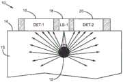
图1是根据实施例的用于监测植入传感器或植入物12的光学探测装置10的示意性侧视图。植入物12被嵌入到哺乳动物身体的组织15(在各种实施例中该组织15可以是一块附着至或者不附着至身体其余部分的组织)内。植入物12可以被嵌入到皮肤14的表面下。植入物12可以被嵌入和/或置于皮下组织内(例如,皮肤14表面下1到4mm的范围内)。植入物12能够响应于激励波长范围内的激励光发射至少一个处于发射波长范围内的分析物相关光信号。例如,所述分析物可以是葡萄糖或者组织15内的其他分析物。适当的光信号包括但不限于发光、生物发光、磷光、自发发光以及漫反射信号。在一些实施例中,植入物12包括一种或多种发光染料(例如,荧光染料),其光发射强度根据个体体内(例如,组织15内)的目标分析物的量或存在而变化。1 is a schematic side view of an
光源18被布置为从皮肤14的表面通过组织15向植入物12发射处于激励波长范围内的激励光。适当的光源包括但不限于激光器、半导体激光器、发光二极管(LED)和有机LED。探测器16、20被与光源18一起布置,以探测组织发射的处于发射波长范围内的光。适当的探测器包括但不限于光电二极管、互补金属氧化物半导体(CMOS)探测器或电荷耦合器件(CCD)探测器。尽管示出了多个探测器,但是可以采用单个和/或通用探测器。The
探测器16、20可以被过滤(例如,采用分色滤光器或其他适当滤光器),以测量所发射的处于所述波长范围内的光信号。例如,对葡萄糖浓度敏感的适当发光染料是响应于处于大约600到650nm(吸收峰647nm)的范围内的激励光(吸收)并处于大约670到750nm的发射波长范围(具有大约680nm的发射峰)内的Alexa

在一些实施例中,植入物12还能够响应于第二激励波长范围内的激励光发射至少一个处于第二发射波长范围内的分析物无关光信号。例如,植入物12可以含有分析物无关发光染料,该分析物无关发光染料作用在于控制指示器染料的非分析物物理或化学作用(例如,光致漂白或pH)。可以采用多个染料。所述分析物无关光信号不受存在于组织15内的分析物的调制,其提供用于归一化、偏移校正或内部校准的数据。所述分析物独立信号可以补偿化学、生理(例如,氧气、pH、氧化还原条件)或光学(例如,水、光吸收/散射混合、血红蛋白)的非分析物作用。或者,可以通过植入物12内的稳定参考染料提供分析物无关信号。适当的稳定参考材料包括但不限于镧化物掺杂晶体、镧化物掺杂纳米颗粒、量子点、螯合镧化物染料以及金属(例如,金或银)纳米颗粒。稳定的参考染料可以为其他信号提供基准信号(例如,以确定光致漂白)。In some embodiments, the
在装置10的操作中,激活光源18,从而从皮肤14的表面通过组织15向植入物12发射处于激励波长范围内的激励光。植入物中的染料吸收一些激励光,并发射取决于葡萄糖或其他分析物特性的荧光。植入物12可以朝所有方向发射光,所述光受到组织15的散射。植入物12发射的一些光通过组织15投射,并被探测器16、20的至少其中之一探测到。其能够提供原始分析物相关光信号。在采用参考光信号进行归一化的实施例中,对光源18(或者第二光源)进行激励,从而从皮肤14的表面向植入物12发射第二激励光。探测器16、20的至少其中之一响应于第二激励光测量组织15发射的通过皮肤14的表面的第二光信号。In operation of the
可以采用第二光信号对用于散射由植入物12发射的光的所述原始分析物相关光信号进行归一化。可以根据测得的光信号计算至少一个校正信号值。在一个范例中,可以通过植入物12发出的分析物无关光信号使来自植入物的原始分析物相关信号归一化。在执行分析物相关信号和/或分析物无关信号的光学读取之前,可以实施暗读取,以考虑背景或环境光,可以采用这一读数进一步校正所述信号,例如,通过减去背景。The raw analyte-related optical signal used to scatter the light emitted by the
在一些实施例中,可以由分析物相关信号和/或包括一个或多个参考信号的多个光信号的比值确定分析物值(例如,葡萄糖浓度)。在一个范例中,通过来自葡萄糖不敏感荧光基团(例如,Alexa


可以采用(例如)查找表格或校准曲线基于所述光信号确定分析物值。可以通过软件(在处理器上运行)和/或硬件实施对于分析物值的确定。例如,光学装置10可以包括微处理器。在一些实施例中,微处理器被编程为将测得的光信号值存储到存储器内并且/或者计算归一化的信号值和分析物浓度。或者,可以在单独的处理器或者与光学装置10通信的外部计算机内执行这些功能。所述外部处理器或计算机可以接收表示测得光信号的数据并计算校正信号值和分析物浓度。或者,可以提供多个处理器,例如,在所述光学装置内提供一个或多个与所述一个或多个外部处理器或计算机(无线或有线)通信的处理器。Analyte values can be determined based on the optical signals using, for example, a look-up table or calibration curve. The determination of the analyte value may be implemented by software (running on a processor) and/or hardware. For example, the
在一些利用两种植入物染料(例如,发光染料)的实施例中,有可能的是所述植入物染料可以共享或者重叠激励(吸收)或发射波长范围。在一个范例中,提供分析物相关发光信号的第一染料的发射波长范围共享用于提供分析物无关发光信号的第二染料的激励波长范围或与之重叠。在另一实施例中,所述第一染料和第二染料可以共享激励波长范围或者使所述激励波长范围重叠(从而可以采用公共光源),并发射处于不同发射波长范围内的光信号。在另一实施例中,所述第一染料和第二染料可以被处于不同激励波长范围内的光来激励,并发射处于相同或重叠发射波长范围内的光信号。In some embodiments utilizing two implant dyes (eg, luminescent dyes), it is possible that the implant dyes may share or overlap excitation (absorption) or emission wavelength ranges. In one example, the emission wavelength range of the first dye that provides the analyte-dependent luminescence signal shares or overlaps the excitation wavelength range of the second dye that provides the analyte-independent luminescence signal. In another embodiment, the first and second dyes may share or overlap excitation wavelength ranges (so that a common light source may be employed) and emit light signals in different emission wavelength ranges. In another embodiment, the first and second dyes may be excited by light in different excitation wavelength ranges and emit light signals in the same or overlapping emission wavelength ranges.
可以将植入物12嵌入到皮下组织内(例如,皮肤14表面下1到4mm的范围内)。在一些实施例中,注入12包括嵌有葡萄糖感测纳米球的水凝胶承架(hydrogel scaffold)。植入物12的设计可以采用可注射、可组织结合的血管化承架作为传感器。嵌入的纳米球发射响应于分析物(例如,填隙葡萄糖(interstitial glucose))的存在或浓度而改变强度和寿命的光。探测器16、20的每个与光源18之间的间隔距离决定用于探测来自植入物12的光信号的相应光路的深度。激光光源和探测带的组合为光通路。可以将光源18和探测器16、20布置为使得激励光的发射所通过的皮肤14的表面区域基本上位于探测光在从组织15向一个或多个探测器16、20传输时所通过的周围的皮肤14的表面区域之间。The
尽管图1仅示出了一个光源18和两个探测器16、20,但是在一些实施例中,光学装置10可以具有任何数量的光源以及任何数量的探测器。光学装置10可以具有处于多个光源和探测器之间的多个可能的间隔距离的组合。这样的多光源和/或多探测器实现可以允许提高光学装置10的灵活性。例如,由于植入物12的深度可以是因应用而异的,因而可以将具有多个光源和/或多个探测器的光学装置10用于多种应用。Although Figure 1 shows only one
可以将光学装置10配置为确保基本上只有波长处于激励波长范围内的光子才能抵达植入物12,并且只有波长处于发射波长范围内的光子才能抵达探测器16、20的至少其中之一。这样的布置能够使得从光源18抵达探测器16、20的可能导致测量误差的光子降至最低。The
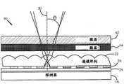
图2是根据实施例的用于监测植入物的光探测装置的示意性侧视图。透镜22的阵列与光圈24的阵列对准,以限制离轴光(off-axislight)向探测器16的传输。基于发射光相对于光圈的光轴30的入射角θ(文中又称为入射角),相对于探测器16对透镜阵列22和光圈阵列24定位,从而总体地限制从组织发射的向探测器16传播的光。光圈的光轴30可以基本上垂直于探测器16的表面。光圈阵列24的每个光圈可以基本上与透镜阵列22的透镜对准。也就是说,光圈的光轴30可以基本上与透镜的中心和/或轴同轴。例如,可以使光圈阵列24的基本上不透明的部分位于透镜边缘的下面。Figure 2 is a schematic side view of a light detection device for monitoring an implant, according to an embodiment. The array of
至少一层光控制膜26被与透镜阵列22和光圈阵列24布置到一起。光控制膜26可以基于发射光相对于膜26的入射角来限制从组织发射的光进入透镜阵列22和/或光圈阵列24。在一个范例中,光控制膜26是可在市场上从3MTM买到的VikutiTM光度微天窗私密膜,其能够阻挡穿过膜26的相对于垂直线具有大于期望的(例如,大于24度的)入射角的光。该私密膜包括微天窗组,其将避免大入射角的光抵达透镜阵列22。在其他实施例中,膜26包括按照类似于百叶窗的方式布置的交替的透明层和不透明层。以大于期望入射角的角度传播的光能够被吸收和/或反射。At least one layer of
设置至少一个滤光器(例如,分色滤光器或介质滤光器),从而将向探测器16传输的光限制为基本上处于期望发射波长范围以内的波长。由于光信号的探测是由相对于激励光具有低水平的返回信号主导的,因而滤光器28可以避免散射激励光蒙蔽探测器16。适当的滤光器包括带通、低通和高通滤光器,具体取决于应用所期望的发射波长范围。一些现代化滤光器由于改进了涂覆技术从而表现出了10-9的光剔除。此外,光学探测系统(例如,透镜阵列22、光圈阵列24等)的中间层可以包括抗反射涂层,以减少或者避免泄漏光通往探测器16。At least one filter (eg, a dichroic filter or a dielectric filter) is provided to limit the light transmitted to the
由于分色滤光器的基本特性的原因,保持高光剔除水平需要仔细的设计。分色滤光器的一个有损于光剔除的特性是随着入射角变化的“蓝移”,其中,分色滤光器的透射波长随着入射角而变化。对于植入物发射的探测光而言,在入射角和绝对光信号之间存在折衷。离开组织的光受到高度散射,并且在其到抵达皮肤表面时可以形成朗伯分布。发射光的收集效率与~NA2成比例,其中,NA=数值孔径=n sin θ,θ为入射角。为了提高收集效率,可以提高可容许的入射角θ,而又不使所述角度提高到允许激励光通过滤光器28的程度。Due to the fundamental nature of dichroic filters, maintaining the level of specular rejection requires careful design. One property of dichroic filters that detracts from light rejection is a "blue shift" with angle of incidence, where the transmitted wavelength of a dichroic filter changes with angle of incidence. For the probe light emitted by the implant, there is a trade-off between the angle of incidence and the absolute light signal. Light exiting tissue is highly scattered and can form a Lambertian distribution by the time it reaches the skin surface. The collection efficiency of the emitted light is proportional to ~NA2 , where NA = numerical aperture = n sin θ, and θ is the angle of incidence. To increase the collection efficiency, the allowable angle of incidence θ can be increased without increasing the angle to the extent that the excitation light is allowed to pass through the
透镜阵列22和光圈阵列24控制传播至探测器16的光的入射角θ。透镜阵列22和光圈阵列24将光限制为低于θ的入射角,在一些实施例中,将入射角选择为+/-20度。可以通过改变光圈的尺寸以及透镜阵列22内的微透镜的焦距而控制入射角θ。光圈越小,入射角θ越小。焦距越长,入射角θ越小。尽管未示出,但是可以采用间隔体来保持光圈阵列24的表面和透镜阵列22之间的间隔。The
图3是具有多个光圈25的光圈阵列24的平面图。在一些实施例中,通过对硅探测器,例如,图2所示的探测器16的表面上构图金属掩膜而构造光圈阵列24。可以将透镜阵列22制作为蚀刻璃或模制塑料。在一些实施例中,透镜阵列22是可从JENOPTIK OpticalSystems购买到的常规微透镜阵列。FIG. 3 is a plan view of an
图4是根据实施例的光学探测装置的示意性平面图。将图4的光学探测装置配置为贴片32。将至少一个光源(图4未示出)和探测器38布置到光读取器内,从而将贴片32配置为置于皮肤上。将光源布置为通过贴片32内的中央通孔34发射激励光,单个通用探测器38基本上围绕中央通孔34。在其他实施例中,可以采用多个探测器代替单个探测器38,例如,所述多个探测器基本上环绕中央通孔34,以探测处于多个发射波长范围内的光。在一些实施例中,所述光学探测装置包括至少一个处于中央通孔34内的光导部件36。所述光导部件36,例如,波导或光纤被布置为将激励光引导至皮肤。在一些实施例中,多个光源(图4中出于清晰起见未示出)被布置为通过中央通孔34(例如,利用一个或多个波导或光纤)发射处于多个不同激励波长范围内的激励光。4 is a schematic plan view of an optical detection device according to an embodiment. The optical detection device of FIG. 4 is configured as
作为一个可能的例子,一个或多个光源可以被布置为通过具有圆形截面的中央通孔34向皮肤发射激励光,从而通过皮肤的具有大约1mm的直径以及大约0.8mm2的对应激励表面积的基本上为圆形的表面区域发射激励光。探测器38具有方形截面积,该探测器38被设置为探测从皮肤的基本为方形的表面区域发射的光,其中,所述区域是探测光向探测器38传播时所经过的区域。所述探测表面区域基本上是具有10mm的边长的方形,因而总探测表面积为(10mm×10mm)-1mm2=99mm2。因此,在本范例中,探测表面积与激励表面积之比大于120:1。As a possible example, one or more light sources may be arranged to emit excitation light towards the skin through a central through-
图5是贴片32的示意性分解图。贴片32包括多个层。贴片32的尺寸可以是(例如)大约16mm的直径和大约1.6mm的厚度T。在一些实施例中,层可以包括具有大约200um的厚度的塑料盖40、具有大约100um的厚度的光控制膜26、具有大约200um的厚度的滤光器28、具有大约100um的厚度的透镜阵列22以及在具有大约200um的厚度的硅探测器层48上图案化的光圈阵列24。所述层还可以包括具有大约400um的厚度的印刷电路板(PCB)50、具有大约300um的厚度的电池52以及具有大约200um的厚度的外壳54。PCB 50可以包括一个或多个光源。PCB 50还可以包括处理电子装置和/或微处理器,其与探测器层48内的一个或多个探测器通信以接收表示处于发射波长范围内的探测光的数据,并且被编程为依据所述数据确定至少一个分析物值。可以贯穿层的堆叠形成中央通孔34(例如,在组装过程中蚀穿或者钻透所述堆叠)。FIG. 5 is a schematic exploded view of
图6是根据实施例的示出探测光学装置60的布置的用于监测植入物的光学探测装置的示意性侧视图。在该实施例中,由植入物和组织发射的处于发射波长范围内的光通过至少两层光控制膜62、64透射。所述的两层光控制膜62、64可以基于发射光相对于膜62、64的入射角来限制从组织发射的光进入透镜阵列22和/或光圈阵列。在一个范例中,光控制膜62包括具有与百叶窗类似的布置的交替透明层和不透明层。吸收以大于期望入射角的角度传播的光。光控制膜64可以包括可在市场上从3MTM买到的VikutiTM光度微型天窗私密膜,其阻挡具有相对于贯穿膜64的垂直线的大于期望入射角(例如,大于24度的)的光。Figure 6 is a schematic side view of an optical detection device for monitoring implants showing the arrangement of
在一些实施例中,光控制膜62和/或64可以基于入射角和方位角的组合来限制从组织发射的光进入透镜阵列22和/或光圈阵列24。例如,在光控制膜62和/或64包括多个微天窗的实施例中,光控制膜62和/或64可以在阻挡具有基本上垂直于微天窗的方位角的高入射角光方面是有效的,但是在阻挡具有基本上平行于微天窗的方位角的高入射角光方面相对无效。在一些这样的实施例中,两层光控制膜62、64可以是交叉排线的(crosshatched),或者可以以其他方式设置使得天窗与其他光控制元件不平行,由此使得光控制膜62、64合在一起对阻挡具有不同方位角的高入射角光有效。In some embodiments,
在一些实施例中,膜62、64可以基本上彼此相同,或者包括不同类型的私密膜。此外,可以将滤光器28(例如,分色滤光器或介质滤光器)置于光圈阵列24和探测器16之间,从而将向探测器16透射的发射光局限至基本上处于发射波长范围内的波长。图6的实施例的操作可以与前面描述的图1-2的实施例的操作类似。In some embodiments, the
图7是用于监测植入物的光探测装置的示意性侧视图。透镜122的阵列被与光圈24的阵列对准,以限制向探测器16透射的离轴光。相对于探测器16对透镜阵列122和光圈阵列24定位,从而根据发射光相对于光圈的光轴30的入射角θ限制从组织发射的向探测器16传播的光。光圈的光轴30可以基本上垂直于探测器16的表面。Figure 7 is a schematic side view of a light detection device for monitoring implants. The array of
透镜阵列122包括光阻挡元件72。可以将光阻挡元件72设置到光圈25之间以阻挡离轴光线74、76通过光圈25的传播。光阻挡元件72可以包括淀积在所设置的透镜阵列122的基板123的穴内的树脂、金属和/或金属膜。设置至少一个滤光器28,从而将向探测器16透射的发射光限制为基本上处于发射波长范围以内的波长。任选地,在这一实施例中可以包含一层或多层光控制膜。图7的实施例的操作可以与前面描述的图1-2的实施例的操作类似。
图8A-8D示出了根据实施例的处于各制造阶段内的具有光阻挡元件的透镜阵列122。图8A示出了可以制作为蚀刻玻璃或模制塑料的透镜阵列122的侧视图。在一些实施例中,透镜阵列122是可从JENOPTIK Optical Systems购买到的微透镜阵列。图8B示出了可以(例如)蚀刻或者整体模制到透镜阵列122的基板部分123内的穴78。如图8C所示,可以采用基本上不透明的材料填充穴78,以形成光阻挡元件72。所述光阻挡元件72可以由(例如)黑色树脂、金属和/或金属膜构成。如图8D所示,可以将光圈阵列24置于与透镜阵列122相邻的位置(在一些实施例中具有间隔体),从而将光阻挡元件72置于光圈25之间。在一些实施例中,通过在硅探测器的表面上构图金属掩膜而构造出光圈阵列24,并将具有光圈阵列24的探测器设置为与具有光阻挡元件72的透镜阵列122相邻,从而使得光阻挡元件72位于光圈25之间。8A-8D illustrate a
图9是根据实施例的光学探测装置210的示意性平面图。光学探测装置210包括四个探测器216、220、222、224以及光源218。光学探测装置210具有相对较大的探测器表面积与光源表面积的比值(文中又称为“表面积比”)。在植入物被嵌入到皮下组织内(例如,皮肤表面下1-4mm的范围内)时,所述大表面积比可以改善植入物信号的探测。具体而言,将光源218和四个探测器216、220、222、224布置为使得探测光在向探测器216、220、222、224传播时所通过的皮肤表面积与激励光的传输所通过的皮肤表面积之比至少为4:1。例如,在一个实施例中,光源218具有圆形截面,并且被设置为通过皮肤的基本为圆形的表面区域发射光,所述表面区域具有大约3mm的直径,大约1.5mm的半径以及大约7mm2的激励表面积。四个探测器216、220、222、224具有方形截面,并且被设置为探测从皮肤的四个基本上为方形的表面区域发射的光,所述四个基本上为方形的表面区域是探测光在向探测器传播时所通过的区域。所述四个探测表面区域的每个基本上是具有3mm的边长的方形,因而总的探测表面积为4×9mm2=36mm2。因此,在本范例中,探测表面积与激励表面积之比略大于5:1。FIG. 9 is a schematic plan view of an
在一些实施例中,可以将光学探测装置210配置为在至少两倍于植入物的深度的横向距离上探测植入物信号。例如,探测器216、220、222、224的至少其中之一的至少一部分沿横向与植入物的距离可以至少是该部分从远端地与植入物距离的两倍。例如,在嵌入到组织内4mm深的植入物的上方居中设置光源218的情况下,探测器216、220、222、224的至少其中之一的至少一部分可以距光源218的中心8mm。也就是说,探测器216、220、222、224的至少其中之一的最外边或拐角与光源218的中心的距离可以至少是植入物深度的两倍。在备选实施例中,例如,在具有单个或通用探测器的实施例中,探测器可以具有至少是植入物深度的两倍的半径。在其他实施例中,可以将光学探测装置210配置为在植入物深度的至少三倍、至少五倍或者任何其他适当倍数的横向距离上探测植入物信号。可操作以在距植入物相对较大的横向距离上探测植入物信号的光探测器装置210可以能够探测到发射信号的更大部分,尤其是在高散射环境内。俘获发射信号的更大部分能够改善探测准确度。In some embodiments, the
图10是根据实施例的光学探测装置310的示意性平面图。与光学探测装置210相比,在这一实施例中,四个探测器316、320、322、324被置于更加接近光源318的位置,从而使其包围或围绕光源318,并且探测表面积与激励表面积之比更大。例如,光源318可以具有圆形截面,并且被设置为通过皮肤的基本为圆形的表面区域发射光,所述表面区域具有大约2mm的直径,大约1mm的半径以及大约3.14mm2的激励表面积。四个探测器316、320、322、324具有方形截面,并且被设置为探测从皮肤的四个基本上为方形的表面区域发射的光,所述四个基本上为方形的表面区域是探测光在向探测器传播时所通过的区域。所述四个探测表面区域的每个基本上是具有6mm的边长的方形,因而总的探测表面积为4×36mm2=144mm2。因此,在本范例中,探测表面积与激励表面积之比略大于45:1。FIG. 10 is a schematic plan view of an
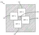
图11是根据另一实施例的光学探测装置410的方面的示意性平面图。在这一实施例中,五个圆形探测器428A、428B、428C、428D、428E围绕或者环绕中央通孔434。中央通孔434可以是装置410内的孔。将多个光源426布置为通过中央通孔434发射处于多个不同波长范围内的激励光。作为一个可能的例子,可以将光源426布置为通过具有圆形截面的中央通孔434向皮肤发射激励光,从而通过皮肤的具有大约3mm的直径以及大约7mm2的对应激励表面积的基本上为圆形的表面区域发射激励光。五个探测器428A、428B、428C、428D、428E具有圆形截面,并且被设置为探测从皮肤的五个基本上为圆形的表面区域发射的光,五个基本上为圆形的表面区域是探测光向探测器传播时所通过的区域。五个探测表面区域的每个基本上是具有5mm的直径的圆形,因为总的探测表面积为5×19.6mm=98mm2。因此,在本范例中,探测表面积与激励表面积之比略大于13:1。11 is a schematic plan view of aspects of an
本领域技术人员将清楚,在不背离本发明的范围的情况下可以通过很多种方式改变上面的实施例。例如,可以采用一个或多个光源、一个或多个探测器、滤光器和/或连接光学部件的光导元件的很多种不同的排列或布置实现本发明的装置和方法。例如,备选实施例可以具有不同尺寸和/或波长。实施例可以包括有线或无线手提读取器、无线皮肤贴片读取器、台式仪器、成像系统、智能电话附件和应用或者任何其他利用所公开的光学装置和算法的配置。It will be apparent to those skilled in the art that the above embodiments may be varied in many ways without departing from the scope of the present invention. For example, the apparatus and methods of the present invention may be implemented using many different arrangements or arrangements of one or more light sources, one or more detectors, filters, and/or light guide elements that connect optical components. For example, alternative embodiments may have different sizes and/or wavelengths. Embodiments may include wired or wireless handheld readers, wireless skin patch readers, benchtop instruments, imaging systems, smartphone accessories and applications, or any other configuration utilizing the disclosed optical devices and algorithms.
在文中描述的一些实施例中,监测装置可操作地同时发射激励光信号和探测发射信号。例如,可以采用光圈、光阻挡元件、滤光器、光控制膜等为这样的监测装置的探测器遮挡反射或者后向散射激励光。在其他实施例中,监测装置可操作地在一个时间周期内发射激励光信号,在另一停用激励光信号的时间周期内探测发射信号。In some embodiments described herein, the monitoring device is operable to simultaneously emit the excitation light signal and the detection emission signal. For example, apertures, light blocking elements, filters, light control films, etc. may be employed to shield the detectors of such monitoring devices from reflected or backscattered excitation light. In other embodiments, the monitoring device is operable to emit the excitation light signal during one time period and detect the emission signal during another time period when the excitation light signal is deactivated.
在一些情况下,组织的光学不均匀性可能很显著。因而,可以有利地利用单个光源和单个探测器确保每个颜色穿过相同的光路来通过组织。在一个实施例中,可以将光源设置为在光源和皮肤表面之间具有可移动滤光器组。类似地,可以利用单个光探测器代替单独的分立探测器元件。可以通过利用可移动或可更换滤光器,来使用所述探测器探测不同波长范围,从而实现多波长测量。可以通过控制转盘的机械致动器、滤光器条带或其他装置来实现滤光器的更换或移动。或者,可以用材料来涂覆光学滤光器,使得当其经受电流、电势、温度或者其他可控影响时,改变滤光特性,从而使单个光探测器能够起到探测多个波长范围的作用。In some cases, the optical inhomogeneity of the tissue may be significant. Thus, a single light source and a single detector can advantageously be utilized to ensure that each color travels through the tissue through the same optical path. In one embodiment, the light source may be arranged with a movable filter set between the light source and the skin surface. Similarly, a single photodetector can be used in place of separate discrete detector elements. Multi-wavelength measurements can be achieved by using the detector to detect different wavelength ranges using removable or replaceable filters. Filter replacement or movement can be accomplished by controlling a mechanical actuator of a turntable, filter strips, or other means. Alternatively, the optical filter can be coated with a material that, when subjected to current, electrical potential, temperature, or other controllable influence, changes the filtering properties, thereby enabling a single photodetector to function as detection of multiple wavelength ranges .
在一些实施例中,本发明的装置和方法利用率基于晶片的微光学装置。这些系统是通过平版印刷建立的,因而能够以低成本复制。所述技术允许对光学装置和探测器的层进行晶片级接合,之后将其划片成单个探测器系统。适当的部件包括蚀刻折射透镜,聚合物复制折射透镜、蚀刻二元(etched binary)透镜、复制二元透镜、复制全息图和复制体积全息图。In some embodiments, the devices and methods of the present invention utilize wafer-based micro-optic devices. These systems are built by lithography and thus can be reproduced at low cost. The techniques allow for wafer-level bonding of layers of optics and detectors, which are then diced into individual detector systems. Suitable components include etched refractive lenses, polymer replicated refractive lenses, etched binary lenses, replicated binary lenses, replicated holograms, and replicated volume holograms.
在一些实施例中,可以采用互补金属氧化物半导体(CMOS)探测器作为光学系统的集成部分。CMOS传感器的优点是将探测、激励和数字滤波电路集成到单片硅内的能力。最近宣布了一项新的技术sCMOS,研究人员通过这种技术能够将CMOS探测器当中的噪声极大地降至与电荷耦合器件(CCD)探测器相当的程度。CMOS集成解决方案的另一优点在于能够对信号执行锁定探测和数字滤波,以减少或消除环境光的影响。In some embodiments, complementary metal oxide semiconductor (CMOS) detectors may be employed as an integrated part of the optical system. The advantage of CMOS sensors is the ability to integrate detection, excitation, and digital filtering circuits into a single piece of silicon. Recently announced a new technology, sCMOS, by which researchers can greatly reduce the noise in CMOS detectors to a level comparable to that of charge-coupled device (CCD) detectors. Another advantage of a CMOS integrated solution is the ability to perform lock-in detection and digital filtering of the signal to reduce or eliminate the effects of ambient light.
尽管上文已经描述了各种实施例,但是应当理解,这些实施例只是以举例方式给出的,而非构成限制,可以做出各种形式和细节的变化。除了互斥的组合之外可以按照任何组合方式对文中描述的设备和/或方法的任何部分进行组合。文中描述的实施例可以包括所描述的不同实施例的功能、部件和/或特征的各种组合和/或亚组合。Although various embodiments have been described above, it should be understood that these embodiments have been presented by way of example and not limitation, and various changes in form and detail may be made. Any portion of the apparatus and/or methods described herein may be combined in any combination except in mutually exclusive combinations. The embodiments described herein may include various combinations and/or sub-combinations of the functions, components and/or features of the different embodiments described.
Claims (13)
Priority Applications (1)
| Application Number | Priority Date | Filing Date | Title |
|---|---|---|---|
| CN202010410590.0ACN111544011B (en) | 2013-06-06 | 2014-06-06 | Apparatus and methods for detecting optical signals from implanted sensors |
Applications Claiming Priority (5)
| Application Number | Priority Date | Filing Date | Title |
|---|---|---|---|
| US201361832065P | 2013-06-06 | 2013-06-06 | |
| US201361832078P | 2013-06-06 | 2013-06-06 | |
| US61/832,078 | 2013-06-06 | ||
| US61/832,065 | 2013-06-06 | ||
| PCT/US2014/041284WO2014197786A2 (en) | 2013-06-06 | 2014-06-06 | Apparatus and methods for detecting optical signals from implanted sensors |
Related Child Applications (1)
| Application Number | Title | Priority Date | Filing Date |
|---|---|---|---|
| CN202010410590.0ADivisionCN111544011B (en) | 2013-06-06 | 2014-06-06 | Apparatus and methods for detecting optical signals from implanted sensors |
Publications (2)
| Publication Number | Publication Date |
|---|---|
| CN105307559A CN105307559A (en) | 2016-02-03 |
| CN105307559Btrue CN105307559B (en) | 2020-06-05 |
Family
ID=52006018
Family Applications (2)
| Application Number | Title | Priority Date | Filing Date |
|---|---|---|---|
| CN201480031998.XAExpired - Fee RelatedCN105307559B (en) | 2013-06-06 | 2014-06-06 | Apparatus and method for detecting optical signals from implanted sensors |
| CN202010410590.0AExpired - Fee RelatedCN111544011B (en) | 2013-06-06 | 2014-06-06 | Apparatus and methods for detecting optical signals from implanted sensors |
Family Applications After (1)
| Application Number | Title | Priority Date | Filing Date |
|---|---|---|---|
| CN202010410590.0AExpired - Fee RelatedCN111544011B (en) | 2013-06-06 | 2014-06-06 | Apparatus and methods for detecting optical signals from implanted sensors |
Country Status (8)
| Country | Link |
|---|---|
| US (3) | US10219729B2 (en) |
| EP (2) | EP3003131B1 (en) |
| JP (3) | JP2016523608A (en) |
| CN (2) | CN105307559B (en) |
| AU (1) | AU2014274784B2 (en) |
| BR (1) | BR112015029988A2 (en) |
| CA (1) | CA2913474C (en) |
| WO (1) | WO2014197786A2 (en) |
Cited By (1)
| Publication number | Priority date | Publication date | Assignee | Title |
|---|---|---|---|---|
| US11864906B2 (en) | 2019-06-20 | 2024-01-09 | International Business Machines Corporation | LIDAR implantable biosensor for imaging biological tissue |
Families Citing this family (50)
| Publication number | Priority date | Publication date | Assignee | Title |
|---|---|---|---|---|
| EP3175780A1 (en) | 2003-12-18 | 2017-06-07 | Metronom Health, Inc. | Implantable biosensor and methods of use thereof |
| US9517023B2 (en) | 2009-06-01 | 2016-12-13 | Profusa, Inc. | Method and system for directing a localized biological response to an implant |
| US10010272B2 (en) | 2010-05-27 | 2018-07-03 | Profusa, Inc. | Tissue-integrating electronic apparatus |
| CA3012355C (en) | 2010-10-06 | 2023-05-16 | Profusa, Inc. | Tissue-integrating sensors |
| US10292784B2 (en)* | 2010-12-10 | 2019-05-21 | Illumix Surgical Canada Inc. | Illuminating surgical device |
| US8945209B2 (en) | 2011-05-20 | 2015-02-03 | Edwards Lifesciences Corporation | Encapsulated heart valve |
| US9693862B2 (en) | 2012-07-31 | 2017-07-04 | Edwards Lifesciences Corporation | Holders for prosthetic heart valves |
| EP2970318B1 (en) | 2013-03-14 | 2018-11-21 | Profusa, Inc. | Oxygen sensors comprising a polymer and a luminescent dye |
| CN113274007B (en) | 2013-03-14 | 2024-10-18 | 普罗菲尤萨股份有限公司 | Method and device for correcting an optical signal |
| EP3003131B1 (en) | 2013-06-06 | 2020-05-27 | Profusa, Inc. | Apparatus for detecting optical signals from implanted sensors |
| JP6539876B2 (en) | 2014-03-31 | 2019-07-10 | ソニー株式会社 | Measuring device, measuring method, program and recording medium |
| US10542920B2 (en)* | 2014-03-31 | 2020-01-28 | Sony Corporation | Measurement device, measurement method, program, and recording medium |
| US10092197B2 (en) | 2014-08-27 | 2018-10-09 | Apple Inc. | Reflective surfaces for PPG signal detection |
| US10215698B2 (en) | 2014-09-02 | 2019-02-26 | Apple Inc. | Multiple light paths architecture and obscuration methods for signal and perfusion index optimization |
| JP2016205954A (en)* | 2015-04-21 | 2016-12-08 | ルネサスエレクトロニクス株式会社 | Magnetic measuring device |
| WO2016210415A1 (en)* | 2015-06-25 | 2016-12-29 | Colvin Arthur E Jr | Transcutaneous reader for use with implantable analyte sensors |
| AU2016315838B2 (en) | 2015-09-02 | 2022-07-28 | Metronom Health, Inc. | Systems and methods for continuous health monitoring using an opto-enzymatic analyte sensor |
| US10080653B2 (en) | 2015-09-10 | 2018-09-25 | Edwards Lifesciences Corporation | Limited expansion heart valve |
| US10687717B1 (en)* | 2015-09-30 | 2020-06-23 | Apple Inc. | PPG sensor having light arrival angle control at detector |
| US10667904B2 (en) | 2016-03-08 | 2020-06-02 | Edwards Lifesciences Corporation | Valve implant with integrated sensor and transmitter |
| US10082387B2 (en)* | 2016-03-09 | 2018-09-25 | UbiQD, Inc. | Fluorescent liquid penetrants and methods of nondestructive testing |
| JP2017213040A (en)* | 2016-05-30 | 2017-12-07 | セイコーエプソン株式会社 | Biological information acquisition apparatus and biological information acquisition method |
| EP3558118A4 (en) | 2016-12-21 | 2021-02-24 | Profusa, Inc. | Polymerizable near-ir dyes |
| WO2018119400A1 (en) | 2016-12-22 | 2018-06-28 | Profusa, Inc. | System and single-channel luminescent sensor for and method of determining analyte value |
| US10918322B2 (en) | 2017-02-13 | 2021-02-16 | Apple Inc. | Light restriction designs in optical sensing applications having shared windows |
| US10463485B2 (en) | 2017-04-06 | 2019-11-05 | Edwards Lifesciences Corporation | Prosthetic valve holders with automatic deploying mechanisms |
| US10792378B2 (en) | 2017-04-28 | 2020-10-06 | Medtronics Minimed, Inc. | Using a blue-shifted reference dye in an optical glucose assay |
| EP3614969B1 (en) | 2017-04-28 | 2023-05-03 | Edwards Lifesciences Corporation | Prosthetic heart valve with collapsible holder |
| DE102017110216B4 (en)* | 2017-05-11 | 2023-03-09 | OSRAM Opto Semiconductors Gesellschaft mit beschränkter Haftung | Optoelectronic sensor module and method for producing an optoelectronic sensor module |
| WO2018237020A1 (en) | 2017-06-21 | 2018-12-27 | Edwards Lifesciences Corporation | CARDIAC EXPANDED CARDIAC VALVES IN THE FORM OF DOUBLE THREAD |
| BR112019027709A2 (en) | 2017-06-29 | 2020-08-11 | Profusa, Inc. | integration sensors in multi-analyte detection fabrics |
| CN114947741B (en) | 2017-09-26 | 2025-08-08 | 苹果公司 | Concentric structures for optical sensing |
| EP3694562A2 (en) | 2017-10-13 | 2020-08-19 | Edwards Lifesciences Corporation | Method for sterilizing heart valves |
| EP3473172A1 (en)* | 2017-10-20 | 2019-04-24 | Universität Zürich | Apparatus for measuring optical parameters in scattering media |
| CN107677604A (en)* | 2017-10-31 | 2018-02-09 | 广东省测试分析研究所(中国广州分析测试中心) | A kind of miniaturization detection means of Visual retrieval card |
| CN109717876B (en)* | 2017-10-31 | 2023-12-26 | 心脏起搏器股份公司 | Structural diffusion membrane for chemical sensors |
| EP3729059B1 (en)* | 2017-12-19 | 2023-05-03 | The Research Foundation for the State University of New York | System for detecting biomarkers comprising an implantable spr sensor |
| JP2021508548A (en)* | 2017-12-28 | 2021-03-11 | プロフサ,インコーポレイテッド | Systems and methods for analyzing biochemical sensor data |
| KR102620446B1 (en)* | 2018-06-22 | 2024-01-03 | 삼성전자주식회사 | Sensor including first optical member having reflection characteristics and second optical member having absorption characteristics absorbable reflected light by first optical member and electronic device with the same |
| CA3104346A1 (en) | 2018-06-27 | 2020-01-02 | Profusa, Inc. | Near-ir glucose sensors |
| WO2020163145A1 (en) | 2019-02-05 | 2020-08-13 | Edwards Lifesciences Corporation | Prosthetic heart valve with suture loop preventing member |
| WO2021025979A1 (en) | 2019-08-02 | 2021-02-11 | Edwards Lifesciences Corporation | Rotary application of fibrous material to medical devices |
| WO2021035047A1 (en) | 2019-08-20 | 2021-02-25 | Profusa, Inc. | Optical filter device, system, and method for improved optical rejection of out-of-band wavelengths |
| KR20220106815A (en)* | 2019-12-06 | 2022-07-29 | 브로리스 센서 테크놀로지, 유에이비 | Systems and methods for measuring the concentration of an analyte |
| CR20210655A (en) | 2019-12-16 | 2022-06-02 | Edwards Lifesciences Corp | Valve holder assembly with suture looping protection |
| US11561345B2 (en)* | 2020-02-14 | 2023-01-24 | Google Llc | Apertures for reduced dynamic crosstalk and stray light control |
| US12204125B2 (en) | 2020-02-19 | 2025-01-21 | Profusa, Inc. | Optical filter device, system, and methods for improved optical rejection of high angle of incidence (AOI) light |
| US12317024B2 (en)* | 2021-01-14 | 2025-05-27 | Apple Inc. | Electronic devices with skin sensors |
| EP4288764B1 (en)* | 2021-02-03 | 2025-07-09 | Siemens Healthcare Diagnostics, Inc. | High-sensitivity chemiluminescence detection systems and methods |
| EP4575467A1 (en)* | 2023-12-22 | 2025-06-25 | F. Hoffmann-La Roche AG | Techniques for illumination and detection in analytical analyzers |
Citations (1)
| Publication number | Priority date | Publication date | Assignee | Title |
|---|---|---|---|---|
| US5962852A (en)* | 1996-01-26 | 1999-10-05 | Roche Diagnostics Gmbh | Process and device for determining an analyte contained in a scattering matrix |
Family Cites Families (227)
| Publication number | Priority date | Publication date | Assignee | Title |
|---|---|---|---|---|
| JPS59189828A (en) | 1983-04-08 | 1984-10-27 | 萩原 文二 | Subcateneous measuring sensor and apparatus of blood coloring matter |
| US4703756A (en) | 1986-05-06 | 1987-11-03 | The Regents Of The University Of California | Complete glucose monitoring system with an implantable, telemetered sensor module |
| US4975581A (en)* | 1989-06-21 | 1990-12-04 | University Of New Mexico | Method of and apparatus for determining the similarity of a biological analyte from a model constructed from known biological fluids |
| US6040194A (en) | 1989-12-14 | 2000-03-21 | Sensor Technologies, Inc. | Methods and device for detecting and quantifying substances in body fluids |
| US5342789A (en) | 1989-12-14 | 1994-08-30 | Sensor Technologies, Inc. | Method and device for detecting and quantifying glucose in body fluids |
| US5094958A (en) | 1990-08-30 | 1992-03-10 | Fiberchem Inc. | Method of self-compensating a fiber optic chemical sensor |
| US5284140A (en) | 1992-02-11 | 1994-02-08 | Eli Lilly And Company | Acrylic copolymer membranes for biosensors |
| IL107396A (en)* | 1992-11-09 | 1997-02-18 | Boehringer Mannheim Gmbh | Method and apparatus for analytical determination of glucose in a biological matrix |
| US5462880A (en) | 1993-09-13 | 1995-10-31 | Optical Sensors Incorporated | Ratiometric fluorescence method to measure oxygen |
| US5882494A (en) | 1995-03-27 | 1999-03-16 | Minimed, Inc. | Polyurethane/polyurea compositions containing silicone for biosensor membranes |
| JPH08304741A (en)* | 1995-05-09 | 1996-11-22 | Olympus Optical Co Ltd | Optical system including diffraction optical element |
| AU708051B2 (en) | 1995-06-09 | 1999-07-29 | Conmed Israel Ltd | Sensor, method and device for optical blood oximetry |
| US5657754A (en)* | 1995-07-10 | 1997-08-19 | Rosencwaig; Allan | Apparatus for non-invasive analyses of biological compounds |
| US6104945A (en)* | 1995-08-01 | 2000-08-15 | Medispectra, Inc. | Spectral volume microprobe arrays |
| JP3350918B2 (en) | 1996-03-26 | 2002-11-25 | 株式会社高岳製作所 | Two-dimensional array confocal optical device |
| US5711861A (en) | 1995-11-22 | 1998-01-27 | Ward; W. Kenneth | Device for monitoring changes in analyte concentration |
| EP0862648B1 (en) | 1995-11-22 | 2004-10-06 | Medtronic MiniMed, Inc. | Detection of biological molecules using chemical amplification and optical sensors |
| US6002954A (en) | 1995-11-22 | 1999-12-14 | The Regents Of The University Of California | Detection of biological molecules using boronate-based chemical amplification and optical sensors |
| US6766183B2 (en) | 1995-11-22 | 2004-07-20 | Medtronic Minimed, Inc. | Long wave fluorophore sensor compounds and other fluorescent sensor compounds in polymers |
| AUPN814496A0 (en) | 1996-02-19 | 1996-03-14 | Monash University | Dermal penetration enhancer |
| GB9616896D0 (en) | 1996-08-12 | 1996-09-25 | British Tech Group | Pharmaceutical compositions |
| US6544193B2 (en)* | 1996-09-04 | 2003-04-08 | Marcio Marc Abreu | Noninvasive measurement of chemical substances |
| WO1998022820A1 (en) | 1996-11-21 | 1998-05-28 | Lawrence Livermore National Laboratory | Detection of biological molecules using boronate-based chemical amplification and optical sensors |
| US6043437A (en) | 1996-12-20 | 2000-03-28 | Alfred E. Mann Foundation | Alumina insulation for coating implantable components and other microminiature devices |
| US8527026B2 (en) | 1997-03-04 | 2013-09-03 | Dexcom, Inc. | Device and method for determining analyte levels |
| US6741877B1 (en) | 1997-03-04 | 2004-05-25 | Dexcom, Inc. | Device and method for determining analyte levels |
| US6001067A (en) | 1997-03-04 | 1999-12-14 | Shults; Mark C. | Device and method for determining analyte levels |
| US7192450B2 (en) | 2003-05-21 | 2007-03-20 | Dexcom, Inc. | Porous membranes for use with implantable devices |
| WO1999006821A1 (en) | 1997-08-01 | 1999-02-11 | Presens Precision Sensing Gmbh | Method and device for referencing fluorescence intensity signals |
| US5895658A (en) | 1997-09-17 | 1999-04-20 | Fossel; Eric T. | Topical delivery of L-arginine to cause tissue warming |
| US8465425B2 (en) | 1998-04-30 | 2013-06-18 | Abbott Diabetes Care Inc. | Analyte monitoring device and methods of use |
| US6175752B1 (en) | 1998-04-30 | 2001-01-16 | Therasense, Inc. | Analyte monitoring device and methods of use |
| US8346337B2 (en) | 1998-04-30 | 2013-01-01 | Abbott Diabetes Care Inc. | Analyte monitoring device and methods of use |
| GB9814506D0 (en) | 1998-07-03 | 1998-09-02 | Stanley Christopher J | Optical sensor for insitu measurement of analytes |
| WO2000001294A1 (en) | 1998-07-04 | 2000-01-13 | Whitland Research Limited | Non-invasive measurement of blood analytes |
| US6013122A (en) | 1998-08-18 | 2000-01-11 | Option Technologies, Inc. | Tattoo inks |
| EP1105169A1 (en) | 1998-08-20 | 2001-06-13 | Cook Incorporated | Coated implantable medical device |
| KR100682488B1 (en)* | 1998-08-26 | 2007-02-15 | 센서즈 포 메드슨 앤드 사이언스 인코포레이티드 | Optical system |
| US6602678B2 (en) | 1998-09-04 | 2003-08-05 | Powderject Research Limited | Non- or minimally invasive monitoring methods |
| US20030099682A1 (en) | 1998-11-20 | 2003-05-29 | Francis Moussy | Apparatus and method for control of tissue/implant interactions |
| US6366794B1 (en) | 1998-11-20 | 2002-04-02 | The University Of Connecticut | Generic integrated implantable potentiostat telemetry unit for electrochemical sensors |
| US6352502B1 (en)* | 1998-12-03 | 2002-03-05 | Lightouch Medical, Inc. | Methods for obtaining enhanced spectroscopic information from living tissue, noninvasive assessment of skin condition and detection of skin abnormalities |
| US6783937B1 (en) | 1999-02-25 | 2004-08-31 | Pall Corporation | Negatively charged membrane |
| US8346363B2 (en) | 1999-03-05 | 2013-01-01 | Metacure Limited | Blood glucose level control |
| US6475750B1 (en) | 1999-05-11 | 2002-11-05 | M-Biotech, Inc. | Glucose biosensor |
| US6366793B1 (en) | 1999-09-10 | 2002-04-02 | Beckman Coulter, Inc. | Minimally invasive methods for measuring analtes in vivo |
| US20050119737A1 (en) | 2000-01-12 | 2005-06-02 | Bene Eric A. | Ocular implant and methods for making and using same |
| EP1255772A2 (en) | 2000-02-11 | 2002-11-13 | The Texas A & M University System | Biosensor compositions and methods of use |
| DE10011284B4 (en) | 2000-03-08 | 2007-06-28 | Disetronic Licensing Ag | Apparatus for in vivo measurement of the concentration of an ingredient of a body fluid |
| WO2001075450A2 (en) | 2000-04-04 | 2001-10-11 | The Regents Of The University Of California | Fluorescent lifetime assays for non-invasive quantification of analytes |
| JP2001320034A (en) | 2000-05-09 | 2001-11-16 | Sony Corp | Solid-state image sensing element and its manufacturing method |
| US6565960B2 (en) | 2000-06-01 | 2003-05-20 | Shriners Hospital Of Children | Polymer composite compositions |
| AU2001279127A1 (en) | 2000-08-01 | 2002-02-13 | University Of Washington | Methods and devices to modulate the wound response |
| BR0112871A (en) | 2000-08-04 | 2003-04-22 | Sensors For Med & Science Inc | Analyte detection for aqueous environments |
| GB0025147D0 (en) | 2000-10-13 | 2000-11-29 | Torsana Diabetes Diagnostics A | Optical sensor for in situ measurement of analytes |
| DE10054382A1 (en) | 2000-10-27 | 2002-05-08 | Attomol Gmbh Molekulare Diagno | Method and test kit for the detection of analytes in a sample |
| US6642015B2 (en) | 2000-12-29 | 2003-11-04 | Minimed Inc. | Hydrophilic polymeric material for coating biosensors |
| US8069254B2 (en) | 2001-02-28 | 2011-11-29 | Sharp Laboratories Of America, Inc. | Communication period management in a communication system |
| US6694158B2 (en) | 2001-04-11 | 2004-02-17 | Motorola, Inc. | System using a portable detection device for detection of an analyte through body tissue |
| US20040152963A1 (en) | 2001-04-27 | 2004-08-05 | March Wayne Front | Apparatus for measuring blood glucose concentrations |
| FI20010898A0 (en) | 2001-04-30 | 2001-04-30 | Ylae Herttuala Seppo | Extracellular superoxide dismutase (EC-SOD) gene therapy to prevent restenosis |
| EP1385570B1 (en) | 2001-04-30 | 2006-09-13 | Medtronic, Inc. | Implantable medical device and patch system |
| JP3806616B2 (en)* | 2001-06-04 | 2006-08-09 | 浜松ホトニクス株式会社 | Pinhole detector |
| US6844028B2 (en) | 2001-06-26 | 2005-01-18 | Accelr8 Technology Corporation | Functional surface coating |
| GB0116853D0 (en) | 2001-07-10 | 2001-09-05 | Torsana Diabetes Diagnostics A | Optical sensor containing particles for in SITU measurement of analytes |
| US6702857B2 (en) | 2001-07-27 | 2004-03-09 | Dexcom, Inc. | Membrane for use with implantable devices |
| AU2002337666A1 (en)* | 2001-08-03 | 2003-02-17 | Joseph A. Izatt | Aspects of basic oct engine technologies for high speed optical coherence tomography and light source and other improvements in oct |
| JP2003054025A (en) | 2001-08-09 | 2003-02-26 | Nippon Sheet Glass Co Ltd | Image transmitter |
| WO2003026503A1 (en) | 2001-09-25 | 2003-04-03 | Vital Medical Ltd. | Multiparametric apparatus for monitoring multiple tissue vitality parameters |
| EP1519678A2 (en) | 2001-10-02 | 2005-04-06 | Alfred E. Mann Institute for Biomedical Engineering at the University of Southern California | Internal biochemical sensing device |
| KR100903761B1 (en) | 2001-11-27 | 2009-06-19 | 타키론 가부시기가이샤 | Implant Materials and Manufacturing Method Thereof |
| US7202947B2 (en) | 2001-12-19 | 2007-04-10 | Wisconsin Alumni Research Foundation | Depth-resolved fluorescence instrument with angled excitation |
| JP4122787B2 (en) | 2002-01-30 | 2008-07-23 | 岩崎通信機株式会社 | Electronic image converter |
| US7613491B2 (en) | 2002-05-22 | 2009-11-03 | Dexcom, Inc. | Silicone based membranes for use in implantable glucose sensors |
| US8260393B2 (en) | 2003-07-25 | 2012-09-04 | Dexcom, Inc. | Systems and methods for replacing signal data artifacts in a glucose sensor data stream |
| GB0204640D0 (en) | 2002-02-27 | 2002-04-10 | Torsana Diabetes Diagnostics A | Injection apparatus |
| US7738945B2 (en)* | 2002-04-19 | 2010-06-15 | University Of Washington | Method and apparatus for pseudo-projection formation for optical tomography |
| US7153265B2 (en) | 2002-04-22 | 2006-12-26 | Medtronic Minimed, Inc. | Anti-inflammatory biosensor for reduced biofouling and enhanced sensor performance |
| US7813780B2 (en) | 2005-12-13 | 2010-10-12 | Medtronic Minimed, Inc. | Biosensors and methods for making and using them |
| US20030208166A1 (en) | 2002-05-06 | 2003-11-06 | Schwartz Anthony H. | Implantable device with free-flowing exit and uses thereof |
| WO2003099169A1 (en) | 2002-05-20 | 2003-12-04 | Orbus Medical Technologies Inc. | Drug eluting implantable medical device |
| US7226978B2 (en) | 2002-05-22 | 2007-06-05 | Dexcom, Inc. | Techniques to improve polyurethane membranes for implantable glucose sensors |
| US20050118726A1 (en) | 2002-08-26 | 2005-06-02 | Schultz Jerome S. | System and method for detecting bioanalytes and method for producing a bioanalyte sensor |
| US7162289B2 (en) | 2002-09-27 | 2007-01-09 | Medtronic Minimed, Inc. | Method and apparatus for enhancing the integrity of an implantable sensor device |
| US20040106951A1 (en) | 2002-11-22 | 2004-06-03 | Edman Carl Frederick | Use of electric fields to minimize rejection of implanted devices and materials |
| US20040143221A1 (en) | 2002-12-27 | 2004-07-22 | Shadduck John H. | Biomedical implant for sustained agent release |
| US7811231B2 (en) | 2002-12-31 | 2010-10-12 | Abbott Diabetes Care Inc. | Continuous glucose monitoring system and methods of use |
| US20040133079A1 (en) | 2003-01-02 | 2004-07-08 | Mazar Scott Thomas | System and method for predicting patient health within a patient management system |
| US7406345B2 (en) | 2003-02-14 | 2008-07-29 | Eyesense Ag | Apparatus for measuring an analyte concentration from an ocular fluid |
| US7772286B2 (en) | 2003-02-28 | 2010-08-10 | Eyesense Ag | Polyvinyl alcohol copolymers comprising biomolecules |
| JP2004267613A (en) | 2003-03-11 | 2004-09-30 | Olympus Corp | Glucose concentration measuring apparatus |
| US6965791B1 (en) | 2003-03-26 | 2005-11-15 | Sorenson Medical, Inc. | Implantable biosensor system, apparatus and method |
| US6828572B2 (en) | 2003-04-01 | 2004-12-07 | Axcelis Technologies, Inc. | Ion beam incident angle detector for ion implant systems |
| US7134999B2 (en) | 2003-04-04 | 2006-11-14 | Dexcom, Inc. | Optimized sensor geometry for an implantable glucose sensor |
| US20070010702A1 (en) | 2003-04-08 | 2007-01-11 | Xingwu Wang | Medical device with low magnetic susceptibility |
| US20040225222A1 (en)* | 2003-05-08 | 2004-11-11 | Haishan Zeng | Real-time contemporaneous multimodal imaging and spectroscopy uses thereof |
| US7186789B2 (en) | 2003-06-11 | 2007-03-06 | Advanced Cardiovascular Systems, Inc. | Bioabsorbable, biobeneficial polyester polymers for use in drug eluting stent coatings |
| US20040259270A1 (en) | 2003-06-19 | 2004-12-23 | Wolf David E. | System, device and method for exciting a sensor and detecting analyte |
| US7927519B2 (en) | 2003-07-30 | 2011-04-19 | Eyesense Ag | Reflection hologram sensor in contact lens |
| US20050027175A1 (en) | 2003-07-31 | 2005-02-03 | Zhongping Yang | Implantable biosensor |
| US7519408B2 (en) | 2003-11-19 | 2009-04-14 | Dexcom, Inc. | Integrated receiver for continuous analyte sensor |
| US7591801B2 (en) | 2004-02-26 | 2009-09-22 | Dexcom, Inc. | Integrated delivery device for continuous glucose sensor |
| DE602004028020D1 (en) | 2003-08-07 | 2010-08-19 | Eyesense Ag | OPHTHALMIC SENSOR |
| US9687368B2 (en) | 2003-08-13 | 2017-06-27 | Medtronic Vascular, Inc. | Biocompatible controlled release coatings for medical devices and related methods |
| WO2005032418A2 (en) | 2003-10-01 | 2005-04-14 | University Of Washington | Novel porous biomaterials |
| ATE482650T1 (en) | 2003-11-03 | 2010-10-15 | Microchips Inc | MEDICAL DEVICE FOR MEASURING GLUCOSE |
| AU2004293075A1 (en) | 2003-11-20 | 2005-06-09 | Angiotech International Ag | Soft tissue implants and anti-scarring agents |
| US7496392B2 (en) | 2003-11-26 | 2009-02-24 | Becton, Dickinson And Company | Fiber optic device for sensing analytes |
| US20050148003A1 (en) | 2003-11-26 | 2005-07-07 | Steven Keith | Methods of correcting a luminescence value, and methods of determining a corrected analyte concentration |
| US8423114B2 (en) | 2006-10-04 | 2013-04-16 | Dexcom, Inc. | Dual electrode system for a continuous analyte sensor |
| ATE480761T1 (en) | 2003-12-05 | 2010-09-15 | Dexcom Inc | CALIBRATION METHODS FOR A CONTINUOUSLY WORKING ANALYTICAL SENSOR |
| US7433042B1 (en) | 2003-12-05 | 2008-10-07 | Surface Optics Corporation | Spatially corrected full-cubed hyperspectral imager |
| EP3175780A1 (en) | 2003-12-18 | 2017-06-07 | Metronom Health, Inc. | Implantable biosensor and methods of use thereof |
| GB0329849D0 (en) | 2003-12-23 | 2004-01-28 | Precisense As | Fluorometers |
| US20060002969A1 (en) | 2004-01-27 | 2006-01-05 | University Of Washington | Methods for reducing the foreign body reaction |
| JP2005227238A (en)* | 2004-02-16 | 2005-08-25 | Hamamatsu Photonics Kk | Pinhole inspection device |
| US7450980B2 (en) | 2004-03-31 | 2008-11-11 | Terumo Kabushiki Kaisha | Intracorporeal substance measuring assembly |
| US20050245799A1 (en) | 2004-05-03 | 2005-11-03 | Dexcom, Inc. | Implantable analyte sensor |
| WO2005107863A2 (en) | 2004-05-04 | 2005-11-17 | University Of Rochester | Implantable bio-electro-physiologic interface matrix |
| GB0411162D0 (en) | 2004-05-19 | 2004-06-23 | Precisense As | Optical sensor for in vivo detection of analyte |
| US8690865B2 (en) | 2004-05-28 | 2014-04-08 | Georgia Tech Research Corporation | Methods and devices for thermal treatment |
| WO2005120631A1 (en) | 2004-06-02 | 2005-12-22 | Carl Frederick Edman | Use of electric fields to minimize rejection of implanted devices and materials |
| CN100496385C (en) | 2004-06-14 | 2009-06-10 | 视觉股份公司 | Combined apparatus for measuring the blood glucose level from an ocular fluid |
| US20070004046A1 (en) | 2005-07-01 | 2007-01-04 | Platypus Technologies, Llc | Detection of analytes |
| US7968085B2 (en) | 2004-07-05 | 2011-06-28 | Ascendis Pharma A/S | Hydrogel formulations |
| GB0416732D0 (en) | 2004-07-27 | 2004-09-01 | Precisense As | A method and apparatus for measuring the phase shift induced in a light signal by a sample |
| WO2006127023A2 (en) | 2004-08-24 | 2006-11-30 | University Of South Florida | Epoxy enhanced polymer membrane to increase durability of biosensors |
| US7257279B2 (en)* | 2004-09-20 | 2007-08-14 | 3M Innovative Properties Company | Systems and methods for biosensing and microresonator sensors for same |
| US20060241364A1 (en)* | 2004-10-01 | 2006-10-26 | Academisch Medisch Centrum Of The University Van Amsterdam | System and method for imaging the reflectance of a substrate |
| US7166680B2 (en) | 2004-10-06 | 2007-01-23 | Advanced Cardiovascular Systems, Inc. | Blends of poly(ester amide) polymers |
| US7248907B2 (en) | 2004-10-23 | 2007-07-24 | Hogan Josh N | Correlation of concurrent non-invasively acquired signals |
| GB0426822D0 (en) | 2004-12-07 | 2005-01-12 | Precisense As | Sensor for detection of glucose |
| GB0426993D0 (en)* | 2004-12-09 | 2005-01-12 | Council Cent Lab Res Councils | Apparatus for depth-selective raman spectroscopy |
| US7282694B2 (en)* | 2004-12-15 | 2007-10-16 | Avago Technologies Ecbu Ip (Singapore) Pte Ltd | Optical navigation system having a ring pixel array |
| US7280201B2 (en)* | 2004-12-17 | 2007-10-09 | Avago Technologies General Ip Pte Ltd | Sensor having integrated light detector and/or light source |
| JP2008535548A (en) | 2005-03-21 | 2008-09-04 | アボット ダイアビーティーズ ケア インコーポレイテッド | Method and system for providing an integrated pharmaceutical infusion / specimen monitoring system |
| CA2602259A1 (en) | 2005-03-29 | 2006-10-05 | Arkal Medical, Inc. | Devices, systems, methods and tools for continuous glucose monitoring |
| US20060229508A1 (en) | 2005-03-30 | 2006-10-12 | Kermani Mahyar Z | Adhesive fluorescence measurement patch |
| US20060270919A1 (en) | 2005-05-11 | 2006-11-30 | Mytek, Llc | Biomarkers sensing |
| JP2008541881A (en) | 2005-05-27 | 2008-11-27 | ジョンソン・アンド・ジョンソン・コンシューマー・カンパニーズ・インコーポレイテッド | Isolated patches for viral diseases |
| US20070038046A1 (en) | 2005-08-09 | 2007-02-15 | Hayter Paul G | Kinematic fluorescence measurement band |
| US7704704B2 (en) | 2005-09-28 | 2010-04-27 | The Texas A&M University System | Implantable system for glucose monitoring using fluorescence quenching |
| US20070098594A1 (en)* | 2005-11-03 | 2007-05-03 | Roche Molecular Systems, Inc. | Analytical multi-spectral optical detection system |
| US8515518B2 (en) | 2005-12-28 | 2013-08-20 | Abbott Diabetes Care Inc. | Analyte monitoring |
| US8114269B2 (en) | 2005-12-30 | 2012-02-14 | Medtronic Minimed, Inc. | System and method for determining the point of hydration and proper time to apply potential to a glucose sensor |
| US8135450B2 (en) | 2006-01-20 | 2012-03-13 | Esenaliev Rinat O | Noninvasive glucose sensing methods and systems |
| US7286232B2 (en) | 2006-02-15 | 2007-10-23 | Li-Cor, Inc. | Fluorescence filtering system and method for molecular imaging |
| US20070232873A1 (en) | 2006-03-16 | 2007-10-04 | The Board Of Regents Of The University Of Texas Syatem | Noninvasive, accurate glucose monitoring with oct by using tissue warming and temperature control |
| CN101351153A (en)* | 2006-03-22 | 2009-01-21 | 松下电器产业株式会社 | Biosensors and Component Concentration Measuring Devices |
| US20100202966A1 (en) | 2006-03-28 | 2010-08-12 | Yossi Gross | Implantable Sensor |
| US7809441B2 (en) | 2006-05-17 | 2010-10-05 | Cardiac Pacemakers, Inc. | Implantable medical device with chemical sensor and related methods |
| US20080020012A1 (en) | 2006-06-22 | 2008-01-24 | Ju Young M | Collagen scaffolds, medical implants with same and methods of use |
| JP2009544988A (en)* | 2006-07-20 | 2009-12-17 | コーニンクレッカ フィリップス エレクトロニクス エヌ ヴィ | Multicolor biosensor |
| ATE413836T1 (en) | 2006-07-24 | 2008-11-15 | Eyesense Ag | DEVICE FOR MEASURING AN ANALYTE IN AN EYE FLUID |
| EP2097508A4 (en) | 2006-12-07 | 2011-10-26 | Univ Ohio State Res Found | IN VIVO BIODETECTION SYSTEM BASED ON THE OPTICAL RESPONSE OF ELECTRONIC POLYMERS |
| US20080139903A1 (en) | 2006-12-08 | 2008-06-12 | Isense Corporation | Method and apparatus for insertion of a sensor using an introducer |
| EP2104954B1 (en) | 2007-01-17 | 2022-03-16 | The Board of Trustees of the University of Illinois | Optical systems fabricated by printing-based assembly |
| DE102007003341B4 (en) | 2007-01-17 | 2018-01-04 | Eyesense Ag | Eyepiece sensor and measuring system for detecting an analyte in an eye fluid |
| WO2008141241A1 (en) | 2007-05-10 | 2008-11-20 | Glumetrics, Inc. | Equilibrium non-consuming fluorescence sensor for real time intravascular glucose measurement |
| DE102007024642A1 (en) | 2007-05-24 | 2008-11-27 | Eyesense Ag | Hydrogel implant for sensor of metabolites on the eye |
| WO2008154312A1 (en) | 2007-06-08 | 2008-12-18 | Dexcom, Inc. | Integrated medicament delivery device for use with continuous analyte sensor |
| GB0717150D0 (en) | 2007-09-04 | 2007-10-17 | Univ Warwick | Apparatus and method |
| AU2008325237B2 (en)* | 2007-11-05 | 2014-05-01 | Biosensor, Inc. | Optical sensor for determining the concentration of an analyte |
| JP5631215B2 (en) | 2007-11-21 | 2014-11-26 | メドトロニック ミニメド インコーポレイテッド | Blood sugar management maintenance system |
| EP2252196A4 (en) | 2008-02-21 | 2013-05-15 | Dexcom Inc | Systems and methods for processing, transmitting and displaying sensor data |
| GB0803492D0 (en) | 2008-02-26 | 2008-04-02 | Glysure Ltd | Fibre optic sensor |
| US8080821B2 (en) | 2008-03-18 | 2011-12-20 | The University Of Connecticut | Thyristor radiation detector array and applications thereof |
| US8452402B2 (en) | 2008-04-23 | 2013-05-28 | Medtronic, Inc. | Optical sensing device for use in a medical device |
| ES2530450T3 (en) | 2008-10-02 | 2015-03-03 | Eyesense Ag | Implantable sensor element |
| ATE507768T1 (en) | 2008-10-02 | 2011-05-15 | Eyesense Ag | IMPLANTATION DEVICE FOR METABOLITE SENSORS |
| US8385998B2 (en) | 2008-10-24 | 2013-02-26 | Jin Zhang | Contact lens integrated with a biosensor for the detection of glucose and other components in tears |
| EP2373979A1 (en)* | 2008-12-02 | 2011-10-12 | Koninklijke Philips Electronics N.V. | Sensor device for detecting target particles by frustrated total internal reflection |
| US20100160749A1 (en)* | 2008-12-24 | 2010-06-24 | Glusense Ltd. | Implantable optical glucose sensing |
| EP2378954A4 (en)* | 2008-12-24 | 2013-05-15 | Glusense Ltd | Implantable optical glucose sensing |
| CA2647953A1 (en) | 2008-12-29 | 2010-06-29 | Sqi Diagnostics Systems Inc. | Multiplex analyte detection |
| CN102395873A (en)* | 2009-04-13 | 2012-03-28 | 奥林巴斯株式会社 | Fluorescence sensor, needle-type fluorescence sensor, and method for measuring analyte |
| US8368556B2 (en) | 2009-04-29 | 2013-02-05 | Abbott Diabetes Care Inc. | Method and system for providing data communication in continuous glucose monitoring and management system |
| EP2432894B1 (en) | 2009-05-18 | 2016-01-27 | Lightship Medical Limited | Glucose sensor calibration method |
| US9517023B2 (en) | 2009-06-01 | 2016-12-13 | Profusa, Inc. | Method and system for directing a localized biological response to an implant |
| US20110028806A1 (en) | 2009-07-29 | 2011-02-03 | Sean Merritt | Reflectance calibration of fluorescence-based glucose measurements |
| WO2011036638A1 (en)* | 2009-09-28 | 2011-03-31 | Koninklijke Philips Electronics N.V. | Substance determining apparatus |
| EP2314608A1 (en) | 2009-10-26 | 2011-04-27 | EyeSense AG | Stabilisation of biosensors for in vivo applications |
| EP2515744A2 (en)* | 2009-12-23 | 2012-10-31 | DELTA, Dansk Elektronik, Lys & Akustik | A monitoring device |
| WO2011101624A1 (en) | 2010-02-19 | 2011-08-25 | Glysure Ltd | Indicator system for fibre optic sensor |
| US20130072768A1 (en) | 2010-02-19 | 2013-03-21 | Barry Colin Crane | Intravascular glucose sensor |
| AU2011217069A1 (en) | 2010-02-19 | 2012-09-06 | Lightship Medical Limited | Fluorescence measurement |
| EP2537032A1 (en) | 2010-02-19 | 2012-12-26 | Lightship Medical Limited | Subcutaneous glucose sensor |
| US8579879B2 (en) | 2010-02-19 | 2013-11-12 | Medtronic Minimed, Inc. | Closed-loop glucose control startup |
| US9357956B2 (en)* | 2010-03-05 | 2016-06-07 | Seiko Epson Corporation | Spectroscopic sensor and electronic apparatus |
| EP2547258B1 (en) | 2010-03-17 | 2015-08-05 | The Board of Trustees of the University of Illionis | Implantable biomedical devices on bioresorbable substrates |
| CN103037911B (en) | 2010-04-08 | 2015-07-15 | 矽瑞奥科技公司 | Implantable medical devices having microporous surface layers and methods of reducing foreign body reactions to the devices |
| US8235897B2 (en) | 2010-04-27 | 2012-08-07 | A.D. Integrity Applications Ltd. | Device for non-invasively measuring glucose |
| US10010272B2 (en) | 2010-05-27 | 2018-07-03 | Profusa, Inc. | Tissue-integrating electronic apparatus |
| JP5982364B2 (en)* | 2010-06-22 | 2016-08-31 | センスペック・ゲゼルシャフト・ミット・ベシュレンクテル・ハフツングSenspec Gmbh | Apparatus and method for identifying and monitoring components or characteristics of a measurement medium, in particular physiological blood values |
| US8543354B2 (en) | 2010-06-23 | 2013-09-24 | Medtronic Minimed, Inc. | Glucose sensor signal stability analysis |
| CA3012355C (en)* | 2010-10-06 | 2023-05-16 | Profusa, Inc. | Tissue-integrating sensors |
| CN101947115B (en)* | 2010-10-14 | 2013-03-20 | 天津大学 | Implantable human blood glucose concentration continuous monitoring system based on optical fiber attenuation total reflection |
| JP2012095803A (en)* | 2010-11-01 | 2012-05-24 | Nara Institute Of Science & Technology | Living body light bidirectional information exchange system and control method of the system |
| US20120123276A1 (en) | 2010-11-16 | 2012-05-17 | Assaf Govari | Catheter with optical contact sensing |
| US9167138B2 (en) | 2010-12-06 | 2015-10-20 | Apple Inc. | Pattern projection and imaging using lens arrays |
| CA2820841C (en) | 2010-12-17 | 2018-10-23 | Eyesense Ag | Competitive biosensor having elevated sensitivity |
| SG191164A1 (en) | 2010-12-17 | 2013-07-31 | Eyesense Ag | Use of hydrogels for biosensors having elevated sensitivity |
| US20120172692A1 (en) | 2011-01-05 | 2012-07-05 | Janet Tamada | Sensing Fluid Concentration for Continuous Glucose Monitoring |
| US20120245445A1 (en) | 2011-03-21 | 2012-09-27 | Michael Darryl Black | Glucose Monitoring System |
| WO2012140708A1 (en) | 2011-04-12 | 2012-10-18 | パナソニック株式会社 | Method for measuring concentration of biological component contained in living body |
| US9008744B2 (en) | 2011-05-06 | 2015-04-14 | Medtronic Minimed, Inc. | Method and apparatus for continuous analyte monitoring |
| US9037205B2 (en) | 2011-06-30 | 2015-05-19 | Glusense, Ltd | Implantable optical glucose sensing |
| US9101301B2 (en) | 2011-08-15 | 2015-08-11 | The University Of Connecticut | Control of biofouling in implantable biosensors |
| US9642568B2 (en) | 2011-09-06 | 2017-05-09 | Medtronic Minimed, Inc. | Orthogonally redundant sensor systems and methods |
| EP3505065B1 (en) | 2011-09-23 | 2021-03-03 | Dexcom, Inc. | Systems and methods for processing and transmitting sensor data |
| JP5970785B2 (en) | 2011-11-16 | 2016-08-17 | ソニー株式会社 | Biological measuring device, biological measuring method, program, and recording medium |
| JP2013103094A (en) | 2011-11-16 | 2013-05-30 | Sony Corp | Measurement device, measurement method, program, and recording medium |
| US9435910B2 (en)* | 2011-11-29 | 2016-09-06 | Maxim Integrated Products, Inc. | Light sensing device for detecting gestures having a casing with a lens receiving aperture disposed immediately adjacent to a display screen |
| US20130158413A1 (en) | 2011-12-15 | 2013-06-20 | Nellcor Puritan Bennett Llc | Optical measurement of physiological blood parameters |
| US8891088B2 (en) | 2012-01-20 | 2014-11-18 | The Curators Of The University Of Missouri | Total internal reflection photoacoustic spectroscopy |
| DE102012201892A1 (en) | 2012-02-09 | 2013-08-14 | Robert Bosch Gmbh | Determining the blood glucose level of a patient using an implantable sensor and an electrical functional patch |
| US9693714B2 (en) | 2012-02-10 | 2017-07-04 | Senseonics, Incorporated | Digital ASIC sensor platform |
| US8869588B2 (en) | 2012-02-21 | 2014-10-28 | Symbol Technologies, Inc. | Ultrasonic positioning system with reverberation and flight time compensation |
| US11331038B2 (en) | 2012-03-08 | 2022-05-17 | Koninklijke Philips N.V. | Apparatus for determining a property of a tissue |
| EP2970318B1 (en) | 2013-03-14 | 2018-11-21 | Profusa, Inc. | Oxygen sensors comprising a polymer and a luminescent dye |
| CN113274007B (en) | 2013-03-14 | 2024-10-18 | 普罗菲尤萨股份有限公司 | Method and device for correcting an optical signal |
| EP3003131B1 (en) | 2013-06-06 | 2020-05-27 | Profusa, Inc. | Apparatus for detecting optical signals from implanted sensors |
| WO2016210415A1 (en) | 2015-06-25 | 2016-12-29 | Colvin Arthur E Jr | Transcutaneous reader for use with implantable analyte sensors |
| CN109874334B (en)* | 2015-07-17 | 2022-03-01 | 生物辐射实验室股份有限公司 | Contact imaging device for fluorescence applications |
| US10918322B2 (en)* | 2017-02-13 | 2021-02-16 | Apple Inc. | Light restriction designs in optical sensing applications having shared windows |
| CN111133294B (en)* | 2017-07-24 | 2024-05-24 | 宽腾矽公司 | Photonic structure for light suppression |
| EP3501379B1 (en)* | 2017-12-22 | 2022-10-12 | Nokia Technologies Oy | Detector arrangement suited for optical sensors |
- 2014
- 2014-06-06EPEP14807637.5Apatent/EP3003131B1/enactiveActive
- 2014-06-06CNCN201480031998.XApatent/CN105307559B/ennot_activeExpired - Fee Related
- 2014-06-06WOPCT/US2014/041284patent/WO2014197786A2/enactiveApplication Filing
- 2014-06-06BRBR112015029988Apatent/BR112015029988A2/ennot_activeApplication Discontinuation
- 2014-06-06CACA2913474Apatent/CA2913474C/enactiveActive
- 2014-06-06CNCN202010410590.0Apatent/CN111544011B/ennot_activeExpired - Fee Related
- 2014-06-06JPJP2016518027Apatent/JP2016523608A/enactivePending
- 2014-06-06AUAU2014274784Apatent/AU2014274784B2/ennot_activeCeased
- 2014-06-06EPEP20176588.0Apatent/EP3777656A1/ennot_activeWithdrawn
- 2014-06-06USUS14/297,787patent/US10219729B2/enactiveActive
- 2019
- 2019-03-04USUS16/291,268patent/US11504035B2/enactiveActive
- 2019-06-12JPJP2019109783Apatent/JP7350526B2/enactiveActive
- 2022
- 2022-10-07JPJP2022162161Apatent/JP2023001120A/enactivePending
- 2022-11-18USUS18/057,040patent/US20230337951A1/enactivePending
Patent Citations (1)
| Publication number | Priority date | Publication date | Assignee | Title |
|---|---|---|---|---|
| US5962852A (en)* | 1996-01-26 | 1999-10-05 | Roche Diagnostics Gmbh | Process and device for determining an analyte contained in a scattering matrix |
Cited By (2)
| Publication number | Priority date | Publication date | Assignee | Title |
|---|---|---|---|---|
| US11864906B2 (en) | 2019-06-20 | 2024-01-09 | International Business Machines Corporation | LIDAR implantable biosensor for imaging biological tissue |
| US12059263B2 (en) | 2019-06-20 | 2024-08-13 | International Business Machines Corporation | LIDAR implantable biosensor for imaging biological tissue |
Also Published As
| Publication number | Publication date |
|---|---|
| CN111544011A (en) | 2020-08-18 |
| WO2014197786A3 (en) | 2015-01-29 |
| WO2014197786A2 (en) | 2014-12-11 |
| US11504035B2 (en) | 2022-11-22 |
| EP3003131A4 (en) | 2017-01-18 |
| CN105307559A (en) | 2016-02-03 |
| US20140364707A1 (en) | 2014-12-11 |
| JP7350526B2 (en) | 2023-09-26 |
| EP3003131A2 (en) | 2016-04-13 |
| US20230337951A1 (en) | 2023-10-26 |
| JP2019164169A (en) | 2019-09-26 |
| CA2913474A1 (en) | 2014-12-11 |
| CN111544011B (en) | 2023-06-06 |
| CA2913474C (en) | 2023-04-18 |
| EP3777656A1 (en) | 2021-02-17 |
| AU2014274784A1 (en) | 2015-11-26 |
| BR112015029988A2 (en) | 2017-07-25 |
| EP3003131B1 (en) | 2020-05-27 |
| JP2023001120A (en) | 2023-01-04 |
| AU2014274784B2 (en) | 2018-12-06 |
| US10219729B2 (en) | 2019-03-05 |
| JP2016523608A (en) | 2016-08-12 |
| US20200008716A1 (en) | 2020-01-09 |
Similar Documents
| Publication | Publication Date | Title |
|---|---|---|
| CN105307559B (en) | Apparatus and method for detecting optical signals from implanted sensors | |
| US12059254B2 (en) | Method and device for correcting optical signals | |
| US20220160263A1 (en) | Optical filter device, system, and method for improved optical rejection of out-of-band wavelengths | |
| US9498156B2 (en) | Opacity consistent polymer graft for optical sensor | |
| HK40037847A (en) | Method and device for correcting optical signals |
Legal Events
| Date | Code | Title | Description |
|---|---|---|---|
| C06 | Publication | ||
| PB01 | Publication | ||
| C10 | Entry into substantive examination | ||
| SE01 | Entry into force of request for substantive examination | ||
| GR01 | Patent grant | ||
| GR01 | Patent grant | ||
| CF01 | Termination of patent right due to non-payment of annual fee | ||
| CF01 | Termination of patent right due to non-payment of annual fee | Granted publication date:20200605 |