CN105253319B - Mobile platform for performing operations along the exterior of a fuselage assembly - Google Patents
Mobile platform for performing operations along the exterior of a fuselage assemblyDownload PDFInfo
- Publication number
- CN105253319B CN105253319BCN201510389151.5ACN201510389151ACN105253319BCN 105253319 BCN105253319 BCN 105253319BCN 201510389151 ACN201510389151 ACN 201510389151ACN 105253319 BCN105253319 BCN 105253319B
- Authority
- CN
- China
- Prior art keywords
- assembly
- mobile platform
- tool
- fuselage
- external mobile
- Prior art date
- Legal status (The legal status is an assumption and is not a legal conclusion. Google has not performed a legal analysis and makes no representation as to the accuracy of the status listed.)
- Active
Links
Images


Classifications
- B—PERFORMING OPERATIONS; TRANSPORTING
- B64—AIRCRAFT; AVIATION; COSMONAUTICS
- B64F—GROUND OR AIRCRAFT-CARRIER-DECK INSTALLATIONS SPECIALLY ADAPTED FOR USE IN CONNECTION WITH AIRCRAFT; DESIGNING, MANUFACTURING, ASSEMBLING, CLEANING, MAINTAINING OR REPAIRING AIRCRAFT, NOT OTHERWISE PROVIDED FOR; HANDLING, TRANSPORTING, TESTING OR INSPECTING AIRCRAFT COMPONENTS, NOT OTHERWISE PROVIDED FOR
- B64F5/00—Designing, manufacturing, assembling, cleaning, maintaining or repairing aircraft, not otherwise provided for; Handling, transporting, testing or inspecting aircraft components, not otherwise provided for
- B64F5/10—Manufacturing or assembling aircraft, e.g. jigs therefor
- G—PHYSICS
- G05—CONTROLLING; REGULATING
- G05B—CONTROL OR REGULATING SYSTEMS IN GENERAL; FUNCTIONAL ELEMENTS OF SUCH SYSTEMS; MONITORING OR TESTING ARRANGEMENTS FOR SUCH SYSTEMS OR ELEMENTS
- G05B19/00—Programme-control systems
- G05B19/02—Programme-control systems electric
- G05B19/418—Total factory control, i.e. centrally controlling a plurality of machines, e.g. direct or distributed numerical control [DNC], flexible manufacturing systems [FMS], integrated manufacturing systems [IMS] or computer integrated manufacturing [CIM]
- B—PERFORMING OPERATIONS; TRANSPORTING
- B21—MECHANICAL METAL-WORKING WITHOUT ESSENTIALLY REMOVING MATERIAL; PUNCHING METAL
- B21J—FORGING; HAMMERING; PRESSING METAL; RIVETING; FORGE FURNACES
- B21J15/00—Riveting
- B21J15/02—Riveting procedures
- B—PERFORMING OPERATIONS; TRANSPORTING
- B21—MECHANICAL METAL-WORKING WITHOUT ESSENTIALLY REMOVING MATERIAL; PUNCHING METAL
- B21J—FORGING; HAMMERING; PRESSING METAL; RIVETING; FORGE FURNACES
- B21J15/00—Riveting
- B21J15/10—Riveting machines
- B21J15/28—Control devices specially adapted to riveting machines not restricted to one of the preceding subgroups
- B—PERFORMING OPERATIONS; TRANSPORTING
- B21—MECHANICAL METAL-WORKING WITHOUT ESSENTIALLY REMOVING MATERIAL; PUNCHING METAL
- B21J—FORGING; HAMMERING; PRESSING METAL; RIVETING; FORGE FURNACES
- B21J15/00—Riveting
- B21J15/10—Riveting machines
- B—PERFORMING OPERATIONS; TRANSPORTING
- B21—MECHANICAL METAL-WORKING WITHOUT ESSENTIALLY REMOVING MATERIAL; PUNCHING METAL
- B21J—FORGING; HAMMERING; PRESSING METAL; RIVETING; FORGE FURNACES
- B21J15/00—Riveting
- B21J15/10—Riveting machines
- B21J15/14—Riveting machines specially adapted for riveting specific articles, e.g. brake lining machines
- B21J15/142—Aerospace structures
- B—PERFORMING OPERATIONS; TRANSPORTING
- B21—MECHANICAL METAL-WORKING WITHOUT ESSENTIALLY REMOVING MATERIAL; PUNCHING METAL
- B21J—FORGING; HAMMERING; PRESSING METAL; RIVETING; FORGE FURNACES
- B21J15/00—Riveting
- B21J15/10—Riveting machines
- B21J15/30—Particular elements, e.g. supports; Suspension equipment specially adapted for portable riveters
- B21J15/32—Devices for inserting or holding rivets in position with or without feeding arrangements
- B—PERFORMING OPERATIONS; TRANSPORTING
- B21—MECHANICAL METAL-WORKING WITHOUT ESSENTIALLY REMOVING MATERIAL; PUNCHING METAL
- B21J—FORGING; HAMMERING; PRESSING METAL; RIVETING; FORGE FURNACES
- B21J15/00—Riveting
- B21J15/38—Accessories for use in connection with riveting, e.g. pliers for upsetting; Hand tools for riveting
- B21J15/40—Accessories for use in connection with riveting, e.g. pliers for upsetting; Hand tools for riveting for forming rivet heads
- B—PERFORMING OPERATIONS; TRANSPORTING
- B23—MACHINE TOOLS; METAL-WORKING NOT OTHERWISE PROVIDED FOR
- B23P—METAL-WORKING NOT OTHERWISE PROVIDED FOR; COMBINED OPERATIONS; UNIVERSAL MACHINE TOOLS
- B23P19/00—Machines for simply fitting together or separating metal parts or objects, or metal and non-metal parts, whether or not involving some deformation; Tools or devices therefor so far as not provided for in other classes
- B23P19/10—Aligning parts to be fitted together
- B—PERFORMING OPERATIONS; TRANSPORTING
- B25—HAND TOOLS; PORTABLE POWER-DRIVEN TOOLS; MANIPULATORS
- B25B—TOOLS OR BENCH DEVICES NOT OTHERWISE PROVIDED FOR, FOR FASTENING, CONNECTING, DISENGAGING OR HOLDING
- B25B5/00—Clamps
- B25B5/16—Details, e.g. jaws, jaw attachments
- B25B5/163—Jaws or jaw attachments
- B—PERFORMING OPERATIONS; TRANSPORTING
- B25—HAND TOOLS; PORTABLE POWER-DRIVEN TOOLS; MANIPULATORS
- B25J—MANIPULATORS; CHAMBERS PROVIDED WITH MANIPULATION DEVICES
- B25J11/00—Manipulators not otherwise provided for
- B25J11/005—Manipulators for mechanical processing tasks
- B—PERFORMING OPERATIONS; TRANSPORTING
- B25—HAND TOOLS; PORTABLE POWER-DRIVEN TOOLS; MANIPULATORS
- B25J—MANIPULATORS; CHAMBERS PROVIDED WITH MANIPULATION DEVICES
- B25J11/00—Manipulators not otherwise provided for
- B25J11/005—Manipulators for mechanical processing tasks
- B25J11/007—Riveting
- B—PERFORMING OPERATIONS; TRANSPORTING
- B25—HAND TOOLS; PORTABLE POWER-DRIVEN TOOLS; MANIPULATORS
- B25J—MANIPULATORS; CHAMBERS PROVIDED WITH MANIPULATION DEVICES
- B25J5/00—Manipulators mounted on wheels or on carriages
- B25J5/007—Manipulators mounted on wheels or on carriages mounted on wheels
- B—PERFORMING OPERATIONS; TRANSPORTING
- B25—HAND TOOLS; PORTABLE POWER-DRIVEN TOOLS; MANIPULATORS
- B25J—MANIPULATORS; CHAMBERS PROVIDED WITH MANIPULATION DEVICES
- B25J9/00—Programme-controlled manipulators
- B25J9/16—Programme controls
- B25J9/1679—Programme controls characterised by the tasks executed
- B25J9/1682—Dual arm manipulator; Coordination of several manipulators
- B—PERFORMING OPERATIONS; TRANSPORTING
- B25—HAND TOOLS; PORTABLE POWER-DRIVEN TOOLS; MANIPULATORS
- B25J—MANIPULATORS; CHAMBERS PROVIDED WITH MANIPULATION DEVICES
- B25J9/00—Programme-controlled manipulators
- B25J9/16—Programme controls
- B25J9/1679—Programme controls characterised by the tasks executed
- B25J9/1687—Assembly, peg and hole, palletising, straight line, weaving pattern movement
- B—PERFORMING OPERATIONS; TRANSPORTING
- B25—HAND TOOLS; PORTABLE POWER-DRIVEN TOOLS; MANIPULATORS
- B25J—MANIPULATORS; CHAMBERS PROVIDED WITH MANIPULATION DEVICES
- B25J9/00—Programme-controlled manipulators
- B25J9/16—Programme controls
- B25J9/1694—Programme controls characterised by use of sensors other than normal servo-feedback from position, speed or acceleration sensors, perception control, multi-sensor controlled systems, sensor fusion
- B25J9/1697—Vision controlled systems
- B—PERFORMING OPERATIONS; TRANSPORTING
- B29—WORKING OF PLASTICS; WORKING OF SUBSTANCES IN A PLASTIC STATE IN GENERAL
- B29C—SHAPING OR JOINING OF PLASTICS; SHAPING OF MATERIAL IN A PLASTIC STATE, NOT OTHERWISE PROVIDED FOR; AFTER-TREATMENT OF THE SHAPED PRODUCTS, e.g. REPAIRING
- B29C39/00—Shaping by casting, i.e. introducing the moulding material into a mould or between confining surfaces without significant moulding pressure; Apparatus therefor
- B29C39/02—Shaping by casting, i.e. introducing the moulding material into a mould or between confining surfaces without significant moulding pressure; Apparatus therefor for making articles of definite length, i.e. discrete articles
- B29C39/026—Shaping by casting, i.e. introducing the moulding material into a mould or between confining surfaces without significant moulding pressure; Apparatus therefor for making articles of definite length, i.e. discrete articles characterised by the shape of the surface
- B—PERFORMING OPERATIONS; TRANSPORTING
- B29—WORKING OF PLASTICS; WORKING OF SUBSTANCES IN A PLASTIC STATE IN GENERAL
- B29C—SHAPING OR JOINING OF PLASTICS; SHAPING OF MATERIAL IN A PLASTIC STATE, NOT OTHERWISE PROVIDED FOR; AFTER-TREATMENT OF THE SHAPED PRODUCTS, e.g. REPAIRING
- B29C39/00—Shaping by casting, i.e. introducing the moulding material into a mould or between confining surfaces without significant moulding pressure; Apparatus therefor
- B29C39/02—Shaping by casting, i.e. introducing the moulding material into a mould or between confining surfaces without significant moulding pressure; Apparatus therefor for making articles of definite length, i.e. discrete articles
- B29C39/10—Shaping by casting, i.e. introducing the moulding material into a mould or between confining surfaces without significant moulding pressure; Apparatus therefor for making articles of definite length, i.e. discrete articles incorporating preformed parts or layers, e.g. casting around inserts or for coating articles
- B—PERFORMING OPERATIONS; TRANSPORTING
- B29—WORKING OF PLASTICS; WORKING OF SUBSTANCES IN A PLASTIC STATE IN GENERAL
- B29C—SHAPING OR JOINING OF PLASTICS; SHAPING OF MATERIAL IN A PLASTIC STATE, NOT OTHERWISE PROVIDED FOR; AFTER-TREATMENT OF THE SHAPED PRODUCTS, e.g. REPAIRING
- B29C39/00—Shaping by casting, i.e. introducing the moulding material into a mould or between confining surfaces without significant moulding pressure; Apparatus therefor
- B29C39/02—Shaping by casting, i.e. introducing the moulding material into a mould or between confining surfaces without significant moulding pressure; Apparatus therefor for making articles of definite length, i.e. discrete articles
- B29C39/12—Making multilayered or multicoloured articles
- B29C39/123—Making multilayered articles
- B—PERFORMING OPERATIONS; TRANSPORTING
- B29—WORKING OF PLASTICS; WORKING OF SUBSTANCES IN A PLASTIC STATE IN GENERAL
- B29C—SHAPING OR JOINING OF PLASTICS; SHAPING OF MATERIAL IN A PLASTIC STATE, NOT OTHERWISE PROVIDED FOR; AFTER-TREATMENT OF THE SHAPED PRODUCTS, e.g. REPAIRING
- B29C39/00—Shaping by casting, i.e. introducing the moulding material into a mould or between confining surfaces without significant moulding pressure; Apparatus therefor
- B29C39/22—Component parts, details or accessories; Auxiliary operations
- B—PERFORMING OPERATIONS; TRANSPORTING
- B29—WORKING OF PLASTICS; WORKING OF SUBSTANCES IN A PLASTIC STATE IN GENERAL
- B29C—SHAPING OR JOINING OF PLASTICS; SHAPING OF MATERIAL IN A PLASTIC STATE, NOT OTHERWISE PROVIDED FOR; AFTER-TREATMENT OF THE SHAPED PRODUCTS, e.g. REPAIRING
- B29C45/00—Injection moulding, i.e. forcing the required volume of moulding material through a nozzle into a closed mould; Apparatus therefor
- B29C45/14—Injection moulding, i.e. forcing the required volume of moulding material through a nozzle into a closed mould; Apparatus therefor incorporating preformed parts or layers, e.g. injection moulding around inserts or for coating articles
- B29C45/14336—Coating a portion of the article, e.g. the edge of the article
- B—PERFORMING OPERATIONS; TRANSPORTING
- B29—WORKING OF PLASTICS; WORKING OF SUBSTANCES IN A PLASTIC STATE IN GENERAL
- B29C—SHAPING OR JOINING OF PLASTICS; SHAPING OF MATERIAL IN A PLASTIC STATE, NOT OTHERWISE PROVIDED FOR; AFTER-TREATMENT OF THE SHAPED PRODUCTS, e.g. REPAIRING
- B29C65/00—Joining or sealing of preformed parts, e.g. welding of plastics materials; Apparatus therefor
- B29C65/70—Joining or sealing of preformed parts, e.g. welding of plastics materials; Apparatus therefor by moulding
- B—PERFORMING OPERATIONS; TRANSPORTING
- B60—VEHICLES IN GENERAL
- B60G—VEHICLE SUSPENSION ARRANGEMENTS
- B60G3/00—Resilient suspensions for a single wheel
- B60G3/02—Resilient suspensions for a single wheel with a single pivoted arm
- B60G3/12—Resilient suspensions for a single wheel with a single pivoted arm the arm being essentially parallel to the longitudinal axis of the vehicle
- B60G3/14—Resilient suspensions for a single wheel with a single pivoted arm the arm being essentially parallel to the longitudinal axis of the vehicle the arm being rigid
- B60G3/145—Resilient suspensions for a single wheel with a single pivoted arm the arm being essentially parallel to the longitudinal axis of the vehicle the arm being rigid the arm forming the axle housing
- B—PERFORMING OPERATIONS; TRANSPORTING
- B60—VEHICLES IN GENERAL
- B60G—VEHICLE SUSPENSION ARRANGEMENTS
- B60G7/00—Pivoted suspension arms; Accessories thereof
- B60G7/001—Suspension arms, e.g. constructional features
- B—PERFORMING OPERATIONS; TRANSPORTING
- B60—VEHICLES IN GENERAL
- B60G—VEHICLE SUSPENSION ARRANGEMENTS
- B60G7/00—Pivoted suspension arms; Accessories thereof
- B60G7/008—Attaching arms to unsprung part of vehicle
- B—PERFORMING OPERATIONS; TRANSPORTING
- B64—AIRCRAFT; AVIATION; COSMONAUTICS
- B64C—AEROPLANES; HELICOPTERS
- B64C1/00—Fuselages; Constructional features common to fuselages, wings, stabilising surfaces or the like
- B—PERFORMING OPERATIONS; TRANSPORTING
- B64—AIRCRAFT; AVIATION; COSMONAUTICS
- B64C—AEROPLANES; HELICOPTERS
- B64C1/00—Fuselages; Constructional features common to fuselages, wings, stabilising surfaces or the like
- B64C1/06—Frames; Stringers; Longerons ; Fuselage sections
- B—PERFORMING OPERATIONS; TRANSPORTING
- B64—AIRCRAFT; AVIATION; COSMONAUTICS
- B64C—AEROPLANES; HELICOPTERS
- B64C1/00—Fuselages; Constructional features common to fuselages, wings, stabilising surfaces or the like
- B64C1/06—Frames; Stringers; Longerons ; Fuselage sections
- B64C1/068—Fuselage sections
- B—PERFORMING OPERATIONS; TRANSPORTING
- B64—AIRCRAFT; AVIATION; COSMONAUTICS
- B64C—AEROPLANES; HELICOPTERS
- B64C1/00—Fuselages; Constructional features common to fuselages, wings, stabilising surfaces or the like
- B64C1/06—Frames; Stringers; Longerons ; Fuselage sections
- B64C1/12—Construction or attachment of skin panels
- B—PERFORMING OPERATIONS; TRANSPORTING
- B64—AIRCRAFT; AVIATION; COSMONAUTICS
- B64F—GROUND OR AIRCRAFT-CARRIER-DECK INSTALLATIONS SPECIALLY ADAPTED FOR USE IN CONNECTION WITH AIRCRAFT; DESIGNING, MANUFACTURING, ASSEMBLING, CLEANING, MAINTAINING OR REPAIRING AIRCRAFT, NOT OTHERWISE PROVIDED FOR; HANDLING, TRANSPORTING, TESTING OR INSPECTING AIRCRAFT COMPONENTS, NOT OTHERWISE PROVIDED FOR
- B64F5/00—Designing, manufacturing, assembling, cleaning, maintaining or repairing aircraft, not otherwise provided for; Handling, transporting, testing or inspecting aircraft components, not otherwise provided for
- B64F5/50—Handling or transporting aircraft components
- F—MECHANICAL ENGINEERING; LIGHTING; HEATING; WEAPONS; BLASTING
- F16—ENGINEERING ELEMENTS AND UNITS; GENERAL MEASURES FOR PRODUCING AND MAINTAINING EFFECTIVE FUNCTIONING OF MACHINES OR INSTALLATIONS; THERMAL INSULATION IN GENERAL
- F16B—DEVICES FOR FASTENING OR SECURING CONSTRUCTIONAL ELEMENTS OR MACHINE PARTS TOGETHER, e.g. NAILS, BOLTS, CIRCLIPS, CLAMPS, CLIPS OR WEDGES; JOINTS OR JOINTING
- F16B19/00—Bolts without screw-thread; Pins, including deformable elements; Rivets
- F16B19/04—Rivets; Spigots or the like fastened by riveting
- F16B19/06—Solid rivets made in one piece
- G—PHYSICS
- G05—CONTROLLING; REGULATING
- G05B—CONTROL OR REGULATING SYSTEMS IN GENERAL; FUNCTIONAL ELEMENTS OF SUCH SYSTEMS; MONITORING OR TESTING ARRANGEMENTS FOR SUCH SYSTEMS OR ELEMENTS
- G05B19/00—Programme-control systems
- G05B19/02—Programme-control systems electric
- G05B19/418—Total factory control, i.e. centrally controlling a plurality of machines, e.g. direct or distributed numerical control [DNC], flexible manufacturing systems [FMS], integrated manufacturing systems [IMS] or computer integrated manufacturing [CIM]
- G05B19/41805—Total factory control, i.e. centrally controlling a plurality of machines, e.g. direct or distributed numerical control [DNC], flexible manufacturing systems [FMS], integrated manufacturing systems [IMS] or computer integrated manufacturing [CIM] characterised by assembly
- G—PHYSICS
- G05—CONTROLLING; REGULATING
- G05B—CONTROL OR REGULATING SYSTEMS IN GENERAL; FUNCTIONAL ELEMENTS OF SUCH SYSTEMS; MONITORING OR TESTING ARRANGEMENTS FOR SUCH SYSTEMS OR ELEMENTS
- G05B19/00—Programme-control systems
- G05B19/02—Programme-control systems electric
- G05B19/418—Total factory control, i.e. centrally controlling a plurality of machines, e.g. direct or distributed numerical control [DNC], flexible manufacturing systems [FMS], integrated manufacturing systems [IMS] or computer integrated manufacturing [CIM]
- G05B19/41865—Total factory control, i.e. centrally controlling a plurality of machines, e.g. direct or distributed numerical control [DNC], flexible manufacturing systems [FMS], integrated manufacturing systems [IMS] or computer integrated manufacturing [CIM] characterised by job scheduling, process planning, material flow
- G—PHYSICS
- G05—CONTROLLING; REGULATING
- G05D—SYSTEMS FOR CONTROLLING OR REGULATING NON-ELECTRIC VARIABLES
- G05D1/00—Control of position, course, altitude or attitude of land, water, air or space vehicles, e.g. using automatic pilots
- G05D1/0088—Control of position, course, altitude or attitude of land, water, air or space vehicles, e.g. using automatic pilots characterized by the autonomous decision making process, e.g. artificial intelligence, predefined behaviours
- G—PHYSICS
- G05—CONTROLLING; REGULATING
- G05D—SYSTEMS FOR CONTROLLING OR REGULATING NON-ELECTRIC VARIABLES
- G05D3/00—Control of position or direction
- G05D3/12—Control of position or direction using feedback
- B—PERFORMING OPERATIONS; TRANSPORTING
- B23—MACHINE TOOLS; METAL-WORKING NOT OTHERWISE PROVIDED FOR
- B23P—METAL-WORKING NOT OTHERWISE PROVIDED FOR; COMBINED OPERATIONS; UNIVERSAL MACHINE TOOLS
- B23P21/00—Machines for assembling a multiplicity of different parts to compose units, with or without preceding or subsequent working of such parts, e.g. with programme control
- B23P21/002—Machines for assembling a multiplicity of different parts to compose units, with or without preceding or subsequent working of such parts, e.g. with programme control the units stationary whilst being composed
- B—PERFORMING OPERATIONS; TRANSPORTING
- B23—MACHINE TOOLS; METAL-WORKING NOT OTHERWISE PROVIDED FOR
- B23P—METAL-WORKING NOT OTHERWISE PROVIDED FOR; COMBINED OPERATIONS; UNIVERSAL MACHINE TOOLS
- B23P2700/00—Indexing scheme relating to the articles being treated, e.g. manufactured, repaired, assembled, connected or other operations covered in the subgroups
- B23P2700/01—Aircraft parts
- B—PERFORMING OPERATIONS; TRANSPORTING
- B29—WORKING OF PLASTICS; WORKING OF SUBSTANCES IN A PLASTIC STATE IN GENERAL
- B29C—SHAPING OR JOINING OF PLASTICS; SHAPING OF MATERIAL IN A PLASTIC STATE, NOT OTHERWISE PROVIDED FOR; AFTER-TREATMENT OF THE SHAPED PRODUCTS, e.g. REPAIRING
- B29C45/00—Injection moulding, i.e. forcing the required volume of moulding material through a nozzle into a closed mould; Apparatus therefor
- B29C45/14—Injection moulding, i.e. forcing the required volume of moulding material through a nozzle into a closed mould; Apparatus therefor incorporating preformed parts or layers, e.g. injection moulding around inserts or for coating articles
- B29C45/14336—Coating a portion of the article, e.g. the edge of the article
- B29C45/14344—Moulding in or through a hole in the article, e.g. outsert moulding
- B29C2045/14368—Moulding in or through a hole in the article, e.g. outsert moulding holes with means for anchoring the injected material
- B—PERFORMING OPERATIONS; TRANSPORTING
- B29—WORKING OF PLASTICS; WORKING OF SUBSTANCES IN A PLASTIC STATE IN GENERAL
- B29C—SHAPING OR JOINING OF PLASTICS; SHAPING OF MATERIAL IN A PLASTIC STATE, NOT OTHERWISE PROVIDED FOR; AFTER-TREATMENT OF THE SHAPED PRODUCTS, e.g. REPAIRING
- B29C2793/00—Shaping techniques involving a cutting or machining operation
- B29C2793/0081—Shaping techniques involving a cutting or machining operation before shaping
- B—PERFORMING OPERATIONS; TRANSPORTING
- B29—WORKING OF PLASTICS; WORKING OF SUBSTANCES IN A PLASTIC STATE IN GENERAL
- B29K—INDEXING SCHEME ASSOCIATED WITH SUBCLASSES B29B, B29C OR B29D, RELATING TO MOULDING MATERIALS OR TO MATERIALS FOR MOULDS, REINFORCEMENTS, FILLERS OR PREFORMED PARTS, e.g. INSERTS
- B29K2715/00—Condition, form or state of preformed parts, e.g. inserts
- B—PERFORMING OPERATIONS; TRANSPORTING
- B29—WORKING OF PLASTICS; WORKING OF SUBSTANCES IN A PLASTIC STATE IN GENERAL
- B29L—INDEXING SCHEME ASSOCIATED WITH SUBCLASS B29C, RELATING TO PARTICULAR ARTICLES
- B29L2031/00—Other particular articles
- B29L2031/748—Machines or parts thereof not otherwise provided for
- B—PERFORMING OPERATIONS; TRANSPORTING
- B60—VEHICLES IN GENERAL
- B60G—VEHICLE SUSPENSION ARRANGEMENTS
- B60G2204/00—Indexing codes related to suspensions per se or to auxiliary parts
- B60G2204/10—Mounting of suspension elements
- B60G2204/14—Mounting of suspension arms
- B60G2204/143—Mounting of suspension arms on the vehicle body or chassis
- B—PERFORMING OPERATIONS; TRANSPORTING
- B60—VEHICLES IN GENERAL
- B60G—VEHICLE SUSPENSION ARRANGEMENTS
- B60G2204/00—Indexing codes related to suspensions per se or to auxiliary parts
- B60G2204/40—Auxiliary suspension parts; Adjustment of suspensions
- B60G2204/418—Bearings, e.g. ball or roller bearings
- B—PERFORMING OPERATIONS; TRANSPORTING
- B60—VEHICLES IN GENERAL
- B60G—VEHICLE SUSPENSION ARRANGEMENTS
- B60G2206/00—Indexing codes related to the manufacturing of suspensions: constructional features, the materials used, procedures or tools
- B60G2206/01—Constructional features of suspension elements, e.g. arms, dampers, springs
- B60G2206/80—Manufacturing procedures
- B60G2206/82—Joining
- B60G2206/8207—Joining by screwing
- B—PERFORMING OPERATIONS; TRANSPORTING
- B60—VEHICLES IN GENERAL
- B60G—VEHICLE SUSPENSION ARRANGEMENTS
- B60G2300/00—Indexing codes relating to the type of vehicle
- B60G2300/60—Vehicles using regenerative power
- B—PERFORMING OPERATIONS; TRANSPORTING
- B60—VEHICLES IN GENERAL
- B60P—VEHICLES ADAPTED FOR LOAD TRANSPORTATION OR TO TRANSPORT, TO CARRY, OR TO COMPRISE SPECIAL LOADS OR OBJECTS
- B60P3/00—Vehicles adapted to transport, to carry or to comprise special loads or objects
- B60P3/025—Vehicles adapted to transport, to carry or to comprise special loads or objects the object being a shop, cafeteria or display the object being a theatre or stage
- B—PERFORMING OPERATIONS; TRANSPORTING
- B64—AIRCRAFT; AVIATION; COSMONAUTICS
- B64C—AEROPLANES; HELICOPTERS
- B64C1/00—Fuselages; Constructional features common to fuselages, wings, stabilising surfaces or the like
- B64C1/06—Frames; Stringers; Longerons ; Fuselage sections
- B64C1/068—Fuselage sections
- B64C1/069—Joining arrangements therefor
- B—PERFORMING OPERATIONS; TRANSPORTING
- B64—AIRCRAFT; AVIATION; COSMONAUTICS
- B64C—AEROPLANES; HELICOPTERS
- B64C1/00—Fuselages; Constructional features common to fuselages, wings, stabilising surfaces or the like
- B64C2001/0054—Fuselage structures substantially made from particular materials
- B64C2001/0072—Fuselage structures substantially made from particular materials from composite materials
- G—PHYSICS
- G05—CONTROLLING; REGULATING
- G05B—CONTROL OR REGULATING SYSTEMS IN GENERAL; FUNCTIONAL ELEMENTS OF SUCH SYSTEMS; MONITORING OR TESTING ARRANGEMENTS FOR SUCH SYSTEMS OR ELEMENTS
- G05B2219/00—Program-control systems
- G05B2219/30—Nc systems
- G05B2219/45—Nc applications
- G05B2219/45071—Aircraft, airplane, ship cleaning manipulator, paint stripping
- G—PHYSICS
- G05—CONTROLLING; REGULATING
- G05B—CONTROL OR REGULATING SYSTEMS IN GENERAL; FUNCTIONAL ELEMENTS OF SUCH SYSTEMS; MONITORING OR TESTING ARRANGEMENTS FOR SUCH SYSTEMS OR ELEMENTS
- G05B2219/00—Program-control systems
- G05B2219/30—Nc systems
- G05B2219/45—Nc applications
- G05B2219/45226—Process control
- Y—GENERAL TAGGING OF NEW TECHNOLOGICAL DEVELOPMENTS; GENERAL TAGGING OF CROSS-SECTIONAL TECHNOLOGIES SPANNING OVER SEVERAL SECTIONS OF THE IPC; TECHNICAL SUBJECTS COVERED BY FORMER USPC CROSS-REFERENCE ART COLLECTIONS [XRACs] AND DIGESTS
- Y02—TECHNOLOGIES OR APPLICATIONS FOR MITIGATION OR ADAPTATION AGAINST CLIMATE CHANGE
- Y02P—CLIMATE CHANGE MITIGATION TECHNOLOGIES IN THE PRODUCTION OR PROCESSING OF GOODS
- Y02P90/00—Enabling technologies with a potential contribution to greenhouse gas [GHG] emissions mitigation
- Y02P90/80—Management or planning
- Y—GENERAL TAGGING OF NEW TECHNOLOGICAL DEVELOPMENTS; GENERAL TAGGING OF CROSS-SECTIONAL TECHNOLOGIES SPANNING OVER SEVERAL SECTIONS OF THE IPC; TECHNICAL SUBJECTS COVERED BY FORMER USPC CROSS-REFERENCE ART COLLECTIONS [XRACs] AND DIGESTS
- Y10—TECHNICAL SUBJECTS COVERED BY FORMER USPC
- Y10S—TECHNICAL SUBJECTS COVERED BY FORMER USPC CROSS-REFERENCE ART COLLECTIONS [XRACs] AND DIGESTS
- Y10S901/00—Robots
- Y10S901/01—Mobile robot
- Y—GENERAL TAGGING OF NEW TECHNOLOGICAL DEVELOPMENTS; GENERAL TAGGING OF CROSS-SECTIONAL TECHNOLOGIES SPANNING OVER SEVERAL SECTIONS OF THE IPC; TECHNICAL SUBJECTS COVERED BY FORMER USPC CROSS-REFERENCE ART COLLECTIONS [XRACs] AND DIGESTS
- Y10—TECHNICAL SUBJECTS COVERED BY FORMER USPC
- Y10S—TECHNICAL SUBJECTS COVERED BY FORMER USPC CROSS-REFERENCE ART COLLECTIONS [XRACs] AND DIGESTS
- Y10S901/00—Robots
- Y10S901/02—Arm motion controller
- Y—GENERAL TAGGING OF NEW TECHNOLOGICAL DEVELOPMENTS; GENERAL TAGGING OF CROSS-SECTIONAL TECHNOLOGIES SPANNING OVER SEVERAL SECTIONS OF THE IPC; TECHNICAL SUBJECTS COVERED BY FORMER USPC CROSS-REFERENCE ART COLLECTIONS [XRACs] AND DIGESTS
- Y10—TECHNICAL SUBJECTS COVERED BY FORMER USPC
- Y10S—TECHNICAL SUBJECTS COVERED BY FORMER USPC CROSS-REFERENCE ART COLLECTIONS [XRACs] AND DIGESTS
- Y10S901/00—Robots
- Y10S901/30—End effector
- Y10S901/41—Tool
Landscapes
- Engineering & Computer Science (AREA)
- Mechanical Engineering (AREA)
- Aviation & Aerospace Engineering (AREA)
- Manufacturing & Machinery (AREA)
- Robotics (AREA)
- Transportation (AREA)
- General Engineering & Computer Science (AREA)
- Automation & Control Theory (AREA)
- Physics & Mathematics (AREA)
- General Physics & Mathematics (AREA)
- Quality & Reliability (AREA)
- Evolutionary Computation (AREA)
- Health & Medical Sciences (AREA)
- Artificial Intelligence (AREA)
- Business, Economics & Management (AREA)
- Game Theory and Decision Science (AREA)
- Medical Informatics (AREA)
- Radar, Positioning & Navigation (AREA)
- Remote Sensing (AREA)
- Automatic Assembly (AREA)
- Manipulator (AREA)
- Small-Scale Networks (AREA)
- General Factory Administration (AREA)
- Prostheses (AREA)
- Surface Acoustic Wave Elements And Circuit Networks Thereof (AREA)
- Ultra Sonic Daignosis Equipment (AREA)
- Orthopedics, Nursing, And Contraception (AREA)
- Lining Or Joining Of Plastics Or The Like (AREA)
- Auxiliary Devices For And Details Of Packaging Control (AREA)
- Mechanical Control Devices (AREA)
- Transition And Organic Metals Composition Catalysts For Addition Polymerization (AREA)
- Hardware Redundancy (AREA)
- Numerical Control (AREA)
- Moulding By Coating Moulds (AREA)
- Connection Of Plates (AREA)
- Clamps And Clips (AREA)
- Pivots And Pivotal Connections (AREA)
- Motorcycle And Bicycle Frame (AREA)
- Measuring Fluid Pressure (AREA)
- Mobile Radio Communication Systems (AREA)
Abstract
Translated fromChinese
Description
Translated fromChinese技术领域technical field
本公开总体涉及飞行器,并且特别地涉及飞行器的机身的建造。还更特别地,本公开涉及用于使用若干外部移动平台沿着由组件夹具支撑的机身组件的外部来执行操作的方法、设备和系统。The present disclosure relates generally to aircraft, and in particular to the construction of the fuselage of the aircraft. Still more particularly, the present disclosure relates to methods, apparatus, and systems for performing operations along the exterior of a fuselage assembly supported by assembly fixtures using several external mobile platforms.
背景技术Background technique
建造机身可包括组装机身的蒙皮面板和支撑结构。蒙皮面板和支撑结构可结合到一起以形成机身组件。例如,但不限于,蒙皮面板可具有支撑构件,诸如框架和纵梁,该支撑构件被附接至蒙皮面板的将面向机身组件内部的表面。这些支撑构件可用于形成机身组件的支撑结构。蒙皮面板可相对于彼此定位,并且支撑构件可捆绑在一起以形成该支撑结构。Building the fuselage may include assembling the skin panels and support structures of the fuselage. The skin panels and support structure may be joined together to form the fuselage assembly. For example, without limitation, the skin panels may have support members, such as frames and stringers, attached to surfaces of the skin panels that will face the interior of the fuselage assembly. These support members may be used to form the support structure of the fuselage assembly. The skin panels can be positioned relative to each other, and the support members can be bundled together to form the support structure.
然后可执行紧固操作,以将蒙皮面板和支撑构件结合到一起而形成机身组件。例如,这些紧固操作可包括铆接操作、过盈配合栓接操作、其它类型的附接操作或者这些操作的一些组合。机身组件可能需要以满足机身组件的外模线(OML)要求和内模线(IML)要求的方式进行组装。Fastening operations can then be performed to join the skin panels and support members together to form the fuselage assembly. For example, these fastening operations may include riveting operations, interference fit bolting operations, other types of attachment operations, or some combination of these operations. Airframe components may need to be assembled in a manner that meets the outer mold line (OML) requirements and inner mold line (IML) requirements of the airframe components.
利用一些目前可用的用于建造机身组件的方法,为将蒙皮面板和支撑构件组装到一起而执行的紧固操作可手动执行。例如,但不限于,位于机身组件的外部的第一人工操作员和位于机身组件的内部的第二人工操作员可使用手持式工具来执行这些紧固操作。在某些情况下,相比于预期,这种类型的手动紧固工艺可能劳动强度更大、更耗时、更具人体工程学挑战或更昂贵。此外,一些目前的涉及手动紧固工艺的用于建造机身的组装方法可能不允许在期望的组装设施或工厂以期望的组装率或期望的组装成本来建造机身。With some currently available methods for building fuselage assemblies, the fastening operations performed to assemble the skin panels and support members together may be performed manually. For example, without limitation, a first human operator located outside the fuselage assembly and a second human operator located inside the fuselage assembly may use hand-held tools to perform these fastening operations. In some cases, this type of hand tightening process may be more labor-intensive, time-consuming, ergonomically challenging, or more expensive than expected. Furthermore, some current assembly methods for building airframes that involve hand-fastening processes may not allow the airframe to be built at a desired assembly rate or at a desired assembly cost at a desired assembly facility or factory.
在某些情况下,目前的用于建造机身的组装方法和系统可能要求在为建造机身而专门指定且永久构造的设施或工厂中建造这些机身。这些目前的组装方法和系统可能无法容纳不同类型和形状的机身。例如,但不限于,建造机身所需要的大型和重型器械可能永久地附装到工厂,并且被构造成只用于具体类型的机身。In some cases, current assembly methods and systems for building airframes may require that these airframes be built in a facility or factory specially designated and permanently constructed for building airframes. These current assembly methods and systems may not accommodate airframes of different types and shapes. For example, without limitation, the large and heavy equipment required to build airframes may be permanently attached to the factory and configured for use only with a particular type of airframe.
此外,利用一些目前的组装方法,相比于预期,沿着机身的外部来执行操作(诸如铆接操作)对人工操作员而言可能更困难、更耗时且更具人体工程学挑战。因此,期望具有至少考虑一些上面讨论的问题以及其它可能问题的方法和设备。Additionally, with some current assembly methods, performing operations along the exterior of the fuselage, such as riveting operations, may be more difficult, time-consuming, and ergonomically challenging for human operators than expected. Accordingly, it would be desirable to have a method and apparatus that takes into account at least some of the issues discussed above, as well as other possible issues.
发明内容SUMMARY OF THE INVENTION
在一个例证性实施方式中,可提供一种用于执行组装操作的方法。可相对于机身组件的外部来宏观定位一工具。可相对于所述机身组件的所述外部来微定位所述工具。可使用所述工具在特定地点执行组装操作。In one illustrative embodiment, a method for performing an assembly operation may be provided. A tool can be macro-positioned relative to the exterior of the fuselage assembly. The tool may be micro-positioned relative to the exterior of the fuselage assembly. Assembly operations can be performed at specific locations using the tools.
在另一例证性实施方式中,一种设备可包括与外部移动平台关联的宏观定位系统以及与所述外部移动平台关联的微定位系统。在另一例证性实施方式中,外部移动平台可包括平台基座、与所述平台基座关联的宏观定位系统以及与所述平台基座关联的微定位系统。In another illustrative embodiment, an apparatus may include a macro-positioning system associated with an external mobile platform and a micro-positioning system associated with the external mobile platform. In another illustrative embodiment, an external mobile platform may include a platform base, a macro-positioning system associated with the platform base, and a micro-positioning system associated with the platform base.
在又一例证性实施方式中,可提供一种用于使用外部移动平台来执行紧固工艺的方法。所述外部移动平台可被驱动到相对于机身组件的面板的位置中。在所述面板上可识别用于执行紧固工艺的一组地点。可在该一组地点的每个地点处执行所述紧固工艺。In yet another illustrative embodiment, a method for performing a fastening process using an external mobile platform may be provided. The external mobile platform may be driven into position relative to the panels of the fuselage assembly. A set of locations for performing the fastening process can be identified on the panel. The fastening process may be performed at each location of the set of locations.
特征和功能可以在本公开的各种实施方式中独立地实现,或者可在其它实施方式中组合,其中进一步的细节可以参考以下的描述和附图看出。Features and functions may be implemented independently in various embodiments of the present disclosure or may be combined in other embodiments, further details of which can be seen with reference to the following description and drawings.
附图说明Description of drawings
被认为是例证性实施方式的特点的新颖性特征被阐述在所附权利要求书中。然而,将参考当结合附图阅读时本公开的例证性实施方式的以下具体描述最好地理解例证性实施方式以及其优选使用模式、其它目标及其特征,其中:The novel features believed characteristic of the illustrative embodiments are set forth in the appended claims. However, illustrative embodiments, along with their preferred modes of use, other objects, and features thereof, will be best understood with reference to the following detailed description of illustrative embodiments of the present disclosure when read in conjunction with the accompanying drawings, wherein:
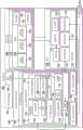
图1是采取根据例证性实施方式的框图的形式的制造环境的图示;1 is an illustration of a manufacturing environment in the form of a block diagram according to an illustrative embodiment;
图2是采取根据例证性实施方式的框图的形式的机身组件的图示;2 is an illustration of a fuselage assembly in the form of a block diagram according to an illustrative embodiment;
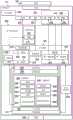
图3是采取根据例证性实施方式的框图的形式的制造环境内的柔性制造系统的多个移动系统的图示;3 is an illustration of a plurality of mobile systems of a flexible manufacturing system within a manufacturing environment in the form of a block diagram according to an illustrative embodiment;
图4是采取根据例证性实施方式的框图的形式的多个移动平台的图示;4 is an illustration of a plurality of mobile platforms in the form of a block diagram according to an illustrative embodiment;
图5是若干公用物(utility)横跨采取根据例证性实施方式的框图的形式的分布式公用物网络流动的图示;5 is an illustration of several utilities flowing across a distributed utility network in the form of a block diagram in accordance with an illustrative embodiment;
图6是采取根据例证性实施方式的框图的形式的外部移动平台;6 is an external mobile platform in the form of a block diagram according to an illustrative embodiment;
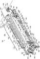
图7是根据例证性实施方式的制造环境的等距视图的图示;7 is an illustration of an isometric view of a manufacturing environment according to an illustrative embodiment;
图8是联接到根据例证性实施方式的公用物夹具的第一塔架的图示;8 is an illustration of a first tower coupled to a utility fixture according to an illustrative embodiment;
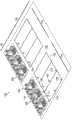
图9是根据例证性实施方式的支架系统的等距视图的图示;9 is an illustration of an isometric view of a stent system according to an illustrative embodiment;
图10是使用支架系统形成的且联接到根据例证性实施方式的第一塔架的组件夹具的等距视图的图示;10 is an illustration of an isometric view of an assembly clamp formed using a bracket system and coupled to a first tower in accordance with an illustrative embodiment;
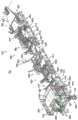
图11是用于建造机身组件的组装工艺的一个阶段的等距视图的图示,由根据例证性实施方式的组件夹具来支撑该机身组件;11 is an illustration of an isometric view of a stage of an assembly process for building a fuselage assembly supported by an assembly fixture in accordance with an illustrative embodiment;
图12是用于建造根据例证性实施方式的机身组件的组装工艺的另一阶段的等距视图的图示;12 is an illustration of an isometric view of another stage of an assembly process for building a fuselage assembly according to an illustrative embodiment;
图13是用于建造机身组件的组装工艺的另一阶段的等距视图的图示,由根据例证性实施方式的组件夹具来支撑该机身组件;13 is an illustration of an isometric view of another stage of an assembly process for building a fuselage assembly supported by an assembly clamp according to an illustrative embodiment;
图14是用于建造根据例证性实施方式的机身组件的组装工艺的另一阶段的等距视图的图示;14 is an illustration of an isometric view of another stage of an assembly process for building a fuselage assembly according to an illustrative embodiment;
图15是联接到公用物夹具以及支撑根据例证性实施方式的机身组件的组件夹具的第二塔架的等距视图的图示;15 is an illustration of an isometric view of a second tower coupled to a utility clamp and an assembly clamp supporting a fuselage assembly according to an illustrative embodiment;
图16是在根据例证性实施方式的机身组件的内部内执行紧固工艺的多个移动平台的等距剖视图的图示;16 is an illustration of an isometric cross-sectional view of multiple mobile platforms performing a fastening process within the interior of a fuselage assembly according to an illustrative embodiment;
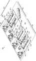
图17是在根据例证性实施方式的机身组件上执行操作的柔性制造系统的横截面图的图示;17 is an illustration of a cross-sectional view of a flexible manufacturing system performing operations on a fuselage assembly in accordance with an illustrative embodiment;
图18是根据例证性实施方式的完全建成的机身组件的等距视图的图示;18 is an illustration of an isometric view of a fully constructed fuselage assembly, according to an illustrative embodiment;
图19是在根据例证性实施方式的制造环境内建造的机身组件的等距视图的图示;19 is an illustration of an isometric view of a fuselage assembly constructed within a manufacturing environment in accordance with an illustrative embodiment;
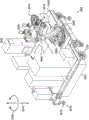
图20是根据例证性实施方式的外部移动平台的等距视图的图示;20 is an illustration of an isometric view of an external mobile platform according to an illustrative embodiment;
图21是根据例证性实施方式的平台基座的等距视图的图示;21 is an illustration of an isometric view of a platform base according to an illustrative embodiment;
图22是根据例证性实施方式的工具库站和末端执行器存储器的放大等距视图的图示;22 is an illustration of an enlarged isometric view of a tool magazine station and end effector storage according to an illustrative embodiment;
图23是根据例证性实施方式的外部移动平台的等距视图的图示;23 is an illustration of an isometric view of an external mobile platform according to an illustrative embodiment;
图24是根据例证性实施方式的外部移动平台的侧视图的图示;24 is an illustration of a side view of an external mobile platform according to an illustrative embodiment;
图25是根据例证性实施方式的外部移动平台的等距视图的图示;25 is an illustration of an isometric view of an external mobile platform according to an illustrative embodiment;
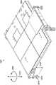
图26是相对于根据例证性实施方式的支撑结构处于不同位置的外部机器人装置的图示;26 is an illustration of an external robotic device in a different position relative to a support structure according to an illustrative embodiment;
图27是根据例证性实施方式的自主车辆的一部分的图示;27 is an illustration of a portion of an autonomous vehicle according to an illustrative embodiment;
图28是与根据例证性实施方式的自主车辆关联的传感器系统的放大视图的图示;28 is an illustration of an enlarged view of a sensor system associated with an autonomous vehicle in accordance with an illustrative embodiment;
图29是采取根据例证性实施方式的流程图的形式的用于执行组装操作的工艺的图示;29 is an illustration of a process for performing an assembly operation in the form of a flow diagram according to an illustrative embodiment;
图30是采取根据例证性实施方式的流程图的形式的用于执行组装操作的工艺的图示;30 is an illustration of a process for performing an assembly operation in the form of a flowchart according to an illustrative embodiment;
图31是采取根据例证性实施方式的流程图的形式的用于执行紧固工艺的工艺的图示;31 is an illustration of a process for performing a fastening process in the form of a flow diagram according to an illustrative embodiment;
图32是采取根据例证性实施方式的流程图的形式的用于执行紧固工艺的工艺的图示;32 is an illustration of a process for performing a fastening process in the form of a flow diagram according to an illustrative embodiment;
图33是采取根据例证性实施方式的框图的形式的数据处理系统的图示;33 is an illustration of a data processing system in the form of a block diagram according to an illustrative embodiment;
图34是采取根据例证性实施方式的框图的形式的飞行器制造及检修方法的图示;以及34 is an illustration of a method of manufacturing and servicing an aircraft in the form of a block diagram in accordance with an illustrative embodiment; and
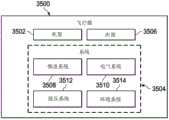
图35是采取可实施例证性实施方式的框图的形式的飞行器的图示。35 is an illustration of an aircraft in the form of a block diagram in which illustrative embodiments may be implemented.
具体实施方式Detailed ways
例证性实施方式认识并考虑到不同的考虑。例如,例证性实施方式认识并考虑到,可能期望使建造飞行器的机身组件的工艺自动化。使建造飞行器的机身组件的工艺自动化可提高建造效率、改进建造质量并且降低建造机身组件的相关成本。例证性实施方式还认识并考虑到,使建造机身组件的工艺自动化可提高执行组装操作的准确度和精确度,从而确保更好地遵守机身组件的外模线(OML)要求和内模线(IML)要求。The illustrative embodiments recognize and take into account different considerations. For example, the illustrative embodiments recognize and take into account that it may be desirable to automate the process of constructing fuselage components of an aircraft. Automating the process of constructing fuselage assemblies for aircraft can increase construction efficiency, improve build quality, and reduce the costs associated with constructing fuselage assemblies. The illustrative embodiments also recognize and take into account that automating the process of constructing airframe components may improve the accuracy and precision with which assembly operations are performed, thereby ensuring better compliance with the outer mold line (OML) requirements and inner molds of the airframe components. Line (IML) requirements.
此外,例证性实施方式认识并考虑到,用于建造飞行器的机身组件的工艺的自动化可显著减少建造周期所需要的时间量。例如,但不限于,使紧固操作自动化可减少并且在某些情况下消除为执行这些紧固操作以及其它类型的组装操作而对人工操作员的需要。Furthermore, the illustrative embodiments recognize and take into account that automation of the process for constructing fuselage components of an aircraft can significantly reduce the amount of time required for the construction cycle. For example, without limitation, automating fastening operations can reduce and in some cases eliminate the need for human operators to perform these fastening operations, as well as other types of assembly operations.
此外,相比于主要靠手动执行该工艺,这种类型的用于建造飞行器的机身组件的工艺的自动化可能劳动强度更低、耗时更少、人体工程学挑战更低并且更廉价。减少的手工劳动对于人工劳动者可具有期望的益处。另外,机身组装工艺的自动化可允许在期望的组装设施和工厂中以期望的组装率和期望的组装成本来建造机身组件。Furthermore, automation of this type of process for building fuselage components of an aircraft may be less labor-intensive, less time-consuming, less ergonomically challenging, and less expensive than performing the process primarily manually. The reduced manual labor can have desirable benefits for human laborers. Additionally, automation of the fuselage assembly process may allow fuselage assemblies to be built at desired assembly rates and at desired assembly costs in desired assembly facilities and factories.
例证性实施方式还认识并考虑到,可能期望使用可以被自主地驱动且操作以使建造机身组件的工艺自动化的器械。特别地,可能期望具有自主柔性制造系统,其包括这样的移动系统,该移动系统可在整个工厂地板上被自主地驱动,如建造机身组件所需要的相对于工厂地板被自主地定位,被自主地操作以建造机身组件,并且然后当机身组件的建造已经完成时被自主地驱离。The illustrative embodiments also recognize and take into account that it may be desirable to use instruments that can be driven and operated autonomously to automate the process of building airframe components. In particular, it may be desirable to have an autonomous flexible manufacturing system that includes a mobile system that can be driven autonomously throughout the factory floor, autonomously positioned relative to the factory floor as required to build fuselage assemblies, being Operates autonomously to build the fuselage assembly, and is then autonomously driven away when construction of the fuselage assembly has been completed.
如本文所使用的,自主地执行任何的操作、动作或步骤可能意味着在基本上没有任何人工输入的情况下执行此操作。例如,但不限于,可自主驱动的平台是可基本独立于任何人工输入被驱动的平台。以这种方式,可自主驱动平台可以是能够基本独立于人工输入而驱动或被驱动的平台。As used herein, performing any operation, action or step autonomously may mean performing the operation substantially without any human input. For example, without limitation, an autonomously drivable platform is one that can be driven substantially independently of any human input. In this manner, an autonomously drivable platform may be a platform capable of being driven or driven substantially independently of human input.
由此,例证性实施方式提供了用于建造飞行器的机身组件的方法、设备和系统。特别地,例证性实施方式提供了使建造机身组件的工艺的大部分(如果不是全部)自动化的自主柔性制造系统。例如,但不限于,自主柔性制造系统可使安装紧固件以将机身蒙皮面板和机身支撑结构结合到一起而建造机身组件的工艺自动化。Thus, the illustrative embodiments provide methods, apparatus, and systems for constructing fuselage assemblies of aircraft. In particular, the illustrative embodiments provide an autonomous flexible manufacturing system that automates most, if not all, of the process of building airframe assemblies. For example, but not limited to, autonomous flexible manufacturing systems may automate the process of installing fasteners to join fuselage skin panels and fuselage support structures together to build fuselage components.
然而,例证性实施方式认识并考虑到,使用自主柔性制造系统使建造机身组件的工艺自动化可能出现独特的技术挑战,即需要独特的技术方案。例如,例证性实施方式认识并考虑到,可能期望为自主柔性制造系统内的所有各种系统提供公用物。特别地,可能期望以将不会中断或延迟建造机身组件的工艺或者约束自主柔性制造系统内的各种移动系统在整个工厂地板的运动的方式来提供这些公用物。The illustrative embodiments, however, recognize and take into account that using autonomous flexible manufacturing systems to automate the process of building airframe components may present unique technical challenges that require unique technical solutions. For example, the illustrative embodiments recognize and take into account that it may be desirable to provide a commonality for all of the various systems within an autonomous flexible manufacturing system. In particular, it may be desirable to provide these utilities in a manner that will not interrupt or delay the process of building airframe assemblies or constrain the movement of various mobile systems within the autonomous flexible manufacturing system throughout the factory floor.
例如,但不限于,可能期望使用基础结构为自主柔性制造系统提供一组公用物,诸如电力、通信和空气,该基础结构仅包括与提供这一组公用物的一组公用物源的每各公用物源单个直接连接。这些直接连接可在地上、地面或地下。可使用例如(但不限于)公用物夹具来建立这些直接连接。由此,基础结构可包括:公用物夹具,该公用物夹具为一组公用物源的每个公用物源以及组装区域提供直接连接;该组装区域具有大到足够允许自主柔性制造系统的各种系统联接到公用物夹具且彼此串联的地板空间。以这种方式,这一组公用物可从这一组公用物源流向公用物夹具,然后向下游流向组装区域内的自主柔性制造系统的各种系统。For example, but not limited to, it may be desirable to provide an autonomous flexible manufacturing system with a set of utilities, such as power, communications, and air, using an infrastructure that includes only each component associated with a set of utility sources that provide the set of utilities Single direct connection to common provenance. These direct connections can be above, above or below ground. These direct connections may be established using, for example, but not limited to, utility clamps. Thus, the infrastructure may include: a utility fixture that provides a direct connection for each utility source of a set of utility sources and an assembly area; the assembly area having a variety of The system is coupled to the floor space of the utility fixture and in series with each other. In this manner, the set of utilities can flow from the set of utilities sources to the utility fixtures and then downstream to the various systems of the autonomous flexible manufacturing system within the assembly area.
由此,例证性实施方式提供了分布式公用物网络,其可用于为自主柔性制造系统的各种系统提供公用物。分布式公用物网络能以不约束或阻碍自主柔性制造系统的各种移动系统的运动的方式提供这些公用物。自主柔性制造系统的不同的移动系统可自主地彼此联接,以形成该分布式公用物网络。Thus, illustrative embodiments provide a distributed utility network that can be used to provide utilities for various systems of an autonomous flexible manufacturing system. A distributed utility network can provide these utilities in a manner that does not constrain or hinder the movement of the various mobile systems of the autonomous flexible manufacturing system. The different mobile systems of the autonomous flexible manufacturing system can be autonomously coupled to each other to form the distributed utility network.
现在参照附图,并且特别地参考图1-图5,采取根据例证性实施方式的框图的形式描绘了制造环境的图示。特别地,在图1-图5中,描述了机身组件、柔性制造系统、柔性制造系统内的可用于建造机身组件的各种系统以及分布式公用物网络。Referring now to the drawings, and in particular to FIGS. 1-5 , illustrations of a manufacturing environment are depicted in the form of block diagrams according to illustrative embodiments. In particular, in Figures 1-5, fuselage assemblies, a flexible manufacturing system, various systems within the flexible manufacturing system that can be used to build fuselage assemblies, and a distributed utility network are depicted.
现在转向图1,采取根据例证性实施方式的框图的形式描绘了制造环境的图示。在该例证性示例中,制造环境100可以是机身102的至少一部分可被制造用于飞行器104的一种环境的示例。Turning now to FIG. 1 , an illustration of a manufacturing environment is depicted in the form of a block diagram in accordance with an illustrative embodiment. In this illustrative example,
制造环境100可采取若干不同的形式。例如,但不限于,制造环境100可采取以下形式:工厂、制造设施、户外厂区、封闭的制造区域、海上平台或一些其它类型的适于建造机身102的至少一部分的制造环境100。
可使用制造工艺108来建造机身102。柔性制造系统106可用于实施制造工艺108的至少一部分。在一个例证性示例中,可使用柔性制造系统106使制造工艺108基本自动化。在其它例证性示例中,制造工艺108的仅一个或多个阶段可基本自动化。The
柔性制造系统106可构造成自主地执行制造工艺108的至少一部分。以这种方式,柔性制造系统106可称为自主柔性制造系统112。在其它例证性示例中,柔性制造系统106可称为自动化的柔性制造系统。The
如所描绘的,制造工艺108可包括用于建造机身组件114的组装工艺110。柔性制造系统106可构造成自主地执行组装工艺110的至少一部分。As depicted,
在完成制造工艺108之前在制造工艺108期间的任何阶段,机身组件114可以是机身102。在某些情况下,机身组件114可用来指部分组装的机身102。取决于实施方案,一个或多个其它部件可能需要附接至机身组件114,以全面完成机身102的组装。在其它情况下,机身组件114可用来指完全组装的机身102。柔性制造系统106可建造机身组件114,直到需要将机身组件114移向用于建造飞行器104的制造工艺的下一阶段的一点为止。在某些情况下,在用于建造飞行器104的制造工艺的一个或多个后期阶段可使用柔性制造系统106的至少一部分。
在一个例证性示例中,机身组件114可以是用于形成机身102的特定区段的组件。作为一个示例,机身组件114可采取用于形成机身102的后段的后机身组件116的形式。在另一示例中,机身组件114可采取用于形成机身102的前段的前机身组件117的形式。在又一示例中,机身组件114可采取中间机身组件118的形式,用于形成机身102的中央区段或位于机身102的后段和前段之间的机身102的一些其它中间段。In one illustrative example,
如所描绘的,机身组件114可包括多个面板120和支撑结构121。支撑结构121可包括多个构件122。多个构件122可用于既支撑多个面板120又将多个面板120彼此连接。支撑结构121可有助于为机身组件114提供强度、刚度和负载支撑。As depicted,
多个构件122可与多个面板120关联。如本文所使用的,当一个部件或结构与另一部件或结构“关联”时,所述关联在所描绘的示例中是物理关联。
例如,通过以下中的至少一者:即,固定到第二部件、粘接到第二部件、装设到第二部件、附接到部件、联接到部件、焊接到第二部件、紧固到第二部件、附着到第二部件、胶接到第二部件或以一些其它合适的方式连接到第二部件,第一部件(诸如多个构件122中的一个)可视为与第二部件(诸如多个面板120中的一个)关联。还可使用一个或多个其它部件将第一部件连接到第二部件。例如,可使用第三部件将第一部件连接到第二部件。此外,通过形成为第二部件的一部分、第二部件的延伸或两者,第一部件可视为与第二部件关联。在另一示例中,通过与第二部件共固化,第一部件可视为第二部件的一部分。For example, by at least one of: namely, securing to the second component, adhering to the second component, attaching to the second component, attaching to the component, coupling to the component, welding to the second component, securing to the second component The second component, attached to the second component, glued to the second component, or connected to the second component in some other suitable manner, the first component (such as one of the plurality of members 122 ) may be considered to be associated with the second component ( such as one of the plurality of panels 120) associated. One or more other components may also be used to connect the first component to the second component. For example, a third part may be used to connect the first part to the second part. Furthermore, the first component may be considered to be associated with the second component by being formed as part of the second component, an extension of the second component, or both. In another example, the first part may be considered part of the second part by co-curing with the second part.
如本文所使用的,短语“(中的)至少一个/至少一者”当与一列项目使用时,意指可使用所列项目中的一个或多个的不同组合并且可能仅需要列中的一个项目。所述项目可以是特定的对象、事物、动作、工艺或类别。换句话说,“(中的)至少一个/至少一者”意指可使用列中的项目或项目数量的任何组合,但可能并不需要列中的所有项目。As used herein, the phrase "at least one/at least one of" when used with a list of items means that different combinations of one or more of the listed items may be used and that only one of the list may be required project. The item may be a specific object, thing, action, craft or category. In other words, "(of) at least one/at least one of" means that any combination of items or numbers of items in a column may be used, although not all of the items in a column may be required.
例如,“项目A、项目B和项目C中的至少一个”或“项目A、项目B或项目C中的至少一个”可能意味着:项目A;项目A和项目B;项目B;项目A、项目B和项目C;或项目B和项目C。在某些情况下,“项目A、项目B和项目C中的至少一个”可能意味着例如(但不限于):两个项目A、一个项目B和十个项目C;四个项目B和七个项目C;或一些其它合适的组合。For example, "at least one of item A, item B, and item C" or "at least one of item A, item B, or item C" might mean: item A; item A and item B; item B; item A, Item B and Item C; or Item B and Item C. In some cases, "at least one of Item A, Item B, and Item C" may mean, for example (but not limited to): two Item A, one Item B, and ten Item C; four Item B and seven item C; or some other suitable combination.
在这些例证性示例中,多个构件122的一构件能以若干不同的方式与多个面板120中的至少一个关联。例如,但不限于,多个构件122的一构件可直接附接至单个面板,附接至两个或更多个面板,附接至直接附接至至少一个面板的另一构件,附接至直接或间接附接至至少一个面板的至少一个构件,或者以一些其它方式与多个面板120中的至少一个关联。In these illustrative examples, a member of plurality of
在一个例证性示例中,在开始用于建造机身组件114的组装工艺110之前,基本所有或所有的多个构件122可与多个面板120关联。例如,在多个面板120彼此经由组装工艺110而结合之前,多个构件122的相应部分可与多个面板120的每个面板关联。In one illustrative example, substantially all or all of plurality of
在另一例证性示例中,在开始组装工艺110之前,仅多个构件122的第一部分可与多个面板120关联。组装工艺110可包括将多个构件122的剩余部分附接至多个面板120,至少用于为多个面板120提供支撑或者将多个面板120连接到一起中的一者。多个构件122的在组装工艺110之前附接至多个面板120的第一部分以及多个构件122的在组装工艺110期间附接至多个面板120的剩余部分可一起形成支撑结构121。In another illustrative example, only a first portion of plurality of
在又一例证性示例中,在组装工艺110期间,所有的多个构件122可与多个面板120关联。例如,在组装工艺110之前,多个面板120均可“裸露”,无需任何构件附接至面板或以其它的方式与面板关联。在组装工艺110期间,多个构件122然后可与多个面板120关联。In yet another illustrative example, all of plurality of
以这种方式,用于机身组件114的支撑结构121能以若干不同的方式建造起来。在下面的图2中更详细地描述包括多个面板120和支撑结构121的机身组件114。In this manner, the
建造机身组件114可包括将多个面板120结合到一起。能以若干不同的方式执行结合多个面板120。取决于实施方案,将多个面板120结合到一起可包括将多个构件122中的一个或多个结合到多个面板120中的一个或多个或者结合到多个构件122的其它构件。Building the
特别地,结合多个面板120可包括:将至少一个面板结合到至少一个其它面板,将至少一个构件结合到至少一个其它构件,或者将至少一个构件结合到至少一个面板,或者它们的一些组合。作为一个例证性示例,将第一面板和第二面板结合到一起可包括以下中的至少一个:将第一面板直接紧固到第二面板,将与第一面板关联的第一构件结合到与第二面板关联的第二构件,将与第一面板关联的构件直接结合到第二面板,将与第一面板和第二面板两者均关联的一个构件结合到另一构件,将选定构件结合到第一面板和第二面板两者,或者一些其它类型的结合操作。In particular, joining the plurality of
组装工艺110可包括操作124,可执行操作124将多个面板120结合到一起以建造机身组件114。在该例证性示例中,可使用柔性制造系统106来自主地执行操作124的至少一部分。The
操作124可包括例如(但不限于):临时连接操作125、钻孔操作126、紧固件插入操作128、紧固件安装操作130、检查操作132、其它类型的组装操作或这些操作的一些组合。可执行临时连接操作125以将多个面板120临时连接到一起。例如,但不限于,临时连接操作125可包括使用钉紧固件将多个面板120临时钉接到一起。
钻孔操作126可包括:钻孔穿过多个面板120的一个或多个,在某些情况下,钻孔穿过多个构件122的一个或多个。紧固件插入操作128可包括将紧固件插入由钻孔操作126钻出的孔中。
紧固件安装操作130可包括完全安装已插入孔中的每个紧固件。紧固件安装操作130可包括例如(但不限于)铆接操作、过盈配合栓接操作、其它类型的紧固件安装操作或这些操作的一些组合。检查操作132可包括检查完全安装的紧固件。取决于实施方案,柔性制造系统106可用于基本自主地执行任何数量的这些不同类型的操作124。
如所描绘的,柔性制造系统106可包括多个移动系统134、控制系统136和公用物系统138。多个移动系统134均可以是可驱动的移动系统。在某些情况下,多个移动系统134均可以是可自主驱动的移动系统。例如,但不限于,多个移动系统134均可包括可在制造环境100内从一个地点被自主地驱动到另一地点的一个或多个部件。在下面的图3中更详细地描述多个移动系统134。As depicted, the
在该例证性示例中,控制系统136可用于控制柔性制造系统106的操作。例如,但不限于,控制系统136可用于控制多个移动系统134。特别地,控制系统136可用于引导多个移动系统134中的每个在制造环境100内的运动。控制系统136可至少部分地与多个移动系统134关联。In this illustrative example,
在一个例证性示例中,控制系统136可包括一组控制器140。如本文所使用的,“一组”项目可包括一个或多个项目。以这种方式,一组控制器140可包括一个或多个控制器。In one illustrative example,
一组控制器140均可使用硬件、固件、软件或它们的一些组合来实施。在一个例证性示例中,一组控制器140可与多个移动系统134关联。例如,但不限于,一组控制器140中的一个或多个可实施为多个移动系统134的一部分。在其它示例中,一组控制器140中的一个或多个可独立于多个移动系统134来实施。A set of controllers 140 can each be implemented using hardware, firmware, software, or some combination thereof. In one illustrative example, a set of controllers 140 may be associated with multiple
一组控制器140可生成命令142,以控制柔性制造系统106的多个移动系统134的操作。一组控制器140可使用无线通信链路、有线通信链路、光通信链路或其它类型的通信链路中的至少一个与多个移动系统134通信。以这种方式,任何数量的不同类型的通信链路可用于与一组控制器140通信以及在一组控制器140之间通信。A set of controllers 140 may generate
在这些例证性示例中,控制系统136可使用从传感器系统133接收的数据141来控制多个移动系统134的操作。传感器系统133可包括任何数量的单独的传感器系统、传感器装置、控制器、其它类型的部件或它们的组合。在一个例证性示例中,传感器系统133可包括激光跟踪系统135和雷达系统137。激光跟踪系统135可包括任何数量的激光跟踪装置、激光目标或它们的组合。雷达系统137可包括任何数量的雷达传感器、雷达目标或他们的组合。In these illustrative examples,
传感器系统133可用于协调多个移动系统134中的各种移动系统在制造环境100内的运动和操作。作为一个例证性示例,雷达系统137可用于移动系统、移动系统内的系统、移动系统内的部件或它们的一些组合的宏观定位。此外,激光跟踪系统135可用于移动系统、移动系统内的系统、移动系统内的部件或它们的一些组合的微定位。
多个移动系统134可用于形成分布式公用物网络144。取决于实施方案,多个移动系统134中的一个或多个可形成分布式公用物网络144。若干公用物146可从若干公用物源148流向组成分布式公用物网络144的多个移动系统134的各种移动系统。A plurality of
在该例证性示例中,若干公用物源148均可位于制造环境100内。在其它例证性示例中,若干公用物源148中的一个或多个可位于制造环境100的外侧。由这一个或多个公用物源提供的相应的公用物然后可使用例如(但不限于)一个或多个公用物线缆被运载到制造环境100中。In this illustrative example, several
在一个例证性示例中,分布式公用物网络144可允许若干公用物146经由若干公用物线缆而直接从若干公用物源148流向多个移动系统134的一个移动系统。该一个移动系统然后可将若干公用物146分配给多个移动系统134的其它移动系统,使得这些其它移动系统不需要直接接收来自若干公用物源148的若干公用物146。In one illustrative example, distributed
如所描绘的,可使用公用物系统138而形成分布式公用物网络144。公用物系统138可包括公用物夹具150。公用物系统138可构造成连接到若干公用物源148,使得若干公用物146可从若干公用物源148流向公用物夹具150。取决于实施方案,公用物夹具150可在地上或地面中。例如,但不限于,公用物夹具150可嵌入在制造环境100内的地板中。As depicted, a distributed
公用物夹具150然后可将若干公用物146分配给多个移动系统134中的一个或多个。特别地,多个移动系统134之一到公用物夹具150的一种自主联接之后可以是任何数量的移动系统彼此串联的自主联接,以形成分布式公用物网络144。公用物夹具150可在移动系统的自主联接的串联中的公用物夹具150的下游将若干公用物146分配给多个移动系统134中的每个。The
取决于实施方案,分布式公用物网络144可具有链状构造或树状构造。在一个例证性示例中,多个移动系统134可包括移动系统A、B、C和D(在图中未示出),移动系统A自主地联接到公用物夹具150并且移动系统B、C和D自主地联接到移动系统A且彼此串联。用于分布式公用物网络144的链状构造的示例可包括若干公用物146,若干公用物146从若干公用物源148经由若干公用物线缆流向公用物夹具150,从公用物夹具150流向移动系统A,从移动系统A流向移动系统B,从移动系统B流向移动系统C,以及从移动系统C流向移动系统D。用于分布式公用物网络144的树状构造的示例可包括若干公用物146,若干公用物146从若干公用物源148经由若干公用物线缆流向公用物夹具150,从公用物夹具150流向移动系统A,从移动系统A流向移动系统B和移动系统C两者,以及从移动系统C流向移动系统D。在下面的图5中更详细地描述了可使用多个移动系统134来实施分布式公用物网络144的一种方式的示例。Depending on the implementation, the distributed
在一些例证性示例中,多个柔性制造系统可用于同时建造多个机身组件。例如,柔性制造系统106可以是许多柔性制造系统中的第一柔性制造系统。In some illustrative examples, multiple flexible manufacturing systems may be used to construct multiple airframe assemblies simultaneously. For example,
在一个例证性示例中,柔性制造系统106、第二柔性制造系统152和第三柔性制造系统154可分别用于建造后机身组件116、中间机身组件118和前机身组件117。后机身组件116、中间机身组件118和前机身组件117然后可结合到一起,以形成完全组装的机身102。以这种方式,在该示例中,柔性制造系统106、第二柔性制造系统152和第三柔性制造系统154可一起形成柔性机身制造系统158。In one illustrative example,
由此,可使用以类似于柔性制造系统106的方式实施的任何数量的柔性制造系统在制造环境100内建造任何数量的机身组件(诸如机身组件114)。类似地,可使用任何数量的以类似于柔性机身制造系统158的方式实施的柔性机身制造系统在制造环境100内建造任何数量的完全的机身(诸如机身102)。As such, any number of fuselage components, such as
现在参考图2,采取根据例证性实施方式的框图的形式来描绘图1的机身组件114的图示。如上文所描述的,机身组件114可包括多个面板120和支撑结构121。机身组件114可用来指建造机身组件114的任何阶段。例如,机身组件114可用来指多个面板120中的单个面板、多个面板120中的已经或正被结合到一起的多个面板、部分建造的机身组件或完全建成的机身组件。Referring now to FIG. 2 , an illustration of the
如所描绘的,机身组件114可被建造成使得机身组件114具有多个机身区段205。多个机身区段205均可包括多个面板120中的一个或多个。在该例证性示例中,多个机身区段205均可采取柱形机身区段、桶形机身区段、渐缩柱形机身区段、锥形机身区段、拱形机身区段或具有一些其它类型的形状的区段的形式。取决于实施方案,多个机身区段205中的机身区段可具有如下形状:基本圆形横截面形状、椭圆横截面形状、卵形横截面形状、带圆角的多边形横截面形状或以其它的方式呈闭合曲线的横截面形状。As depicted,
作为一个具体例证性示例,多个机身区段205均可以是机身组件114的限定在基本垂直于中心轴线或穿过机身组件114的纵向轴线截取的机身组件114的两个径向横截面之间的部分。以这种方式,可沿着机身组件114的纵向轴线来布置多个机身区段205。换句话说,可纵向地布置多个机身区段205。As a specific illustrative example, each of the plurality of
机身区段207可以是多个机身区段205之一的示例。机身区段207可包括多个面板120中的一个或多个。在一个例证性示例中,可围绕机身区段207沿圆周来布置多个面板区段,以形成机身区段207的蒙皮。在某些情况下,可围绕机身区段207沿圆周来布置多排的两个或更多个纵向相邻面板,以形成机身区段207的蒙皮。
在一个例证性示例中,机身组件114可具有机顶200、龙骨202和侧面204。侧面204可包括第一侧面206和第二侧面208。In one illustrative example,
机顶200可以是机身组件114的顶部。龙骨202可以是机身组件114的底部。机身组件114的侧面204可以是机身组件114在机顶200和龙骨202之间的部分。在一个例证性示例中,机身组件114的机顶200、龙骨202、第一侧面206和第二侧面208均可由多个面板120的至少一个面板的至少一部分形成。此外,多个机身区段205的每个的一部分可形成机顶200、龙骨202、第一侧面206和第二侧面208中的每个。Set top 200 may be the top of
面板216可以是多个面板120之一的示例。取决于实施方案,面板216还可称为蒙皮面板、机身面板或机身蒙皮面板。在一些例证性示例中,面板216可采取包括多个较小面板(这可称为子面板)的大型面板的形式。大型面板还可称为超级面板。在这些例证性示例中,面板216可包括金属、金属合金、一些其它类型的金属材料、复合材料或一些其它类型的材料中的至少一者。作为一个例证性示例,面板216可包括铝合金、钢、钛、陶瓷材料、复合材料、一些其它类型的材料或它们的一些组合。
当用于形成机身组件114的龙骨202时,面板216可称为龙骨面板或底面板。当用于形成机身组件114的侧面204之一时,面板216可称为侧面板。当用于形成机身组件114的机顶200时,面板216可称为机顶面板或顶面板。作为一个例证性示例,多个面板120可包括用于形成机顶200的机顶面板218、用于形成侧面204的侧面板220以及用于形成龙骨202的龙骨面板222。侧面板220可包括用于形成第一侧面206的第一侧面板224以及用于形成第二侧面208的第二侧面板226。When used to form the
在一个例证性示例中,机身组件114的多个机身区段205的机身区段207可包括一个机顶面板218、两个侧面板220以及一个龙骨面板222。在另一例证性示例中,机身区段207可形成机身组件114的端部。In one illustrative example,
在某些情况下,机身区段207可仅仅包括单个面板,诸如面板216。例如,但不限于,面板216可采取端面板228的形式。In some cases,
端面板228可用于形成机身组件114的一端。例如,当机身组件114采取图1中的后机身组件116的形式时,端面板228可形成机身组件114的最后端。当机身组件114采取图1中的前机身组件117的形式时,端面板228可形成机身组件114的最前端。An
在一个例证性示例中,端面板228可采取柱形面板、锥形面板、桶形面板或渐缩柱形面板的形式。例如,端面板228可以是具有直径关于机身组件114的中心轴线可改变的基本圆形横截面形状的单个柱形面板。In one illustrative example, end
以这种方式,如上文所描述的,机身区段207可独自包括端面板228。在一些例证性示例中,机身区段207可以是仅包括单个面板(其可以是端面板228)的末端机身区段。在某些情况下,当机身区段207是末端机身区段时,隔框(bulkhead)272可与端面板228关联。取决于实施方案,隔框272(其还可称为压力隔框)可视为与端面板228分离或者视为端面板228的一部分。在这些例证性示例中,隔框272可具有拱型形状。In this manner,
当机身组件114采取图1中的后机身组件116的形式时,隔框272可以是机身区段207的位于后机身组件116的最后端处的部分。当机身组件114采取图1中的前机身组件117的形式时,隔框272可以是机身区段207的位于后机身组件116的最前端处的部分。图1中的中间机身组件118在中间机身组件118的任一端处可不包括隔框,诸如隔框272。以这种方式,能以任何数量的不同方式来实施多个机身区段205。When
面板216可具有第一表面230和第二表面232。第一表面230可构造成用作面向外部的表面。换句话说,第一表面230可用于形成机身组件114的外部234。第二表面232可构造成用作面向内部的表面。换句话说,第二表面232可用于形成机身组件114的内部236。多个面板120均能以类似于面板216的方式来实施。The
如此前所描述的,支撑结构121可与多个面板120的相应面板关联。支撑结构121可包括与面板216关联的多个构件122。在一个例证性示例中,相应部分240可以是对应于面板216的多个构件122的部分。相应部分240可形成对应于面板216的支撑区段238。支撑区段238可形成支撑结构121的一部分。As previously described, the
多个构件122可包括支撑构件242。支撑构件242可包括例如(但不限于)连接构件244、框架246、纵梁248、加强筋250、支柱252、肋间结构构件254或其它类型的结构构件中的至少一者。The plurality of
连接构件244可将其它类型的支撑构件242连接到一起。在某些情况下,连接构件244还可将支撑构件242连接到多个面板120。连接构件244可包括例如(但不限于)剪切夹256、系材258、拼接件260、肋间连接构件262、其它类型的机械连接构件或它们的一些组合。The connecting members 244 may connect other types of support members 242 together. In some cases, the connecting members 244 may also connect the support members 242 to the plurality of
在一个例证性示例中,当面板216包括多个子面板时,连接构件244可用于例如(但不限于)将框架246的在相邻子面板上的环箍方向上延伸的互补框架和纵梁248的在相邻子面板上的纵向方向上延伸的互补纵梁连接到一起。在其它例证性示例中,连接构件244可用于将多个面板120中的两个或更多个相邻面板上的互补框架、纵梁或其它类型的支撑构件连接到一起。在某些情况下,连接构件244可用于将两个或更多个相邻机身区段上的互补支撑构件连接到一起。In one illustrative example, when
可执行如图1中描述的操作124,以将多个面板120结合到一起来建造机身组件114。在一个例证性示例中,多个紧固件264可用于将多个面板120结合到一起。
如上文所描述的,能以若干不同的方式来执行将多个面板120结合到一起。将多个面板120结合到一起可包括以下手段中的至少一者:将多个面板120中的至少一个面板结合到多个面板120中的另一面板,将多个面板120中的至少一个面板结合到多个构件122中的至少一个构件,将多个构件122中的至少一个构件结合到多个构件122中的另一构件,或者一些其它类型的结合操作。多个面板120可结合到一起,使得多个构件122最终形成用于机身组件114的支撑结构121。As described above, joining the plurality of
如所描绘的,若干地板266可与机身组件114关联。在该例证性示例中,若干地板266可以是机身组件114的一部分。若干地板266可包括例如(但不限于)乘客地板、货舱地板或一些其它类型的地板中的至少一个。As depicted, number of
现在参考图3,采取根据例证性实施方式的框图的形式描绘了在图1的制造环境100内的柔性制造系统106的多个移动系统134的图示。如所描绘的,柔性制造系统106可用于在制造环境100的地板300上建造机身组件114。当制造环境100采取工厂的形式时,地板300可称为工厂地板302。Referring now to FIG. 3 , an illustration of a plurality of
在一个例证性示例中,地板300可以是基本平滑且基本平坦的。例如,地板300可以是基本水平的。在其它例证性示例中,地板300的一个或多个部分可以是倾斜的、带斜面的或者其他不平坦的。In one illustrative example,
组装区域304可以是在制造环境100内指定用于执行图1的用于建造机身组件(诸如机身组件114)的组装工艺110的区域。组装区域304还可称为隔间或工作隔间。在该例证性示例中,组装区域304可以是地板300上的指定区域。然而,在其它例证性示例中,组装区域304可包括地板300上的指定区域以及该指定区域上方的区域。任何数量的组装区域可存在于制造环境100内,使得可在制造环境100内同时建造任何数量的机身组件。
如所描绘的,多个移动系统134可包括多个自主车辆306、支架系统308、塔架系统310和自主加工系统312。多个移动系统134均可横跨地板300而可被驱动。换句话说,多个移动系统134均能够被自主地驱动,横跨地板300从地板300上的一个地点315到达另一地点317。As depicted, number of
在一个例证性示例中,多个自主车辆306均可采取自动导向车辆(AGV)的形式,自动导向车辆能够独立地操作而无需人工引导或导向。在某些情况下,多个自主车辆306可被称为多个自动导向车辆(AGV)。In one illustrative example, multiple
在该例证性示例中,在图1的组装工艺110期间,支架系统308可用于支撑并保持机身组件114。在某些情况下,支架系统308可称为可驱动式支架系统。在还有其它的情况下,支架系统308可称为可自主驱动式支架系统。In this illustrative example,
支架系统308可包括若干夹具313。如本文所使用的,“若干”项目可包括一个或多个项目。以这种方式,若干夹具313可包括一个或多个夹具。在一些例证性示例中,若干夹具313可称为若干可驱动式夹具。在其它例证性示例中,若干夹具313可称为若干可自主驱动式夹具。The
若干夹具313可包括若干支架夹具314。在一些例证性示例中,若干支架夹具314可称为若干可驱动式支架夹具。在其它例证性示例中,若干支架夹具314可称为若干可自主驱动式支架夹具。支架夹具322可以是若干支架夹具314之一的示例。Number of
若干保持结构326可与若干支架夹具314的每个关联。与若干支架夹具314的每个关联的若干保持结构326可与机身组件114接合并用于支撑机身组件114。例如,与支架夹具322关联的若干保持结构326可与多个面板120中的一个或多个接合并用于支撑多个面板120中的一个或多个。Number of
若干支架夹具314可横跨制造环境100的地板300被自主地驱动到组装区域304。在一个例证性示例中,若干支架夹具314均可使用多个自主车辆306的相应自主车辆横跨地板300被自主地驱动。换句话说,并不限于,多个自主车辆306中的若干相应自主车辆316可用于横跨地板300将若干支架夹具314驱动到组装区域304中。Number of rack clamps 314 may be autonomously driven to
在该例证性示例中,若干相应自主车辆316可从例如(但不限于)贮存区域318横跨地板300而驱动到组装区域304。贮存区域318可以是这样的区域:当柔性制造系统106未被使用时或者当此特定装置或系统未被使用时,在该区域中可贮存多个自主车辆306、支架系统308、塔架系统310、自主加工系统312或图1的控制系统136中的至少一个。In this illustrative example, several respective
取决于实施方案,贮存区域318可称为家区域、存储区域或基地区域。虽然贮存区域318被描绘为位于制造环境100内,但在其它例证性示例中,贮存区域318也可位于制造环境100外侧的一些其它区域或环境中。Depending on the implementation, the
多个自主车辆306中的若干相应自主车辆316可将若干支架夹具314驱动到若干选定支架位置320。如本文所使用的,“位置(position)”可包括地点(location)、取向或两者。所述地点可关于参考坐标系处于二维坐标或三维坐标上。所述取向可以是关于参考坐标系的二维或三维取向。该参考坐标系可例如(但不限于)是机身坐标系、飞行器坐标系、针对制造环境100的坐标系或一些其它类型的坐标系。A number of respective
当若干支架夹具314包括多于一个支架夹具而使得若干选定支架位置320包括多于一个支架位置时,这些支架位置可以是相对于彼此选择的位置。以这种方式,若干支架夹具314可被定位成使得若干支架夹具314相对于彼此处于若干选定支架位置320中。When number of rack clamps 314 includes more than one rack clamp such that number of selected
在这些例证性示例中,若干相应自主车辆316可用于在组装区域304内将若干支架夹具314驱动到若干选定支架位置320中。横跨地板300来“驱动”部件或系统可能意味着,例如(但不限于),基本将此部件或系统的整体从一个地点移向另一地点。例如,但不限于,横跨地板300来驱动支架夹具322可能意味着将支架夹具322的整体从一个地点移向另一地点。换句话说,所有或基本所有的包括支架夹具322的部件可同时一起从一个地点移向另一地点。In these illustrative examples, number of respective
一旦若干支架夹具314已被驱动到组装区域304中的若干选定支架位置320之中,若干支架夹具314就可彼此联接并联接到塔架系统310。一旦在选定的公差内将若干支架夹具314定位在若干选定支架位置320中,若干相应自主车辆316于是就可远离若干支架夹具314驱动到例如(但不限于)贮存区域318。在其它例证性示例中,若干相应自主车辆316可包括单个自主车辆,该单个自主车辆用于一次一个地在组装区域304内将若干支架夹具314的每个驱动到若干选定支架位置320的相应选定位置中。Once the number of bracket clamps 314 has been driven into the number of selected
在组装区域304中,若干支架夹具314可构造成形成组件夹具324。当若干支架夹具314中的不同支架夹具已经相对于彼此放置在若干选定支架位置320中时,可形成组件夹具324。在某些情况下,当若干支架夹具314已经彼此联接同时若干支架夹具314处于若干选定支架位置320中时,以及当与若干支架夹具314的每个关联的若干保持结构326已被调整而接收机身组件114时,可形成组件夹具324。In
以这种方式,若干支架夹具314可形成单个夹具实体,诸如组件夹具324。组件夹具324可用于支撑并保持机身组件114。在某些情况下,组件夹具324可称为组件夹具系统或夹具系统。在某些情况下,组件夹具324可称为可驱动式组件夹具。在其它情况下,组件夹具324可称为可自主驱动式组件夹具。In this manner, several bracket clamps 314 may form a single clamp entity, such as
一旦已经形成组件夹具324,若干支架夹具314就可接收机身组件114。换句话说,多个机身区段205可与若干支架夹具314接合。特别地,多个机身区段205可与若干保持结构326接合,若干保持结构326与若干支架夹具314的每个关联。多个机身区段205能以任何数量的方式与若干支架夹具314接合。Once the assembly clamps 324 have been formed, the number of bracket clamps 314 can receive the
当若干支架夹具314包括单个支架夹具时,此支架夹具可用于支撑并保持基本整个机身组件114。当若干支架夹具314包括多个支架夹具时,这些支架夹具均可用于支撑并保持多个机身区段205的至少一个相应机身区段。When the number of bracket clips 314 includes a single bracket clip, this bracket clip can be used to support and hold substantially the
在一个例证性示例中,多个机身区段205均可一次一个与若干支架夹具314接合。例如,但不限于,用于多个机身区段205中的特定机身区段的所有面板可相对于彼此以及若干支架夹具314的相应支架夹具进行定位,然后与相应支架夹具接合。多个机身区段205的剩余机身区段然后可形成并以类似的方式与若干支架夹具314接合。以这种方式,通过使多个面板120的至少一部分与组成组件夹具324的若干支架夹具314的每个关联的若干保持结构326接合,使得多个面板120由若干支架夹具314支撑,使得多个面板120可与若干支架夹具314接合。In one illustrative example,
如图2中描述的,多个面板120可包括龙骨面板222、侧面板220和机顶面板218。在一个例证性示例中,所有的图2中的龙骨面板222用于形成图2中的机身组件114的龙骨202,龙骨面板222可首先相对于若干支架夹具314进行定位并与若干支架夹具314接合。接着,所有的图2中的侧面板220用于形成图2中的机身组件114的侧面204,侧面板220可相对于龙骨面板222进行定位并与龙骨面板222接合。然后,所有的图2中的机顶面板218用于形成图2中的机身组件114的机顶200,机顶面板218可相对于侧面板220进行定位并与侧面板220接合。以这种方式,多个机身区段205可同时组装,以形成机身组件114。As depicted in FIG. 2 , the plurality of
在一个例证性示例中,多个面板120中的每个面板均可具有多个构件122的在面板与若干支架夹具314之一接合之前完全形成并与面板关联的相应部分。多个构件122的该相应部分可称为支撑区段。例如,在面板216与若干支架夹具314之一或图2中的多个面板120的另一面板接合之前,图2中的支撑区段238可完全形成并与图2中的面板216关联。换句话说,在图2的面板216与若干支架夹具314之一接合之前,图2中的支撑构件242的相应部分已经可附接至面板216,并且图2中的连接构件244的相应部分已经被安装成使支撑构件242的该部分彼此连接。In one illustrative example, each of the plurality of
在其它例证性示例中,在多个面板120已经彼此接合并与若干支架夹具314接合之后,多个构件122可与多个面板120关联。在其它例证性示例中,在多个面板120彼此接合并与若干支架夹具314接合之前,多个构件122的仅一部分可与多个面板120关联,然后一旦多个面板120已经彼此接合并与若干支架夹具314接合,多个构件122的剩余部分就与多个面板120关联。In other illustrative examples,
在一些例证性示例中,当图2的面板216与若干支架夹具314之一或与多个面板120的其它面板之一接合时,图2中的一个或多个支撑构件242、图2中的一个或多个连接构件244或两者可不与面板216关联。例如,但不限于,在面板216已经与支架夹具322接合之后,图2中描述的框架246可加装到图2的面板216。在另一示例中,在面板216已经与支架夹具322接合之后,图2中描述的加强筋250可加装到图2的面板216。In some illustrative examples, one or more support members 242 in FIG. 2 , one or more support members 242 in FIG. 2 , one or more support members 242 in FIG. One or more of the connecting members 244 or both may not be associated with the
建造机身组件114可包括:随着多个面板120在组件夹具324的若干支架夹具314上建造起来,使多个面板120彼此接合。例如,通过至少连接支撑构件的与面板关联的部分,可连接多个面板120中的相邻面板。取决于实施方案,搭接拼接件、对接拼接件或其它类型的拼接件中的至少一者可用于连接相邻面板(除了或代替连接相邻面板的相应支撑构件)。Building the
作为一个例证性示例,与多个面板120中的两个相邻面板关联的支撑构件可使用连接构件而连接到一起,从而连接了两个相邻面板。与这两个相邻面板关联的两个支撑构件可例如(但不限于)以拼接、捆绑、夹持、钉接、销接、结合或一些其它的方式被紧固到一起。当两个相邻面板沿环箍相邻时,可在环箍方向上连接互补框架。当两个相邻面板沿纵向相邻时,可在纵向方向上连接互补纵梁。As an illustrative example, support members associated with two adjacent panels of the plurality of
在某些情况下,在这两个相邻面板上连接互补的纵梁、框架或其它支撑构件可成为将这些面板拼接到一起的一部分。相邻面板可使用任何数量的面板拼接件、纵梁拼接件、框架拼接件或其它类型的拼接件而连接到一起。In some cases, connecting complementary stringers, frames or other support members on the two adjacent panels may be part of splicing the panels together. Adjacent panels may be joined together using any number of panel splices, stringer splices, frame splices, or other types of splices.
在一个例证性示例中,通过使用临时紧固件或永久紧固件将多个面板120或多个构件122中的至少一者临时地紧固到一起而使得多个面板120可临时地彼此连接。例如,但不限于,临时夹钳可用于将多个面板120中的两个面板一起临时地连接并保持到位。可通过以下手段中的至少一者来执行将多个面板120临时地连接到一起:将至少两个多个面板120临时地连接到一起,将至少两个多个构件122临时地连接到一起,或者将多个面板120中的至少一个临时地连接到多个构件122中的至少一个,使得与多个面板120关联的多个构件122形成了图2中用于机身组件114的支撑结构121。In one illustrative example, the plurality of
作为一个例证性示例,可使用临时紧固件328将多个面板120临时地钉接或销接到一起,直到多个紧固件264被安装成将多个面板120结合到一起以形成机身组件114。临时地连接多个面板120可将图2由多个面板120形成的多个机身区段205临时地连接到一起。一旦多个紧固件264已安装好,然后就可拆除临时紧固件328。As an illustrative example, the plurality of
以这种方式,多个面板120能以若干不同的方式连接到一起。一旦多个面板120已经连接到一起,多个构件122就可视为形成了用于机身组件114的支撑结构121。将多个面板120连接到一起以及形成支撑结构121可保持期望地遵守机身组件114的外模线要求和内模线要求。换句话说,多个面板120可相对于彼此在一起保持到位,使得使用多个面板120而形成的机身组件114在选定的公差内满足机身组件114的外模线要求和内模线要求。In this manner,
特别地,组件夹具324可支撑多个面板120以及与多个面板120关联的支撑结构121,使得使用多个面板120和支撑结构121而建造的机身组件114具有选定公差内的形状和构造。以这种方式,该形状和构造可维持在选定的公差内,同时在建造机身组件114期间支撑着多个面板120以及与多个面板120关联的多个构件122。可至少部分地由例如(但不限于)机身组件114的外模线要求和内模线要求来确定该形状。在某些情况下,可至少部分地由机身组件114的框架和纵梁的地点和取向来确定该形状。In particular, the
在某些情况下,当多个面板120和支撑结构121的包括机身组件114的组件已到达期望点时,若干相应自主车辆316可将组件夹具324驱动至组装区域304的外部。例如,机身组件114可横跨地板300被驱动到制造环境100内的不同区域中,从地板300驱动到不同制造环境的另一地板上,或者从地板300驱动到一些其它区域或环境的另一地板上。In some cases, when the assembly of the plurality of
在一个例证性示例中,组件夹具324可被驱动到另一组件夹具所位于的一些其它地点,使得两个组件夹具可联接而形成更大的组件夹具。作为一个例证性示例,组件夹具324可用于保持并支撑图1中的后机身组件116,而以类似于组件夹具324的方式实施的另一组件夹具可用于保持并支撑图1中的前机身组件117。以类似于组件夹具324的方式实施的又一组件夹具可用于保持并支撑图1中的中间机身组件118。In one illustrative example,
一旦这三个机身组件已经建造完毕,三个组件夹具就可被带到一起以形成更大的组件夹具来保持后机身组件116、中间机身组件118和前机身组件117,使得这三个机身组件可被结合以形成图1中描述的机身102。特别地,这个更大的组件夹具可保持后机身组件116、中间机身组件118和前机身组件117彼此对准,使得可在选定的公差内建造机身102。Once the three fuselage assemblies have been constructed, the three assembly jigs can be brought together to form a larger assembly jig to hold the
在另一例证性示例中,以类似于组件夹具324的方式实施的第一组件夹具和第二组件夹具可分别用于保持并支撑图1的后机身组件116和前机身组件117。一旦这两个机身组件已经建造完毕,两个组件夹具然后可被带到一起以形成更大的组件夹具来保持这两个机身组件,使得这些机身组件可被结合以形成机身102。更大的组件夹具可保持后机身组件116和前机身组件117彼此对准,使得可在选定的公差内建造机身102。In another illustrative example, a first assembly clamp and a second assembly clamp implemented in a manner similar to
如所描绘的,塔架系统310包括若干塔架330。塔架332可以是若干塔架330之一的一个实施方案的示例。塔架332可构造成为在图2中描述的机身组件114的内部236提供出入口。在一些例证性示例中,塔架332可称为可驱动式塔架。在其它例证性示例中,塔架332可称为可自主驱动式塔架。As depicted,
在一个例证性示例中,塔架332可采取第一塔架334的形式。在某些情况下,第一塔架334还可称为操作员塔架。在另一例证性示例中,塔架332可采取第二塔架336的形式。在某些情况下,第二塔架336还可称为机器人塔架。以这种方式,若干塔架330可包括第一塔架334和第二塔架336两者。In one illustrative example,
第一塔架334可构造成基本由人工操作员使用,而第二塔架336可构造成基本由具有与移动平台关联的至少一个机器人装置的移动平台使用。换句话说,第一塔架334可允许人工操作员接近并进入机身组件114的内部236。第二塔架336可允许移动平台接近并进入机身组件114的内部236。The
第一塔架334和第二塔架336可在组装工艺110期间在不同的时间里相对于组件夹具324进行定位。作为一个例证性示例,多个自主车辆306之一可用于将第一塔架334从贮存区域318移动或自主地驱动到组装区域304内的选定塔架位置338中。若干支架夹具314然后可相对于处于组装区域304内的选定塔架位置338的第一塔架334使用若干相应自主车辆316被自主地驱动到若干选定支架位置320。The
在图1的组装工艺110期间的一些后期阶段,第二塔架336可更换为第一塔架334。例如,多个自主车辆306之一可用于将第一塔架334自主地驱动出组装区域304并回到贮存区域318中。多个自主车辆306中的相同自主车辆或不同自主车辆然后可用于将第二塔架336从贮存区域318自主地驱动到组装区域304内的先前被第一塔架334占据的选定塔架位置338中。取决于实施方案,第一塔架334可稍后更换为第二塔架336。At some later stage during the
在其它例证性示例中,第一塔架334和第二塔架336均可具有多个自主车辆306中的与塔架固定地关联的自主车辆。换句话说,多个自主车辆306之一可与第一塔架334一体,并且多个自主车辆306之一可与第二塔架336一体。例如,多个自主车辆306之一可视为第一塔架334的一部分或建造于第一塔架334中。第一塔架334然后可视为能够横跨地板300自主地驱动。以类似的方式,多个自主车辆306之一可视为第二塔架336的一部分或建造于第二塔架336中。第二塔架336然后可视为能够横跨地板300自主地驱动。In other illustrative examples,
塔架系统310和组件夹具324可构造成形成彼此的接口340。接口340可以是塔架系统310和组件夹具324之间的物理接口。塔架系统310还可构造成形成与公用物系统138的接口342。在一个例证性示例中,可自主地形成接口340和接口342。The
接口342可以是塔架系统310和公用物系统138之间的物理接口。在这些例证性示例中,除了物理接口,接口340和接口342还可以是公用物接口。例如,关于电力的公用物,接口340和接口342可视为电接口。Interface 342 may be a physical interface between
公用物系统138被构造成当塔架系统310和公用物系统138经由接口342被物理联接且电联接时将若干公用物146分配给塔架系统310。塔架系统310然后可将若干公用物146分配给当组件夹具324和塔架系统310经由接口340被物理联接且电联接时由支架系统308形成的组件夹具324。若干公用物146可包括电力、空气、液压流体、通信、水或一些其它类型的公用物中的至少一者。
如所描绘的,公用物系统138可包括公用物夹具150。公用物夹具150可构造成接收来自若干公用物源148的若干公用物146。若干公用物源148可包括例如(但不限于)以下公用物源中的至少一个:发电机、电池系统、水系统、电线、通信系统、液压流体系统、空气罐或一些其它类型的公用物源。例如,公用物夹具150可接收来自发电机的电力。As depicted,
在一个例证性示例中,公用物夹具150可相对于组装区域304进行定位。取决于实施方案,公用物夹具150可定位在组装区域304的内侧或组装区域304的外侧。In one illustrative example,
在一些例证性示例中,公用物夹具150可与地板300关联。取决于实施方案,公用物夹具150可与地板300永久地关联或与地板300临时地关联。在其它例证性示例中,公用物夹具150可与制造环境100的一些其它表面(诸如顶棚)或制造环境100中的一些其它结构关联。在某些情况下,公用物夹具150可嵌入到地板300中。In some illustrative examples,
在一个例证性示例中,第一塔架334可相对于公用物夹具150关于地板300被自主地驱动到选定塔架位置338中,使得接口342可形成在第一塔架334和公用物夹具150之间。一旦接口342已经形成,若干公用物146就可从公用物夹具150流向第一塔架334。组件夹具324然后可自主地形成与第一塔架334的接口340,以在第一塔架334和组件夹具324之间形成公用物线缆的网络。一旦接口342和接口340两者已经形成,在公用物夹具150处接收的若干公用物146就可从公用物夹具150流向第一塔架334,并且流向形成组件夹具324的若干支架夹具314的每个支架夹具。以这种方式,第一塔架334可充当用于将若干公用物146分配给组件夹具324的管道或“中间人”。In one illustrative example,
当接口340已经形成在第二塔架336和组件夹具324之间并且接口342已经形成在第二塔架336和公用物夹具150之间时,若干公用物146能以如上文所描述的类似的方式提供给第二塔架336和组件夹具324。由此,公用物夹具150可将若干公用物146分配给塔架系统310和组件夹具324,塔架系统310和支架组件夹具324无需分离地连接到若干公用物源148或任何其它公用物源。When the
自主加工系统312可在机身组件114由组件夹具324支撑并保持的同时用于组装多个面板120和支撑结构121。自主加工系统312可包括多个移动平台344。多个移动平台344均可构造成执行图1中描述的组装工艺110中的一个或多个操作124。特别地,多个移动平台344可在选定的公差内相对于多个面板120被自主地驱动到选定位置中,以自主地执行将多个面板120结合到一起以建造机身组件114的操作124。在下面的图4中更详细地描述了多个移动平台344。The
在该例证性示例中,控制系统136中的一组控制器140可生成如图1中描述的命令142,以控制支架系统308、塔架系统310、公用物系统138、自主加工系统312或多个自主车辆306中的至少一者的操作。图1中的一组控制器140可使用任何数量的无线通信链路、有线通信链路、光通信链路、其它类型的通信链路或它们的组合而与支架系统308、塔架系统310、公用物系统138、自主加工系统312或多个自主车辆306中的至少一者通信。In this illustrative example, set of controllers 140 in
以这种方式,柔性制造系统106中的多个移动系统134可用于使建造机身组件114的工艺自动化。多个移动系统134可关于将多个面板120结合到一起能够基本自主地建造机身组件114,以减少所需要的总体时间、精力和人力资源。In this manner, the plurality of
柔性制造系统106可建造机身组件114,直到将机身组件114移向用于建造机身102的制造工艺108的下一阶段或用于建造飞行器104的制造工艺的下一阶段所需要的点(取决于实施方案)。在某些情况下,在用于建造机身102和飞行器104的制造工艺108的这些后期阶段的一个或多个阶段期间,采取组件夹具324的形式的支架系统308可继续运载并支撑机身组件114。The
现在参考图4,描绘了采取根据例证性实施方式的框图的形式的图3的多个移动平台344的图示。如所描绘的,多个移动平台344可包括若干外部移动平台400和若干内部移动平台402。以这种方式,多个移动平台344可包括至少一个外部移动平台和至少一个内部移动平台。Referring now to FIG. 4 , an illustration of the plurality of
在一些例证性示例中,若干外部移动平台400可称为若干可驱动式外部移动平台。类似地,在某些情况下,若干内部移动平台402可称为若干可驱动式内部移动平台。在其它例证性示例中,若干外部移动平台400和若干内部移动平台402可分别称为若干可自主驱动式外部移动平台和若干可自主驱动式内部移动平台。In some illustrative examples, number of external
外部移动平台404可以是若干外部移动平台400之一的示例,并且内部移动平台406可以是若干内部移动平台402之一的示例。外部移动平台404和内部移动平台406可以是可自主驱动的平台。取决于实施方案,外部移动平台404和内部移动平台406均可构造成独自地或者在图3的多个自主车辆306之一的协助下横跨地板300被自主驱动。External
作为一个例证性示例,但不限于,外部移动平台404可使用多个自主车辆306的相应自主车辆横跨地板300被自主驱动。在一些例证性示例中,外部移动平台404以及多个自主车辆306的该相应自主车辆可彼此一体。例如,自主车辆可与外部移动平台404固定地关联。外部移动平台404的全部负载可转移到自主车辆,使得横跨地板300驱动自主车辆会横跨地板300驱动外部移动平台404。As an illustrative example, but not limited to, external
外部移动平台404可从例如(但不限于)贮存区域318被驱动到相对于机身组件114的外部234的位置,以执行图1中的一个或多个操作124。如所描绘的,至少一个外部机器人装置408可与外部移动平台404关联。在该例证性示例中,外部机器人装置408可视为外部移动平台404的一部分。在其它例证性示例中,外部机器人装置408可视为物理地附接至外部移动平台404的分离部件。外部机器人装置408可采取例如(但不限于)机械臂的形式。External
外部机器人装置408可具有第一末端执行器410。任何数量的工具可与第一末端执行器410关联。这些工具可包括例如(但不限于)钻孔工具、紧固件插入工具、紧固件安装工具、检查工具或一些其它类型的工具中的至少一者。特别地,任何数量的紧固工具可与第一末端执行器410关联。The external
如所描绘的,第一工具411可与第一末端执行器410关联。在一个例证性示例中,第一工具411可以是以可拆除的方式与第一末端执行器410关联的任何工具。换句话说,随着需要执行各种操作,与第一末端执行器410关联的第一工具411可改变。例如,但不限于,第一工具411可采取一种类型的工具(诸如钻孔工具)的形式,以执行一种类型的操作。该工具然后可更换为另一类型的工具(诸如紧固件插入工具),以变成与第一末端执行器410关联的新的第一工具411来执行不同类型的操作。As depicted, first tool 411 may be associated with
在一个例证性示例中,第一工具411可采取第一铆接工具412的形式。第一铆接工具412可用于执行铆接操作。在一些例证性示例中,若干不同的工具可更换为第一铆接工具412并与第一末端执行器410关联。例如,但不限于,第一铆接工具412可更换为钻孔工具、紧固件插入工具、紧固件安装工具、检查工具或一些其它类型的工具。In one illustrative example, first tool 411 may take the form of first riveting tool 412 . The first riveting tool 412 may be used to perform the riveting operation. In some illustrative examples, several different tools may be exchanged for first riveting tool 412 and associated with
外部移动平台404可横跨地板300被自主地驱动并相对于图3中支撑机身组件114的组件夹具324进行定位,以相对于多个面板120之一来定位第一末端执行器410以及与第一末端执行器410关联的第一工具411。例如,外部移动平台404可相对于组件夹具324横跨地板300被自主地驱动到外部位置414。以这种方式,可使用外部移动平台404来宏观定位由外部移动平台404运载的第一工具411。The external
一旦处于外部位置414,就可至少使用外部机器人装置408以相对于多个面板120之一的面向外部侧的特定地点来定位与第一末端执行器410关联的第一工具411而自主地控制第一末端执行器410。以这种方式,可相对于特定地点来微定位第一工具411。Once in the
当内部移动平台406未被使用时,内部移动平台406可位于图3中的第二塔架336上。当图3中描述的接口342形成在第二塔架336和组件夹具324之间时,内部移动平台406可从第二塔架336被驱动到机身组件114的内部236中并用于执行一个或多个操作124。在一个例证性示例中,内部移动平台406可具有允许内部移动平台406从第二塔架336移动到机身组件114内侧的地板上的运动系统。Internal
至少一个内部机器人装置416可与内部移动平台406关联。在该例证性示例中,内部机器人装置416可视为内部移动平台406的一部分。在其它例证性示例中,内部机器人装置416可视为物理地附接至内部移动平台406的分离部件。内部机器人装置416可采取例如(但不限于)机械臂的形式。At least one internal
内部机器人装置416可具有第二末端执行器418。任何数量的工具可与第二末端执行器418关联。例如,但不限于,钻孔工具、紧固件插入工具、紧固件安装工具、检查工具或一些其它类型的工具中的至少一者可与第二末端执行器418关联。特别地,任何数量的紧固工具可与第二末端执行器418关联。The internal
如所描绘的,第二工具419可与第二末端执行器418关联。在一个例证性示例中,第二工具419可以是以可拆除的方式与第二末端执行器418关联的任何工具。换句话说,随着需要执行各种操作,与第二末端执行器418关联的第二工具419可改变。例如,但不限于,第一工具411可采取一种类型的工具(诸如钻孔工具)的形式,以执行一种类型的操作。该工具然后可更换为另一类型的工具(诸如紧固件插入工具),以变成与第一末端执行器410关联的新的第一工具411来执行不同类型的操作。As depicted, second tool 419 may be associated with second end effector 418 . In one illustrative example, second tool 419 may be any tool that is removably associated with second end effector 418 . In other words, the second tool 419 associated with the second end effector 418 may change as various operations need to be performed. For example, without limitation, the first tool 411 may take the form of one type of tool, such as a drilling tool, to perform one type of operation. The tool can then be exchanged for another type of tool, such as a fastener insertion tool, to become a new first tool 411 associated with the
在一个例证性示例中,第二工具419可采取第二铆接工具420的形式。第二铆接工具420可与第二末端执行器418关联。第二铆接工具420可用于执行铆接操作。在一些例证性示例中,若干不同的工具可更换为第二铆接工具420并与第二末端执行器418关联。例如,但不限于,第二铆接工具420可更换为钻孔工具、紧固件插入工具、紧固件安装工具、检查工具或一些其它类型的工具。In one illustrative example, second tool 419 may take the form of second riveting tool 420 . The second riveting tool 420 may be associated with the second end effector 418 . The second riveting tool 420 may be used to perform the riveting operation. In some illustrative examples, several different tools may be exchanged for second riveting tool 420 and associated with second end effector 418 . For example, without limitation, the second riveting tool 420 may be replaced with a drilling tool, fastener insertion tool, fastener installation tool, inspection tool, or some other type of tool.
内部移动平台406可从第二塔架336被驱动到机身组件114中并相对于机身组件114的内部236进行定位,以相对于多个面板120之一来定位第二末端执行器418以及与第二末端执行器418关联的第二工具419。在一个例证性示例中,内部移动平台406可在图2中的若干地板266之一上相对于机身组件114被自主地驱动到机身组件114内的内部位置422中。以这种方式,第二工具419可使用内部移动平台406被宏观定位到内部位置422中。The interior
一旦处于内部位置422,就可自主地控制第二末端执行器418,以相对于多个面板120之一的面向内部侧或图2中组成支撑结构121的多个构件122之一的面向内部侧上的特定地点来定位与第二末端执行器418关联的第二工具419。以这种方式,可相对于特定地点来微定位第二工具419。Once in the interior position 422, the second end effector 418 can be autonomously controlled to be relative to the interior facing side of one of the
在一个例证性示例中,用于外部移动平台404的外部位置414以及用于内部移动平台406的内部位置422可被选择成使得可使用外部移动平台404和内部移动平台406在机身组件114上的地点426处执行紧固工艺424。紧固工艺424可包括任何数量的操作。在一个例证性示例中,紧固工艺424可包括以下操作中的至少一者:钻孔操作428、紧固件插入操作430、紧固件安装操作432、检查操作434或一些其它类型的操作。In one illustrative example,
作为一个具体示例,可使用与外部移动平台404的第一末端执行器410关联的第一工具411或与内部移动平台406的第二末端执行器418关联的第二工具419来自主地执行钻孔操作428。例如,但不限于,第一工具411或第二工具419可采取用在执行钻孔操作428中的钻孔工具的形式。可使用第一工具411或第二工具419来自主地执行钻孔操作428,以在地点426处形成孔436。孔436可穿过多个面板120中的两个面板、多个构件122中的两个构件或面板和多个构件122之一的至少一者。As a specific example, drilling may be performed autonomously using the first tool 411 associated with the
可使用与外部移动平台404的第一末端执行器410关联的第一工具411或与内部移动平台406的第二末端执行器418关联的第二工具419来自主地执行紧固件插入操作430。紧固件插入操作430可导致紧固件438插入孔436中。The
然后可使用与外部移动平台404的第一末端执行器410关联的第一工具411或与内部移动平台406的第二末端执行器418关联的第二工具419中的至少一个工具来自主地执行紧固件安装操作432。紧固件安装操作432可包括栓接操作、铆接操作或一些其它类型的安装操作中的至少一者。The tightening can then be performed autonomously using at least one of the first tool 411 associated with the
在一个例证性示例中,可使用采取第一铆接工具412的形式的第一工具411和采取第二铆接工具420的形式的第二工具419来自主地执行紧固件安装操作432,使得紧固件438变成安装在地点426处的铆钉442。铆钉442可以是完全安装的铆钉。铆钉442可以是图2中描述的多个紧固件264之一。In one illustrative example, fastener installation operation 432 may be autonomously performed using first tool 411 in the form of first riveting tool 412 and second tool 419 in the form of second riveting tool 420 such that tightening
在一个例证性示例中,紧固件安装操作432可采取螺栓-螺母类型安装工艺433的形式。与第一末端执行器410关联的第一工具411可用于例如(但不限于)穿过孔436来安装螺栓435。与第二末端执行器418关联的第二工具419然后可用于在螺栓435上安装螺母437。在某些情况下,安装螺母437可包括将足够的扭矩施加给螺母437,使得螺母437的一部分破碎。在这些情况下,螺母437可称为易碎轴环(frangible collar)。In one illustrative example, fastener installation operation 432 may take the form of a bolt-and-nut
在另一例证性示例中,紧固件安装操作432可采取过盈配合螺栓类型安装工艺439的形式。与第一末端执行器410关联的第一工具411可用于例如(但不限于)穿过孔436来安装螺栓435,使得在螺栓435和孔436之间形成过盈配合。与第二末端执行器418关联的第二工具419然后可用于在螺栓435上安装螺母437。In another illustrative example, fastener installation operation 432 may take the form of an interference fit bolt
在又一例证性示例中,紧固件安装操作432可采取两阶段铆接工艺444的形式。可使用例如(但不限于)与外部移动平台404关联的第一铆接工具412以及与内部移动平台406关联的第二铆接工具420来执行两阶段铆接工艺444。In yet another illustrative example, fastener installation operation 432 may take the form of a two-stage
例如,第一铆接工具412和第二铆接工具420可分别由外部移动平台404和内部移动平台406相对于彼此进行定位。例如,外部移动平台404和外部机器人装置408可用于相对于机身组件114的外部234处的地点426来定位第一铆接工具412。内部移动平台406和内部机器人装置416可用于相对于机身组件114的内部236处的相同地点426来定位第二铆接工具420。For example, the first riveting tool 412 and the second riveting tool 420 may be positioned relative to each other by the outer
第一铆接工具412和第二铆接工具420然后可用于执行两阶段铆接工艺444,以在地点426处形成铆钉442。铆钉442可将多个面板120中的至少两个结合到一起,将多个面板120中的面板结合到由多个构件122形成的支撑结构121,或者将多个面板120中的两个面板结合到支撑结构121。The first riveting tool 412 and the second riveting tool 420 may then be used to perform a two-stage
在该示例中,可在机身组件114上的多个地点446的每个地点处执行两阶段铆接工艺444,以安装如图2中描述的多个紧固件264。两阶段铆接工艺444可确保图2中的多个紧固件264以期望的质量和期望的准确度水平被安装在多个地点446处。In this example, a two-stage
以这种方式,内部移动平台406可在机身组件114的内侧被自主地驱动并操作,以相对于机身组件114上的多个地点446来定位内部移动平台406以及与内部移动平台406关联的第二铆接工具420,用于执行图1中描述的组装工艺110。类似地,外部移动平台404可围绕机身组件114被自主地驱动并操作,以相对于机身组件114上的多个地点446来定位外部移动平台404以及与外部移动平台404关联的第一铆接工具412,用于执行操作124。In this manner, the internal
现在参考图5,采取根据例证性实施方式的框图的形式描绘了横跨图1的分布式公用物网络144的若干公用物146的流动图示。如所描绘的,若干公用物146可横跨分布式公用物网络144进行分配。Referring now to FIG. 5 , an illustration of the flow of
分布式公用物网络144可包括例如(但不限于)若干公用物源148、公用物夹具150、若干塔架330、组件夹具324、若干外部移动平台400和若干公用物单元500。在某些情况下,分布式公用物网络144还可包括若干内部移动平台402。在一些例证性示例中,若干公用物源148可视为与分布式公用物网络144分离。Distributed
在该例证性示例中,若干塔架330中每次仅一个塔架可包括在分布式公用物网络144中。在使用第一塔架334的情况下,当公用物夹具150联接到若干公用物源148,第一塔架334联接到公用物夹具150,组件夹具324联接到第一塔架334,并且若干外部移动平台400联接到若干公用物单元500时,可形成分布式公用物网络144。In this illustrative example, only one tower of number of
若干公用物单元500可与组件夹具324的若干支架夹具314关联或者与若干支架夹具314分离。例如,但不限于,若干双接口可使用一个或多个双接口联接器形成在若干外部移动平台400、若干公用物单元500和若干支架夹具314之间。Number of
在使用第二塔架336的情况下,当公用物夹具150联接到若干公用物源148,第二塔架336联接到公用物夹具150,组件夹具324联接到第二塔架336,若干内部移动平台402联接到第二塔架336,并且若干外部移动平台400联接到若干公用物单元500时,可形成分布式公用物网络144,若干公用物单元500可与若干支架夹具314关联或者与若干支架夹具314分离。若干内部移动平台402可经由与第二塔架336关联的若干线缆管理系统来接收若干公用物146。With the use of the
以这种方式,可使用单个公用物夹具150横跨分布式公用物网络144来分配若干公用物146。这种类型的分布式公用物网络144可减少若干公用物部件、公用物线缆以及其它类型的将若干公用物146提供给分布式公用物网络144中的各种部件所需要的装置。此外,利用这种类型的分布式公用物网络144,至少从公用物夹具150开始,在图1的制造环境的地板300上方可完全地提供若干公用物146。In this manner,
现在参考图6,采取根据例证性实施方式的框图的形式描绘了图4的外部移动平台404的图示。外部移动平台404是构造用于沿着图2中的机身组件114的外部234来执行操作的移动平台。Referring now to FIG. 6 , an illustration of the external
如所描绘的,外部移动平台404可具有平台基座600。若干机器人系统602可与平台基座600关联。机器人系统606可以是若干机器人系统602之一的示例。在一个例证性示例中,机器人系统606可包括机器人基座608、支撑结构610和外部机器人装置408。As depicted, the external
虽然仅一个外部机器人装置408被示出为外部移动平台404的一部分,但在其它例证性示例中,多于一个机器人装置可以是外部移动平台404的一部分。例如,在某些情况下,外部移动平台404可包括两个、三个、四个或一些其它数量的外部机器人装置。Although only one external
在该例证性示例中,外部机器人装置408能以可移动的方式与支撑结构610关联。支撑结构610可与机器人基座608关联。外部机器人装置408能以可移动的方式与支撑结构610关联,使得外部机器人装置408能够关于支撑结构610竖直地移动。取决于实施方案,外部机器人装置408可构造成相对于支撑结构610在其它方向上平移或者在其它方向上旋转。In this illustrative example, external
在其它例证性示例中,机器人系统606可不包括支撑结构610。相反,外部机器人装置408能以可移动的方式与机器人基座608关联。例如,但不限于,外部机器人装置408可构造成相对于机器人基座608旋转。In other illustrative examples,
在某些情况下,外部机器人装置408可构造成相对于机器人基座608平移。作为一个例证性示例,外部机器人装置408可装设到与机器人基座608或平台基座600关联的X-Y工作台(未示出)上。该X-Y工作台可允许外部机器人装置408相对于平台基座600水平地平移。In some cases, the external
机器人系统606还可包括运动系统614和机器人控制器616。运动系统614可控制机器人基座608相对于平台基座600、外部机器人装置408相对于支撑结构610或外部机器人装置408相对于机器人基座608中的至少一者的运动。运动系统614可包括例如(但不限于)以下器件中的至少一个:致动器装置、马达、轨道系统、履带系统、滑动系统、辊、轮、肘部运动系统(elbow movement system)、腕部运动系统(wrist movement system)、回转系统、X-Y工作台、其它类型的运动装置或它们的一些组合。
机器人控制器616可控制运动系统614的操作。例如,运动系统614可包括可使用机器人控制器616进行计算机数控的一个或多个运动装置。机器人控制器616可包括例如(但不限于)任何数量的控制装置、计算机、集成电路、微处理器、其它类型的处理单元或它们的组合。在该例证性示例中,机器人控制器616可以是图1中的一组控制器140之一的示例。
在该例证性示例中,第一末端执行器410可与外部机器人装置408关联。在某些情况下,运动系统614还可控制第一末端执行器410的运动。In this illustrative example,
在该例证性示例中,第一末端执行器410能以可拆除的方式与外部机器人装置408关联。以这种方式,第一末端执行器410可以是可更换的。在一个例证性示例中,第一末端执行器410可采取多功能末端执行器619的形式。多功能末端执行器619可构造成供不同类型的工具使用。In this illustrative example,
作为一个例证性示例,第一末端执行器410可构造成供若干工具623使用。若干工具623可包括工具629。工具629可采取外部铆接工具620的形式。外部铆接工具620可以是图4中的第一工具411的一个实施方案的示例,并且特别地是图4中的第一铆接工具412的示例。As an illustrative example,
在该例证性示例中,外部铆接工具620能以可拆除的方式与第一末端执行器410关联。通过以可拆除的方式与第一末端执行器410关联,外部铆接工具620可更换为若干工具623中的任何一个工具。In this illustrative example, external riveting tool 620 can be removably associated with
在一些例证性示例中,支撑结构610可具有高度625,其足够高以使得第一末端执行器410以及若干工具623中与第一末端执行器410关联的任何一个工具能够到达图2中的机身组件114的机顶200。特别地,支撑结构610的高度625可足够高,以使得第一末端执行器410以及若干工具623中与第一末端执行器410关联的任何一个工具能够到达图2中的机身组件114的机顶200的最顶点。In some illustrative examples,
在某些情况下,机器人系统606可包括与支撑结构610关联的传感器系统621。在一个例证性示例中,传感器系统621可包括陀螺仪622。陀螺仪622可用于提供关于支撑结构610或平台基座600的至少一者的位置信息627。例如,但不限于,由陀螺仪622生成的位置信息627可用于确定平台基座600(从而确定支撑结构610)相对于地板300或水平平面637是否基本水平。在某些情况下,位置信息627可由机器人控制器616用于控制运动系统614,以补偿相对于地板300或水平平面637并非基本水平的平台基座600。In some cases,
在该例证性示例中,自主平台运动系统624可与平台基座600关联。自主平台运动系统624可构造成自由地横跨地板300来自主地驱动外部移动平台404。In this illustrative example, autonomous
在一个例证性示例中,可使用自主车辆626来实施自主平台运动系统624。自主车辆626可以是图3中的多个自主车辆306之一的示例。在某些情况下,自主车辆626可建造到外部移动平台404中或者作为外部移动平台404的一部分。例如,但不限于,自主车辆626可与平台基座600固定地关联。In one illustrative example, autonomous
在其它情况下,自主车辆626可视为与外部移动平台404分离。例如,但不限于,以一些其它的方式,自主车辆626能以可拆除的方式装设到平台基座600或者以可拆除的方式联接到外部移动平台404。In other cases, the autonomous vehicle 626 may be considered separate from the external
在该例证性示例中,自主车辆626可采取自动导向车辆652的形式。自主车辆626可具有车辆基座654以及与车辆基座654关联的车辆运动系统656。在一个例证性示例中,可使用多个全方位轮658来实施车辆运动系统656。In this illustrative example, autonomous vehicle 626 may take the form of automated guided
在其它例证性示例中,自主平台运动系统624可采取以下形式:例如(但不限于),附接至平台基座600和图3的支架夹具322两者的履带系统、装设到平台基座600的多个全方位轮、装设到平台基座600的多个完整轮、装设到平台基座600的多个万向轮或一些其它类型的运动系统。取决于实施方案,自主平台运动系统624可视为建造到外部移动平台404中、成为外部移动平台404的一部分或者与外部移动平台404分离。In other illustrative examples, autonomous
在一些例证性示例中,多个稳定构件613可与平台基座600关联。多个稳定构件613可用于相对于地板300来稳定平台基座600。在一个例证性示例中,多个稳定构件613可采取多个支腿的形式。取决于实施方案,多个稳定构件613可采取液压支腿的形式。In some illustrative examples,
在某些情况下,多个稳定构件613可用于调整平台基座600,以将平台基座600与地板300或水平平面对准。例如,但不限于,多个稳定构件613可通过使平台基座600抬高、降低或倾斜中的至少一者来调整平台基座600。此外,多个稳定构件613可用于调整外部移动平台404,以将(与平台基座600关联的)联接单元632与(与支架夹具322关联的)相应联接单元633对准。In some cases, a plurality of stabilizing
在一些例证性示例中,多个稳定构件613可具有调平构件,该调平构件可用于基本平行于地板300来调平所述平台基座600。在其它例证性示例中,多个稳定构件613可用于调平所述平台基座600,使得平台基座600与水平平面637基本对准。水平平面637可例如是真实的水平平面。该真实的水平平面可以是这样的平面,每个给定点沿着该平面均垂直于这一点处的重力场的梯度。In some illustrative examples, plurality of
多个稳定构件613可用于补偿地板300的一个或多个部分的不均匀度。例如,但不限于,当平台基座600在地板300的不平坦或倾斜部分上方时,多个稳定构件613可用于将平台基座600与水平平面637对准。此外,多个稳定构件613可构造成在平台基座600和地板300之间提供空隙,使得自主车辆626可在平台基座600下方被自主地驱动,不会接触平台基座600的底部。The plurality of stabilizing
如所描绘的,若干传感器628可与外部移动平台404关联。若干传感器628可以是图1中的传感器系统133的一部分。例如,若干传感器628可采取若干雷达传感器630的形式。若干雷达传感器630可以是图1中的雷达系统137的一部分。在该例证性示例中,若干雷达传感器630可与平台基座600关联。在其它例证性示例中,若干雷达传感器630可与平台基座600、自主车辆626或两者关联。As depicted, number of
在一个例证性示例中,若干雷达传感器630中的一个或多个可与自主车辆626的车辆基座654关联。若干雷达传感器630均可构造成将雷达数据653无线传输到控制系统,诸如图1的控制系统136,或图1的若干控制器140中的控制器。在某些情况下,雷达数据653可发送给与自主车辆626关联的控制器651。例如,随着若干雷达传感器630扫描图1的制造环境100中的雷达目标,若干雷达传感器630可生成雷达数据653。控制器651可生成命令655,以基于雷达数据653来控制自主车辆626的运动。In one illustrative example, one or more of
由若干雷达传感器630生成的雷达数据653可用于避免图1的制造环境100内的障碍。此外,若干雷达传感器630可用于相对于正由图3中的组件夹具324支撑的机身组件114来定位外部移动平台404。
例如,若干雷达传感器630可用于相对于机身组件114的外部234来大致定位外部移动平台404。特别地,外部移动平台404可相对于机身组件114的外部234被宏观定位661。更具体地,外部移动平台404可相对于图3中支撑机身组件114的组件夹具324被宏观定位661。For example, a number of
作为一个例证性示例,若干雷达传感器630可用于扫描与支架夹具322关联的若干雷达目标631。通过与支架夹具322关联,若干雷达目标631可视为与图3中包括支架夹具322的组件夹具324关联。响应于若干雷达目标631的检测而由若干雷达传感器630生成的雷达数据653可用于相对于支架夹具322将自主平台运动系统624导向到选定位置中。As an illustrative example, number of
自主车辆626可横跨地板300来自主地驱动外部移动平台404,使得与第一末端执行器410关联的工具629可相对于图3中支撑机身组件114的组件夹具324被自主地宏观定位661到位置660中。宏观定位一项目可能意味着大致定位该项目。以这种方式,可相对于机身组件114的外部234大致定位工具629。The autonomous vehicle 626 can autonomously drive the external
此后,工具629可相对于机身组件114的至少一个面板(诸如面板216)被微定位663。微定位一项目可能意味着精细地定位该项目。以这种方式,可相对于面板216精细地定位工具629。与外部移动平台404关联的成像系统(未示出)可用于识别用于执行紧固工艺424的一组地点665。一组地点665可包括面板216的外部234上的或与面板216相邻的另一面板(未示出)上的一个或多个地点。一组地点665可包括例如特定地点662。Thereafter,
工具629可使用外部机器人装置408沿着机身组件114的外部234被微定位在特定地点662处。以这种方式,工具629可相对于特定地点662被精细地定位。如所描绘的,特定地点662可以是机身组件114的面板(诸如面板216)上的地点。特定地点662可以是可在其中执行图1中的一个或多个操作124的地点。例如,工具629可用于在特定地点662处执行一个或多个组装操作。The
在一个例证性示例中,工具629可用于在特定地点662处执行紧固工艺424。紧固工艺424可包括以下操作中的至少一者:例如(但不限于),钻孔操作、紧固件插入操作、紧固件安装操作、铆接操作、激光指向操作、检查操作、图像捕获操作或一些其它类型的在图1的组装工艺110中可能涉及的操作。In one illustrative example,
如所描绘的,联接单元632可与平台基座600关联。联接单元632可用于将外部移动平台404联接到支架夹具322。特别地,联接单元632可用于将外部移动平台404电联接且物理联接到支架夹具322。例如,联接单元632可构造成连接到与支架夹具322关联的相应联接单元633,以将外部移动平台404联接到支架夹具322,使得图1中的若干公用物146可从支架夹具322被分配给外部移动平台404。特别地,联接单元632可具有用于接收若干公用物146的若干公用物连接部。在一个例证性示例中,联接单元632可形成为将外部移动平台404联接到支架夹具322的双接口联接器的一部分。As depicted,
一旦联接单元632已经联接到相应联接单元633,图1中的若干公用物146就可从支架夹具322被分配给与外部移动平台404的平台基座600关联的一组单元635。一组单元635可包括以下单元中的至少一个:电力单元、通信单元、控制器、空气控制单元、流体控制单元、存储隔室或一些其它类型的对操作外部移动平台404有用的单元。Once the
在该例证性示例中,工具更换站638可与平台基座600关联。工具更换站638可包括框架640、工具库站642、工具交换装置644和马达系统646。工具库站642可与框架640关联,框架640可与平台基座600关联。工具库站642可用于贮存若干工具623。除了外部铆接工具620,若干工具623可包括例如(但不限于)一些其它类型的铆接工具、钻孔工具、紧固件插入工具、紧固件安装工具、栓接工具、一些其它类型的工具或它们的一些组合。在其它例证性示例中,外部铆接工具620可不包括在若干工具623中。In this illustrative example,
随着由马达系统646使工具库站642旋转,工具交换装置644可用于从工具库站642拾取若干工具623之一,或者将若干工具623之一放回到工具库站642中。此外,工具交换装置644可用于将与第一末端执行器410关联的工具(诸如例如,外部铆接工具620)更换为若干工具623中的另一工具。在一些例证性示例中,由工具库站642贮存的若干工具623可包括外部铆接工具620。工具交换装置644可用于从工具库站642拾取外部铆接工具620并将外部铆接工具620附接至第一末端执行器410。As the
在一些例证性示例中,末端执行器存储器648可与平台基座600关联。末端执行器存储器648可用于存储若干末端执行器647以供外部机器人装置408使用,使得第一末端执行器410能以自动化的方式容易地更换为若干末端执行器647中的另一末端执行器。In some illustrative examples,
在这些例证性示例中,用于相对于如上文所描述的地板300来移动外部移动平台404的平台基座600的各种系统和装置可统称为宏观定位系统611。宏观定位系统611可与外部移动平台404关联并用于相对于地板300以至少一个自由度来移动平台基座600。宏观定位系统611可包括自主平台运动系统624、自主车辆626、多个稳定构件613或一些其它类型的运动、定位或粗调系统中的至少一者。In these illustrative examples, the various systems and devices used to move
类似地,用于相对于如上文所描述的外部移动平台404的平台基座600来移动工具629的各种系统和装置可统称为微定位系统612。微定位系统612可与外部移动平台404关联并用于相对于外部移动平台404的平台基座600以至少一个自由度来移动工具629。微定位系统612可包括外部机器人装置408、运动系统614或一些其它类型的运动系统、定位系统或微调系统中的至少一者。Similarly, the various systems and devices for moving
图1-图6中的图示并不意在暗示要物理或架构限制为例证性实施方式可实施的方式。除了或代替图示的部件,可使用其它部件。一些部件能是可选的。另外,各框被呈现为图示一些功能部件。当实施在例证性实施方式中时,这些框中的一个或多个可被组合、分割或者组合并分割为不同的框。The illustrations in FIGS. 1-6 are not intended to imply physical or architectural limitations to the manner in which the illustrative embodiments may be implemented. Other components may be used in addition to or instead of the components shown. Some components can be optional. Additionally, blocks are presented to illustrate some functional components. One or more of these blocks may be combined, divided, or combined and divided into different blocks when implemented in an illustrative embodiment.
例如,在某些情况下,多于一个柔性制造系统可存在于制造环境100内。这些多个柔性制造系统可用于在制造环境100内建造多个机身组件。在其它例证性示例中,柔性制造系统106可包括多个支架系统、多个塔架系统、多个公用物系统、多个自主加工系统和多个自主车辆,使得多个机身组件可在制造环境100内建造。For example, in some cases, more than one flexible manufacturing system may exist within
在一些例证性示例中,公用物系统138可包括视为与柔性制造系统106分离的多个公用物夹具。这些多个公用物夹具均可构造成供柔性制造系统106和任何数量的其它柔性制造系统使用。In some illustrative examples,
另外,在这些例证性示例中可自主地执行多个移动系统134中的移动系统的不同联接。然而,在其它例证性示例中,在其它例证性示例中可手动执行多个移动系统134之一与多个移动系统134的另一个的联接。Additionally, different couplings of mobile systems of plurality of
此外,在其它例证性示例中,多个移动系统134中的一个或多个可由例如(但不限于)人工操作员驱动。例如,但不限于,在某些情况下,第一塔架334可用人工导向来驱动。Additionally, in other illustrative examples, one or more of the plurality of
现在参考图7,描绘了根据例证性实施方式的制造环境的等距视图的图示。在该例证性示例中,制造环境700可以是图1中的制造环境100的一个实施方案的示例。Referring now to FIG. 7 , an illustration of an isometric view of a manufacturing environment in accordance with an illustrative embodiment is depicted. In this illustrative example,
如所描绘的,制造环境700可包括贮存环境701和组装环境702。贮存环境701可以是当多个柔性制造系统706未使用时用于存储多个柔性制造系统706的位于制造环境700的地板703之上及上方的指定区域。多个柔性制造系统706均可以是图1和图3-图5中描述的柔性制造系统106的一个实施方案的示例。特别地,多个柔性制造系统706均可以是图1中的自主柔性制造系统112的一个实施方案的示例。As depicted,
贮存环境701可包括多个贮存隔间704。在该例证性示例中,多个贮存隔间704均可视为图3中的贮存区域318的一个实施方案的示例。在其它例证性示例中,整个贮存环境701可视为图3中的贮存区域318的一个实施方案的示例。
多个柔性制造系统706均可存储在多个贮存隔间704的相应贮存隔间中。特别地,多个贮存隔间704均可指定用于多个柔性制造系统706中的具体一个柔性制造系统。然而,在其它例证性示例中,多个贮存隔间704中的任何一个贮存隔间可用于存储多个柔性制造系统706中的任何一个柔性制造系统。Each of the plurality of
如所描绘的,柔性制造系统708可以是多个柔性制造系统706之一的示例。柔性制造系统708可包括多个移动系统711,其可以是图1和图3中的多个移动系统134的一个实施方案的示例。As depicted,
柔性制造系统708可存储在多个贮存隔间704的贮存隔间710中。在该示例中,所有的贮存环境701可视为图3中的贮存区域318的一个实施方案的示例。然而,在其它示例中,贮存环境701中的多个贮存隔间704均可视为图3中的贮存区域318的一个实施方案的示例。The
制造环境700的地板703可以是基本平滑的,以允许轻松地横跨制造环境700的地板703来自主地驱动多个柔性制造系统706的各种部件和系统。当多个柔性制造系统706中的一个柔性制造系统准备使用时,此柔性制造系统可横跨地板703从贮存环境701被驱动到组装环境702中。The
组装环境702可以是用于建造机身组件的位于地板703之上及上方的指定区域。当多个柔性制造系统706中没有一个在使用时,组装环境702的地板703可保持为基本开放且基本整洁的。
如所描绘的,组装环境702可包括多个工作隔间712。在一个例证性示例中,多个工作隔间712均可以是图3中的组装区域304的一个实施方案的示例。由此,多个工作隔间712均可指定用于执行机身组装工艺(诸如图1中的组装工艺110),用于建造图1中的机身组件114。在其它例证性示例中,整个组装环境702可视为图3中的组装区域304的一个实施方案的示例。As depicted,
在该例证性示例中,多个工作隔间712的第一部分714可指定用于建造前机身组件,诸如图1中的前机身组件117,而多个工作隔间712的第二部分716可指定用于建造后机身组件,诸如图1中的后机身组件116。以这种方式,多个工作隔间712可允许同时建造多个机身组件。取决于实施方案,可在相同的时间或在不同的时间在多个工作隔间712中开始这些机身组件的建造。In this illustrative example,
在一个例证性示例中,属于柔性制造系统708的多个移动系统711可横跨地板703从贮存隔间710被驱动到工作隔间713中。在工作隔间713内,多个移动系统711可用于建造机身组件(未示出)。在下面的图8-图18中更详细地描述了可使用柔性制造系统708来建造该机身组件的一种方式的示例。In one illustrative example, a plurality of
在一些例证性示例中,传感器系统可与多个工作隔间712中的一个或多个工作隔间关联。例如,但不限于,在某些情况下,传感器系统718可与多个工作隔间712的工作隔间719关联。由传感器系统718生成的传感器数据可用于帮助驱动多个柔性制造系统706中的指定用于在工作隔间719内建造机身组件的相应一个柔性制造系统的各种移动系统。在一个例证性示例中,传感器系统718可采取计量系统720的形式。In some illustrative examples, sensor systems may be associated with one or more of plurality of
取决于实施方案,传感器系统718能是可选的。例如,但不限于,并未描绘与多个工作隔间712的其它工作隔间关联的其它传感器系统。不使用诸如传感器系统718的传感器系统可有助于保持制造环境700的地板703更开放整洁,有助于更自由地横跨地板703来驱动多个柔性制造系统706的各种移动系统。Depending on the implementation, the
如所描绘的,多个公用物夹具724可永久地附装至地板703。多个公用物夹具724均可以是图1中的公用物夹具150的一个实施方案的示例。As depicted, a plurality of utility clamps 724 may be permanently attached to
多个公用物夹具724可与若干公用物源(在该视图中未示出)产生接口。这些公用物源(未示出)可例如(但不限于)位于地板703之下。公用物夹具726可以是多个公用物夹具724之一的示例。
在该例证性示例中,多个公用物夹具724均位于多个工作隔间712的相应工作隔间中。多个柔性制造系统706中的任何一个柔性制造系统可被驱向多个公用物夹具724的任何一个公用物夹具并与多个公用物夹具724的任何一个公用物夹具产生接口。以这种方式,多个公用物夹具724可用于将一个或多个公用物提供给多个柔性制造系统706。In this illustrative example, plurality of
现在参照图8-图18,描绘了根据例证性实施方式的在图7的制造环境700内建造机身组件的图示。在图8-图18中,图7的柔性制造系统708可用于建造机身组件。可在图7的多个工作隔间712的任何一个工作隔间内执行机身组件的建造。例如,但不限于,可在图7的多个工作隔间712的第二部分716中的一个工作隔间内执行机身组件的建造。Referring now to FIGS. 8-18 , illustrations of building airframe assemblies within the
现在转向图8,描绘了根据例证性实施方式的联接到图7的公用物夹具726的第一塔架的等距视图的图示。在该例证性示例中,第一塔架800可联接到公用物夹具726。第一塔架800可以是图7的柔性制造系统708的多个移动系统711之一的示例。特别地,第一塔架800可以是图3中的第一塔架334的一个实施方案的示例。Turning now to FIG. 8 , an illustration of an isometric view of a first tower coupled to
第一塔架800可电联接和物理联接(至少一者)到公用物夹具726,使得接口802形成在第一塔架800和公用物夹具726之间。接口802可以是图3中的接口342的一个实施方案的示例。The
如所描绘的,第一塔架800可具有基座结构804。基座结构804可包括顶平台806和底平台807。在某些情况下,顶平台806和底平台807可分别称为顶平台水平和底平台水平。顶平台806可用于为人工操作员提供机身组件的顶层地板(诸如机身组件内侧的乘客地板)(未示出)的出入口。底平台807可用于为人工操作员提供机身组件的底层地板(诸如机身组件内侧的货舱地板)(未示出)的出入口。As depicted, the
在该例证性示例中,走道808可提供从地板(诸如图7中的地板703)到底平台807的出入口。走道810可提供从底平台807到顶平台806的出入口。为了保护在顶平台806上走动的人工操作员,栏杆812与顶平台806关联。为了保护在底平台807上走动的人工操作员,栏杆814与底平台807关联。In this illustrative example,
可使用自主车辆816横跨地板703来自主地驱动第一塔架800。在该示例中,自主车辆816可以是自动导向车辆(AGV)。自主车辆816可以是图3中的多个自主车辆306之一的示例。如所描绘的,自主车辆816可用于相对于公用物夹具726将第一塔架800从图7中的贮存环境701驱动到选定塔架位置818。选定塔架位置818可以是图3中的选定塔架位置338的一个实施方案的示例。The
一旦第一塔架800已被自主地驱动到选定塔架位置818中,第一塔架800就可自主地联接到公用物夹具726。特别地,第一塔架800可自主地电联接且物理联接到公用物夹具726,以形成接口802。这种类型的联接可使若干公用物能够从公用物夹具726流向第一塔架800。以这种方式,第一塔架800和公用物夹具726可建立起分布式公用物网络的至少一部分,其类似于图1和图5中描述的分布式公用物网络144。Once the
现在参考图9,描绘了根据例证性实施方式的支架系统的等距视图的图示。在该例证性示例中,支架系统900可以是图3中的支架系统308的一个实施方案的示例。此外,支架系统900可以是图7中的柔性制造系统708的多个移动系统711之一的示例。以这种方式,支架系统900可以是存储在图7的贮存隔间710中的多个移动系统711之一的示例。Referring now to FIG. 9, an illustration of an isometric view of a stent system according to an illustrative embodiment is depicted. In this illustrative example,
如所描绘的,支架系统900可包括若干夹具903。若干夹具903可以是图3中的若干夹具313的一个实施方案的示例。若干夹具903可包括若干支架夹具902以及夹具904。若干支架夹具902可以是图3中的若干支架夹具314的一个实施方案的示例。As depicted,
若干支架夹具902可包括支架夹具906、支架夹具908和支架夹具910。夹具904可与支架夹具906固定地关联。在该例证性示例中,夹具904可视为支架夹具906的一部分。然而,在其它例证性示例中,夹具904可视为与支架夹具906分离的夹具。Number of rack clamps 902 may include
如所描绘的,支架夹具906、支架夹具908和支架夹具910分别具有基座912、基座914和基座916。若干保持结构918可与基座912关联。若干保持结构920可与基座914关联。若干保持结构922可与基座916关联。若干保持结构918、若干保持结构920和若干保持结构922均可以是图3中的若干保持结构326的实施方案的示例。As depicted,
若干保持结构918、若干保持结构920和若干保持结构922中的每个保持结构可均具有基本匹配于将要由保持结构接收的相应机身区段的曲率的弯曲形状。保持结构923可以是若干保持结构920之一的示例。如所描绘的,保持结构923可具有弯曲形状925。Each of number of
弯曲形状925可被选择成使得弯曲形状925基本匹配于将要与保持结构923接合的相应龙骨面板(未示出)的曲率。更具体地,保持结构923可具有和将要与保持结构923接合的相应龙骨面板(未示出)基本相同的曲率半径。The
在该例证性示例中,多个稳定构件924、多个稳定构件926和多个稳定构件928可分别与基座912、基座914和基座916关联。多个稳定构件924、多个稳定构件926和多个稳定构件928可分别用于相对于制造环境700的地板703稳定基座912、基座914和基座916。In this illustrative example, plurality of stabilizing
在一个例证性示例中,这些稳定构件可保持其各自的基座相对于地板703是基本水平的。此外,多个稳定构件924、多个稳定构件926和多个稳定构件928均可基本支撑其各自的基座,直到基座将要移向制造环境700内或外侧的新的地点。在一个例证性示例中,可使用液压支腿来实施多个稳定构件924、多个稳定构件926和多个稳定构件928中的每个稳定构件。In one illustrative example, the stabilizing members may maintain their respective bases substantially horizontal with respect to
若干夹具903均可用于支撑并保持用于飞行器(未示出)的机身组件(未示出)的相应机身区段(未示出),诸如用于图2中的飞行器104的机身组件114的多个机身区段205之一。例如,但不限于,夹具904可具有与基座932关联的平台930。取决于实施方案,平台930可构造成支撑并保持用于飞行器(未示出)的前机身区段(未示出)或后机身区段(未示出)。前机身区段(未示出)可以是机身组件(未示出)的将最接近飞行器(未示出)鼻部的部分。后机身区段(未示出)可以是机身组件(未示出)的将最接近飞行器(未示出)尾部的部分。
现在参考图10,描绘了根据例证性实施方式的组件夹具的等距视图的图示,使用图9的支架系统900形成该组件夹具,并且该组件夹具联接到图8的第一塔架800。在该例证性示例中,支架夹具910联接到第一塔架800,并且支架夹具910、支架夹具906和支架夹具908彼此联接。Referring now to FIG. 10 , an illustration of an isometric view of an assembly clamp formed using the
支架夹具910、支架夹具908和支架夹具906可使用若干相应自主车辆(未示出)(诸如图3的若干相应自主车辆316)横跨制造环境700的地板703分别已被自主地驱动到选定支架位置1000、选定支架位置1002和选定支架位置1004。当夹具904成为示出的支架夹具906的一部分时,驱动支架夹具906还可造成夹具904被驱动。选定支架位置1000、选定支架位置1002和选定支架位置1004可以是图3中的若干选定支架位置320的一个实施方案的示例。Rack clamps 910, rack clamps 908, and rack clamps 906 may each have been autonomously driven to selected locations across
在分别将支架夹具910、支架夹具908和支架夹具906驱动到选定支架位置1000、选定支架位置1002和选定支架位置1004之后,若干相应自主车辆(未示出)可被自主地驱离。在其它例证性示例中,若干相应自主车辆(未示出)可作为支架夹具910、支架夹具908和支架夹具906的一体部分。After driving
选定支架位置1000可以是相对于第一塔架800的选定塔架位置818的位置。当支架夹具910相对于第一塔架800处于选定支架位置1000时,支架夹具910可电联接且物理联接到第一塔架800,以形成接口1006。在某些情况下,支架夹具910可自主地联接到第一塔架800,以形成接口1006。在一个例证性示例中,可通过将支架夹具910自主地联接到第一塔架800而形成接口1006。接口1006可以是使从公用物夹具726流向第一塔架800的若干公用物能够另外流向支架夹具910的电气和物理接口。以这种方式,可通过在支架夹具910和第一塔架800之间自主地联接若干公用物而形成接口1006。接口1006可以是图3中的接口340的一个实施方案的示例。在该例证性示例中,联接到第一塔架800的支架夹具910可称为主支架夹具1011。The selected
此外,如所描绘的,支架夹具906、支架夹具908和支架夹具910可彼此联接。特别地,支架夹具908可联接到支架夹具910,以形成接口1008。类似地,支架夹具906可联接到支架夹具908,以形成接口1010。在一个例证性示例中,可通过将这些支架夹具彼此自主地联接而形成接口1008和接口1010两者。Further, as depicted,
特别地,接口1008和接口1010可采取使若干公用物能够从支架夹具910流向支架夹具908和支架夹具906的电气和物理接口的形式。以这种方式,可通过在支架夹具910和支架夹具908之间自主地联接若干公用物而形成接口1008,并且可通过在支架夹具908和支架夹具906之间自主地联接若干公用物而形成接口1010。以这种方式,在若干支架夹具314的相邻支架夹具之间可自主地联接若干公用物146。In particular,
由此,当公用物夹具726、第一塔架800、支架夹具910、支架夹具908和支架夹具906都如上文所描述地串联联接时,若干公用物可从公用物夹具726向下游被分配给第一塔架800、支架夹具910、支架夹具908和支架夹具906。在该例证性示例中,流向支架夹具906的任何公用物还可被分配给夹具904。Thus, when
任何数量的联接单元、结构构件、连接装置、线缆、其它类型的元件或它们的组合可用于形成接口1008和接口1010。取决于实施方案,接口1008和接口1010可采取使支架夹具910、支架夹具908和支架夹具906彼此物理连接且电连接的联接单元的形式。在其它例证性示例中,能以一些其它的方式来实施接口1008和接口1010。Any number of coupling units, structural members, connections, cables, other types of elements, or combinations thereof may be used to form
当支架夹具910、支架夹具908和支架夹具906分别处于选定支架位置1000、选定支架位置1002和选定支架位置1004并且彼此联接时,这些支架夹具一起形成了组件夹具1012。组件夹具1012可以是图3中的组件夹具324的一个实施方案的示例。以这种方式,第一塔架800和支架夹具910之间的接口1006还可视为第一塔架800和组件夹具1012之间的电气和物理接口。When
现在参考图11,描绘了根据例证性实施方式的用于建造机身组件的组装工艺的一个阶段的等距视图的图示,该机身组件正被图10的组件夹具1012支撑。在该例证性示例中,随着在组件夹具1012上建造机身组件1100,组件夹具1012可支撑机身组件1100。Referring now to FIG. 11 , depicted is an illustration of an isometric view of one stage of an assembly process for building a fuselage assembly being supported by the
机身组件1100可以是图1中的后机身组件116的一个实施方案的示例的后机身组件。在该例证性示例中,可部分地组装机身组件1100。在该示例中,机身组件1100可处于组装的早期阶段。
在组装工艺的这一阶段,机身组件1100包括端面板1101和多个龙骨面板1102。在该例证性示例中,端面板1101可具有渐缩柱形形状。以这种方式,端面板1101的一个部分可形成为用于机身组件1100的龙骨1105的一部分,端面板1101的另一部分可形成为用于机身组件1100的侧面(未完全示出)的一部分,并且端面板1101的又一部分可形成为用于机身组件1100的机顶(未完全示出)的一部分。At this stage of the assembly process,
此外,如所描绘的,隔框1103可与端面板1101关联。隔框1103可以是压力隔框。隔框1103可以是图2中的隔框272的一个实施方案的示例。Additionally, as depicted,
多个龙骨面板1102包括龙骨面板1104、龙骨面板1106和龙骨面板1108。端面板1101和多个龙骨面板1102已经与组件夹具1012接合。特别地,端面板1101已经与夹具904接合。龙骨面板1104、龙骨面板1106和龙骨面板1108已经分别与支架夹具906、支架夹具908和支架夹具910接合。The plurality of
在一个例证性示例中,端面板1101首先与夹具904接合,龙骨面板1104、龙骨面板1106和龙骨面板1108然后分别依次与支架夹具906、支架夹具908和支架夹具910接合。以这种方式,可在从机身组件1100的后端到机身组件1100的前端的方向上组装机身组件1100的龙骨1105。In one illustrative example,
支架夹具906、支架夹具908和支架夹具910均可根据需要而自主地或手动地(至少一者)调整,以容纳多个龙骨面板1102,使得机身组件1100可建造得满足选定的公差内的外模线要求和内模线要求。在某些情况下,支架夹具906、支架夹具908和支架夹具910中的至少一个可具有至少一个保持结构,该至少一个保持结构在组装工艺期间可以调整,以适应由于随着机身组件1100的建造使负载增加而引起的机身组件1100的移位。Bracket clamps 906, bracket clamps 908, and bracket clamps 910 can all be adjusted autonomously or manually (at least one) as needed to accommodate the plurality of
如所描绘的,构件1111可与端面板1101和多个龙骨面板1102关联。在该例证性示例中,构件1111可包括框架和纵梁。然而,取决于实施方案,构件1111还可包括(但不限于)加强筋、支柱、肋间结构构件、连接构件、其它类型的结构构件或它们的一些组合。连接构件可包括例如(但不限于)剪切夹、系材、拼接件、肋间连接构件、其它类型的机械连接构件或它们的一些组合。As depicted,
构件1111的附接至端面板1101的部分可形成支撑区段1110。构件1111的附接至龙骨面板1104、龙骨面板1106和龙骨面板1108的部分可分别形成支撑区段1112、支撑区段1114和支撑区段1116。The portion of the
在该例证性示例中,端面板1101可形成用于机身组件1100的机身区段1118。各龙骨面板1104、龙骨面板1106和龙骨面板1108可分别形成用于机身组件1100的机身区段1120、机身区段1122和机身区段1124的部分。机身区段1118、机身区段1120、机身区段1122和机身区段1124可一起形成用于机身组件1100的多个机身区段1125。机身区段1118、机身区段1120、机身区段1122和机身区段1124均可以是图2中的机身区段207的一个实施方案的示例。In this illustrative example,
端面板1101和多个龙骨面板1102可使用临时紧固件(诸如,例如,但不限于,钉紧固件)临时地连接到一起。特别地,随着各面板均与组件夹具1012和其它面板接合,端面板1101和多个龙骨面板1102可彼此临时地连接。The
例如,但不限于,协调孔(未示出)可存在于端面板1101和各多个龙骨面板1102的边缘处。在某些情况下,协调孔可穿过面板以及与面板关联的至少一个构件1111。使一个面板与另一面板接合可包括:对准这些协调孔,使得临时紧固件(诸如钉紧固件)可安装在这些协调孔中。在某些情况下,使一个面板与另一面板接合可包括:将穿过一个面板的协调孔与穿过(与另一面板关联的)一个构件1111的协调孔对准。For example, without limitation, coordinating holes (not shown) may exist at the edges of the
在又一例证性示例中,使第一面板与另一面板接合可包括:将两个面板的边缘对准以形成对接拼接件。通过将例如拼接板中的第一数量的协调孔与第一面板上的相应数量的孔对准以及将此拼接板中的第二数量的协调孔与第二面板上的相应数量的孔对准,这两个面板然后可临时地连接到一起。临时紧固件然后可插入这些对准的协调孔,以将第一面板临时地连接到第二面板。In yet another illustrative example, engaging the first panel with the other panel may include aligning the edges of the two panels to form a butt splice. By aligning, for example, a first number of coordinating holes in the splice plate with a corresponding number of holes in the first panel and aligning a second number of coordinating holes in the splice plate with a corresponding number of holes in the second panel , the two panels can then be temporarily connected together. Temporary fasteners can then be inserted into these aligned coordinating holes to temporarily connect the first panel to the second panel.
以这种方式,面板和构件可彼此接合并以若干不同的方式临时地连接到一起。一旦端面板1101和多个龙骨面板1102已被临时地连接到一起,组件夹具1012就可有助于维持端面板1101和各多个龙骨面板1102相对于彼此的位置和取向。In this way, the panels and members can be joined to each other and temporarily connected together in a number of different ways. Once the
现在转向图12,描绘了根据例证性实施方式的用于建造机身组件的组装工艺的另一阶段的等距视图的图示。在该例证性示例中,货舱地板1200已被加装到机身组件1100。特别地,货舱地板1200可与多个龙骨面板1102关联。Turning now to FIG. 12 , an illustration of an isometric view of another stage of an assembly process for building a fuselage assembly is depicted in accordance with an illustrative embodiment. In this illustrative example,
如所描绘的,货舱地板1200的至少一部分可与第一塔架800的底平台807基本平齐。特别地,至少货舱地板1200的最靠近第一塔架800的部分可与第一塔架800的底平台807基本对准。以这种方式,人工操作员(未示出)可使用第一塔架800的底平台807,以容易地行走于货舱地板1200上并且出入机身组件1100的内部1201。As depicted, at least a portion of the
如所描绘的,第一侧面板1202和第二侧面板1204已被加装到机身组件1100。第一侧面板1202和第二侧面板1204可分别是图2中的第一侧面板224和第二侧面板226的一个实施方案的示例。第一侧面板1202、第二侧面板1204以及端面板1101的第一部分和第二部分可形成机身组件1100的侧面1205。在该例证性示例中,多个龙骨面板1102、端面板1101、第一侧面板1202和第二侧面板1204都可使用例如(但不限于)钉紧固件临时地连接到一起。As depicted,
第一侧面板1202可包括侧面板1206、侧面板1208和侧面板1210,侧面板1206、侧面板1208和侧面板1210已经分别接合并且临时地连接到龙骨面板1104、龙骨面板1106和龙骨面板1108。类似地,第二侧面板1204可包括侧面板1212、侧面板1214和侧面板1216,侧面板1212、侧面板1214和侧面板1216已经分别接合并且临时地连接到龙骨面板1104、龙骨面板1106和龙骨面板1108。此外,侧面板1206和侧面板1212两者已经与端面板1101接合。The
如所描绘的,构件1218可与第一侧面板1202关联。其它构件(未示出)可类似地与第二侧面板1204关联。能以类似于构件1111的方式来实施构件1218。在该例证性示例中,构件1218的相应部分1220可与侧面板1206关联。构件1218的相应部分1220可形成与侧面板1206关联的支撑区段1222。支撑区段1222可以是图2中的支撑区段238的一个实施方案的示例。As depicted,
现在参考图13,描绘了根据例证性实施方式的用于建造机身组件的组装工艺的另一阶段的等距视图的图示。在该例证性示例中,乘客地板1300已被加装到机身组件1100。如所描绘的,乘客地板1300可与第一塔架800的顶平台806基本平齐。人工操作员1302可使用第一塔架800的顶平台806,以行走于乘客地板1300上并且出入机身组件1100的内部1201。Referring now to FIG. 13 , an illustration of an isometric view of another stage of an assembly process for building a fuselage assembly is depicted in accordance with an illustrative embodiment. In this illustrative example,
现在参考图14,描绘了根据例证性实施方式的用于建造机身组件的组装工艺的另一阶段的等距视图的图示。在该例证性示例中,多个机顶面板1400已被加装到机身组件1100。多个机顶面板1400可以是图2中的机顶面板218的一个实施方案的示例。Referring now to FIG. 14 , an illustration of an isometric view of another stage of an assembly process for building airframe assemblies is depicted in accordance with an illustrative embodiment. In this illustrative example, multiple
在该例证性示例中,多个机顶面板1400可包括机顶面板1402、机顶面板1404和机顶面板1406。这些机顶面板连同端面板1101的顶部可形成机身组件1100的机顶1407。机顶面板1402可接合并且临时地连接到端面板1101、侧面板1206(图12中示出)、侧面板1212和机顶面板1404。机顶面板1404可接合并且临时地连接到机顶面板1402、机顶面板1406、侧面板1208(图12中示出)和侧面板1214。此外,机顶面板1406可接合并且临时地连接到机顶面板1404、侧面板1210和侧面板1216。In this illustrative example, number of set
端面板1101、多个龙骨面板1102、第一侧面板1202、第二侧面板1204和多个机顶面板1400可一起形成用于机身组件1100的多个面板1408。多个面板1408可以是图1中的多个面板120的一个实施方案的示例。The
多个面板1408都可临时地彼此连接,使得在建造机身组件1100期间可保持期望地遵守外模线要求和内模线要求。换句话说,临时地彼此连接多个面板1408可在建造机身组件1100期间并且特别地在将多个面板1408结合到一起的期间能够在选定的公差内满足外模线要求和内模线要求。The plurality of
构件(未示出)能以类似于构件1218与第一侧面板1202关联方式的方式与多个机顶面板1400关联。能以类似于如图12-图13中示出的构件1218和构件1111的方式来实施与多个机顶面板1400关联的这些构件。与端面板1101、多个龙骨面板1102、多个机顶面板1400、第一侧面板1202和第二侧面板1204关联的各种构件可形成用于机身组件1100的多个构件1410。当多个面板1408被结合到一起时,多个构件1410可形成用于机身组件1100的支撑结构(尚未示出),类似于图1中的支撑结构131。A member (not shown) can be associated with the plurality of
在多个机顶面板1400已被加装到机身组件1100之后,第一塔架800可从组件夹具1012和公用物夹具726自主地脱离。第一塔架800然后可使用例如(但不限于)图8中的自主车辆816被自主地驱离公用物夹具726。在一个例证性示例中,第一塔架800可被自主地驱回到图7中的贮存环境701。After the plurality of
当第一塔架800从组件夹具1012和公用物夹具726脱离时,在分布式公用物网络中形成一间隙。可使用以类似于图3中的第二塔架336的方式实施的第二塔架(未示出)来填充该间隙。When the
现在参考图15,描绘了根据例证性实施方式的第二塔架的等距视图的图示,该第二塔架联接到公用物夹具726以及支撑图14的机身组件1100的组件夹具1012。在该例证性示例中,第二塔架1500已经相对于组件夹具1012和公用物夹具726进行了定位。第二塔架1500可以是图3中的第二塔架336的一个实施方案的示例。Referring now to FIG. 15 , an illustration of an isometric view of a second tower coupled to
可使用类似于图8中的自主车辆816的自主车辆(未示出)横跨地板703来自主地驱动第二塔架1500。第二塔架1500可相对于公用物夹具726被自主地驱动到选定塔架位置1518。选定塔架位置1518可以是图3中的选定塔架位置338的一个实施方案的示例。在该例证性示例中,选定塔架位置1518可与图8中的选定塔架位置818基本相同。The
一旦第二塔架1500已被自主地驱动到选定塔架位置1518中,第二塔架1500就可自主地联接到公用物夹具726。特别地,第二塔架1500可自主地电联接且物理联接到公用物夹具726,以形成接口1502。接口1502可以是图3中的接口342的一个实施方案的另一示例。这种类型的联接可使若干公用物能够从公用物夹具726流向第二塔架1500。Once the
此外,第二塔架1500可自主地联接到支架夹具910,从而自主地联接到组件夹具1012,以形成接口1505。接口1505可使若干公用物能够从第二塔架1500流向下游。以这种方式,若干公用物可从第二塔架1500流向支架夹具910、支架夹具908,然后流向支架夹具906。以这种方式,第二塔架1500可填充分布式公用物网络中的间隙,当图14中的第一塔架800从组件夹具1012和公用物夹具726脱离并被驱离时形成该间隙。In addition, the
类似于图8中的第一塔架800,第二塔架1500可包括基座结构1504、顶平台1506和底平台1507。然而,顶平台1506和底平台1507可用于为内部移动平台(而非人工操作员)提供机身组件1100的内部1201的出入口。Similar to the
在该例证性示例中,内部移动平台1508可定位在顶平台1506上。顶平台1506可与乘客地板1300基本对准,使得内部移动平台1508能够横跨顶平台1506自主地驱动到乘客地板1300上。In this illustrative example, internal
类似地,内部移动平台(在该视图中未示出)可定位在底平台1507上。底平台1507可与图12的货舱地板1200(在该视图中未示出)基本对准,使得该另一内部移动平台(在该视图中未示出)能够横跨底平台1507自主地驱动到货舱地板上。内部移动平台1508和另一内部移动平台(在该视图中未示出)可以是图4中的内部移动平台406的实施方案的示例。Similarly, an internal mobile platform (not shown in this view) may be positioned on
如所描绘的,内部机器人装置1510和内部机器人装置1512可与内部移动平台1508关联。虽然内部机器人装置1510和内部机器人装置1512被示出为与相同的内部移动平台1508关联,但在其它例证性示例中,内部机器人装置1510可与一个内部移动平台关联,并且内部机器人装置1512可与另一内部移动平台关联。内部机器人装置1510和内部机器人装置1512均可以是图4中的内部机器人装置416的一个实施方案的示例。As depicted,
内部机器人装置1510和内部机器人装置1512可用于在机身组件1100的内部1201内执行操作,用于结合多个面板1408。例如,但不限于,内部机器人装置1510和内部机器人装置1512可用于在机身组件1100的内部1201内执行紧固操作,诸如铆接操作。
在一个例证性示例中,公用物盒1520可与基座结构1504关联。公用物盒1520可管理经由接口1502从公用物夹具726接收的若干公用物,并且可将这些公用物分配到使用线缆管理系统1514和线缆管理系统1516进行管理的公用物线缆中。In one illustrative example,
如在该示例中描绘的,线缆管理系统1514可与顶平台1506关联,并且线缆管理系统1516可与底平台1507关联。可类似地实施线缆管理系统1514和线缆管理系统1516。As depicted in this example,
线缆管理系统1514可包括线缆轮1515,并且线缆管理系统1516可包括线缆轮1517。线缆轮1515可用于卷绕连接到内部移动平台1508的公用物线缆。例如,但不限于,能以某种方式偏置线缆轮1515,以在公用物线缆中基本维持选定的张紧量。可使用例如一个或多个弹簧机构来实现这种偏置。
随着内部移动平台1508沿着乘客地板1300远离第二塔架1500移动,公用物线缆可从线缆轮1515延伸,以维持对内部移动平台1508的公用物支撑并且管理公用物线缆,使得公用物线缆不会变得缠结。能以类似于线缆轮1515的方式来实施线缆轮1517。As the interior
通过使用线缆轮1515来卷绕公用物线缆,公用物线缆可保持离开内部移动平台1508,从而减少了内部移动平台1508的重量以及由内部移动平台1508施加给乘客地板1300的负载。提供给内部移动平台1508的若干公用物可包括例如(但不限于)电力、空气、水、液压流体、通信、一些其它类型的公用物或它们的一些组合。By using the cable pulleys 1515 to wind the utility cables, the utility cables may remain clear of the interior
现在参考图16,描绘了根据例证性实施方式的在机身组件1100的内部1201内执行紧固工艺的多个移动平台的等距剖视图的图示。在该例证性示例中,多个移动平台1600可用于执行紧固工艺,以将多个面板1408结合到一起。Referring now to FIG. 16, depicted is an illustration of an isometric cross-sectional view of multiple mobile platforms performing a fastening process within interior 1201 of
特别地,多个面板1408可沿着机身组件1100在选定的地点被结合到一起。多个面板1408可被结合,以形成搭接接头、对接接头或其它类型的接头中的至少一者。以这种方式,多个面板1408可被结合,使得周向附接件、纵向附接件或一些其它类型的附接件中的至少一者得以形成在多个面板1408的各种面板之间。In particular, the plurality of
如所描绘的,多个移动平台1600可包括内部移动平台1508和内部移动平台1601。内部移动平台1508和内部移动平台1601可以是图4中的若干内部移动平台402的一个实施方案的示例。内部移动平台1508可构造成沿着乘客地板1300移动,而内部移动平台1601可构造成沿着货舱地板1200移动。As depicted, number of
如所描绘的,内部机器人装置1602和内部机器人装置1604可与内部移动平台1601关联。内部机器人装置1602和内部机器人装置1604均可以是图4中的内部机器人装置416的一个实施方案的示例。内部机器人装置1602和内部机器人装置1604可类似于内部机器人装置1510和内部机器人装置1512。As depicted,
多个移动平台1600还可包括外部移动平台1605和外部移动平台1607。外部移动平台1605和外部移动平台1607可以是图4中的若干外部移动平台400的至少一部分的一个实施方案的示例。外部移动平台1605和外部移动平台1607可以是图4中的外部移动平台404的实施方案的示例。The plurality of
外部机器人装置1606可与外部移动平台1605关联。外部机器人装置1608可与外部移动平台1607关联。外部机器人装置1606和外部机器人装置1608均可以是图4中的外部机器人装置408的一个实施方案的示例。
如所描绘的,外部机器人装置1606和内部机器人装置1512可协同地工作,以将紧固件自主地安装在机身组件1100中。这些紧固件可采取以下至少一者的形式:例如(但不限于),铆钉、过盈配合螺栓、非过盈配合螺栓或其它类型的紧固件或紧固件系统。类似地,外部机器人装置1608和内部机器人装置1604可协同地工作,以将紧固件自主地安装在机身组件1100中。作为一个例证性示例,内部机器人装置1512的末端执行器1610和外部机器人装置1606的末端执行器1612可相对于机身组件1100上的相同地点1620进行定位,以在地点1620处执行紧固工艺,诸如图4中的紧固工艺424。As depicted,
紧固工艺可包括以下操作中的至少一者:例如(但不限于),钻孔操作、紧固件插入操作、紧固件安装操作、检查操作或一些其它类型的操作。紧固件安装操作可采取以下形式:例如(但不限于),图4中描述的两阶段铆接工艺444、图4中描述的过盈配合螺栓类型安装工艺439、图4中描述的螺栓-螺母类型安装工艺433或一些其它类型的紧固件安装操作。The fastening process may include at least one of the following operations: for example, but not limited to, a drilling operation, a fastener insertion operation, a fastener installation operation, an inspection operation, or some other type of operation. Fastener installation operations may take the form of, for example, but not limited to, the two-stage
在该例证性示例中,自主车辆1611可与外部移动平台1605固定地关联。自主车辆1611可用于自主地驱动外部移动平台1605。例如,自主车辆1611可用于相对于组件夹具1012横跨制造环境700的地板703来自主地驱动外部移动平台1605。In this illustrative example,
类似地,自主车辆1613可与外部移动平台1607固定地关联。自主车辆1613可用于自主地驱动外部移动平台1607。例如,自主车辆1613可用于相对于组件夹具1012横跨制造环境700的地板703来自主地驱动外部移动平台1607。Similarly,
通过与外部移动平台1605和外部移动平台1607固定地关联,自主车辆1611和自主车辆1613可视为分别与外部移动平台1605和外部移动平台1607一体。然而,在其它例证性示例中,这些自主车辆在其它例证性示例中可独立于外部移动平台。By being fixedly associated with external
一旦机身组件1100已经完成所有的紧固工艺,内部移动平台1508和内部移动平台1601就可横跨乘客地板1300分别被自主地驱回到第二塔架1500的顶平台1506和底平台1507上。第二塔架1500然后可从公用物夹具726和组件夹具1012两者自主地脱离。自主车辆1614然后可用于自主地驱动或移动第二塔架1500使之离开。Once
在该例证性示例中,机身组件1100的建造现在可视为对机身的总体组装工艺中的该阶段来说已完成。因而,组件夹具1012可横跨地板703被自主地驱动以将机身组件1100移向一些其它地点。在其它例证性示例中,图8的第一塔架800可相对于公用物夹具726被自主地驱回到图8的选定塔架位置818中。图8的第一塔架800然后可自主地重新联接到公用物夹具726和组件夹具1012。图8的第一塔架800可使人工操作员(未示出)能够出入机身组件1100的内部1201来执行其它操作,包括(但不限于)检查操作、紧固操作、系统安装操作或其它类型的操作中的至少一者。系统安装操作可包括用于安装诸如例如(但不限于)机身公用物系统、空气调节系统、内部面板、电子电路、一些其它类型的系统或它们的一些组合中的至少一者的系统的操作。In this illustrative example, construction of
现在参考图17,描绘了根据例证性实施方式的在图16的机身组件1100上执行操作的柔性制造系统708的横截面图的图示。在该例证性示例中,描绘了在图16中的线17-17的方向上截取的图16的机身组件1100的横截面图。Referring now to FIG. 17 , an illustration of a cross-sectional view of
如所描绘的,内部移动平台1508和内部移动平台1601在机身组件1100的内部1201内执行操作。外部移动平台1605和外部移动平台1607沿着机身组件1100的外部1700执行组装操作。As depicted, interior
在该例证性示例中,外部移动平台1605可用于在机身组件1100的第一侧面1710处在轴线1704和轴线1706之间沿着外部1700的部分1702来执行操作。外部移动平台1605的外部机器人装置1606可与内部移动平台1508的内部机器人装置1510协同地工作,以执行紧固工艺。In this illustrative example, outer
类似地,外部移动平台1607可用于在机身组件1100的第二侧面1712处在轴线1704和轴线1706之间沿着机身组件1100的外部1700的部分1708来执行操作。外部移动平台1607的外部机器人装置1608可与内部移动平台1601的内部机器人装置1604协同地工作,以执行紧固工艺。Similarly, outer
虽然外部移动平台1605被描绘为位于机身组件1100的第一侧面1710处,但外部移动平台1605可被自主车辆1611自主地驱动到机身组件1100的第二侧面1712,以在轴线1704和轴线1706之间沿着机身组件1100的外部1700的部分1711来执行操作。类似地,外部移动平台1607可被自主车辆1613自主地驱动到机身组件1100的第二侧面1712,以在轴线1704和轴线1706之间沿着机身组件1100的外部1700的部分1713来执行操作。Although the outer
虽然在该例证性示例中未示出,但类似于外部移动平台1605的外部移动平台可具有构造成在机身组件1100的第二侧面1712处与内部移动平台1508的内部机器人装置1512协同地工作的外部机器人装置。类似地,类似于外部移动平台1607的外部移动平台可具有构造成在机身组件1100的第一侧面1710处与内部移动平台1601的内部机器人装置1602协同地工作的外部机器人装置。Although not shown in this illustrative example, an external mobile platform similar to external
可控制这四个不同的外部移动平台以及两个内部移动平台,使得由位于乘客地板1300上的内部移动平台1508执行的操作可发生在关于机身组件1100的纵向轴线与由位于货舱地板1200上的内部移动平台1601执行的操作不同的地点。可控制四个外部移动平台,使得位于机身组件1100同一侧的两个外部移动平台不会碰撞或阻碍彼此。在该例证性示例中,位于机身组件1100同一侧的两个外部移动平台可能无法占据相同的轨迹。These four different outer mobile platforms, as well as the two inner mobile platforms, can be controlled so that operations performed by the inner
在该例证性示例中,外部移动平台1605可自主地联接到组件夹具1012以形成接口1722,使得若干公用物可从组件夹具1012流向外部移动平台1605。换句话说,若干公用物可经由接口1722自主地联接到外部移动平台1605和组件夹具1012之间。特别地,外部移动平台1605已经由接口1722联接到支架夹具910。In this illustrative example, external
类似地,外部移动平台1607可自主地联接到组件夹具1012以形成接口1724,使得若干公用物可从组件夹具1012流向外部移动平台1607。换句话说,若干公用物可经由接口1724自主地联接到外部移动平台1607和组件夹具1012之间。特别地,外部移动平台1607已经由接口1724联接到支架夹具910。Similarly, the external
随着由外部移动平台1605、外部移动平台1607和任何其它的外部移动平台沿着机身组件1100来执行操作,这些外部移动平台可根据需要联接到组件夹具1012以及从组件夹具1012脱离。例如,随着外部移动平台1607沿着机身组件1100向后移动,外部移动平台1607可从支架夹具910脱离,使得外部移动平台1607然后可自主地联接到图9-图16的支架夹具908(未示出)。此外,这些外部移动平台可联接到组件夹具1012以及从组件夹具1012脱离,以在外部移动平台相对于组件夹具1012和机身组件1100机动期间避免碰撞并防止外部移动平台阻碍彼此。As operations are performed along
如所描绘的,自主车辆1714被示出为定位在由支架系统900形成的组件夹具1012下方。在该例证性示例中,自主车辆1714、自主车辆1611和自主车辆1613可分别具有全方位轮1716、全方位轮1718和全方位轮1720。在一些例证性示例中,计量系统1726可用于有助于相对于机身组件1100来定位外部移动平台1605和外部移动平台1607。As depicted,
现在转向图18,描绘了根据例证性实施方式的完全建成的机身组件的等距视图的图示。在该例证性示例中,当多个面板1408已被完全结合时,机身组件1100可视为已完成。Turning now to FIG. 18 , an illustration of an isometric view of a fully constructed fuselage assembly is depicted in accordance with an illustrative embodiment. In this illustrative example,
换句话说,将多个面板1408结合到一起所需要的所有紧固件已被完全安装好。利用结合到一起的多个面板1408,可完全形成支撑结构1800。支撑结构1800可以是图1中的支撑结构121的一个实施方案的示例。机身组件1100(为后机身组件)现在可准备附接至相应的中间机身组件(未示出)和前机身组件(未示出)。In other words, all fasteners required to join the plurality of
如所描绘的,类似于图16中示出的自主车辆1614的自主车辆(在该视图中未示出)可分别定位在支架夹具906的基座912、支架夹具908的基座914以及支架夹具910的基座916下方。诸如图3中的若干相应自主车辆316的自主车辆可分别抬起基座912、基座914和基座916,使得多个稳定构件924、多个稳定构件926和多个稳定构件928分别不再接触地板。As depicted, autonomous vehicles (not shown in this view) similar to
这些自主车辆(未示出)然后可自主地驱动运载着机身组件1100的支架系统900,机身组件1100已经完全建成而远离图7中的组装环境702,并且在某些情况下,远离图7中的制造环境700。这些自主车辆(未示出)的受计算机控制的运动可确保随着机身组件1100的移动而使若干支架夹具902维持其相对于彼此的位置。These autonomous vehicles (not shown) can then autonomously drive the
现在参考图19,描绘了根据例证性实施方式的在制造环境700内建造的机身组件的等距视图的图示。在该例证性示例中,在制造环境700的多个工作隔间712内建造多个机身组件1900。Referring now to FIG. 19 , an illustration of an isometric view of a fuselage assembly being built within a
多个机身组件1900可包括在多个工作隔间712的第一部分714中建造的多个前机身组件1901以及在多个工作隔间712的第二部分716中建造的多个后机身组件1902。多个机身组件1900均可以是图1中的机身组件114的一个实施方案的示例。The plurality of
如所描绘的,同时建造多个机身组件1900。然而,在该例证性示例中,多个机身组件1900处于不同的组装阶段。As depicted,
前机身组件1904可以是多个前机身组件1901之一的示例。前机身组件1904可以是图1中的前机身组件117的一个实施方案的示例。后机身组件1905可以是多个后机身组件1902之一的示例。后机身组件1905可以是图1中的后机身组件116的一个实施方案的示例。在该例证性示例中,后机身组件1905可处于比前机身组件1904更早的组装阶段。The
后机身组件1906可以是图1中的后机身组件116的实施方案的另一示例,可以是所有面板都被结合的机身组件。如所描绘的,后机身组件1906被自主地驱动到整体机身及飞行器制造工艺的下一阶段的一些其它地点。The
如上文所描述的,后机身组件1905可被部分地组装。在该例证性示例中,后机身组件1905具有龙骨1910、端面板1911和第一侧面1912。端面板1911可形成后机身组件1905的末端机身区段。如所描绘的,侧面板1914可加装到后机身组件1905,以建造后机身组件1905的第二侧面。As described above, the
前机身组件1915可以是多个前机身组件1901之一的另一示例。在该例证性示例中,前机身组件1915具有龙骨1916和端面板1918。端面板1918可形成前机身组件1915的末端机身区段。如所描绘的,侧面板1920可加装到前机身组件1915,以开始建造前机身组件1915的第一侧面。The
现在参考图20,描绘了根据例证性实施方式的图16的外部移动平台1607的等距视图的图示。在该例证性示例中,外部移动平台1607可包括平台基座2000。如上文所描述的,外部移动平台1607可以是图4和图6中的外部移动平台404的一个实施方案的示例。平台基座2000可以是图6中的平台基座600的一个实施方案的示例。Referring now to FIG. 20, an illustration of an isometric view of the external
一组单元2002可与平台基座2000关联。一组单元2002可以是图6中的一组单元635的一个实施方案的示例。当外部移动平台1607联接到由图10-图15中的支架系统900形成的组件夹具1012时,若干公用物可经由若干公用物单元(未示出)和若干联接单元(未示出)被分配给一组单元2002。A set of
在该例证性示例中,外部机器人装置1608可经由机器人基座2004与平台基座2000关联。如上文所描述的,外部机器人装置1608可以是图4和图6中的外部机器人装置408的一个实施方案的示例。机器人基座2004可以是图6中的机器人基座608的一个实施方案的示例。In this illustrative example, external
如所描绘的,运动系统2006可用于提供外部机器人装置1608相对于平台基座2000在绕Z轴2010的箭头2008的方向上的运动。运动系统2006可以是图6中的运动系统614的一个实施方案的示例。As depicted,
在该例证性示例中,末端执行器2012可与外部机器人装置1608关联。末端执行器2012可以是图4和图6中的第一末端执行器410的一个实施方案的示例。诸如锤的工具(未示出)能以可拆除的方式附接至末端执行器2012。例如,末端执行器2012可构造成从工具库站2014选择工具(未示出)。工具库站2014可用于贮存任何数量的工具以供末端执行器2012使用。工具库站2014可以是图6中的工具库站642的一个实施方案的示例。In this illustrative example,
在某些情况下,末端执行器2012可更换为存储在末端执行器存储器2016中的另一末端执行器。末端执行器存储器2016可以是图6中的末端执行器存储器648的一个实施方案的示例。在该例证性示例中,末端执行器存储器2016可用于存储可更换末端执行器2012的一个或两个末端执行器(未示出)。取决于实施方案,存储在工具库站2014中的不同工具可构造成供不同的末端执行器使用。工具库站2014和末端执行器存储器2016两者可与平台基座2000关联。In some cases,
在该例证性示例中,外部移动平台1607可具有多个稳定构件2018。在一个例证性示例中,多个稳定构件2018可采取多个液压支腿2019的形式。多个稳定构件2018可用于相对于地板(未示出)来稳定平台基座2000。此外,多个稳定构件2018可在平台基座2000的底侧和地板之间提供一空隙,使得自主车辆1613可定位在平台基座2000下方。In this illustrative example, external
如上文所描述的自主车辆1613可以是图6中的自主车辆626的一个实施方案的示例。在该例证性示例中,自主车辆1613可与平台基座2000固定地关联。特别地,自主车辆1613可与外部移动平台1607一体。然而,在其它例证性示例中,自主车辆1613能以可拆除的方式与平台基座2000关联。自主车辆1613可使用全方位轮1720沿着地板移动外部移动平台1607。
在一个例证性示例中,多个稳定构件2018可构造成当自主车辆1613沿着地板移动时撤向平台基座2000。当自主车辆1613停止移动时,多个稳定构件2018可朝向地板部署,以稳定外部移动平台1607并防止外部移动平台1607在选定的公差之外沿着地板移动。In one illustrative example, plurality of stabilizing
如所描绘的,工具库站2014和末端执行器存储器2016可与外部移动平台1607的平台基座2000关联。工具库站2014和末端执行器存储器2016可分别是图6中的工具库站642和末端执行器存储器648的实施方案的示例。As depicted,
现在参考图21,描绘了根据例证性实施方式的图20的平台基座2000的等距视图的图示。在该例证性示例中,可在图20的自主车辆1603不与平台基座2000固定地关联的情况下描绘平台基座2000。Referring now to FIG. 21 , an illustration of an isometric view of the
如所描绘的,多个稳定构件2018可在平台基座2000和地板(诸如图3和图4中的地板300)之间提供空隙2102,外部移动平台1607可沿着空隙2102移动。利用空隙2102,诸如图20中的自主车辆1613的自主车辆,可在平台基座2000下方移动并且定位在平台基座2000下方。As depicted, the plurality of stabilizing
现在参考图22,描绘了根据例证性实施方式的图20的工具库站2014和末端执行器存储器2016的放大等距视图的图示。在该例证性示例中,示出了在图20中的线22-22的方向上截取的工具库站2014和末端执行器存储器2016的视图。Referring now to FIG. 22, an illustration of an enlarged isometric view of the
如所描绘的,工具库站2014可包括框架2202以及与框架2202关联的库2204。库2204可具有可用于贮存任何数量的工具的多个孔2205。马达2206可构造成使库2204在绕Z轴2208的箭头2207的方向上旋转,使得工具交换装置2210能够选择保持在多个孔2205中的不同工具。在该例证性示例中,电力单元2212可构造成将电力提供给马达2206。As depicted, the
末端执行器存储器2016可具有框架2214,框架2214形成贮存区域2216和贮存区域2218。贮存区域2216和贮存区域2218均可构造成贮存不同的末端执行器。例如,贮存区域2216中的元件2220可用于保持一种类型的末端执行器(未示出),而贮存区域2218中的元件2222可用于保持另一类型的末端执行器(未示出)。在该例证性示例中,末端执行器盖2224和末端执行器盖2226可分别在箭头2228和箭头2230的方向上移动,以覆盖存储在末端执行器存储器2016中的末端执行器(未示出)。The
现在参考图23,描绘了根据例证性实施方式的图16的外部移动平台1605的等距视图的图示。能以类似于图20-图21中的外部移动平台1607的方式来实施外部移动平台1605。然而,外部移动平台1605可具有支撑结构2305,支撑结构2305可以是图6中的支撑结构610的一个实施方案的示例。Referring now to FIG. 23, an illustration of an isometric view of the external
类似于图20中的外部移动平台1605,外部移动平台1605可包括平台基座2300。一组单元2302可与平台基座2300关联。当外部移动平台1605联接到由图10-图12中的支架系统900形成的组件夹具1012时,若干公用物可经由若干公用物单元(未示出)和若干联接单元(未示出)被分配给一组单元2302。Similar to the external
在该例证性示例中,外部机器人装置1608可经由机器人基座2304与平台基座2300关联。机器人基座2304可经由支撑结构2305以可移动的方式与平台基座2300关联。外部机器人装置1608可构造成关于支撑结构2305竖直地移动。In this illustrative example, external
如所描绘的,运动系统2306可用于提供外部机器人装置1608相对于平台基座2300在绕Z轴2310的箭头2308的方向上的运动。取决于实施方案,运动系统2306可控制外部机器人装置1608相对于支撑结构2305、机器人基座2304和平台基座2300中的至少一者的运动。运动系统2306可包括任何数量的以下器件中的至少一个:致动器装置、马达、轨道系统、履带系统、滑动系统、辊、轮、其它类型的运动装置或它们的一些组合。As depicted,
在该例证性示例中,末端执行器2312可与外部机器人装置1608关联。末端执行器2312可以是图4中的第一末端执行器410的一个实施方案的示例。诸如锤(未示出)的工具能以可拆除的方式附接至末端执行器2312。例如,末端执行器2312可构造成从工具库站2314选择工具。工具库站2314可用于贮存任何数量的工具以供末端执行器2312使用。在该例证性示例中,工具库站2314与支撑结构2305关联。在其它例证性示例中,工具库站2314与平台基座2300关联。In this illustrative example,
在某些情况下,末端执行器2312可更换为存储在末端执行器存储器2316中的另一末端执行器。在该例证性示例中,末端执行器存储器2316可用于存储可更换末端执行器2312的一个或两个末端执行器。在该例证性示例中,末端执行器存储器2316可与平台基座2300关联。然而,在其它例证性示例中,末端执行器存储器2316可与支撑结构2305关联。In some cases, the
在该例证性示例中,外部移动平台1605可具有多个稳定构件2318。在一个例证性示例中,多个稳定构件2318可采取多个液压支腿2319的形式。多个稳定构件2318可用于相对于地板(未示出)来稳定平台基座2300。此外,多个稳定构件2318可在平台基座2300的底侧和地板之间提供空隙,使得自主车辆1611可定位在平台基座2300下方。In this illustrative example, external
在该例证性示例中,自主车辆1611可与平台基座2300固定地关联。然而,在其它例证性示例中,自主车辆1611能以可拆除的方式与平台基座2300关联。自主车辆1611可用于沿着地板移动外部移动平台1605。In this illustrative example,
在一个例证性示例中,多个稳定构件2318可构造成当自主车辆1611沿着地板移动时撤向平台基座2300。当自主车辆1611停止移动时,多个稳定构件2318可朝向地板部署,以稳定外部移动平台1605并防止外部移动平台1605在选定的公差之外沿着地板移动。In one illustrative example, plurality of stabilizing
在一些例证性示例中,图20中描绘的自主车辆1613可用于横跨地板来驱动外部移动平台1605。类似地,在这些示例中,自主车辆1611可用于横跨地板来驱动图20中的外部移动平台1607。以这种方式,相同或不同的自主车辆可用于驱动不同类型的外部移动平台。In some illustrative examples,
现在参考图24,描绘了根据例证性实施方式的图16的外部移动平台1605的侧视图的图示。描绘了在图23中的线24-24的方向上截取的外部移动平台1605的视图。如所描绘的,支撑结构2305可足够高,以使得外部机器人装置1608可到达图14中的机身组件1100的机顶1407。特别地,支撑结构2305可具有高度2400,足以使得附接至外部机器人装置1608的末端执行器2312的工具(未示出)可到达图16中的机身组件1100的机顶1407的最顶点。Referring now to FIG. 24, an illustration of a side view of the external
现在参考图25,描绘了根据例证性实施方式的外部移动平台的等距视图的图示。在该例证性示例中,外部移动平台2500可以是图4中的外部移动平台404的一个实施方案的另一示例。Referring now to FIG. 25, an illustration of an isometric view of an external mobile platform is depicted in accordance with an illustrative embodiment. In this illustrative example, external
还能以类似于图20-图22中的外部移动平台1605的方式来实施外部移动平台2500。然而,外部移动平台2500可具有支撑结构2506。支撑结构2506可以是图6中的支撑结构610的一个实施方案的另一示例,但可不同于图23-图24中示出的支撑结构2305进行实施。External
如所描绘的,外部移动平台2500可包括平台基座2502。多个稳定构件2503可与平台基座2502关联。As depicted, external
一组单元2504可与平台基座2502关联。此外,外部机器人装置2507可经由机器人基座2508与平台基座2502关联。机器人基座2508可经由结构构件2510与支撑结构2506关联。结构构件2510可允许外部机器人装置2507在沿着Z轴2516的方向上沿着轨道2512和轨道2514移动。在该例证性示例中,运动系统2524可用于沿着轨道2512和轨道2514移动结构构件2510。A set of
在该例证性示例中,末端执行器2518可与外部机器人装置2507关联。如所描绘的,工具库2520和末端执行器存储器2522可与平台基座2502关联。在该例证性示例中,外部移动平台2500可具有可采取多个液压支腿的形式的多个稳定构件2503。In this illustrative example,
现在参考图26,描绘了根据例证性实施方式的相对于支撑结构2506处于不同位置的外部机器人装置2507的图示。在该例证性示例中,图25的外部机器人装置2507已经在箭头2600的方向上移向位置2602。Referring now to FIG. 26, an illustration of an external
现在参考图27,描绘了根据例证性实施方式的图23的自主车辆1611的一部分的图示。如所描绘的,描绘了在图23中的线27-27的方向上截取的自主车辆1611。自主车辆1611可具有全方位轮1720。此外,传感器系统2702和传感器系统2704可与自主车辆1611关联。Referring now to FIG. 27 , an illustration of a portion of the
现在转向图28,描绘了根据例证性实施方式的与图27的自主车辆1611关联的传感器系统2702的放大视图的图示。在该例证性示例中,描绘了在图27中的线28-28的方向上截取的与图27的自主车辆1611关联的传感器系统2702的放大视图。Turning now to FIG. 28 , an illustration of an enlarged view of
如所描绘的,传感器系统2702可采取雷达装置2800的形式。雷达装置2800可包括雷达传感器2802和天线2804。雷达传感器2802可以是图6中的若干雷达传感器630之一的一个实施方案的示例。天线2804可用于将由雷达传感器2802生成的雷达数据无线地传输给例如(但不限于)控制器或控制系统。As depicted,
雷达装置2800可用于帮助移动并定位自主车辆1611。例如,但不限于,雷达装置2800可用于相对于由图10-图15中的支架系统900形成的组件夹具1012来定位自主车辆1611,从而定位图20中的外部移动平台1605。
图7-图28中的图示并不意在暗示要物理或架构限制为例证性实施方式可实施的方式。除了或代替图示的部件,可使用其它部件。一些部件能是可选的。The illustrations in FIGS. 7-28 are not intended to imply physical or architectural limitations to the manner in which the illustrative embodiments may be implemented. Other components may be used in addition to or instead of the components shown. Some components can be optional.
图7-图28中示出的不同部件可以是图1-图6中以框的形式示出的部件如何可以实施为物理结构的例证性示例。另外,图7-图28中的一些部件可与图1-图6中的部件组合,与供图1-图6中部件一起使用,或者两者的组合。The different components shown in FIGS. 7-28 may be illustrative examples of how the components shown in block form in FIGS. 1-6 may be implemented as physical structures. Additionally, some of the components of FIGS. 7-28 may be combined with the components of FIGS. 1-6, used with the components of FIGS. 1-6, or a combination of both.
现在转向图29,描绘了采取根据例证性实施方式的流程图的形式的用于执行组装操作的工艺的图示。可使用图1中的柔性制造系统106来实施图29中图示的工艺。特别地,可使用外部移动平台(诸如图4中的外部移动平台404)来实施该工艺,以执行用于飞行器(诸如图1中的飞行器104)的组装操作。Turning now to FIG. 29 , depicted is an illustration of a process for performing an assembly operation in the form of a flowchart according to an illustrative embodiment. The process illustrated in FIG. 29 may be implemented using the
该工艺可开始于:使工具629相对于机身组件114的外部234宏观定位(操作2900)。工具629可与外部机器人装置408的第一末端执行器410关联,外部机器人装置408可与外部移动平台404关联。使工具629宏观定位可包括移动平台基座600,工具629相对于地板300以至少一个自由度与移动平台基座600关联。可这样执行操作2900:通过例如(但不限于)使用自主车辆626来自主地驱动外部移动平台404,以相对于机身组件114的外部234将工具629大致定位到位置660中。此外,操作2900可包括:使用多个稳定构件613来相对于地板300以至少一个自由度调整平台基座600。The process may begin by macro-positioning the
接着,工具629可相对于机身组件114的外部234上的特定地点662微定位(操作2902)。操作2902可以是工具629的更精细定位。特定地点662可以是例如(但不限于)机身组件114的多个面板120之一上的地点。Next, the
在操作2902中,可通过相对于平台基座600以至少一个自由度移动工具629使工具629微定位。例如,但不限于,运动系统614可用于以下操作中的至少一个:使机器人基座608相对于平台基座600以至少一个旋转自由度旋转;使工具629相对于支撑结构610以至少一个平移自由度平移;使工具629相对于支撑结构610以至少一个旋转自由度旋转;相对于支撑结构610、平台基座600或两者以至少一个自由度来移动外部机器人装置408;以至少一个自由度来移动外部机器人装置408的肘部;以至少一个自由度来移动外部机器人装置408的腕部;或者以一些其它的方式移动与工具629关联的一些其它部件。In
此后,可使用工具629在特定地点662处执行组装操作(操作2904),此后该工艺终止。组装操作664可采取以下操作中的形式:例如,紧固件安装操作、钻孔操作、紧固件插入操作、铆接操作、激光指向操作、图像捕获操作或一些其它类型的在图1的组装工艺110中可能涉及的操作。Thereafter, an assembly operation may be performed at
现在转向图30,描绘了采取根据例证性实施方式的流程图的形式的用于执行组装操作的工艺的图示。可使用图1中的柔性制造系统106来实施图30中图示的工艺。特别地,可使用外部移动平台(诸如图4中的外部移动平台404)来实施该工艺,以执行用于飞行器(诸如图1中的飞行器104)的组装操作。Turning now to FIG. 30 , depicted is an illustration of a process for performing an assembly operation in the form of a flowchart according to an illustrative embodiment. The process illustrated in FIG. 30 may be implemented using the
该工艺可开始于:自主地驱动外部移动平台404,以相对于支撑着机身组件114的组件夹具324来定位外部移动平台404(操作3000)。接着,外部移动平台404可联接到组件夹具324(操作3002)。若干公用物146然后可经由与组件夹具324关联的若干公用物单元500被分配给外部移动平台404(操作3004)。The process may begin by autonomously driving the external
外部移动平台404可相对于组件夹具324进行移动,以在选定的公差内相对于机身组件114的面板216移动与外部移动平台404关联的工具629(操作3006)。面板216可以是蒙皮面板。然后可使用与外部移动平台404关联的外部机器人装置408相对于面板216上的特定地点662来定位工具629(操作3008)。此后,可使用工具629在面板216上的特定地点662处执行组装操作664(操作3010),此后该工艺终止。External
现在参考图31,描绘了采取根据例证性实施方式的流程图的形式的用于执行紧固工艺的工艺的图示。可使用例如(但不限于)图4和图6中示出的外部移动平台404来执行图31中图示的工艺,以执行紧固工艺424。Referring now to FIG. 31 , an illustration of a process for performing a fastening process is depicted in the form of a flow diagram according to an illustrative embodiment. The process illustrated in FIG. 31 may be performed to perform the
该工艺可开始于:相对于机身组件114的面板216将外部移动平台404驱动到位置660中(操作3100)。接着,可识别面板216上的用于执行紧固工艺424的一组地点(操作3102)。此后,可在被识别的一组地点处均执行紧固工艺424(操作3104),此后该工艺终止。The process may begin by driving the external
现在参考图32,描绘了采取根据例证性实施方式的流程图的形式的用于执行紧固工艺的工艺的图示。可使用例如(但不限于)图4和图6中示出的外部移动平台404来执行图32中图示的工艺,以执行紧固工艺424。Referring now to FIG. 32, an illustration of a process for performing a fastening process is depicted in the form of a flow diagram according to an illustrative embodiment. The process illustrated in FIG. 32 may be performed to perform the
该工艺可开始于:相对于机身组件114的面板216将外部移动平台404驱动到位置660中(操作3200)。接着,可使用成像系统关于参考坐标系来识别安装在面板216中的第一临时紧固件的第一地点(操作3202)。成像系统然后可在平移方向上移动,直到安装在面板中的第二临时紧固件进入成像系统的视场(操作3204)。可关于参考坐标系来识别第二临时紧固件的第二地点(操作3206)。The process may begin by driving the external
此后,识别第一临时紧固件的第一地点和第二临时紧固件的第二地点之间的一组地点(操作3208)。例如,但不限于,在操作3208中,可均等地分割第一地点和第二地点之间的距离,以建立这一组地点。可选择这一组地点以在选定的公差内设置紧固件间距和紧固件边缘距离。在这些例证性示例中,可使这一组地点的识别自动化。例如,与外部移动平台404关联的机器人控制器616可基于第一地点和第二地点来识别这一组地点。然后可在被识别的这一组地点处均执行紧固工艺424(操作3210),此后该工艺终止。Thereafter, a set of locations between the first location of the first temporary fastener and the second location of the second temporary fastener is identified (operation 3208). For example, without limitation, in
在一个例证性示例中,针对这一组地点中的每个特定地点,可这样执行操作3210:使用钻孔工具在特定地点处执行钻孔操作,使用紧固件插入工具在该特定地点处执行紧固件插入操作,然后使用紧固件安装工具在该特定地点处执行紧固件安装操作。此外,在一个例证性示例中,紧固件安装操作可以是两阶段铆接工艺444。可在机身组件114的外部234上的特定地点462处使用外部移动平台404的第一铆接工具412以及在机身组件114的内部236上的相同特定地点662处使用内部移动平台406的第二铆接工具420来执行两阶段铆接工艺444。In one illustrative example, for each particular location in the set of locations,
在不同描绘的实施方式中的流程图和框图图示了例证性实施方式中的设备和方法的一些可能实施方案的架构、功能性和操作。在这方面,流程图或框图中的每个框可代表模块、节段、功能、操作或步骤的一部分、它们的一些组合。The flowchart and block diagrams in the various depicted embodiments illustrate the architecture, functionality, and operation of some possible implementations of the apparatus and methods in the illustrative embodiments. In this regard, each block in the flowchart or block diagrams may represent a module, segment, function, part of an operation or step, some combination thereof.
在例证性实施方式的一些替代实施方案中,框中指出的一种或多种功能可不以图中指出的顺序发生。例如,在某些情况下,取决于涉及的功能性,依次示出的两个框可基本同时实行,或者有时能以相反的顺序执行这些框。另外,除了流程图或框图中图示的框,可增添其它的框。In some alternative implementations of the illustrative embodiments, the function or functions noted in the blocks may occur out of the order noted in the figures. For example, in some cases, two blocks shown in succession may be executed substantially concurrently, or the blocks may sometimes be executed in the reverse order, depending upon the functionality involved. Additionally, other blocks may be added in addition to those illustrated in the flowchart or block diagram.
现在转向图33,描绘了采取根据例证性实施方式的框图的形式的数据处理系统的图示。数据处理系统3300可用于实施任何上述的控制器,包括图1中的控制系统136。在一些例证性示例中,数据处理系统3300可用于实施以下控制器中的至少一个:图1中的一组控制器140之一,图6中的机器人控制器616或图6中的控制器651。Turning now to FIG. 33, depicted is an illustration of a data processing system in the form of a block diagram in accordance with an illustrative embodiment.
如所描绘的,数据处理系统3300包括通信框架3302,通信框架3302提供处理器单元3304、存储装置3306、通信单元3308、输入/输出单元3310和显示器3312之间的通信。在某些情况下,通信框架3302可实施为总线系统。As depicted,
处理器单元3304被构造成执行软件指令来执行若干操作。取决于实施方案,处理器单元3304可包括若干处理器、多处理器核或一些其它类型的处理器中的至少一个。在某些情况下,处理器单元3304可采取硬件单元的形式,诸如电路系统、专用集成电路(ASIC)、可编程逻辑器件或一些其它合适类型的硬件单元。The
用于操作系统的指令、由处理器单元3304运行的应用软件和程序可位于存储装置3306中。存储装置3306可经由通信框架3302与处理器单元3304通信。如本文所使用的,也称为计算机可读存储装置的存储装置是任何能够在临时基础、永久基础或两者存储信息的硬件。该信息可包括(但不限于)数据、程序代码、其它信息或它们的一些组合。Instructions for the operating system, application software and programs executed by the
存储器3314和永久存储器3316是存储装置3306的示例。存储器3314可采取例如随机存取存储器或某种类型的易失性或非易失性存储装置的形式。永久存储器3316可包括任何数量的部件或装置。例如,永久存储器3316可包括硬盘驱动器、闪存、可重写光盘、可重写磁带或以上的一些组合。由永久存储器3316所使用的介质可或不可去除。
通信单元3308允许数据处理系统3300与其它数据处理系统、装置或与两者通信。通信单元3308可使用物理通信链路、无线通信链路或两者来提供通信。
输入/输出单元3310允许输入被接收自以及输出被发送给连接到数据处理系统3300的其它装置。例如,输入/输出单元3310可允许经由键盘、鼠标、一些其它类型的输入装置或它们的组合来接收用户输入。作为另一示例,输入/输出单元3310可允许输出被发送给连接到数据处理系统3300的打印机。Input/
显示器3312被构造成向用户显示信息。显示器3312可包括例如(但不限于)监视器、触摸屏、激光显示器、全息显示器、虚拟显示装置、一些其它类型的显示装置或它们的组合。
在该例证性示例中,可使用计算机实施的指令由处理器单元3304执行不同例证性实施方式的工艺。这些指令可称为程序代码、计算机可用程序代码或计算机可读程序代码,并且可被处理器单元3304中的一个或多个处理器读取并执行。In this illustrative example, the processes of the different illustrative embodiments may be performed by
在这些示例中,程序代码3318以功能化形式位于计算机可读介质3320上,其能选择性地去除,并且可加载到或转移到数据处理系统3300上由处理器单元3304加以实行。程序代码3318和计算机可读介质3320一起形成计算机程序产品3322。在该例证性示例中,计算机可读介质3320可以是计算机可读存储介质3324或计算机可读信号介质3326。In these examples,
计算机可读存储介质3324是用于存储程序代码3318的物理或有形的存储装置,而非传播或传输程序代码3318的介质。计算机可读存储介质3324可例如(但不限于)是光盘或磁盘或连接到数据处理系统3300的永久存储器装置。Computer-
替代地,程序代码3318可使用计算机可读信号介质3326转移到数据处理系统3300。计算机可读信号介质3326可例如是包含程序代码3318的传播的数据信号。该数据信号可以是电磁信号、光信号或一些其它类型的可以经由物理通信链路、无线通信链路或两者传输的信号。Alternatively,
图33中的数据处理系统3300的图示并不意在架构限制为例证性实施方式可实施的方式。可在包括除了或代替数据处理系统3300所图示的部件外的部件的数据处理系统中实施不同的例证性实施方式。此外,图33中示出的部件可依据示出的例证性示例而变化。The illustration of
可在如图34中示出的飞行器制造及检修方法3400以及如图35中示出的飞行器3500的背景下描述本公开的例证性实施方式。图35中的飞行器3500可以是图1中的飞行器104的一个实施方案的示例。Illustrative embodiments of the present disclosure may be described in the context of aircraft manufacturing and
首先转向图34,描绘了采取根据例证性实施方式的框图的形式的飞行器制造及检修方法的图示。在预生产期间,飞行器制造及检修方法3400可包括图35中的飞行器3500的规范和设计3402以及材料采购3404。Turning first to FIG. 34 , an illustration of an aircraft manufacturing and servicing method in the form of a block diagram in accordance with an illustrative embodiment is depicted. During pre-production, aircraft manufacturing and
在生产期间,发生图35中的部件及子组件制造3406以及飞行器3500的系统整合3408。此后,图35中的飞行器3500可经历认证和交付3410,以便置于服役3412之中。在为客户服役3412的同时,图35中的飞行器3500定期做日常维护及检修3414,其可包括改造、重构、翻新和其它维护或检修。During production, component and
飞行器制造及检修方法3400的每种工艺均可由系统整合商、第三方或运营商中的至少一者执行或进行。在这些示例中,运营商可以是客户。出于对此描述的目的,系统整合商可包括(但不限于)任何数量的飞行器制造商和主系统分包商;第三方可包括(但不限于)任何数量的供货商、分包商和供应商;并且运营商可以是航空公司、租赁公司、军事单位、服务组织等。Each process of aircraft manufacturing and
现在参考图35,描绘了采取其中例证性实施方式可实施的框图的形式的飞行器的图示。在该示例中,飞行器3500由图34中的飞行器制造及检修方法3400生产,并且可包括具有多个系统3504和内部3506的机架3502。系统3504的示例包括推进系统3508、电气系统3510、液压系统3512和环境系统3514中的一种或多种系统。可包括任何数量的其它系统。虽然示出了航空航天示例,但不同的例证性实施方式可应用到其它行业,诸如汽车行业。Referring now to FIG. 35, depicted is an illustration of an aircraft in the form of a block diagram in which illustrative embodiments may be implemented. In this example,
在图34的飞行器制造及检修方法3400中的至少一个阶段期间可采用本文中表征的设备和方法。特别地,以类似于图1的柔性制造系统106的方式实施的自主制造系统可用于在飞行器制造及检修方法3400的任何一个阶段期间建造飞行器3500的机架3502的至少一部分。The apparatus and methods featured herein may be employed during at least one stage of the aircraft manufacturing and
例如,但不限于,图1的柔性机身制造系统158可用于建造飞行器3500的机身,类似于图1中的飞行器104的机身102。特别地,在部件及子组件制造3406、系统整合3408或用于建造机身或飞行器3500的一部分机身的飞行器制造及检修方法3400的一些其它阶段中的至少一个期间,可使用图1的柔性制造系统106或任何数量的图1-图5中描述的柔性制造系统106的部件或系统。For example, without limitation, flexible
在一个例证性示例中,在图34的部件及子组件制造3406中生产的部件或子组件能以类似于在飞行器3500处于图34中的服役3412时生产的部件或子组件的方式来制作或制造。作为又一示例,在诸如图34中的部件及子组件制造3406和系统整合3408的生产阶段期间,可利用一个或多个设备实施方式、方法实施方式或它们的组合。在飞行器3500处于服役3412时,在图34的维护及检修3414期间,或者两者,可利用一个或多个设备实施方式、方法实施方式或它们的组合。若干不同例证性实施方式的使用可大大加快组装并减少飞行器3500的成本。In one illustrative example, parts or subassemblies produced in part and
出于图示和描述的目的,已经呈现了对不同例证性实施方式的描述,并非旨在穷举或限于所公开形式的实施方式。许多修改和变型对本领域普通技术人员将是显而易见的。此外,与其它期望实施方式相比,不同的例证性实施方式可提供不同的特征。所选择的一个或多个实施方式被选中并加以描述,以便最好地解释实施方式的原理、实际应用,并且使其他的本领域普通技术人员能够理解本公开的各种实施方式具有适合于所设想的特定用途的各种修改。The description of various illustrative embodiments has been presented for purposes of illustration and description, and is not intended to be exhaustive or limited to embodiments in the form disclosed. Many modifications and variations will be apparent to those of ordinary skill in the art. Furthermore, different illustrative embodiments may provide different features than other desired embodiments. The embodiment or embodiments were chosen and described in order to best explain the principles of the embodiments, the practical application, and to enable others of ordinary skill in the art to understand various embodiments of the present disclosure suitable for any purpose. Various modifications are envisaged for specific uses.
由此,总而言之,根据本发明的第一方面,提供了:Thus, in summary, according to a first aspect of the present invention, there is provided:
A1、一种用于执行组装操作的方法,所述方法包括:相对于机身组件的外部使工具宏观定位;相对于所述机身组件的所述外部上的特定地点使所述工具微定位;以及使用所述工具在所述特定地点处执行所述组装操作。A1. A method for performing an assembly operation, the method comprising: macro-positioning a tool with respect to an exterior of a fuselage assembly; micro-positioning the tool with respect to a specific location on the exterior of the fuselage assembly ; and using the tool to perform the assembly operation at the specific location.
A2、另外提供的是根据段落A1所述的方法,其中,使所述工具宏观定位的步骤包括:A2. Further provided is the method of paragraph A1, wherein the step of macro-positioning the tool comprises:
相对于地板以至少一个自由度移动运载着所述工具的外部移动平台的平台基座。The platform base of the external mobile platform carrying the tool is moved relative to the floor in at least one degree of freedom.
A3、另外提供的是根据段落A2所述的方法,其中,使所述工具微定位的步骤包括:A3. Further provided is the method of paragraph A2, wherein the step of micro-positioning the tool comprises:
相对于所述外部移动平台的所述平台基座以至少一个自由度移动所述工具。The tool is moved in at least one degree of freedom relative to the platform base of the external mobile platform.
A4、另外提供的是根据段落A1所述的方法,其中,使所述工具宏观定位的步骤包括:使用外部移动平台将所述工具驱动到相对于组件夹具的一位置中。A4. Also provided is the method of paragraph A1, wherein the step of macro-positioning the tool includes driving the tool into a position relative to an assembly fixture using an external moving platform.
A5、另外提供的是根据段落A1所述的方法,其中,使所述工具宏观定位的步骤包括:使用外部移动平台自主地将所述工具驱动到相对于所述机身组件的所述外部的位置中。A5. Also provided is the method of paragraph A1, wherein the step of macro-positioning the tool includes autonomously driving the tool to the exterior relative to the fuselage assembly using an external mobile platform in location.
A6、另外提供的是根据段落A5所述的方法,其中,使所述工具宏观定位的步骤包括:使用与所述外部移动平台关联的自主车辆自主地将所述工具驱动到相对于支撑着所述机身组件的组件夹具的一位置中。A6. Also provided is the method of paragraph A5, wherein the step of macro-positioning the tool includes autonomously driving the tool relative to a supporting vehicle using an autonomous vehicle associated with the external mobile platform in a position of the assembly fixture of the fuselage assembly.
A7、另外提供的是根据段落A1所述的方法,其中,使所述工具微定位的步骤包括:相对于所述特定地点来定位与所述工具关联的末端执行器。A7. Also provided is the method of paragraph A1, wherein the step of micro-positioning the tool includes positioning an end effector associated with the tool relative to the particular location.
A8、另外提供的是根据段落A1所述的方法,所述方法进一步包括:将所述工具附接至与外部机器人装置关联的末端执行器,所述外部机器人装置与外部移动平台关联。A8. Also provided is the method of paragraph A1, further comprising attaching the tool to an end effector associated with an external robotic device associated with an external mobile platform.
A9、另外提供的是根据段落A8所述的方法,其中,使所述工具微定位的步骤包括:使用所述末端执行器将所述工具定位在所述特定地点处。A9. Further provided is the method of paragraph A8, wherein micro-positioning the tool includes positioning the tool at the specific location using the end effector.
A10、另外提供的是根据段落A1所述的方法,其中,使所述工具微定位的步骤包括:命令外部机器人装置或运动系统中的至少一者以至少一个自由度将所述工具移向所述特定地点。A10. Further provided is the method of paragraph A1, wherein the step of micro-positioning the tool includes commanding at least one of an external robotic device or a motion system to move the tool toward the desired position in at least one degree of freedom. of a specific location.
A11、另外提供的是根据段落A1所述的方法,其中,使所述工具宏观定位的步骤包括:A11. Further provided is the method of paragraph A1, wherein the step of macro-positioning the tool comprises:
将与所述工具关联的外部移动平台驱动到相对于组件夹具的一位置中,使得相对于所述机身组件的所述外部来定位所述工具。An external mobile platform associated with the tool is driven into a position relative to the assembly fixture such that the tool is positioned relative to the exterior of the fuselage assembly.
A12、另外提供的是根据段落A1所述的方法,所述方法进一步包括:从紧固件插入操作、紧固件安装操作、钻孔操作和检查操作中的一者选择出将在所述特定地点处执行的所述组装操作,其中所述紧固件安装操作包括栓接操作或铆接操作中的至少一者。A12. Further provided is the method of paragraph A1, the method further comprising: selecting from one of a fastener insertion operation, a fastener installation operation, a drilling operation, and an inspection operation The assembly operation performed at the site, wherein the fastener installation operation includes at least one of a bolting operation or a riveting operation.
A13、另外提供的是根据段落A12所述的方法,其中,执行所述组装操作包括:A13. Further provided is the method of paragraph A12, wherein performing the assembling operation comprises:
使用所述工具自主地执行所述组装操作。The assembly operation is performed autonomously using the tool.
A14、另外提供的是根据段落A1所述的方法,所述方法进一步包括:以可拆除的方式使末端执行器与外部机器人装置关联,所述外部机器人装置与外部移动平台关联。A14. Further provided is the method of paragraph A1, the method further comprising: removably associating an end effector with an external robotic device, the external robotic device associated with an external mobile platform.
A15、另外提供的是根据段落A14所述的方法,所述方法进一步包括:以可拆除的方式使所述工具与所述末端执行器关联。A15. Further provided is the method of paragraph A14, the method further comprising: removably associating the tool with the end effector.
A16、另外提供的是根据段落A15所述的方法,所述方法进一步包括:将所述工具更换为由工具库站贮存的若干工具中的另一工具,所述工具库站与所述外部移动平台的平台基座关联。A16. Also provided is the method of paragraph A15, the method further comprising: exchanging the tool with another tool of a number of tools stored by a tool magazine station, the tool magazine station moving with the external The platform base association for the platform.
A17、另外提供的是根据段落A14所述的方法,所述方法进一步包括:将所述末端执行器更换为保持在末端执行器存储器中的若干末端执行器的另一末端执行器,所述末端执行器存储器与所述外部移动平台的平台基座关联。A17. Also provided is the method of paragraph A14, the method further comprising: replacing the end effector with another end effector of a number of end effectors held in an end effector memory, the end effector An actuator memory is associated with the platform base of the external mobile platform.
A18、另外提供的是根据段落A1所述的方法,其中,使所述工具宏观定位的步骤包括:A18. Further provided is the method of paragraph A1, wherein the step of macro-positioning the tool comprises:
将运载着所述工具的外部移动平台驱动到相对于组件夹具的一位置中。The external mobile platform carrying the tool is driven into a position relative to the assembly fixture.
A19、另外提供的是根据段落A18所述的方法,其中,驱动所述外部移动平台的步骤包括:使用自主车辆和若干雷达传感器来驱动所述外部移动平台,所述若干雷达传感器与所述自主车辆或所述外部移动平台中的至少一者关联。A19. Further provided is the method of paragraph A18, wherein the act of driving the external mobile platform includes driving the external mobile platform using an autonomous vehicle and a number of radar sensors, the number of radar sensors being connected to the autonomous vehicle At least one of the vehicle or the external mobile platform is associated.
A20、另外提供的是根据段落A19所述的方法,其中,使用所述自主车辆来驱动所述外部移动平台的步骤包括:使用所述若干雷达传感器检测与组件夹具关联的若干雷达目标;以及基于所检测的所述若干雷达目标将所述外部移动平台驱动到相对于所述组件夹具的所述位置中。A20. Further provided is the method of paragraph A19, wherein the step of using the autonomous vehicle to drive the external mobile platform comprises: using the number of radar sensors to detect a number of radar targets associated with an assembly fixture; and based on The detected radar targets drive the external mobile platform into the position relative to the assembly fixture.
A21、另外提供的是根据段落A18所述的方法,所述方法进一步包括:将所述外部移动平台联接到与所述组件夹具关联的相应联接单元,使得所述外部移动平台从所述相应单元接收若干公用物。A21. Further provided is the method of paragraph A18, the method further comprising: coupling the external mobile platform to a corresponding coupling unit associated with the assembly fixture such that the external mobile platform is removed from the corresponding unit Receive several utilities.
A22、另外提供的是根据段落A18所述的方法,所述方法进一步包括:使若干公用物联接到所述外部移动平台和所述组件夹具之间。A22. Further provided is the method of paragraph A18, the method further comprising: coupling a number of utilities between the external mobile platform and the assembly fixture.
根据本发明的另一方面,提供了:According to another aspect of the present invention, there is provided:
B1、一种设备,所述设备包括:宏观定位系统,所述宏观定位系统与外部移动平台关联;以及B1. An apparatus comprising: a macro-positioning system associated with an external mobile platform; and
微定位系统,所述微定位系统与所述外部移动平台关联。A micropositioning system associated with the external mobile platform.
B2、另外提供的是根据段落B1所述的设备,其中,所述微定位系统包括:与所述外部移动平台关联的外部机器人装置。B2. Further provided is the apparatus of paragraph B1, wherein the micropositioning system includes an external robotic device associated with the external mobile platform.
B3、另外提供的是根据段落B1所述的设备,其中,所述微定位系统包括:运动系统,所述运动系统用于相对于所述外部移动平台的平台基座以至少一个自由度移动与所述外部移动平台关联的工具。B3. Also provided is the apparatus of paragraph B1, wherein the micropositioning system includes a motion system for moving relative to a platform base of the external mobile platform in at least one degree of freedom with Tools associated with the external mobile platform.
B4、另外提供的是根据段落B1所述的设备,其中,所述宏观定位系统包括:自主平台运动系统,所述自主平台运动系统相对于地板以至少一个自由度移动所述外部移动平台的平台基座。B4. Further provided is the apparatus of paragraph B1, wherein the macro-positioning system includes an autonomous platform motion system that moves the platform of the external mobile platform in at least one degree of freedom relative to the floor pedestal.
B5、另外提供的是根据段落B1所述的设备,其中,所述宏观定位系统包括自主车辆或多个稳定构件中的至少一者,所述自主车辆或多个稳定构件相对于地板以至少一个自由度移动所述外部移动平台的平台基座。B5. Further provided is the apparatus of paragraph B1, wherein the macro-positioning system includes at least one of an autonomous vehicle or a plurality of stabilizing members, the autonomous vehicle or a plurality of stabilizing members relative to the floor in at least one The degree of freedom moves the platform base of the external mobile platform.
B6、另外提供的是根据段落B1所述的设备,所述设备进一步包括:所述外部移动平台,其中所述外部移动平台包括:平台基座。B6. Further provided is the apparatus of paragraph B1, further comprising: the external mobile platform, wherein the external mobile platform comprises: a platform base.
B7、另外提供的是根据段落B6所述的设备,其中,所述微定位系统相对于所述平台基座以至少一个自由度移动与所述外部移动平台关联的工具。B7. Further provided is the apparatus of paragraph B6, wherein the micropositioning system moves a tool associated with the external mobile platform in at least one degree of freedom relative to the platform base.
B8、另外提供的是根据段落B6所述的设备,所述设备进一步包括:与所述外部移动平台关联的外部机器人装置,其中所述外部机器人装置关联有工具。B8. Further provided is the apparatus of paragraph B6, further comprising: an external robotic device associated with the external mobile platform, wherein the external robotic device is associated with a tool.
B9、另外提供的是根据段落B8所述的设备,所述设备进一步包括:末端执行器,所述末端执行器以可拆除的方式与所述外部机器人装置关联。B9. Further provided is the apparatus of paragraph B8, further comprising: an end effector removably associated with the external robotic device.
B10、另外提供的是根据段落B9所述的设备,所述设备进一步包括:以可拆除的方式与所述末端执行器关联的所述工具。B10. Further provided is the apparatus of paragraph B9, further comprising: the tool removably associated with the end effector.
B11、另外提供的是根据段落B10所述的设备,其中,所述工具选自以下工具中的一种:用于执行铆接操作的外部铆接工具、用于执行钻孔操作的钻孔工具、用于执行紧固件插入操作的紧固件插入工具、以及用于执行紧固件安装操作的紧固件安装工具。B11. Further provided is the apparatus of paragraph B10, wherein the tool is selected from one of the following: an external riveting tool for performing a riveting operation, a drilling tool for performing a drilling operation, a Fastener insertion tools for performing fastener insertion operations, and fastener installation tools for performing fastener installation operations.
B12、另外提供的是根据段落B11所述的设备,其中,所述外部铆接工具是锤。B12. Further provided is the apparatus of paragraph B11, wherein the external riveting tool is a hammer.
B13、另外提供的是根据段落B6所述的设备,其中,所述宏观定位系统包括:与所述外部移动平台固定地关联的自主车辆。B13. Further provided is the apparatus of paragraph B6, wherein the macro-positioning system includes an autonomous vehicle fixedly associated with the external mobile platform.
B14、另外提供的是根据段落B13所述的设备,所述设备进一步包括:若干雷达传感器,所述若干雷达传感器与所述自主车辆关联;以及控制器,所述控制器使用由所述若干雷达传感器生成的雷达数据来驱动所述自主车辆。B14. Further provided is the apparatus of paragraph B13, the apparatus further comprising: a number of radar sensors associated with the autonomous vehicle; and a controller using the radar sensors provided by the number of radars The sensors generate radar data to drive the autonomous vehicle.
B15、另外提供的是根据段落B6所述的设备,其中,所述外部移动平台包括:支撑结构,所述支撑结构与所述外部移动平台的所述平台基座关联。B15. Further provided is the apparatus of paragraph B6, wherein the external mobile platform includes a support structure associated with the platform base of the external mobile platform.
B16、另外提供的是根据段落B15所述的设备,其中,所述微定位系统包括:运动系统,所述运动系统相对于所述支撑结构以至少一个自由度移动外部机器人装置。B16. Further provided is the apparatus of paragraph B15, wherein the micropositioning system includes a motion system that moves an external robotic device in at least one degree of freedom relative to the support structure.
B17、另外提供的是根据段落B16所述的设备,其中,所述支撑结构具有一高度,所述高度允许所述外部机器人装置被定位成使得工具能够到达机身组件的机顶的最顶点。B17. Further provided is the apparatus of paragraph B16, wherein the support structure has a height that allows the external robotic device to be positioned such that the tool can reach the apex of the roof of the fuselage assembly.
B18、另外提供的是根据段落B6所述的设备,其中,所述微定位系统包括与所述外部移动平台关联的外部机器人装置或运动系统中的至少一者。B18. Further provided is the apparatus of paragraph B6, wherein the micropositioning system includes at least one of an external robotic device or a motion system associated with the external mobile platform.
B19、另外提供的是根据段落B18所述的设备,其中,所述运动系统包括以下器件中的至少一个:致动器装置、马达、轨道系统、履带系统、滑动系统、辊、轮、肘部运动系统、腕部运动系统、回转系统或X-Y工作台。B19. Further provided is the apparatus of paragraph B18, wherein the motion system includes at least one of the following: an actuator device, a motor, a track system, a track system, a slide system, rollers, wheels, elbows Kinematics, wrist kinematics, slewing systems or X-Y tables.
B20、另外提供的是根据段落B6所述的设备,其中,所述外部移动平台包括:联接单元,所述联接单元能与相应联接单元联接,所述相应联接单元与支架夹具关联。B20. Further provided is the apparatus of paragraph B6, wherein the external mobile platform includes a coupling unit that can be coupled with a corresponding coupling unit associated with the bracket clamp.
B21、另外提供的是根据段落B20所述的设备,其中,所述联接单元包括:用于若干公用物的若干公用物连接部。B21. Further provided is the apparatus of paragraph B20, wherein the coupling unit comprises several utility connections for several utilities.
B22、另外提供的是根据段落B21所述的设备,其中,所述若干公用物包括电力、空气、通信、水或液压流体中的至少一者。B22. Further provided is the apparatus of paragraph B21, wherein the number of utilities includes at least one of electricity, air, communications, water, or hydraulic fluid.
B23、另外提供的是根据段落B6所述的设备,所述设备进一步包括:与所述外部移动平台关联的工具更换站。B23. Further provided is the apparatus of paragraph B6, the apparatus further comprising: a tool changing station associated with the external mobile platform.
B24、另外提供的是根据段落B23所述的设备,其中,所述工具更换站保持若干工具。B24. Further provided is the apparatus of paragraph B23, wherein the tool changing station holds a number of tools.
B25、另外提供的是根据段落B6所述的设备,所述设备进一步包括:与所述外部移动平台关联的末端执行器存储器。B25. Further provided is the apparatus of paragraph B6, the apparatus further comprising: an end effector memory associated with the external mobile platform.
根据本发明的另一方面,提供了:According to another aspect of the present invention, there is provided:
C1、一种外部移动平台,所述外部移动平台包括:平台基座;宏观定位系统,所述宏观定位系统与所述平台基座关联;以及微定位系统,所述微定位系统与所述平台基座关联。C1. An external mobile platform, the external mobile platform comprising: a platform base; a macro-positioning system, the macro-positioning system is associated with the platform base; and a micro-positioning system, the micro-positioning system and the platform Pedestal association.
C2、另外提供的是根据段落C1所述的外部移动平台,其中,所述宏观定位系统包括:自主车辆,所述自主车辆与所述平台基座固定地关联。C2. Further provided is the external mobile platform of paragraph C1, wherein the macro-positioning system includes an autonomous vehicle fixedly associated with the platform base.
C3、另外提供的是根据段落C1所述的外部移动平台,其中,所述微定位系统包括外部机器人装置或运动系统中的至少一者。C3. Further provided is the external mobile platform of paragraph C1, wherein the micropositioning system includes at least one of an external robotic device or a motion system.
C4、另外提供的是根据段落C3所述的外部移动平台,其中,所述运动系统包括以下器件中的至少一个:致动器装置、马达、轨道系统、履带系统、滑动系统、辊、轮、肘部运动系统、腕部运动系统、回转系统或X-Y工作台。C4. Further provided is the external mobile platform of paragraph C3, wherein the motion system includes at least one of the following: an actuator device, a motor, a track system, a track system, a slide system, rollers, wheels, Elbow kinematic system, wrist kinematic system, slewing system or X-Y table.
C5、另外提供的是根据段落C4所述的外部移动平台,所述外部移动平台进一步包括:末端执行器存储器,其中所述末端执行器能更换为存储在所述末端执行器存储器中的若干末端执行器中的一个末端执行器。C5. Also provided is the external mobile platform of paragraph C4, the external mobile platform further comprising: an end effector memory, wherein the end effector is replaceable with a number of ends stored in the end effector memory One of the end effectors in the actuator.
C6、另外提供的是根据段落C1所述的外部移动平台,所述外部移动平台进一步包括:工具更换站,其中工具能更换为由所述工具更换站保持的若干工具中的一个工具。C6. Further provided is the external mobile platform of paragraph C1, the external mobile platform further comprising: a tool change station, wherein a tool can be changed to one of several tools held by the tool change station.
根据本发明的另一方面,提供了:According to another aspect of the present invention, there is provided:
D1、一种用于使用外部移动平台来执行紧固工艺的方法,所述方法包括:D1. A method for performing a fastening process using an external mobile platform, the method comprising:
将所述外部移动平台驱动到相对于机身组件的面板的位置中;识别出所述面板上用于执行紧固工艺的一组地点;以及在这一组地点的每个地点处均执行所述紧固工艺。driving the external mobile platform into position relative to a panel of the fuselage assembly; identifying a set of locations on the panel for performing the fastening process; and performing all the the fastening process.
D2、另外提供的是根据段落D1所述的方法,其中,识别这一组地点的步骤包括:D2. Further provided is the method of paragraph D1, wherein the step of identifying the set of locations comprises:
安置安装在所述面板中的第一临时紧固件;安置安装在所述面板中的第二临时紧固件;以及在所述第一临时紧固件和所述第二临时紧固件之间识别这一组地点。a first temporary fastener installed in the panel; a second temporary fastener installed in the panel; and between the first temporary fastener and the second temporary fastener time to identify this set of locations.
D3、另外提供的是根据段落D2所述的方法,其中,安置所述第一临时紧固件的步骤包括:使用成像系统关于参考坐标系来识别所述第一临时紧固件的第一地点。D3. Further provided is the method of paragraph D2, wherein the step of positioning the first temporary fastener includes identifying a first location of the first temporary fastener with respect to a reference coordinate system using an imaging system .
D4、另外提供的是根据段落D3所述的方法,其中,安置所述第二临时紧固件的步骤包括:在平移方向上移动所述成像系统,直到所述第二临时紧固件进入所述成像系统的视场;以及使用所述成像系统关于所述参考坐标系来识别所述第二临时紧固件的第二地点。D4. Further provided is the method of paragraph D3, wherein the step of positioning the second temporary fastener includes moving the imaging system in a translational direction until the second temporary fastener enters the a field of view of the imaging system; and identifying a second location of the second temporary fastener with respect to the reference coordinate system using the imaging system.
D5、另外提供的是根据段落D1所述的方法,其中,将所述外部移动平台驱动到相对于所述机身组件的所述面板的所述位置中的步骤包括:驱动与所述外部移动平台固定地关联的自主车辆,以将所述外部移动平台定位在所述机身组件的所述面板处。D5. Further provided is the method of paragraph D1, wherein the step of driving the external mobile platform into the position relative to the panel of the fuselage assembly comprises: driving and moving the external An autonomous vehicle to which a platform is fixedly associated to position the external mobile platform at the panel of the fuselage assembly.
D6、另外提供的是根据段落D1所述的方法,其中,执行所述紧固工艺的步骤包括:D6. Further provided is the method of paragraph D1, wherein the step of performing the fastening process comprises:
将工具定位在这一组地点中的特定地点处;以及在所述特定地点处执行所述紧固工艺的操作。positioning a tool at a particular location in the set of locations; and performing operations of the fastening process at the particular location.
D7、另外提供的是根据段落D6所述的方法,其中,执行所述紧固工艺的步骤进一步包括:将所述工具更换为不同工具;以及D7. Further provided is the method of paragraph D6, wherein the step of performing the fastening process further comprises: exchanging the tool with a different tool; and
使用所述不同工具在所述特定地点处执行所述紧固工艺的另一操作。Another operation of the fastening process is performed at the specific location using the different tool.
D8、另外提供的是根据段落D1所述的方法,其中,执行所述紧固工艺的步骤包括:D8. Further provided is the method of paragraph D1, wherein the step of performing the fastening process comprises:
使用钻孔工具在特定地点处执行钻孔操作;使用紧固件插入工具在所述特定地点处执行紧固件插入操作;以及使用紧固件安装工具在所述特定地点处执行紧固件安装操作。using a drilling tool to perform a drilling operation at a specific location; using a fastener insertion tool to perform a fastener insertion operation at the specific location; and using a fastener installation tool to perform fastener installation at the specific location operate.
D9、另外提供的是根据段落D8所述的方法,其中,执行所述紧固件安装操作的步骤包括:在所述机身组件的外部在所述特定地点处使用所述外部移动平台的第一铆接工具以及在所述机身组件的内部在所述特定地点处使用内部移动平台的第二铆接工具来执行两阶段铆接工艺。D9. Also provided is the method of paragraph D8, wherein the step of performing the fastener installation operation comprises using a first step of the external mobile platform at the particular location outside the fuselage assembly A riveting tool and a second riveting tool inside the fuselage assembly at the specific location perform a two-stage riveting process using an internal mobile platform.
Claims (20)
Translated fromChinesePriority Applications (1)
| Application Number | Priority Date | Filing Date | Title |
|---|---|---|---|
| CN202010376014.9ACN111498138B (en) | 2014-07-09 | 2015-07-03 | Mobile platform for performing operations along the exterior of a fuselage assembly |
Applications Claiming Priority (4)
| Application Number | Priority Date | Filing Date | Title |
|---|---|---|---|
| US201462022641P | 2014-07-09 | 2014-07-09 | |
| US62/022,641 | 2014-07-09 | ||
| US14/558,933US9505051B2 (en) | 2014-07-09 | 2014-12-03 | Mobile platforms for performing operations along an exterior of a fuselage assembly |
| US14/558,933 | 2014-12-03 |
Related Child Applications (1)
| Application Number | Title | Priority Date | Filing Date |
|---|---|---|---|
| CN202010376014.9ADivisionCN111498138B (en) | 2014-07-09 | 2015-07-03 | Mobile platform for performing operations along the exterior of a fuselage assembly |
Publications (2)
| Publication Number | Publication Date |
|---|---|
| CN105253319A CN105253319A (en) | 2016-01-20 |
| CN105253319Btrue CN105253319B (en) | 2020-06-05 |
Family
ID=52006898
Family Applications (20)
| Application Number | Title | Priority Date | Filing Date |
|---|---|---|---|
| CN201510370020.2AActiveCN105270649B (en) | 2014-07-09 | 2015-06-29 | Mobile platform for performing operations inside a fuselage assembly |
| CN201510389151.5AActiveCN105253319B (en) | 2014-07-09 | 2015-07-03 | Mobile platform for performing operations along the exterior of a fuselage assembly |
| CN202010376014.9AActiveCN111498138B (en) | 2014-07-09 | 2015-07-03 | Mobile platform for performing operations along the exterior of a fuselage assembly |
| CN201510394630.6AActiveCN105253320B (en) | 2014-07-09 | 2015-07-07 | Method for distributing utilities into a manufacturing environment for constructing an aircraft fuselage |
| CN201810927003.8AActiveCN109050966B (en) | 2014-07-09 | 2015-07-07 | Utility clip for forming a distributed utility network |
| CN201910799738.1AActiveCN110435921B (en) | 2014-07-09 | 2015-07-07 | Two-stage riveting |
| CN201911075041.6AActiveCN110733656B (en) | 2014-07-09 | 2015-07-07 | Double-interface connector |
| CN201510394115.8AActiveCN105314126B (en) | 2014-07-09 | 2015-07-07 | two-stage riveting |
| CN201510394600.5AActiveCN105292515B (en) | 2014-07-09 | 2015-07-07 | Wheel mounting system |
| CN201910110965.9AActiveCN109774965B (en) | 2014-07-09 | 2015-07-07 | Two-stage riveting |
| CN201510394571.2AActiveCN105253313B (en) | 2014-07-09 | 2015-07-07 | double-interface connector |
| CN201811406606.XAActiveCN109502044B (en) | 2014-07-09 | 2015-07-08 | Autonomous flexible manufacturing system for building a fuselage |
| CN201910379080.9AActiveCN110182382B (en) | 2014-07-09 | 2015-07-08 | Distributed utility network and method for establishing distributed utility network |
| CN201510397579.4AActiveCN105278496B (en) | 2014-07-09 | 2015-07-08 | Autonomous flexible manufacturing system for building a fuselage |
| CN201510400476.9AActiveCN105314127B (en) | 2014-07-09 | 2015-07-09 | Assembly fixture for supporting fuselage assembly |
| CN201910456304.1AActiveCN110171577B (en) | 2014-07-09 | 2015-07-09 | Adjustable retaining structure for a stent holder |
| CN201510400460.8AActiveCN105253321B (en) | 2014-07-09 | 2015-07-09 | Adjustable retaining structure for a stent holder |
| CN201910499671.XAActiveCN110147084B (en) | 2014-07-09 | 2015-07-09 | Metrology-based system for operating a flexible manufacturing system |
| CN201510400526.3AActiveCN105253322B (en) | 2014-07-09 | 2015-07-09 | Clamping foot for end effector |
| CN201510400529.7AActiveCN105259871B (en) | 2014-07-09 | 2015-07-09 | Metrology-based system for operating flexible manufacturing system |
Family Applications Before (1)
| Application Number | Title | Priority Date | Filing Date |
|---|---|---|---|
| CN201510370020.2AActiveCN105270649B (en) | 2014-07-09 | 2015-06-29 | Mobile platform for performing operations inside a fuselage assembly |
Family Applications After (18)
| Application Number | Title | Priority Date | Filing Date |
|---|---|---|---|
| CN202010376014.9AActiveCN111498138B (en) | 2014-07-09 | 2015-07-03 | Mobile platform for performing operations along the exterior of a fuselage assembly |
| CN201510394630.6AActiveCN105253320B (en) | 2014-07-09 | 2015-07-07 | Method for distributing utilities into a manufacturing environment for constructing an aircraft fuselage |
| CN201810927003.8AActiveCN109050966B (en) | 2014-07-09 | 2015-07-07 | Utility clip for forming a distributed utility network |
| CN201910799738.1AActiveCN110435921B (en) | 2014-07-09 | 2015-07-07 | Two-stage riveting |
| CN201911075041.6AActiveCN110733656B (en) | 2014-07-09 | 2015-07-07 | Double-interface connector |
| CN201510394115.8AActiveCN105314126B (en) | 2014-07-09 | 2015-07-07 | two-stage riveting |
| CN201510394600.5AActiveCN105292515B (en) | 2014-07-09 | 2015-07-07 | Wheel mounting system |
| CN201910110965.9AActiveCN109774965B (en) | 2014-07-09 | 2015-07-07 | Two-stage riveting |
| CN201510394571.2AActiveCN105253313B (en) | 2014-07-09 | 2015-07-07 | double-interface connector |
| CN201811406606.XAActiveCN109502044B (en) | 2014-07-09 | 2015-07-08 | Autonomous flexible manufacturing system for building a fuselage |
| CN201910379080.9AActiveCN110182382B (en) | 2014-07-09 | 2015-07-08 | Distributed utility network and method for establishing distributed utility network |
| CN201510397579.4AActiveCN105278496B (en) | 2014-07-09 | 2015-07-08 | Autonomous flexible manufacturing system for building a fuselage |
| CN201510400476.9AActiveCN105314127B (en) | 2014-07-09 | 2015-07-09 | Assembly fixture for supporting fuselage assembly |
| CN201910456304.1AActiveCN110171577B (en) | 2014-07-09 | 2015-07-09 | Adjustable retaining structure for a stent holder |
| CN201510400460.8AActiveCN105253321B (en) | 2014-07-09 | 2015-07-09 | Adjustable retaining structure for a stent holder |
| CN201910499671.XAActiveCN110147084B (en) | 2014-07-09 | 2015-07-09 | Metrology-based system for operating a flexible manufacturing system |
| CN201510400526.3AActiveCN105253322B (en) | 2014-07-09 | 2015-07-09 | Clamping foot for end effector |
| CN201510400529.7AActiveCN105259871B (en) | 2014-07-09 | 2015-07-09 | Metrology-based system for operating flexible manufacturing system |
Country Status (8)
| Country | Link |
|---|---|
| US (23) | US10201847B2 (en) |
| EP (14) | EP2965833B1 (en) |
| JP (15) | JP6671113B2 (en) |
| KR (13) | KR102341147B1 (en) |
| CN (20) | CN105270649B (en) |
| BR (12) | BR102015016371B1 (en) |
| ES (3) | ES2793533T3 (en) |
| PT (1) | PT2965994T (en) |
Families Citing this family (146)
| Publication number | Priority date | Publication date | Assignee | Title |
|---|---|---|---|---|
| US9745081B2 (en)* | 2013-07-12 | 2017-08-29 | The Boeing Company | Apparatus and method for moving a structure in a manufacturing environment |
| FR3015329B1 (en)* | 2013-12-19 | 2016-05-20 | Aerolia | METHOD, DEVICE AND SYSTEM FOR ASSEMBLING A PLURALITY OF PANELS |
| US10619213B2 (en) | 2014-06-12 | 2020-04-14 | Toray Industries, Inc. | Prostate cancer detection kit or device, and detection method |
| US9896185B2 (en)* | 2014-06-23 | 2018-02-20 | Greenpoint Technologies, Inc. | Aircraft interior flooring systems |
| US10201847B2 (en)* | 2014-07-09 | 2019-02-12 | The Boeing Company | Clamping feet for an end effector |
| US10654174B2 (en)* | 2014-10-28 | 2020-05-19 | Festo Se & Co. Kg | Universal end of arm robot tool |
| DE102014116560A1 (en)* | 2014-11-12 | 2016-05-12 | Airbus Operations Gmbh | A method and apparatus for securing an aircraft or spacecraft component to a fuselage section of an aircraft or spacecraft |
| JP6523693B2 (en)* | 2015-01-28 | 2019-06-05 | 三菱重工業株式会社 | Aircraft component positioning device, aircraft assembly system and aircraft assembly method |
| JP6513450B2 (en)* | 2015-03-26 | 2019-05-15 | 三重富士通セミコンダクター株式会社 | Semiconductor device |
| US10099375B2 (en)* | 2015-08-19 | 2018-10-16 | GM Global Technology Operations LLC | Component assembly system and method of assembling a component |
| JP6513584B2 (en)* | 2016-02-02 | 2019-05-15 | 三菱重工業株式会社 | Holding jig fixing device |
| JP6513585B2 (en)* | 2016-02-02 | 2019-05-15 | 三菱重工業株式会社 | Shape holding jig and aircraft panel manufacturing method |
| US10549336B2 (en) | 2016-02-22 | 2020-02-04 | The Boeing Company | Limited access fastener installation method |
| JP6622645B2 (en)* | 2016-04-20 | 2019-12-18 | 川崎重工業株式会社 | Aircraft fuselage assembly jig and method of using the same |
| DE102016210089B4 (en)* | 2016-06-08 | 2025-02-20 | Airbus Operations Gmbh | Method for joining skin sections of a circumferentially closed fuselage |
| US10272572B2 (en)* | 2016-06-10 | 2019-04-30 | The Boeing Company | Remotely controlling robotic platforms based on multi-modal sensory data |
| US11117227B2 (en)* | 2016-06-13 | 2021-09-14 | Magna Exteriors Inc. | Clip installation tool |
| CN105882787A (en)* | 2016-06-15 | 2016-08-24 | 沈阳飞机工业(集团)有限公司 | Multi-purpose transportation trailer |
| US10926407B2 (en)* | 2016-08-24 | 2021-02-23 | The Boeing Company | Movement control for tracked robot assemblies that manufacture aircraft |
| US10371646B2 (en)* | 2016-09-19 | 2019-08-06 | The Boeing Company | Method and system for automated data collection and part validation |
| JP6444955B2 (en)* | 2016-09-23 | 2018-12-26 | ファナック株式会社 | Injection molding system, injection molding machine and peripheral device |
| US10919746B2 (en)* | 2016-10-31 | 2021-02-16 | The Boeing Company | Flexible hydrostatically normalized cradle to support fuselage sections for assembly |
| EP3486042B1 (en)* | 2016-11-09 | 2020-09-30 | Mitsubishi Heavy Industries, Ltd. | Clamp attaching device, clamp attaching system, and clamp attaching method |
| WO2018088140A1 (en)* | 2016-11-11 | 2018-05-17 | 三菱重工業株式会社 | Component production method, and component production system |
| US10723484B2 (en)* | 2016-11-30 | 2020-07-28 | The Boeing Company | Automated fastening machine using a compound contour vacuum track for automation of final assembly from the interior of a fuselage |
| US10710747B2 (en) | 2016-11-30 | 2020-07-14 | The Boeing Company | Compound contour vacuum track for automation of final assembly from the interior of a fuselage |
| US10675769B2 (en)* | 2017-01-27 | 2020-06-09 | The Boeing Company | Cable carrier crossover supplying four non-static locations |
| US10745251B2 (en) | 2017-01-27 | 2020-08-18 | The Boeing Company | Belt drive dual robot gantry |
| EP3354413B1 (en)* | 2017-01-27 | 2019-08-21 | The Boeing Company | Isolated human work platform for stabilized positioning of collaborative robotics |
| EP3530412B1 (en)* | 2017-01-27 | 2024-09-11 | The Boeing Company | Belt drive dual robot gantry |
| US10815679B2 (en)* | 2017-01-27 | 2020-10-27 | The Boeing Company | System for four collaborative robots and humans in a narrowing work envelope |
| EP3354412B1 (en)* | 2017-01-27 | 2020-03-04 | The Boeing Company | System for four collaborative robots and humans in a narrowing work envelope |
| US10344906B2 (en)* | 2017-01-27 | 2019-07-09 | The Boeing Company | Isolated human work platform for stabilized positioning of collaborative robotics |
| US10967465B2 (en) | 2017-03-08 | 2021-04-06 | Bwxt Nuclear Energy, Inc. | Apparatus and method for baffle bolt repair |
| WO2018178876A1 (en) | 2017-03-27 | 2018-10-04 | Clearpath Robotics, Inc. | Systems and methods for flexible manufacturing using self-driving vehicles |
| US10990919B2 (en) | 2017-03-27 | 2021-04-27 | Clearpath Robotics Inc. | Systems and methods for autonomous lineside parts delivery to an assembly line process |
| US10885495B2 (en) | 2017-03-27 | 2021-01-05 | Clearpath Robotics Inc. | Systems and methods for autonomous provision replenishment |
| CN107696817B (en)* | 2017-06-19 | 2024-02-06 | 库卡机器人(广东)有限公司 | Driving device for unmanned carrier and unmanned carrier with driving device |
| CN109093374B (en)* | 2017-06-20 | 2020-01-21 | 中国航发上海商用航空发动机制造有限责任公司 | Swing posture adjusting mechanism |
| DE102017116716A1 (en)* | 2017-07-24 | 2019-01-24 | Broetje-Automation Gmbh | Processing plant for aircraft structural components |
| DE202017105281U1 (en) | 2017-09-01 | 2017-09-11 | Fft Produktionssysteme Gmbh & Co. Kg | Trolley for transporting and positioning an aircraft component |
| US10988226B2 (en)* | 2017-10-16 | 2021-04-27 | LTA Research and Exploration, LLC | Methods and apparatus for constructing airships |
| AU2018360812A1 (en)* | 2017-11-06 | 2020-03-19 | Crown Equipment Corporation | Industrial vehicle layover system |
| GB201719419D0 (en)* | 2017-11-22 | 2018-01-03 | Airbus Operations Gmbh | Mobile manufacturing module |
| JP6678154B2 (en)* | 2017-12-05 | 2020-04-08 | 株式会社大気社 | Surface treatment system for large objects |
| JP6678155B2 (en)* | 2017-12-05 | 2020-04-08 | 株式会社大気社 | Control method of surface treatment system |
| KR102033124B1 (en)* | 2017-12-15 | 2019-10-16 | 한국항공우주산업 주식회사 | Jig apparatus for tail-cone |
| CN107984679B (en)* | 2017-12-29 | 2023-10-27 | 重庆市灵龙自动化设备有限公司 | Flat rotor automatic assembly machine of moulding plastics |
| US10823815B2 (en)* | 2018-02-28 | 2020-11-03 | The Boeing Company | Hybrid position locating system in a manufacturing environment |
| US10821496B2 (en)* | 2018-03-16 | 2020-11-03 | The Boeing Company | Offset fastener installation system |
| US10926316B2 (en) | 2018-03-16 | 2021-02-23 | The Boeing Company | Collar positioning system |
| US10625419B2 (en)* | 2018-03-21 | 2020-04-21 | The Boeing Company | Robotic system and method for operating on a workpiece |
| US11162241B2 (en)* | 2018-03-27 | 2021-11-02 | Deere & Company | Controlling mobile machines with a robotic attachment |
| US10929574B2 (en)* | 2018-03-30 | 2021-02-23 | The Boeing Company | Integrated standardized metrology system (ISMetS) |
| US11238675B2 (en)* | 2018-04-04 | 2022-02-01 | The Boeing Company | Mobile visual-inspection system |
| CN108427391B (en)* | 2018-05-02 | 2019-06-18 | 南京航空航天大学 | Operation method of intelligent flexible production line with mobile robot automatic drilling and milling |
| US11084169B2 (en)* | 2018-05-23 | 2021-08-10 | General Electric Company | System and method for controlling a robotic arm |
| CN108791950B (en)* | 2018-06-26 | 2023-12-29 | 中电科芜湖钻石飞机制造有限公司 | Assembly equipment for assembling large-scale parts of airplane |
| CN108817643B (en)* | 2018-06-27 | 2020-06-30 | 西安飞机工业(集团)有限责任公司 | Device and method for controlling course position of large airplane floor before welding |
| CN109128801B (en)* | 2018-08-24 | 2020-08-07 | 北京航天发射技术研究所 | High-precision automatic butt joint device and butt joint method thereof |
| US10843340B2 (en) | 2018-08-27 | 2020-11-24 | The Boeing Company | Protected worker zones around mobile robotic platforms that manufacture aircraft |
| CN109421455B (en)* | 2018-08-31 | 2024-04-09 | 华南理工大学 | Inverted front suspension plate cushioning chassis based on Mecanum wheel |
| CN110877087A (en)* | 2018-09-05 | 2020-03-13 | 中航贵州飞机有限责任公司 | Flexible automatic top riveting system and top riveting method |
| CN109249371B (en)* | 2018-09-28 | 2024-01-23 | 武汉理工大学 | Movable stage background screen based on cooperative work of AGV and robot and construction method thereof |
| US11180238B2 (en)* | 2018-11-19 | 2021-11-23 | The Boeing Company | Shear ties for aircraft wing |
| JP7191657B2 (en) | 2018-11-22 | 2022-12-19 | 三菱重工業株式会社 | Clamping method and clamping device |
| CN109366884B (en)* | 2018-11-22 | 2024-03-15 | 麦格威饰件科技(苏州)有限公司 | Double-sided IML tectorial membrane injection mold |
| KR102174213B1 (en)* | 2018-12-04 | 2020-11-04 | 한국항공우주산업 주식회사 | Smart platform for aircraft |
| US11449021B2 (en) | 2018-12-17 | 2022-09-20 | Divergent Technologies, Inc. | Systems and methods for high accuracy fixtureless assembly |
| US10981277B2 (en) | 2018-12-17 | 2021-04-20 | The Boeing Company | Shank-fastener apparatuses and methods for joining panels |
| US10987767B2 (en)* | 2018-12-17 | 2021-04-27 | The Boeing Company | Receiver-fastener apparatuses and systems for joining panels |
| EP3670026A1 (en)* | 2018-12-21 | 2020-06-24 | The Boeing Company | High-density robotic system |
| EP3674012A1 (en)* | 2018-12-21 | 2020-07-01 | The Boeing Company | High-density robotic system |
| EP3674011A1 (en)* | 2018-12-21 | 2020-07-01 | The Boeing Company | High-density robotic system |
| NL2022541B1 (en)* | 2019-02-08 | 2020-08-19 | Boeing Co | High-density robotic system |
| NL2022540B1 (en)* | 2019-02-08 | 2020-08-19 | Boeing Co | High-density robotic system |
| US11305390B2 (en) | 2018-12-21 | 2022-04-19 | The Boeing Company | Method and apparatus for single-sided clamp-up |
| US11224951B2 (en) | 2018-12-21 | 2022-01-18 | The Boeing Company | Method and apparatus for single-sided clamp-up |
| NL2022547B1 (en)* | 2019-02-08 | 2020-08-19 | Boeing Co | High-density robotic system |
| EP3677361A1 (en)* | 2018-12-21 | 2020-07-08 | The Boeing Company | Method and apparatus for single-sided clamp-up |
| US11584503B2 (en)* | 2018-12-21 | 2023-02-21 | The Boeing Company | High-density robotic system |
| US11224950B2 (en) | 2018-12-21 | 2022-01-18 | The Boeing Company | Method and apparatus for single-sided clamp-up |
| US11884377B2 (en) | 2018-12-21 | 2024-01-30 | The Boeing Company | High-density robotic system |
| CN109514227B (en)* | 2018-12-28 | 2024-04-02 | 广州康普顿至高建材有限公司 | Keel axial assembling machine |
| US11203120B1 (en)* | 2019-02-06 | 2021-12-21 | Intrinsic Innovation Llc | Mobile robotics frame system |
| ES2941784T3 (en)* | 2019-02-26 | 2023-05-25 | Airbus Operations Gmbh | Unmanned ground transportation vehicle and method of transporting items |
| CN109878760B (en)* | 2019-04-15 | 2022-05-03 | 中国民航大学 | Universal aviation aircraft fault remote assistance platform and repairing method |
| US11518514B2 (en) | 2019-04-25 | 2022-12-06 | Aerovironment, Inc | Off-center parachute flight termination system including latch mechanism disconnectable by burn wire |
| SG11202111296TA (en) | 2019-04-25 | 2021-11-29 | Aerovironment Inc | Methods of climb and glide operations of a high altitude long endurance aircraft |
| US11414210B2 (en)* | 2019-04-25 | 2022-08-16 | Aerovironment, Inc. | Ground support equipment for a high altitude long endurance aircraft |
| US11123867B2 (en)* | 2019-05-13 | 2021-09-21 | Raytheon Company | Automated radar assembly system |
| CN110647149B (en)* | 2019-09-30 | 2022-09-16 | 长春工业大学 | AGV dispatching and intersection shunting control method |
| US11427351B2 (en) | 2019-12-06 | 2022-08-30 | The Boeing Company | Carrier and operational frame system and methods of assembling a structure |
| CN111085980B (en)* | 2019-12-27 | 2022-07-12 | 同济大学 | A robot capable of hooking, climbing, transporting and detecting |
| CN110965654B (en)* | 2019-12-31 | 2025-03-25 | 广州康普顿至高建材有限公司 | Expansion joint structure of suspended ceiling |
| FR3106576B1 (en) | 2020-01-28 | 2022-02-11 | Airbus | Method of assembling on a trolley a central section of an aircraft fuselage |
| US11414213B2 (en)* | 2020-02-10 | 2022-08-16 | The Boeing Company | Low cost, high performance, multi-head drill and fill machine |
| CN111604452A (en)* | 2020-05-20 | 2020-09-01 | 天津天锻航空科技有限公司 | Aerospace forging and pressing digital workshop |
| GB2595471B (en)* | 2020-05-27 | 2024-03-06 | Bae Systems Plc | Alignment jig and alignment system |
| KR102368998B1 (en)* | 2020-09-02 | 2022-03-03 | 한국항공우주산업 주식회사 | A Equipment For Assembling Aircraft |
| CN112222796B (en)* | 2020-09-21 | 2022-01-18 | 上海航天设备制造总厂有限公司 | Rocket barrel section automatic butt joint assembly system based on orthogonal 3-PRR parallel mechanism |
| WO2022073002A1 (en)* | 2020-09-30 | 2022-04-07 | Divergent Technologies, Inc. | Mobile assembly cell layout |
| FR3114573B1 (en)* | 2020-09-30 | 2022-11-18 | Airbus Operations Sas | Assembly installation on the ground of two fuselage sections using a transport trolley associated with an adjustable support |
| EP4002034B1 (en) | 2020-11-18 | 2024-08-14 | The Boeing Company | Systems and methods for fractionally pulsing aircraft components and for designing manufacturing systems utilizing the same |
| EP4001125B1 (en)* | 2020-11-18 | 2025-10-01 | The Boeing Company | Systems and methods for manufacturing aircraft |
| JP2022080868A (en)* | 2020-11-18 | 2022-05-30 | ザ・ボーイング・カンパニー | Fabrication line, systems, and methods for fuselage sections |
| US12202164B2 (en)* | 2020-11-18 | 2025-01-21 | The Boeing Company | Edge trimming for moving-line fabrication of aircraft |
| US11866200B2 (en)* | 2020-11-18 | 2024-01-09 | The Boeing Company | Pulsed line fabrication for a fuselage using work stations |
| US11845566B2 (en)* | 2020-11-18 | 2023-12-19 | The Boeing Company | Frame fabrication line |
| CN112571041B (en)* | 2020-11-27 | 2022-09-09 | 赢诺自动机械(上海)有限公司 | Welcome pedal assembly equipment and assembly process thereof |
| CN112720296A (en)* | 2020-12-20 | 2021-04-30 | 王运松 | Fixing device capable of stably clamping for surface treatment of artware |
| US20240017402A1 (en)* | 2020-12-24 | 2024-01-18 | Kawasaki Jukogyo Kabushiki Kaisha | Robot |
| CN112621952B (en)* | 2020-12-28 | 2022-09-27 | 萧县精工标牌制作有限公司 | Fragrant incense dyeing device for incense production |
| CN112719839B (en)* | 2020-12-30 | 2022-06-03 | 北京中冶设备研究设计总院有限公司 | Maintenance equipment for middle section of blast furnace air supply corrugated pipe |
| EP4480889A1 (en) | 2021-03-05 | 2024-12-25 | Crown Equipment Corporation | Layover bracket system |
| CN113276044B (en)* | 2021-06-01 | 2022-08-02 | 常州博瑞电力自动化设备有限公司 | Flexible positioning device and positioning method for thyristor silicon stack |
| CN113500383B (en)* | 2021-06-21 | 2024-11-08 | 国网安徽省电力有限公司 | A bolt tightening robot for power angle steel towers |
| US12434858B2 (en)* | 2021-07-12 | 2025-10-07 | The Boeing Company | Work platforms and methods of use |
| EP4119446B1 (en)* | 2021-07-15 | 2024-12-11 | Airbus Operations, S.L.U. | Method for the assembly of frames in an aircraft shell |
| US11541576B1 (en) | 2021-09-17 | 2023-01-03 | Blended Wing Aircraft, Inc. | Systems and methods for manufacture of a modular aircraft |
| CN118382560A (en)* | 2021-10-15 | 2024-07-23 | 瓦诺克耐火材料有限公司 | Swing arm type crane trailer assembly |
| NL2029838B1 (en)* | 2021-11-19 | 2023-06-13 | Boeing Co | Methods and systems for manufacturing a structure |
| EP4177167A1 (en) | 2021-11-03 | 2023-05-10 | The Boeing Company | Methods and systems for manufacturing a structure |
| JP2023070096A (en)* | 2021-11-03 | 2023-05-18 | ザ・ボーイング・カンパニー | Methods and systems for manufacturing structure |
| US11938711B2 (en)* | 2021-11-23 | 2024-03-26 | Honeywell Federal Manufacturing & Technologies, Llc | Lap shear bonding fixture |
| CN114346627B (en)* | 2021-11-25 | 2023-04-25 | 北京特种机械研究所 | Portable flight attaches installation debugging frock |
| CN114162343B (en)* | 2021-12-15 | 2023-05-23 | 中航贵州飞机有限责任公司 | External field 0 frame replacement, installation and positioning method |
| EP4198661A1 (en)* | 2021-12-15 | 2023-06-21 | Airbus SAS | System and method for cognitive assistance in at least partially manual aircraft assembly |
| CN114296557B (en)* | 2021-12-28 | 2024-03-01 | 北京半导体专用设备研究所(中国电子科技集团公司第四十五研究所) | Man-machine interaction assembly |
| CN114643596A (en)* | 2022-03-15 | 2022-06-21 | 华能(广东)能源开发有限公司汕头电厂 | Unmanned aerial vehicle telescopic cantilever measuring device |
| CN114714321B (en)* | 2022-04-06 | 2024-11-26 | 深圳市普渡科技有限公司 | Robot and its delivery method, control device and storage medium |
| CN115139074B (en)* | 2022-07-07 | 2023-11-03 | 华南理工大学 | Mechanical arm assembly system and method for flexible tab-plastic shell of mobile phone lithium battery |
| FR3138121A1 (en)* | 2022-07-25 | 2024-01-26 | Airbus Operations | Assembly platform intended to manipulate at least one lower hull of an aircraft without deforming it with a view to assembling an aircraft fuselage body. |
| EP4311782A1 (en)* | 2022-07-25 | 2024-01-31 | Airbus Operations SAS | System for handling a side shell of an aircraft for an assembly of a fuselage body of the aircraft and method for assembling a fuselage body of an aircraft |
| CN115302527B (en)* | 2022-08-10 | 2025-01-07 | 南京航空航天大学 | A dual-robot automatic drilling and riveting equipment |
| CN115070333B (en)* | 2022-08-19 | 2022-11-08 | 长治市三耐铸业有限公司 | Matching device for overturning of positioner |
| KR102533057B1 (en)* | 2022-09-19 | 2023-05-16 | 고부규 | Rivet upset system and method |
| US12290919B2 (en) | 2022-09-29 | 2025-05-06 | The Boeing Company | Fastening end effector |
| CN117182547B (en)* | 2023-03-10 | 2024-06-07 | 中山常成日用制品有限公司 | Caster wheel assembling, packaging and stacking system |
| US12005537B1 (en) | 2023-04-11 | 2024-06-11 | Lockheed Martin Corporation | Fastener removal assembly for automated temporary fastener removal |
| CN118832603B (en)* | 2023-04-25 | 2025-06-17 | 腾讯科技(深圳)有限公司 | Mobile robot and mobile robot control method |
| CN116551684B (en)* | 2023-05-17 | 2024-05-24 | 南京航空航天大学 | Multi-robot collaborative planning method for machining large spacecraft cabin components |
| KR20250003207A (en) | 2023-06-30 | 2025-01-07 | 한국로봇융합연구원 | Riveting robot system |
| US20250071251A1 (en)* | 2023-08-22 | 2025-02-27 | Spirit Aerosystems, Inc. | System and method for locating and visualizing camera images in relation to a large-scale manufacturing product |
| CN118322234B (en)* | 2024-06-07 | 2024-10-29 | 中国人民解放军66028部队 | Maintenance service robot |
| CN119188736B (en)* | 2024-09-11 | 2025-06-06 | 湖南机电职业技术学院 | Grabbing path determining method, grabbing path determining system and grabbing mechanism |
Citations (4)
| Publication number | Priority date | Publication date | Assignee | Title |
|---|---|---|---|---|
| US6098260A (en)* | 1996-12-13 | 2000-08-08 | Mcdonnell Douglas Corporation | Rivet fastening system for radial fuselage joints |
| CN101357687A (en)* | 2008-09-26 | 2009-02-04 | 浙江大学 | A Multi-task Aircraft Auxiliary Assembly System Based on Industrial Robot |
| CN101583536A (en)* | 2007-02-28 | 2009-11-18 | 波音公司 | Method for fitting part assemblies |
| EP2604523A2 (en)* | 2011-12-15 | 2013-06-19 | The Boeing Company | Automated assembly of panelized aircraft fuselages |
Family Cites Families (443)
| Publication number | Priority date | Publication date | Assignee | Title |
|---|---|---|---|---|
| US530733A (en) | 1894-12-11 | John j | ||
| US819866A (en) | 1905-01-24 | 1906-05-08 | Michigan Machinery Mfg Company | Sheet-metal joint. |
| US1128634A (en) | 1913-12-11 | 1915-02-16 | James A Talbot | Casing-coupling. |
| US1533099A (en) | 1924-07-14 | 1925-04-14 | Robert E Carroll | Square-corner glue joint |
| US2123226A (en)* | 1935-11-22 | 1938-07-12 | Elck K Benedek | Motor suspension |
| US2391510A (en) | 1944-05-13 | 1945-12-25 | Ford Motor Co | Mating fixture |
| US2505245A (en) | 1947-07-30 | 1950-04-25 | Aeroquip Corp | Breakaway coupling |
| US2712874A (en) | 1950-05-12 | 1955-07-12 | Lockheed Aircraft Corp | Portable aircraft lifting cradle |
| US2714321A (en)* | 1954-06-04 | 1955-08-02 | Tamplin Roy | Jaw face linings for a pivoted jaw wrench |
| US2896909A (en) | 1955-11-04 | 1959-07-28 | Northrop Aircraft Inc | Elevating dolly |
| US3253842A (en) | 1963-12-10 | 1966-05-31 | Thiokol Chemical Corp | Shear key joint |
| US3355346A (en) | 1964-01-17 | 1967-11-28 | Uniroyal Inc | Automatic tire building apparatus |
| US3363790A (en)* | 1965-09-29 | 1968-01-16 | Miller Mfg Company Inc | Vehicle mounted container handling equipment |
| US3348572A (en) | 1965-10-21 | 1967-10-24 | Vriel A Hall | Portable source of fluid |
| US3391950A (en)* | 1966-02-24 | 1968-07-09 | John Talman Carter | Vehicle coupling systems |
| US3403749A (en)* | 1966-09-15 | 1968-10-01 | Mc Donnell Douglas Corp | Aircraft stairway assembly |
| US3609851A (en)* | 1967-10-19 | 1971-10-05 | Univ Ohio State | Metal working apparatus and process |
| US3747467A (en) | 1967-12-06 | 1973-07-24 | I Rosman | Rivet fastener system and method |
| US3644938A (en)* | 1969-11-03 | 1972-02-22 | Hughes Aircraft Co | Umbilical connector |
| US3630329A (en)* | 1970-08-24 | 1971-12-28 | Ltv Aerospace Corp | Braking and coupling device |
| JPS5141934B2 (en) | 1971-08-27 | 1976-11-12 | ||
| FR2153221B1 (en) | 1971-09-23 | 1976-09-17 | Jamer Jacques | |
| CH546691A (en)* | 1972-03-29 | 1974-03-15 | Bobst Fils Sa J | TELESCOPIC SUCTION CUP FOR HANDLING SHEET MATERIALS. |
| US3865203A (en) | 1973-03-08 | 1975-02-11 | Hibma Anne Marie | Scaffold drive and steering unit |
| US3830451A (en)* | 1973-06-28 | 1974-08-20 | Rockwell International Corp | Aircraft control system |
| US3934330A (en) | 1974-03-28 | 1976-01-27 | Briles Franklin S | Reverse end riveting system and method |
| JPS5352568Y2 (en) | 1974-05-18 | 1978-12-15 | ||
| US3952401A (en) | 1975-06-30 | 1976-04-27 | The Boeing Company | Process for installing fatigue-rated rivets |
| JPS5352568A (en)* | 1976-10-23 | 1978-05-13 | Polyplastics Kk | Method of producing rotary part by molding outsert |
| US4310958A (en)* | 1977-12-07 | 1982-01-19 | Regie Nationale Des Usines Renault | Production-line automatic machine |
| US4172591A (en) | 1978-02-27 | 1979-10-30 | Fmc Corporation | Trunnion assembly |
| JPS54163169U (en)* | 1978-05-04 | 1979-11-15 | ||
| JPS54163169A (en) | 1978-06-15 | 1979-12-25 | Tokyo Paipu Kk | Fuel tank employing catalyst* mainly for smoking lighter |
| US4401337A (en)* | 1978-11-06 | 1983-08-30 | Rigging International Maintenance Co. | Interlock system for the locking mechanism of a cargo container lifting spreader |
| JPS5577434A (en)* | 1978-11-27 | 1980-06-11 | Nissan Motor Co Ltd | Car assembly control system |
| US4203204A (en)* | 1979-01-02 | 1980-05-20 | The Boeing Company | Apparatus for the automated assembly of major subassemblies |
| US4310964A (en)* | 1979-01-02 | 1982-01-19 | The Boeing Company | Method and apparatus for the automated assembly of major subassemblies |
| FR2457151A1 (en) | 1979-05-22 | 1980-12-19 | Buathier Sarl | Demountable jaw liner for engineers vice - uses asymmetric angle iron with supple e.g. elastomeric strip mounted on outer face of short leg |
| EP0040222A1 (en) | 1979-11-15 | 1981-11-25 | Welding Industries Of Australia Proprietary Limited | Improved power source for metal transfer processes |
| IT1142775B (en) | 1981-05-22 | 1986-10-15 | Alitalia Spa | HYDRO-PNEUMATIC POSITIONER FOR THE CHANGE OF WING AIRCRAFT ENGINES TO SIMILAR |
| DE3126720C2 (en)* | 1981-07-07 | 1987-04-02 | Messerschmitt-Bölkow-Blohm GmbH, 8012 Ottobrunn | Method for clamping workpieces and device for carrying out the method |
| US4395000A (en)* | 1981-09-30 | 1983-07-26 | The Boeing Company | Latch and lock mechanism for an aircraft cargo door assembly |
| US4461455A (en) | 1981-09-30 | 1984-07-24 | The Boeing Company | Aircraft engine lifting and positioning apparatus |
| US4424741A (en) | 1981-11-18 | 1984-01-10 | Moldestad Jon P | Press machine safety apparatus |
| US4445678A (en)* | 1982-05-24 | 1984-05-01 | George Irwin S | Precision aligned split V-block |
| JPS5953181A (en)* | 1982-09-22 | 1984-03-27 | 日産自動車株式会社 | Mechanical hand of industrial robot |
| EP0110045B1 (en) | 1982-09-22 | 1989-03-29 | Nissan Motor Co., Ltd. | Method and system for automatically attaching sub-assembly to main assembly using industrial robots |
| IL67864A (en) | 1983-02-08 | 1986-01-31 | Dan Raz | Lifting apparatus |
| JPS59197672A (en)* | 1983-04-24 | 1984-11-09 | Uchiyama Mfg Corp | Manufacturing method of seal member for bearing |
| US4583901A (en)* | 1984-06-06 | 1986-04-22 | Uls International Inc. | Gates for self unloading vessels |
| US4685368A (en) | 1985-03-25 | 1987-08-11 | Gardner Dennis S | Band saw joint |
| US4864702A (en) | 1985-06-14 | 1989-09-12 | Gemcor Engineering Corp. | Five axis riveter |
| JPS6246088A (en)* | 1985-08-22 | 1987-02-27 | 川崎製鉄株式会社 | Piping automatic detachable device |
| JPH0432190Y2 (en)* | 1985-11-08 | 1992-08-03 | ||
| JPS62114713A (en) | 1985-11-15 | 1987-05-26 | Kawasaki Steel Corp | Detection of elongation percentage of skin pass mill |
| JPS6286671U (en)* | 1985-11-20 | 1987-06-02 | ||
| US4655630A (en) | 1985-12-31 | 1987-04-07 | Dana Corporation | Robot arm end adapter |
| JPS62114713U (en)* | 1986-01-10 | 1987-07-21 | ||
| US4714339B2 (en) | 1986-02-28 | 2000-05-23 | Us Commerce | Three and five axis laser tracking systems |
| JPS62204489A (en)* | 1986-03-03 | 1987-09-09 | Akai Electric Co Ltd | Parts for plastic outsert mechanism |
| US4730870A (en)* | 1986-03-14 | 1988-03-15 | American Motors Corporation | Modular vehicle construction and assembly method |
| US5090105A (en)* | 1986-03-14 | 1992-02-25 | Chrysler Corporation | Modular vehicle construction and assembly method |
| DE3709566A1 (en) | 1986-09-24 | 1988-04-07 | Klaus Wallisser | CLAMPING DEVICE, IN PARTICULAR VICE |
| US4867595A (en) | 1986-10-28 | 1989-09-19 | Megamation, Incorporated | Coupling method and apparatus for use with robotic devices and the like |
| US4740025A (en) | 1986-12-29 | 1988-04-26 | Zymark Corporation | Compound gripper device |
| US4793053A (en) | 1987-04-16 | 1988-12-27 | General Motors Corporation | Quick disconnect device |
| US4894908A (en)* | 1987-08-20 | 1990-01-23 | Gmf Robotics Corporation | Method for automated assembly of assemblies such as automotive assemblies and system utilizing same |
| US4815190A (en)* | 1987-08-20 | 1989-03-28 | Gmf Robotics Corporation | Method for automated assembly of assemblies such as automotive assemblies |
| US4882842A (en)* | 1987-09-15 | 1989-11-28 | United Technologies Automotive, Inc | Method of simplifying on-line assembly of vehicular door components |
| US4815193A (en) | 1988-02-22 | 1989-03-28 | Cherry Division Of Textron, Inc. | Rivet installation tool and method of installing rivets |
| US4943202A (en) | 1988-03-14 | 1990-07-24 | Donald Galloway | Tilting mobile platform |
| US4853830A (en)* | 1988-03-17 | 1989-08-01 | International Business Machines Corporation | Three stage self alignment structure and method |
| US4885836A (en) | 1988-04-19 | 1989-12-12 | Imta | Riveting process and apparatus |
| DE3819162A1 (en)* | 1988-06-04 | 1989-12-07 | Pietzsch Ibp Gmbh | TORSION SPRING |
| FR2634526B1 (en) | 1988-07-22 | 1990-09-28 | Garonne Ets Auriol & Cie | FIXING MEMBER SUCH AS RIVET, ASSEMBLY METHOD AND ASSEMBLY OBTAINED |
| JPH0287804A (en)* | 1988-09-26 | 1990-03-28 | Hitachi Chem Co Ltd | Structure-mounted type planar antenna setting device |
| FR2647696B1 (en) | 1989-06-06 | 1991-09-27 | Dassault Avions | TOOL ASSEMBLY FOR PARTS RIVETING |
| US4955119A (en)* | 1989-07-11 | 1990-09-11 | Imta | Multi-task end effector for robotic machining center |
| US5005912A (en) | 1989-10-02 | 1991-04-09 | Eaton-Kenway, Inc. | Wheel mounting assembly for a storage and retrieval machine |
| FR2656391B1 (en)* | 1989-12-27 | 1992-04-03 | Aerospatiale | SYSTEM FOR THE COAXIAL ASSEMBLY OF TWO PARTS OF REVOLUTION. |
| US4995148A (en)* | 1990-03-30 | 1991-02-26 | Imta | Robotically controlled multi-task end effector |
| EP0455371A3 (en) | 1990-04-24 | 1992-04-22 | Engineering Incorporated | Robotic carrier mechanism for aircraft maintenance |
| US5060362A (en) | 1990-07-10 | 1991-10-29 | Gemcor Engineering Corp. | Slug riveting method and apparatus with C-frame deflection compensation |
| US5050284A (en) | 1990-09-07 | 1991-09-24 | Avco Corporation | Rivet setting apparatus and method of setting a rivet |
| DE4100648A1 (en) | 1991-01-11 | 1992-07-16 | Otmar Fahrion | AIRPLANE WORKING DOCK |
| EP0507033B1 (en) | 1991-04-05 | 1995-02-01 | Manuel Torres Martinez | Machine tool installation for supporting and machining workpieces |
| US5152228A (en)* | 1991-06-04 | 1992-10-06 | Wabash National Corporation | Universal coupling adapter for rail-highway vehicles |
| US5174772A (en) | 1992-01-22 | 1992-12-29 | The United States Of America As Represented By The Administrator Of The National Aeronautics & Space Administration | Work attachment mechanism/work attachment fixture |
| US5318394A (en)* | 1992-07-30 | 1994-06-07 | The Boeing Company | Template for controlling operation of a drill on a contoured workpiece |
| US5560102A (en)* | 1992-10-13 | 1996-10-01 | The Boeing Company | Panel and fuselage assembly |
| US5302141A (en)* | 1992-11-23 | 1994-04-12 | Cole Hersee Company | Compatible trailer connection |
| US5860900A (en)* | 1993-01-06 | 1999-01-19 | The Boeing Company | End effector storage station |
| US5477597A (en) | 1993-04-14 | 1995-12-26 | Gemcor Engineering Corp. | Apparatus for positioning tooling |
| FR2706369B1 (en) | 1993-06-18 | 1995-08-11 | Giat Ind Sa | Wheel suspension of the pulled arm type for a motor vehicle. |
| US5884948A (en)* | 1993-10-29 | 1999-03-23 | The Eastern Company | Rotary latch and lock |
| JPH07223177A (en) | 1994-02-09 | 1995-08-22 | Mitsubishi Heavy Ind Ltd | Robot moving device |
| US5408219A (en) | 1994-02-18 | 1995-04-18 | Assessment & Control International, Inc. | Fence gate connector for a perimeter security system |
| JPH084968A (en)* | 1994-06-21 | 1996-01-12 | Aioi Seiki Kk | Connector device having self-aligning function |
| JPH0828751A (en) | 1994-07-21 | 1996-02-02 | Yanmar Diesel Engine Co Ltd | Piping assembling robot |
| US6414650B1 (en)* | 1996-04-15 | 2002-07-02 | Addco | Sign system with field changeable screen size and message |
| US6150996A (en)* | 1998-08-26 | 2000-11-21 | Addco, Inc. | Changeable message sign system with reconfigurable sign screen |
| US5659477A (en)* | 1994-12-28 | 1997-08-19 | Collins; Charles Michael | Self reproducing fundamental fabricating machines (F-Units) |
| JP3501863B2 (en)* | 1995-01-06 | 2004-03-02 | Jfeスチール株式会社 | Piping for automatic fittings |
| EP0776264A1 (en) | 1995-05-19 | 1997-06-04 | Waterjet Systems, Inc. | Mobile robotic system |
| US5590870A (en)* | 1995-06-02 | 1997-01-07 | Advanced Machine & Engineering Co. | Universal holding system for a contoured workpiece |
| AU709284B2 (en)* | 1995-07-14 | 1999-08-26 | Intellectual Property, Llc | Movable manufacturing facility for production of standard size dwellings |
| US5666202A (en)* | 1995-08-22 | 1997-09-09 | Kyrazis; Demos | High bandwidth, dynamically rigid metrology system for the measurement and control of intelligent manufacturing processes |
| US5580193A (en)* | 1995-09-27 | 1996-12-03 | Bulk Transportation Services, Inc. | Cooling system for trailer pneumatic unloading process |
| JPH09100981A (en)* | 1995-10-03 | 1997-04-15 | Nichigou Eng Kk | Piping joint group simultaneous attachment / detachment device |
| FR2739794B1 (en) | 1995-10-11 | 1997-12-26 | Dassault Aviat | SHOCK OPERATING RIVET APPARATUS AND METHOD FOR IMPLEMENTING THE APPARATUS |
| JPH09110394A (en)* | 1995-10-23 | 1997-04-28 | Toyota Autom Loom Works Ltd | Roll clamper of fork lift |
| JP3107507B2 (en) | 1995-10-24 | 2000-11-13 | 櫻護謨株式会社 | Hose fittings |
| US5577454A (en)* | 1996-01-26 | 1996-11-26 | Metro Machine Corp. | Tank vessel subassembly for equipment, piping and other nonstructural components |
| AU2079397A (en) | 1996-03-15 | 1997-10-01 | Biw Connector Systems, Inc. | Improved connectors and methods |
| US5795078A (en)* | 1996-03-29 | 1998-08-18 | Li; Alvin Yi | Rotary and angular movement balanceable assembly |
| US5738344A (en)* | 1996-04-01 | 1998-04-14 | Hagman; Erland | Ergonomic workpiece positioner |
| JP5041616B2 (en)* | 1996-06-06 | 2012-10-03 | ザ・ボーイング・カンパニー | Methods for increasing machine accuracy |
| US5896637A (en) | 1996-09-25 | 1999-04-27 | Mcdonnell Douglas Corporation | Assembly tower |
| JPH10113948A (en)* | 1996-10-11 | 1998-05-06 | Aiwa Co Ltd | Outsert substrate |
| US6113343A (en) | 1996-12-16 | 2000-09-05 | Goldenberg; Andrew | Explosives disposal robot |
| US6598029B1 (en) | 1997-02-24 | 2003-07-22 | Geophonic Networks, Inc. | Bidding for energy supply with request for service |
| US6778651B1 (en) | 1997-04-03 | 2004-08-17 | Southwestern Bell Telephone Company | Apparatus and method for facilitating service management of communications services in a communications network |
| CA2286830A1 (en) | 1997-04-16 | 1998-10-22 | Sikorsky Aircraft Corporation | Apparatus and methods for assembling a helicopter main rotor blade subassembly |
| JPH10320880A (en)* | 1997-05-22 | 1998-12-04 | Victor Co Of Japan Ltd | Spindle motor for magnetic disk |
| US6618117B2 (en)* | 1997-07-12 | 2003-09-09 | Silverbrook Research Pty Ltd | Image sensing apparatus including a microcontroller |
| US6042135A (en)* | 1997-07-26 | 2000-03-28 | Ross; Louis J. | Hitch assembly and trailer |
| US6073326A (en)* | 1998-11-24 | 2000-06-13 | The Boeing Company | Lap splice mini-riveter system |
| US6210084B1 (en)* | 1997-11-26 | 2001-04-03 | The Boeing Company | Pressure foot assembly for clamping a joint |
| CA2254508C (en)* | 1997-11-26 | 2010-05-25 | The Boeing Company | Lap splice mini-riveter system |
| US6158666A (en) | 1997-11-26 | 2000-12-12 | Banks; David P. | Vacuum fastened guide and method for supporting tooling on a component |
| SE511665C2 (en)* | 1998-03-19 | 1999-11-08 | Haegglunds Vehicle Ab | Suspension system for track vehicles |
| AU4214899A (en) | 1998-05-27 | 1999-12-13 | General Electro Mechanical Corporation | Automatic fastening machine and method |
| US6505393B2 (en) | 1998-07-31 | 2003-01-14 | Airbus Deutschland Gmbh | Two-part riveting apparatus and method for riveting barrel-shaped components such as aircraft fuselage components |
| JP2000092619A (en)* | 1998-09-09 | 2000-03-31 | Honda Motor Co Ltd | Motor-driven vehicle charging system |
| WO2000027596A1 (en) | 1998-11-05 | 2000-05-18 | Pascal Kabushiki Kaisha | Tool connecting device for robot hand |
| US6272949B1 (en)* | 1998-12-23 | 2001-08-14 | Amsted Industries Incorporated | Air operated fifth wheel uncoupling apparatus |
| US6357194B1 (en) | 1999-03-11 | 2002-03-19 | Archie Valejo Jones, Jr. | Tapered dovetail joint |
| JP3044217B1 (en)* | 1999-03-25 | 2000-05-22 | 川崎重工業株式会社 | Underwater docking device and docking method for autonomous underwater vehicle |
| DE19929471C1 (en) | 1999-06-26 | 2001-01-18 | Eads Airbus Gmbh | Method and device for producing a three-dimensional large component |
| US6318746B1 (en)* | 1999-07-03 | 2001-11-20 | Ty-Crop Manufacturing Ltd. | Connector system for coupling a trailer suspension frame |
| US6360421B1 (en)* | 1999-07-16 | 2002-03-26 | Honda Giken Kogyo Kabushiki Kaisha | Automotive manufacturing system for frame component |
| US6282036B1 (en) | 1999-09-17 | 2001-08-28 | Rockwell Collins, Inc. | Adjustable optical train |
| US6415476B1 (en) | 2000-01-13 | 2002-07-09 | Mccoy Kevin P. | Locking devices and related methods of locking |
| US6470820B1 (en) | 2000-01-28 | 2002-10-29 | Cdi Corporation | Interlocking system, apparatus and method for connecting modules |
| GB0008303D0 (en)* | 2000-04-06 | 2000-05-24 | British Aerospace | Measurement system and method |
| US6513231B1 (en)* | 2000-04-12 | 2003-02-04 | The Boeing Company | System and method for assembly of large structures using modular traveling workstations |
| US7083810B2 (en) | 2000-04-19 | 2006-08-01 | Wella Aktiengesellschaft | Cosmetic agent in the form of a gel |
| US6430796B1 (en)* | 2000-05-03 | 2002-08-13 | The Boeing Company | Apparatus for performing automated manufacturing operations on panel-shaped workpieces |
| JP2002028745A (en)* | 2000-07-10 | 2002-01-29 | Mitsubishi Heavy Ind Ltd | Rivet driving device |
| US6629354B1 (en)* | 2000-11-13 | 2003-10-07 | Utica Enterprises, Inc. | Apparatus for immobilizing a frame structure in its free state to establish a net datum position thereof |
| US6996576B2 (en) | 2000-11-22 | 2006-02-07 | Bmc Software, Inc. | Database management system and method which automatically schedules and performs actions and monitors results |
| US6546616B2 (en)* | 2000-12-15 | 2003-04-15 | Bell Helicopter Textron Inc. | Six-axis alignment and installation tool |
| DE10134852B4 (en) | 2001-01-16 | 2004-10-28 | Brötje-Automation GmbH | Holding device for holding large-sized components |
| EP1223002B1 (en)* | 2001-01-16 | 2004-04-14 | Airbus Deutschland GmbH | Holding device for holding large structures |
| US7373892B2 (en)* | 2001-02-05 | 2008-05-20 | Veazey Sidney E | Production, transport and use of prefabricated components in shoreline and floating structures |
| JP3962552B2 (en) | 2001-03-12 | 2007-08-22 | 日産自動車株式会社 | Car body transfer device |
| US6757590B2 (en)* | 2001-03-15 | 2004-06-29 | Utc Fuel Cells, Llc | Control of multiple fuel cell power plants at a site to provide a distributed resource in a utility grid |
| US7367973B2 (en) | 2003-06-30 | 2008-05-06 | Intuitive Surgical, Inc. | Electro-surgical instrument with replaceable end-effectors and inhibited surface conduction |
| US6447073B1 (en) | 2001-05-02 | 2002-09-10 | Bernhardt P. Goettker | Torsion axle having a selectively replaceable insert assembly |
| US6691392B2 (en) | 2001-05-16 | 2004-02-17 | Utica Enterprises, Inc. | Method and apparatus for assembling exterior automotive vehicle body components onto an automotive vehicle body |
| US6748642B2 (en)* | 2001-06-30 | 2004-06-15 | The Boeing Company | Preloading for lockbolt installation |
| US6523245B2 (en) | 2001-07-10 | 2003-02-25 | Great Dane Limited Partnership | Automated drill and rivet machine |
| US6575443B2 (en)* | 2001-07-24 | 2003-06-10 | The Boeing Company | Swivel-base work-manipulating platform |
| GB0125079D0 (en) | 2001-10-18 | 2001-12-12 | Cimac Automation Ltd | Auto motion:robot guidance for manufacturing |
| US7209344B2 (en)* | 2001-11-08 | 2007-04-24 | Apple Inc. | Computer controlled display device |
| ITTO20020030A1 (en)* | 2002-01-11 | 2003-07-11 | Bruno Bisiach | DEVICE FOR NAILING LONGITUDINAL ELEMENTS OF REINFORCEMENT ON ALUMINUM PANELS. |
| JP2002312637A (en) | 2002-01-28 | 2002-10-25 | Hitachi Ltd | Make-to-order method |
| US7926583B2 (en)* | 2002-03-20 | 2011-04-19 | Patrick Newnam | Zero turning radius earthworking implement |
| AU2003239385A1 (en) | 2002-05-10 | 2003-11-11 | Richard R. Reisman | Method and apparatus for browsing using multiple coordinated device |
| US20150135214A1 (en) | 2002-05-10 | 2015-05-14 | Convergent Media Solutions Llc | Method and apparatus for browsing using alternative linkbases |
| US20150135206A1 (en) | 2002-05-10 | 2015-05-14 | Convergent Media Solutions Llc | Method and apparatus for browsing using alternative linkbases |
| FR2841809B1 (en) | 2002-07-05 | 2004-10-01 | Torres Disenos Ind Sa M | FLEXIBLE DEVICE FOR CONSTRUCTING STRUCTURES |
| US7377522B2 (en) | 2002-09-18 | 2008-05-27 | Macisaac William L | Vehicle with movable and inwardly tilting safety body |
| GB0228259D0 (en) | 2002-12-04 | 2003-01-08 | Short Brothers Plc | Automated riveting machine |
| US7877235B2 (en)* | 2003-01-31 | 2011-01-25 | Verisae, Inc. | Method and system for tracking and managing various operating parameters of enterprise assets |
| US7064654B2 (en) | 2002-12-10 | 2006-06-20 | Current Technologies, Llc | Power line communication system and method of operating the same |
| US6980090B2 (en)* | 2002-12-10 | 2005-12-27 | Current Technologies, Llc | Device and method for coupling with electrical distribution network infrastructure to provide communications |
| US6980091B2 (en) | 2002-12-10 | 2005-12-27 | Current Technologies, Llc | Power line communication system and method of operating the same |
| US6965303B2 (en) | 2002-12-10 | 2005-11-15 | Current Technologies, Llc | Power line communication system and method |
| US7400264B2 (en) | 2003-02-14 | 2008-07-15 | Energy Technology Group, Inc. | Automated meter reading system, communication and control network for automated meter reading, meter data collector, and associated methods |
| US20050023052A1 (en) | 2003-02-21 | 2005-02-03 | Beck Michael S. | Vehicle having an articulated suspension and method of using same |
| US6915862B2 (en)* | 2003-03-14 | 2005-07-12 | Deere & Co. | Three point hitch for utility vehicle |
| US7111854B1 (en) | 2003-05-30 | 2006-09-26 | Dexter Axle | Trailer sub-frame assembly |
| DE602004017724D1 (en)* | 2003-06-20 | 2008-12-24 | Par Systems Inc | FLEXIBLE BRACKET |
| US7318154B2 (en)* | 2003-09-29 | 2008-01-08 | General Electric Company | Various methods and apparatuses to provide remote access to a wind turbine generator system |
| US7195429B2 (en)* | 2003-10-20 | 2007-03-27 | The Boeing Company | Drill template with integral vacuum attach |
| FR2863516B1 (en) | 2003-12-15 | 2007-03-02 | Airbus France | MACHINE AND METHOD FOR MACHINING A PROFILE OF LARGE LENGTH |
| SE0303445L (en) | 2003-12-17 | 2005-06-18 | Abb Research Ltd | Tools for an industrial robot |
| US7384220B2 (en)* | 2004-01-06 | 2008-06-10 | The Boeing Company | Laser-guided coordination hole drilling |
| RU2263829C2 (en) | 2004-01-13 | 2005-11-10 | Кузнецова Елна Юрьевна | Unit for connecting flat members |
| DE102004005859A1 (en) | 2004-02-05 | 2005-08-25 | Claas Fertigungstechnik Gmbh | Device for fixing rivet elements in components |
| WO2005080198A1 (en)* | 2004-02-19 | 2005-09-01 | Eads Astrium Limited | Payload module |
| WO2005084847A1 (en)* | 2004-02-20 | 2005-09-15 | Bell Helicopter Textron, Inc. | Method for manufacturing interchangeable and replaceable parts |
| US7103952B2 (en)* | 2004-03-12 | 2006-09-12 | The Boeing Company | Engine loader and transporter apparatus and methods |
| US7828249B2 (en)* | 2004-03-18 | 2010-11-09 | Michigan Aerospace Corporation | Docking system |
| US20050236888A1 (en)* | 2004-04-23 | 2005-10-27 | Corbin J A | Hydraulic brake coupling for use with a trailer |
| US7344109B1 (en) | 2004-07-26 | 2008-03-18 | Soheil Rezai | System and method for integrating air and ground transportation of passengers and cargo |
| US20060032702A1 (en) | 2004-07-29 | 2006-02-16 | Oshkosh Truck Corporation | Composite boom assembly |
| JP4444033B2 (en)* | 2004-08-10 | 2010-03-31 | 三菱重工業株式会社 | Method for manufacturing aircraft body |
| JP2008510259A (en) | 2004-08-17 | 2008-04-03 | ショー パーシング リミティド ライアビリティ カンパニー | Modular event-driven processing |
| US8196794B2 (en)* | 2004-08-24 | 2012-06-12 | Ford Motor Company | Riveting system and multi-piece self pierce die for improved die life |
| US20070051852A1 (en) | 2004-09-28 | 2007-03-08 | The Boeing Company | Operational ground support system having automated primary servicing |
| JP2006123027A (en)* | 2004-10-26 | 2006-05-18 | Nippon Mektron Ltd | Pressure foot for printed board drilling device |
| US7309045B2 (en)* | 2004-11-01 | 2007-12-18 | The Boeing Company | Modular vehicle units, including aircraft interior storage units, and associated methods |
| DE102004056286B4 (en)* | 2004-11-22 | 2015-12-24 | Airbus Operations Gmbh | Device and method for shape and / or dimension independent assembly and stitching of several individual components to form intrinsically rigid, transportable sections for transport, especially for aircraft |
| DE102004056284B4 (en)* | 2004-11-22 | 2010-08-26 | Airbus Deutschland Gmbh | Device for transporting components for transport |
| US7624488B2 (en)* | 2004-12-07 | 2009-12-01 | The Boeing Company | One-piece barrel assembly cart |
| US20060117547A1 (en) | 2004-12-08 | 2006-06-08 | The Boeing Company | Integral clamping-and-bucking apparatus for utilizing a constant force and installing rivet fasteners in a sheet metal joint |
| US7530607B2 (en) | 2005-01-12 | 2009-05-12 | Luft Peter A | Quick torque coupling |
| US7237789B1 (en) | 2005-03-04 | 2007-07-03 | Anthony Herman | Detachable axle and hitch assembly |
| CN2779207Y (en) | 2005-03-15 | 2006-05-10 | 三一重工股份有限公司 | Emergency sealing device for concrete-conveying pipe |
| CA2540612A1 (en)* | 2005-03-24 | 2006-09-24 | Bld Products, Ltd. | Electrical connector assembly |
| US7527759B2 (en) | 2005-04-13 | 2009-05-05 | The Boeing Company | Method and apparatus for forming structural members |
| US7258362B2 (en)* | 2005-06-10 | 2007-08-21 | Thurm Kenneth R | Vertically stowable modular multi-purpose trailer |
| US7596843B2 (en) | 2005-06-16 | 2009-10-06 | The Boeing Company | Rotating internal support apparatus and method for large hollow structures |
| SI1913157T2 (en) | 2005-06-28 | 2017-02-28 | Genentech, Inc. | Egfr and kras mutations for prediction of patient response to egfr inhibitor treatment |
| WO2007016510A2 (en) | 2005-08-01 | 2007-02-08 | Andrew Erlichson | Transferring of digital information |
| US7377733B2 (en) | 2005-08-15 | 2008-05-27 | The Boeing Company | Universal apparatus for the inspection, transportation, and storage of large shell structures |
| US7832686B2 (en)* | 2005-08-23 | 2010-11-16 | Airbus Deutschland Gmbh | Combined displacement and swivel mechanism |
| US7950004B2 (en)* | 2005-10-21 | 2011-05-24 | Siemens Corporation | Devices systems and methods for testing software |
| US7398586B2 (en)* | 2005-11-01 | 2008-07-15 | The Boeing Company | Methods and systems for manufacturing a family of aircraft wings and other composite structures |
| US7940685B1 (en)* | 2005-11-16 | 2011-05-10 | At&T Intellectual Property Ii, Lp | Method and apparatus for monitoring a network |
| DE102005054869A1 (en) | 2005-11-17 | 2007-05-31 | Airbus Deutschland Gmbh | Method for producing a fuselage cell of an aircraft |
| CN101817041B (en) | 2005-12-05 | 2012-02-29 | 本田技研工业株式会社 | Hemming processing method and hemming processing equipment |
| US7761591B2 (en) | 2005-12-16 | 2010-07-20 | Jean A. Graham | Central work-product management system for coordinated collaboration with remote users |
| US7537255B2 (en) | 2006-02-24 | 2009-05-26 | Syron Engineering & Manufacturing, Llc | Adjustable gripper pads |
| US8914679B2 (en) | 2006-02-28 | 2014-12-16 | International Business Machines Corporation | Software testing automation framework |
| US9090354B2 (en) | 2006-03-02 | 2015-07-28 | The Boeing Company | System and method for identifying a receiving aircraft during airborne fueling |
| US8087145B2 (en)* | 2006-03-17 | 2012-01-03 | The Boeing Company | Alignment tool apparatus and method |
| ITTO20060518A1 (en) | 2006-07-14 | 2008-01-15 | Alenia Aeronautica Spa | METHOD, EQUIPMENT AND PLANT FOR THE MANUFACTURE OF SHELL STRUCTURES |
| CN106342026B (en)* | 2006-08-25 | 2011-12-21 | 中航贵州飞机有限责任公司 | A kind of device for aircraft components assembling |
| US7686287B2 (en) | 2006-08-29 | 2010-03-30 | The Boeing Company | Method and device for positioning a workpiece |
| US7455528B2 (en) | 2006-09-08 | 2008-11-25 | Siemens Energy & Automation, Inc. | Devices and/or systems for coupling a PLC bus |
| US7445180B2 (en) | 2006-10-02 | 2008-11-04 | The Boeing Company | Actuation system for tail section of aircraft |
| US8499433B2 (en)* | 2006-10-05 | 2013-08-06 | The Boeing Company | Reconfigurable clamping system |
| US7591446B2 (en) | 2006-10-12 | 2009-09-22 | Spirit Aerosystems, Inc. | Swivel bracket system |
| US7631837B2 (en)* | 2006-10-30 | 2009-12-15 | The Boeing Company | Electrical interlock and indication system for aircraft |
| JP4583361B2 (en)* | 2006-12-14 | 2010-11-17 | 本田技研工業株式会社 | POSITION CORRECTION DEVICE, POSITION CORRECTION METHOD, AND PROGRAM |
| US7865746B2 (en) | 2006-12-27 | 2011-01-04 | International Business Machines Corporation | Power state control for a desktop blade in a blade server system |
| US7873847B2 (en) | 2006-12-27 | 2011-01-18 | International Business Machines Corporation | Method of power state control for a server blade in a blade—server chassis system |
| CN101212875A (en) | 2006-12-29 | 2008-07-02 | 鸿富锦精密工业(深圳)有限公司 | Plastic composite structure and manufacturing method thereof |
| US20080178537A1 (en) | 2007-01-31 | 2008-07-31 | Spangler John M | Portable modular manufacturing system |
| ITBO20070066A1 (en) | 2007-02-01 | 2008-08-02 | Franceschi Daniele De | POLYFUNCTION LOCK AND ORGAN SERVOMOTOR ACTUATOR ROLLED ON INTERCHANGEABLE SPROCKET |
| FR2912672B1 (en)* | 2007-02-16 | 2009-05-15 | Airbus France Sa | METHOD FOR ASSEMBLING TWO ASSEMBLIES, SUCH AS AIRCRAFT FUSELAGE ASSEMBLIES |
| US7777155B2 (en)* | 2007-02-21 | 2010-08-17 | United Technologies Corporation | System and method for an integrated additive manufacturing cell for complex components |
| US8006362B2 (en)* | 2007-04-06 | 2011-08-30 | The Boeing Company | Method and apparatus for installing fasteners |
| US8667689B2 (en) | 2007-04-13 | 2014-03-11 | Airbus Operations Gmbh | Method and arrangement for supplying essentially hollow bodies with equipment |
| US8266778B2 (en)* | 2007-04-18 | 2012-09-18 | Airbus Deutschland Gmbh | Assembly apparatus for the assembly of a fuselage section |
| US7421886B1 (en) | 2007-06-15 | 2008-09-09 | Fox Michael A | Quick connect coupling test apparatus and method |
| DE102007028918A1 (en) | 2007-06-22 | 2009-01-02 | Airbus Deutschland Gmbh | Method for producing a fuselage cell of an aircraft and device |
| US9144909B2 (en) | 2007-07-05 | 2015-09-29 | Re2, Inc. | Defense related robotic systems |
| US7765703B2 (en)* | 2007-08-09 | 2010-08-03 | The Boeing Company | Centering mandrel |
| US7601007B1 (en)* | 2007-08-13 | 2009-10-13 | Randall Pogue | Emergency apparatus for lighting an abandoned trailer |
| JP4879849B2 (en)* | 2007-09-05 | 2012-02-22 | 株式会社ユタカ製作所 | Automatic centering auto coupler |
| US8271138B2 (en) | 2007-09-12 | 2012-09-18 | Intelligent Hospital Systems Ltd. | Gripper device |
| EP2195123B1 (en) | 2007-09-13 | 2018-05-16 | Lockheed Martin Corporation | Acility wide mixed mail sorting and/or sequencing system |
| US8195844B2 (en) | 2007-09-20 | 2012-06-05 | Siemens Aktiengesellschaft | Systems, devices, and/or methods for managing communications |
| US9297150B2 (en)* | 2007-10-24 | 2016-03-29 | Michael Edward Klicpera | Water use monitoring apparatus and water damage prevention system |
| US8393068B2 (en)* | 2007-11-06 | 2013-03-12 | The Boeing Company | Method and apparatus for assembling composite structures |
| EP2214855B1 (en)* | 2007-11-29 | 2018-02-28 | Airbus Operations (Sas) | Method of preparing the connection between two fuselage sections of an aircraft |
| US8366592B2 (en) | 2007-11-30 | 2013-02-05 | Cinetic Automation Corp. | Quick change spindle |
| US8916010B2 (en)* | 2007-12-07 | 2014-12-23 | The Boeing Company | Composite manufacturing method |
| US8752293B2 (en)* | 2007-12-07 | 2014-06-17 | The Boeing Company | Method of fabricating structures using composite modules and structures made thereby |
| JP5228469B2 (en)* | 2007-12-18 | 2013-07-03 | マツダ株式会社 | Mixed work line system using automated guided vehicles |
| US8368321B2 (en)* | 2008-04-14 | 2013-02-05 | Digital Lumens Incorporated | Power management unit with rules-based power consumption management |
| US20120235579A1 (en) | 2008-04-14 | 2012-09-20 | Digital Lumens, Incorporated | Methods, apparatus and systems for providing occupancy-based variable lighting |
| US8610377B2 (en) | 2008-04-14 | 2013-12-17 | Digital Lumens, Incorporated | Methods, apparatus, and systems for prediction of lighting module performance |
| US8841859B2 (en) | 2008-04-14 | 2014-09-23 | Digital Lumens Incorporated | LED lighting methods, apparatus, and systems including rules-based sensor data logging |
| US8805550B2 (en) | 2008-04-14 | 2014-08-12 | Digital Lumens Incorporated | Power management unit with power source arbitration |
| US8339069B2 (en) | 2008-04-14 | 2012-12-25 | Digital Lumens Incorporated | Power management unit with power metering |
| US8543249B2 (en) | 2008-04-14 | 2013-09-24 | Digital Lumens Incorporated | Power management unit with modular sensor bus |
| US8754589B2 (en) | 2008-04-14 | 2014-06-17 | Digtial Lumens Incorporated | Power management unit with temperature protection |
| US8373362B2 (en) | 2008-04-14 | 2013-02-12 | Digital Lumens Incorporated | Methods, systems, and apparatus for commissioning an LED lighting fixture with remote reporting |
| US8610376B2 (en) | 2008-04-14 | 2013-12-17 | Digital Lumens Incorporated | LED lighting methods, apparatus, and systems including historic sensor data logging |
| US8866408B2 (en) | 2008-04-14 | 2014-10-21 | Digital Lumens Incorporated | Methods, apparatus, and systems for automatic power adjustment based on energy demand information |
| US8552664B2 (en) | 2008-04-14 | 2013-10-08 | Digital Lumens Incorporated | Power management unit with ballast interface |
| US8823277B2 (en) | 2008-04-14 | 2014-09-02 | Digital Lumens Incorporated | Methods, systems, and apparatus for mapping a network of lighting fixtures with light module identification |
| US8138690B2 (en) | 2008-04-14 | 2012-03-20 | Digital Lumens Incorporated | LED-based lighting methods, apparatus, and systems employing LED light bars, occupancy sensing, local state machine, and meter circuit |
| WO2009143287A1 (en) | 2008-05-20 | 2009-11-26 | Live Meters, Inc. | Remote monitoring and control system comprising mesh and time synchronization technology |
| US8220134B2 (en)* | 2008-06-12 | 2012-07-17 | Gemcor Ii, Llc | Flexible fastening machine tool |
| US20090313363A1 (en) | 2008-06-17 | 2009-12-17 | The Go Daddy Group, Inc. | Hosting a remote computer in a hosting data center |
| US7591621B1 (en)* | 2008-09-11 | 2009-09-22 | Transportation Technology Services, Inc. | Wind turbine blade transportation system and method |
| ES2392833T3 (en) | 2008-09-19 | 2012-12-14 | Abb Ab | Modular motor or generator housing with cast iron fixing bars |
| EP2559533B1 (en) | 2008-09-26 | 2020-04-15 | United Technologies Corporation | Casting |
| DE102008061768A1 (en)* | 2008-12-14 | 2010-06-17 | Thomas Hugo Schneegans | Screw tap for tool holder of e.g. drilling machine to cut threads in borehole of metallic workpiece, has predetermined breaking point provided in area of shaft end, where tap breaks-off at breaking point when breaking load is applied |
| US10165089B2 (en) | 2008-10-14 | 2018-12-25 | Mobileguard, Llc | System and method for automatic data security, back-up and control for mobile devices |
| JP2012507090A (en)* | 2008-10-27 | 2012-03-22 | ミューラー インターナショナル エルエルシー | Infrastructure monitoring system and method |
| DE102008062026A1 (en) | 2008-12-12 | 2010-06-17 | Dürr Systems GmbH | Assembly device for structural assembly i.e. lining or wing assembly, of airplane, has positioning units including joints indirectly connected with sections of main part, where one of sections is connected with rail through one of joints |
| CN101462595A (en) | 2009-01-09 | 2009-06-24 | 成都飞机工业(集团)有限责任公司 | Aircraft system member mounting method and apparatus based on industrial robot |
| US20100217437A1 (en) | 2009-02-24 | 2010-08-26 | Branko Sarh | Autonomous robotic assembly system |
| US8812154B2 (en) | 2009-03-16 | 2014-08-19 | The Boeing Company | Autonomous inspection and maintenance |
| SI2416986T1 (en) | 2009-04-09 | 2015-01-30 | Wobben Properties Gmbh | Transport device |
| US8505949B2 (en)* | 2009-04-10 | 2013-08-13 | Saf-Holland, Inc. | Automatic pneumatic/electrical coupler system for tractor-trailer combination vehicles |
| EP2417499A1 (en)* | 2009-04-11 | 2012-02-15 | Abb Ag | Robot system |
| US8954170B2 (en) | 2009-04-14 | 2015-02-10 | Digital Lumens Incorporated | Power management unit with multi-input arbitration |
| US8353199B1 (en)* | 2009-04-17 | 2013-01-15 | Arrowhead Center, Inc. | Multi-degree-of-freedom test stand for unmanned air vehicles |
| KR101115819B1 (en)* | 2009-04-30 | 2012-03-09 | 한국항공우주산업 주식회사 | Universal platform and method of assembling aerial vehicle using the same |
| DE102009018991A1 (en) | 2009-05-01 | 2010-11-04 | Airbus Operations Gmbh | Device for the spatial alignment of at least two subassembly components and method |
| CN201442654U (en) | 2009-05-07 | 2010-04-28 | 山东太古飞机工程有限公司 | Dock for maintaining airplane |
| EP2433440B1 (en) | 2009-05-22 | 2018-07-25 | Mueller International, LLC | Infrastructure monitoring devices, systems, and methods |
| US8992113B2 (en) | 2009-06-08 | 2015-03-31 | Re2, Inc. | Robust manual connector for robotic arm end effector |
| DE102009024983B4 (en)* | 2009-06-16 | 2013-09-05 | Trw Automotive Electronics & Components Gmbh | joint assembly |
| US20110005469A1 (en)* | 2009-07-01 | 2011-01-13 | Jennifer Lynn Dean | Hanging toy for horses and animals |
| CN101602404B (en)* | 2009-07-03 | 2013-12-25 | 朱晓义 | Aircraft with novel structure |
| US8666546B2 (en) | 2009-07-10 | 2014-03-04 | The Boeing Company | Autonomous robotic platform |
| WO2011009108A2 (en)* | 2009-07-17 | 2011-01-20 | Universal Robotics, Inc. | System and method for automatic calibration of stereo images |
| US8539658B2 (en) | 2009-08-31 | 2013-09-24 | The Boeing Company | Autonomous carrier for continuously moving wing assembly line |
| US8297605B2 (en)* | 2009-11-02 | 2012-10-30 | Berry's Manufacturing, Inc. | Multipurpose ball joint assembly and work holding devices |
| FR2952922B1 (en) | 2009-11-20 | 2012-05-25 | Snecma | HANDLING ASSEMBLY FOR AN AIRCRAFT ENGINE MODULE |
| US8634950B2 (en)* | 2009-12-14 | 2014-01-21 | Embraer S.A. | Automated positioning and alignment method and system for aircraft structures using robots |
| US8839507B2 (en)* | 2009-12-15 | 2014-09-23 | Comau, Inc. | Remote locking apparatus for securing a vehicle body to a vehicle body support |
| CA2784290C (en) | 2009-12-15 | 2017-10-31 | Comau, Inc. | Vehicular body assembly locking apparatus and method |
| US9676497B2 (en)* | 2010-01-21 | 2017-06-13 | The Boeing Company | High rate pulsing wing assembly line |
| WO2011127410A2 (en)* | 2010-04-09 | 2011-10-13 | Deka Products Limited Partnership | System and apparatus for robotic device and methods of using thereof |
| US8602713B1 (en) | 2010-05-28 | 2013-12-10 | International Automated Systems, Inc. | Universal aircraft mule |
| US8931505B2 (en) | 2010-06-16 | 2015-01-13 | Gregory E. HYLAND | Infrastructure monitoring devices, systems, and methods |
| JP5679711B2 (en) | 2010-07-06 | 2015-03-04 | キヤノン株式会社 | Robot system and gripping method |
| US8510952B2 (en)* | 2010-07-15 | 2013-08-20 | The Boeing Company | Agile manufacturing apparatus and method for high throughput |
| US8571777B2 (en)* | 2010-08-13 | 2013-10-29 | Robert Bosch Gmbh | Independent trailer sway controller |
| DE202010008319U1 (en)* | 2010-08-20 | 2011-11-21 | Weidmüller Interface GmbH & Co. KG | DIN rail and module latching |
| US8840128B2 (en)* | 2010-09-03 | 2014-09-23 | Joseph Karl Glazner | Systems and methods for connecting a power supply to a trailer |
| US8678419B2 (en)* | 2010-09-03 | 2014-03-25 | Joseph Karl Glazner | Systems and methods for connecting a power supply to a trailer |
| US8262119B2 (en)* | 2010-09-03 | 2012-09-11 | Joseph Karl Glazner | Systems and methods for connecting a power supply to a trailer |
| CN201800922U (en)* | 2010-09-14 | 2011-04-20 | 四川眉山强力机械有限公司 | Novel platform trailer |
| US20120110816A1 (en) | 2010-11-08 | 2012-05-10 | The Boeing Company | Engine Loading System |
| CN102001451B (en) | 2010-11-12 | 2013-05-29 | 浙江大学 | Aircraft component attitude adjustment and docking system and method based on four numerically controlled positioners, attitude adjustment platform and mobile bracket |
| JP5352568B2 (en) | 2010-11-22 | 2013-11-27 | 三菱エンジニアリングプラスチックス株式会社 | Polycarbonate resin molded product |
| US8381747B2 (en) | 2010-12-16 | 2013-02-26 | The Boeing Company | Automated cleaning system for an aircraft fuselage interior |
| US8171614B2 (en)* | 2010-12-28 | 2012-05-08 | General Electric Company | Systems and method of assembling a tower section |
| US8463449B2 (en) | 2011-01-28 | 2013-06-11 | Dean Sanders | Systems, apparatus, and methods of a solar energy grid integrated system with energy storage appliance |
| US9063525B2 (en) | 2011-01-28 | 2015-06-23 | Sunverge Energy, Inc. | Distributed energy services management system |
| US20120201999A1 (en) | 2011-02-08 | 2012-08-09 | Woods Mark A | Methods and apparatus for mechanically joining metal components and composite components |
| JP5851699B2 (en) | 2011-02-10 | 2016-02-03 | 三菱重工業株式会社 | Assembly jigs used for assembling large structures |
| US9314921B2 (en) | 2011-03-17 | 2016-04-19 | Sarcos Lc | Robotic lift device with human interface operation |
| CN102695215B (en) | 2011-03-22 | 2015-04-29 | 华为技术有限公司 | Method for sending and receiving load information, access network control nodes and system |
| US20120240381A1 (en) | 2011-03-24 | 2012-09-27 | Cvg Management Corporation | Molded connection joint and/or hinge |
| FR2975669B1 (en) | 2011-05-24 | 2013-07-05 | Airbus Operations Sas | METHOD FOR POINTING A PLURALITY OF PREDETERMINAL LOCATIONS WITHIN A STRUCTURE, AND CORRESPONDING SCORING SYSTEM |
| EP2527527B1 (en) | 2011-05-27 | 2017-07-12 | Electrolux Home Products Corporation N.V. | Rotary-drum laundry dryer |
| US9037282B2 (en)* | 2011-06-24 | 2015-05-19 | The Boeing Company | Manufacturing control system |
| US20130008977A1 (en) | 2011-07-05 | 2013-01-10 | Lindsay Corporation | System and method for controlling operation of an irrigation system end gun |
| US9553452B2 (en) | 2011-07-06 | 2017-01-24 | Carla R. Gillett | Hybrid energy system |
| US8700205B2 (en) | 2011-08-05 | 2014-04-15 | GM Global Technology Operations LLC | Moving stop station for robotic assembly |
| KR20140078622A (en) | 2011-08-16 | 2014-06-25 | 베터 플레이스 게엠베하 | Identification of an electric vehicle adjacent to a power replenishment station |
| US20140292538A1 (en)* | 2011-09-07 | 2014-10-02 | Viraj Kumar Pathi | Intelligent coupler device for utility meter and method for operating thereof |
| US9904896B2 (en)* | 2011-09-12 | 2018-02-27 | The Boeing Company | Object management system |
| DE102011053800A1 (en) | 2011-09-20 | 2013-03-21 | Invite GmbH | Holding frame for a multi-coupling for filling and / or emptying a chemical plant container |
| US8763327B2 (en)* | 2011-10-07 | 2014-07-01 | Honda Motor Co., Ltd. | Paneled partition having a retractable extension |
| DE102011116437A1 (en)* | 2011-10-19 | 2013-04-25 | Dürr Systems GmbH | Operating method for a positioning system |
| US8608109B2 (en)* | 2011-11-10 | 2013-12-17 | The Boeing Company | Payload use of wing to body volume in an elliptical fuselage |
| CN102519441B (en) | 2011-12-06 | 2013-12-18 | 南京航空航天大学 | Method for measuring positioning points based on laser tracker in docking process of airplane parts |
| US9014836B2 (en)* | 2011-12-15 | 2015-04-21 | The Boeing Company | Autonomous carrier system for moving aircraft structures |
| US9058464B2 (en)* | 2011-12-16 | 2015-06-16 | The Boeing Company | Customer aircraft customization system |
| US9259779B2 (en) | 2012-01-04 | 2016-02-16 | The Boeing Company | Riveting tool and method with electromagnetic bucking bar normalization |
| US20130176141A1 (en) | 2012-01-05 | 2013-07-11 | General Electric Company | System and method for changing operational parameters of a utility meter |
| FR2985495B1 (en)* | 2012-01-11 | 2014-03-07 | Coutier Ind | VEHICLE DOOR MOUNTING BRACKET |
| US9610693B2 (en) | 2012-01-17 | 2017-04-04 | The Boeing Company | Robot for clamping onto upright frame members |
| EP2628565B1 (en)* | 2012-02-20 | 2015-06-17 | Airbus Operations, S.L. | Riveting device for aircraft fuselages |
| DE202012100646U1 (en)* | 2012-02-27 | 2013-06-04 | Kuka Systems Gmbh | robotic assembly |
| CN103303491B (en) | 2012-03-09 | 2016-03-30 | 陕西飞机工业(集团)有限公司 | A kind of production tooling of Large Aircraft Components docking and docking calculation thereof |
| DE202012101261U1 (en)* | 2012-04-05 | 2012-05-11 | Sec Ship's Equipment Centre Bremen Gmbh | Coupling piece for interconnecting two stacked containers |
| JP6257586B2 (en)* | 2012-04-20 | 2018-01-10 | ショット アクチエンゲゼルシャフトSchott AG | Composite material having decorative coating and method for producing the same |
| US8870118B2 (en)* | 2012-05-07 | 2014-10-28 | The Boeing Company | Method and systems for use in assembling a fuselage |
| NL1039622C2 (en) | 2012-05-23 | 2013-11-26 | Forest Group Nederland Bv | FREE-COUPLING. |
| DE102012209320A1 (en) | 2012-06-01 | 2013-12-05 | Airbus Operations Gmbh | Method and storage device for storing and aligning a component |
| CN102765489B (en) | 2012-08-02 | 2014-06-18 | 西北工业大学 | Method and device for folding and flexibly positioning body wallboard |
| DE102012015666A1 (en) | 2012-08-09 | 2014-02-13 | Premium Aerotec Gmbh | Method and device for mounting frames on a skin panel in the manufacture of a fuselage shell component for an aircraft, and method for producing a fuselage shell component for an aircraft |
| AU2012216352B2 (en)* | 2012-08-22 | 2015-02-12 | Woodside Energy Technologies Pty Ltd | Modular LNG production facility |
| US20150363481A1 (en) | 2012-09-06 | 2015-12-17 | Michael N. Haynes | Systems, Devices, and/or Methods for Managing Information |
| US9562878B2 (en)* | 2012-09-13 | 2017-02-07 | Nordco Inc. | Rail condition monitoring system with carriage |
| US8789837B2 (en)* | 2012-09-18 | 2014-07-29 | The Boeing Company | Transport and assembly system and method for composite barrel segments |
| US8950054B2 (en) | 2012-10-10 | 2015-02-10 | The Boeing Company | Manufacturing method and robotic assembly system |
| US20150244306A1 (en) | 2012-10-26 | 2015-08-27 | Sunculture Solar Inc. | Solar Power Generation, Distribution, and Communication System |
| US9619415B2 (en) | 2012-11-30 | 2017-04-11 | Dell Products, Lp | System and method for intelligent platform management interface keyboard controller style interface multiplexing |
| KR101438613B1 (en) | 2012-12-17 | 2014-09-05 | 현대자동차 주식회사 | Floating hanger for assembling vehicle body roof panel |
| DE102012024865B4 (en) | 2012-12-19 | 2018-09-13 | Audi Ag | Method for operating a vehicle by means of an on-board control system for performing a filling process and control system for controlling the method and vehicle |
| CN103101632B (en)* | 2012-12-29 | 2015-04-22 | 中国人民解放军总参谋部第六十研究所 | Unmanned aerial vehicle body modularization folding tool platform and usage of the same |
| US9592851B2 (en)* | 2013-02-04 | 2017-03-14 | Ford Global Technologies, Llc | Control modes for a trailer backup assist system |
| CN103984494A (en) | 2013-02-07 | 2014-08-13 | 上海帛茂信息科技有限公司 | System and method for intuitive user interaction among multiple pieces of equipment |
| US8925934B2 (en)* | 2013-02-07 | 2015-01-06 | Anderson Mfg., Inc. | Torsion slide suspension |
| US9213786B2 (en)* | 2013-02-20 | 2015-12-15 | The Boeing Company | Manufacturing systems and methods |
| WO2014144518A2 (en)* | 2013-03-15 | 2014-09-18 | Par Systems, Inc. | Multi-axis configurable fixture |
| US9828006B2 (en) | 2013-03-15 | 2017-11-28 | Union Tank Car Company | Disengaging handle assembly for a bottom outlet valve |
| US9491448B2 (en) | 2013-04-01 | 2016-11-08 | The Boeing Company | Laser videogrammetry |
| CN203197915U (en)* | 2013-04-25 | 2013-09-18 | 温州市腾翔机械有限公司 | Mechanical arm and full-automatic lathe with the mechanical arm |
| US9211679B1 (en)* | 2013-05-03 | 2015-12-15 | The Boeing Company | Systems and methods of forming a skin for a composite structure and composite structures including the same |
| US9327751B2 (en) | 2013-05-03 | 2016-05-03 | Embraer S.A. | Assemblies and methods for handling, transporting and/or positioning component parts |
| US10046865B2 (en)* | 2013-05-09 | 2018-08-14 | The Boeing Company | Apparatus and method for installation of a frame assembly to a body |
| DE202013102095U1 (en)* | 2013-05-14 | 2014-08-18 | Hubtex Maschinenbau Gmbh & Co. Kg | Accompanying supply platform |
| US9925629B2 (en)* | 2013-05-29 | 2018-03-27 | The Boeing Company | Modular and reconfigurable support system |
| KR101459465B1 (en) | 2013-06-14 | 2014-11-07 | 현대자동차 주식회사 | Loading jig of trunk lid and tailgate |
| CN103274055B (en)* | 2013-06-14 | 2015-06-10 | 沈阳飞机工业(集团)有限公司 | Indoor-GPS-based (indoor global positioning system-based) stress-free assembly system for large-size airplane parts, and application thereof |
| SI2821159T1 (en) | 2013-07-01 | 2017-02-28 | Comau S.P.A. | Tool head for performing industrial operations having a wireless monitoring system |
| CA2820064C (en)* | 2013-07-04 | 2021-02-09 | Finning International Inc. | Stand for machine components |
| US9999950B1 (en) | 2013-07-08 | 2018-06-19 | The Boeing Company | Fuselage stuffing building and feeder lines |
| CN203486148U (en)* | 2013-07-18 | 2014-03-19 | 四川安德科技有限公司 | Digital measurement control system used for fuselage component flexible assembly |
| US20150066228A1 (en)* | 2013-07-26 | 2015-03-05 | Peaknrg | Building Management and Appliance Control System |
| US9065203B2 (en)* | 2013-08-12 | 2015-06-23 | Craig Davies | Apparatuses and methods for securing a connection of an electrical connection assembly |
| US9311486B2 (en) | 2013-08-13 | 2016-04-12 | American Megatrends, Inc. | Network based firmware feature configuration and firmware image generation |
| CN103434653B (en) | 2013-08-22 | 2015-07-15 | 北京航空航天大学 | Aircraft component digitized flexible assembling measuring method based on laser tracking measuring technique |
| US9096331B2 (en) | 2013-09-12 | 2015-08-04 | The Boeing Company | Method and apparatus for supporting an aircraft structure during repair |
| DE102013110684A1 (en)* | 2013-09-26 | 2015-03-26 | Airbus Operations Gmbh | Method for assembling an aircraft fuselage and hull production station |
| CN203543571U (en)* | 2013-10-09 | 2014-04-16 | 广州普华灵动机器人技术有限公司 | Automatic guidance transport cart driving assembly |
| EP2862795B1 (en)* | 2013-10-17 | 2017-05-10 | Airbus Operations GmbH | Method of joining panels for an airframe |
| US20150113792A1 (en)* | 2013-10-29 | 2015-04-30 | Lokrite Safety Backup Llc | Torque Unit, Vise Unit and Torque and Vise Apparatus and Method of Using Same |
| US9187175B1 (en)* | 2013-10-31 | 2015-11-17 | Franklin Y. K. Chen | Flying-wing and VTOL flying-wing aircraft |
| US9656319B2 (en) | 2013-11-13 | 2017-05-23 | The Boeing Company | Positioning system for electromagnetic riveting |
| US9464887B2 (en)* | 2013-11-21 | 2016-10-11 | Ford Global Technologies, Llc | Illuminated hitch angle detection component |
| US8989053B1 (en) | 2013-11-29 | 2015-03-24 | Fedex Corporate Services, Inc. | Association management in a wireless node network |
| CN110737623B (en) | 2013-12-08 | 2023-08-11 | 跨端口网路解决公司 | Link system for establishing high-speed network communications and file transfer between hosts using I/O device links |
| KR20150071644A (en) | 2013-12-18 | 2015-06-26 | 가부시키가이샤 니프코 | Driving mechanism for member |
| FR3015328B1 (en)* | 2013-12-19 | 2016-05-27 | Aerolia | METHOD AND SYSTEM FOR ASSEMBLING A PLURALITY OF PANELS |
| EP3958405B1 (en)* | 2014-02-06 | 2024-08-28 | Amphenol FCI Asia Pte. Ltd. | Connector assembly |
| US20150375390A1 (en) | 2014-03-06 | 2015-12-31 | Encore Automation | Robotic system for applying surface finishes to large objects |
| US9932045B2 (en)* | 2014-04-10 | 2018-04-03 | National Railroad Passenger Corp. | Loading platform that mitigates gap for passengers |
| US10017277B2 (en)* | 2014-04-30 | 2018-07-10 | The Boeing Company | Apparatus, system, and method for supporting a wing assembly |
| DE102014107855A1 (en)* | 2014-06-04 | 2015-12-17 | Airbus Operations Gmbh | Method and device for aligning segments |
| US9815543B2 (en)* | 2014-06-23 | 2017-11-14 | The Boeing Company | Systems and methods for assembling a structurally reinforced composite structure |
| US10960929B2 (en)* | 2014-07-02 | 2021-03-30 | Divergent Technologies, Inc. | Systems and methods for vehicle subassembly and fabrication |
| US20160087433A1 (en) | 2014-07-04 | 2016-03-24 | Stefan Matan | Data aggregation with operation forecasts for a distributed grid node |
| US10879695B2 (en) | 2014-07-04 | 2020-12-29 | Apparent Labs, LLC | Grid network gateway aggregation |
| US10201847B2 (en) | 2014-07-09 | 2019-02-12 | The Boeing Company | Clamping feet for an end effector |
| ES2561133B1 (en)* | 2014-07-24 | 2016-12-01 | Alejandro Rodriguez Barros | MULTIFUNCTION OUTDOOR REAR VIEW MIRROR WITH LASER ISSUED DEVICE |
| JP5815095B1 (en) | 2014-09-04 | 2015-11-17 | 富士重工業株式会社 | Body manufacturing equipment |
| US9453720B2 (en) | 2014-09-17 | 2016-09-27 | The Boeing Company | Metrology system for generating measurements of fuselage sections |
| US11131982B2 (en)* | 2014-09-17 | 2021-09-28 | The Boeing Company | Fuselage manufacturing system |
| US9927227B2 (en) | 2014-09-17 | 2018-03-27 | The Boeing Company | Metrology system for generating measurements of fuselage sections |
| US9682788B2 (en) | 2014-09-17 | 2017-06-20 | The Boeing Company | Fuselage manufacturing system |
| US9839986B2 (en) | 2014-11-06 | 2017-12-12 | The Boeing Company | Performing surface treatments using an automated guided vehicle |
| KR101687554B1 (en)* | 2014-12-30 | 2016-12-19 | 한국항공우주산업 주식회사 | Aircraft fuselage automatic mounting and dismounting device |
| JP6523693B2 (en)* | 2015-01-28 | 2019-06-05 | 三菱重工業株式会社 | Aircraft component positioning device, aircraft assembly system and aircraft assembly method |
| US9497312B1 (en)* | 2015-02-17 | 2016-11-15 | Amazon Technologies, Inc. | Dynamic unlock mechanisms for mobile devices |
| CN204624973U (en) | 2015-03-25 | 2015-09-09 | 上海大众祥源动力供应有限公司 | A kind of scissors suspender lifting stacking sheet material |
| US10079829B2 (en)* | 2015-04-02 | 2018-09-18 | The Boeing Company | Secure provisioning of devices for manufacturing and maintenance |
| US9969234B2 (en)* | 2015-04-22 | 2018-05-15 | Raizer Enterprises, Llc | Trailer with height-adjusting axle assembly |
| DE102015216272A1 (en)* | 2015-08-26 | 2017-03-02 | Airbus Operations Gmbh | Modular robot kit, swarm of modularized robots, and task accomplishment by a swarm of modularized robots |
| US20170182924A1 (en)* | 2015-09-03 | 2017-06-29 | Joseph T. Lendo | Modular configurable automated guided vehicle |
| DE202015105595U1 (en)* | 2015-10-21 | 2016-01-14 | Fft Produktionssysteme Gmbh & Co. Kg | Absolute robot-assisted positioning method |
| US20170169524A1 (en)* | 2016-02-24 | 2017-06-15 | Martin Geoffrey O'Connor | Regional manufacture and assembly of vehicle and vehicle structure |
| US9802525B2 (en) | 2016-03-01 | 2017-10-31 | The Boeing Company | Rotor blade stands |
| US9751435B1 (en) | 2016-04-15 | 2017-09-05 | Goodrich Corporation | Lateral brake assembly for a seat locking mechanism |
| US9969318B2 (en)* | 2016-04-27 | 2018-05-15 | Mi-Jack Products, Inc. | Locking system for securing a container |
| US10160531B2 (en)* | 2016-06-22 | 2018-12-25 | The Boeing Company | Contour retention in segmented fuselage assemblies |
| US10926407B2 (en)* | 2016-08-24 | 2021-02-23 | The Boeing Company | Movement control for tracked robot assemblies that manufacture aircraft |
- 2014
- 2014-12-03USUS14/559,191patent/US10201847B2/enactiveActive
- 2014-12-03USUS14/559,115patent/US9782822B2/enactiveActive
- 2014-12-03USUS14/559,518patent/US10213823B2/enactiveActive
- 2014-12-03USUS14/559,371patent/US9895741B2/enactiveActive
- 2014-12-03USUS14/559,483patent/US9937549B2/enactiveActive
- 2014-12-03USUS14/558,933patent/US9505051B2/enactiveActive
- 2014-12-03USUS14/559,277patent/US10835947B2/enactiveActive
- 2014-12-03USUS14/559,234patent/US10406593B2/enactiveActive
- 2014-12-03USUS14/559,153patent/US10525524B2/enactiveActive
- 2014-12-03USUS14/559,303patent/US10835948B2/enactiveActive
- 2014-12-03USUS14/559,855patent/US10046381B2/enactiveActive
- 2014-12-03USUS14/559,073patent/US10960458B2/enactiveActive
- 2014-12-05ESES14196497Tpatent/ES2793533T3/enactiveActive
- 2014-12-05EPEP14196485.8Apatent/EP2965833B1/enactiveActive
- 2014-12-05EPEP17168019.2Apatent/EP3216704B1/enactiveActive
- 2014-12-05EPEP19192945.4Apatent/EP3599040B1/enactiveActive
- 2014-12-05EPEP14196608.5Apatent/EP2998045B1/enactiveActive
- 2014-12-05EPEP14196544.2Apatent/EP2965994B1/enactiveActive
- 2014-12-05EPEP14196497.3Apatent/EP2965834B1/enactiveActive
- 2014-12-05EPEP14196568.1Apatent/EP2965835B1/enactiveActive
- 2014-12-05EPEP14196574.9Apatent/EP2965836B1/enactiveActive
- 2014-12-05EPEP14196472.6Apatent/EP2965832B1/enactiveActive
- 2014-12-05ESES14196485.8Tpatent/ES2668687T3/enactiveActive
- 2014-12-05EPEP14196474.2Apatent/EP2965872B1/enactiveActive
- 2014-12-05EPEP14196581.4Apatent/EP2965876B1/enactiveActive
- 2014-12-05ESES14196544Tpatent/ES2763626T3/enactiveActive
- 2014-12-05EPEP14196469.2Apatent/EP2965871B1/enactiveActive
- 2014-12-05PTPT141965442Tpatent/PT2965994T/enunknown
- 2014-12-05EPEP14196476.7Apatent/EP2965929B1/enactiveActive
- 2014-12-05EPEP14196491.6Apatent/EP2966240B1/enactiveActive
- 2015
- 2015-06-11JPJP2015118132Apatent/JP6671113B2/enactiveActive
- 2015-06-11JPJP2015118133Apatent/JP6629525B2/enactiveActive
- 2015-06-11JPJP2015118130Apatent/JP6778993B2/enactiveActive
- 2015-06-11JPJP2015118134Apatent/JP6668005B2/enactiveActive
- 2015-06-11JPJP2015118131Apatent/JP6538433B2/enactiveActive
- 2015-06-12JPJP2015119176Apatent/JP6714329B2/enactiveActive
- 2015-06-12JPJP2015119174Apatent/JP6352857B2/enactiveActive
- 2015-06-12JPJP2015119172Apatent/JP6644484B2/enactiveActive
- 2015-06-12JPJP2015119171Apatent/JP6608624B2/enactiveActive
- 2015-06-12JPJP2015119173Apatent/JP6608625B2/enactiveActive
- 2015-06-12JPJP2015119170Apatent/JP6632814B2/enactiveActive
- 2015-06-12JPJP2015119175Apatent/JP6650217B2/enactiveActive
- 2015-06-29CNCN201510370020.2Apatent/CN105270649B/enactiveActive
- 2015-07-01KRKR1020150093958Apatent/KR102341147B1/enactiveActive
- 2015-07-01KRKR1020150093869Apatent/KR102347290B1/enactiveActive
- 2015-07-02KRKR1020150094486Apatent/KR102349216B1/enactiveActive
- 2015-07-02KRKR1020150094457Apatent/KR102347454B1/enactiveActive
- 2015-07-03KRKR1020150095166Apatent/KR102347453B1/enactiveActive
- 2015-07-03KRKR1020150095024Apatent/KR102341145B1/enactiveActive
- 2015-07-03CNCN201510389151.5Apatent/CN105253319B/enactiveActive
- 2015-07-03CNCN202010376014.9Apatent/CN111498138B/enactiveActive
- 2015-07-06KRKR1020150095674Apatent/KR102341529B1/enactiveActive
- 2015-07-06KRKR1020150095732Apatent/KR102349676B1/enactiveActive
- 2015-07-07CNCN201510394630.6Apatent/CN105253320B/enactiveActive
- 2015-07-07KRKR1020150096358Apatent/KR101903224B1/enactiveActive
- 2015-07-07BRBR102015016371-1Apatent/BR102015016371B1/enactiveIP Right Grant
- 2015-07-07BRBR102015016349-5Apatent/BR102015016349B1/enactiveIP Right Grant
- 2015-07-07KRKR1020150096239Apatent/KR102103808B1/enactiveActive
- 2015-07-07BRBR102015016359-2Apatent/BR102015016359B1/enactiveIP Right Grant
- 2015-07-07CNCN201810927003.8Apatent/CN109050966B/enactiveActive
- 2015-07-07CNCN201910799738.1Apatent/CN110435921B/enactiveActive
- 2015-07-07BRBR102015016336-3Apatent/BR102015016336B1/enactiveIP Right Grant
- 2015-07-07CNCN201911075041.6Apatent/CN110733656B/enactiveActive
- 2015-07-07BRBR102015016368-1Apatent/BR102015016368B1/enactiveIP Right Grant
- 2015-07-07CNCN201510394115.8Apatent/CN105314126B/enactiveActive
- 2015-07-07BRBR102015016348-7Apatent/BR102015016348B1/enactiveIP Right Grant
- 2015-07-07BRBR102015016346-0Apatent/BR102015016346B1/enactiveIP Right Grant
- 2015-07-07BRBR102015016351-7Apatent/BR102015016351B1/enactiveIP Right Grant
- 2015-07-07BRBR102015016367-3Apatent/BR102015016367B1/enactiveIP Right Grant
- 2015-07-07CNCN201510394600.5Apatent/CN105292515B/enactiveActive
- 2015-07-07BRBR102015016369-0Apatent/BR102015016369B1/enactiveIP Right Grant
- 2015-07-07CNCN201910110965.9Apatent/CN109774965B/enactiveActive
- 2015-07-07CNCN201510394571.2Apatent/CN105253313B/enactiveActive
- 2015-07-08CNCN201811406606.XApatent/CN109502044B/enactiveActive
- 2015-07-08CNCN201910379080.9Apatent/CN110182382B/enactiveActive
- 2015-07-08CNCN201510397579.4Apatent/CN105278496B/enactiveActive
- 2015-07-08BRBR102015016489-0Apatent/BR102015016489B1/enactiveIP Right Grant
- 2015-07-08BRBR102015016491-2Apatent/BR102015016491B1/enactiveIP Right Grant
- 2015-07-08KRKR1020150097066Apatent/KR102341143B1/enactiveActive
- 2015-07-08KRKR1020150096876Apatent/KR102358808B1/enactiveActive
- 2015-07-09CNCN201510400476.9Apatent/CN105314127B/enactiveActive
- 2015-07-09CNCN201910456304.1Apatent/CN110171577B/enactiveActive
- 2015-07-09CNCN201510400460.8Apatent/CN105253321B/enactiveActive
- 2015-07-09CNCN201910499671.XApatent/CN110147084B/enactiveActive
- 2015-07-09CNCN201510400526.3Apatent/CN105253322B/enactiveActive
- 2015-07-09CNCN201510400529.7Apatent/CN105259871B/enactiveActive
- 2016
- 2016-11-15USUS15/352,524patent/US10016805B2/enactiveActive
- 2018
- 2018-01-08USUS15/864,427patent/US10744554B2/enactiveActive
- 2018-03-21USUS15/928,084patent/US10792728B2/enactiveActive
- 2018-06-06JPJP2018108431Apatent/JP6619479B2/enactiveActive
- 2018-07-10USUS16/031,196patent/US10737316B2/enactiveActive
- 2018-08-13USUS16/102,466patent/US10974311B2/enactiveActive
- 2018-09-19KRKR1020180112030Apatent/KR102122196B1/enactiveActive
- 2019
- 2019-02-11USUS16/272,916patent/US11203054B2/enactiveActive
- 2019-02-25USUS16/284,417patent/US11724305B2/enactiveActive
- 2019-07-22JPJP2019134461Apatent/JP6852123B2/enactiveActive
- 2019-09-06USUS16/563,156patent/US11548057B2/enactiveActive
- 2019-11-12JPJP2019204915Apatent/JP7407566B2/enactiveActive
- 2020
- 2020-01-07USUS16/736,376patent/US11235375B2/enactiveActive
- 2023
- 2023-07-20USUS18/356,032patent/US12290852B2/enactiveActive
- 2025
- 2025-03-13USUS19/079,006patent/US20250205776A1/enactivePending
Patent Citations (4)
| Publication number | Priority date | Publication date | Assignee | Title |
|---|---|---|---|---|
| US6098260A (en)* | 1996-12-13 | 2000-08-08 | Mcdonnell Douglas Corporation | Rivet fastening system for radial fuselage joints |
| CN101583536A (en)* | 2007-02-28 | 2009-11-18 | 波音公司 | Method for fitting part assemblies |
| CN101357687A (en)* | 2008-09-26 | 2009-02-04 | 浙江大学 | A Multi-task Aircraft Auxiliary Assembly System Based on Industrial Robot |
| EP2604523A2 (en)* | 2011-12-15 | 2013-06-19 | The Boeing Company | Automated assembly of panelized aircraft fuselages |
Also Published As
Similar Documents
| Publication | Publication Date | Title |
|---|---|---|
| CN105253319B (en) | Mobile platform for performing operations along the exterior of a fuselage assembly | |
| CA2894308C (en) | Mobile platforms for performing operations along an exterior of a fuselage assembly | |
| CN105235914B (en) | Tower for accessing the interior of a fuselage assembly | |
| CA2894311C (en) | Mobile platforms for performing operations inside a fuselage assembly |
Legal Events
| Date | Code | Title | Description |
|---|---|---|---|
| C06 | Publication | ||
| PB01 | Publication | ||
| SE01 | Entry into force of request for substantive examination | ||
| SE01 | Entry into force of request for substantive examination | ||
| GR01 | Patent grant | ||
| GR01 | Patent grant |