CN105229214B - Method of forming a web from fibrous material - Google Patents
Method of forming a web from fibrous materialDownload PDFInfo
- Publication number
- CN105229214B CN105229214BCN201480026976.4ACN201480026976ACN105229214BCN 105229214 BCN105229214 BCN 105229214BCN 201480026976 ACN201480026976 ACN 201480026976ACN 105229214 BCN105229214 BCN 105229214B
- Authority
- CN
- China
- Prior art keywords
- web
- fibers
- exemplary embodiment
- glass fibers
- binderless
- Prior art date
- Legal status (The legal status is an assumption and is not a legal conclusion. Google has not performed a legal analysis and makes no representation as to the accuracy of the status listed.)
- Active
Links
Images


Classifications
- C—CHEMISTRY; METALLURGY
- C03—GLASS; MINERAL OR SLAG WOOL
- C03B—MANUFACTURE, SHAPING, OR SUPPLEMENTARY PROCESSES
- C03B37/00—Manufacture or treatment of flakes, fibres, or filaments from softened glass, minerals, or slags
- C03B37/01—Manufacture of glass fibres or filaments
- C03B37/04—Manufacture of glass fibres or filaments by using centrifugal force, e.g. spinning through radial orifices; Construction of the spinner cups therefor
- D—TEXTILES; PAPER
- D04—BRAIDING; LACE-MAKING; KNITTING; TRIMMINGS; NON-WOVEN FABRICS
- D04H—MAKING TEXTILE FABRICS, e.g. FROM FIBRES OR FILAMENTARY MATERIAL; FABRICS MADE BY SUCH PROCESSES OR APPARATUS, e.g. FELTS, NON-WOVEN FABRICS; COTTON-WOOL; WADDING ; NON-WOVEN FABRICS FROM STAPLE FIBRES, FILAMENTS OR YARNS, BONDED WITH AT LEAST ONE WEB-LIKE MATERIAL DURING THEIR CONSOLIDATION
- D04H3/00—Non-woven fabrics formed wholly or mainly of yarns or like filamentary material of substantial length
- D04H3/002—Inorganic yarns or filaments
- D04H3/004—Glass yarns or filaments
- C—CHEMISTRY; METALLURGY
- C03—GLASS; MINERAL OR SLAG WOOL
- C03C—CHEMICAL COMPOSITION OF GLASSES, GLAZES OR VITREOUS ENAMELS; SURFACE TREATMENT OF GLASS; SURFACE TREATMENT OF FIBRES OR FILAMENTS MADE FROM GLASS, MINERALS OR SLAGS; JOINING GLASS TO GLASS OR OTHER MATERIALS
- C03C25/00—Surface treatment of fibres or filaments made from glass, minerals or slags
- C03C25/10—Coating
- C03C25/1095—Coating to obtain coated fabrics
- D—TEXTILES; PAPER
- D04—BRAIDING; LACE-MAKING; KNITTING; TRIMMINGS; NON-WOVEN FABRICS
- D04H—MAKING TEXTILE FABRICS, e.g. FROM FIBRES OR FILAMENTARY MATERIAL; FABRICS MADE BY SUCH PROCESSES OR APPARATUS, e.g. FELTS, NON-WOVEN FABRICS; COTTON-WOOL; WADDING ; NON-WOVEN FABRICS FROM STAPLE FIBRES, FILAMENTS OR YARNS, BONDED WITH AT LEAST ONE WEB-LIKE MATERIAL DURING THEIR CONSOLIDATION
- D04H1/00—Non-woven fabrics formed wholly or mainly of staple fibres or like relatively short fibres
- D04H1/40—Non-woven fabrics formed wholly or mainly of staple fibres or like relatively short fibres from fleeces or layers composed of fibres without existing or potential cohesive properties
- D04H1/42—Non-woven fabrics formed wholly or mainly of staple fibres or like relatively short fibres from fleeces or layers composed of fibres without existing or potential cohesive properties characterised by the use of certain kinds of fibres insofar as this use has no preponderant influence on the consolidation of the fleece
- D04H1/4209—Inorganic fibres
- D04H1/4218—Glass fibres
- D—TEXTILES; PAPER
- D04—BRAIDING; LACE-MAKING; KNITTING; TRIMMINGS; NON-WOVEN FABRICS
- D04H—MAKING TEXTILE FABRICS, e.g. FROM FIBRES OR FILAMENTARY MATERIAL; FABRICS MADE BY SUCH PROCESSES OR APPARATUS, e.g. FELTS, NON-WOVEN FABRICS; COTTON-WOOL; WADDING ; NON-WOVEN FABRICS FROM STAPLE FIBRES, FILAMENTS OR YARNS, BONDED WITH AT LEAST ONE WEB-LIKE MATERIAL DURING THEIR CONSOLIDATION
- D04H1/00—Non-woven fabrics formed wholly or mainly of staple fibres or like relatively short fibres
- D04H1/40—Non-woven fabrics formed wholly or mainly of staple fibres or like relatively short fibres from fleeces or layers composed of fibres without existing or potential cohesive properties
- D04H1/42—Non-woven fabrics formed wholly or mainly of staple fibres or like relatively short fibres from fleeces or layers composed of fibres without existing or potential cohesive properties characterised by the use of certain kinds of fibres insofar as this use has no preponderant influence on the consolidation of the fleece
- D04H1/4374—Non-woven fabrics formed wholly or mainly of staple fibres or like relatively short fibres from fleeces or layers composed of fibres without existing or potential cohesive properties characterised by the use of certain kinds of fibres insofar as this use has no preponderant influence on the consolidation of the fleece using different kinds of webs, e.g. by layering webs
- D—TEXTILES; PAPER
- D04—BRAIDING; LACE-MAKING; KNITTING; TRIMMINGS; NON-WOVEN FABRICS
- D04H—MAKING TEXTILE FABRICS, e.g. FROM FIBRES OR FILAMENTARY MATERIAL; FABRICS MADE BY SUCH PROCESSES OR APPARATUS, e.g. FELTS, NON-WOVEN FABRICS; COTTON-WOOL; WADDING ; NON-WOVEN FABRICS FROM STAPLE FIBRES, FILAMENTS OR YARNS, BONDED WITH AT LEAST ONE WEB-LIKE MATERIAL DURING THEIR CONSOLIDATION
- D04H1/00—Non-woven fabrics formed wholly or mainly of staple fibres or like relatively short fibres
- D04H1/40—Non-woven fabrics formed wholly or mainly of staple fibres or like relatively short fibres from fleeces or layers composed of fibres without existing or potential cohesive properties
- D04H1/44—Non-woven fabrics formed wholly or mainly of staple fibres or like relatively short fibres from fleeces or layers composed of fibres without existing or potential cohesive properties the fleeces or layers being consolidated by mechanical means, e.g. by rolling
- D04H1/46—Non-woven fabrics formed wholly or mainly of staple fibres or like relatively short fibres from fleeces or layers composed of fibres without existing or potential cohesive properties the fleeces or layers being consolidated by mechanical means, e.g. by rolling by needling or like operations to cause entanglement of fibres
- D04H1/48—Non-woven fabrics formed wholly or mainly of staple fibres or like relatively short fibres from fleeces or layers composed of fibres without existing or potential cohesive properties the fleeces or layers being consolidated by mechanical means, e.g. by rolling by needling or like operations to cause entanglement of fibres in combination with at least one other method of consolidation
- D04H1/488—Non-woven fabrics formed wholly or mainly of staple fibres or like relatively short fibres from fleeces or layers composed of fibres without existing or potential cohesive properties the fleeces or layers being consolidated by mechanical means, e.g. by rolling by needling or like operations to cause entanglement of fibres in combination with at least one other method of consolidation in combination with bonding agents
- D—TEXTILES; PAPER
- D04—BRAIDING; LACE-MAKING; KNITTING; TRIMMINGS; NON-WOVEN FABRICS
- D04H—MAKING TEXTILE FABRICS, e.g. FROM FIBRES OR FILAMENTARY MATERIAL; FABRICS MADE BY SUCH PROCESSES OR APPARATUS, e.g. FELTS, NON-WOVEN FABRICS; COTTON-WOOL; WADDING ; NON-WOVEN FABRICS FROM STAPLE FIBRES, FILAMENTS OR YARNS, BONDED WITH AT LEAST ONE WEB-LIKE MATERIAL DURING THEIR CONSOLIDATION
- D04H1/00—Non-woven fabrics formed wholly or mainly of staple fibres or like relatively short fibres
- D04H1/40—Non-woven fabrics formed wholly or mainly of staple fibres or like relatively short fibres from fleeces or layers composed of fibres without existing or potential cohesive properties
- D04H1/44—Non-woven fabrics formed wholly or mainly of staple fibres or like relatively short fibres from fleeces or layers composed of fibres without existing or potential cohesive properties the fleeces or layers being consolidated by mechanical means, e.g. by rolling
- D04H1/46—Non-woven fabrics formed wholly or mainly of staple fibres or like relatively short fibres from fleeces or layers composed of fibres without existing or potential cohesive properties the fleeces or layers being consolidated by mechanical means, e.g. by rolling by needling or like operations to cause entanglement of fibres
- D04H1/498—Non-woven fabrics formed wholly or mainly of staple fibres or like relatively short fibres from fleeces or layers composed of fibres without existing or potential cohesive properties the fleeces or layers being consolidated by mechanical means, e.g. by rolling by needling or like operations to cause entanglement of fibres entanglement of layered webs
- D—TEXTILES; PAPER
- D04—BRAIDING; LACE-MAKING; KNITTING; TRIMMINGS; NON-WOVEN FABRICS
- D04H—MAKING TEXTILE FABRICS, e.g. FROM FIBRES OR FILAMENTARY MATERIAL; FABRICS MADE BY SUCH PROCESSES OR APPARATUS, e.g. FELTS, NON-WOVEN FABRICS; COTTON-WOOL; WADDING ; NON-WOVEN FABRICS FROM STAPLE FIBRES, FILAMENTS OR YARNS, BONDED WITH AT LEAST ONE WEB-LIKE MATERIAL DURING THEIR CONSOLIDATION
- D04H1/00—Non-woven fabrics formed wholly or mainly of staple fibres or like relatively short fibres
- D04H1/40—Non-woven fabrics formed wholly or mainly of staple fibres or like relatively short fibres from fleeces or layers composed of fibres without existing or potential cohesive properties
- D04H1/58—Non-woven fabrics formed wholly or mainly of staple fibres or like relatively short fibres from fleeces or layers composed of fibres without existing or potential cohesive properties by applying, incorporating or activating chemical or thermoplastic bonding agents, e.g. adhesives
- D04H1/60—Non-woven fabrics formed wholly or mainly of staple fibres or like relatively short fibres from fleeces or layers composed of fibres without existing or potential cohesive properties by applying, incorporating or activating chemical or thermoplastic bonding agents, e.g. adhesives the bonding agent being applied in dry state, e.g. thermo-activatable agents in solid or molten state, and heat being applied subsequently
- D—TEXTILES; PAPER
- D04—BRAIDING; LACE-MAKING; KNITTING; TRIMMINGS; NON-WOVEN FABRICS
- D04H—MAKING TEXTILE FABRICS, e.g. FROM FIBRES OR FILAMENTARY MATERIAL; FABRICS MADE BY SUCH PROCESSES OR APPARATUS, e.g. FELTS, NON-WOVEN FABRICS; COTTON-WOOL; WADDING ; NON-WOVEN FABRICS FROM STAPLE FIBRES, FILAMENTS OR YARNS, BONDED WITH AT LEAST ONE WEB-LIKE MATERIAL DURING THEIR CONSOLIDATION
- D04H1/00—Non-woven fabrics formed wholly or mainly of staple fibres or like relatively short fibres
- D04H1/70—Non-woven fabrics formed wholly or mainly of staple fibres or like relatively short fibres characterised by the method of forming fleeces or layers, e.g. reorientation of fibres
- D04H1/72—Non-woven fabrics formed wholly or mainly of staple fibres or like relatively short fibres characterised by the method of forming fleeces or layers, e.g. reorientation of fibres the fibres being randomly arranged
- D04H1/724—Non-woven fabrics formed wholly or mainly of staple fibres or like relatively short fibres characterised by the method of forming fleeces or layers, e.g. reorientation of fibres the fibres being randomly arranged forming webs during fibre formation, e.g. flash-spinning
- D—TEXTILES; PAPER
- D04—BRAIDING; LACE-MAKING; KNITTING; TRIMMINGS; NON-WOVEN FABRICS
- D04H—MAKING TEXTILE FABRICS, e.g. FROM FIBRES OR FILAMENTARY MATERIAL; FABRICS MADE BY SUCH PROCESSES OR APPARATUS, e.g. FELTS, NON-WOVEN FABRICS; COTTON-WOOL; WADDING ; NON-WOVEN FABRICS FROM STAPLE FIBRES, FILAMENTS OR YARNS, BONDED WITH AT LEAST ONE WEB-LIKE MATERIAL DURING THEIR CONSOLIDATION
- D04H13/00—Other non-woven fabrics
- D04H13/008—Glass fibre products; Complete installations for making them
- D—TEXTILES; PAPER
- D04—BRAIDING; LACE-MAKING; KNITTING; TRIMMINGS; NON-WOVEN FABRICS
- D04H—MAKING TEXTILE FABRICS, e.g. FROM FIBRES OR FILAMENTARY MATERIAL; FABRICS MADE BY SUCH PROCESSES OR APPARATUS, e.g. FELTS, NON-WOVEN FABRICS; COTTON-WOOL; WADDING ; NON-WOVEN FABRICS FROM STAPLE FIBRES, FILAMENTS OR YARNS, BONDED WITH AT LEAST ONE WEB-LIKE MATERIAL DURING THEIR CONSOLIDATION
- D04H3/00—Non-woven fabrics formed wholly or mainly of yarns or like filamentary material of substantial length
- D04H3/08—Non-woven fabrics formed wholly or mainly of yarns or like filamentary material of substantial length characterised by the method of strengthening or consolidating
- Y—GENERAL TAGGING OF NEW TECHNOLOGICAL DEVELOPMENTS; GENERAL TAGGING OF CROSS-SECTIONAL TECHNOLOGIES SPANNING OVER SEVERAL SECTIONS OF THE IPC; TECHNICAL SUBJECTS COVERED BY FORMER USPC CROSS-REFERENCE ART COLLECTIONS [XRACs] AND DIGESTS
- Y10—TECHNICAL SUBJECTS COVERED BY FORMER USPC
- Y10T—TECHNICAL SUBJECTS COVERED BY FORMER US CLASSIFICATION
- Y10T442/00—Fabric [woven, knitted, or nonwoven textile or cloth, etc.]
- Y10T442/60—Nonwoven fabric [i.e., nonwoven strand or fiber material]
- Y10T442/608—Including strand or fiber material which is of specific structural definition
- Y10T442/609—Cross-sectional configuration of strand or fiber material is specified
- Y—GENERAL TAGGING OF NEW TECHNOLOGICAL DEVELOPMENTS; GENERAL TAGGING OF CROSS-SECTIONAL TECHNOLOGIES SPANNING OVER SEVERAL SECTIONS OF THE IPC; TECHNICAL SUBJECTS COVERED BY FORMER USPC CROSS-REFERENCE ART COLLECTIONS [XRACs] AND DIGESTS
- Y10—TECHNICAL SUBJECTS COVERED BY FORMER USPC
- Y10T—TECHNICAL SUBJECTS COVERED BY FORMER US CLASSIFICATION
- Y10T442/00—Fabric [woven, knitted, or nonwoven textile or cloth, etc.]
- Y10T442/60—Nonwoven fabric [i.e., nonwoven strand or fiber material]
- Y10T442/659—Including an additional nonwoven fabric
- Y10T442/666—Mechanically interengaged by needling or impingement of fluid [e.g., gas or liquid stream, etc.]
- Y10T442/667—Needled
- Y—GENERAL TAGGING OF NEW TECHNOLOGICAL DEVELOPMENTS; GENERAL TAGGING OF CROSS-SECTIONAL TECHNOLOGIES SPANNING OVER SEVERAL SECTIONS OF THE IPC; TECHNICAL SUBJECTS COVERED BY FORMER USPC CROSS-REFERENCE ART COLLECTIONS [XRACs] AND DIGESTS
- Y10—TECHNICAL SUBJECTS COVERED BY FORMER USPC
- Y10T—TECHNICAL SUBJECTS COVERED BY FORMER US CLASSIFICATION
- Y10T442/00—Fabric [woven, knitted, or nonwoven textile or cloth, etc.]
- Y10T442/60—Nonwoven fabric [i.e., nonwoven strand or fiber material]
- Y10T442/659—Including an additional nonwoven fabric
- Y10T442/67—Multiple nonwoven fabric layers composed of the same inorganic strand or fiber material
Landscapes
- Engineering & Computer Science (AREA)
- Textile Engineering (AREA)
- Chemical & Material Sciences (AREA)
- Mechanical Engineering (AREA)
- Life Sciences & Earth Sciences (AREA)
- Inorganic Chemistry (AREA)
- Organic Chemistry (AREA)
- General Life Sciences & Earth Sciences (AREA)
- Geochemistry & Mineralogy (AREA)
- Materials Engineering (AREA)
- General Chemical & Material Sciences (AREA)
- Chemical Kinetics & Catalysis (AREA)
- Manufacturing & Machinery (AREA)
- Nonwoven Fabrics (AREA)
- Treatment Of Fiber Materials (AREA)
- Thermal Insulation (AREA)
Abstract
Description
Translated fromChinese技术领域technical field
本申请是2012年10月1日提交的名称为“Method of Forming a Pack fromFibrous Materials”、序列号为13/632,895的非临时申请的部分继续申请,其要求2011年9月30日提交的名称为“Method of Forming a Pack from Fibrous Materials”的临时申请No.61/541,162的优先权。非临时申请序列号13/632,895和临时申请No.61/541,162的全部内容通过引用合并于此。This application is a continuation-in-part of a non-provisional application entitled "Method of Forming a Pack from Fibrous Materials" and serial number 13/632,895 filed on October 1, 2012, which requires a filing on September 30, 2011, entitled Priority of Provisional Application No. 61/541,162 for "Method of Forming a Pack from Fibrous Materials". The entire contents of Non-Provisional Application Serial No. 13/632,895 and Provisional Application No. 61/541,162 are incorporated herein by reference.
背景技术Background technique
纤维材料可以形成为包括幅材、叠毡(pack)、毛层和毯子的各种产品。纤维材料的叠毡可以用于许多应用,该许多应用包括用于建筑物和建筑部件、器具和航空器的隔热和隔音的非限制性例子。纤维材料的叠毡典型地通过包括成纤器、成形罩、烤炉、修剪和包装机器的过程形成。典型的过程还包括湿粘结剂、粘结剂回收水和洗涤水系统的使用。The fibrous material can be formed into various products including webs, packs, batts and blankets. Packs of fibrous materials can be used in many applications including non-limiting examples for thermal and acoustic insulation of buildings and building components, appliances and aircraft. A pack of fibrous material is typically formed by a process including fiberizers, forming hoods, ovens, trimming and packaging machines. Typical processes also include the use of wet binder, binder recovery water and wash water systems.
发明内容SUMMARY OF THE INVENTION
本申请公开了纤维材料幅材和制造纤维材料幅材的方法的多个示例性实施例。无粘结剂幅材或具有干粘结剂的幅材可以在连续的过程中形成,在该连续的过程中,诸如玻璃的纤维材料熔化并且形成为纤维。该纤维形成为无粘结剂玻璃纤维的幅材或具有干粘结剂的幅材。无粘结剂幅材或具有干粘结剂的幅材可以被分层且/或组成该幅材的纤维可以被机械地缠结,例如通过针刺。The present application discloses various exemplary embodiments of fibrous material webs and methods of making fibrous material webs. Binderless webs or webs with dry binders can be formed in a continuous process in which fibrous material, such as glass, is melted and formed into fibers. The fibers are formed as a web of binderless glass fibers or a web with a dry binder. Binderless webs or webs with dry binders can be layered and/or the fibers making up the web can be mechanically entangled, for example by needling.
当结合附图阅读时,根据以下详细描述,幅材、毛层和生产该幅材和毛层的方法的其它优点对于本领域技术人员来说将变得显然。Other advantages of the web, batt and method of producing the same will become apparent to those skilled in the art from the following detailed description when read in conjunction with the accompanying drawings.
附图说明Description of drawings
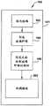
图1A是用来形成玻璃纤维的无粘结剂分层幅材或叠毡的方法的示例性实施例的流程图;1A is a flowchart of an exemplary embodiment of a method for forming a binderless layered web or pack of glass fibers;
图1B是用来形成玻璃纤维的无粘结剂缠结幅材的方法的示例性实施例的流程图;Figure IB is a flow diagram of an exemplary embodiment of a method for forming a binderless entangled web of glass fibers;
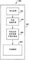
图1C是用来形成玻璃纤维的无粘结剂分层且缠结的幅材或叠毡的方法的示例性实施例的流程图;1C is a flow diagram of an exemplary embodiment of a method for forming a binderless layered and entangled web or pack of glass fibers;
图2A是用来形成具有干粘结剂的玻璃纤维的分层的幅材或叠毡的方法的示例性实施例的流程图;2A is a flowchart of an exemplary embodiment of a method for forming a layered web or pack of glass fibers with a dry binder;
图2B是用来形成具有干粘结剂的玻璃纤维的无粘结剂缠结幅材的方法的示例性实施例的流程图;2B is a flowchart of an exemplary embodiment of a method for forming a binderless entangled web of glass fibers with dry binder;
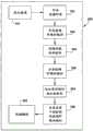
图2C是用来形成具有干粘结剂的玻璃纤维的无粘结剂分层且缠结的幅材或叠毡的方法的示例性实施例的流程图;2C is a flowchart of an exemplary embodiment of a method for forming a binder-free layered and entangled web or pack of glass fibers with dry binder;
图2D是用来形成具有干粘结剂的玻璃纤维的无粘结剂分层且缠结的幅材或叠毡的方法的示例性实施例的流程图;2D is a flowchart of an exemplary embodiment of a method for forming a binder-free layered and entangled web or pack of glass fibers with dry binder;
图3A是用来形成玻璃纤维的无粘结剂的分层的幅材或叠毡的示例性设备的示意图;3A is a schematic diagram of an exemplary apparatus for forming a binderless layered web or pack of glass fibers;
图3B是用来形成玻璃纤维的无粘结剂的缠结的幅材的示例性设备的示意图;3B is a schematic diagram of an exemplary apparatus for forming a binderless entangled web of glass fibers;
图3C是用来形成玻璃纤维的无粘结剂的分层且缠结的幅材或叠毡的示例性设备的示意图;3C is a schematic diagram of an exemplary apparatus for forming a binderless layered and entangled web or pack of glass fibers;
图3D是用来形成玻璃纤维的无粘结剂的分层且缠结的幅材或叠毡的示例性设备的示意图;3D is a schematic diagram of an exemplary apparatus for forming a binderless layered and entangled web or pack of glass fibers;
图3E是示例性积累装置的示意图;3E is a schematic diagram of an exemplary accumulation device;
图3F是示例性转移装置的示意图;3F is a schematic diagram of an exemplary transfer device;
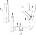
图4是用来形成玻璃纤维的幅材的成形设备的示意图;4 is a schematic diagram of a forming apparatus used to form a web of glass fibers;
图5是用来形成具有干粘结剂的玻璃纤维的幅材或叠毡的示例性设备的示意图;5 is a schematic diagram of an exemplary apparatus for forming a web or pack of fiberglass with dry binder;
图5A是用来形成具有干粘结剂的玻璃纤维的幅材或叠毡的示例性设备的示意图;5A is a schematic diagram of an exemplary apparatus for forming a web or pack of fiberglass with dry binder;
图5B是用来形成具有干粘结剂的玻璃纤维的幅材或叠毡的示例性设备的示意图;5B is a schematic diagram of an exemplary apparatus for forming a web or pack of fiberglass with dry binder;
图6是用来形成纤维材料的叠毡的过程的立视示意图;Figure 6 is a schematic elevational view of a process for forming a pack of fibrous material;
图7是用来从纤维材料形成叠毡的过程的平面示意图;Figure 7 is a schematic plan view of a process for forming a pack from a fibrous material;
图8是用来形成具有干粘结剂的玻璃纤维的幅材或叠毡的示例性设备的示意图;8 is a schematic diagram of an exemplary apparatus for forming a web or pack of fiberglass with dry binder;
图9A是沿图8的9A-9A线截取的剖视图;9A is a cross-sectional view taken along
图9B是沿图8的9A-9A线截取的剖视图;9B is a cross-sectional view taken along
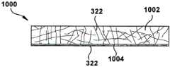
图10A是隔热产品的示例性实施例的示意图;10A is a schematic diagram of an exemplary embodiment of an insulating product;
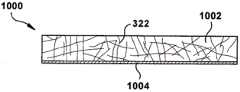
图10B是隔热产品的示例性实施例的示意图;10B is a schematic diagram of an exemplary embodiment of an insulating product;
图10C是隔热产品的示例性实施例的示意图;10C is a schematic diagram of an exemplary embodiment of an insulating product;
图10D是隔热产品的示例性实施例的示意图;10D is a schematic diagram of an exemplary embodiment of an insulating product;
图10E是隔热产品的示例性实施例的示意图;10E is a schematic diagram of an exemplary embodiment of an insulating product;
图10F是隔热产品的示例性实施例的示意图;10F is a schematic diagram of an exemplary embodiment of an insulating product;
图10G是隔热毛层或叠毡的示例性实施例的示意图;10G is a schematic diagram of an exemplary embodiment of an insulating batt or pack;
图10H是隔热毛层或叠毡的示例性实施例的示意图;10H is a schematic diagram of an exemplary embodiment of an insulating batt or pack;
图10I是隔热毛层或叠毡的示例性实施例的示意图;10I is a schematic diagram of an exemplary embodiment of an insulating batt or pack;
图11是用来生产短纤维的装置的示意图;Figure 11 is a schematic diagram of an apparatus for producing short fibers;
图12是烹饪炉灶的立体图;Figure 12 is a perspective view of a cooking range;
图12A是烹饪炉灶的立体图;12A is a perspective view of a cooking range;
图13是图示炉灶中的玻璃纤维隔热的示例性实施例的正面剖视图;13 is a front cross-sectional view illustrating an exemplary embodiment of fiberglass insulation in a cooktop;
图13A是图示炉灶中的玻璃纤维隔热的示例性实施例的正面剖视图;13A is a front cross-sectional view illustrating an exemplary embodiment of fiberglass insulation in a cooktop;
图14是图示炉灶中的玻璃纤维隔热的示例性实施例的侧面剖视图;14 is a side cross-sectional view illustrating an exemplary embodiment of fiberglass insulation in a cooktop;
图14A是图示炉灶中的玻璃纤维隔热的示例性实施例的侧面剖视图;14A is a side cross-sectional view illustrating an exemplary embodiment of fiberglass insulation in a cooktop;
图15A-15C图示用无粘结剂或干粘结剂的玻璃纤维毛层制成压缩模塑的玻璃纤维产品的方法的示例性实施例;15A-15C illustrate an exemplary embodiment of a method of making a compression molded fiberglass product from a binderless or dry binder fiberglass batt;
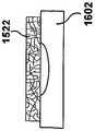
图16A-16C图示用无粘结剂或干粘结剂的玻璃纤维毛层制成真空模塑的玻璃纤维产品的方法的示例性实施例;16A-16C illustrate an exemplary embodiment of a method of making a vacuum molded fiberglass product from a binderless or dry binder fiberglass batt;
具体实施方式Detailed ways
现在将随机参考本发明的具体示例性实施例描述本发明。然而,本发明可以实施为不同形式并且不应当被解释为限于这里阐述的实施例。更确切地说,提供这些实施例使得本公开将彻底且完整,并且将完全传达本发明的范围到本领域技术人员。The invention will now be described with random reference to specific exemplary embodiments of the invention. However, the present invention may be embodied in different forms and should not be construed as limited to the embodiments set forth herein. Rather, these embodiments are provided so that this disclosure will be thorough and complete, and will fully convey the scope of the invention to those skilled in the art.
除非另外定义,这里使用的所有技术和科学术语与本发明所属领域的本领域技术人员通常理解的具有相同的含义。本发明的描述中使用的术语这里仅用来描述特别实施例并且不意图是本发明的限制。如本发明的描述和所附权利要求中使用的,单数形式“一”,“一个”和“该”意图也包括复数形式,除非上下文另外清除地表明。Unless otherwise defined, all technical and scientific terms used herein have the same meaning as commonly understood by one of ordinary skill in the art to which this invention belongs. The terms used in the description of the present invention are used herein to describe particular embodiments only and are not intended to be limiting of the present invention. As used in the description of the invention and the appended claims, the singular forms "a," "an," and "the" are intended to include the plural forms as well, unless the context clearly dictates otherwise.
除非另外指示,如说明书和权利要求中使用的表达诸如长度、宽度、高度等等的尺寸的量的所有数要被理解为在一切情况下由术语“大约”修饰。因此,除非另外指示,说明书和权利要求中阐述的数值性质是可以随本发明的实施例中设法获得的希望性质而改变的近似值。虽然阐述本发明的宽阔范围的数值范围和参数是近似值,但具体例子中阐述的数值被尽可能精确地叙述。然而,任何数值固有地包含必然地由它们相应测量中出现的误差产生的一定误差。Unless otherwise indicated, all numbers expressing quantities such as length, width, height, etc., as used in the specification and claims, are to be understood as modified in all instances by the term "about". Accordingly, unless otherwise indicated, the numerical properties set forth in the specification and claims are approximations that can vary depending upon the desired properties sought to be obtained in embodiments of the present invention. Notwithstanding that the numerical ranges and parameters setting forth the broad scope of the invention are approximations, the numerical values set forth in the specific examples are reported as precisely as possible. Any numerical value, however, inherently contain certain errors necessarily resulting from errors in their respective measurements.
具体实施方式和附图公开一种从纤维材料形成叠毡的改进的方法。通常,改进的连续方法将施加湿粘结剂到纤维化材料的传统方法替换为在没有任何粘结剂(即,将纤维粘结在一起的材料)的情况下制造纤维的毛层或叠毡的新的方法和/或通过干粘结剂制造纤维的毛层或叠毡的新的方法。DETAILED DESCRIPTION OF THE PREFERRED EMBODIMENTS An improved method of forming a pack from a fibrous material is disclosed. Often, the improved continuous process replaces the traditional method of applying a wet binder to the fiberized material by making a batt or pack of fibers without any binder (ie, the material that binds the fibers together) and/or a new method of making batts or packs of fibers by dry binders.
如这里使用的,术语“纤维材料”被定义用来意指通过拉伸或变细熔融材料形成的任何材料。如这里使用的,术语“叠毡”被定义用来意指由通过粘合剂且/或通过机械缠结连接在一起的纤维材料形成的任何产品。As used herein, the term "fibrous material" is defined to mean any material formed by drawing or attenuating molten material. As used herein, the term "pack" is defined to mean any product formed from fibrous materials joined together by a binder and/or by mechanical entanglement.
图1A和3A示出从纤维材料形成叠毡300(见图3A)的连续过程或方法100的第一示例性实施例。方法100的步骤周围的虚线101表示该方法是连续的方法,如下面将更详细地描述的。将根据玻璃纤维描述该方法和叠毡,但该方法和叠毡也可以应用于由其它矿物材料(诸如,岩石、矿渣和玄武岩的非限制性例子)形成的纤维产品的制造。FIGS. 1A and 3A illustrate a first exemplary embodiment of a continuous process or
参考图1A,在步骤102,熔化玻璃。例如,图3A示意性地示出熔炉314。熔炉314可以供应熔融玻璃312到前炉316。熔炉和前炉在该技术领域中是已知的并且在这里将不被描述。熔融玻璃312可以由各种原材料形成,该各种原材料以一定比例组合以便给出希望的化学组成。Referring to Figure 1A, at
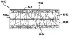
回头参考图1A,熔融玻璃312被处理以形成104玻璃纤维322。熔融玻璃312可以以多种不同方式被处理以形成纤维322。例如,在图3A示出的例子中,熔融玻璃312从前炉316流到一个或更多个旋转成纤器318。旋转成纤器18接收熔融玻璃312并且随后形成玻璃纤维322的薄片320。如下面将更详细地讨论的,由旋转成纤器318形成的玻璃纤维322是长的且细的。因此,可以使用足以形成长的且细的玻璃纤维322的任何希望的成纤器(旋转的或其它形式的)。虽然图3A中示出的实施例示出一个旋转成纤器318,但应当理解,可以使用任何希望数量的旋转成纤器318。在另一示例性实施例中,纤维322由火焰细化形成。Referring back to FIG. 1A ,
长的且细的纤维可以呈现很多种不同形式。在示例性实施例中,长的且细的纤维具有从大约6.35毫米(0.25英寸)到大约254毫米(10.0英寸)的范围中的长度和从大约9HT到大约35HT的范围中的直径尺寸。HT代表0.254微米(十万分之一英寸)。在示例性实施例中,纤维322具有从大约25.4毫米(1.0英寸)到大约127毫米(5.0英寸)的范围中的长度和从大约14HT到大约25HT的范围中的直径尺寸。在示例性实施例中,纤维322具有大约76.2毫米(3英寸)的长度和大约16-17HT的平均直径。虽然不受理论约束,但相信,相对长的且细的纤维的使用有利地提供一种叠毡,与具有较短且较粗的纤维的类似尺寸的叠毡相比,该叠毡具有更好的隔热性能和隔音性能,以及更好的强度性质,诸如较高的抗张强度和/或较高的粘结强度。Long and thin fibers can take many different forms. In an exemplary embodiment, the long and thin fibers have lengths ranging from about 6.35 millimeters (0.25 inches) to about 254 millimeters (10.0 inches) and diameter dimensions ranging from about 9HT to about 35HT. HT stands for 0.254 microns (one hundred thousandth of an inch). In an exemplary embodiment,
在纤维是玻璃纤维的示例性实施例中,术语无粘结剂表示纤维材料、幅材和/或叠毡仅包括99%或100%的玻璃,或包括99%或100%的玻璃加惰性内容物。内容物是不将玻璃纤维粘结在一起的任何材料。例如,在这里描述的示例性无粘结剂实施例中,在玻璃纤维形成之后,玻璃纤维322可以可选地被涂覆或部分地涂覆有润滑剂。例如,玻璃纤维322可以涂覆有不将玻璃纤维粘结在一起的任何润滑材料。在示例性实施例中,该润滑剂可以是硅树脂化合物,诸如硅氧烷、二甲基硅氧烷和/或硅烷。该润滑剂也可以是其它材料或材料的组合,诸如,油或油乳化液。该油或油乳化液可以是矿物油或矿物油乳化液和/或植物油或植物油乳化液。In exemplary embodiments where the fibers are glass fibers, the term binderless means that the fiber material, web and/or pack includes only 99% or 100% glass, or 99% or 100% glass plus inert content thing. The content is any material that does not bind the fiberglass together. For example, in the exemplary binderless embodiments described herein, the
玻璃纤维可以以很多种不同方式被涂覆或部分地涂覆有润滑剂。例如,润滑剂可以被喷到玻璃纤维322上。在示例性实施例中,润滑剂被构造用来在玻璃纤维322移动通过制造过程并且接触各种设备以及其它玻璃纤维时防止损坏玻璃纤维322。润滑剂也可以用于减少制造过程中的粉尘。可选的润滑剂的施加可以由任何希望结构、机构或装置精确地控制。Glass fibers can be coated or partially coated with lubricants in many different ways. For example, a lubricant can be sprayed onto the
参考图1A,形成106纤维的幅材321,该纤维的幅材没有将纤维粘结在一起的粘结剂或其它材料。幅材321可以以很多种不同方式形成。在图3A示出的例子中,玻璃纤维322由可选的收集构件324收集。收集构件324被成形且设计尺寸以接收玻璃纤维322。收集构件324被构造用来使玻璃纤维322转向导管330以便转移到下游处理站,例如形成幅材321的成形设备332。在其它实施例中,玻璃纤维322可以被收集在传送机构(未示出)上以形成幅材。Referring to Figure 1A, a
成形设备332可以被构造用来形成具有希望厚度的纤维材料的连续的干幅材321。在一个示例性实施例中,本申请中公开的干幅材321可以具有大约6.35毫米(0.25英寸)到大约101.6毫米(4英寸)厚的范围中的厚度和大约3.2千克/立方米(0.2磅/立方英尺)到大约9.6千克/立方米(0.6磅/立方英尺)的范围中的密度。在一个示例性实施例中,本申请中公开的干幅材321可以具有大约25.4毫米(1英寸)到大约76.2毫米(3英寸)厚的范围中的厚度和大约4.8千克/立方米(0.3磅/立方英尺)到大约8千克/立方米(0.5磅/立方英尺)的范围中的密度。在一个示例性实施例中,本申请中公开的干幅材321可以具有大约38.1毫米(1.5英寸)的厚度和大约6.4千克/立方米(0.4磅/立方英尺)的密度。成形设备332可以呈现很多种不同形式。可以使用用来形成玻璃纤维的干幅材321的任何布置。The forming
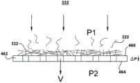
在一个示例性实施例中,成形设备332包括旋转滚筒,该旋转滚筒具有较高或较低压力的成形表面和区域。参考图4,收集纤维322的成形表面462的侧面460上的压力P1高于相对的侧面464上的压力P2。这个压力降ΔΡ引起纤维322聚集在成形表面462上以形成干幅材321。在一个示例性实施例中,跨越成形表面462的压力降ΔΡ被控制为低的压力并且产生低面积重量幅材。例如,压力降ΔΡ可以是从大约12.7毫米(0.5英寸)水柱到762毫米(30英寸)水柱。导致这个低的压力降ΔΡ的穿过正被成形的幅材的空气的速度V可以达到304.8米(1000英尺)每分钟。In an exemplary embodiment, the forming
低面积重量幅材321具有大约53.82克每平方米(5克每平方英尺)到大约538.2克每平方米(50克每平方英尺)的面积重量。低面积重量幅材可以具有上述密度和厚度范围。低面积重量幅材可以具有大约6.35毫米(0.25英寸)到大约101.6毫米(4英寸)厚、大约25.4毫米(1英寸)到大约76.2毫米(3英寸)厚或大约38.1毫米(1.5英寸)的范围中的厚度。低面积重量幅材可以具有大约大约3.2千克/立方米(0.2磅/立方英尺)到大约9.6千克/立方米(0.6磅/立方英尺),大约4.8千克/立方米(0.3磅/立方英尺)到大约8千克/立方米(0.5磅/立方英尺)或大约6.4千克/立方米(0.4磅/立方英尺)的范围中的密度。参考图3A,干幅材321离开成形设备332。在一个示例性实施例中,低面积重量幅材321具有测量的面积重量分布变化系数=Σ(一个标准差)/平均(平均值)×100%=0和40%之间。在示例性实施例中,重量分布变化系数小于30%、小于20%或小于10%。在一个示例性实施例中,重量分布变化系数在25%和30%之间,诸如大约28%。在一个示例性实施例中,重量分布变化系数是大约28%。重量分布变化系数通过用光台测量大的样品(例如1.8米(6英尺)×3米(10英尺)样品)的多个小的样品区域尺寸(例如,2”×2”)来测得。The low
在图1A示出的例子中,幅材321或多个幅材被分层108。例如,单个幅材321可以沿机器方向搭叠或与机器方向成90度横向搭叠以形成分层的幅材350。在另一实施例中,该幅材可以被切割成数个部分,并且该部分彼此堆叠以形成分层的幅材。在又一示例性实施例中,一个或更多个二重成纤器318和成形设备332可以被实现使得两个或更多个幅材被平行地连续生产。平行的幅材然后被堆叠在彼此顶部上以形成分层的幅材。In the example shown in FIG. 1A ,
在一个示例性实施例中,分层机构332是与传送器336关联地起作用的搭叠机构或横向搭叠机构。传送器336被构造用来沿如箭头D1指示的机器方向移动。搭叠或横向搭叠机构被构造用来接收连续的幅材321并且在第一传送器沿机器方向D1移动时将连续的幅材的交替的层存放在第一传送器336上。在存放过程中,搭叠机构334将沿如箭头D1指示的机器方向形成交替的层或者横向搭叠机构334将沿横穿机器方向形成交替的层。另外的幅材321可以成形并且由另外的搭叠或横向搭叠机构搭叠或横向搭叠以增加层的数量和生产量。In one exemplary embodiment, the
在一个示例性实施例中,横向搭叠机构被构造用来精确地控制连续的幅材321的移动并且将连续的幅材存放在传送器336上使得连续的幅材不被损坏。横向搭叠机构可以包括任何希望结构并且可以被构造用来以任何希望方式进行操作。在一个示例性实施例中,横向搭叠机构包括头部(未示出),该头部被构造用来与机器方向D1成90度来回移动。在这个实施例中,协调移动头部的速度使得沿两个横穿机器方向的头部的移动基本上相同,因此提供作为结果的纤维体的层的一致性。在示例性实施例中,横向搭叠机构包括竖直传送器(未示出),该竖直传送器被构造用来以传送器336的中心线为中心。竖直传送器还被构造成从传送器336上方的枢轴机构悬挂以便将连续幅材存放在传送器336上。虽然上面已经描述横向搭叠机构的多个例子,但应当理解,横向搭叠机构可以是其它结构、机构或装置或其组合。In one exemplary embodiment, the transverse lapping mechanism is configured to precisely control the movement of the
分层的幅材350可以具有任何希望厚度。分层的幅材的厚度根据多个变量而定。首先,分层的幅材350的厚度根据由成形设备332形成的连续的幅材321的厚度而定。第二,分层的幅材350的厚度根据分层机构334将连续的幅材321的层存放在传送器336上的速度而定。第三,分层的幅材334的厚度根据传送器336的速度而定。在示出的实施例中,分层的幅材350具有从大约2.54毫米(0.1英寸)到大约508毫米(20.0英寸)的范围中的厚度。在示例性实施例中,横向搭叠机构334可以形成具有从1层到60层的分层的幅材350。可选地,横向搭叠机构可以是可调节的,因此允许横向搭叠机构334形成具有任何希望宽度的叠毡。在某些实施例中,该叠毡可以具有从大约2489.2毫米(98.0英寸)到大约5994.4毫米(236.0英寸)的范围中的总宽度。The
在一个示例性实施例中,在由图1A中的虚线框101表示的连续的过程中生产分层的幅材350。由成纤器318生产的纤维被直接送到成形设备332(即,该纤维不被收集且包装且随后拆开以便用于远处的成形设备)。幅材321被直接提供到分层装置352(即,该幅材不被成形并且卷起且随后展开以便用于远处的分层装置352)。在该连续的过程的示例性实施例中,该过程(图1A中的成形和分层)的每一个连接到纤维化过程,使得来自成纤器的纤维被其它过程使用而不为了以后使用而被存储。在该连续过程的另一示例性实施例中,一个或多个成纤器318的生产量可多于成形设备332和分层装置352的需求。因此,为了使过程连续,成纤器318不需要连续向成形设备332供应纤维。例如,成纤器318可生产在同一工厂中在该连续过程中积累并被提供到成形设备332的多批纤维,但在该连续过程中纤维不被压缩、运输和重新打开。作为连续过程的另一例子,成纤器318生产的纤维可交替地被转向成形设备332并转向另一成形设备或用于一些其他用途或产品。在连续过程的另一例子中,成纤器318生产的纤维的一部分持续被引导到成形设备332,并且纤维的剩余部分被引导到另一成形设备或用于一些其他用途或产品。In one exemplary embodiment,
图3E图示纤维322可被图3A-3D所示的任何例子中的积累器390收集。箭头392表示积累器390以受控方式将纤维322提供到成形设备332。在被提供到成形设备332之前,纤维322可在积累器390中停留预定时间段,以容许纤维冷却。在一个示例性实施例中,积累器390以与纤维322被提供到积累器390相同的速率将纤维322提供到成形设备332。因此,在本示例性实施例中,纤维在积累器中停留和冷却的时间由积累器中纤维322的量决定。在本例子中,停留时间等于积累器中的纤维量除以积累器将纤维提供到成形设备332的速率。在另一示例性实施例中,积累器390可选择性地开始和停止分配纤维和/或调整分配纤维的速率。Figure 3E illustrates that
图3F图示纤维322可通过图3A-3D所示的任何例子中的转向机构398在成形设备332和第二成形站332’之间选择性地转向。在一个示例性实施例中,图3A-3D所示的实施例可具有积累器390和转向机构398两者。Figure 3F illustrates that the
在一个示例性实施例中,幅材321相对厚并且具有低面积重量,然而该连续的过程具有高的生产量,并且成纤器生产的所有纤维都用于制造幅材。例如,幅材321的单层可以具有大约53.82克每平方米(5克每平方英尺)到大约538.2克每平方米(50克每平方英尺)的面积重量。低面积重量幅材可以具有上述密度和厚度范围。高输出连续过程可以产生大约340千克/小时(750磅/小时)和680千克/小时(1500磅/小时)之间,诸如至少408千克/小时(900磅/小时)或至少567千克/小时(1250磅/小时)。分层的幅材350可以用于很多种不同应用。In an exemplary embodiment, the
图1B和3B示出在不使用粘结剂的情况下从纤维材料形成叠毡300(见图3B)的方法150的第二示例性实施例。方法150的步骤周围的虚线151表示该方法是连续的方法。参考图1B,熔化玻璃102。可以如上面参考图3A描述的那样熔化玻璃。熔融玻璃312被处理而形成104玻璃纤维322。可以如上面参考图3A描述的那样处理熔融玻璃312以形成纤维322。形成106纤维的幅材321,该纤维的幅材没有将纤维粘结在一起的粘结剂或其它材料。可以如上面参考图3A描述的那样形成幅材321。FIGS. 1B and 3B illustrate a second exemplary embodiment of a
参考图1B,幅材321的纤维322机械地缠结202以形成缠结的幅材352(见图3B)。参考图3B,幅材321的纤维可以通过缠结机构345(诸如针刺装置)机械地缠结。缠结机构345被构造用来缠结幅材321的单个纤维322。缠结玻璃纤维322将幅材的纤维束缚在一起。缠结引起幅材的机械性质(例如,抗张强度和剪切强度)被改善。在示出的实施例中,缠结机构345是针刺机构。在其它实施例中,缠结机构345可以包括其它结构、机构或装置或其组合(包括缝合机构的非限制性例子)。Referring to Figure IB,
缠结的幅材352可以具有任何希望厚度。缠结的幅材的厚度根据由成形设备332形成的连续幅材321的厚度和由缠结机构345引起的连续幅材321的压缩量而定。在示例性实施例中,缠结的幅材352具有从大约2.54毫米(0.1英寸)到大约50.8毫米(2.0英寸)的范围中的厚度。在示例性实施例中,缠结的幅材352具有从大约12.7毫米(0.5英寸)到大约44.45毫米(1.75英寸)的范围中的厚度。例如,在一个示例性实施例中,缠结的幅材的厚度是大约1/2"。The
在一个示例性实施例中,缠结的幅材352在连续的过程151中被生产。由成纤器318生产的纤维被直接送到成形设备332(即,该纤维不被收集且包装且随后拆开以便用于远处的成形设备)。幅材321被直接提供到缠结装置345(即,该幅材不被成形并且卷起且随后展开以便用于远处的缠结装置345)。缠结的幅材352可以用于很多种不同应用。在该连续的过程的示例性实施例中,该过程(图1B中的成形和缠结)的每一个连接到纤维化过程,使得来自成纤器的纤维被其它过程使用而不为了以后使用而被存储。在该连续过程的另一示例性实施例中,一个或多个成纤器318的生产量可多于成形设备332和/或缠结装置345的需求。因此,为了使过程连续,成纤器318不需要连续向成形设备332供应纤维。例如,成纤器318可生产在同一工厂中在该连续过程中积累并被提供到成形设备332的多批纤维,但在该连续过程中纤维不被压缩、运输和重新打开。作为连续过程的另一例子,成纤器318生产的纤维可交替地被转向成形设备332并转向另一成形设备或用于一些其他用途或产品。在连续过程的另一例子中,成纤器318生产的纤维的一部分持续被引导到成形设备332,并且纤维的剩余部分被引导到另一成形设备或用于一些其他用途或产品。In an exemplary embodiment,
图3D图示与用于形成单层高密度叠毡300的图3B所示的实施例类似的设备的示例性实施例。例如,图3D所示的实施例可生产比图3B所示的实施例生产的密度最大的叠毡密度更大的叠毡300。除了在成形站332和缠结机构345之间设置压缩机构375和/或缠结机构345包括压缩机构之外,图3D的设备与图3B的实施例相对应。压缩机构375在幅材被提供到缠结机构345之前如箭头377所示地压缩幅材321和/或幅材321在压缩机构的入口处被压缩。所形成的缠结幅材352具有高密度。压缩机构可呈现各种不同的形式。压缩机构345的例子包括但不限于辊、带、旋转钉枪、额外的针刺机构、穿孔带(与缠结幅材352相反的带侧面被施加以负压,见图4所示的类似例子)、包括所列压缩机构的任何特征的任何组合的任何机构等。可使用用于压缩幅材的任何布置。当缠结机构345包括压缩机构时,在图3D所示的单层高密度叠毡300实施例中可省略压缩机构375。压缩机构375和/或缠结机构345执行的压缩可以是压缩和/或针刺的任何组合,其除缠结纤维之外还压缩叠毡。用于生产高密度叠毡的压缩和针刺顺序的例子包括但不限于用辊压缩然后针刺,针刺两次,用辊压缩然后针刺两次,针刺三次,预针刺-从顶部针刺-从底部针刺,预针刺-从底部针刺-从顶部针刺,用辊压缩-从顶部针刺-从底部针刺,以及用辊压缩-从底部针刺-从顶部针刺。FIG. 3D illustrates an exemplary embodiment of an apparatus similar to that shown in FIG. 3B for forming a single layer
图3D的高密度缠结幅材352可具有任何希望的厚度。缠结幅材的厚度是成形设备332形成的连续幅材321的厚度及压缩机构375和缠结机构345压缩的连续幅材321的压缩量的函数。在示例性实施例中,图3D的高密度缠结幅材352具有在大约2.54毫米(0.1英寸)到大约127毫米(5英寸)范围内的厚度。在示例性实施例中,高密度缠结幅材352具有在大约6.35毫米(0.250英寸)到大约76.2毫米(3.0英寸)范围内的厚度。在示例性实施例中,高密度缠结幅材具有在6.4千克/立方米(0.4磅/立方英尺)至大约192千克/立方米(12磅/立方英尺)范围内的密度。在一个示例性实施例中,在连续过程中以与参照图3B描述的类似方式生产图3D的高密度缠结幅材352。The high density
图1C和3C示出在不使用粘结剂的情况下从纤维材料形成叠毡370(见图3C)的方法170的另一示例性实施例。参考图1C,熔化玻璃102。方法171的步骤周围的虚线170表示该方法是连续的方法。可以如上面参考图3A描述的那样熔化玻璃。回头参考图1C,熔融玻璃312被处理以形成104玻璃纤维322。可以如上面参考图3A描述的那样处理熔融玻璃312以形成纤维322。参考图1C,形成106纤维的幅材321,该纤维的幅材没有将纤维粘结在一起的粘结剂或其它材料。可以如上面参考图3A描述的那样形成幅材321。参考图1C,幅材321或多个幅材被分层108。幅材321或多个幅材可以如上面参考图3A描述的那样被分层。参考图1C,分层的幅材350的纤维322被机械地缠结302以形成分层的幅材的缠结的叠毡370。Figures 1C and 3C illustrate another exemplary embodiment of a
参考图3C,分层的幅材350的纤维可以通过缠结机构345(诸如针刺装置)被机械地缠结。缠结机构345被构造用来缠结形成分层的幅材的层的单个纤维322。缠结玻璃纤维322将分层的幅材350的纤维束缚在一起以形成叠毡。机械缠结引起幅材的机械性质(例如,抗张强度和剪切强度)被改善。在示出的实施例中,缠结机构345是针刺机构。在其它实施例中,缠结机构345可以包括其它结构、机构或装置或其组合(包括缝合机构的非限制性例子)。Referring to Figure 3C, the fibers of the
分层的幅材350的缠结的叠毡370可以具有任何希望厚度。缠结的叠毡的厚度根据多个变量而定。首先,缠结的叠毡的厚度根据由成形设备332形成的连续的幅材321的厚度而定。第二,缠结的叠毡370的厚度根据搭叠或横向搭叠机构334将连续的幅材321的层存放在传送器336上的速度而定。第三,缠结的叠毡370的厚度根据传送器336的速度而定。第四,缠结的叠毡370的厚度根据由缠结机构345引起的分层的幅材350的压缩量而定。缠结的叠毡370可以具有从大约2.54毫米(0.1英寸)到大约508毫米(20.0英寸)的范围中的厚度。在示例性实施例中,缠结的叠毡370可以具有从1层到60层。每一个缠结的幅材层352可以为从2.54到50.8毫米(从0.1到2英寸)厚。例如,每一个缠结的幅材层可以为大约12.7毫米(0.5英寸)厚。The entangled pack 370 of layered
在一个示例性实施例中,缠结的叠毡370在连续的过程中被生产。由成纤器318生产的纤维被直接送到成形设备332(即,该纤维不被收集且包装且随后拆开以便用于远处的成形设备)。幅材321被直接提供到分层装置352(即,该幅材不被成形并且卷起且随后展开以便用于远处的分层装置352)。分层的幅材350被直接提供到缠结装置345(即,分层的幅材不被成形并且卷起且随后展开以便用于远处的缠结装置345)。在该连续的过程的示例性实施例中,该过程(图1C中的成形、分层和缠结)的每一个连接到纤维化过程,使得来自成纤器的纤维被其它过程使用而不被存储以便以后使用。在该连续过程的另一示例性实施例中,一个或多个成纤器318的生产量可多于成形设备332、分层装置352和/或缠结装置的需求。因此,为了使过程连续,成纤器318不需要连续向成形设备332供应纤维。例如,成纤器318可生产在同一工厂中在该连续过程中积累并被提供到成形设备332的多批纤维,但在该连续过程中纤维不被压缩、运输和重新打开。作为连续过程的另一例子,成纤器318生产的纤维可交替地被转向成形设备332并转向另一成形设备或用于一些其他用途或产品。在连续过程的另一例子中,成纤器318生产的纤维的一部分持续被引导到成形设备332,并且纤维的剩余部分被引导到另一成形设备或用于一些其他用途或产品。In one exemplary embodiment, the entangled pack 370 is produced in a continuous process. The fibers produced by
在一个示例性实施例中,分层的幅材的缠结的叠毡370由相对厚的并且具有低面积重量的幅材321或多个幅材制成,然而该连续的过程具有高的生产量,并且成纤器生产的全部纤维都用于制造缠结的叠毡。例如,幅材321的单个层可以具有上面提及的面积重量,厚度和密度。高输出连续过程可以产生大约340千克/小时(750磅/小时)和680千克/小时(1500磅/小时)之间,诸如至少408千克/小时(900磅/小时)或至少567千克/小时(1250磅/小时)。在示例性实施例中,通过幅材321的分层(诸如幅材的搭叠或横向搭叠),促进连续的过程的高的幅材生产量和机械缠结(诸如针刺)的组合。通过分层该幅材321,穿过分层装置的材料的直线速度慢于成形幅材的速度。例如,在连续的过程中,两层幅材将以成形幅材的速度的1/2穿过缠结设备345(三层则1/3该速度,等等)。这种速度减小允许连续的过程,其中高生产量、低面积重量幅材321被成形并且转化为多层机械缠结的叠毡370。分层的幅材的缠结的叠毡370可以用于很多种不同应用。In one exemplary embodiment, the entangled pack 370 of layered webs is made from a relatively thick and low
在示例性实施例中,长的细的纤维的分层和缠结导致高强度的幅材370。例如,本申请中描述的长的细的玻璃纤维的缠结导致具有高的抗张强度和高的粘结强度的分层的缠结的幅材。抗张强度是当沿幅材的长度或宽度的方向拉幅材时幅材370的强度。粘结强度是当沿幅材的厚度的方向拉开幅材370时该幅材的强度。In the exemplary embodiment, the delamination and entanglement of the long thin fibers results in a high strength web 370 . For example, the entanglement of the long thin glass fibers described in this application results in a layered entangled web with high tensile strength and high bond strength. Tensile strength is the strength of the web 370 when the web is tented in the direction of the length or width of the web. Bond strength is the strength of the web 370 when the web is pulled apart in the direction of the thickness of the web.
抗张强度和粘结强度可以以很多种不同方式被测试。在一个示例性实施例中,机器(诸如Instron机器)以固定的速度(在下面描述的例子中,304.8毫米每秒(12英寸每秒))将幅材370拉开并且测量拉开该幅材所需的力的量。记录拉开该幅材所需的力(包括在幅材裂开或失效之前施加到幅材的峰值力)。Tensile strength and bond strength can be tested in many different ways. In one exemplary embodiment, a machine (such as an Instron machine) pulls the web 370 apart at a fixed speed (in the example described below, 304.8 millimeters per second (12 inches per second)) and measures the pull apart amount of force required. The force required to pull the web apart (including the peak force applied to the web before it splits or fails) is recorded.
在测试抗张强度的一种方法中,通过以下手段测量沿长度方向的抗张强度:沿幅材的宽度夹紧幅材的端部;在固定的速度(在下面提供的例子中,304.8毫米每秒(12英寸每秒))通过机器沿幅材的长度拉幅材370;和记录沿幅材的长度的方向施加的峰值力。沿宽度方向的抗张强度通过以下手段被测量:沿幅材的宽度夹紧幅材的侧部;在固定的速度(在下面提供的例子中,304.8毫米每秒(12英寸每秒))沿幅材的宽度拉幅材370;和记录施加的峰值力。沿长度方向的抗张强度和沿宽度方向的抗张强度被平均以确定该样品的抗张强度。In one method of testing tensile strength, tensile strength is measured lengthwise by clamping the ends of the web along the width of the web; at a fixed speed (in the example provided below, 304.8 mm The web 370 was tentered by the machine along the length of the web per second (12 inches per second); and the peak force applied in the direction of the length of the web was recorded. The tensile strength in the width direction is measured by clamping the sides of the web along the width of the web; width of the web tenter web 370; and record the peak force applied. The tensile strength in the length direction and the tensile strength in the width direction are averaged to determine the tensile strength of the sample.
在测试粘结强度的一种方法中,提供预定尺寸(在下面描述的例子中,6”×6”)的样品。样品的每一侧例如通过胶合粘结到基板。以固定的速度(在下面提供的例子中,304.8毫米每秒(12英寸每秒))通过机器拉开样品的相对侧上的基板,并且记录施加的峰值力。施加的峰值力除以样品的面积(在下面描述的例子中,6”×6”)以提供以力除以面积的形式的粘结强度。In one method of testing bond strength, a sample of a predetermined size (in the example described below, 6" x 6") is provided. Each side of the sample is bonded to the substrate, eg by gluing. The substrate on the opposite side of the sample was pulled apart by the machine at a fixed speed (in the example provided below, 304.8 millimeters per second (12 inches per second)) and the peak force applied was recorded. The peak force applied was divided by the area of the sample (in the example described below, 6" x 6") to provide the bond strength as force divided by area.
下面的例子被提供用来说明分层的、缠结的幅材370的增加的强度。在这些例子中,不包括粘结剂。即,不包括含水的或干的粘结剂。这些例子不限制本发明的范围,除非在权利要求中被明确列举。提供具有4、6和8层的分层的缠结的幅材的例子。然而,分层的缠结的幅材370可以设置有任何数量的层。分层的缠结的幅材370样品长度、宽度、厚度、搭叠数量和重量可以根据幅材370的应用而变化。在图3D所示的致密的单层实施例中,对于相同的所列厚度,单层高密度叠毡300的每单位面积重量可比以下六段中的例子高,诸如高两倍或更多倍。The following example is provided to illustrate the increased strength of the layered, entangled web 370 . In these examples, no binder is included. That is, no aqueous or dry binder is included. These examples do not limit the scope of the invention unless explicitly recited in the claims. Examples of layered entangled webs with 4, 6 and 8 layers are provided. However, the layered entangled web 370 may be provided with any number of layers. The layered entangled web 370 sample length, width, thickness, number of laps, and weight can vary depending on the application of the web 370. In the dense single layer embodiment shown in Figure 3D, the weight per unit area of the single layer
在一个示例性实施例中,152.4毫米(6英寸)×304.8毫米(12英寸)的,具有多个层(诸如两个搭叠,即,四层)的,12.7毫米(0.5英寸)厚和50.8毫米(2.0英寸)厚之间的幅材370样品具有0.1和0.1.47克/平方厘米(3磅/平方英尺)之间的每单位面积重量,具有大于1.36千克力(3磅力)的抗张强度,并且具有大于18千克力/千克质量(40磅力/磅质量),诸如从大约18千克力/千克质量(40磅力/磅质量)到大约54千克力/千克质量(120磅力/磅质量)的抗张强度对重量比率。在示例性实施例中,这个样品的粘结强度大于0.049克/平方厘米(0.1磅/平方英尺)。在示例性实施例中,这个段落中描述的样品的抗张强度大于2.27千克力(5磅力)。在示例性实施例中,这个段落中描述的样品的抗张强度大于3.4千克力(7.5磅力)。在示例性实施例中,这个段落中描述的样品的抗张强度大于4.5千克力(10磅力)。在示例性实施例中,这个段落中描述的样品的抗张强度大于5.67千克力(12.5磅力)。在示例性实施例中,这个段落中描述的样品的抗张强度大于6.237千克力(13.75磅力)。在示例性实施例中,这个段落中描述的样品的抗张强度在1.36和6.8千克力(3和15磅力)之间。在示例性实施例中,这个段落中描述的样品的粘结强度大于0.98克/平方厘米(2磅/平方英尺)。在示例性实施例中,这个段落中描述的样品的粘结强度大于2.45克/平方厘米(2磅/平方英尺)。在示例性实施例中,这个段落中描述的样品的粘结强度大于4.9克/平方厘米(10磅/平方英尺)。在示例性实施例中,这个段落中描述的样品的粘结强度大于7.35克/平方厘米(15磅/平方英尺)。在示例性实施例中,这个段落中描述的样品的粘结强度大于9.8克/平方厘米(20磅/平方英尺)。在示例性实施例中,这个段落中描述的样品的抗张强度大于2.27千克力(5磅力)并且粘结强度大于0.98克/平方厘米(2磅/平方英尺)。在示例性实施例中,这个段落中描述的样品的抗张强度大于3.4千克力(7.5磅力)并且粘结强度大于7.2.45克/平方厘米(2磅/平方英尺)。在示例性实施例中,这个段落中描述的样品的抗张强度大于4.5千克力(10磅力)并且粘结强度大于4.9克/平方厘米(10磅/平方英尺)。在示例性实施例中,这个段落中描述的样品的抗张强度大于5.67千克力(12.5磅力)并且粘结强度大于7.35克/平方厘米(15磅/平方英尺)。在示例性实施例中,这个段落中描述的样品的抗张强度大于6.237千克力(13.75磅力)并且粘结强度大于9.8克/平方厘米(20磅/平方英尺)。在示例性实施例中,这个段落中描述的样品的抗张强度在1.36和6.8千克力(3和15磅力)之间并且粘结强度在0.147和14.7克/平方厘米(0.3和30磅/平方英尺)之间。In one exemplary embodiment, 152.4 mm (6 inches) by 304.8 mm (12 inches), with multiple layers (such as two overlaps, ie, four layers), 12.7 mm (0.5 inches) thick and 50.8 Samples of Web 370 between millimeters (2.0 inches) thick have a weight per unit area between 0.1 and 0.1.47 grams per square centimeter (3 pounds per square foot) and have a resistance of greater than 1.36 kilogram force (3 pound force) Tensile strength, and has greater than 18 kgf/kg mass (40 lbf/lb mass), such as from about 18 kgf/kg mass (40 lbf/lb mass) to about 54 kgf/kg mass (120 lbf mass) per pound of mass) tensile strength to weight ratio. In an exemplary embodiment, the bond strength of this sample is greater than 0.049 grams per square centimeter (0.1 pounds per square foot). In an exemplary embodiment, the tensile strength of the samples described in this paragraph is greater than 2.27 kilogram force (5 lb force). In an exemplary embodiment, the tensile strength of the samples described in this paragraph is greater than 3.4 kilogram force (7.5 pound force). In an exemplary embodiment, the tensile strength of the samples described in this paragraph is greater than 4.5 kilogram force (10 pound force). In an exemplary embodiment, the tensile strength of the samples described in this paragraph is greater than 5.67 kilogram force (12.5 pound force). In an exemplary embodiment, the tensile strength of the samples described in this paragraph is greater than 6.237 kilogram force (13.75 pound force). In an exemplary embodiment, the tensile strength of the samples described in this paragraph is between 1.36 and 6.8 kilogram force (3 and 15 lbf). In an exemplary embodiment, the bond strength of the samples described in this paragraph is greater than 0.98 grams per square centimeter (2 pounds per square foot). In an exemplary embodiment, the bond strength of the samples described in this paragraph is greater than 2.45 grams per square centimeter (2 pounds per square foot). In exemplary embodiments, the bond strength of the samples described in this paragraph is greater than 4.9 grams per square centimeter (10 pounds per square foot). In an exemplary embodiment, the bond strength of the samples described in this paragraph is greater than 7.35 grams per square centimeter (15 pounds per square foot). In an exemplary embodiment, the bond strength of the samples described in this paragraph is greater than 9.8 grams per square centimeter (20 pounds per square foot). In an exemplary embodiment, the tensile strength of the samples described in this paragraph is greater than 2.27 kilogram force (5 lbf) and the bond strength is greater than 0.98 grams per square centimeter (2 pounds per square foot). In an exemplary embodiment, the tensile strength of the samples described in this paragraph is greater than 3.4 kilogram force (7.5 pound force) and the bond strength is greater than 7.2.45 grams/square centimeter (2 pounds/square foot). In an exemplary embodiment, the tensile strength of the samples described in this paragraph is greater than 4.5 kilogram force (10 lbf) and the bond strength is greater than 4.9 grams per square centimeter (10 pounds per square foot). In an exemplary embodiment, the tensile strength of the samples described in this paragraph is greater than 5.67 kilogram force (12.5 pound force) and the bond strength is greater than 7.35 grams per square centimeter (15 pounds per square foot). In an exemplary embodiment, the tensile strength of the samples described in this paragraph is greater than 6.237 kilogram force (13.75 lbf) and the bond strength is greater than 9.8 grams per square centimeter (20 pounds per square foot). In exemplary embodiments, the tensile strengths of the samples described in this paragraph are between 1.36 and 6.8 kgf (3 and 15 lbf) and the bond strengths are between 0.147 and 14.7 g/cm2 (0.3 and 30 lbf) square feet).
在一个示例性实施例中,152.4毫米(6英寸)×304.8毫米(12英寸)的幅材370样品具有多个层(诸如两个搭叠,即,四层),厚度在12.7毫米(0.5英寸)和44.45毫米(1.75英寸)之间,具有0.059和0.13克/平方厘米(0.12和0.27磅/平方英尺)之间的每单位面积重量,具有大于1.36千克力(3磅力)的抗张强度,并且具有大于18千克力/千克质量(40磅力/磅质量),诸如从大约18千克力/千克质量(40磅力/磅质量)到大约54千克力/千克质量(120磅力/磅质量)的抗张强度对重量比率,和大于0.49克/平方厘米(1磅/平方英尺)的粘结强度。在示例性实施例中,这个段落中描述的样品的抗张强度大于2.27千克力(5磅力)。在示例性实施例中,这个段落中描述的样品的抗张强度大于3.4千克力(7.5磅力)。在示例性实施例中,这个段落中描述的样品的抗张强度大于4.5千克力(10磅力)。在示例性实施例中,这个段落中描述的样品的抗张强度大于5.67千克力(12.5磅力)。在示例性实施例中,这个段落中描述的样品的抗张强度大于6.237千克力(13.75磅力)。在一个示例性实施例中,这个段落中描述的样品的抗张强度在1.36和6.8千克力(3和15磅力)之间。在示例性实施例中,这个段落中描述的样品的粘结强度大于0.98克/平方厘米(2磅/平方英尺)。在示例性实施例中,这个段落中描述的样品的粘结强度大于2.45克/平方厘米(2磅/平方英尺)。在示例性实施例中,这个段落中描述的样品的粘结强度大于4.9克/平方厘米(10磅/平方英尺)。在示例性实施例中,这个段落中描述的样品的粘结强度大于7.35克/平方厘米(15磅/平方英尺)。在示例性实施例中,这个段落中描述的样品的粘结强度大于9.8克/平方厘米(20磅/平方英尺)。在示例性实施例中,这个段落中描述的样品的抗张强度大于2.27千克力(5磅力)并且粘结强度大于0.98克/平方厘米(2磅/平方英尺)。在示例性实施例中,这个段落中描述的样品的抗张强度大于3.4千克力(7.5磅力)并且粘结强度大于7.2.45克/平方厘米(2磅/平方英尺)。在示例性实施例中,这个段落中描述的样品的抗张强度大于4.5千克力(10磅力)并且粘结强度大于4.9克/平方厘米(10磅/平方英尺)。在示例性实施例中,这个段落中描述的样品的抗张强度大于5.67千克力(12.5磅力)并且粘结强度大于7.35克/平方厘米(15磅/平方英尺)。在示例性实施例中,这个段落中描述的样品的抗张强度大于6.237千克力(13.75磅力)并且粘结强度大于9.8克/平方厘米(20磅/平方英尺)。在示例性实施例中,这个段落中描述的样品的抗张强度在1.36和6.8千克力(3和15磅力)之间并且粘结强度在0.147和14.7克/平方厘米(0.3和30磅/平方英尺)之间。In one exemplary embodiment, a 152.4 mm (6 in.) x 304.8 mm (12 in.) sample of web 370 has multiple layers (such as two laps, ie, four layers), with a thickness of 12.7 mm (0.5 in.) ) and 44.45 mm (1.75 in), with a weight per unit area between 0.059 and 0.13 g/cm (0.12 and 0.27 lb/ft), with a tensile strength greater than 1.36 kgf (3 lbf) , and has greater than 18 kgf/kg mass (40 lbf/lb mass), such as from about 18 kgf/kg mass (40 lbf/lb mass) to about 54 kgf/kg mass (120 lbf/lb mass) mass) tensile strength to weight ratio, and bond strength greater than 0.49 g/cm2 (1 lb/ft2). In an exemplary embodiment, the tensile strength of the samples described in this paragraph is greater than 2.27 kilogram force (5 lb force). In an exemplary embodiment, the tensile strength of the samples described in this paragraph is greater than 3.4 kilogram force (7.5 pound force). In an exemplary embodiment, the tensile strength of the samples described in this paragraph is greater than 4.5 kilogram force (10 pound force). In an exemplary embodiment, the tensile strength of the samples described in this paragraph is greater than 5.67 kilogram force (12.5 pound force). In an exemplary embodiment, the tensile strength of the samples described in this paragraph is greater than 6.237 kilogram force (13.75 pound force). In an exemplary embodiment, the tensile strength of the samples described in this paragraph is between 1.36 and 6.8 kilogram force (3 and 15 lbf). In an exemplary embodiment, the bond strength of the samples described in this paragraph is greater than 0.98 grams per square centimeter (2 pounds per square foot). In an exemplary embodiment, the bond strength of the samples described in this paragraph is greater than 2.45 grams per square centimeter (2 pounds per square foot). In exemplary embodiments, the bond strength of the samples described in this paragraph is greater than 4.9 grams per square centimeter (10 pounds per square foot). In an exemplary embodiment, the bond strength of the samples described in this paragraph is greater than 7.35 grams per square centimeter (15 pounds per square foot). In an exemplary embodiment, the bond strength of the samples described in this paragraph is greater than 9.8 grams per square centimeter (20 pounds per square foot). In an exemplary embodiment, the tensile strength of the samples described in this paragraph is greater than 2.27 kilogram force (5 lbf) and the bond strength is greater than 0.98 grams per square centimeter (2 pounds per square foot). In an exemplary embodiment, the tensile strength of the samples described in this paragraph is greater than 3.4 kilogram force (7.5 pound force) and the bond strength is greater than 7.2.45 grams/square centimeter (2 pounds/square foot). In an exemplary embodiment, the tensile strength of the samples described in this paragraph is greater than 4.5 kilogram force (10 lbf) and the bond strength is greater than 4.9 grams per square centimeter (10 pounds per square foot). In an exemplary embodiment, the tensile strength of the samples described in this paragraph is greater than 5.67 kilogram force (12.5 pound force) and the bond strength is greater than 7.35 grams per square centimeter (15 pounds per square foot). In an exemplary embodiment, the tensile strength of the samples described in this paragraph is greater than 6.237 kilogram force (13.75 lbf) and the bond strength is greater than 9.8 grams per square centimeter (20 pounds per square foot). In exemplary embodiments, the tensile strengths of the samples described in this paragraph are between 1.36 and 6.8 kgf (3 and 15 lbf) and the bond strengths are between 0.147 and 14.7 g/cm2 (0.3 and 30 lbf) square feet).
在一个示例性实施例中,152.4毫米(6英寸)×304.8毫米(12英寸)的幅材370样品具有多个层(诸如两个搭叠,即,四层),厚度在12.7毫米(0.5英寸)和1.2127毫米(5英寸)之间,具有0.2和0.1.47克/平方厘米(3磅/平方英尺)之间的每单位面积重量,具有大于4.5千克力(10磅力)的抗张强度,并且具有大于34千克力/千克质量(75磅力/磅质量),诸如从大约34千克力/千克质量(75磅力/磅质量)到大约54.4千克力/千克质量(120磅力/磅质量)的抗张强度对重量比率。在示例性实施例中,这个段落中描述的样品的抗张强度大于5.67千克力(12.5磅力)。在示例性实施例中,这个段落中描述的样品的抗张强度大于6.237千克力(13.75磅力)。在一个示例性实施例中,这个段落中描述的样品的抗张强度在1.36和6.8千克力(3和15磅力)之间。在一个示例性实施例中,这个段落中描述的样品的粘结强度大于1.47克/平方厘米(3磅/平方英尺)。在示例性实施例中,这个段落中描述的样品的粘结强度大于4.9克/平方厘米(10磅/平方英尺)。在示例性实施例中,这个段落中描述的样品的粘结强度大于7.35克/平方厘米(15磅/平方英尺)。在一个示例性实施例中,这个段落中描述的样品的抗张强度大于4.5千克力(10磅力)并且粘结强度大于1.47克/平方厘米(3磅/平方英尺)。在示例性实施例中,这个段落中描述的样品的抗张强度大于5.67千克力(12.5磅力)并且粘结强度大于4.9克/平方厘米(10磅/平方英尺)。在示例性实施例中,这个段落中描述的样品的抗张强度大于6.237千克力(13.75磅力)并且粘结强度大于7.35克/平方厘米(15磅/平方英尺)。In one exemplary embodiment, a 152.4 mm (6 in.) x 304.8 mm (12 in.) sample of web 370 has multiple layers (such as two laps, ie, four layers), with a thickness of 12.7 mm (0.5 in.) ) and 1.2127 mm (5 in), with a weight per unit area between 0.2 and 0.1.47 g/cm (3 lb/ft), with a tensile strength greater than 4.5 kgf (10 lbf) , and has greater than 34 kgf/kg mass (75 lbf/lb mass), such as from about 34 kgf/kg mass (75 lbf/lb mass) to about 54.4 kgf/kg mass (120 lbf/lb mass) mass) tensile strength to weight ratio. In an exemplary embodiment, the tensile strength of the samples described in this paragraph is greater than 5.67 kilogram force (12.5 pound force). In an exemplary embodiment, the tensile strength of the samples described in this paragraph is greater than 6.237 kilogram force (13.75 pound force). In an exemplary embodiment, the tensile strength of the samples described in this paragraph is between 1.36 and 6.8 kilogram force (3 and 15 lbf). In an exemplary embodiment, the bond strength of the samples described in this paragraph is greater than 1.47 grams per square centimeter (3 pounds per square foot). In exemplary embodiments, the bond strength of the samples described in this paragraph is greater than 4.9 grams per square centimeter (10 pounds per square foot). In an exemplary embodiment, the bond strength of the samples described in this paragraph is greater than 7.35 grams per square centimeter (15 pounds per square foot). In an exemplary embodiment, the tensile strength of the samples described in this paragraph is greater than 4.5 kilogram force (10 lbf) and the bond strength is greater than 1.47 grams/square centimeter (3 pounds/square foot). In an exemplary embodiment, the tensile strength of the samples described in this paragraph is greater than 5.67 kilogram force (12.5 pound force) and the bond strength is greater than 4.9 grams per square centimeter (10 pounds per square foot). In an exemplary embodiment, the tensile strength of the samples described in this paragraph is greater than 6.237 kilogram force (13.75 pound force) and the bond strength is greater than 7.35 grams per square centimeter (15 pounds per square foot).
在一个示例性实施例中,152.4毫米(6英寸)×304.8毫米(12英寸)的幅材370样品具有多个层(诸如三个搭叠,即,六层),厚度在25.4毫米(1.0英寸)和2.2127毫米(5英寸)之间,具有0.15和0.1.96克/平方厘米(4磅/平方英尺)之间的每单位面积重量,具有大于2.27千克力(5磅力)的抗张强度,并且具有大于18千克力/千克质量(40磅力/磅质量),诸如从大约18千克力/千克质量(40磅力/磅质量)到大约63.5千克力/千克质量(140磅力/磅质量)的抗张强度对重量比率。在示例性实施例中,这个样品的粘结强度大于0.049克/平方厘米(0.1磅/平方英尺)。在示例性实施例中,这个段落中描述的样品的抗张强度大于3.4千克力(7.5磅力)。在示例性实施例中,这个段落中描述的样品的抗张强度大于4.5千克力(10磅力)。在示例性实施例中,这个段落中描述的样品的抗张强度大于5.67千克力(12.5磅力)。在示例性实施例中,这个段落中描述的样品的抗张强度大于6.237千克力(13.75磅力)。在示例性实施例中,这个段落中描述的样品的抗张强度在2.27和9.07千克力(5和20磅力)之间。在示例性实施例中,这个段落中描述的样品的粘结强度大于0.245克/平方厘米(0.5磅/平方英尺)。在示例性实施例中,这个段落中描述的样品的粘结强度大于0.49克/平方厘米(1.0磅/平方英尺)。在示例性实施例中,这个段落中描述的样品的粘结强度大于1.2.45克/平方厘米(2磅/平方英尺)。在示例性实施例中,这个段落中描述的样品的粘结强度大于0.98克/平方厘米(2.0磅/平方英尺)。在示例性实施例中,这个段落中描述的样品的粘结强度大于1.225克/平方厘米(2.5磅/平方英尺)。在示例性实施例中,这个段落中描述的样品的粘结强度大于1.47克/平方厘米(3.0磅/平方英尺)。在示例性实施例中,这个段落中描述的样品的抗张强度大于3.4千克力(7.5磅力)并且粘结强度大于0.196克/平方厘米(0.40磅/平方英尺)。在示例性实施例中,这个段落中描述的样品的抗张强度大于4.5千克力(10磅力)并且粘结强度大于0.294克/平方厘米(0.6磅/平方英尺)。在示例性实施例中,这个段落中描述的样品的抗张强度大于5.67千克力(12.5磅力)并且粘结强度大于0.441克/平方厘米(0.9磅/平方英尺)。在示例性实施例中,这个段落中描述的样品的抗张强度在2.27和9.07千克力(5和20磅力)之间并且粘结强度在0.1和1.96克/平方厘米(4磅/平方英尺)之间。In an exemplary embodiment, a 152.4 mm (6 in.) x 304.8 mm (12 in.) sample of web 370 has multiple layers (such as three laps, ie, six layers), with a thickness of 25.4 mm (1.0 in.) ) and 2.2127 mm (5 in), with a weight per unit area between 0.15 and 0.1.96 g/cm (4 lb/ft), with a tensile strength greater than 2.27 kgf (5 lbf) , and has greater than 18 kgf/kg mass (40 lbf/lb mass), such as from about 18 kgf/kg mass (40 lbf/lb mass) to about 63.5 kgf/kg mass (140 lbf/lb mass) mass) tensile strength to weight ratio. In an exemplary embodiment, the bond strength of this sample is greater than 0.049 grams per square centimeter (0.1 pounds per square foot). In an exemplary embodiment, the tensile strength of the samples described in this paragraph is greater than 3.4 kilogram force (7.5 pound force). In an exemplary embodiment, the tensile strength of the samples described in this paragraph is greater than 4.5 kilogram force (10 pound force). In an exemplary embodiment, the tensile strength of the samples described in this paragraph is greater than 5.67 kilogram force (12.5 pound force). In an exemplary embodiment, the tensile strength of the samples described in this paragraph is greater than 6.237 kilogram force (13.75 pound force). In an exemplary embodiment, the tensile strength of the samples described in this paragraph is between 2.27 and 9.07 kilogram force (5 and 20 pound force). In an exemplary embodiment, the bond strength of the samples described in this paragraph is greater than 0.245 grams per square centimeter (0.5 pounds per square foot). In an exemplary embodiment, the bond strength of the samples described in this paragraph is greater than 0.49 grams per square centimeter (1.0 pounds per square foot). In an exemplary embodiment, the bond strength of the samples described in this paragraph is greater than 1.2.45 grams per square centimeter (2 pounds per square foot). In an exemplary embodiment, the bond strength of the samples described in this paragraph is greater than 0.98 grams per square centimeter (2.0 pounds per square foot). In exemplary embodiments, the bond strength of the samples described in this paragraph is greater than 1.225 grams per square centimeter (2.5 pounds per square foot). In an exemplary embodiment, the bond strength of the samples described in this paragraph is greater than 1.47 grams per square centimeter (3.0 pounds per square foot). In an exemplary embodiment, the tensile strength of the samples described in this paragraph is greater than 3.4 kilogram force (7.5 pound force) and the bond strength is greater than 0.196 grams per square centimeter (0.40 pounds per square foot). In an exemplary embodiment, the tensile strength of the samples described in this paragraph is greater than 4.5 kilogram force (10 lbf) and the bond strength is greater than 0.294 grams per square centimeter (0.6 pounds per square foot). In an exemplary embodiment, the tensile strength of the samples described in this paragraph is greater than 5.67 kilogram force (12.5 lbf) and the bond strength is greater than 0.441 grams per square centimeter (0.9 pounds per square foot). In an exemplary embodiment, the tensile strength of the samples described in this paragraph is between 2.27 and 9.07 kgf (5 and 20 lbf) and the bond strength is between 0.1 and 1.96 g/cm2 (4 lb/ft2) )between.
在一个示例性实施例中,152.4毫米(6英寸)×304.8毫米(12英寸)的幅材370样品具有多个层(诸如三个搭叠,即,六层),厚度在25.4毫米(1.0英寸)和38.1毫米(1.50英寸)之间,并且具有0.25和0.1.96克/平方厘米(4磅/平方英尺)之间的每单位面积重量的具有大于4.08千克力(9磅力)的抗张强度,并且具有大于22.7千克力/千克质量(50磅力/磅质量),诸如从大约50到大约118千克力/千克质量(40磅力/磅质量)的抗张强度对重量比率。在示例性实施例中,这个段落中描述的样品的抗张强度大于5.67千克力(12.5磅力)。在示例性实施例中,这个段落中描述的样品的抗张强度大于6.237千克力(13.75磅力)。在一个示例性实施例中,这个段落中描述的样品的抗张强度在4.08和6.8千克力(9和15磅力)之间。在示例性实施例中,这个段落中描述的样品的粘结强度大于0.245克/平方厘米(0.5磅/平方英尺)。在示例性实施例中,这个段落中描述的样品的粘结强度大于0.49克/平方厘米(1.0磅/平方英尺)。在示例性实施例中,这个段落中描述的样品的粘结强度大于1.2.45克/平方厘米(2磅/平方英尺)。在示例性实施例中,这个段落中描述的样品的粘结强度大于0.98克/平方厘米(2.0磅/平方英尺)。在示例性实施例中,这个段落中描述的样品的粘结强度大于1.225克/平方厘米(2.5磅/平方英尺)。在示例性实施例中,这个段落中描述的样品的粘结强度大于1.47克/平方厘米(3.0磅/平方英尺)。在示例性实施例中,这个段落中描述的样品的抗张强度大于4.08千克力(9磅力)并且粘结强度大于0.245克/平方厘米(0.5磅/平方英尺)。在示例性实施例中,这个段落中描述的样品的抗张强度大于5.67千克力(12.5磅力)并且粘结强度大于0.49克/平方厘米(1.0磅/平方英尺)。在示例性实施例中,这个段落中描述的样品的抗张强度大于6.237千克力(13.75磅力)并且粘结强度大于0.98克/平方厘米(2磅/平方英尺)。In an exemplary embodiment, a 152.4 mm (6 in.) x 304.8 mm (12 in.) sample of web 370 has multiple layers (such as three laps, ie, six layers), with a thickness of 25.4 mm (1.0 in.) ) and 38.1 mm (1.50 in) and have a tensile strength greater than 4.08 kgf (9 lbf) per unit area weight between 0.25 and 0.1.96 g/cm (4 lb/ft) strength, and has a tensile strength to weight ratio of greater than 22.7 kgf/kg mass (50 lbf/lb mass), such as from about 50 to about 118 kgf/kg mass (40 lbf/lb mass). In an exemplary embodiment, the tensile strength of the samples described in this paragraph is greater than 5.67 kilogram force (12.5 pound force). In an exemplary embodiment, the tensile strength of the samples described in this paragraph is greater than 6.237 kilogram force (13.75 pound force). In an exemplary embodiment, the tensile strength of the sample described in this paragraph is between 4.08 and 6.8 kilogram force (9 and 15 lbf). In an exemplary embodiment, the bond strength of the samples described in this paragraph is greater than 0.245 grams per square centimeter (0.5 pounds per square foot). In an exemplary embodiment, the bond strength of the samples described in this paragraph is greater than 0.49 grams per square centimeter (1.0 pounds per square foot). In an exemplary embodiment, the bond strength of the samples described in this paragraph is greater than 1.2.45 grams per square centimeter (2 pounds per square foot). In an exemplary embodiment, the bond strength of the samples described in this paragraph is greater than 0.98 grams per square centimeter (2.0 pounds per square foot). In exemplary embodiments, the bond strength of the samples described in this paragraph is greater than 1.225 grams per square centimeter (2.5 pounds per square foot). In an exemplary embodiment, the bond strength of the samples described in this paragraph is greater than 1.47 grams per square centimeter (3.0 pounds per square foot). In an exemplary embodiment, the tensile strength of the samples described in this paragraph is greater than 4.08 kilogram force (9 pound force) and the bond strength is greater than 0.245 grams per square centimeter (0.5 pounds per square foot). In an exemplary embodiment, the tensile strength of the samples described in this paragraph is greater than 5.67 kilogram force (12.5 pound force) and the bond strength is greater than 0.49 grams per square centimeter (1.0 pounds per square foot). In an exemplary embodiment, the tensile strength of the samples described in this paragraph is greater than 6.237 kilogram force (13.75 pound force) and the bond strength is greater than 0.98 grams per square centimeter (2 pounds per square foot).
在一个示例性实施例中,152.4毫米(6英寸)×304.8毫米(12英寸)的幅材370样品具有多个层(诸如四个搭叠,即,八层),厚度在0.87127毫米(5英寸)和50.8毫米(2.0英寸)之间,并且具有0.15和0.1.96克/平方厘米(4磅/平方英尺)之间的每单位面积重量的具有大于1.36千克力(3磅力)的抗张强度,并且具有大于18千克力/千克质量(40磅力/磅质量),诸如从大约18千克力/千克质量(40磅力/磅质量)到大约59千克力/千克质量(130磅力/磅质量)的抗张强度对重量比率。在一个示例性实施例中,该幅材具有大于0.1.47克/平方厘米(3磅/平方英尺)的粘结强度。在示例性实施例中,这个样品的粘结强度大于0.049克/平方厘米(0.1磅/平方英尺)。在示例性实施例中,这个段落中描述的样品的抗张强度大于3.4千克力(7.5磅力)。在示例性实施例中,这个段落中描述的样品的抗张强度大于4.5千克力(10磅力)。在一个示例性实施例中,这个段落中描述的样品的抗张强度在1.36和6.8千克力(3和15磅力)之间。在示例性实施例中,这个段落中描述的样品的粘结强度大于0.245克/平方厘米(0.5磅/平方英尺)。在示例性实施例中,这个段落中描述的样品的粘结强度大于0.49克/平方厘米(1.0磅/平方英尺)。在示例性实施例中,这个段落中描述的样品的粘结强度大于0.98克/平方厘米(2磅/平方英尺)。在示例性实施例中,这个段落中描述的样品的粘结强度大于1.47克/平方厘米(3磅/平方英尺)。在示例性实施例中,这个段落中描述的样品的粘结强度大于1.96克/平方厘米(4磅/平方英尺)。在示例性实施例中,这个段落中描述的样品的粘结强度大于2.45克/平方厘米(2磅/平方英尺)。在示例性实施例中,这个段落中描述的样品的粘结强度大于4.9克/平方厘米(10磅/平方英尺)。在示例性实施例中,这个段落中描述的样品的抗张强度大于3.4千克力(7.5磅力)并且粘结强度大于0.245克/平方厘米(0.5磅/平方英尺)。在示例性实施例中,这个段落中描述的样品的抗张强度大于4.5千克力(10磅力)并且粘结强度大于0.49克/平方厘米(1.0磅/平方英尺)。在一个示例性实施例中,这个段落中描述的样品的抗张强度在1.36和6.8千克力(3和15磅力)之间并且粘结强度在0.3和7.35克/平方厘米(15磅/平方英尺)之间。In an exemplary embodiment, a 152.4 mm (6 in) x 304.8 mm (12 in) sample of web 370 has multiple layers (such as four laps, ie, eight layers), with a thickness of 0.87127 mm (5 in.) ) and 50.8 mm (2.0 in) and have a tensile strength greater than 1.36 kgf (3 lbf) per unit area weight between 0.15 and 0.1.96 g/cm (4 lb/ft) strength, and have greater than 18 kgf/kg mass (40 lbf/lb mass), such as from about 18 kgf/kg mass (40 lbf/lb mass) to about 59 kgf/kg mass (130 lbf/lb mass) pound mass) tensile strength to weight ratio. In an exemplary embodiment, the web has a bond strength of greater than 0.1.47 grams per square centimeter (3 pounds per square foot). In an exemplary embodiment, the bond strength of this sample is greater than 0.049 grams per square centimeter (0.1 pounds per square foot). In an exemplary embodiment, the tensile strength of the samples described in this paragraph is greater than 3.4 kilogram force (7.5 pound force). In an exemplary embodiment, the tensile strength of the samples described in this paragraph is greater than 4.5 kilogram force (10 pound force). In an exemplary embodiment, the tensile strength of the samples described in this paragraph is between 1.36 and 6.8 kilogram force (3 and 15 lbf). In an exemplary embodiment, the bond strength of the samples described in this paragraph is greater than 0.245 grams per square centimeter (0.5 pounds per square foot). In an exemplary embodiment, the bond strength of the samples described in this paragraph is greater than 0.49 grams per square centimeter (1.0 pounds per square foot). In an exemplary embodiment, the bond strength of the samples described in this paragraph is greater than 0.98 grams per square centimeter (2 pounds per square foot). In an exemplary embodiment, the bond strength of the samples described in this paragraph is greater than 1.47 grams per square centimeter (3 pounds per square foot). In an exemplary embodiment, the bond strength of the samples described in this paragraph is greater than 1.96 grams per square centimeter (4 pounds per square foot). In an exemplary embodiment, the bond strength of the samples described in this paragraph is greater than 2.45 grams per square centimeter (2 pounds per square foot). In exemplary embodiments, the bond strength of the samples described in this paragraph is greater than 4.9 grams per square centimeter (10 pounds per square foot). In an exemplary embodiment, the tensile strength of the samples described in this paragraph is greater than 3.4 kilogram force (7.5 pound force) and the bond strength is greater than 0.245 grams per square centimeter (0.5 pounds per square foot). In exemplary embodiments, the tensile strength of the samples described in this paragraph is greater than 4.5 kilogram force (10 lbf) and the bond strength is greater than 0.49 grams per square centimeter (1.0 pounds per square foot). In an exemplary embodiment, the tensile strength of the sample described in this paragraph is between 1.36 and 6.8 kilogram force (3 and 15 pound force) and the bond strength is between 0.3 and 7.35 grams per square centimeter (15 pounds per square centimeter). feet) between.
在一个示例性实施例中,152.4毫米(6英寸)×304.8毫米(12英寸)的,具有多个层(诸如四个搭叠,即,八层)的,25.4毫米(1.0英寸)厚和50.8毫米(2.0英寸)厚之间的,并且具有0.1和0.1.47克/平方厘米(3磅/平方英尺)之间的每单位面积重量的幅材370样品具有大于4.08千克力(9磅力)的抗张强度,并且具有大于31.8千克力/千克质量(70磅力/磅质量)的抗张强度对重量比率。在示例性实施例中,这个段落中描述的样品的抗张强度大于4.5千克力(10磅力)。在示例性实施例中,这个段落中描述的样品的粘结强度大于0.245克/平方厘米(0.5磅/平方英尺)。在示例性实施例中,这个段落中描述的样品的粘结强度大于0.49克/平方厘米(1.0磅/平方英尺)。在示例性实施例中,这个段落中描述的样品的粘结强度大于0.98克/平方厘米(2磅/平方英尺)。在示例性实施例中,这个段落中描述的样品的粘结强度大于1.47克/平方厘米(3磅/平方英尺)。在示例性实施例中,这个段落中描述的样品的粘结强度大于1.96克/平方厘米(4磅/平方英尺)。在示例性实施例中,这个段落中描述的样品的粘结强度大于2.45克/平方厘米(2磅/平方英尺)。在示例性实施例中,这个段落中描述的样品的粘结强度大于4.9克/平方厘米(10磅/平方英尺)。在示例性实施例中,这个段落中描述的样品的抗张强度大于4.5千克力(10磅力)并且粘结强度大于2.45克/平方厘米(2磅/平方英尺)。In one exemplary embodiment, 152.4 mm (6 inches) by 304.8 mm (12 inches), with multiple layers (such as four laps, ie, eight layers), 25.4 mm (1.0 inches) thick and 50.8 Samples of Web 370 that are between millimeters (2.0 inches) thick and have a weight per unit area between 0.1 and 0.1.47 grams/square centimeter (3 pounds/square feet) have greater than 4.08 kilogram force (9 pound force) and has a tensile strength to weight ratio of greater than 31.8 kgf/kg mass (70 lbf/lb mass). In an exemplary embodiment, the tensile strength of the samples described in this paragraph is greater than 4.5 kilogram force (10 pound force). In an exemplary embodiment, the bond strength of the samples described in this paragraph is greater than 0.245 grams per square centimeter (0.5 pounds per square foot). In an exemplary embodiment, the bond strength of the samples described in this paragraph is greater than 0.49 grams per square centimeter (1.0 pounds per square foot). In an exemplary embodiment, the bond strength of the samples described in this paragraph is greater than 0.98 grams per square centimeter (2 pounds per square foot). In an exemplary embodiment, the bond strength of the samples described in this paragraph is greater than 1.47 grams per square centimeter (3 pounds per square foot). In an exemplary embodiment, the bond strength of the samples described in this paragraph is greater than 1.96 grams per square centimeter (4 pounds per square foot). In an exemplary embodiment, the bond strength of the samples described in this paragraph is greater than 2.45 grams per square centimeter (2 pounds per square foot). In exemplary embodiments, the bond strength of the samples described in this paragraph is greater than 4.9 grams per square centimeter (10 pounds per square foot). In an exemplary embodiment, the tensile strength of the samples described in this paragraph is greater than 4.5 kilogram force (10 pound force) and the bond strength is greater than 2.45 grams per square centimeter (2 pounds per square foot).
在一个示例性实施例中,根据图1A-1C和图3A-3C制成的缠结的幅材具有在以下表1中陈述的范围内的结合的物理特性。In one exemplary embodiment, entangled webs made in accordance with FIGS. 1A-1C and 3A-3C have combined physical properties within the ranges set forth in Table 1 below.
表1Table 1


美国公开申请公布号2010/0151223;和/或美国专利Nos.6527014;5932499;5523264;和/或5055428的全部内容通过引用合并于此。在一个示例性实施例中,本申请中确定的纤维直径和纤维长度指的是成纤器或其他纤维成形设备提供的,但在形成纤维之后未经其他处理的一组纤维中的大部分纤维。在另一示例性实施例中,本申请中确定的纤维直径和纤维长度指的是成纤器或其他纤维成形设备提供的,但在形成纤维之后未经其他处理的一组纤维,其中,少部分或任意数量的纤维具有所述纤维直径和/或纤维长度。US Published Application Publication No. 2010/0151223; and/or US Patent Nos. 6,527,014; 5,932,499; 5,523,264; and/or 5,055,428 are incorporated herein by reference in their entirety. In an exemplary embodiment, the fiber diameters and fiber lengths determined in this application refer to the majority of fibers in a group of fibers provided by a fiberizer or other fiber forming equipment, but not otherwise treated after fiber formation . In another exemplary embodiment, the fiber diameters and fiber lengths determined in this application refer to a group of fibers provided by a fiberizer or other fiber forming equipment, but not otherwise treated after fiber formation, wherein less Some or any number of fibers have the stated fiber diameter and/or fiber length.
图2A-2C示出除了借助干的或无水的粘结剂成形260幅材521(见图5)外,类似于图1A-1C的实施例的方法的示例性实施例。图2A的方法200基本上对应于图1A的方法100。图2B的方法250基本上对应于图1B的方法150。图2C的方法270基本上对应于图1C的方法170。Figures 2A-2C illustrate an exemplary embodiment of a method similar to the embodiment of Figures 1A-1C, except that the 260 web 521 (see Figure 5) is formed with a dry or anhydrous binder. The
图2D示出类似于图2C的方法270的方法290。在图2D中,具有虚线的框中的步骤是可选的。在图2D示出的示例性实施例中,替代(或除了)在形成幅材之前,干粘结剂可以可选地在步骤292被添加到幅材且/或在步骤294被添加到分层的幅材。例如,如果包括步骤292,则可以不借助干粘结剂形成幅材,并且随后在分层之前和/或在分层期间干粘结剂被添加到幅材。如果包括步骤294,则可以不借助干粘结剂形成且分层幅材,并且随后干粘结剂被添加到分层的幅材。Figure 2D shows a
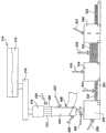
参考图5,干粘结剂(由大的箭头表示)可以在该过程中在多种不同点被添加到纤维322和/或幅材521。箭头525表示干粘结剂可以在收集构件处或上方被添加到纤维322。箭头527表示干粘结剂可以在导管330中被添加到纤维322。箭头529表示干粘结剂可以在成形设备332中被添加到纤维322。箭头531表示干粘结剂可以在幅材离开成形设备332之后被添加到幅材321。箭头533表示干粘结剂可以在幅材被分层设备334分层时被添加到幅材321。箭头535表示干粘结剂可以在分层幅材之后被添加到幅材321。箭头537表示干粘结剂可以在烤炉550中被添加到幅材321或分层的幅材。参考图8,箭头827表示干粘结剂可在导管330中在靠近成纤器的位置处被添加到纤维322。箭头829表示干粘结剂可在导管330中在导管的肘状弯部被添加到纤维322。箭头831表示干粘结剂可在导管330中在导管的出口端处被添加到纤维。箭头833表示干粘结剂可在具有滚筒形成形表面的成形设备332中被添加到纤维322。。干粘结剂可以以任何方式被添加到纤维322或幅材321以形成具有干粘结剂的幅材521。Referring to Figure 5, dry binder (indicated by large arrows) may be added to
除纤维322由积累器590收集之外,图5A是与图5的实施例类似的实施例。箭头592表示积累器590以受控方式将纤维322提供到成形设备332。在被提供到成形设备332之前,纤维322可在积累器590中停留预定时间段,以容许纤维冷却。在一个示例性实施例中,积累器590以与纤维322被提供到积累器590相同的速率将纤维322提供到成形设备332。因此,在本示例性实施例中,纤维在积累器中停留和冷却的时间由积累器中纤维322的量决定。在本例子中,停留时间等于积累器中的纤维量除以积累器将纤维提供到成形设备332的速率。在另一示例性实施例中,积累器390可选择性地开始和停止分配纤维和/或调整分配纤维的速率。可在图5所示的任何位置将干粘结剂施加到纤维322。干粘结剂可如箭头594所示地被施加到积累器中的纤维322,和/或当纤维从积累器590被传送到成形设备332时如箭头596所示地将干粘结剂施加到纤维322。FIG. 5A is an embodiment similar to that of FIG. 5 , except that
除纤维322可通过转向机构598在成形设备332和第二成形设备之间选择性地转向和/或用于一些其它应用之外,图5B是与图5的实施例类似的实施例。在一个示例性实施例中,图5所示的实施例可具有积累器590和转向机构598两者。可在图5所示的任何位置将干粘结剂施加到纤维322。干粘结剂可如箭头595所示地被施加到转向机构中的纤维322,和/或当纤维从转向机构598被传送到成形设备332时如箭头597所示地将干粘结剂施加到纤维322。FIG. 5B is an embodiment similar to that of FIG. 5 except that the
在一个示例性实施例中,在成纤器318下游较大距离处的部位,干粘结剂被施加到纤维322。例如,干粘结剂可以在纤维的温度和/或该纤维周围的空气的温度显著低于成纤器处的纤维和周围空气的温度的部位被施加到纤维。在一个示例性实施例中,在纤维的温度和/或包围纤维的空气的温度低于干粘结剂熔化的温度或干粘结剂充分固化或反应的温度的部位施加干粘结剂。例如,可以在纤维322的温度和/或包围纤维的空气的温度低于热塑性粘结剂的熔点的生产线中的点施加热塑性粘结剂。可以在纤维322的温度和/或包围纤维的空气的温度低于热固性粘结剂的固化温度的生产线中的点施加热固性粘结剂。就是说,可以在纤维322的温度和/或包围纤维的空气的温度低于热固性粘结剂充分反应或热固性粘结剂的充分交联发生的点的点施加热固性粘结剂。在一个示例性实施例中,在纤维322的温度和/或包围纤维的空气的温度低于300华氏度的生产线中的部位施加干粘结剂。在一个示例性实施例中,在纤维322的温度和/或包围纤维的空气的温度低于250华氏度的生产线中的部位施加干粘结剂。在一个示例性实施例中,在图5中由箭头527、529、531、533和535指示的部位处的纤维的温度和/或包围纤维的空气的温度低于干粘结剂熔化或充分固化的温度。In an exemplary embodiment, dry binder is applied to
在一个示例性实施例中,粘结剂敷料器是被构造用于干粉末的喷射器。该喷射器可以被构造成使得喷射的力是可调节的,因此允许干粉末更多或更少地渗透到纤维材料的连续幅材中。替代地,粘结剂敷料器可以是足以将干粘结剂卷入到玻璃纤维的连续幅材321中的其它结构、机构或装置或其组合,例如真空装置。例如,干粘结剂可包括以成捆形式提供的粘结剂纤维。粘结剂敷料器包括捆打开器和吹气机,其打开捆、将粘结剂纤维互相分离并将粘结剂纤维吹入导管,在该处粘结剂与玻璃纤维混合。干粘结剂可包括粉末。粘结剂敷料器可包括螺旋传送装置,其将粘结剂粉末传送到空气喷嘴,空气喷嘴将粘结剂粉末传送到导管,在该处粘结剂粉末与纤维混合。干粘结剂可包括非水性液体。粘结剂敷料器可包括将液态粘结剂传送到导管的喷嘴,在导管中,粘结剂与纤维混合。In one exemplary embodiment, the adhesive applicator is an applicator configured for dry powder. The injector may be configured such that the force of the injection is adjustable, thus allowing more or less penetration of the dry powder into the continuous web of fibrous material. Alternatively, the binder applicator may be another structure, mechanism, or device, or combination thereof, sufficient to entrain the dry binder into the
图9、9A和9B图示了示例性实施例,其中,利用改进的空气成网机902施加粘结剂900(诸如纤维或粉末形式、纤维形式或无水性液体形式的)。空气成网机是本领域熟知的。美国专利Nos.4,266,960;5,603,743和4,263,033以及PCT国际公布号WO 95/30036公开了空气成网机的例子,这些申请的全部内容通过引用合并于此。美国专利Nos.4,266,960;5,603,743和4,263,033以及PCT国际公布号WO 95/30036所公开的空气成网机的任何特征都可用于本专利申请示意性地说明的空气成网机902中。一个现有类型的空气成网机902是Air Full Veil Lapper(AFVL)。图9、9A和9B所示的空气成网机902与常规空气成网机的区别在于前者被配置为施加粘结剂900。Figures 9, 9A and 9B illustrate exemplary embodiments in which a binder 900 (such as in fibrous or powder form, fibrous form or anhydrous liquid form) is applied using a modified
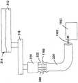
图8图示旋转成纤器318、可选的收集构件324、导管330和成形设备332。图8所示的设备通常将还包括图5所示的熔炉314和前炉316。图8中省略了熔炉314、前炉和图5所示的其他部件,以简化附图。FIG. 8 illustrates
参照图8,成形设备332可被配置为用来形成具有希望厚度的纤维材料的连续幅材321。成形设备332可以呈现很多种不同形式。可以使用用来形成玻璃纤维的干幅材321的任何布置。在图8所示的示例性实施例中,成形设备332包括旋转滚筒910,该旋转滚筒具有较高或较低压力的成形表面462和区域。利用跨越表面462的压力降ΔΡ进行的纤维收集与参照图4描述的相同。8, forming
参照图9A和9B,空气成网机902包括第一吹气机920和第二吹机器922。空气成网机通过吹气,诸如利用第一和第二吹机器920、922交替地吹气,来进行操作。吹气机920提供抵制纤维在导管中朝向成形表面462行进的空气流,而吹气机922不提供空气流(见图9A和9B)。在受控量的时间之后,吹气机922提供抵制纤维在导管中朝向成形表面462行进的空气流,而吹气机920不提供空气流。第一和第二吹气机920、922的这种交替操作使被收集在成形表面462上的纤维322均匀分布。Referring to FIGS. 9A and 9B , the
图9、9A和9B所示的空气成网机902与常规空气成网机的区别在于,吹气机920、922中的每个包括一个或多个粘结剂引入装置904。粘结剂引入装置904可呈现许多不同形式。例如,粘结剂引入装置904可将粘结剂900提供到如图所示的吹气机920、922的外壳932的内部930中,或者粘结剂引入装置可被放置为用以将粘结剂900引入吹气机920、922的空气流中。例如,粘结剂引入装置的喷嘴可将粘结剂分配到吹气机920、922的空气流中。粘结剂引入装置的例子包括但不限于喷嘴和提供比吹气机920、922少的空气流的吹气机。在一个示例性实施例中,当吹气机920或922不吹气时,粘结剂引入装置904将粘结剂900喷射到外壳932的内部930中。然后,当开启吹气机920或922时,内部930被加压并且粘结剂900从内部930被运送到纤维空气流。在空气流中,来自空气成网机的空气将会移动纤维,以对纤维在成形表面462上的分布提供成形作用,并且空气也将喷射粘结剂,以与空气流中的纤维混合。The
参照图9A和9B,空气成网机902将粘结剂900混合到聚集在成形表面462上的纤维322中,以形成幅材321。在一个示例性实施例中,当吹气机920提供抵制纤维在导管中朝向成形表面462行进的空气流921时,粘结剂引入装置904将粘结剂900引入吹气机920,并且吹气机920提供的空气流921将粘结剂与纤维322混合(如图9A和9B所示)。类似地,在本实施例中,当吹气机922提供抵制纤维在导管中朝向成形表面462行进的空气流921时,粘结剂引入装置904将粘结剂900引入吹气机922,并且吹气机922提供的空气流921将粘结剂与纤维322混合(未示出吹气机922提供的空气流,但它与吹气机920提供的空气流相同)。因此,粘结剂900与纤维322均匀地混合。9A and 9B, airlaid 902 mixes
可选的干粘结剂可以呈现很多种不同形式。可以使用将纤维322保持在一起以形成幅材521的任何无水介质。在一个示例性实施例中,干粘结剂在最初被施加到纤维时由基本上100%固体组成。如这里使用的术语“基本上100%固体”意指稀释剂(诸如水)的量小于或等于粘结剂的重量的近似2%,并且优选地小于或等于粘结剂的重量的1%(在粘结剂被施加时,而不是在粘结剂已经干燥或固化之后)的任何粘结剂材料。然而,应当理解,在某些实施例中,粘结剂可以包括根据具体应用和设计要求需要的任何量的诸如水的稀释剂。在一个示例性实施例中,干粘结剂是热塑性的基于树脂的材料,该热塑性的基于树脂的材料不以液体的形式被施加并且还不是基于水的。在其它实施例中,干粘结剂可以是其它材料或其它材料组合,包括聚合物热固性树脂的非限制性例子。干粘结剂可以具有任何形式或形式的组合,包括粉末、颗粒、纤维和/或热熔胶的非限制性例子。热熔聚合物的例子包括但不限于乙烯-醋酸乙烯酯共聚物,乙烯-丙烯酸酯共聚物,低密度聚乙烯,高密度聚乙烯,无规聚丙烯,聚丁烯-1,苯乙烯嵌段共聚物,聚酰胺,热塑性聚氨酯,苯乙烯嵌段共聚物,聚酯等等。在一个示例性实施例中,干粘结剂不是添加式甲醛干粘结剂,这是指干粘结剂不含甲醛。但是,如果燃烧不含甲醛的干粘结剂的话,可能形成甲醛。在一个示例性实施例中,施加充分的干粘结剂使得固化的纤维叠毡可以被压缩以便包装、存储和运输,然而,当被安装时重新获得其厚度-称为“松软恢复”的过程。The optional dry binder can take many different forms. Any anhydrous medium that holds
在图2A-2D和图5示出的例子中,在干粘结剂被施加到玻璃纤维之前或之后,玻璃纤维322可以可选地被涂覆或部分地涂覆有润滑剂。在示例性实施例中,在干粘结剂之后施加润滑剂以提供干粘结剂到玻璃纤维322的粘附。该润滑剂可以是任何上述润滑剂。In the example shown in FIGS. 2A-2D and 5, the
参考图5,具有未反应的干粘结剂的连续的幅材521从成形设备332被转移到可选的分层机构334。分层机构可以呈现很多种不同形式。例如,分层机构可以是沿机器方向D1分层幅材321的搭叠机构或沿基本上垂直于机器方向的方向搭叠该幅材的横向搭叠机构。用来分层无粘结剂幅材321的上述横向搭叠装置可以用于分层具有未反应的干粘结剂的幅材521。Referring to FIG. 5 , the
在示例性实施例中,连续的幅材521的干粘结剂被构造成在固化烤炉550中热凝固。在示例性实施例中,固化烤炉550取代缠结机构345,这是由于干粘结剂将纤维322保持在一起。在另一示例性实施例中,包括固化烤炉550和缠结机构345。In the exemplary embodiment, the dry binder of
图6和7示意性地示出用来从纤维材料形成叠毡的方法的另一示例性实施例(总体上以610示出)。参考图6,熔融玻璃612从熔炉614被供应到前炉616。熔融玻璃612可以由各种原材料形成,该各种原材料以一定比例组合以便给出希望的化学组成。熔融玻璃612从前炉616流到多个旋转成纤器618。6 and 7 schematically illustrate another exemplary embodiment (shown generally at 610) of a method for forming a pack from a fibrous material. Referring to FIG. 6 ,
参考图6,旋转成纤器618接收熔融玻璃612并且随后形成热气体的流中夹带的玻璃纤维622的薄片620。如下面将更详细地讨论的,由旋转成纤器618形成的玻璃纤维622是长的且细的。因此,可以使用足以形成长的且细的玻璃纤维22的任何希望的成纤器(旋转的或其它形式的)。虽然图6和7中示出的实施例示出两个旋转成纤器618,但应当理解,可以使用任何希望数量的旋转成纤器18。Referring to Figure 6, a
热气体的流可以由可选的吹气机构产生,该吹气机构诸如环形吹气机(未示出)或环形燃烧器(未示出)的非限制性例子。通常,吹气机构被构造用来沿给定方向(通常以向下的方式)引导玻璃纤维622的薄片620。应当理解,热气体的流可以由任何希望结构、机构或装置或其任何组合产生。The flow of hot gas may be produced by an optional blowing mechanism such as a non-limiting example of an annular blower (not shown) or an annular burner (not shown). Typically, the blowing mechanism is configured to direct the
如图6中所示,可选的喷射机构626可以布置在旋转成纤器618下面并且被构造用来喷射水或其它流体的微滴到薄片620中的热气体上以帮助冷却热气体的流,保护纤维622免受接触损坏且/或提高纤维622的粘结能力。喷射装置626可以是足以喷射水的微滴到薄片620中的热气体上以帮助冷却热气体的流,保护纤维622免受接触损坏且/或提高纤维622的粘结能力的任何希望结构、机构或装置。虽然图6中示出的实施例示出喷射机构626的使用,但应当理解,喷射机构626的使用是可选的,并且可以实施从纤维材料610形成叠毡的方法而不使用喷射机构626。As shown in FIG. 6, an
可选地,在玻璃纤维形成之后,玻璃纤维622可以涂覆有润滑剂。在示出的实施例中,多个喷嘴628可以在旋转成纤器618下面的位置布置在薄片620周围。喷嘴628可以被构造用来从润滑剂的源(未示出)供应润滑剂(未示出)到玻璃纤维622。Optionally, the
润滑剂的施加可以由任何希望结构、机构或装置精确控制,该任何希望结构、机构或装置诸如阀的非限制性例子(未示出)。在某些实施例中,该润滑剂可以是硅树脂化合物,诸如硅氧烷,二甲基硅氧烷和/或硅烷。该润滑剂也可以是其它材料或材料的组合,例如,油或油乳化液。该油或油乳化液可以是矿物油或矿物油乳化液和/或植物油或植物油乳化液。在示例性实施例中,润滑剂以作为结果的纤维材料的叠毡的重量的大约1.0%油和/或硅树脂化合物的量被施加。然而,在其它实施例中,润滑剂的量可以大于或小于按重量的大约1.0%油和/或硅树脂化合物。The application of lubricant can be precisely controlled by any desired structure, mechanism or device, such as a non-limiting example of a valve (not shown). In certain embodiments, the lubricant may be a silicone compound such as siloxane, dimethylsiloxane and/or silane. The lubricant can also be other materials or combinations of materials, such as oils or oil emulsions. The oil or oil emulsion may be mineral oil or mineral oil emulsion and/or vegetable oil or vegetable oil emulsion. In an exemplary embodiment, the lubricant is applied in an amount of about 1.0% oil and/or silicone compound by weight of the resulting pack of fibrous material. However, in other embodiments, the amount of lubricant may be greater or less than about 1.0% oil and/or silicone compound by weight.
虽然图6中示出的实施例示出使用喷嘴628来供应润滑剂(未示出)到玻璃纤维622,但应当理解,喷嘴628的使用是可选的,并且可以实施从纤维材料610形成叠毡的方法而不使用喷嘴628。Although the embodiment shown in FIG. 6 shows the use of
在示出的实施例中,被夹带在热气体的流内的玻璃纤维622可以被可选的收集构件624收集。收集构件624被成形且设计尺寸以容易地接收玻璃纤维622和热气体的流。收集构件624被构造用来使玻璃纤维622和热气体的流转向到导管630以便转移到下游处理站,例如,成形设备632a和632b。在其它实施例中,玻璃纤维622可以被收集在传送机构(未示出)上以便形成毯子或毛层(未示出)。该毛层可以由传送机构运输到另外的处理站(未示出)。收集构件624和导管630可以是适合于接收和传送玻璃纤维622和热气体的流的具有基本上空心的构造的任何结构。虽然图6中示出的实施例示出收集构件624的使用,但应当理解,使用收集构件624使玻璃纤维622和热气体的流转向到导管630是可选的,并且可以实施从纤维材料610形成叠毡的方法而不使用收集构件624。In the illustrated embodiment,
在图6和7中示出的实施例中,单个成纤器618与单个导管630关联,使得来自单个成纤器618的玻璃纤维622和热气体的流是进入导管630的玻璃纤维622和热气体的流的仅有的源。替代地,单个导管630可以适合于从多个成纤器618(未示出)接收玻璃纤维622和热气体的流。In the embodiment shown in FIGS. 6 and 7 , a
再次参考图6,可选地,集管系统(未示出)可以布置在成形设备632a和632b与成纤器618之间。集管系统可以构造为室,在该室中,流自多个成纤器618的玻璃纤维622和气体可以被组合,同时控制作为结果的组合的流的特性。在某些实施例中,集管系统可以包括控制系统(未示出),该控制系统被构造用来组合来自成纤器618的玻璃纤维622和气体的流并且还被构造用来将作为结果的组合的流引导到成形设备632a和632b。这种集管系统可以允许某些成纤器618的维护和清洁而不必停止剩余的成纤器618。可选地,集管系统可以包括用来控制和引导玻璃纤维22和气体流的任何希望装置。Referring again to FIG. 6 , optionally, a header system (not shown) may be disposed between the forming
现在参考图7,具有夹带的玻璃纤维622的气体的流动动量将引起玻璃纤维622继续流过导管630到成形设备632a和632b。成形设备632a和632b可以被构造用于数个功能。首先,成形设备632a和632b可以被构造用于从气体的流分离夹带的玻璃纤维622。第二,成形设备632a和632b可以被构造用来形成具有希望厚度的纤维材料的连续的薄且干的幅材。第三,成形设备632a和632b可以被构造用来以允许纤维以任何希望程度的“随机性”在幅材内取向的方式允许玻璃纤维622从气体的流分离。如这里使用的术语“随机性”被定义用来意指纤维622或纤维622的若干部分可以在X、Y或Z维度的任何中非优选地取向。在某些情况中,可能希望具有高度的随机性。在其它情况中,可能希望控制纤维622的随机性使得纤维622非随机地取向,换句话说,该纤维基本上共面的或基本上彼此平行。第四,成形设备632a和632b可以被构造用来将纤维材料的连续幅材转移到其它下游操作。Referring now to FIG. 7, the flow momentum of the gas with entrained
在图7中示出的实施例中,成形设备632a和632b的每一个包括被构造用来旋转的滚筒(未示出)。该滚筒可以包括任何希望量的较高或较低压力的成形表面和区域。替代地,成形设备632a和632b的每一个可以由其它结构、机构和装置形成,该其它结构、机构和装置足以从该气体的流分离夹带的玻璃纤维622,形成具有希望厚度的纤维材料的连续的幅材并且将纤维材料的连续幅材转移到其它下游操作。在图7中所示的示出的实施例中,成形设备632a和632b的每一个是相同的。然而,在其它实施例中,成形设备632a和632b的每一个可以彼此不同。In the embodiment shown in FIG. 7, each of the forming
再次参考图7,纤维材料的连续幅材从成形设备632a和632b被转移到可选的粘结剂敷料器646。粘结剂敷料器646被构造用来施加“干粘结剂”到纤维材料的连续幅材。如这里使用的术语“干粘结剂”被定义用来意指在施加该粘结剂时该粘结剂由基本上100%固体组成。如这里使用的术语“基本上100%固体”被定义用来意指稀释剂(诸如水)的量小于或等于粘结剂的重量的近似2%,并且优选地小于或等于粘结剂的重量的近似1%(在粘结剂被施加时,而不是在粘结剂已经干燥且/或固化之后)的任何粘结剂材料。然而,应当理解,在某些实施例中,粘结剂可以包括根据具体应用和设计要求需要的任何量的诸如水的稀释剂。该粘结剂可以被构造用来在固化烤炉650中热凝固。在本申请中,术语“固化”和“热凝固”指的是引起干粘结剂将幅材的纤维粘结在一起的化学反应和/或一个或更多个相变。例如,热固性干粘结剂(或干粘结剂的热固性成分)由于化学反应(由于热的施加而发生)而固化或热凝固。热塑性干粘结剂(或干粘结剂的热塑性成分)由于被加热到软化或熔化相并且随后冷却到固相而固化或热凝固。Referring again to FIG. 7 , the continuous web of fibrous material is transferred from the forming
在示例性实施例中,干粘结剂是热塑性的基于树脂的材料,该热塑性的基于树脂的材料不以液体的形式被施加并且还不是基于水的。在其它实施例中,干粘结剂可以是其它材料或其它材料组合,包括聚合物热固性树脂的非限制性例子。干粘结剂可以具有任何形式或包括粉末,颗粒,纤维和/或热熔胶的非限制性例子的形式的组合。热熔聚合物的例子包括但不限于乙烯-醋酸乙烯酯共聚物,乙烯-丙烯酸酯共聚物,低密度聚乙烯,高密度聚乙烯,无规聚丙烯,聚丁烯-1,苯乙烯嵌段共聚物,聚酰胺,热塑性聚氨酯,苯乙烯嵌段共聚物,聚酯等等。施加充分的干粘结剂使得固化的纤维叠毡可以被压缩以便包装、存储和运输,然而,当被安装时重新获得其厚度-称为“松软恢复”的过程。施加干粘结剂到纤维材料的连续幅材形成可选地具有未反应的粘结剂的连续的幅材。In an exemplary embodiment, the dry binder is a thermoplastic resin-based material that is not applied in liquid form and is not yet water-based. In other embodiments, the dry binder may be other materials or other combinations of materials, including non-limiting examples of polymeric thermoset resins. The dry binder can be in any form or combination including powders, granules, fibers and/or non-limiting examples of hot melt adhesives. Examples of hot melt polymers include, but are not limited to, ethylene-vinyl acetate copolymers, ethylene-acrylate copolymers, low density polyethylene, high density polyethylene, random polypropylene, polybutene-1, styrene blocks Copolymers, polyamides, thermoplastic polyurethanes, styrene block copolymers, polyesters and more. Sufficient dry binder is applied so that the cured fiber pack can be compressed for packaging, storage and shipping, however, regain its thickness when installed - a process known as "fluff recovery". The application of dry binder to the continuous web of fibrous material forms a continuous web, optionally with unreacted binder.
在图6和7示出的实施例中,粘结剂敷料器646是被构造用于干粉末的喷射器。该喷射器被构造成使得喷射的力是可调节的,因此允许干粉末更多或更少地渗透到纤维材料的连续幅材中。替代地,粘结剂敷料器646可以是足以将“干粘结剂”卷入到纤维材料的连续幅材中的其它结构、机构或装置或其组合,例如真空装置。In the embodiment shown in Figures 6 and 7, the adhesive applicator 646 is an injector configured for dry powder. The injector is configured such that the force of the injection is adjustable, thus allowing more or less penetration of the dry powder into the continuous web of fibrous material. Alternatively, the binder applicator 646 may be other structure, mechanism, or device, or combination thereof, sufficient to entrain the "dry binder" into the continuous web of fibrous material, such as a vacuum device.
虽然图7中示出的实施例示出被构造用来施加干粘结剂到纤维材料的连续幅材的粘结剂敷料器646,但在本发明的预期内的是,在某些实施例中,将不施加粘结剂到纤维材料的连续幅材。Although the embodiment shown in FIG. 7 shows a binder applicator 646 configured to apply dry binder to a continuous web of fibrous material, it is within the contemplation of the present invention that in certain embodiments , no binder will be applied to the continuous web of fibrous material.
再次参考图7,可选地具有未反应的粘结剂的连续的幅材从粘结剂敷料器646被转移到对应的横向搭叠机构634a和634b。如图7中所示,成形设备632a与横向搭叠机构634a关联并且成形设备632b与横向搭叠机构634b关联。横向搭叠机构634a和634b与第一传送器636关联地起作用。第一传送器636被构造用来沿如箭头D1指示的机器方向移动。横向搭叠机构634a被构造用来从可选的粘结剂敷料器646接收可选地具有未反应的粘结剂的连续的幅材,并且还被构造用来在第一传送器636沿机器方向D1移动时将可选地具有未反应的粘结剂的连续幅材的交替的层存放在第一传送器636上,因此形成纤维体的最初层。在存放过程中,横向搭叠机构634a沿如箭头D2指示的横穿机器方向形成交替的层。因此,在可选地具有未反应的粘结剂的存放的连续幅材从横向搭叠机构634a沿机器方向D1行进时,另外的层被下游的横向搭叠机构634b存放在该纤维体上。由横向搭叠机构634a和634b存放的作为结果的纤维体的层形成叠毡。Referring again to Figure 7, the continuous web, optionally with unreacted adhesive, is transferred from adhesive applicator 646 to corresponding
在示出的实施例中,横向搭叠机构634a和634b是如下装置,该装置被构造用来精确地控制具有未反应的粘结剂的连续的幅材的移动并且将具有未反应的粘结剂的该连续的幅材存放在第一传送器636上使得可选地具有未反应的粘结剂的连续的幅材不被损坏。横向搭叠机构634a和634b可以包括任何希望结构并且可以被构造用来以任何希望方式进行操作。在一个例子中,横向搭叠机构634a和634b可以包括头部(未示出),该头部被构造用来沿横穿机器方向D2来回移动。在这个实施例中,协调移动头部的速度使得沿两个机器横穿机器方向的头部的移动基本上相同,因此提供作为结果的纤维体的层的一致性。在另一例子中,可以使用构造成以第一传送器636的中心线为中心的竖直传送器(未示出)。竖直传送器还被构造成从第一传送器636上方的枢轴机构悬挂以便将可选地具有未反应的粘结剂的连续幅材存放在第一传送器36上。虽然上面已经描述横向搭叠机构的数个例子,但应当理解,横向搭叠机构634a和634b可以是其它结构,机构或装置或其组合。In the illustrated embodiment, the
再次参考图7,可选地,在第一传送器636上的可选地具有未反应的粘结剂的连续幅材的布置可以由控制器(未示出)实现,以便提供该叠毡的提高的一致性。该控制器可以是任何希望结构,机构或装置或其组合。Referring again to Figure 7, optionally, the arrangement of the continuous web, optionally with unreacted binder, on the
分层的幅材或叠毡可以具有任何希望厚度。该叠毡的厚度根据多个变量而定。首先,该叠毡的厚度根据由成形设备632a和632b的每一个形成的可选地具有未反应的粘结剂的连续幅材的厚度而定。第二,该叠毡的厚度根据横向搭叠机构634a和634b交替地将可选地具有未反应的粘结剂的连续幅材的层存放在第一传送器636上的速度而定。第三,该叠毡的厚度根据第一传送器636的速度而定。在示出的实施例中,该叠毡具有从大约2.54毫米(0.1英寸)到大约508毫米(20.0英寸)的范围中的厚度。在其它实施例中,该叠毡可以具有小于大约2.54毫米(0.1英寸)或大于大约508毫米(20.0英寸)的厚度。The layered web or pack can have any desired thickness. The thickness of the pack depends on a number of variables. First, the thickness of the pack depends on the thickness of the continuous web, optionally with unreacted binder, formed by each of the forming
如上面讨论的,横向搭叠机构634a和634b被构造用来在第一传送器636沿机器方向D1移动时将可选地具有未反应的粘结剂的连续幅材的交替的层存放在第一传送器636上,因此形成纤维体的层。在示出的实施例中,协调横向搭叠机构634a和634b以及第一传送器636以便形成纤维体,该纤维体具有从大约1层到大约60层的范围中的层数。在其它实施例中,可以协调横向搭叠机构634a和634b和第一传送器636以便形成具有任何希望层数的纤维体(包括具有超过60层的纤维体)。As discussed above, the
可选地,横向搭叠机构634a和634b可以是可调节的,因此允许横向搭叠机构634a和634b形成具有任何希望宽度的叠毡。在某些实施例中,该叠毡可以具有从大约2489.2毫米(98.0英寸)到大约5994.4毫米(236.0英寸)的范围中的总宽度。替代地,该叠毡可以具有小于大约2489.2毫米(98.0英寸)或大于大约5994.4毫米(236.0英寸)的总宽度。Optionally, the
虽然横向搭叠机构634a和634b已经在上面被描述为被共同地包括在纤维体的形成中,但应当理解,在其它实施例中,横向搭叠机构634a和634b可以彼此独立地操作以便形成纤维体的分离的条材(lane)。Although the
参考图6和7,具有由横向搭叠机构634a和634b形成的层的叠毡由第一传送带636运送到可选的修剪机构640。可选的修剪机构640被构造用来修剪叠毡的边缘,以便形成希望宽度的叠毡。在示例性实施例中,该叠毡可以具有从大约2489.2毫米(98.0英寸)到大约5994.4毫米(236.0英寸)的范围中的修剪后宽度。替代地,该叠毡可以具有小于大约2489.2毫米(98.0英寸)或大于大约5994.4毫米(236.0英寸)的修剪后宽度。Referring to Figures 6 and 7, a pack having layers formed by
在示出的实施例中,可选的修剪机构640包括锯系统,该锯系统具有布置在该叠毡的任一侧上的多个旋转锯(未示出)。替代地,修剪机构640可以是其它结构、机构或装置或其组合(包括水射流压缩刀的非限制性例子)。In the illustrated embodiment, the
在示出的实施例中,修剪机构640有利地布置在固化烤炉650上游。将修剪机构640布置在固化烤炉650上游允许该叠毡在该叠毡在固化烤炉650中热凝固之前被修剪。可选地,由修剪机构640从该叠毡修剪的材料可以返回到导管630中的气体和玻璃纤维流并且在成形设备632a和632b中被回收。修剪材料的回收有利地防止与修剪材料的处置关联的潜在的环境问题。如图6中所示,导管系统642将修剪机构640与导管630连接并且被构造用来促进修剪材料返回到成形设备632a和632b。虽然图6和7中示出的实施例示出修剪材料的回收,但应当理解,修剪材料的回收是可选的并且可以实施从纤维材料610形成叠毡的方法而不回收修剪材料。在另一示例性实施例中,修剪机构640布置在固化烤炉650下游。如果不回收修剪材料,则这种布置是特别有用的。修剪该叠毡形成修剪的叠毡。In the illustrated embodiment, the
修剪的叠毡被第一传送器636传送到第二传送器644。如图6中示出的,第二传送器644可以布置成从第一传送器636“阶梯下降”。如这里使用的术语“阶梯下降”被定义用来意指第二传送器644的上表面布置成竖直地在第一传送器636的上表面下方。传送器的阶梯下降将在下面被更详细地讨论。The trimmed pack is conveyed by the
再次参考图1和2,修剪的叠毡由第二传送器644运送到可选的缠结机构645。缠结机构645被构造用来缠结形成修剪的叠毡的层的单个纤维622。缠结该叠毡内的玻璃纤维622将该叠毡束缚在一起。在包括干粘结剂的实施例中,缠结玻璃纤维622有利地允许例如抗张强度和剪切强度的机械性质被改善。在示出的实施例中,缠结机构645是针刺机构。在其它实施例中,缠结机构645可以包括其它结构、机构或装置或其组合(包括缝合机构的非限制性例子)。虽然图6和7中示出的实施例示出缠结机构645的使用,但应当理解,缠结机构645的使用是可选的,并且可以实施从纤维材料610形成叠毡的方法而不使用缠结机构645。缠结该叠毡内的纤维形成缠结的叠毡。Referring again to FIGS. 1 and 2 , the trimmed pack is conveyed by a
第二传送器644将可选地修剪的且/或可选地缠结的具有可选的干粘结剂的叠毡(下面,修剪的叠毡和缠结的叠毡都简称为“叠毡”)传送到第三传送器648。当该叠毡包括干粘结剂时,第三传送器648被构造用来将该叠毡运送到可选的固化烤炉650。固化烤炉650被构造用来将流体(例如,加热的空气)吹过该叠毡以便固化干粘结剂并且以基本上随机的三维结构将玻璃纤维622刚性地粘结在一起。在固化烤炉650中固化该叠毡形成固化的叠毡。The
如上面讨论的,该叠毡可选地包括干粘结剂。干粘结剂(而不是传统的湿粘结剂)的使用有利地允许固化烤炉650使用较少的能量来固化该叠毡内的干粘结剂。在示出的实施例中,与常规固化烤炉用于固化湿的或含水的粘结剂的能量相比,在固化烤炉650中的干粘结剂的使用导致从大约30.0%到大约80.0%的范围中的能量节省。在又一其它实施例中,能量节省可以超过80.0%。固化烤炉650可以是任何希望固化结构、机构或装置或其组合。As discussed above, the pack optionally includes a dry binder. The use of a dry binder (rather than a traditional wet binder) advantageously allows the curing
第三传送器648将固化的叠毡传送到第四传送器652。第四传送器652被构造用来将固化的叠毡运送到切割机构654。可选地,切割机构654可以被构造用于数种切割模式。在第一可选切割模式中,切割机构被构造用来在沿机器方向D1的竖直方向上切割固化的叠毡以便形成条材。形成的条材可以具有任何希望宽度。在第二可选切割模式中,切割机构被构造用来沿水平方向平分固化的叠毡以便形成具有数个厚度的连续的叠毡。作为结果的平分的叠毡可以具有任何希望厚度。切割固化的叠毡形成切割的叠毡。The
在示出的实施例中,切割机构654包括锯和刀的系统。替代地,切割机构654可以是其它结构、机构或装置或其组合。再次参考图6和7,切割机构654有利地布置成以便允许在切割操作期间形成的粉尘和其它废料的俘获。可选地,来自于切割机构的粉尘和其它废料可以返回到导管630中的气体和玻璃纤维流并且在成形设备632a和632b中被回收。粉尘和废料的回收有利地防止与粉尘和废料的处置关联的潜在的环境问题。如图6和7中所示,导管系统655将切割机构654与导管630连接并且被构造用来促进粉尘和废料返回到成形设备632a和632b。虽然图6和7中示出的实施例示出粉尘和废料的回收,但应当理解,粉尘和废料的回收是可选的并且可以实施从纤维材料10形成叠毡的方法而不回收粉尘和废料。In the illustrated embodiment, the
可选地,在将固化的叠毡传送到切割机构654之前,固化的叠毡的主表面可以由饰面机构662a、662b用一种或多种饰面材料饰面,如图6中所示。在示出的实施例中,固化的叠毡的上主表面用饰面机构662a提供的饰面材料663a被饰面,并且固化的叠毡的下主表面用饰面机构662b提供的饰面材料663b被饰面。饰面材料可以是任何希望材料,包括纸、聚合物材料或非纺织幅材。饰面机构662a和662b可以是任何希望结构,机构或装置或其组合。在示出的实施例中,饰面材料663a和663b通过粘合剂被施加到固化的叠毡(如果该叠毡包括粘结剂)。在其它实施例中,饰面材料663a和663b可以通过其它方法(包括声波焊接的非限制性例子)被施加到固化的叠毡。虽然图6中示出的实施例示出将饰面材料663a和663b施加到固化的叠毡的主表面,但应当理解,将饰面材料663a和663b施加到固化的叠毡的主表面是可选的,并且可以实施从纤维材料610形成叠毡的方法而不施加饰面材料663a和663b到固化的叠毡的主表面。Optionally, prior to conveying the cured pack to cutting
参考图6和7,第四传送器652将切割的叠毡传送到可选的截断机构656。截断机构656被构造用来横穿机器方向D1将切割的叠毡分割成希望的段。在示出的实施例中,截断机构656被构造用来在切割的叠毡沿机器方向D1连续移动时分割切割的叠毡。替代地,截断机构656可以被构造用于成批截断操作。将切割的叠毡分割成数个段形成确定尺寸的叠毡。截断的叠毡的段可以具有任何希望尺寸。Referring to FIGS. 6 and 7 , a
截断机构在该技术领域中是已知的并且在这里将不被描述。该截断机构656可以是任何希望结构、机构或装置或其组合。Truncation mechanisms are known in the art and will not be described here. The
可选地,在将切割的叠毡传送到截断机构656之前,切割的叠毡的次表面可以由饰边机构666a、666b用一种或多种饰边材料饰面,如图7中所示。饰边材料可以是任何希望材料,包括纸、聚合物材料或非纺织幅材。饰边机构666a和666b可以是任何希望结构、机构或装置或其组合。在示出的实施例中,饰边材料667a和667b通过粘合剂被施加到切割的叠毡。在其它实施例中,饰边材料667a和667b可以通过其它方法(包括声波焊接的非限制性例子)被施加到切割的叠毡。虽然图7中示出的实施例示出将饰边材料667a和667b施加到切割的叠毡的次表面,但应当理解,将饰边材料667a和667b施加到切割的叠毡的次表面是可选的,并且可以实施从纤维材料610形成叠毡的方法而不施加饰边材料667a和667b到切割的叠毡的次表面。Optionally, the subsurfaces of the cut pack may be veneered with one or more trim materials by
再次参考图6,第四传送器652将确定尺寸的叠毡传送到第五传送器658。第五传送器658被构造用来将确定尺寸的叠毡传送到包装机构660。包装机构660被构造用来包装确定尺寸的叠毡以便将来操作。如这里使用的术语“将来操作”被定义用来包括形成确定尺寸的叠毡之后的任何行动(包括存储,运输、销售和安装的非限制性例子)。Referring again to FIG. 6 , the
在示出的实施例中,包装机构660被构造用来将确定尺寸的叠毡形成为呈卷材的形式的封装。在其它实施例中,包装机构660可以形成具有其它希望形状的封装,诸如厚片、毛层和不规则地成形或模切的块的非限制性例子。包装机构660可以是任何希望结构、机构或装置或其组合。In the illustrated embodiment, the
再次参考图6,传送器636、644、648、652和658处于沿机器方向D1“阶梯下降”关系。“阶梯下降”关系意指后续传送器的上表面布置成竖直地在先前传送器的上表面下方。传送器的“阶梯下降”关系有利地为叠毡的传送提供自穿过特征。在示出的实施例中,相邻传送器之间的竖直偏移在从大约76.2毫米(3.0英寸)到大约254毫米(10.0英寸)的范围中。在其它实施例中,相邻传送器之间的竖直偏移可以小于大约76.2毫米(3.0英寸)或大于大约254毫米(10.0英寸)。Referring again to FIG. 6, the
如图6和7中所示,用来从纤维材料610形成叠毡的方法消除湿粘结剂的使用,因此消除对洗涤水和洗涤水相关结构(诸如成形罩、返回泵和管道系统)的传统需要。水(除了冷却水外)的使用的消除和润滑剂、颜料和其它可选化学物质的施加有利地允许制造线(或“占地面积”)的总尺寸显著减小,以及减小实施成本、操作成本和维护和维修成本。As shown in Figures 6 and 7, the method used to form a pack from
如图6和7中另外示出的,用来从纤维材料610形成叠毡的方法有利地允许均匀地且一致地存放长的且细的纤维在成形设备632a和632b上。在示出的实施例中,纤维622具有从大约6.35毫米(0.25英寸)到大约254毫米(10.0英寸)的范围中的长度和从大约9HT到大约35HT的范围中的直径尺寸。在其它实施例中,纤维22具有从大约25.4毫米(1.0英寸)到大约127毫米(5.0英寸)的范围中的长度和从大约14HT到大约25HT的范围中的直径尺寸。在又一其它实施例中,纤维22可以具有小于大约6.35毫米(0.25英寸)或大于大约254毫米(10.0英寸)的长度和小于大约9HT或大于大约35HT的直径尺寸。虽然不受理论约束,但相信,相对长的且细的纤维的使用有利地提供具有更好热和声学绝缘性能的叠毡(与具有较短且较厚纤维的类似尺寸的叠毡相比)。As additionally shown in Figures 6 and 7, the method used to form a pack from
虽然图6和7中示出的实施例在上面已经一般地被描述用来形成纤维材料的叠毡,但应当理解,相同的设备可以被构造用来形成“不粘结的松散填充的隔热体”。如这里使用的术语“不粘结的松散填充的隔热体”被定义用来意指被构造用于空气流中的应用的任何条件的隔热材料。While the embodiments shown in Figures 6 and 7 have been described above generally for forming packs of fibrous material, it should be understood that the same apparatus may be configured to form "unbonded loose-fill thermal insulation" body". The term "unbonded loose-fill insulator" as used herein is defined to mean an insulating material constructed for any condition of application in air flow.
虽然上面已经一般地描述叠毡和用来从纤维材料610形成叠毡的方法的示例性实施例,但应当理解,方法610的其它实施例和变体是可用的并且将在下面被一般地描述。While exemplary embodiments of packs and methods for forming packs from
参考图7,在方法610的另一实施例中,横向搭叠机构634a和634b被构造用来提供在第一传送器36上的连续幅材的交替的层的精确存放,因此允许消除下游修剪机构40。Referring to FIG. 7, in another embodiment of
再次参考图7,在方法610的另一实施例中,该叠毡的各种层可以是“成层次的”。如这里使用的术语“成层次的”被定义用来意指该层的每一个和/或层的一些部分可以构造有不同的特性,该不同的特性包括纤维直径、纤维长度、纤维取向、密度、厚度和玻璃组成的非限制性例子。可以预期,形成层的相关机构,即相关的成纤器、成形设备和横向搭叠机构可以被构造用来提供具有特定的且希望的特性的层和/或层的一些部分。因此,叠毡可以由具有不同特性的层和/或层的一些部分形成。Referring again to FIG. 7, in another embodiment of
图10A-10C图示了包括一个或多个厚的低密度芯体1002和一个或多个薄的高密度可拉伸层1004的隔热产品1000的示例性实施例。厚的低密度芯体1002可呈现各种不同的形式。例如,低密度芯体1002可由任何上述低面积重量的叠毡制成。在一个示例性实施例中,低密度芯体1002由针刺和/或分层的玻璃纤维制成。在一个示例性实施例中,低密度芯体1002是无粘结剂的。在另一示例性实施例中,低密度芯体的纤维322通过粘结剂粘结在一起。FIGS. 10A-10C illustrate an exemplary embodiment of an insulating
薄的高密度可拉伸层1004可呈现各种不同形式。在一个示例性实施例中,薄的高密度可拉伸层1004由被针刺在一起的玻璃纤维制成。但是,可利用其他过程和/或产品处理高密度可拉伸层1000的纤维,以获得合适的抗张强度。在一个示例性实施例中,高密度可拉伸层1004由图3D实施例的高密度叠毡300制成。The thin high density
在示例性实施例中,高密度可拉伸层1004被附接到低密度芯体1002。可用各种不同的方式将高密度可拉伸层1004附接到低密度芯体1002。例如,可利用粘合剂、通过额外的针刺步骤、通过热粘结(当层1002、1004中的一个或两者包括粘结剂时)等,将层1002、1004附接到彼此。可采用将层附接到彼此的任何方法。在示例性实施例中,层1002、1004为隔热产品1000提供独特的性质。In the exemplary embodiment, the high density
在示例性实施例中,厚的低密度层1002提供高热阻值R,但具有低抗张强度,并且薄的高密度可拉伸层1004提供低热阻值R,但具有高抗张强度。两个层的结合为隔热产品1000提供了高抗张强度和高R值两者。In an exemplary embodiment, the thick
图10D-10F图示了包括一个或多个厚的低密度芯体1002和一个或多个薄的饰面层1004的隔热产品1000的示例性实施例。厚的低密度芯体1002可呈现各种不同的形式,如参照图10A-10C所示的实施例描述的。饰面层1004可呈现各种不同的形式。可选择饰面层1004的材料,以为隔热产品提供各种不同的性质。例如,可选择饰面材料,以为隔热材料提供希望大小的强度、反射率、声学特性、防水性和/或防水蒸气性。饰面层可由各种不同材料制成,包括但不限于塑料、金属薄片、薄棉布、纸、这些材料的结合等。可使用任何已知的饰面层。FIGS. 10D-10F illustrate an exemplary embodiment of an insulating
在示例性实施例中,饰面层1004被附接到低密度芯体1002。可用各种不同的方式将饰面层1004附接到低密度芯体1002。例如,可利用粘合剂、通过热粘结等将层1002、1004附接到彼此。可采用将层附接到彼此的任何方法。在示例性实施例中,层1002、1004为隔热产品1000提供独特的性质。在示例性实施例中,厚的低密度层1002提供高热阻值R,但具有低抗张强度,并且饰面层1004提供抗张强度和其他性质。In the exemplary embodiment, facing
根据具有不同密度的子层(strata)描述图10G-10I所示的例子。但是,子层可具有不同的性质,其可以也可以不包括不同密度。可通过改变穿过叠毡厚度的纤维密度、纤维长度、纤维直径和/或纤维类型来获得这些变化的性质。图10G-10I图示包括一个或多个低密度子层1052和一个或多个高密度子层1054的分层次的毛层或叠毡1050的示例性实施例。但是,低密度子层1052和高密度子层1054之间的过渡可以是渐进的。在图10A-10F所示的例子中,隔热产品1000由分离的层形成。在图10G-10I所示的示例性实施例中,分层次的毛层或叠毡1050形成为沿毛层或叠毡的厚度具有变化的性质。低密度子层1052可呈现各种不同的形式。例如,低密度子层1052可按与制造上述低面积重量叠毡相同的方式制成。在一个示例性实施例中,低密度子层1052可由玻璃纤维制成。在一个示例性实施例中,低密度子层1052是无粘结剂的。在另一示例性实施例中,低密度子层1052的纤维322通过粘结剂粘结在一起。The examples shown in FIGS. 10G-10I are described in terms of strata having different densities. However, the sublayers may have different properties, which may or may not include different densities. These varied properties can be achieved by varying the fiber density, fiber length, fiber diameter and/or fiber type through the thickness of the pack. FIGS. 10G-10I illustrate an exemplary embodiment of a layered batt or
薄的高密度子层1054可呈现各种不同形式。在一个示例性实施例中,高密度子层1054由被针刺在一起的玻璃纤维制成。但是,可利用其他过程和/或产品处理高密度子层1054的纤维,以获得合适的抗张强度。在一个示例性实施例中,高密度子层1054由与制造图3D实施例的高密度叠毡300相同的方式制成。The thin
在示例性实施例中,高密度子层1054的纤维可附接到低密度子层1052的纤维和/或与其缠结。高密度子层1054的纤维可按各种不同方式附接到低密度子层1052的纤维。例如,可利用粘合剂,诸如被施加到叠毡的粘结剂,和/或通过在制造叠毡1050时执行的针刺等,将子层1002、1004的纤维附接到彼此。可采用附接和/或缠结子层1052、1054的纤维的任何方法。在示例性实施例中,子层1052、1054为隔热产品1000提供独特的性质。In an exemplary embodiment, the fibers of the
图10A-10I的实施例的隔热毛层、叠毡和产品可互相结合在一起。例如,图10A-10F所示的隔热产品的任何层可被分层次,图10G-10I的分层次的毛层或叠毡可设置有一个或多个饰面层或分离的致密层,等等。利用图10A-10I所示的实施例可构造各种不同的隔热配置。The insulating batts, packs and products of the embodiments of Figures 10A-10I may be combined with each other. For example, any of the layers of the insulating product shown in Figures 10A-10F can be layered, the layered batts or batts of Figures 10G-10I can be provided with one or more facing layers or separate dense layers, etc. Wait. A variety of different thermal insulation configurations can be constructed using the embodiments shown in Figures 10A-10I.
在示例性实施例中,厚的低密度子层1052提供高热阻值R,但具有低抗张强度,并且薄的高密度可拉伸子层1004提供低热阻值R,但具有高抗张强度。两个子层的结合为毛层或叠毡1050提供了高抗张强度和高R值两者。子层可被配置成为毛层或叠毡提供各种不同的性质。例如,交替的薄的高密度和厚的低密度子层致使毛层或叠毡具有优异的声学性质。In an exemplary embodiment, the thick
在一个实施例中,干粘结剂可以包括或涂覆有添加剂以赋予该叠毡希望的特性。添加剂的一个非限制性例子是阻燃材料,例如烘焙苏打。添加剂的另一非限制性例子是禁止紫外光穿过该叠毡的材料。添加剂的又一非限制性例子是禁止红外光穿过该叠毡的材料。In one embodiment, the dry binder may include or be coated with additives to impart desired properties to the pack. A non-limiting example of an additive is a flame retardant material such as baking soda. Another non-limiting example of an additive is a material that inhibits UV light from passing through the pack. Yet another non-limiting example of an additive is a material that inhibits infrared light from passing through the pack.
参考图6,在方法610的另一实施例中并且如上面讨论的,热气体的流可以由可选的吹气机构产生,该吹气机构诸如环形吹气机(未示出)或环形燃烧器(未示出)的非限制性例子。已知在该技术领域中将环形吹气机和环形燃烧器产生的热称为“纤维化的热”。在这个实施例中可以预期,纤维化的热被俘获并且回收以便用于其它机构或装置。在方法610中,纤维化的热可以在数个部位被俘获。如图6和7中所示,导管系统670被构造用来俘获从成纤器618发出的热并且传送该热以便用于其它机构,例如,可选的固化烤炉650。类似地,导管系统672被构造用来俘获从导管30内的热气体的流发出的热并且导管系统674被构造用来俘获从成形设备632a和632b发出的热。回收的热也可以用于除了纤维叠毡的形成外的目的,例如,加热孔口。Referring to FIG. 6, in another embodiment of
在某些实施例中,导管630可以包括热俘获装置,例如热提取固定装置,该热提取固定装置被构造用来俘获热而不显著干涉热气体和夹带的玻璃纤维622的流动动量。在其它实施例中,可以使用足以俘获纤维化的热的任何希望结构、装置或机构。In certain embodiments, the
参考图6,在方法610的另一实施例中,具有其它希望特性的纤维或其它材料可以与气体的流中夹带的玻璃纤维622混合。在这个实施例中,可以设置其它材料(例如,合成的或陶瓷的纤维,着色剂和/或颗粒)的源676以允许这种材料被引入到导管678中。Referring to Figure 6, in another embodiment of
导管678可以连接到导管630以便允许与气体的流中夹带的玻璃纤维622混合。以这种方式,作为结果的叠毡的特性可以被设计或定制以便希望的性质,诸如声学、热增强或UV阻止特性的非限制性例子。
在又一其它实施例中,可以预期,其它材料可以布置在由横向搭叠机构634a和634b存放在第一传送器636上的层之间。该其它材料可以包括:片材材料,该片材材料例如饰面材料、蒸汽屏蔽层或网;或其它非片材材料,该其它非片材材料包括粉末、颗粒或粘合剂的非限制性例子。该其它材料可以以任何希望方式布置在该层之间。以这种方式,在希望时可以进一步设计或定制作为结果的叠毡的特性。In yet other embodiments, it is contemplated that other materials may be disposed between the layers deposited on the
虽然图6中示出的实施例示出由粘结剂敷料器646施加干粘结剂,但应当理解,在其它实施例中,干粘结剂可以被施加到气体的流中夹带的玻璃纤维622。在这个实施例中,干粘结剂的源680可以被引入到导管682中。导管682可以连接到导管630以便允许干粘结剂与气体的流中夹带的玻璃纤维622混合。干粘结剂可以被构造用来以任何希望方式(包括通过静电处理)附着到玻璃纤维。Although the embodiment shown in FIG. 6 shows the application of dry adhesive by adhesive applicator 646, it should be understood that in other embodiments dry adhesive may be applied to
虽然图6中示出的实施例示出由横向搭叠机构634a和634b使用连续的幅材,但应当理解,在其它实施例中,该幅材可以从成形设备632a和632b被移除且存储以便以后使用。Although the embodiment shown in FIG. 6 shows the use of a continuous web by the
如上面讨论的,可选地,修剪的材料可以返回到导管630中的气体和玻璃纤维流并且在成形设备632a和632b中被回收。在示例性实施例中,当可选的粘结剂被包括在该叠毡中时,成形设备332a和332b的操作温度被保持在干粘结剂的软化温度之下,因此防止干粘结剂在固化烤炉550的下游操作之前固化。在这个实施例中,固化烤炉650的最大操作温度在从大约73.9℃(165℉)到大约82.2℃(180℉)的范围中。在其它实施例中,固化烤炉650的最大操作温度可以小于大约73.9℃(165℉)或大于大约82.2℃(180℉)。As discussed above, the trimmed material can optionally be returned to the gas and glass fiber flow in
在一个示例性实施例中,这里描述的长薄纤维322可用于除上述外的其他应用。例如,图11图示了上述长薄纤维322可被提供作为短纤维,其经气流成网、梳理或以其他方式被处理以便用于各种不同的应用,而不是形成为幅材和、或叠毡。在一个应用中,未粘结的短纤维与芳纶纤维(诸如Kevlar和Konex)混合和/或与热粘结纤维(诸如Celbond)混合。这些混合纤维可用于形成短纤维纱和/或干法成网无纺材料。In an exemplary embodiment, the long
在图11中,熔炉314将熔融玻璃312供应到前炉316。处理熔融玻璃312以形成玻璃纤维322。可用各种不同方式处理熔融玻璃312以形成玻璃纤维322。例如,旋转成纤器318接收熔融玻璃312,随后形成玻璃纤维322的薄片320。可使用足以形成长薄玻璃纤维322的任何希望的成纤器,旋转的或其它形式的。In FIG. 11 ,
参照图11,敷料器1100将润滑剂(也被称作胶料)施加到未粘结的玻璃纤维。在所示实施例中,胶料在成纤器下方被施加到玻璃纤维。但是,在其它实施例中,胶料可在其他位置,诸如导管330中,被施加到玻璃纤维。胶料增强纤维和/或润滑纤维,这有助于纤维的处理,诸如,纤维的针刺或梳理。未粘结的短纤维322被设置在导管330的出口处,如箭头1102所示,在该处,纤维被收集在容器1103中,以便单独地或与其他纤维(诸如芳纶纤维)结合地用于各种不同的应用。Referring to Figure 11, an
胶料可呈现各种不同的形式。例如,胶料可包括硅树脂和/或硅烷。但是,根据应用,可采用任何胶料。可基于玻璃纤维将用于的应用,调整胶料。Compounds can take on a variety of different forms. For example, the sizing can include silicone and/or silane. However, depending on the application, any compound can be used. The compound can be adjusted based on the application the glass fiber will be used for.
小的纤维直径和长的纤维长度容许经该尺寸改变的纤维用于纤维之前因纤维的过量破损而不能用于的应用。在一个示例性实施例中,相比常规纤维,直径约为4微米的纤维322具有更好的挠曲模量和所得强度,因为更细的纤维更容易在不破损的情况下弯曲。此改进的纤维的挠曲模量和强度帮助纤维成功承受对常规纤维来说通常是毁灭性的过程,诸如梳理和气流成网过程。此外,玻璃纤维的小直径改进了热和声学性质两者。The small fiber diameter and long fiber length allow the size-modified fibers to be used in applications where the fibers were previously unusable due to excessive fiber breakage. In an exemplary embodiment,
玻璃幅材、叠毡和短纤维可用于各种不同的应用。应用的例子包括但不限于加热器具(诸如烤炉、炉灶和热水器)、暖通空调(HVAC)部件(诸如HVAC导管)、隔音板和材料(诸如用于建筑和/或车辆的隔音板)和模塑玻璃纤维部件(诸如压缩模塑或真空模塑玻璃纤维部件)。在一个示例性实施例中,加热器具(诸如烤炉、炉灶和热水器)、HVAC部件(诸如HVAC导管)、隔音板和材料(诸如用于建筑和/或车辆的隔音板)和/或模塑玻璃纤维部件(诸如压缩模塑或真空模塑玻璃纤维部件)使用根据本专利申请所公开的实施例中的一个或多个制造的无粘结剂玻璃纤维叠毡或由其制成。在示例性实施例中,由于玻璃纤维叠毡是无粘结剂的,因此玻璃纤维叠毡中不存在甲醛。在一个示例性实施例中,加热器具(诸如烤炉、炉灶和热水器)、HVAC部件(诸如HVAC导管)、隔音板和材料(诸如用于建筑和/或车辆的隔音板)和/或模塑玻璃纤维部件(诸如压缩模塑或真空模塑玻璃纤维部件)使用根据本专利申请所公开的实施例中的一个或多个制造的干粘结剂玻璃纤维叠毡或由其制成。在本示例性实施例中,干粘结剂可以是无甲醛的或非添加式甲醛干粘结剂。在非添加式甲醛粘结剂中,粘结剂自身不具有甲醛,但如果粘结剂燃烧的话,副产物可以是甲醛。Glass webs, packs and staple fibers can be used in a variety of different applications. Examples of applications include, but are not limited to, heating appliances (such as ovens, ranges, and water heaters), heating, ventilation, and air conditioning (HVAC) components (such as HVAC ducts), baffles and materials (such as those used in buildings and/or vehicles), and Molding fiberglass parts (such as compression molding or vacuum molding fiberglass parts). In one exemplary embodiment, heating appliances (such as ovens, ranges, and water heaters), HVAC components (such as HVAC ducts), baffles and materials (such as baffles for buildings and/or vehicles), and/or molding Fiberglass components, such as compression molded or vacuum molded fiberglass components, use or are made from binderless fiberglass batts made in accordance with one or more of the embodiments disclosed in this patent application. In the exemplary embodiment, since the fiberglass bat is binderless, no formaldehyde is present in the fiberglass bat. In one exemplary embodiment, heating appliances (such as ovens, ranges, and water heaters), HVAC components (such as HVAC ducts), baffles and materials (such as baffles for buildings and/or vehicles), and/or molding Fiberglass components, such as compression molded or vacuum molded fiberglass components, use or are made from dry binder fiberglass packs made in accordance with one or more of the embodiments disclosed in this patent application. In this exemplary embodiment, the dry binder may be a formaldehyde-free or non-additive formaldehyde dry binder. In non-additive formaldehyde binders, the binder itself does not have formaldehyde, but if the binder burns, the by-product can be formaldehyde.
本专利申请所描述的玻璃纤维隔热叠毡可用于各种不同的烹饪炉灶和任何给定烹饪炉灶中的各种不同配置。公开的美国专利申请公布号2008/0246379公开了用于炉灶中的隔热系统的例子。公开的美国专利申请公布号2008/0246379的全部内容通过引用合并于此。在此描述的玻璃纤维叠毡可用于公开的美国专利申请公布号2008/0246379描述的任何加热器具隔热配置,包括被归类为现有技术的配置。图12-14对应于公开的美国专利申请公布号2008/0246379的图1-3。The fiberglass insulation batts described in this patent application can be used in a variety of different cooking ranges and in a variety of different configurations in any given cooking range. Published US Patent Application Publication No. 2008/0246379 discloses an example of an insulation system for use in a stove. Published US Patent Application Publication No. 2008/0246379 is incorporated herein by reference in its entirety. The fiberglass batts described herein may be used in any of the heating appliance insulation configurations described in published US Patent Application Publication No. 2008/0246379, including configurations classified as prior art. Figures 12-14 correspond to Figures 1-3 of published US Patent Application Publication No. 2008/0246379.
参考图12,热烤炉1210包括基本平坦的顶部烹饪表面1212。如图12-14所示,热烤炉1210包括一对相反的侧板1252和1254、背板1224、底板1225和前板1232。该对相反的侧板1252和1254、背板1224、底板1225、前板1232和烹饪表面1212被配置为形成外部烤炉罩1233。前板1232包括枢转地连接到前板1232的隔热烤炉门1218。烤炉门1218在下端处铰接到前板1232,从而使得烤炉门可被枢转远离前板1232和烤炉腔1216。在图12所示的例子中,烤炉门1218包括窗。在图12A所示的例子中,烤炉门1218不包括窗,并且门的整个内部都设置有隔热材料。Referring to FIG. 12 , a
如图13和14所示,外部烤炉罩1233支撑内部烤炉衬板1215。内部烤炉衬板1215包括相对的衬板侧部1215a和1215b、衬板顶部1215c、衬板底部1215d和衬板背部1215e。衬板侧部1215a和1215b、衬板顶部1215c、衬板底部1215d、衬板背部1215e和衬板门1218被配置为限定烤炉腔1216。As shown in Figures 13 and 14, the
如图13和14进一步示出的,烤炉衬板1215外部覆盖有隔热材料1238,该材料可根据本申请公开的任何实施例制成。烤炉门1238也可填充有隔热材料1238,该材料可根据本申请公开的任何实施例制成。隔热材料1238被放置成接触烤炉衬板1215的外表面。隔热材料1238可用于许多目的,包括将热量保留在烤炉腔1216内和限制通过传导、对流、辐射传递到外部烤炉罩1233的热量大小。As further shown in Figures 13 and 14, the
如图13和14所示的例子示出的,在隔热材料1238和外部烤炉罩1233之间形成气隙1236。气隙1236用作另一隔热体,用以限制烤炉衬板1215和外部烤炉罩1233之间的传导性热传递。气隙1236的使用补充了隔热材料1238的不足,以最小化外部烤炉罩1233的外表面上的表面温度。如图13A和14A所示的例子示出的,隔热材料1238的尺寸可形成为使得隔热材料1238和外部烤炉罩1233之间不形成气隙。就是说,在图13A和14A的实施例中,隔热层1238完全填充烤炉衬板1215和外部烤炉罩1233之间的空间。在一个示例性实施例中,用于图13、13A、14、14A所示的配置以及美国专利申请公布号2008/0246379所公开的其他配置的隔热材料可由根据本专利申请所公开的实施例中的一个或多个制造的无粘结剂玻璃纤维叠毡制成。在示例性实施例中,由于玻璃纤维叠毡是无粘结剂的,因此图13、13A、14、14A实施例的隔热层1238中不存在甲醛。As shown in the example shown in FIGS. 13 and 14 , an
本专利申请所描述的玻璃纤维隔热叠毡可用于各种不同的暖通空调(HVAC)系统,诸如HVAC系统的导管。此外,本专利申请所描述的隔热叠毡可被设置在任何给定HVAC导管中的各种不同的配置中。美国专利No.3,092,529、公开的专利合作条约(PCT)国际公布WO2010/002958以及2013年2月12日提交的审查中的美国专利申请序列号13/764,920公开了用于HVAC导管中的玻璃纤维隔热系统的例子,以上专利申请都被转让给本申请的受让人。美国专利No.3,092,529、PCT国际公布WO 2010/002958以及审查中的美国专利申请序列号13/764,920的全部内容通过引用合并于此。在此描述的玻璃纤维叠毡可用于美国专利No.3,092,529、PCT国际公布WO 2010/002958以及审查中的美国专利申请序列号13/764,920所描述的任何HVAC导管配置。The fiberglass insulation packs described in this patent application can be used in a variety of different heating, ventilation and air conditioning (HVAC) systems, such as ducts for HVAC systems. Furthermore, the thermal insulation packs described in this patent application can be placed in a variety of different configurations in any given HVAC duct. US Patent No. 3,092,529, Published Patent Cooperation Treaty (PCT) International Publication WO2010/002958, and co-pending US Patent Application Serial No. 13/764,920, filed February 12, 2013, disclose fiberglass barriers for use in HVAC ducts Examples of thermal systems, the above patent applications are all assigned to the assignee of the present application. The entire contents of US Patent No. 3,092,529, PCT International Publication WO 2010/002958, and co-pending US Patent Application Serial No. 13/764,920 are incorporated herein by reference. The fiberglass pack described herein can be used in any of the HVAC duct configurations described in US Patent No. 3,092,529, PCT International Publication WO 2010/002958, and co-pending US Patent Application Serial No. 13/764,920.
在一个示例性实施例中,用于美国专利No.3,092,529、PCT国际公布WO 2010/002958以及审查中的美国专利申请序列号13/764,920所公开的HVAC导管中的隔热材料可由根据本专利申请公开的实施例中的一个或多个制造的干粘结剂玻璃纤维叠毡构成。在本示例性实施例中,干粘结剂可以是无甲醛干粘结剂或非添加式甲醛干粘结剂。在非添加式甲醛粘结剂中,粘结剂自身不具有甲醛,但如果粘结剂燃烧的话,副产物可以是甲醛。In one exemplary embodiment, the thermal insulation material used in the HVAC ducts disclosed in US Patent No. 3,092,529, PCT International Publication WO 2010/002958, and co-pending US Patent Application Serial No. 13/764,920 can be made according to the present patent application One or more of the disclosed embodiments are constructed of dry binder fiberglass packs. In this exemplary embodiment, the dry binder may be a formaldehyde-free dry binder or a non-additive formaldehyde dry binder. In non-additive formaldehyde binders, the binder itself does not have formaldehyde, but if the binder burns, the by-product can be formaldehyde.
在一个示例性实施例中,用于美国专利No.3,092,529、PCT国际公布WO 2010/002958以及审查中的美国专利申请序列号13/764,920所公开的HVAC导管中的隔热材料可由根据本专利申请公开的实施例中的一个或多个制造的无粘结剂玻璃纤维叠毡构成。在示例性实施例中,由于玻璃纤维叠毡是无粘结剂的,因此隔热材料中不存在甲醛。In one exemplary embodiment, the thermal insulation material used in the HVAC ducts disclosed in US Patent No. 3,092,529, PCT International Publication WO 2010/002958, and co-pending US Patent Application Serial No. 13/764,920 can be made according to the present patent application One or more of the disclosed embodiments are constructed of binderless fiberglass batts. In the exemplary embodiment, since the fiberglass batt is binderless, no formaldehyde is present in the insulation.
本专利申请描述的玻璃纤维隔离叠毡可用于各种不同的声学应用,并且在每个应用中可具有各种不同的配置。隔音毛层的例子包括Owens Corning Sound AttenuationBatt和Owens Corning Sonobatts隔离材料,其可被放置在各种建筑板后面,诸如吊顶瓷砖和墙壁。美国专利Nos.7,329,456和7,294,218描述了隔音应用的例子,并且其全部内容通过引用合并于此。在此描述的玻璃纤维叠毡可替代Owens Corning Sound AttenuationBatt和Owens Corning Sonobatts使用,并且可用于美国专利Nos.7,329,456和7,294,218所公开的任何应用。本专利申请所描述的玻璃纤维隔离叠毡的其它声学应用包括但不限于导管内衬、导管包层、吊顶板、墙板等。The fiberglass insulation packs described in this patent application can be used in a variety of different acoustic applications, and in each application can have a variety of different configurations. Examples of acoustic batts include Owens Corning Sound AttenuationBatt and Owens Corning Sonobatts insulation materials, which can be placed behind various building panels, such as ceiling tiles and walls. Examples of sound insulation applications are described in US Patent Nos. 7,329,456 and 7,294,218, the entire contents of which are incorporated herein by reference. The fiberglass batts described herein can be used in place of Owens Corning Sound AttenuationBatts and Owens Corning Sonobatts, and can be used in any of the applications disclosed in US Patent Nos. 7,329,456 and 7,294,218. Other acoustic applications for the fiberglass insulation laminate described in this patent application include, but are not limited to, conduit liners, conduit cladding, ceiling panels, wall panels, and the like.
在一个示例性实施例中,根据本专利申请所公开的无粘结剂叠毡或干粘结剂叠毡的实施例中的一个或多个制造的隔音叠毡,根据ASTM C522在457.2米(1500英尺)海平面内的测试,具有3000-150000(mks瑞利/m)的平均空气流阻力。在一个示例性实施例中,根据本专利申请所公开的无粘结剂叠毡或干粘结剂叠毡的实施例中的一个或多个制造的隔音叠毡,根据ASTM C423在457.2米(1500英尺)海平面内的测试,具有0.25至1.25范围内的吸声平均值(SAA)。在另一示例性实施例中,根据本专利申请所公开的无粘结剂叠毡或干粘结剂叠毡的实施例中的一个或多个制造的隔音叠毡,根据ISO 354在457.2米(1500英尺)海平面内的测试,具有0.25至1.25范围内的吸声系数αw。In an exemplary embodiment, a soundproofing batt made according to one or more of the embodiments of the binderless batting or dry binder batting disclosed in the present patent application has a sound proofing batt according to ASTM C522 at 457.2 meters ( Tested at 1500 feet) sea level with an average airflow resistance of 3000-150000 (mks Rayleigh/m). In an exemplary embodiment, a soundproofing batt made according to one or more of the embodiments of the binderless batting or dry binder batting disclosed in the present patent application, has a sound proofing batt according to ASTM C423 at 457.2 meters ( Tested at 1500 feet) sea level with a Sound Absorption Average (SAA) in the 0.25 to 1.25 range. In another exemplary embodiment, a soundproofing batt manufactured according to one or more of the embodiments of the binderless batting or dry binder batting disclosed in the present patent application, is manufactured according to ISO 354 at 457.2 meters (1500 ft) tested at sea level with a sound absorption coefficientαw in the range of 0.25 to 1.25.
表2Table 2


在一个示例性实施例中,替代Owens Corning Sound Attenuation Batt和OwensCorning Sonobatts隔离材料使用,并且可用于美国专利Nos.7,329,456和7,294,218所公开的任何应用的隔离材料由根据本专利申请公开的实施例中的一个或多个制造的干粘结剂玻璃纤维叠毡构成。在本示例性实施例中,干粘结剂可以是无甲醛干粘结剂或非添加式甲醛干粘结剂。在非添加式甲醛粘结剂中,粘结剂自身不具有甲醛,但如果粘结剂燃烧的话,副产物可以是甲醛。In an exemplary embodiment, the insulation materials used in place of the Owens Corning Sound Attenuation Batt and Owens Corning Sonobatts insulation materials, and which can be used in any of the applications disclosed in US Pat. One or more manufactured dry binder fiberglass batts. In this exemplary embodiment, the dry binder may be a formaldehyde-free dry binder or a non-additive formaldehyde dry binder. In non-additive formaldehyde binders, the binder itself does not have formaldehyde, but if the binder burns, the by-product can be formaldehyde.
在一个示例性实施例中,替代Owens Corning Sound Attenuation Batt和OwensCorning Sonobatts隔离材料使用,并且可用于美国专利Nos.7,329,456和7,294,218所公开的任何应用的隔离材料由根据本专利申请公开的实施例中的一个或多个制造的无粘结剂玻璃纤维叠毡构成。在本示例性实施例中,由于玻璃纤维叠毡是无粘结剂的,因此隔热材料中不存在甲醛。In an exemplary embodiment, the insulation materials used in place of the Owens Corning Sound Attenuation Batt and Owens Corning Sonobatts insulation materials, and which can be used in any of the applications disclosed in US Pat. One or more manufactured binderless fiberglass batts. In this exemplary embodiment, since the fiberglass pack is binderless, no formaldehyde is present in the insulation.
本专利申请描述的玻璃纤维隔离叠毡可用于各种模塑玻璃纤维产品。例如,参考图15A-15C,在一个示例性实施例中,本申请描述的无粘结剂和/或干粘结剂玻璃纤维叠毡可用于制造压缩模塑玻璃纤维产品。参考图15A,根据本申请所描述的任何示例性实施例制造的无粘结剂或干粘结剂玻璃纤维叠毡1522被放置在第一和第二模具半部1502之间。在一个示例性实施例中,仅无粘结剂或干粘结剂玻璃纤维叠毡1522被放置在模具半部之间。就是说,未将诸如塑料片或塑料树脂的添加材料与玻璃纤维叠毡模塑在一起。The fiberglass insulation packs described in this patent application can be used in a variety of molded fiberglass products. For example, referring to Figures 15A-15C, in one exemplary embodiment, the binderless and/or dry binder fiberglass batts described herein may be used to manufacture compression molded fiberglass products. Referring to FIG. 15A , a binderless or dry
参照图15B,模具半部压缩玻璃纤维叠毡1522,如箭头1504所示。热量被可选地施加到模具半部和/或被施加到玻璃纤维叠毡,如箭头1506所示。例如,当叠毡1522是无粘结剂玻璃纤维叠毡时,可将模具半部和/或玻璃纤维叠毡加热至高温,诸如371℃(700℉)以上的温度,诸如371℃(700℉)和593.3℃(1100℉)之间,并且在一个示例性实施例中,约为482℃(900℉)。当叠毡1522是干粘结剂玻璃纤维叠毡时,可将模具半部和/或玻璃纤维叠毡加热至低温,诸如叠毡的干粘结剂的熔化温度。Referring to FIG. 15B , the mold halves compress the
参考图15C,然后移动分开模具半部,如箭头1508所示,并且取出压缩模塑的玻璃纤维零件1510。在一个示例性实施例中,压缩模塑的玻璃纤维零件1510仅由叠毡1522的材料构成或基本由其构成。Referring to Figure 15C, the mold halves are then moved apart, as indicated by
在图15A-15C所示的例子中,压缩模塑的玻璃纤维零件是波状的。但是,在其他示例性实施例中,压缩模塑的玻璃纤维零件可以是基本平坦的。在一个示例性实施例中,无粘结剂或干粘结剂的压缩模塑玻璃纤维零件1610的密度明显高于最初提供的玻璃纤维叠毡1522的密度,诸如是最初提供的玻璃纤维叠毡1522的密度的四倍或更多倍。In the example shown in Figures 15A-15C, the compression molded fiberglass part is corrugated. However, in other exemplary embodiments, the compression molded fiberglass part may be substantially flat. In an exemplary embodiment, the density of the compression molded
参照图16A-16C,在一个示例性实施例中,本申请描述的无粘结剂和/或干粘结剂玻璃纤维叠毡可用于制造真空模塑玻璃纤维产品。参考图16A,根据本申请所描述的任何示例性实施例制造的无粘结剂或干粘结剂玻璃纤维叠毡1522被放置在真空模具部件1602上。在一个示例性实施例中,仅无粘结剂或干粘结剂玻璃纤维叠毡1522被放置在模具部件1602上。就是说,未将诸如塑料片或塑料树脂的添加材料与玻璃纤维叠毡模塑在一起。16A-16C, in one exemplary embodiment, the binderless and/or dry binder fiberglass batts described herein may be used to manufacture vacuum molded fiberglass products. Referring to FIG. 16A , a binderless or dry
参照图16B,模具部件向玻璃纤维叠毡1522施加真空,如箭头1604所示。热量被可选地施加到模具部件1602和/或被施加到玻璃纤维叠毡,如箭头1606所示。例如,当叠毡1522是无粘结剂玻璃纤维叠毡时,可将真空模具部件1602和/或玻璃纤维叠毡1522加热至高温,诸如371℃(700℉)以上的温度,诸如371℃(700℉)和593.3℃(1100℉)之间,并且在一个示例性实施例中,约为482℃(900℉)。当叠毡1522是干粘结剂玻璃纤维叠毡时,可将模具半部和/或玻璃纤维叠毡加热至低温,诸如叠毡的干粘结剂的熔化温度。Referring to FIG. 16B , the mold assembly applies a vacuum to the
参考图15C,真空模具部件1602停止施加真空,并且取出真空模塑的玻璃纤维零件1610。在一个示例性实施例中,真空模塑的玻璃纤维零件1610仅由叠毡1522的材料构成或基本由其构成。Referring to Figure 15C, the
在图16A-16C所示的例子中,真空模塑的玻璃纤维零件是波状的。但是,在其他示例性实施例中,真空模塑的玻璃纤维零件可以是基本平坦的。在一个示例性实施例中,无粘结剂或干粘结剂的真空模塑玻璃纤维零件1610的密度明显高于最初提供的玻璃纤维叠毡1522的密度,诸如是最初提供的玻璃纤维叠毡1522的密度的四倍或更多倍。In the example shown in Figures 16A-16C, the vacuum molded fiberglass part is corrugated. However, in other exemplary embodiments, the vacuum molded fiberglass parts may be substantially flat. In an exemplary embodiment, the density of the vacuum molded
在一个示例性实施例中,根据图15A-15C所示的实施例或图16A-16C所示的实施例模塑的隔离材料由根据本专利申请公开的实施例中的一个或多个制造的无粘结剂玻璃纤维叠毡构成。在示例性实施例中,由于玻璃纤维叠毡是无粘结剂的,因此图15A-15C和图16A-16C所示实施例的压缩模塑零件1510或真空模塑零件中不存在甲醛。In one exemplary embodiment, the isolation material molded according to the embodiment shown in FIGS. 15A-15C or the embodiment shown in FIGS. 16A-16C is fabricated from one or more of the embodiments disclosed in this patent application Constructed of binder-free fiberglass mats. In an exemplary embodiment, formaldehyde is not present in the compression molded
在一个示例性实施例中,根据图15A-15C所示的实施例或图16A-16C所示的实施例模塑的隔离材料由根据本专利申请公开的实施例中的一个或多个制造的干粘结剂玻璃纤维叠毡构成。在本示例性实施例中,干粘结剂可以是无甲醛干粘结剂或非添加式甲醛干粘结剂。在非添加式甲醛粘结剂中,粘结剂自身不具有甲醛,但如果粘结剂燃烧的话,副产物可以是甲醛。In one exemplary embodiment, the isolation material molded according to the embodiment shown in FIGS. 15A-15C or the embodiment shown in FIGS. 16A-16C is fabricated from one or more of the embodiments disclosed in this patent application Dry binder fiberglass mats. In this exemplary embodiment, the dry binder may be a formaldehyde-free dry binder or a non-additive formaldehyde dry binder. In non-additive formaldehyde binders, the binder itself does not have formaldehyde, but if the binder burns, the by-product can be formaldehyde.
本申请公开了矿物纤维幅材、叠毡和短纤维以及生产矿物纤维幅材、叠毡和短纤维的方法的数个示例性实施例。根据本发明的矿物纤维幅材和叠毡以及生产矿物纤维幅材和叠毡的方法可以包括本申请公开的特征的任何组合或子组合。The present application discloses several exemplary embodiments of mineral fiber webs, packs, and staple fibers, and methods of producing mineral fiber webs, packs, and staple fibers. Mineral fiber webs and packs and methods of producing mineral fiber webs and packs according to the present invention may include any combination or sub-combination of the features disclosed herein.
根据专利法规的条款,从纤维材料形成叠毡的改进的方法的原理和模式已经在其优选实施例中被说明且示出。然而,必须理解,可以与具体说明的且示出的情况不同地实施从纤维材料形成叠毡的改进的方法而不偏离本发明的精神或范围。In accordance with the terms of the patent statutes, the principles and modes of an improved method of forming a pack from a fibrous material have been described and illustrated in its preferred embodiments. It must be understood, however, that the improved method of forming a pack from a fibrous material may be practiced otherwise than as specifically described and shown without departing from the spirit or scope of the present invention.
Claims (14)
Translated fromChinesePriority Applications (1)
| Application Number | Priority Date | Filing Date | Title |
|---|---|---|---|
| CN201911250197.3ACN111020884B (en) | 2011-09-30 | 2014-03-14 | Continuous method of forming layered mats of glass fibers and molded mats thereof |
Applications Claiming Priority (4)
| Application Number | Priority Date | Filing Date | Title |
|---|---|---|---|
| US201161541162P | 2011-09-30 | 2011-09-30 | |
| US13/839,350 | 2013-03-15 | ||
| US13/839,350US20130266784A1 (en) | 2011-09-30 | 2013-03-15 | Method of forming a web from fibrous material |
| PCT/US2014/028836WO2014144427A1 (en) | 2011-09-30 | 2014-03-14 | Method of forming a web from fibrous materials |
Related Child Applications (1)
| Application Number | Title | Priority Date | Filing Date |
|---|---|---|---|
| CN201911250197.3ADivisionCN111020884B (en) | 2011-09-30 | 2014-03-14 | Continuous method of forming layered mats of glass fibers and molded mats thereof |
Publications (2)
| Publication Number | Publication Date |
|---|---|
| CN105229214A CN105229214A (en) | 2016-01-06 |
| CN105229214Btrue CN105229214B (en) | 2020-01-03 |
Family
ID=47992850
Family Applications (3)
| Application Number | Title | Priority Date | Filing Date |
|---|---|---|---|
| CN201280058632.2AActiveCN103958755B (en) | 2011-09-30 | 2012-10-01 | Method of forming a web from a fibrous material |
| CN201810382145.0AActiveCN108589029B (en) | 2011-09-30 | 2012-10-01 | Layered pack of glass fibers and method of forming same |
| CN201480026976.4AActiveCN105229214B (en) | 2011-09-30 | 2014-03-14 | Method of forming a web from fibrous material |
Family Applications Before (2)
| Application Number | Title | Priority Date | Filing Date |
|---|---|---|---|
| CN201280058632.2AActiveCN103958755B (en) | 2011-09-30 | 2012-10-01 | Method of forming a web from a fibrous material |
| CN201810382145.0AActiveCN108589029B (en) | 2011-09-30 | 2012-10-01 | Layered pack of glass fibers and method of forming same |
Country Status (12)
| Country | Link |
|---|---|
| US (5) | US20130084445A1 (en) |
| EP (5) | EP3128059B1 (en) |
| JP (3) | JP6249951B2 (en) |
| KR (4) | KR102327955B1 (en) |
| CN (3) | CN103958755B (en) |
| AU (1) | AU2012315361A1 (en) |
| BR (1) | BR112014007777A2 (en) |
| CA (1) | CA2850215C (en) |
| ES (2) | ES2992152T3 (en) |
| PL (3) | PL2761072T3 (en) |
| SI (2) | SI3848489T1 (en) |
| WO (2) | WO2013049835A2 (en) |
Families Citing this family (15)
| Publication number | Priority date | Publication date | Assignee | Title |
|---|---|---|---|---|
| CN111020884B (en)* | 2011-09-30 | 2023-03-17 | 欧文斯科宁知识产权资产有限公司 | Continuous method of forming layered mats of glass fibers and molded mats thereof |
| WO2013049835A2 (en)* | 2011-09-30 | 2013-04-04 | Owens Corning Intellectual Capital, Llc | Method of forming a web from fibrous materails |
| PL3483322T3 (en)* | 2013-03-15 | 2024-03-11 | Owens Corning Intellectual Capital, Llc | Method of forming a web from fibrous materials |
| US9989262B2 (en) | 2013-03-15 | 2018-06-05 | Owens Corning Intellectual Capital, Llc | Appliance thermal management systems |
| US9487953B2 (en) | 2013-10-30 | 2016-11-08 | Owens Corning Intellectual Capital, Llc | Vacuum insulated panel |
| US20150285426A1 (en)* | 2014-04-02 | 2015-10-08 | Alan Shaw | Single layer fire barrier wrap for grease ducts |
| KR20160119476A (en)* | 2015-04-06 | 2016-10-14 | 삼성전자주식회사 | Vacuum heat insulating material and refrigerator including the same |
| CN107709867A (en)* | 2015-05-19 | 2018-02-16 | 欧文斯科宁知识产权资产有限公司 | Insulating pad for pipes and containers |
| EP4306699A3 (en) | 2017-10-09 | 2024-04-03 | Owens Corning Intellectual Capital, LLC | Aqueous binder compositions |
| JP7482148B2 (en)* | 2019-04-09 | 2024-05-13 | オウェンス コーニング インテレクチュアル キャピタル リミテッド ライアビリティ カンパニー | Insulation products formed using aqueous binder compositions |
| CA3161972A1 (en) | 2019-12-09 | 2021-06-17 | Owens Corning Intellectual Capital, Llc | Fiberglass insulation product |
| BR112022010567A2 (en)* | 2019-12-09 | 2022-08-23 | Owens Corning Intellectual Capital Llc | FIBERGLASS INSULATION PRODUCT |
| US11813833B2 (en) | 2019-12-09 | 2023-11-14 | Owens Corning Intellectual Capital, Llc | Fiberglass insulation product |
| US20220106419A1 (en) | 2020-10-01 | 2022-04-07 | Owens Corning Intellectual Capital, Llc | B-stageable aqueous binder compositions |
| CN113308795A (en)* | 2021-05-14 | 2021-08-27 | 安徽吉曜玻璃微纤有限公司 | Online continuous production system and method for glass microfiber dry-process insulation board core material |
Citations (6)
| Publication number | Priority date | Publication date | Assignee | Title |
|---|---|---|---|---|
| US5688301A (en)* | 1994-09-21 | 1997-11-18 | Owens-Corning Fiberglas Technology Inc | Method for producing non-woven material from irregularly shaped glass fibers |
| JP2002370212A (en)* | 2001-06-18 | 2002-12-24 | Nichiha Corp | Wood molded article and method for producing the same |
| CN1097100C (en)* | 1996-03-27 | 2002-12-25 | 里梅公司 | Manufacturing method and manufacturing equipment of spunbonded fiber web |
| US20030208891A1 (en)* | 2002-05-08 | 2003-11-13 | Massoud Mohammadi | Insulative non-woven fabric and method for forming same |
| CN101168926A (en)* | 2006-10-27 | 2008-04-30 | 韩楠林 | Fiber product and manufacturing and application method thereof |
| CN101984178A (en)* | 2010-11-10 | 2011-03-09 | 山东新力环保材料有限公司 | Pinprick material and manufacturing method thereof |
Family Cites Families (295)
| Publication number | Priority date | Publication date | Assignee | Title |
|---|---|---|---|---|
| US1827035A (en) | 1927-11-25 | 1931-10-13 | Gen Insulating And Mfg Company | Insulating jacket |
| US2083132A (en) | 1934-07-30 | 1937-06-08 | Owens Illinois Glass Co | Method and product for treating glass wool |
| US2150040A (en) | 1935-12-26 | 1939-03-07 | Johns Manville | Apparatus and method for making mineral wool |
| US2325940A (en) | 1937-07-21 | 1943-08-03 | Johns Manville | Method and apparatus for producing mineral wool |
| US2288072A (en)* | 1938-06-22 | 1942-06-30 | Owens Corning Fiberglass Corp | Method and apparatus for making bonded fibrous products |
| US2477555A (en)* | 1944-08-18 | 1949-07-26 | Owens Corning Fiberglass Corp | Mineral fiber mat and process of manufacture |
| US2467291A (en)* | 1944-10-09 | 1949-04-12 | Gustin Bacon Mfg Co | Process for forming felted fibrous insulating material |
| US2514170A (en) | 1945-10-12 | 1950-07-04 | Raybestos Manhattan Inc | Insulating material |
| US2684206A (en) | 1948-04-05 | 1954-07-20 | Johns Manville | Brush roll apparatus for opening and tufting fibrous materials and mixing the fiberswith binders |
| US2644780A (en) | 1949-01-11 | 1953-07-07 | Johns Manville | Method of forming fluffed filamentary masses and article produced thereby |
| US2682085A (en) | 1949-09-24 | 1954-06-29 | Johns Manville | Apparatus for cleaning and opening fragile fibers |
| BE527064A (en)* | 1950-03-23 | 1900-01-01 | ||
| US2736362A (en)* | 1951-06-29 | 1956-02-28 | Owens Corning Fiberglass Corp | Fibrous mat and method and apparatus for producing same |
| USB202877I5 (en)* | 1954-10-26 | |||
| US2921342A (en)* | 1955-02-14 | 1960-01-19 | Owens Corning Fiberglass Corp | Methods for producing fibrous glass |
| US3092529A (en) | 1955-07-01 | 1963-06-04 | Owens Corning Fiberglass Corp | Duct or conduit blank |
| BE556660A (en) | 1956-04-23 | 1900-01-01 | ||
| US3231453A (en)* | 1959-06-08 | 1966-01-25 | Owens Corning Fiberglass Corp | Bituminous weathering sheet including continuous glass fibers and method of making same |
| GB1096640A (en)* | 1964-12-07 | 1967-12-29 | Monsanto Co | Micro-fiber spinning process |
| US3357878A (en)* | 1965-10-05 | 1967-12-12 | Kendall & Co | Autogenously-bonded needled nonwoven fabric and method of making same |
| US3338777A (en)* | 1966-05-11 | 1967-08-29 | Pittsburgh Plate Glass Co | Fiber glass mat and method of making same |
| FR1575765A (en) | 1968-05-02 | 1969-07-25 | ||
| US3670348A (en)* | 1968-05-13 | 1972-06-20 | Ppg Industries Inc | Resilient, fire-resistant article |
| US3616928A (en)* | 1969-10-02 | 1971-11-02 | Du Pont | Permeation separation device for separating fluids |
| BE791905A (en)* | 1971-11-25 | 1973-05-24 | Saint Gobain | ELEMENT OF CONSTRUCTION FOR ACOUSTIC INSULATION |
| US3872044A (en) | 1972-09-25 | 1975-03-18 | Ferro Corp | Thermoplastic screen process inks |
| US4058386A (en)* | 1972-12-22 | 1977-11-15 | Johns-Manville Corporation | Method and apparatus for eliminating external hot gas attenuation in the rotary fiberization of glass |
| US3849223A (en)* | 1973-02-26 | 1974-11-19 | Armstrong Cork Co | Method of making a non-woven needled fabric having a random linear streaked design |
| JPS5433312B2 (en) | 1974-02-28 | 1979-10-19 | ||
| US4266960A (en) | 1975-05-09 | 1981-05-12 | Owens-Corning Fiberglas Corporation | Method and apparatus for producing fibrous wool packs |
| US4237180A (en) | 1976-01-08 | 1980-12-02 | Jaskowski Michael C | Insulation material and process for making the same |
| NL7602824A (en)* | 1976-03-18 | 1977-09-20 | Philips Nv | PROCESS FOR MANUFACTURING A LOW-PRESSURE GAS DISCHARGE LAMP. |
| JPS52124977A (en)* | 1976-04-12 | 1977-10-20 | Tokuyama Soda Kk | Glass fiber mat |
| FR2357353A1 (en)* | 1976-07-08 | 1978-02-03 | Chrysler France | Continuous thick glass fibre blank mfr. - used in plastic moulding for car bumpers, by forming thick fibre mat from several mats and punching holes in mat |
| US4167404A (en) | 1977-03-24 | 1979-09-11 | Johns-Manville Corporation | Method and apparatus for collecting fibrous material |
| GB1604680A (en)* | 1978-05-31 | 1981-12-16 | Esplen & Co Ltd Alexander | Cleaning contaminated liquids for example oily water |
| US4368755A (en)* | 1978-12-20 | 1983-01-18 | Copeland Corporation | Valve assembly |
| US4279610A (en) | 1979-10-22 | 1981-07-21 | Crown Zellerbach Corporation | Cross-lapped web forming system |
| US4263033A (en) | 1979-12-26 | 1981-04-21 | Owens-Corning Fiberglas Corporation | Method and apparatus for collecting mineral fibers |
| US4354986A (en)* | 1980-03-28 | 1982-10-19 | Kennecott Corporation | Process for manufacturing boron nitride fiber mats using a needler |
| US4300931A (en) | 1980-04-24 | 1981-11-17 | Owens-Corning Fiberglas Corporation | Method and apparatus for collecting fibrous material |
| CY1389A (en)* | 1980-07-31 | 1987-12-18 | Insituform Pipes & Structures | Felt containing filler |
| US4404717A (en)* | 1980-12-11 | 1983-09-20 | Ppg Industries, Inc. | Environmental control of needled mat production |
| US4361619A (en)* | 1981-05-20 | 1982-11-30 | E. I. Du Pont De Nemours And Company | Filter of poly(tetrafluoroethylene) and glass fibers |
| DE3277120D1 (en) | 1981-06-09 | 1987-10-08 | Mitsubishi Chem Ind | Process for producing porous film or sheet |
| US4442585A (en) | 1982-03-31 | 1984-04-17 | Mcgehee Sr Fred N | Method of construction for thermal and acoustic insulation blankets |
| US4522673A (en) | 1982-04-30 | 1985-06-11 | Hexcel Corporation | Heat insulating blanket |
| US4466151A (en)* | 1982-06-30 | 1984-08-21 | Ppg Industries, Inc. | Applicator for applying a coating to a surface |
| US4518408A (en)* | 1983-07-14 | 1985-05-21 | Owens-Corning Fiberglas Corporation | Method for producing glass fiber |
| US4556082A (en) | 1983-08-16 | 1985-12-03 | Energy Systems, Inc. | Removable thermal insulation jacket for valves and fittings |
| US4550045A (en) | 1983-09-28 | 1985-10-29 | Knytex Proform | Biased multi-layer structural fabric composites stitched in a vertical direction |
| US4468504A (en)* | 1983-10-13 | 1984-08-28 | August Krempel Soehne Gmbh & Co. | Thermosetting resin masses based upon aminoplast |
| US4514450A (en)* | 1983-11-01 | 1985-04-30 | Union Carbide Corporation | Peg supported thermal insulation panel |
| US4522876A (en)* | 1984-07-05 | 1985-06-11 | Lydall, Inc. | Integral textile composite fabric |
| US4847140A (en) | 1985-04-08 | 1989-07-11 | Helmic, Inc. | Nonwoven fibrous insulation material |
| FR2583087B1 (en) | 1985-06-07 | 1987-08-07 | Muller Robert | PROCESS AND DEVICE FOR BUILDING REINFORCED CONCRETE FACADES INSULATED WITH A COVERING FIXED ON A FRAMEWORK |
| US4671979A (en) | 1985-09-30 | 1987-06-09 | Pall Corporation | Insulating structure |
| JPS62124977A (en) | 1985-11-27 | 1987-06-06 | Sanyo Kokusaku Pulp Co Ltd | How to create transparency sheet for OHP |
| US5272000A (en) | 1987-05-22 | 1993-12-21 | Guardian Industries Corp. | Non-woven fibrous product containing natural fibers |
| US4889764A (en) | 1987-05-22 | 1989-12-26 | Guardian Industries Corp. | Non-woven fibrous product |
| US4946738A (en) | 1987-05-22 | 1990-08-07 | Guardian Industries Corp. | Non-woven fibrous product |
| US4923547A (en)* | 1987-08-20 | 1990-05-08 | Sekisui Kagaku Kogyo Kabushiki Kaisha | Process for producing composite molded articles from nonwoven mat |
| JPH0171298U (en) | 1987-10-30 | 1989-05-12 | ||
| WO1989010513A1 (en) | 1988-04-20 | 1989-11-02 | Applied Insulation Pty Ltd. | Thermal insulation blanket |
| US4971604A (en) | 1989-02-08 | 1990-11-20 | Fiberglas Canada Inc. | Degassification elbow |
| DE3921399A1 (en)* | 1989-06-29 | 1991-01-10 | Gruenzweig & Hartmann | METHOD AND DEVICE FOR THE PRODUCTION OF MINERAL WOOL FABRICS FROM PARTICULAR STONE WOOL |
| JP2745423B2 (en) | 1989-07-06 | 1998-04-28 | 株式会社三桂 | Non-combustible insulation board for vehicles |
| US5277955A (en) | 1989-12-08 | 1994-01-11 | Owens-Corning Fiberglas Technology Inc. | Insulation assembly |
| US5236754A (en)* | 1989-12-08 | 1993-08-17 | Owens-Corning Fiberglas Technology, Inc. | Reoriented insulation assembly and method |
| US5601929A (en) | 1990-08-01 | 1997-02-11 | Armstrong World Industries, Inc. | Floor covering having a highly filled terpolymer ink |
| DE4027762C1 (en) | 1990-09-01 | 1991-09-12 | Ostma Maschinenbau Gmbh, 5352 Zuelpich, De | |
| US5500305A (en) | 1990-09-24 | 1996-03-19 | Aladdin Industries, Inc. | Vacuum insulated panel and method of making a vacuum insulated panel |
| US5055428A (en) | 1990-09-26 | 1991-10-08 | Owens-Corning Fiberglass Corporation | Glass fiber compositions |
| DK165926B (en) | 1990-12-07 | 1993-02-08 | Rockwool Int | PROCEDURE FOR THE MANUFACTURE OF INSULATION PLATES COMPOSED BY INVOLVED CONNECTED STABLE MINERAL FIBER ELEMENTS |
| US5169700A (en)* | 1991-02-22 | 1992-12-08 | Manville Corporation | Faced fiber glass insulation |
| FR2678289B1 (en) | 1991-06-28 | 1994-01-14 | Asselin Ets | PROCESS FOR MAKING A NON-WOVEN, NON-WOVEN OBTAINED IN PARTICULAR BY THIS PROCESS AND PLANT FOR THE MANUFACTURE OF THIS NON-WOVEN. |
| US5221371A (en) | 1991-09-03 | 1993-06-22 | Lockheed Corporation | Non-toxic corrosion resistant conversion coating for aluminum and aluminum alloys and the process for making the same |
| FI95154C (en) | 1992-03-09 | 1995-12-27 | Roctex Oy Ab | Process for making mineral fibers and adhesives containing matte product |
| US5336275A (en) | 1992-05-11 | 1994-08-09 | Hollingsworth & Vose Company | Method for assembling battery cells containing pre-compressed glass fiber separators |
| DE4222207C3 (en) | 1992-07-07 | 2002-04-04 | Rockwool Mineralwolle | Process for producing mineral fiber products and device for carrying out the process |
| AT398438B (en)* | 1992-07-17 | 1994-12-27 | Kuehnsdorfer Gmbh | METHOD FOR THE FLOW-DYNAMIC PRODUCTION OF DEFORMABLE FIBER MATS OF HIGH TENSILE STRENGTH, AND DEVICE FOR THE PRODUCTION THEREOF |
| US5601629A (en) | 1992-12-29 | 1997-02-11 | Helbing; Clarence H. | Apparatus for producing a fiberglass pack with two steps of binder application |
| DK3793D0 (en) | 1993-01-14 | 1993-01-14 | Rockwool Int | A METHOD OF PRODUCING A MINERAL FIBER INSULATING WEB A PLANT FOR PRODUCING A MINERAL WEB, AND A MINERAL FIBER INSULATED PLATE |
| US5374477A (en) | 1993-02-09 | 1994-12-20 | Minnesota Mining And Manufacturing Company | Barrier laminate and method for sealing gaps in building construction |
| JPH06330599A (en) | 1993-05-24 | 1994-11-29 | Du Pont Kk | Exterior wall material for building |
| US5318644A (en)* | 1993-06-02 | 1994-06-07 | Owens-Corning Fiberglas Technology Inc. | Method and apparatus for making an insulation assembly |
| US5571610A (en)* | 1993-06-21 | 1996-11-05 | Owens Corning Fiberglass Technology, Inc. | Glass mat thermoplastic product |
| US5458822A (en) | 1993-06-21 | 1995-10-17 | Owens-Corning Fiberglas Technology, Inc. | Method for manufacturing a mineral fiber product |
| US5490961A (en) | 1993-06-21 | 1996-02-13 | Owens-Corning Fiberglas Technology, Inc. | Method for manufacturing a mineral fiber product |
| US5352260A (en)* | 1993-09-16 | 1994-10-04 | Industrial Fibers, Inc. | Manufacture of mineral fiber |
| CN1090154C (en) | 1993-11-05 | 2002-09-04 | 欧文斯科尔宁格公司 | Method of making glass fiber insulation product |
| US5786082A (en) | 1993-11-05 | 1998-07-28 | Owens Corning Fiberglas Technology, Inc. | Loose-fill insulation having irregularly shaped fibers |
| US5629089A (en) | 1993-11-05 | 1997-05-13 | Owens-Corning Fiberglas Technology, Inc. | Glass fiber insulation product |
| US5618328A (en) | 1993-11-05 | 1997-04-08 | Owens Corning Fiberglass Technology, Inc. | Spinner for manufacturing dual-component fibers |
| EP0741827B2 (en) | 1994-01-28 | 2011-03-02 | Rockwool International A/S | A method of producing a mineral fibre web |
| US5509953A (en) | 1994-05-02 | 1996-04-23 | Owens-Corning Fiberglas Technology, Inc. | Spinner for manufacturing dual-component fibers |
| CN1149325A (en)* | 1994-05-02 | 1997-05-07 | 欧文斯科尔宁格公司 | Wool pack forming process using high speed rotating drums and low frequency sound distribution |
| US5595585A (en) | 1994-05-02 | 1997-01-21 | Owens Corning Fiberglas Technology, Inc. | Low frequency sound distribution of rotary fiberizer veils |
| US5486401A (en) | 1994-05-09 | 1996-01-23 | Owens-Corning Fiberglas Technology, Inc. | Insulation assembly and method of making |
| DE69518151T2 (en)* | 1994-05-10 | 2001-03-29 | Owens Corning, Toledo | DIRECT FORM METHOD FOR COLLECTING LONG WOOL THREADS |
| US5437909A (en) | 1994-05-20 | 1995-08-01 | Minnesota Mining And Manufacturing Company | Multilayer nonwoven thermal insulating batts |
| EP0686494A3 (en)* | 1994-06-06 | 1996-06-05 | Owens Corning Fiberglass Corp | Polymer coated glass fiber mat |
| DE4422844A1 (en) | 1994-06-30 | 1996-01-11 | Hoechst Ag | Process for needling material webs, device suitable therefor and its use |
| WO1996002695A1 (en) | 1994-07-18 | 1996-02-01 | Owens Corning | Bicomponent and long fiber product definition for splittable pack |
| JPH10503557A (en)* | 1994-07-25 | 1998-03-31 | オウェンス コーニング | Bicomponent and long fiber product formation |
| US5508079A (en) | 1994-08-15 | 1996-04-16 | Owens-Corning Fiberglas Technology, Inc. | Conformable insulation assembly |
| US5602629A (en) | 1994-09-17 | 1997-02-11 | Konica Corporation | Image forming apparatus with a purge control means |
| US5871830A (en) | 1994-09-21 | 1999-02-16 | Owens Corning Fiberglas Technology, Inc. | Needled encapsulated fibrous product |
| US5980680A (en) | 1994-09-21 | 1999-11-09 | Owens Corning Fiberglas Technology, Inc. | Method of forming an insulation product |
| US5609934A (en)* | 1995-01-05 | 1997-03-11 | Schuller International, Inc. | Method of manufacturing heat bonded glass fiber insulation boards |
| US5603743A (en) | 1995-03-31 | 1997-02-18 | Owens-Corning Fiberglas Technology Inc. | High frequency air lapper for fibrous material |
| US5523264A (en) | 1995-03-31 | 1996-06-04 | Owens-Corning Fiberglas Technology, Inc. | Glass compositions and fibers therefrom |
| US5605556A (en)* | 1995-03-31 | 1997-02-25 | Owens-Corning Fiberglas Technology Inc. | Linear ramped air lapper for fibrous material |
| US5837621A (en)* | 1995-04-25 | 1998-11-17 | Johns Manville International, Inc. | Fire resistant glass fiber mats |
| US5622903A (en) | 1995-05-04 | 1997-04-22 | Owens-Corning Fiberglas Technology, Inc. | Irregularly shaped glass fibers and insulation therefrom |
| GB9509782D0 (en) | 1995-05-15 | 1995-07-05 | Rockwool Int | Man-made vitreous fibre products and processes and apparatus for their production |
| US5679126A (en) | 1995-11-15 | 1997-10-21 | Owens-Corning Fiberglas Technology, Inc. | Method for collecting fibers from rotary fiberizer |
| US5674307A (en)* | 1995-12-12 | 1997-10-07 | Owens-Corning Fiberglas Technology, Inc. | Hollow mineral fibers using rotary process |
| US5641368A (en) | 1995-12-14 | 1997-06-24 | Guardian Fiberglass, Inc. | Fiberglass spray insulation system and method with reduced density |
| US5666780A (en) | 1995-12-14 | 1997-09-16 | Guardian Industries Corp. | Fiberglass/dry adhesive mixture and method of applying same in a uniform manner |
| GB9604241D0 (en) | 1996-02-28 | 1996-05-01 | Rockwool Int | Production of a lapped product from a web, and apparatus for this |
| HU223013B1 (en)* | 1996-03-25 | 2004-03-01 | Rockwool International A/S | Process and apparatus for the production of a mineral fibreboard |
| CZ297188B6 (en) | 1996-05-29 | 2006-09-13 | E. I. Du Pont De Nemours And Company | Moisture vapor permeable composite sheet material and process for producing such breathable composite sheet material |
| US5733624A (en) | 1996-07-22 | 1998-03-31 | Guardian Fiberglass, Inc. | Mineral fiber insulation batt impregnated with coextruded polymer layering system |
| US5900298A (en) | 1996-07-22 | 1999-05-04 | Guardian Fiberglass, Inc. | Mineral fiber insulation batt impregnated with extruded synthetic fibers, and apparatus for making same |
| US5879615A (en) | 1996-07-22 | 1999-03-09 | Guardian Fiberglass, Inc. | Method of impregnating a mineral fiber insulation batt with extruded synthetic fibers |
| US5755900A (en) | 1996-08-30 | 1998-05-26 | Owens-Corning Fiberglas Technology, Inc. | Method of making multilayer insulation product |
| AU4593697A (en) | 1996-09-20 | 1998-04-14 | Johns Manville International, Inc. | Resilient mat; a method of making the resilient mat and a battery including the resilient mat |
| DE29616963U1 (en) | 1996-09-28 | 1997-01-02 | Deutsche Rockwool Mineralwoll-Gmbh, 45966 Gladbeck | Fiber insulation |
| US5873150A (en) | 1997-04-09 | 1999-02-23 | N.V. Owens-Corning Sa | Method and apparatus for distributing long fibers |
| US5932499A (en) | 1997-06-17 | 1999-08-03 | Johns Manville International, Inc. | Glass compositions for high thermal insulation efficiency glass fibers |
| US5918436A (en) | 1997-07-08 | 1999-07-06 | Alderman; Robert J. | Radiant barrier facing material |
| US5972500A (en) | 1997-08-28 | 1999-10-26 | Johns Manville International, Inc. | Non-linear multicomponent glass fibers from linear primaries |
| US6071641A (en)* | 1997-09-02 | 2000-06-06 | Zguris; George C. | Glass fiber separators and batteries including such separators |
| US6821672B2 (en)* | 1997-09-02 | 2004-11-23 | Kvg Technologies, Inc. | Mat of glass and other fibers and method for producing it |
| US6113818A (en) | 1997-11-24 | 2000-09-05 | Owens Corning Fiberglas Technology, Inc. | Method and apparatus for integrating organic fibers with mineral fibers |
| US5876529A (en)* | 1997-11-24 | 1999-03-02 | Owens Corning Fiberglas Technology, Inc. | Method of forming a pack of organic and mineral fibers |
| US5983586A (en) | 1997-11-24 | 1999-11-16 | Owens Corning Fiberglas Technology, Inc. | Fibrous insulation having integrated mineral fibers and organic fibers, and building structures insulated with such fibrous insulation |
| US5900206A (en)* | 1997-11-24 | 1999-05-04 | Owens Corning Fiberglas Technology, Inc. | Method of making a fibrous pack |
| CA2278856A1 (en) | 1997-12-05 | 1999-06-17 | Illbruck Gmbh | Insulation element |
| US6010785A (en)* | 1998-02-25 | 2000-01-04 | E. I. Du Pont De Nemours And Company | Cardable blends of dual glass fibers |
| CA2265067A1 (en) | 1998-03-09 | 1999-09-09 | Grant Reuter | Module-controlled building drying system and process |
| DE19815170C5 (en) | 1998-04-04 | 2006-04-06 | Deutsche Rockwool Mineralwoll Gmbh & Co. Ohg | Insulating element for heat and / or sound insulation purposes, and method and apparatus for treatment, in particular coating of insulating materials |
| EP1086054B2 (en) | 1998-04-06 | 2010-04-14 | Rockwool International A/S | Apparatus for forming a man-made vitreous fibre web |
| US5979131A (en) | 1998-04-15 | 1999-11-09 | Sto Corp. | Exterior insulation and finish system |
| US20030082369A1 (en) | 2001-10-30 | 2003-05-01 | Arndt William R. | Insulation facing material |
| EP1144330A2 (en)* | 1998-10-30 | 2001-10-17 | HOLBEK, Kjeld | Binder systems derived from amorphous silica and bases |
| US6258739B1 (en) | 1998-10-30 | 2001-07-10 | Ppg Industries Ohio, Inc. | Double sided needled fiber glass mat for high flow thermoplastic composite |
| US6227009B1 (en) | 1998-12-14 | 2001-05-08 | Michael John Cusick | Method of making long, fine diameter glass fibers and products made with such glass fibers |
| DE19919004A1 (en) | 1999-04-27 | 2000-11-02 | Rockwool Mineralwolle | Process and device for producing insulating materials from mineral fibers and insulating element from mineral fibers |
| US6357504B1 (en)* | 1999-07-29 | 2002-03-19 | Owens Corning Fiberglas Technology, Inc. | Technology for attaching facing system to insulation product |
| US6412154B1 (en) | 1999-07-30 | 2002-07-02 | Johns Manville International, Inc. | Hydrodynamically bounded carrier webs and use thereof |
| EP1650022B1 (en) | 1999-09-27 | 2008-11-26 | E.I. Du Pont De Nemours And Company | Laminate structure useful as liquid impermeable moisture vapor permeable membrane |
| WO2001023312A1 (en) | 1999-09-28 | 2001-04-05 | Rockwool International A/S | Bonded fibre products |
| US6244075B1 (en) | 1999-10-22 | 2001-06-12 | Owens Corning Fiberglas Technology, Inc. | Blower for lifting insulation pack |
| US7299405B1 (en) | 2000-03-08 | 2007-11-20 | Ricoh Company, Ltd. | Method and system for information management to facilitate the exchange of ideas during a collaborative effort |
| US6527014B1 (en) | 1999-11-30 | 2003-03-04 | Owens Corning Fiberglas Technology, Inc. | Flexible duct insulation having improved flame resistance |
| DE19960694B4 (en) | 1999-12-16 | 2005-02-10 | Johns Manville Europe Gmbh | Process for producing an insulating body molding and Isolierkörperformteil for cryogenic insulation |
| KR100359056B1 (en) | 2000-05-12 | 2002-11-07 | 한국과학기술연구원 | Vacuum insulator using glass white wool and its fabrication method |
| US6669265B2 (en)* | 2000-06-30 | 2003-12-30 | Owens Corning Fiberglas Technology, Inc. | Multidensity liner/insulator |
| US6399694B1 (en) | 2000-06-30 | 2002-06-04 | Owens Corning Fiberglas Technology, Inc. | Colorable fiberglass insulation |
| AUPQ883000A0 (en)* | 2000-07-19 | 2000-08-10 | I.N.C. Corporation Pty Ltd | A thermoformable acoustic sheet |
| EP1178161A1 (en) | 2000-08-02 | 2002-02-06 | AOC Technology AG | Insulation product and method for making it |
| MY120396A (en) | 2000-08-18 | 2005-10-31 | Tencate Geosynthetics Asia Sdn Bhd | Method and apparatus for manufacturing non-woven fabrics |
| GB2368814B (en) | 2000-11-07 | 2004-04-28 | Celotex Ltd | Laminated sheet or board as building material |
| US6852391B2 (en) | 2000-11-14 | 2005-02-08 | Sealed Air Corporation (Us) | Insulating composite materials and methods for producing and using same |
| DE60234313D1 (en)* | 2001-01-24 | 2009-12-24 | Univ Auburn | IMPACT-ABSORBING MATERIAL |
| DE10109476C1 (en) | 2001-02-28 | 2002-06-27 | Gunter Schmidt | Multi-layer nonwoven fabric production, takes part-webs from the card at different speeds for the faster part-web to be deflected into zigzags and laid on the slower part-web for bonding |
| FR2821631B1 (en) | 2001-03-01 | 2003-09-19 | Saint Gobain Vetrotex | METHOD AND DEVICE FOR MANUFACTURING A COMPOSITE PLATE WITH MULTIAXIAL FIBROUS REINFORCEMENT |
| US6794321B2 (en)* | 2001-03-28 | 2004-09-21 | Johns Manville International, Inc. | Glass compositions for ultrafine fiber information |
| US20030022580A1 (en) | 2001-07-24 | 2003-01-30 | Bogrett Blake B. | Insulation batt and method of making the batt |
| US6900145B2 (en) | 2001-08-24 | 2005-05-31 | Owens Corning Fiberglas Technology, Inc. | Trim panel insulator for a vehicle |
| US7815967B2 (en)* | 2001-09-06 | 2010-10-19 | Alain Yang | Continuous process for duct liner production with air laid process and on-line coating |
| US20070060005A1 (en) | 2001-09-06 | 2007-03-15 | Certainteed Corporation | Insulation product from rotary and textile inorganic fibers with improved binder component and method of making same |
| US20040163724A1 (en) | 2001-09-06 | 2004-08-26 | Mark Trabbold | Formaldehyde-free duct liner |
| US20040000112A1 (en) | 2002-06-28 | 2004-01-01 | Alderman Robert J. | Blanket heat insulation with facing radiant barrier |
| US6857238B2 (en) | 2002-06-28 | 2005-02-22 | J. A. Effect, Llc | Heat insulator with air gap and reflector |
| US6645598B2 (en) | 2002-01-04 | 2003-11-11 | Robert J. Alderman | Cell insulation blanket with phase change material, and method of making |
| US20040163345A1 (en) | 2002-01-04 | 2004-08-26 | Alderman Robert J. | Blanket heat insulation with facing radiant barrier |
| FR2836490B1 (en)* | 2002-02-27 | 2007-07-13 | Saint Gobain Vetrotex | MAT OF NATURAL FIBERS AND GLASS |
| US6864297B2 (en)* | 2002-07-22 | 2005-03-08 | University Of Southern California | Composite foam made from polymer microspheres reinforced with long fibers |
| US20050026527A1 (en)* | 2002-08-05 | 2005-02-03 | Schmidt Richard John | Nonwoven containing acoustical insulation laminate |
| CN2572395Y (en) | 2002-08-23 | 2003-09-10 | 中国科学院生物物理研究所 | Double support point, position exchanging device |
| US7159620B2 (en) | 2002-09-04 | 2007-01-09 | Knauf Insulation Gmbh | Pipe blanket to fit a variety of pipe diameters |
| US6776013B2 (en) | 2002-10-30 | 2004-08-17 | Certainteed Corporation | Aerodynamic mineral wool forming bucket |
| US7202322B2 (en) | 2002-11-08 | 2007-04-10 | Noveon, Inc. | Heat resistant high moisture vapor transmission thermoplastic polyurethane |
| US7393799B2 (en) | 2002-12-10 | 2008-07-01 | Saint-Gobain Technical Fabrics Canada, Ltd | Breathable, waterproofing, tear-resistant fabric |
| US6984709B2 (en) | 2002-12-20 | 2006-01-10 | Noveon Ip Holdings Corp. | Organometallic-free polyurethanes having low extractables |
| US6878427B2 (en) | 2002-12-20 | 2005-04-12 | Kimberly Clark Worldwide, Inc. | Encased insulation article |
| US6905563B2 (en) | 2002-12-24 | 2005-06-14 | Owens Corning Fiberglas Technology, Inc. | Method and apparatus for melt-blown fiber encapsulation |
| EP1447213A1 (en)* | 2003-02-11 | 2004-08-18 | Saint-Gobain Vetrotex France S.A. | Complex comprising a drylaid veil of glass fibres and a veil of organic fibres |
| US20040180176A1 (en) | 2003-03-14 | 2004-09-16 | Rusek Stanley J. | Vaccum insulation article |
| CA2518858A1 (en) | 2003-03-14 | 2004-09-30 | Avery Dennison Corporation | Housewrap |
| FR2854626B1 (en) | 2003-05-07 | 2006-12-15 | Saint Gobain Isover | MINERAL FIBER-BASED PRODUCT AND FIBER OBTAINING DEVICE |
| CN2633912Y (en)* | 2003-06-13 | 2004-08-18 | 中材科技股份有限公司 | High silica glass fiber punched felt |
| US20050118390A1 (en) | 2003-08-19 | 2005-06-02 | Wagner Thomas C. | Continuous strand mats, methods of producing continuous strand mats, and systems for producing continuous strand mats |
| US20070017625A1 (en) | 2003-09-03 | 2007-01-25 | Paramount Glass Manufacturing Co., Ltd. | Glass wool molded product and method for molding the same |
| NL1024350C2 (en) | 2003-09-23 | 2005-03-24 | R & D Injector Ag | Delivery unit for concentrated injection. |
| US7097728B2 (en) | 2003-09-25 | 2006-08-29 | Knauf Fiber Glass Gmbh | Frangible fiberglass insulation batts |
| US7294218B2 (en) | 2003-10-17 | 2007-11-13 | Owens Corning Intellectual Capital, Llc | Composite material with improved structural, acoustic and thermal properties |
| US7780886B2 (en) | 2003-10-21 | 2010-08-24 | Certainteed Corporation | Insulation product having directional facing layer thereon and method of making the same |
| US20080197316A1 (en)* | 2007-02-15 | 2008-08-21 | Certainteed Corporation | Mineral fiber insulation having thermoplastic polymer binder and method of making the same |
| FR2862987B1 (en)* | 2003-11-28 | 2006-09-22 | Saint Gobain Vetrotex | GLASS MAT NEEDLED |
| US7730685B1 (en) | 2003-12-11 | 2010-06-08 | Keene Building Products Co., Inc. | Mortar and debris collection system for masonry cavity walls |
| US20050142335A1 (en) | 2003-12-30 | 2005-06-30 | Berdan Clarke Ii | Translating an aesthetically pleasing surface on an acoustic substrate to the edge of the finished acoustical product |
| US20060035054A1 (en) | 2004-01-05 | 2006-02-16 | Aspen Aerogels, Inc. | High performance vacuum-sealed insulations |
| US7252868B2 (en)* | 2004-01-08 | 2007-08-07 | Certainteed Corporation | Reinforced fibrous insulation product and method of reinforcing same |
| US7487624B2 (en) | 2004-01-09 | 2009-02-10 | E.I. Du Pont De Nemours And Company | Breathable waterproof laminate structure |
| WO2005081226A1 (en)* | 2004-02-25 | 2005-09-01 | I.N.C. Corporation Pty Ltd | Thermoformable acoustic product |
| EP1730236A1 (en) | 2004-03-05 | 2006-12-13 | E.I.Du pont de nemours and company | Ethylene copolymer-modified polyamide product |
| US7264422B2 (en) | 2004-03-25 | 2007-09-04 | Owens-Corning Fiberglas Technology Inc. | Rotary separator for mineral fibers |
| ATE365821T1 (en) | 2004-04-05 | 2007-07-15 | Dilo Kg Maschf Oskar | METHOD AND DEVICE FOR PRODUCING A FIBER FLEECE |
| US7160599B2 (en) | 2004-04-19 | 2007-01-09 | Owens Corning Fiberglas Technology, Inc. | Recyclable tufted carpet with improved stability and durability |
| JP2006002429A (en) | 2004-06-17 | 2006-01-05 | Nihon Glassfiber Industrial Co Ltd | Radio wave acoustic insulation |
| US20050281979A1 (en)* | 2004-06-17 | 2005-12-22 | Toas Murray S | Loose fill insulation product having phase change material therein |
| JP2008505261A (en) | 2004-06-29 | 2008-02-21 | アスペン エアロジェルス,インク. | Energy-efficient building insulation with insulating properties |
| US8042094B2 (en)* | 2004-07-08 | 2011-10-18 | Ellis Amalgamated LLC | Architecture for rendering graphics on output devices |
| US20060040091A1 (en) | 2004-08-23 | 2006-02-23 | Bletsos Ioannis V | Breathable low-emissivity metalized sheets |
| US8404330B2 (en) | 2004-08-23 | 2013-03-26 | E I Du Pont De Nemours And Company | Breathable low-emissivity metallized sheets |
| GB0423523D0 (en) | 2004-10-22 | 2004-11-24 | Hunt Tech Ltd | Multi-layer vapour permeable thermal insulation system |
| WO2006059752A1 (en) | 2004-12-01 | 2006-06-08 | Paramount Glass Manufacturing Co., Ltd. | Glass wool formed product and method of producing the same |
| US7814896B2 (en)* | 2005-03-01 | 2010-10-19 | Owens Corning Intellectual Capital, Llc | Range design for surface temperature control |
| US7824762B2 (en)* | 2005-03-08 | 2010-11-02 | Johns Manville | Nonwoven fibrous mat laminate |
| JP3712129B1 (en) | 2005-06-07 | 2005-11-02 | 株式会社マグ | Manufacturing method of glass wool molded body, glass wool molded body, and vacuum heat insulating material |
| US20070014995A1 (en)* | 2005-07-12 | 2007-01-18 | Jacob Chacko | Thin rotary-fiberized glass insulation and process for producing same |
| US7281622B2 (en)* | 2006-02-28 | 2007-10-16 | Owens Corning Intellectual Capital, Llc | Conveyor system for high speed, high performance bagger |
| US8621799B2 (en) | 2006-03-01 | 2014-01-07 | Rovshan Sade | External wall and roof systems |
| JP4984027B2 (en)* | 2006-03-09 | 2012-07-25 | 信越石英株式会社 | Method for producing quartz glass nonwoven fabric |
| WO2007123687A2 (en) | 2006-03-31 | 2007-11-01 | Manville, Johns | Method of insulating overhead cavities using spray-applied fibrous insulation and the insulation material resulting from the same |
| EP2722425B1 (en)* | 2006-04-24 | 2016-01-20 | Coloplast A/S | Gelatin non-woven structures produced by a non-toxic dry solvent spinning process |
| US7493679B2 (en)* | 2006-04-28 | 2009-02-24 | Bgf Industries, Inc. | Method for forming a relatively thick, lightweight, nonwoven insulating mat |
| US8104311B2 (en)* | 2006-05-09 | 2012-01-31 | Johns Manville | Rotary fiberization process for making glass fibers, an insulation mat, and pipe insulation |
| US20070281562A1 (en) | 2006-06-02 | 2007-12-06 | Kohlman Randolph S | Building construction composite having one or more reinforcing scrim layers |
| JP4783218B2 (en) | 2006-06-15 | 2011-09-28 | 旭ファイバーグラス株式会社 | Fibrous material distribution method and distribution device |
| CA2656369A1 (en) | 2006-07-03 | 2008-01-10 | Nagoya Oilchemical Co., Ltd. | Fiber sheet |
| JP4984037B2 (en)* | 2006-07-14 | 2012-07-25 | 信越石英株式会社 | Dry short fiber web and nonwoven fabric containing quartz glass fiber |
| US8453393B2 (en) | 2006-08-25 | 2013-06-04 | Raytheon Company | Encapsulated and vented particulate thermal insulation |
| US8652288B2 (en)* | 2006-08-29 | 2014-02-18 | Ocv Intellectual Capital, Llc | Reinforced acoustical material having high strength, high modulus properties |
| US8637629B2 (en) | 2007-01-18 | 2014-01-28 | Lubrizol Advanced Materials, Inc. | High moisture vapor transmissive polyurethanes |
| US8062985B2 (en) | 2007-03-26 | 2011-11-22 | Owens Corning Intellectual Capital, Llc | Flexible composite multiple layer fire-resistant insulation structure |
| US8402961B2 (en) | 2007-04-09 | 2013-03-26 | Owens Corning Intellectual Capital, Llc | Insulation configuration for thermal appliances |
| US7993724B2 (en)* | 2007-05-09 | 2011-08-09 | Owens Corning Intellectual Capital, Llc | Insulation for high temperature applications |
| EP1997944A1 (en) | 2007-05-11 | 2008-12-03 | Rockwool International A/S | Method of making mineral wool |
| MX2010002182A (en) | 2007-08-31 | 2010-03-18 | Unifrax I Llc | Substrate mounting system. |
| US7842631B2 (en)* | 2007-10-04 | 2010-11-30 | Johns Manville | Glass compositions with high softening point temperatures |
| US20090107068A1 (en) | 2007-10-31 | 2009-04-30 | Ralph Michael Fay | Insulation system and method |
| EP2065534A1 (en) | 2007-11-30 | 2009-06-03 | Fiberweb Berlin GmbH | Construction material comprising a long-term UV stabilised, multilayered material |
| US7896943B2 (en) | 2008-02-07 | 2011-03-01 | Bgf Industries, Inc. | Frustum-shaped insulation for a pollution control device |
| KR101516845B1 (en) | 2008-02-18 | 2015-05-04 | 아사히 파이바 그라스 가부시끼가이샤 | Method of and device for collecting fibrous materials |
| DE102008011634A1 (en) | 2008-02-28 | 2009-09-03 | Bayerische Motoren Werke Aktiengesellschaft | Starting clutch, especially for racing and sports vehicles |
| FR2928146B1 (en) | 2008-02-28 | 2010-02-19 | Saint Gobain Isover | MINERAL FIBER PRODUCT AND PROCESS FOR OBTAINING THE SAME. |
| WO2009115384A1 (en) | 2008-03-19 | 2009-09-24 | Alstom Technology Ltd | Guide blade having hooked fastener for a gas turbine |
| WO2009126793A1 (en)* | 2008-04-11 | 2009-10-15 | North Carolina State University | Staple fiber durable nonwoven fabrics |
| WO2009143355A2 (en) | 2008-05-22 | 2009-11-26 | Snyder Leland D | Insulative and weather-resistant building construction |
| US20100000170A1 (en) | 2008-07-03 | 2010-01-07 | Parks Jerry M | Pre-Applied Waterless Adhesive On HVAC Facings With Sealable Flange |
| US20100007135A1 (en) | 2008-07-10 | 2010-01-14 | Pil-Se Lee | Fiberglass Pipe-shaped Insulator and Method of Manufacturing the Same |
| CN101392433B (en)* | 2008-10-30 | 2010-06-23 | 王常义 | Method for producing nonwoven gridding reinforced composite nonwoven fabrics |
| EP2182269A1 (en) | 2008-10-31 | 2010-05-05 | Rockwool International A/S | Composite insulating product |
| US20100154338A1 (en) | 2008-12-18 | 2010-06-24 | Joseph Riccelli | Composite house wrap |
| JP2010196220A (en)* | 2009-02-27 | 2010-09-09 | Mitsubishi Paper Mills Ltd | Low density nonwoven fabric |
| US20100260997A1 (en)* | 2009-04-10 | 2010-10-14 | Aubourg Patrick F | Phosphate coating for glass wool insulation for use as flexible duct media |
| CN102449218A (en)* | 2009-04-13 | 2012-05-09 | 欧文斯科宁知识产权资产有限公司 | Soft fiber insulation product |
| US8613181B2 (en) | 2009-05-07 | 2013-12-24 | Georgia-Pacific Wood Products Llc | Apparatus and methods for installing a penetration in a sheathing assembly |
| JP2010276184A (en) | 2009-06-01 | 2010-12-09 | Kobe Kizai:Kk | Heat insulating cover for flexible pipe, and heat insulating structure of flexible pipe using the same |
| JP2011026755A (en)* | 2009-07-01 | 2011-02-10 | Ibiden Co Ltd | Mat material and exhaust gas treatment apparatus |
| JP5460229B2 (en) | 2009-10-15 | 2014-04-02 | 日立アプライアンス株式会社 | Cooker |
| US8156703B2 (en) | 2009-11-24 | 2012-04-17 | Alderman Robert J | Multiple phase PCM heat insulation blanket |
| US8245381B2 (en)* | 2009-11-30 | 2012-08-21 | Owens Corning Intellectual Capital, Llc | Method of providing flexible duct having different insulative values |
| US8793952B2 (en) | 2009-12-16 | 2014-08-05 | Fatemeh Nassreen Olang | Apparatus and methods for application of foam and foam/loosefill insulation systems |
| CN102770630B (en) | 2009-12-17 | 2016-02-17 | 尤尼弗瑞克斯I有限责任公司 | For the multilayer mounting mat of pollution control device |
| US8806825B2 (en) | 2010-02-15 | 2014-08-19 | Construction Research & Technology Gmbh | Exterior finish system |
| US20110206897A1 (en) | 2010-02-19 | 2011-08-25 | Knapp Kenneth D | Lapped rolls of insulation and process for manufacturing same |
| JP5372807B2 (en) | 2010-02-26 | 2013-12-18 | ニチアス株式会社 | Heating device |
| CH702833A8 (en) | 2010-03-15 | 2011-10-31 | Swiss Building Components Ag | Wall for separating the inside of a building from the outside. |
| US9040143B2 (en) | 2010-05-21 | 2015-05-26 | Environmentally Safe Products, Inc. | Low-E housewrap |
| WO2012135445A1 (en)* | 2011-03-30 | 2012-10-04 | Owens Corning Intellectual Capital, Llc | High thermal resistivity insulation material with opacifier uniformly distributed throughout |
| US8882483B2 (en) | 2011-04-15 | 2014-11-11 | Owens Corning Intellectual Capital, Llc | Contained foam envelope for insulating and sealing large volumes |
| JP5782316B2 (en) | 2011-07-12 | 2015-09-24 | ニチアス株式会社 | Piping cover, piping structure and vehicle |
| US20130052401A1 (en) | 2011-08-30 | 2013-02-28 | VaproShield, LLC | Recyclable air barrier building membrane |
| US20140364031A1 (en) | 2011-09-30 | 2014-12-11 | Owens Corning Intellectual Capital, Llc | Method of forming a web from fibrous materials |
| US20150247270A1 (en) | 2011-09-30 | 2015-09-03 | Owens Corning Intellectual Capital, Llc | Insulation pad for pipes and vessels |
| WO2013049835A2 (en) | 2011-09-30 | 2013-04-04 | Owens Corning Intellectual Capital, Llc | Method of forming a web from fibrous materails |
| US8741393B2 (en) | 2011-12-28 | 2014-06-03 | E I Du Pont De Nemours And Company | Method for producing metalized fibrous composite sheet with olefin coating |
| US20130280314A1 (en) | 2012-04-19 | 2013-10-24 | Pest Control Insulation, LLC | Fiberglass insulation treated with a pesticide |
| US20130295303A1 (en) | 2012-05-02 | 2013-11-07 | Owens Corning Intellectual Capital, Llc | Duct liner |
| US8881479B2 (en) | 2012-08-09 | 2014-11-11 | Bluescope Buildings North America, Inc. | Wall system with vapor barrier securement |
| PL3483322T3 (en)* | 2013-03-15 | 2024-03-11 | Owens Corning Intellectual Capital, Llc | Method of forming a web from fibrous materials |
| US9487953B2 (en) | 2013-10-30 | 2016-11-08 | Owens Corning Intellectual Capital, Llc | Vacuum insulated panel |
| US8966845B1 (en) | 2014-03-28 | 2015-03-03 | Romeo Ilarian Ciuperca | Insulated reinforced foam sheathing, reinforced vapor permeable air barrier foam panel and method of making and using same |
| US20150361653A1 (en) | 2014-06-13 | 2015-12-17 | Owens Corning Intellectual Capital, Llc | Building insulation system |
| CN115710779A (en)* | 2016-06-06 | 2023-02-24 | 欧文斯科宁知识产权资产有限公司 | Binder system |
| JP7288246B2 (en)* | 2017-12-05 | 2023-06-07 | 日本電気硝子株式会社 | Glass fiber and its manufacturing method |
| JP7216103B2 (en)* | 2017-12-29 | 2023-01-31 | オウェンス コーニング インテレクチュアル キャピタル リミテッド ライアビリティ カンパニー | PIPE INSULATION AND METHOD FOR MANUFACTURING THE SAME AND SYSTEM THEREOF |
| KR102808901B1 (en)* | 2018-06-27 | 2025-05-15 | 비트로 플랫 글래스 엘엘씨 | High alumina low soda glass composition |
| US11813833B2 (en)* | 2019-12-09 | 2023-11-14 | Owens Corning Intellectual Capital, Llc | Fiberglass insulation product |
- 2012
- 2012-10-01WOPCT/US2012/058339patent/WO2013049835A2/enactiveApplication Filing
- 2012-10-01PLPL12836804Tpatent/PL2761072T3/enunknown
- 2012-10-01KRKR1020217016036Apatent/KR102327955B1/enactiveActive
- 2012-10-01AUAU2012315361Apatent/AU2012315361A1/ennot_activeAbandoned
- 2012-10-01KRKR1020217036876Apatent/KR102450905B1/enactiveActive
- 2012-10-01ESES21151479Tpatent/ES2992152T3/enactiveActive
- 2012-10-01SISI201232074Tpatent/SI3848489T1/enunknown
- 2012-10-01JPJP2014533481Apatent/JP6249951B2/enactiveActive
- 2012-10-01CNCN201280058632.2Apatent/CN103958755B/enactiveActive
- 2012-10-01BRBR112014007777Apatent/BR112014007777A2/ennot_activeApplication Discontinuation
- 2012-10-01PLPL21151479.9Tpatent/PL3848489T3/enunknown
- 2012-10-01SISI201231909Tpatent/SI3128059T1/enunknown
- 2012-10-01KRKR1020197015737Apatent/KR102259293B1/enactiveActive
- 2012-10-01CACA2850215Apatent/CA2850215C/enactiveActive
- 2012-10-01EPEP16186016.8Apatent/EP3128059B1/enactiveActive
- 2012-10-01EPEP21151479.9Apatent/EP3848489B1/enactiveActive
- 2012-10-01CNCN201810382145.0Apatent/CN108589029B/enactiveActive
- 2012-10-01PLPL16186016Tpatent/PL3128059T3/enunknown
- 2012-10-01ESES16186016Tpatent/ES2864599T3/enactiveActive
- 2012-10-01KRKR1020147011613Apatent/KR101986673B1/enactiveActive
- 2012-10-01USUS13/632,895patent/US20130084445A1/ennot_activeAbandoned
- 2012-10-01EPEP12836804.0Apatent/EP2761072B1/enactiveActive
- 2013
- 2013-03-15USUS13/839,350patent/US20130266784A1/ennot_activeAbandoned
- 2013-12-10USUS14/101,680patent/US10703668B2/enactiveActive
- 2014
- 2014-03-14EPEP18190560.5Apatent/EP3483322B1/enactiveActive
- 2014-03-14EPEP14765782.9Apatent/EP2971321B1/enactiveActive
- 2014-03-14CNCN201480026976.4Apatent/CN105229214B/enactiveActive
- 2014-03-14WOPCT/US2014/028836patent/WO2014144427A1/enactiveApplication Filing
- 2014-05-16USUS14/279,554patent/US11939255B2/enactiveActive
- 2014-05-16USUS14/279,566patent/US20140248815A1/enactivePending
- 2019
- 2019-05-10JPJP2019089976Apatent/JP2019194386A/enactivePending
- 2020
- 2020-07-20JPJP2020123477Apatent/JP2020193710A/enactivePending
Patent Citations (6)
| Publication number | Priority date | Publication date | Assignee | Title |
|---|---|---|---|---|
| US5688301A (en)* | 1994-09-21 | 1997-11-18 | Owens-Corning Fiberglas Technology Inc | Method for producing non-woven material from irregularly shaped glass fibers |
| CN1097100C (en)* | 1996-03-27 | 2002-12-25 | 里梅公司 | Manufacturing method and manufacturing equipment of spunbonded fiber web |
| JP2002370212A (en)* | 2001-06-18 | 2002-12-24 | Nichiha Corp | Wood molded article and method for producing the same |
| US20030208891A1 (en)* | 2002-05-08 | 2003-11-13 | Massoud Mohammadi | Insulative non-woven fabric and method for forming same |
| CN101168926A (en)* | 2006-10-27 | 2008-04-30 | 韩楠林 | Fiber product and manufacturing and application method thereof |
| CN101984178A (en)* | 2010-11-10 | 2011-03-09 | 山东新力环保材料有限公司 | Pinprick material and manufacturing method thereof |
Also Published As
Similar Documents
| Publication | Publication Date | Title |
|---|---|---|
| CN105229214B (en) | Method of forming a web from fibrous material | |
| US20140364031A1 (en) | Method of forming a web from fibrous materials | |
| US20150247270A1 (en) | Insulation pad for pipes and vessels | |
| JP2023002527A (en) | Insulation pad for pipes and vessels | |
| JP2024164082A (en) | Method for forming a web from a fibrous material | |
| JP6563895B2 (en) | Method for forming a web from a fibrous material | |
| US20240295053A1 (en) | Insulation pad for pipes and vessels |
Legal Events
| Date | Code | Title | Description |
|---|---|---|---|
| C06 | Publication | ||
| PB01 | Publication | ||
| C10 | Entry into substantive examination | ||
| SE01 | Entry into force of request for substantive examination | ||
| GR01 | Patent grant | ||
| GR01 | Patent grant |