CN105190740B - Method for driving an electro-optical display - Google Patents
Method for driving an electro-optical displayDownload PDFInfo
- Publication number
- CN105190740B CN105190740BCN201480024188.1ACN201480024188ACN105190740BCN 105190740 BCN105190740 BCN 105190740BCN 201480024188 ACN201480024188 ACN 201480024188ACN 105190740 BCN105190740 BCN 105190740B
- Authority
- CN
- China
- Prior art keywords
- display
- pixel
- pixels
- grayscale
- edge
- Prior art date
- Legal status (The legal status is an assumption and is not a legal conclusion. Google has not performed a legal analysis and makes no representation as to the accuracy of the status listed.)
- Active
Links
Images


Classifications
- G—PHYSICS
- G09—EDUCATION; CRYPTOGRAPHY; DISPLAY; ADVERTISING; SEALS
- G09G—ARRANGEMENTS OR CIRCUITS FOR CONTROL OF INDICATING DEVICES USING STATIC MEANS TO PRESENT VARIABLE INFORMATION
- G09G3/00—Control arrangements or circuits, of interest only in connection with visual indicators other than cathode-ray tubes
- G09G3/20—Control arrangements or circuits, of interest only in connection with visual indicators other than cathode-ray tubes for presentation of an assembly of a number of characters, e.g. a page, by composing the assembly by combination of individual elements arranged in a matrix no fixed position being assigned to or needed to be assigned to the individual characters or partial characters
- G09G3/2007—Display of intermediate tones
- G09G3/2044—Display of intermediate tones using dithering
- G09G3/2048—Display of intermediate tones using dithering with addition of random noise to an image signal or to a gradation threshold
- G—PHYSICS
- G02—OPTICS
- G02F—OPTICAL DEVICES OR ARRANGEMENTS FOR THE CONTROL OF LIGHT BY MODIFICATION OF THE OPTICAL PROPERTIES OF THE MEDIA OF THE ELEMENTS INVOLVED THEREIN; NON-LINEAR OPTICS; FREQUENCY-CHANGING OF LIGHT; OPTICAL LOGIC ELEMENTS; OPTICAL ANALOGUE/DIGITAL CONVERTERS
- G02F1/00—Devices or arrangements for the control of the intensity, colour, phase, polarisation or direction of light arriving from an independent light source, e.g. switching, gating or modulating; Non-linear optics
- G02F1/01—Devices or arrangements for the control of the intensity, colour, phase, polarisation or direction of light arriving from an independent light source, e.g. switching, gating or modulating; Non-linear optics for the control of the intensity, phase, polarisation or colour
- G02F1/15—Devices or arrangements for the control of the intensity, colour, phase, polarisation or direction of light arriving from an independent light source, e.g. switching, gating or modulating; Non-linear optics for the control of the intensity, phase, polarisation or colour based on an electrochromic effect
- G02F1/163—Operation of electrochromic cells, e.g. electrodeposition cells; Circuit arrangements therefor
- G—PHYSICS
- G09—EDUCATION; CRYPTOGRAPHY; DISPLAY; ADVERTISING; SEALS
- G09G—ARRANGEMENTS OR CIRCUITS FOR CONTROL OF INDICATING DEVICES USING STATIC MEANS TO PRESENT VARIABLE INFORMATION
- G09G3/00—Control arrangements or circuits, of interest only in connection with visual indicators other than cathode-ray tubes
- G09G3/20—Control arrangements or circuits, of interest only in connection with visual indicators other than cathode-ray tubes for presentation of an assembly of a number of characters, e.g. a page, by composing the assembly by combination of individual elements arranged in a matrix no fixed position being assigned to or needed to be assigned to the individual characters or partial characters
- G09G3/2007—Display of intermediate tones
- G09G3/2044—Display of intermediate tones using dithering
- G—PHYSICS
- G02—OPTICS
- G02B—OPTICAL ELEMENTS, SYSTEMS OR APPARATUS
- G02B26/00—Optical devices or arrangements for the control of light using movable or deformable optical elements
- G02B26/004—Optical devices or arrangements for the control of light using movable or deformable optical elements based on a displacement or a deformation of a fluid
- G02B26/005—Optical devices or arrangements for the control of light using movable or deformable optical elements based on a displacement or a deformation of a fluid based on electrowetting
- G—PHYSICS
- G02—OPTICS
- G02F—OPTICAL DEVICES OR ARRANGEMENTS FOR THE CONTROL OF LIGHT BY MODIFICATION OF THE OPTICAL PROPERTIES OF THE MEDIA OF THE ELEMENTS INVOLVED THEREIN; NON-LINEAR OPTICS; FREQUENCY-CHANGING OF LIGHT; OPTICAL LOGIC ELEMENTS; OPTICAL ANALOGUE/DIGITAL CONVERTERS
- G02F1/00—Devices or arrangements for the control of the intensity, colour, phase, polarisation or direction of light arriving from an independent light source, e.g. switching, gating or modulating; Non-linear optics
- G02F1/01—Devices or arrangements for the control of the intensity, colour, phase, polarisation or direction of light arriving from an independent light source, e.g. switching, gating or modulating; Non-linear optics for the control of the intensity, phase, polarisation or colour
- G02F1/165—Devices or arrangements for the control of the intensity, colour, phase, polarisation or direction of light arriving from an independent light source, e.g. switching, gating or modulating; Non-linear optics for the control of the intensity, phase, polarisation or colour based on translational movement of particles in a fluid under the influence of an applied field
- G02F1/1675—Constructional details
- G02F1/1679—Gaskets; Spacers; Sealing of cells; Filling or closing of cells
- G02F1/1681—Gaskets; Spacers; Sealing of cells; Filling or closing of cells having two or more microcells partitioned by walls, e.g. of microcup type
- G—PHYSICS
- G09—EDUCATION; CRYPTOGRAPHY; DISPLAY; ADVERTISING; SEALS
- G09G—ARRANGEMENTS OR CIRCUITS FOR CONTROL OF INDICATING DEVICES USING STATIC MEANS TO PRESENT VARIABLE INFORMATION
- G09G2230/00—Details of flat display driving waveforms
- G—PHYSICS
- G09—EDUCATION; CRYPTOGRAPHY; DISPLAY; ADVERTISING; SEALS
- G09G—ARRANGEMENTS OR CIRCUITS FOR CONTROL OF INDICATING DEVICES USING STATIC MEANS TO PRESENT VARIABLE INFORMATION
- G09G2300/00—Aspects of the constitution of display devices
- G09G2300/04—Structural and physical details of display devices
- G09G2300/0421—Structural details of the set of electrodes
- G09G2300/0426—Layout of electrodes and connections
- G—PHYSICS
- G09—EDUCATION; CRYPTOGRAPHY; DISPLAY; ADVERTISING; SEALS
- G09G—ARRANGEMENTS OR CIRCUITS FOR CONTROL OF INDICATING DEVICES USING STATIC MEANS TO PRESENT VARIABLE INFORMATION
- G09G2310/00—Command of the display device
- G09G2310/02—Addressing, scanning or driving the display screen or processing steps related thereto
- G09G2310/0243—Details of the generation of driving signals
- G09G2310/0251—Precharge or discharge of pixel before applying new pixel voltage
- G—PHYSICS
- G09—EDUCATION; CRYPTOGRAPHY; DISPLAY; ADVERTISING; SEALS
- G09G—ARRANGEMENTS OR CIRCUITS FOR CONTROL OF INDICATING DEVICES USING STATIC MEANS TO PRESENT VARIABLE INFORMATION
- G09G2310/00—Command of the display device
- G09G2310/04—Partial updating of the display screen
- G—PHYSICS
- G09—EDUCATION; CRYPTOGRAPHY; DISPLAY; ADVERTISING; SEALS
- G09G—ARRANGEMENTS OR CIRCUITS FOR CONTROL OF INDICATING DEVICES USING STATIC MEANS TO PRESENT VARIABLE INFORMATION
- G09G2310/00—Command of the display device
- G09G2310/06—Details of flat display driving waveforms
- G09G2310/061—Details of flat display driving waveforms for resetting or blanking
- G09G2310/062—Waveforms for resetting a plurality of scan lines at a time
- G—PHYSICS
- G09—EDUCATION; CRYPTOGRAPHY; DISPLAY; ADVERTISING; SEALS
- G09G—ARRANGEMENTS OR CIRCUITS FOR CONTROL OF INDICATING DEVICES USING STATIC MEANS TO PRESENT VARIABLE INFORMATION
- G09G2320/00—Control of display operating conditions
- G09G2320/02—Improving the quality of display appearance
- G09G2320/0257—Reduction of after-image effects
- G—PHYSICS
- G09—EDUCATION; CRYPTOGRAPHY; DISPLAY; ADVERTISING; SEALS
- G09G—ARRANGEMENTS OR CIRCUITS FOR CONTROL OF INDICATING DEVICES USING STATIC MEANS TO PRESENT VARIABLE INFORMATION
- G09G2320/00—Control of display operating conditions
- G09G2320/02—Improving the quality of display appearance
- G09G2320/029—Improving the quality of display appearance by monitoring one or more pixels in the display panel, e.g. by monitoring a fixed reference pixel
- G09G2320/0295—Improving the quality of display appearance by monitoring one or more pixels in the display panel, e.g. by monitoring a fixed reference pixel by monitoring each display pixel
- G—PHYSICS
- G09—EDUCATION; CRYPTOGRAPHY; DISPLAY; ADVERTISING; SEALS
- G09G—ARRANGEMENTS OR CIRCUITS FOR CONTROL OF INDICATING DEVICES USING STATIC MEANS TO PRESENT VARIABLE INFORMATION
- G09G2320/00—Control of display operating conditions
- G09G2320/04—Maintaining the quality of display appearance
- G09G2320/041—Temperature compensation
- G—PHYSICS
- G09—EDUCATION; CRYPTOGRAPHY; DISPLAY; ADVERTISING; SEALS
- G09G—ARRANGEMENTS OR CIRCUITS FOR CONTROL OF INDICATING DEVICES USING STATIC MEANS TO PRESENT VARIABLE INFORMATION
- G09G2320/00—Control of display operating conditions
- G09G2320/06—Adjustment of display parameters
- G09G2320/0693—Calibration of display systems
- G—PHYSICS
- G09—EDUCATION; CRYPTOGRAPHY; DISPLAY; ADVERTISING; SEALS
- G09G—ARRANGEMENTS OR CIRCUITS FOR CONTROL OF INDICATING DEVICES USING STATIC MEANS TO PRESENT VARIABLE INFORMATION
- G09G2330/00—Aspects of power supply; Aspects of display protection and defect management
- G09G2330/02—Details of power systems and of start or stop of display operation
- G09G2330/021—Power management, e.g. power saving
- G—PHYSICS
- G09—EDUCATION; CRYPTOGRAPHY; DISPLAY; ADVERTISING; SEALS
- G09G—ARRANGEMENTS OR CIRCUITS FOR CONTROL OF INDICATING DEVICES USING STATIC MEANS TO PRESENT VARIABLE INFORMATION
- G09G2340/00—Aspects of display data processing
- G09G2340/16—Determination of a pixel data signal depending on the signal applied in the previous frame
- G—PHYSICS
- G09—EDUCATION; CRYPTOGRAPHY; DISPLAY; ADVERTISING; SEALS
- G09G—ARRANGEMENTS OR CIRCUITS FOR CONTROL OF INDICATING DEVICES USING STATIC MEANS TO PRESENT VARIABLE INFORMATION
- G09G2380/00—Specific applications
- G09G2380/14—Electronic books and readers
- G—PHYSICS
- G09—EDUCATION; CRYPTOGRAPHY; DISPLAY; ADVERTISING; SEALS
- G09G—ARRANGEMENTS OR CIRCUITS FOR CONTROL OF INDICATING DEVICES USING STATIC MEANS TO PRESENT VARIABLE INFORMATION
- G09G3/00—Control arrangements or circuits, of interest only in connection with visual indicators other than cathode-ray tubes
- G09G3/20—Control arrangements or circuits, of interest only in connection with visual indicators other than cathode-ray tubes for presentation of an assembly of a number of characters, e.g. a page, by composing the assembly by combination of individual elements arranged in a matrix no fixed position being assigned to or needed to be assigned to the individual characters or partial characters
- G09G3/2007—Display of intermediate tones
- G09G3/2044—Display of intermediate tones using dithering
- G09G3/2051—Display of intermediate tones using dithering with use of a spatial dither pattern
- G—PHYSICS
- G09—EDUCATION; CRYPTOGRAPHY; DISPLAY; ADVERTISING; SEALS
- G09G—ARRANGEMENTS OR CIRCUITS FOR CONTROL OF INDICATING DEVICES USING STATIC MEANS TO PRESENT VARIABLE INFORMATION
- G09G3/00—Control arrangements or circuits, of interest only in connection with visual indicators other than cathode-ray tubes
- G09G3/20—Control arrangements or circuits, of interest only in connection with visual indicators other than cathode-ray tubes for presentation of an assembly of a number of characters, e.g. a page, by composing the assembly by combination of individual elements arranged in a matrix no fixed position being assigned to or needed to be assigned to the individual characters or partial characters
- G09G3/34—Control arrangements or circuits, of interest only in connection with visual indicators other than cathode-ray tubes for presentation of an assembly of a number of characters, e.g. a page, by composing the assembly by combination of individual elements arranged in a matrix no fixed position being assigned to or needed to be assigned to the individual characters or partial characters by control of light from an independent source
- G09G3/3433—Control arrangements or circuits, of interest only in connection with visual indicators other than cathode-ray tubes for presentation of an assembly of a number of characters, e.g. a page, by composing the assembly by combination of individual elements arranged in a matrix no fixed position being assigned to or needed to be assigned to the individual characters or partial characters by control of light from an independent source using light modulating elements actuated by an electric field and being other than liquid crystal devices and electrochromic devices
- G09G3/344—Control arrangements or circuits, of interest only in connection with visual indicators other than cathode-ray tubes for presentation of an assembly of a number of characters, e.g. a page, by composing the assembly by combination of individual elements arranged in a matrix no fixed position being assigned to or needed to be assigned to the individual characters or partial characters by control of light from an independent source using light modulating elements actuated by an electric field and being other than liquid crystal devices and electrochromic devices based on particles moving in a fluid or in a gas, e.g. electrophoretic devices
- G—PHYSICS
- G09—EDUCATION; CRYPTOGRAPHY; DISPLAY; ADVERTISING; SEALS
- G09G—ARRANGEMENTS OR CIRCUITS FOR CONTROL OF INDICATING DEVICES USING STATIC MEANS TO PRESENT VARIABLE INFORMATION
- G09G3/00—Control arrangements or circuits, of interest only in connection with visual indicators other than cathode-ray tubes
- G09G3/20—Control arrangements or circuits, of interest only in connection with visual indicators other than cathode-ray tubes for presentation of an assembly of a number of characters, e.g. a page, by composing the assembly by combination of individual elements arranged in a matrix no fixed position being assigned to or needed to be assigned to the individual characters or partial characters
- G09G3/34—Control arrangements or circuits, of interest only in connection with visual indicators other than cathode-ray tubes for presentation of an assembly of a number of characters, e.g. a page, by composing the assembly by combination of individual elements arranged in a matrix no fixed position being assigned to or needed to be assigned to the individual characters or partial characters by control of light from an independent source
- G09G3/38—Control arrangements or circuits, of interest only in connection with visual indicators other than cathode-ray tubes for presentation of an assembly of a number of characters, e.g. a page, by composing the assembly by combination of individual elements arranged in a matrix no fixed position being assigned to or needed to be assigned to the individual characters or partial characters by control of light from an independent source using electrochromic devices
Landscapes
- Engineering & Computer Science (AREA)
- Physics & Mathematics (AREA)
- General Physics & Mathematics (AREA)
- Computer Hardware Design (AREA)
- Theoretical Computer Science (AREA)
- Nonlinear Science (AREA)
- Optics & Photonics (AREA)
- Control Of Indicators Other Than Cathode Ray Tubes (AREA)
- Health & Medical Sciences (AREA)
- Life Sciences & Earth Sciences (AREA)
- Chemical & Material Sciences (AREA)
- Chemical Kinetics & Catalysis (AREA)
- Electrochemistry (AREA)
- Molecular Biology (AREA)
- Electrochromic Elements, Electrophoresis, Or Variable Reflection Or Absorption Elements (AREA)
- Multimedia (AREA)
Abstract
Translated fromChinese
Description
Translated fromChinese相关申请Related applications
本申请涉及美国专利Nos.5,930,026;6,445,489;6,504,524;6,512,354; 6,531,997;6,753,999;6,825,970;6,900,851;6,995,550;7,012,600;7,023,420; 7,034,783;7,116,466;7,119,772;7,193,625;7,202,847;7,259,744;7,304,787;7,312,794;7,327,511;7,453,445;7,492,339;7,528,822;7,545,358;7,583,251; 7,602,374;7,612,760;7,679,599;7,688,297;7,729,039;7,733,311;7,733,335; 7,787,169;7,952,557;7,956,841;7,999,787;8,077,141;8,125,501;8,139,050; 8,174,490;8,289,250;8,300,006;和8,314,784;以及美国专利申请公开Nos. 2003/0102858;2005/0122284;2005/0179642;2005/0253777;2007/0091418; 2007/0103427;2008/0024429;2008/0024482;2008/0136774;2008/0150888; 2008/0291129;2009/0174651;2009/0179923;2009/0195568;2009/0322721; 2010/0045592;2010/0220121;2010/0220122;2010/0265561;2011/0187684; 2011/0193840;2011/0193841;2011/0199671;和2011/0285754;以及于2013 年1月10日提交的序列号为61/750,980的、于2013年1月31日提交的序列号为13/755,111的、和于2014年2月26日提交的序列号为14/190,135的共同未决的申请。为了方便,前述专利和申请可以在下文中总地被称为“MEDEOD”(用于驱动电光显示器的方法)申请。本申请涉及美国专利Nos.5,930,026;6,445,489;6,504,524;6,512,354; 6,531,997;6,753,999;6,825,970;6,900,851;6,995,550;7,012,600;7,023,420; 7,034,783;7,116,466;7,119,772;7,193,625;7,202,847;7,259,744;7,304,787;7,312,794;7,327,511;7,453,445;7,492,339 ;7,528,822;7,545,358;7,583,251; 7,602,374;7,612,760;7,679,599;7,688,297;7,729,039;7,733,311;7,733,335; 7,787,169;7,952,557;7,956,841;7,999,787;8,077,141;8,125,501;8,139,050; 8,174,490;8,289,250;8,300,006;和8,314,784;以及美国专利申请公开Nos . 2003/0102858;2005/0122284;2005/0179642;2005/0253777;2007/0091418; 2007/0103427;2008/0024429;2008/0024482;2008/0136774;2008/0150888; 2008/0291129;2009/0174651;2009 /0179923; 2009/095568; 2009/0322721; 2010/0045592; 2010/0220121; 2010/0220122; 2010/0265561; 2011/0187684; 2011/0193841; 2011/0199671; and 2011/0285754; Serial No. 61/750,980 filed January 10, 2013, Serial No. 13/755,111 filed January 31, 2013, and Serial No. 14/190,135 filed February 26, 2014 Co-pending applications. For convenience, the aforementioned patents and applications may be collectively referred to hereinafter as the "MEDEOD" (Method for Driving Electro-Optical Display) applications.
技术领域technical field
本发明涉及用于驱动电光显示器(特别是双稳态电光显示器)的方法,以及用于该方法的设备。本发明的一些方面涉及可以允许减少“重影”和边缘效应的驱动方法。本发明的其他方面涉及减少电光显示器上的图像中的噪声;这些噪声可以包括被称为“颗粒”或“斑点”的噪声并且被认为 (尽管本发明绝不由该认为所限制)是归因于电光材料本身的不均匀性。本发明特别地,但并非排他地,意于使用基于粒子的电泳显示器,其中,一种或多种类型的带电粒子存在于流体中并且在电场的影响下移动穿过流体以改变显示器的外观。The present invention relates to a method for driving an electro-optical display, in particular a bistable electro-optical display, and an apparatus for the method. Some aspects of the present invention relate to drive methods that may allow for reduction of "ghosting" and edge effects. Other aspects of the invention relate to reducing noise in images on electro-optic displays; these noises may include noise known as "grain" or "speckle" and are believed (although the invention is in no way limited by this belief) to be due to The inhomogeneity of the electro-optic material itself. The present invention is particularly, but not exclusively, intended to use particle-based electrophoretic displays in which one or more types of charged particles are present in a fluid and move through the fluid under the influence of an electric field to alter the appearance of the display.
背景技术Background technique
作为应用于材料或者显示器的术语“电光”,其在此使用的是其在成像领域中的常规含义,指的是具有第一和第二显示状态的材料,该第一和第二显示状态的至少一个光学性质不同,通过向所述材料施加电场使该材料从其第一显示状态改变到第二显示状态。尽管光学性质通常是人眼可感知的颜色,但其可以是其他光学性质,诸如光透射、反射、发光,或者在意在用于机器阅读的显示器的情况下,在可见范围外的电磁波长的反射率的改变的意义上的伪色。As applied to a material or display, the term "electro-optic" is used herein in its conventional meaning in the imaging field, and refers to a material having a first and second display state, the first and second display states being At least one optical property is different, and the material is changed from its first display state to a second display state by applying an electric field to the material. Although the optical property is usually color perceivable by the human eye, it can be other optical properties such as light transmission, reflection, luminescence, or in the case of displays intended for machine reading, the reflection of electromagnetic wavelengths outside the visible range False color in the sense of rate change.
术语“灰色状态”在此使用的是其在成像技术领域中的常规含义,指的是介于像素的两个极端光学状态之间的一种状态,但并不一定意味着处于这两个极端状态之间的黑白转变。例如,下文中所涉及的伊英克公司的几个专利和公开申请描述了这样的电泳显示器,其中,该极端状态为白色和深蓝色,使得中间的“灰色状态”实际上为淡蓝色。实际上,如已经提到的,光学状态的改变可以根本不是颜色改变。下文可使用术语“黑色”和“白色”来指代显示器的两个极端光学状态,并且应当被理解为通常包括并非严格的黑色和白色的极端光学状态,例如上面提到的白色和深蓝色状态。下文可使用术语“单色的”来表示仅将像素驱动至其两个极端光学状态,而没有中间灰色状态的驱动方案。The term "gray state" is used here in its conventional meaning in the field of imaging technology, referring to a state between, but not necessarily, being in between two extreme optical states of a pixel Black and white transitions between states. For example, several patents and published applications of Iink, hereinafter referred to, describe electrophoretic displays in which the extreme states are white and dark blue, such that the intermediate "gray state" is actually a light blue. In fact, as already mentioned, the change in optical state may not be a color change at all. The terms "black" and "white" may be used hereinafter to refer to the two extreme optical states of a display, and should be understood to generally include extreme optical states that are not strictly black and white, such as the white and dark blue states mentioned above . Hereinafter, the term "monochromatic" may be used to refer to a driving scheme that only drives the pixel to its two extreme optical states, without intermediate gray states.
术语“双稳态的”和“双稳定性”在此使用的是其在本领域中的常规含义,指的是包括具有第一和第二显示状态的显示元件的显示器,所述第一和第二显示状态的至少一个光学性质不同,从而在利用具有有限存续时间的寻址脉冲驱动任何给定元件以呈现其第一或第二显示状态之后,在该寻址脉冲终止后,该状态将持续的时间是改变该显示元件的状态所需的寻址脉冲的最小持续时间的至少几倍(例如至少4倍)。美国专利 No.7,170,670表明,支持灰度的一些基于粒子的电泳显示器不仅可以稳定于其极端的黑色和白色状态,还可以稳定于其中间的灰色状态,一些其它类型的电光显示器也是如此。这种类型的显示器被恰当地称为是“多稳态的”而非双稳态的,但是为了方便,在此可使用术语“双稳态的”以同时涵盖双稳态的和多稳态的显示器。The terms "bistable" and "bistable" are used herein in their conventional meanings in the art to refer to a display that includes display elements having first and second display states, the first and second The second display state differs in at least one optical property such that after any given element is driven with an addressing pulse of finite duration to assume its first or second display state, upon termination of the addressing pulse, that state will be The duration is at least several times (eg, at least 4 times) the minimum duration of an addressing pulse required to change the state of the display element. US Patent No. 7,170,670 shows that some particle-based electrophoretic displays that support grayscale can be stabilized not only in their extreme black and white states, but also in their intermediate gray state, as are some other types of electro-optic displays. This type of display is properly referred to as "multi-stable" rather than bistable, but for convenience the term "bistable" may be used herein to cover both bistable and multi-stable display.
术语“脉冲”在此使用的是其常规含义,即电压关于时间的积分。然而,一些双稳态电光介质用作电荷转换器,并且对于这种介质,可以使用脉冲的一种替代定义,即电流关于时间的积分(其等于施加的总电荷)。根据介质是用作电压-时间脉冲转换器还是用作电荷脉冲转换器,应当使用合适的脉冲定义。The term "pulse" is used here in its conventional meaning, namely the integral of voltage with respect to time. However, some bistable electro-optic media are used as charge converters, and for such media an alternative definition of pulse can be used, ie the integral of the current with respect to time (which is equal to the total charge applied). Depending on whether the medium is used as a voltage-to-time pulse converter or a charge-to-pulse converter, an appropriate definition of pulse should be used.
下文的讨论主要集中于用于驱动电光显示器的一个或多个像素经历从初始灰度至最终灰度(其可以与初始灰度相同或者不相同)的转变的方法。术语“波形”将用于指示整个电压与时间曲线,其用于实现从一个特定初始灰度到特定的最终灰度的转变。典型地,该波形包括多个波形元素;其中,这些元素本质上是矩形的(即,其中,给定元素包括在一段时间内施加恒定电压);该元素可以被称为“脉冲”或“驱动脉冲”。术语“驱动方案”指足以实现在特定显示器的灰度之间的所有可能的转变的一组波形。显示器可以使用多于一个驱动方案;例如,前述美国专利No.7,012,600 教导了根据诸如显示器温度或者在其存在期间已经工作的时间等参数,驱动方案可能需要被修改,并且因此显示器可以配备有多个不同的将用在不同温度等的驱动方案。以该方式使用的一组驱动方案可以被称为“一组相关驱动方案”。如一些前述MEDEOD申请中所描述的,也可以在同一显示器的不同区域同时使用多于一个驱动方案,以该方式使用的一组驱动方案可以被称为“一组同步驱动方案”。The following discussion focuses primarily on methods for driving one or more pixels of an electro-optic display to undergo a transition from an initial grayscale to a final grayscale (which may or may not be the same as the initial grayscale). The term "waveform" will be used to refer to the entire voltage versus time curve that is used to effect a transition from a specific initial grayscale to a specific final grayscale. Typically, the waveform includes a plurality of waveform elements; wherein the elements are rectangular in nature (ie, wherein a given element includes the application of a constant voltage over a period of time); the element may be referred to as a "pulse" or "drive" pulse". The term "drive scheme" refers to a set of waveforms sufficient to achieve all possible transitions between grayscales for a particular display. A display may use more than one driving scheme; for example, the aforementioned US Patent No. 7,012,600 teaches that the driving scheme may need to be modified depending on parameters such as display temperature or the time it has been operating during its existence, and thus a display may be equipped with multiple Different drive schemes will be used at different temperatures etc. A set of driving schemes used in this manner may be referred to as a "set of related driving schemes". As described in some of the aforementioned MEDEOD applications, it is also possible to use more than one drive scheme simultaneously in different areas of the same display, and a set of drive schemes used in this manner may be referred to as a "set of simultaneous drive schemes".
已知几种类型的电光显示器,例如:Several types of electro-optical displays are known, such as:
(a)旋转双色元件类型,如在例如美国专利Nos.5,808,783;5,777,782; 5,760,761;6,054,071;6,055,091;6,097,531;6,128,124;6,137,467以及 6,147,791中所述;(a) Rotary bichromatic element types, as described, for example, in US Patent Nos. 5,808,783; 5,777,782; 5,760,761; 6,054,071; 6,055,091; 6,097,531; 6,128,124;
(b)电致变色介质,例如以纳米电致变色薄膜(nanochromic film)的形式的电致变色介质,包括从半导体金属氧化物至少部分形成的电极和附着到电极的能够反转颜色改变的多个染料分子;参见例如美国专利Nos. 6,301,038;6,870,657;以及6,950,220;以及(b) an electrochromic medium, for example in the form of a nanochromic film, comprising an electrode at least partially formed from a semiconducting metal oxide and a polymer capable of reversing a color change attached to the electrode dye molecules; see, eg, US Patent Nos. 6,301,038; 6,870,657; and 6,950,220; and
(c)电润湿显示器,如在Hayes,R.A.等,"Video-Speed Electronic Paper Basedon Electrowetting",Nature,425,383-385(2003)和美国专利No. 7,420,549中所述。(c) Electrowetting displays, as described in Hayes, R.A. et al., "Video-Speed Electronic Paper Basedon Electrowetting", Nature, 425, 383-385 (2003) and US Pat. No. 7,420,549.
已经作为许多年来的大量研究和开发的主题的一种电光显示器是基于粒子的电泳显示器,其中,多个带电粒子在电场的影响下移动穿过流体。电泳显示器与液晶显示器相比可以具有以下属性:良好的亮度和对比度、宽的视角、状态双稳定性、和低功耗。然而,这些显示器的长期图像质量的问题阻碍了它们的广泛使用。例如,组成电泳显示器的粒子易沉降,导致这些显示器的不足的使用寿命。One type of electro-optic display that has been the subject of considerable research and development over the years is a particle-based electrophoretic display, in which a plurality of charged particles move through a fluid under the influence of an electric field. Electrophoretic displays may have the following attributes compared to liquid crystal displays: good brightness and contrast, wide viewing angles, state bistability, and low power consumption. However, issues with the long-term image quality of these displays have hindered their widespread use. For example, the particles that make up electrophoretic displays tend to settle, resulting in an insufficient lifetime of these displays.
如上所述,电泳介质需要流体的存在。在大多数现有技术的电泳介质中,该流体是液体,但是电泳介质可以使用气态流体来制造;参见例如 Kitamura,T.等,"Electricaltoner movement for electronic paper-like display", IDW Japan,2001,Paper HCSl-1,以及Yamaguchi,Y.等,"Toner display using insulative particles chargedtriboelectrically",IDW Japan,2001,Paper AMD4-4。还参见美国专利Nos.7,321,459和7,236,291。这种基于气体的电泳介质在允许这种沉降的方向上(例如在介质在垂直平面中沉积的迹象中)使用时,看起来易受由于粒子沉降与基于液体的电泳介质相同类型的问题的影响。实际上,与基于液体的电泳介质相比,在基于气体的电泳介质中,粒子沉降似乎是更严重的问题,因为气态悬浮流体与液体相比的较低粘度允许电泳粒子的更快速的沉降。As mentioned above, the electrophoretic medium requires the presence of a fluid. In most prior art electrophoretic media, the fluid is a liquid, but electrophoretic media can be fabricated using gaseous fluids; see eg Kitamura, T. et al., "Electricaltoner movement for electronic paper-like display", IDW Japan, 2001, Paper HCSl-1, and Yamaguchi, Y. et al., "Toner display using insulative particles charged triboelectrically", IDW Japan, 2001, Paper AMD4-4. See also US Patent Nos. 7,321,459 and 7,236,291. Such gas-based electrophoretic media appear to be susceptible to the same types of problems as liquid-based electrophoretic media due to particle settling when used in orientations that allow such sedimentation (eg, in signs of media deposition in vertical planes) . In fact, particle settling appears to be a more serious problem in gas-based electrophoretic media than in liquid-based electrophoretic media, since the lower viscosity of gaseous suspension fluids compared to liquids allows for faster settling of electrophoretic particles.
被授予麻省理工学院(MIT)和伊英克公司或以它们的名义的许多专利和申请描述了用于封装的电泳和其他电光介质的各种技术。这种封装介质包括许多小囊体,每一个小囊体本身包括内部相以及包围内部相的囊壁,其中所述内部相含有在流体介质中的可电泳移动的粒子。典型地,这些囊体本身保持在聚合粘合剂中以形成位于两个电极之间的连贯层。在这些专利和申请中描述的技术包括:Numerous patents and applications issued to or on behalf of the Massachusetts Institute of Technology (MIT) and the Ink Corporation describe various techniques for encapsulated electrophoretic and other electro-optic media. Such an encapsulation medium comprises a number of small capsules, each of which itself comprises an inner phase and a capsule wall surrounding the inner phase, wherein the inner phase contains electrophoretically mobile particles in a fluid medium. Typically, the capsules themselves are held in a polymeric binder to form a coherent layer between the two electrodes. The technologies described in these patents and applications include:
(a)电泳粒子、流体和流体添加剂;参见例如美国专利Nos.7,002,728 和7,679,814;(a) Electrophoretic particles, fluids, and fluid additives; see, eg, US Pat. Nos. 7,002,728 and 7,679,814;
(b)囊体、粘合剂和封装处理;参见例如美国专利Nos.6,922,276和 7,411,719;(b) Capsules, Adhesives, and Encapsulation Processes; See, e.g., U.S. Patent Nos. 6,922,276 and 7,411,719;
(c)包含电光材料的薄膜和子组件;参见例如美国专利Nos.6,982, 178和7,839,564;(c) Films and subassemblies comprising electro-optic materials; see, eg, US Pat. Nos. 6,982,178 and 7,839,564;
(d)用于显示器中的背板、粘合层和其他辅助层以及方法;参见例如美国专利Nos.7,116,318和7,535,624;(d) Backsheets, adhesive layers, and other auxiliary layers and methods for use in displays; see, eg, US Pat. Nos. 7,116,318 and 7,535,624;
(e)颜色形成和颜色调节;参见例如美国专利No.7,075,502和美国专利申请公开No.2007/0109219;(e) color development and color adjustment; see, eg, US Patent No. 7,075,502 and US Patent Application Publication No. 2007/0109219;
(f)用于驱动显示器的方法;参见前述MEDEOD申请;(f) A method for driving a display; see the aforementioned MEDEOD application;
(g)显示器的应用;参见例如美国专利Nos.7,312,784和8,009,348;以及(g) Display applications; see, eg, US Pat. Nos. 7,312,784 and 8,009,348; and
(h)非电泳显示器,如在美国专利Nos.6,241,921;6,950,220;7,420,549 和8,319,759;以及美国专利申请公开No.2012/0293858中所述。(h) Non-electrophoretic displays, as described in US Patent Nos. 6,241,921; 6,950,220; 7,420,549 and 8,319,759; and US Patent Application Publication No. 2012/0293858.
许多前述专利和申请认识到在封装的电泳介质中围绕离散的微囊体的壁可以由连续相替代,由此产生所谓的聚合物分散型的电泳显示器,其中电泳介质包括多个离散的电泳流体的微滴和聚合物材料的连续相,并且在这种聚合物分散型的电泳显示器内的离散的电泳流体的微滴可以被认为是囊体或微囊体,即使没有离散的囊体薄膜与每个单独的微滴相关联;参见例如前述美国专利No.6,866,760。因此,为了本申请的目的,这样的聚合物分散型电泳介质被认定为是封装的电泳介质的子类。Many of the foregoing patents and applications recognize that the walls surrounding discrete microcapsules in an encapsulated electrophoretic medium can be replaced by a continuous phase, thereby producing so-called polymer dispersed electrophoretic displays, wherein the electrophoretic medium includes a plurality of discrete electrophoretic fluids The droplets and the continuous phase of the polymer material, and the discrete droplets of electrophoretic fluid within such polymer-dispersed electrophoretic displays can be considered capsules or microcapsules, even though there are no discrete capsule membranes associated with Each individual droplet is associated; see, eg, aforementioned US Patent No. 6,866,760. Thus, for the purposes of this application, such polymer dispersed electrophoretic media are considered a subclass of encapsulated electrophoretic media.
一种相关类型的电泳显示器是所谓的“微单元电泳显示器”。在微单元电泳显示器中,带电粒子和流体没有被封装在微囊体内,而是保持在形成于载体介质(通常是聚合物薄膜)内的多个空腔内。参见例如美国专利 Nos.6,672,921和6,788,449,两者都授予SipixImaging公司。A related type of electrophoretic display is the so-called "microcell electrophoretic display". In microcell electrophoretic displays, charged particles and fluids are not encapsulated within microcapsules, but rather held within a plurality of cavities formed within a carrier medium, typically a polymer film. See, eg, US Patent Nos. 6,672,921 and 6,788,449, both to Sipix Imaging.
虽然电泳介质通常是不透明的(因为,例如在很多电泳介质中,粒子基本上阻挡可见光透射通过显示器)并且在反射模式下工作,但许多电泳显示器可以制成在所谓的“快门模式”下工作,在该模式下,一种显示状态实质上是不透明的,而一种显示状态是透光的。参见例如美国专利No. 5,872,552;6,130,774;6,144,361;6,172,798;6,271,823;6,225,971和 6,184,856。类似于电泳显示器但是依赖于电场强度的变化的介电泳显示器可以在类似的模式下工作;参见美国专利No.4,418,346。其他类型的电光显示器也能够在快门模式下工作。在快门模式下工作的电光介质可以用于全色显示器的多层结构;在该结构中,邻近显示器的观察面的至少一层在快门模式下工作,以暴露或隐藏更远离观察面的第二层。While electrophoretic media are generally opaque (because, for example, in many electrophoretic media, the particles substantially block the transmission of visible light through the display) and operate in a reflective mode, many electrophoretic displays can be made to operate in a so-called "shutter mode", In this mode, one display state is substantially opaque and one display state is light transmissive. See, eg, US Patent Nos. 5,872,552; 6,130,774; 6,144,361; 6,172,798; 6,271,823; 6,225,971 and 6,184,856. Dielectrophoretic displays, which are similar to electrophoretic displays but rely on changes in electric field strength, can operate in a similar mode; see US Patent No. 4,418,346. Other types of electro-optical displays are also capable of operating in shutter mode. Electro-optic media operating in shutter mode can be used in multilayer structures for full-color displays; in such structures, at least one layer adjacent to the viewing surface of the display operates in shutter mode to expose or hide a second layer further away from the viewing surface. Floor.
封装的电泳显示器通常不受传统电泳装置的聚集和沉降故障模式的困扰并提供更多的有益效果,例如在多种柔性和刚性基底上印刷或涂布显示器的能力。(使用词“印刷”意于包括印刷和涂布的所有形式,包括但不限于:诸如修补模具涂布、槽或挤压涂布、滑动或层叠涂布、幕式涂布的预先计量式涂布,诸如罗拉刮刀涂布、正向和反向辊式涂布的辊式涂布,凹面涂布,浸渍涂布,喷雾涂布,弯月面涂布,旋转涂布,刷涂,气刀涂布,丝网印刷工艺,静电印刷工艺,热印刷工艺,喷墨印刷工艺,电泳沉积(参见美国专利No.7,339,715),以及其他类似技术。)因此,所产生的显示器可以是柔性的。另外,因为显示器介质可以(使用多种方法)被印刷,所以显示器本身可以被便宜地制造。Encapsulated electrophoretic displays are generally not plagued by the aggregation and settling failure modes of conventional electrophoretic devices and offer additional benefits, such as the ability to print or coat displays on a variety of flexible and rigid substrates. (The use of the word "printing" is intended to include all forms of printing and coating, including but not limited to: pre-metered coating such as repair die coating, slot or extrusion coating, slide or stack coating, curtain coating Cloth, roll coating such as knife roller coating, forward and reverse roll coating, gravure coating, dip coating, spray coating, meniscus coating, spin coating, brush coating, air knife coating, screen printing process, xerographic printing process, thermal printing process, ink jet printing process, electrophoretic deposition (see US Pat. No. 7,339,715), and other similar techniques.) Thus, the resulting display can be flexible. Additionally, because the display medium can be printed (using a variety of methods), the display itself can be inexpensively manufactured.
其他类型的电光介质也可用于本发明的显示器。Other types of electro-optic media may also be used in the displays of the present invention.
基于粒子的电泳显示器的双稳态或多稳态性能,以及表现出类似性能的其他电光显示器(为了方便,该显示器在下文可以被称为“脉冲驱动显示器”),与传统液晶(LC)显示器的性能形成鲜明的对比。扭曲向列型液晶不是双稳态或多稳态的,而是用作电压转换器,因此,给这种显示器的像素施加给定电场在像素处产生特定的灰度,而不考虑像素处之前存在的灰度。此外,LC显示器仅在一个方向(从非透射或“暗”至透射或“亮”) 被驱动,通过减小或消除电场实现从较亮状态至较暗状态的反向转变。最后,LC显示器的像素的灰度对电场的极性不敏感,仅对其大小敏感,并且实际上,由于技术原因,商业LC显示器通常以频繁的间隔反转驱动电场的极性。相反,双稳态电光显示器大致上是作为脉冲转换器工作的,因此,像素的最终状态不仅取决于所施加的电场和施加该电场的时间,还取决于施加电场之前像素的状态。Bi-stable or multi-stable performance of particle-based electrophoretic displays, and other electro-optic displays that exhibit similar performance (for convenience, the displays may be referred to hereinafter as "pulse-driven displays"), compared to conventional liquid crystal (LC) displays performance in stark contrast. Twisted nematic liquid crystals are not bistable or polystable, but act as voltage converters, so applying a given electric field to a pixel of such a display produces a specific grayscale at the pixel, regardless of the previous grayscale exists. Furthermore, LC displays are driven in only one direction (from non-transmissive or "dark" to transmissive or "bright"), with the reverse transition from a brighter state to a darker state achieved by reducing or eliminating the electric field. Finally, the grayscale of the pixels of an LC display is not sensitive to the polarity of the electric field, but only to its magnitude, and in fact, commercial LC displays usually reverse the polarity of the driving electric field at frequent intervals for technical reasons. In contrast, a bistable electro-optic display operates roughly as a pulse converter, so the final state of the pixel depends not only on the applied electric field and the time for which it is applied, but also on the state of the pixel before the electric field is applied.
不管所使用的电光介质是不是双稳态的,为了获得高分辨率的显示器,显示器的单个像素必须是不被邻近像素干扰地可寻址的。实现该目的的一种方法是提供诸如晶体管或二极管的非线性元件的阵列,其中至少一个非线性元件与每个像素相关,以产生“有源矩阵”显示器。为一个像素寻址的寻址或像素电极通过相关的非线性元件与合适的电压源连接。典型地,当非线性元件是晶体管时,像素电极连接至晶体管的漏极,并且该布置将在下文的描述中呈现,然而这实质上是任意的并且像素电极可以连接至晶体管的源极。通常,在高分辨率阵列中,像素被布置在行和列的二维阵列中,以使任意特定像素被一个特定行和一个特定列的交叉点唯一地限定。每一列中所有晶体管的源极都连接至单一列电极,而每一行中所有晶体管的栅极都连接至单一行电极;再次,将源极分配给行和将栅极分配给列是常规的,但是实质上是任意的,并且如果需要,可以反转。行电极连接至行驱动器,其实质上确保在任意给定的时刻仅选择一行,即,给所选择的行电极施加电压例如以确保在所选择的行上的所有晶体管都是导通的,而给其他的行施加电压例如以确保在这些未选择的行上的所有晶体管保持不导通。列电极连接至列驱动器,其在各个列电极上施加选择的电压以将所选择的行上的像素驱动至它们期望的光学状态。(前述电压与共同的前电极有关,后者通常设置在电光介质中与非线性阵列相对的一侧并且在整个显示器上延伸。)在被称为“线寻址时间”的预选择间隔之后,取消选择被选择的行,选择下一行,并且改变列驱动器上的电压以使显示器的下一行被写入。重复该过程以使整个显示器以逐行方式被写入。Regardless of whether the electro-optic medium used is bistable or not, in order to obtain a high-resolution display, a single pixel of the display must be addressable without being disturbed by adjacent pixels. One way of accomplishing this is to provide an array of non-linear elements, such as transistors or diodes, with at least one non-linear element associated with each pixel, to produce an "active matrix" display. The addressing or pixel electrodes addressing a pixel are connected to suitable voltage sources through associated non-linear elements. Typically, when the non-linear element is a transistor, the pixel electrode is connected to the drain of the transistor and this arrangement will be presented in the description below, however this is essentially arbitrary and the pixel electrode may be connected to the source of the transistor. Typically, in high resolution arrays, pixels are arranged in a two-dimensional array of rows and columns such that any particular pixel is uniquely defined by the intersection of a particular row and a particular column. The sources of all transistors in each column are connected to a single column electrode, and the gates of all transistors in each row are connected to a single row electrode; again, assigning sources to rows and gates to columns is conventional, But essentially arbitrary, and can be reversed if desired. The row electrodes are connected to row drivers, which in essence ensure that only one row is selected at any given moment, i.e. a voltage is applied to the selected row electrode, eg to ensure that all transistors on the selected row are on, while Voltages are applied to the other rows, for example, to ensure that all transistors on these unselected rows remain non-conductive. The column electrodes are connected to column drivers, which apply selected voltages on the respective column electrodes to drive the pixels on the selected row to their desired optical state. (The aforementioned voltages are associated with a common front electrode, which is typically disposed on the opposite side of the electro-optic medium from the nonlinear array and extends over the entire display.) After a preselected interval called the "line addressing time," The selected row is deselected, the next row is selected, and the voltages on the column drivers are changed to cause the next row of the display to be written. This process is repeated so that the entire display is written line by line.
可能首先出现的是,用于寻址这种脉冲驱动电光显示器的理想方法将是所谓的“一般灰度图像流”,其中,控制器配置图像的每次写入以使得每个像素从其初始灰度直接转变到其最终灰度。然而,不可避免地,在将图像写到脉冲驱动显示器上时存在一些误差。在实践中遇到的一些这样的误差包括:It may appear first that the ideal method for addressing such a pulse-driven electro-optic display would be what is known as a "general grayscale image stream", where the controller configures each write of the image such that each pixel is Grayscale transitions directly to its final grayscale. Inevitably, however, there are some errors in writing the image to the pulse-driven display. Some of these errors encountered in practice include:
(a)先前状态依赖性;对于至少一些电光介质,将像素切换至新的光学状态所需的脉冲不仅取决于当前和期望光学状态,还取决于像素的之前的光学状态。(a) Previous state dependence; for at least some electro-optic media, the pulse required to switch a pixel to a new optical state depends not only on the current and desired optical state, but also on the previous optical state of the pixel.
(b)停留时间依赖性;对于至少一些电光介质,将像素切换至新的光学状态所需的脉冲取决于像素在其各种光学状态中花费的时间。该依赖性的确切性质不好理解,但一般来说,像素在其当前光学状态中越长时间,则需要更多的脉冲。(b) Dwell time dependence; for at least some electro-optic media, the pulse required to switch a pixel to a new optical state depends on the time the pixel spends in its various optical states. The exact nature of this dependence is not well understood, but in general, the longer a pixel is in its current optical state, the more pulses it needs.
(c)温度依赖性;将像素切换至新的光学状态所需的脉冲极大地取决于温度。(c) Temperature dependence; the pulses required to switch a pixel to a new optical state are strongly temperature dependent.
(d)湿度依赖性;对于至少一些类型的电光介质,将像素切换至新的光学状态所需的脉冲取决于环境湿度。(d) Humidity dependence; for at least some types of electro-optic media, the pulse required to switch a pixel to a new optical state depends on the ambient humidity.
(e)机械均匀性;将像素切换至新的光学状态所需的脉冲可能被显示器中的机械变化影响,例如,电光介质或相关联的复膜胶的厚度的变化。其他类型的机械非均匀性可能由不同制造批次的介质之间的不可避免的变化、制造公差和材料变化引起。(e) Mechanical uniformity; the pulses required to switch a pixel to a new optical state can be affected by mechanical changes in the display, eg, changes in the thickness of the electro-optic medium or associated lamination glue. Other types of mechanical non-uniformity can arise from unavoidable variations in media between manufacturing batches, manufacturing tolerances, and material variations.
(f)电压误差;施加至像素的实际脉冲将由于由驱动器输送的电压的不可避免的轻微误差而与理论上施加的脉冲不可避免地稍微不同。(f) Voltage error; the actual pulse applied to the pixel will inevitably be slightly different from the theoretically applied pulse due to unavoidably slight errors in the voltage delivered by the driver.
一般灰度图像流经受“误差的累积”现象。例如,假设温度依赖性导致在每次转变时在正向方向上的0.2L*的误差,其中,L*具有通常的CIE 定义:A typical grayscale image stream suffers from the phenomenon of "accumulation of errors". For example, assume that the temperature dependence results in an error of 0.2L* in the forward direction at each transition, where L* has the usual CIE definition:
L*=116(R/R0)1/3-16,L*=116(R/R0 )1/ 3-16,
其中,R是反射率,以及R0是标准反射率值。在五十次转变之后,该误差将累积至10L*。可能更实际地,假设按照显示器的理论和实际反射率之间的差被表达的,每次转变的平均误差为±0.2L*。在100次连续转变之后,像素将显示与它们的期望状态的2L*的平均偏差;这种偏差对于普通观察者在特定类型的图像上是明显的。where R is the reflectance andR0 is the standard reflectance value. After fifty transitions, the error will accumulate to 10L*. Possibly more practically, the average error per transition is assumed to be ±0.2L* expressed in terms of the difference between the theoretical and actual reflectivity of the display. After 100 consecutive transitions, the pixels will show an average deviation of 2L* from their desired state; this deviation is apparent to the average observer on certain types of images.
该误差现象的累积不仅适用于由于温度引起的误差,还适用于以上列出的所有类型的误差。如在前述美国专利No.7,012,600中所述,对这种误差的补偿是可能的,但仅达到有限的精度。例如,温度误差可以通过使用温度传感器和查找表来补偿,但是温度传感器具有有限的分辨率并且可能读取与电光介质稍微不同的温度。类似地,先前状态依赖性可以通过存储先前状态并使用多维转变矩阵来补偿,但是控制器存储器限制可以记录的状态的数量以及可以存储的转变矩阵的大小,从而对该类型的补偿的精度施加了限制。The accumulation of this error phenomenon applies not only to errors due to temperature, but also to all types of errors listed above. Compensation for this error is possible, but only to a limited degree of accuracy, as described in the aforementioned US Patent No. 7,012,600. For example, temperature errors can be compensated for by using temperature sensors and look-up tables, but temperature sensors have limited resolution and may read slightly different temperatures than electro-optic media. Similarly, previous state dependencies can be compensated by storing previous states and using multidimensional transition matrices, but controller memory limits the number of states that can be recorded and the size of transition matrices that can be stored, imposing precision on this type of compensation limit.
由此,一般灰度图像流需要对所施加脉冲的非常精确的控制以给出好的结果,并且从经验上已经发现,在电光显示器的技术的目前状态中,一般灰度图像流在商业显示器中是不可行的。Thus, general grayscale image streaming requires very precise control of the applied pulses to give good results, and it has been found empirically that, in the current state of the art of electro-optic displays, general grayscale image streaming is not effective in commercial displays. is not feasible in .
可以理解,无论是否使用有源矩阵背板,显示器的更新需要制备一些形式的位图来指示显示器中每个像素的期望的最终灰度。另一方面,在许多情况下,要在显示器上显示的数据以非位图的形式存储;例如,电子书和类似的文档通常以基于文本的形式存储,例如作为简单的ASCII文本,作为“epub”或“mobi”文字处理文件或作为文本模式便携式文档文件。要显示的其他数据可以被存储为电子表格或演示文件,或作为压缩图像或视频文件。这些各种存储格式至用于显示的合适位图的转换(通常被称为“预渲染”)对显示器电子器件的数据处理性能提出大量要求,特别是在通常具有比桌面或笔记本个人计算机低得多的计算能力的便携式电子显示器的情况下。彩色图像的预渲染对数据处理性能提出特别大的需求。此外,由于用户期望电子书阅读器和类似的显示器对于用户输入基本上立即进行响应,因而在许多情况下(例如当阅读器呈现有列有几种可能选择的菜单时,并且哪个图像将接着出现取决于在菜单上所选择的项目),对于显示器来说需要预渲染几个图像以避免在用户作出选择之后在呈现下一图像时发生延迟。这种多个图像的预渲染(其中的许多图像可能从来不被显示)占据了大量的存储器空间并增加了显示器的功耗,由此减小了在电池供电的便携式显示器的情况下电池充电之间的有效间隔。本发明的第一方面涉及减少或消除上述问题。It will be appreciated that, with or without the use of an active matrix backplane, updating of the display requires the preparation of some form of bitmap to indicate the desired final grayscale for each pixel in the display. On the other hand, in many cases the data to be displayed on the display is stored in a non-bitmap form; e.g. e-books and similar documents are often stored in a text-based form, for example as simple ASCII text, as "epub" ” or “mobi” word processing files or as text-mode portable document files. Other data to be displayed can be stored as a spreadsheet or presentation file, or as a compressed image or video file. The conversion of these various storage formats to suitable bitmaps for display (often referred to as "pre-rendering") places substantial demands on the data processing performance of display electronics, especially when the data processing performance is typically lower than that of desktop or notebook personal computers. In the case of portable electronic displays with much computing power. Pre-rendering of color images places particularly high demands on data processing performance. Furthermore, since users expect e-book readers and similar displays to respond substantially immediately to user input, in many situations (such as when the reader is presented with a menu listing several possible choices, and which image will appear next) Depending on the item selected on the menu), several images need to be pre-rendered for the display to avoid delays in rendering the next image after the user has made a selection. This pre-rendering of multiple images, many of which may never be displayed, takes up a lot of memory space and increases the power consumption of the display, thereby reducing battery charging time in the case of battery powered portable displays valid interval between. A first aspect of the present invention relates to reducing or eliminating the above-mentioned problems.
本发明的第二方面涉及电光显示器上的图像中噪声的减少。在实践中,发现许多电光显示器遭受空间噪声,其是指即使显示器的不同区域使用相同的驱动方案并由此经历相同的波形,在显示器的不同区域仍呈现不同的灰度。这种噪声的至少一部分似乎是由于电光层中的非均匀性,即颗粒伪影。还通常存在的是“条纹”缺陷,其将自身显示为具有与周围区域不同的电光响应的细长区域。这种颗粒和条纹缺陷在足够严重的情况下需要电光介质的一部分被丢弃,并且所述缺陷由此是电光显示器的生产中成品率损失的重要因素。噪声和缺陷的某种降低可以通过对要用于驱动显示器的波形和驱动方案的仔细选择来实现,但是这种降低是有限的,并且颗粒和条纹仍然是电光显示器的制造中的主要问题。A second aspect of the invention relates to the reduction of noise in images on electro-optic displays. In practice, it has been found that many electro-optic displays suffer from spatial noise, which means that different areas of the display appear different greyscales even though they use the same drive scheme and thus experience the same waveform. At least part of this noise appears to be due to non-uniformities in the electro-optic layer, ie, grain artifacts. Also commonly present are "stripe" defects, which manifest themselves as elongated regions with a different electro-optical response than the surrounding regions. Such grain and streak defects, if severe enough, require a portion of the electro-optic medium to be discarded, and are thus a significant factor in yield loss in the production of electro-optic displays. Some reduction in noise and defects can be achieved by careful selection of the waveforms and driving schemes to be used to drive the display, but this reduction is limited and particles and streaks remain major problems in the manufacture of electro-optic displays.
本发明的第二方面试图提供用于驱动电光显示器以允许比现有技术的方法更有效地校正噪声的方法。A second aspect of the present invention seeks to provide a method for driving an electro-optical display to allow more efficient correction of noise than prior art methods.
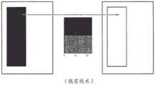
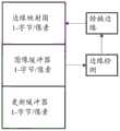
本发明的第三方面涉及多个驱动方案的使用。在某些情况下,可能期望对于单个显示器利用多个驱动方案。例如,能够显示多于两种灰度的显示器可以利用可以实现所有可能灰度之间的转变的灰度驱动方案 (“GSDS”),以及实现仅两个灰度之间的转变的单色驱动方案(“MDS”), MDS提供比GSDS更快的显示器的重写。当在显示器的重写期间正在改变的所有像素实现仅在由MDS使用的两个灰度之间的转变时使用MDS。例如,前述美国专利No.7,119,772描述了电子书或类似装置的形式的显示器,其能够显示灰度图像并且还能够显示允许用户输入与所显示图像有关的文本的单色对话框。当用户输入文本时,快速MDS被用于对话框的快速更新,由此向用户提供正在被输入的文本的快速确认。另一方面,当在显示器上显示的整个灰度图像改变时,使用较慢的GSDS。A third aspect of the invention involves the use of multiple drive schemes. In some cases, it may be desirable to utilize multiple drive schemes for a single display. For example, a display capable of displaying more than two grayscales may utilize a grayscale drive scheme ("GSDS") that enables transitions between all possible grayscales, as well as monochrome drive that enables transitions between only two grayscales Scheme ("MDS"), MDS provides faster rewriting of displays than GSDS. The MDS is used when all the pixels that are changing during the rewrite of the display implement only transitions between the two grayscales used by the MDS. For example, the aforementioned US Patent No. 7,119,772 describes a display in the form of an electronic book or similar device capable of displaying a grayscale image and also capable of displaying a monochrome dialog box that allows the user to enter text related to the displayed image. As the user enters text, the quick MDS is used for quick updates of the dialog, thereby providing the user with quick confirmation of the text being entered. On the other hand, the slower GSDS is used when the entire grayscale image displayed on the display changes.
可替换地,显示器可以同时利用GSDS和“直接更新”驱动方案 (“DUDS”)。DUDS可以具有两个或更多个灰度,通常少于GSDS,但 DUDS的最重要的特性是由简单的单向驱动处理从初始灰度至最终灰度的转变,与GSDS中通常使用的“间接”转变形成对比,在GSDS中的至少一些转变中,像素从初始灰度被驱动至一个极端光学状态,之后在相反方向上驱动至最终灰度;在一些情况下,转变可能通过从初始灰度驱动至一个极端光学状态,之后至相对的极端光学状态,并且直到那时才至最终极端光学状态来实现——参见例如,前述美国专利No.7,012,600的图11A 和11B中所示的驱动方案。由此,目前的电泳显示器可能具有大约为饱和脉冲的长度的二至三倍的灰度模式下的更新时间(其中,“饱和脉冲的长度”被定义为特定电压下的时间周期,其足以将显示器的像素从一个极端光学状态驱动至另一极端光学状态),或大约700-900毫秒,而DUDS具有等于饱和脉冲的长度的最大更新时间或大约200-300毫秒。Alternatively, the display may utilize both GSDS and a "direct update" driving scheme ("DUDS"). DUDS can have two or more grayscales, usually less than GSDS, but the most important property of DUDS is that the transition from initial grayscale to final grayscale is handled by a simple one-way drive, similar to the one commonly used in GSDS" In contrast, in at least some transitions in GSDS, a pixel is driven from an initial grayscale to an extreme optical state and then driven in the opposite direction to a final grayscale; degree driving to one extreme optical state, then to the opposite extreme optical state, and only then to the final extreme optical state is achieved - see, eg, the drive scheme shown in FIGS. 11A and 11B of aforementioned US Pat. No. 7,012,600 . Thus, current electrophoretic displays may have an update time in grayscale mode that is approximately two to three times the length of the saturation pulse (where the "length of the saturation pulse" is defined as the time period at a particular voltage that is sufficient to convert the The pixels of the display are driven from one extreme optical state to the other), or about 700-900 milliseconds, while DUDS has a maximum update time equal to the length of the saturation pulse, or about 200-300 milliseconds.
然而,驱动方案的变化不限于所使用的灰度的数量的差异。例如,驱动方案可以分成全局驱动方案和部分更新(或局部)驱动方案,在全局驱动方案中,将驱动电压施加至施加全局更新驱动方案(更准确地称为“全局完成”或“GC”驱动方案)的区域(其可以是整个显示器或其某些限定部分)中的每个像素,在部分更新驱动方案中,仅将驱动电压施加至经历非零转变(即,初始和最终灰度相互不同的转变)的像素,但在零转变(其中,初始和最终灰度相同)期间不施加驱动电压。中间形式的驱动方案(称为“全局有限”或“GL”驱动方案)类似于GC驱动方案,除了不将驱动电压施加至正经历白色至白色的零转变的像素以外。在例如用作在白色背景上显示黑色文本的电子书阅读器的显示器中,存在许多白色像素,特别是在页边空白以及文本的行之间,其从文本的一页至下一页保持不变;因此,不重写这些白色像素显著地降低了显示器重写的明显“闪烁”。然而,在这种类型的GL驱动方案中还有一些问题。首先,如在前述MEDEOD 申请中的一些中详细讨论的,双稳态电光介质通常不是完全双稳态的,处于一个极端光学状态的像素在数分钟至数小时的周期中逐渐向中间灰度漂移。特别地,被驱动为白色的像素缓慢地向浅灰色漂移。因此,如果在局部驱动方案中允许白色像素在许多翻页期间保持未驱动,而在此期间其他白色像素(例如,形成文本字符的部分的那些白色像素)被驱动,则新近更新的白色像素将比未驱动的白色像素稍微更亮,并且最终该差异甚至对未经训练的用户来说变得明显。However, the variation of the driving scheme is not limited to the difference in the number of grayscales used. For example, driving schemes can be divided into global driving schemes and partial update (or local) driving schemes in which driving voltages are applied to apply a global update driving scheme (more accurately referred to as "global complete" or "GC" driving scheme), which may be the entire display or some defined portion thereof, in a partial update driving scheme, the driving voltage is only applied to the region that undergoes a non-zero transition (i.e., the initial and final grayscales differ from each other) transitions), but no drive voltage is applied during zero transitions (where the initial and final grayscales are the same). An intermediate form of the driving scheme (referred to as the "global finite" or "GL" driving scheme) is similar to the GC driving scheme, except that no driving voltage is applied to pixels undergoing a zero white-to-white transition. In displays such as those used as e-book readers that display black text on a white background, there are many white pixels, especially in the margins and between lines of text, which remain unchanged from one page of text to the next. changes; therefore, not overwriting these white pixels significantly reduces the apparent "flicker" of display overwriting. However, there are still some problems in this type of GL driver scheme. First, as discussed in detail in some of the aforementioned MEDEOD applications, bistable electro-optic media are generally not fully bistable, with pixels in one extreme optical state gradually drifting towards mid-grey levels over periods of minutes to hours . In particular, pixels driven to white slowly drift towards light gray. Thus, if in a local drive scheme white pixels are allowed to remain undriven during many page turns, while other white pixels (eg, those that form part of text characters) are driven during this time, the newly updated white pixels will Slightly brighter than undriven white pixels, and eventually the difference becomes noticeable even to untrained users.
第二,当未驱动像素位于被更新的像素附近时,一种称为“模糊”的现象发生,其中,被驱动像素的驱动导致在稍微大于被驱动像素的区域上的光学状态的改变,这是因为位于两个像素之间的电光介质历经施加至两个像素的电压中间的电压。另外,一些电光介质,特别是电泳介质,对所施加电压不对称地反应,使得如果一个像素被一个极性的脉冲驱动并且之后被相反极性的脉冲驱动,同时相邻像素自始至终未被驱动,在这两个像素之间留下可见边缘。这种模糊将自身显示为沿着未驱动像素与被驱动像素相邻接处的边缘的边缘效应。类似的边缘效应在使用区域更新(其中仅更新显示器的特定区域以例如显示图像)时发生,除了在区域更新的情况下,在被更新的区域的边界处发生边缘效应。经过一段时间,这种边缘效应变得在视觉上分散注意力并且必须被清除。到目前为止,这种边缘效应(以及在未驱动白色像素中的颜色漂移的效应)通常通过每隔一段时间使用单个GC更新来移除。不幸地,这种临时的GC更新的使用再次引入了“闪烁”更新的问题,并且实际上,由于闪烁更新仅以长的时间间隔发生的事实,可能使得该更新的闪烁加强。Second, when an undriven pixel is located near an updated pixel, a phenomenon called "blurring" occurs, wherein the driving of the driven pixel results in a change in optical state over an area slightly larger than the driven pixel, which This is because the electro-optic medium between the two pixels experiences a voltage intermediate to the voltages applied to the two pixels. Additionally, some electro-optic media, especially electrophoretic media, respond asymmetrically to the applied voltage, such that if one pixel is driven by a pulse of one polarity and then by a pulse of the opposite polarity, while an adjacent pixel is not driven throughout, Leave a visible edge between these two pixels. This blurring will manifest itself as an edge effect along the edge where the undriven pixel adjoins the driven pixel. Similar edge effects occur when using area updates (where only certain areas of the display are updated to eg display an image), except in the case of area updates, edge effects occur at the boundaries of the areas being updated. After a while, this edge effect becomes visually distracting and must be removed. So far, this fringing effect (and the effect of color drift in undriven white pixels) has typically been removed by using a single GC update every once in a while. Unfortunately, the use of such temporary GC updates reintroduces the problem of "flashing" updates, and in fact may intensify the flickering of that update due to the fact that flashing updates only occur at long intervals.
本发明的第三方面涉及减少或消除上述问题,而同时尽可能地避免闪烁更新。然而,在试图解决前述问题时存在另外的并发问题,即需要整体 DC平衡。如在前述MEDEOD申请中的许多中论述的,如果所使用的驱动方案不是大致DC平衡的(即,如果以相同灰度开始和结束的任何系列的转变期间施加至像素的脉冲的代数和不接近于零),则显示器的电光性质和工作寿命可能被不利地影响。特别地参见前述美国专利No.7,453,445,其论述了涉及使用多于一个驱动方案执行的转变的所谓的“异构循环”中 DC平衡的问题。DC平衡驱动方案确保在任意给定时刻的总的净脉冲偏差被限制(对于有限数量的灰色状态)。在DC平衡驱动方案中,显示器的各个光学状态被分配一个脉冲电位(IP)并且光学状态之间的各个转变被限定,从而使转变的净脉冲等于转变的初始状态和最终状态之间的脉冲电位的差。在DC平衡驱动方案中,任意往返净脉冲需要大致为零。A third aspect of the present invention relates to reducing or eliminating the above-mentioned problems while avoiding flickering updates as much as possible. However, there is an additional concurrency problem in trying to solve the aforementioned problem, namely the need for overall DC balancing. As discussed in many of the aforementioned MEDEOD applications, if the driving scheme used is not approximately DC balanced (ie, if the algebraic sum of the pulses applied to the pixels during any series of transitions starting and ending at the same grayscale is not close to below zero), the electro-optic properties and operating life of the display may be adversely affected. See in particular the aforementioned U.S. Patent No. 7,453,445, which discusses the problem of DC balance in so-called "heterogeneous cycles" involving transitions performed using more than one drive scheme. The DC balanced drive scheme ensures that the total net pulse deviation at any given moment is limited (for a limited number of grey states). In a DC balanced drive scheme, each optical state of the display is assigned a pulse potential (IP) and each transition between optical states is defined such that the net pulse of the transition is equal to the pulse potential between the initial and final states of the transition poor. In a DC balanced drive scheme, any round-trip net pulse needs to be approximately zero.
因此,本发明的第三方面试图提供用于驱动电光显示器以减少前述可见边缘效应的方法。Accordingly, a third aspect of the present invention seeks to provide a method for driving an electro-optical display to reduce the aforementioned visible edge effects.
发明内容SUMMARY OF THE INVENTION
根据本发明的第一方面,现在已经发现由需要预渲染多个图像所导致的前述问题可以通过使用处于两个连续阶段中的波形来减少(如果没有被消除的话),即,仅取决于在相关转变之前的初始光学状态(或者可能地初始光学状态和在初始光学状态之前的至少一个光学状态)的第一阶段,以及取决于相关转变的初始光学状态和最终光学状态的第二阶段。According to a first aspect of the present invention, it has now been found that the aforementioned problems caused by the need to pre-render multiple images can be reduced (if not eliminated) by using waveforms in two consecutive stages, ie depending only on the A first stage of the initial optical state (or possibly the initial optical state and at least one optical state preceding the initial optical state) before the relevant transition, and a second stage of the initial and final optical state depending on the relevant transition.
因此,本发明的第一方面提供驱动包括多个像素的电光显示器的方法。该方法包括:存储表示显示器的至少一个像素的初始状态的数据;接收表示至少一个像素的最终状态的数据;以及向至少一个像素施加被配置为将至少一个像素的光学状态从初始状态改变为最终状态的波形。在本发明的方法中,所述或每个波形为两个部分,第一部分取决于像素的初始状态但不取决于其最终状态,第二部分取决于像素的初始和最终状态。Accordingly, a first aspect of the present invention provides a method of driving an electro-optical display comprising a plurality of pixels. The method includes: storing data representing an initial state of at least one pixel of the display; receiving data representing a final state of the at least one pixel; and applying to the at least one pixel configured to change the optical state of the at least one pixel from the initial state to the final state state waveform. In the method of the invention, the or each waveform is of two parts, the first part depends on the initial state of the pixel but not its final state, and the second part depends on the initial and final state of the pixel.
本发明的该方法被设计为,在最终图像被选择的时间之后,允许最终图像的预渲染,以使得仅一个最终图像需要被预渲染,并由此避免现有技术的驱动方案的问题,该现有技术的驱动方案可能涉及多个图像的预渲染,其中的一些可能从不施加至显示器。通过使用本发明的方法,当主控制器确定需要更新显示器时(例如由于用户选择了菜单上的项目),主控制器将消息发送至显示器控制器以开始更新。显示器控制器之后可以立即开始要施加至每个像素的波形的第一部分,由于该第一部分仅取决于显示器控制器已经所有的数据,主要是每个像素的现有状态,以及优选地关于每个像素的先前状态的数据,使得每个波形的该第一部分可以在显示器控制器不需要知道最终图像的细节的情况下进行。在显示器控制器执行每个波形的第一部分时,主控制器渲染最终图像,并使得该最终图像可用于显示器控制器,以使得每个波形的第一部分一旦结束,每个波形的第二部分可以立即开始。在大多数情况下,由每个波形的第一部分提供的周期将足以用于主控制器渲染最终图像,这当然取决于要呈现的图像的类型以及主控制器的数据处理能力。如果需要另外的时间,可以在显示器控制器开始每个波形的第一部分之前提供短的延迟;这种短的延迟不会实质上影响用户对显示器的响应的感知。The method of the invention is designed to allow pre-rendering of the final image after the time the final image is selected, so that only one final image needs to be pre-rendered, and thus avoid the problems of prior art driving schemes, which Prior art driving schemes may involve pre-rendering of multiple images, some of which may never be applied to the display. Using the method of the present invention, when the master controller determines that the display needs to be updated (eg, due to user selection of an item on a menu), the master controller sends a message to the display controller to initiate the update. The display controller can then immediately begin the first part of the waveform to be applied to each pixel, since this first part depends only on the data the display controller has already had, mainly the existing state of each pixel, and preferably on each pixel. Data on the previous state of the pixel, so that this first part of each waveform can be performed without the display controller needing to know the details of the final image. As the display controller executes the first part of each waveform, the master controller renders the final image and makes the final image available to the display controller so that once the first part of each waveform is over, the second part of each waveform can start immediately. In most cases, the cycles provided by the first part of each waveform will be sufficient for the main controller to render the final image, which of course depends on the type of image to be rendered and the data processing capabilities of the main controller. If additional time is required, a short delay can be provided before the display controller begins the first portion of each waveform; such a short delay does not substantially affect the user's perception of the display's response.
本发明的第一方面还提供适于执行本发明的方法的显示器控制器。The first aspect of the present invention also provides a display controller adapted to perform the method of the present invention.
本发明的第二方面提供一种驱动具有多个像素的电光显示器的方法。该方法包括(在第一测试阶段)将至少一个标准波形施加至每个像素,在施加标准波形之后测量每个像素的光学状态,针对每个像素确定要施加至像素的标准驱动方案的选择之一,以及针对每个像素存储指示所选择的标准驱动方案的至少一个选择数据。该方法还包括第二(驱动)阶段,包括:A second aspect of the present invention provides a method of driving an electro-optical display having a plurality of pixels. The method includes (in a first test stage) applying at least one standard waveform to each pixel, measuring the optical state of each pixel after applying the standard waveform, determining for each pixel a choice of standard driving schemes to be applied to the pixel One, and at least one selection data indicating the selected standard driving scheme is stored for each pixel. The method also includes a second (driving) stage comprising:
存储表示显示器的每个像素的至少初始状态的数据,以及标准驱动方案;storing data representing at least an initial state of each pixel of the display, and a standard driving scheme;
接收表示显示器的多个像素的最终灰度的输入信号;receiving an input signal representing a final grayscale of a plurality of pixels of the display;
根据表示初始状态的存储的数据、输入信号、针对相关像素以及标准驱动方案的选择数据,来确定将所述多个像素驱动至最终灰度所需的脉冲;以及determining the pulses required to drive the plurality of pixels to the final grayscale from the stored data representing the initial state, the input signal, the selection data for the relevant pixel, and the standard driving scheme; and
生成表示要施加至所述多个像素的像素电压的多个输出信号。A plurality of output signals representing pixel voltages to be applied to the plurality of pixels are generated.
为了方便,本发明的该驱动方法可以在下文中称为本发明的“像素特定驱动方法”或“PSD”方法。For convenience, this driving method of the present invention may be hereinafter referred to as the "pixel specific driving method" or "PSD" method of the present invention.
本发明还提供适于执行本发明的PSD方法的显示器控制器。这种控制器拥有规则,其用于针对显示器的每个像素存储指示要将标准驱动方案的选择中的哪一个施加至每个特定像素的至少一个选择数据,并用于考虑该选择数据来确定在显示器的更新期间要施加至每个像素的波形。The present invention also provides a display controller adapted to perform the PSD method of the present invention. Such a controller possesses rules for storing, for each pixel of the display, at least one selection data indicating which of the selections of standard driving schemes to apply to each particular pixel, and for taking this selection data into account to determine the The waveform to be applied to each pixel during an update of the display.
在本发明的PSD方法中,测试阶段可以包括将显示器的每个像素驱动至像素可以显示的每一个灰度(或者至少是将要使用的驱动方案可以显示的每一个灰度,例如16灰度中的每一个)。这便利地通过在显示器保持在固定位置时驱动显示器以显示每个灰度的一系列固态图像来完成。照相机被配置为拍摄显示器,在照相机图像的像素和显示器像素之间实现映射。在与显示器像素相对应的位置采集固态显示器图像中的每一个的照相机图像。In the PSD method of the present invention, the test phase may include driving each pixel of the display to every grayscale that the pixel can display (or at least every grayscale that the driving scheme to be used can display, such as 16 grayscales) of each). This is conveniently accomplished by driving the display to display a series of solid state images of each grey scale while the display is held in a fixed position. The camera is configured to photograph the display, enabling mapping between pixels of the camera image and pixels of the display. Camera images of each of the solid state display images are acquired at locations corresponding to display pixels.
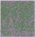
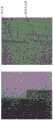
如已经论述的,颗粒和斑点是有时显示在电泳显示器模块上的伪影。针对诸如均匀灰色调的某些显示材料,伪影的低空间频率和振幅可以使得其为视觉上干扰的。本发明的PSD方法试图通过适应图像内容,或在显示过程期间以其他方式提供空间校正以校正噪声的局部色调偏移来减少显示材料的颗粒性,所述校正根据在每个可寻址空间位置(即像素)处灰度的颗粒偏移的映射图来产生。由此,PSD方法是“有源噪声消除”的形式。As already discussed, particles and speckles are artifacts sometimes displayed on electrophoretic display modules. For certain display materials, such as uniform gray tones, the low spatial frequency and amplitude of the artifacts can make them visually disturbing. The PSD method of the present invention seeks to reduce the graininess of display materials by adapting to the image content, or otherwise providing spatial corrections during the display process to correct for local hue shifts of noise, the corrections being based on at each addressable spatial location (i.e., pixels) at the grayscale of the particle offset map generated. Thus, the PSD method is a form of "active noise cancellation".
在该方法的最简单形式中,不调整可用于更新每个像素的驱动方案,而是仅改变从可用驱动信号中的选择。例如,如果在给定像素,颗粒特性使得像素过暗,则在较浅的灰色调信号所产生的灰色调被预测为与期望的更接近时,可以施加较浅的灰色调信号。通过使用空间颗粒偏移信息,获得映射以提供在每个像素处的每个灰度输入的校正。如果色调的数量小,则该映射可以预先确定并合理地存储。In the simplest form of the method, the drive scheme available to update each pixel is not adjusted, but only the selection from the available drive signals is changed. For example, if at a given pixel, grain characteristics make the pixel too dark, a lighter gray tone signal may be applied when the gray tone produced by the lighter gray tone signal is predicted to be closer to what is desired. By using the spatial grain offset information, a map is obtained to provide corrections for each grayscale input at each pixel. If the number of hues is small, the mapping can be predetermined and stored reasonably.
名义上,在PSD方法中,驱动方案被选择以使得每个灰度的颗粒图案的平均亮度在目标灰度的一定容差内。实际上,在给定面板上实现的实际平均亮度可以从面板到面板变化灰度之间间隔的大部分。经验上,已经发现在颗粒图案中发现的亮区域为大致正态地分布,其标准差取决于平均色调(以大致平滑的方式)和所施加的驱动方案。颗粒图案在对于人类视觉系统来说重要的长度标度上在空间上关联。Nominally, in the PSD method, the drive scheme is chosen such that the average brightness of the particle pattern for each grayscale is within a certain tolerance of the target grayscale. In practice, the actual average brightness achieved on a given panel can vary from panel to panel for most of the interval between grayscales. Empirically, it has been found that the bright areas found in grain patterns are approximately normally distributed, with a standard deviation that depends on the average hue (in a roughly smooth manner) and the applied drive scheme. The particle patterns are spatially associated on a length scale that is important to the human visual system.
给定这些发现,可以看出,所述的用于局部颗粒补偿的简单PSD方案将导致从目标灰度实现的平均灰度的布局中误差的减小。此外,已经发现,由于与相邻灰度之间的间隔相比,颗粒方差变大,所产生的校正灰色调的方差接近具有(1/12)0.5或大致0.3度的标准差的均匀分布的方差。参见图1,其示出针对标称灰度布局从目标水平的两种不同偏移在基线颗粒消除中的PSD方法的模拟性能。在两种情况中,灰度布局误差在大的本地颗粒标准差时收敛至零,并且所得到的标准差在[-0.5,0.5]度收敛至均匀分布。Given these findings, it can be seen that the described simple PSD scheme for local grain compensation will result in a reduction in error in the layout of the average grayscale achieved from the target grayscale. Furthermore, it has been found that since the variance of the particles becomes larger compared to the spacing between adjacent gray levels, the variance of the resulting corrected gray tones approaches a uniform distribution with a standard deviation of (1/12)0.5 or roughly 0.3 degrees variance. See Figure 1, which shows the simulated performance of the PSD method in baseline particle removal for two different shifts of the nominal grayscale layout from the target level. In both cases, the grayscale layout error converges to zero at large local grain standard deviations, and the resulting standard deviations converge to a uniform distribution at [-0.5, 0.5] degrees.
该方差的减小是PSD方法的主要目标,因为其降低了颗粒的可见性。然而,甚至在所产生的降低水平,由于颗粒图案中的空间关联,所得到的纹理图案可能为视觉上干扰的;当通过在每个像素处选择最接近的可用灰度来渲染灰度时,大范围的类似选择的灰度可以产生,并且因为人眼对结果空间频率敏感,所以伪影保持容易地可见。因此,需要用于在显示器的每个像素处的可用灰度中进行选择的改进方法,其保留接近目标值的平均亮度并降低校正后的颗粒图案的可见性,这种改进的方法由本发明的第二方面的第二方法提供,其中,抖动或图像半色调技术用于将颗粒置于较高空间频率以使得其更少地可见,同时维持对均匀值的严格约束以保持接近灰度布局目标。在大多数情况下,这在最佳情况中导致总噪声方差的增大,但仍提供噪声可见度的减小。The reduction of this variance is the main goal of the PSD method because it reduces the visibility of particles. However, even at the resulting reduced level, the resulting texture pattern can be visually disturbing due to the spatial associations in the grain pattern; when the grayscale is rendered by selecting the closest available grayscale at each pixel, A wide range of similarly chosen grayscales can be produced, and because the human eye is sensitive to the resulting spatial frequencies, artifacts remain easily visible. Therefore, there is a need for an improved method for selecting among the available grayscales at each pixel of a display that preserves an average brightness close to the target value and reduces the visibility of the corrected particle pattern, and such an improved method is provided by the present invention The second method of the second aspect provides wherein dithering or image halftoning techniques are used to place particles at higher spatial frequencies so that they are less visible, while maintaining strict constraints on uniform values to remain close to grayscale layout goals . In most cases, this results in an increase in the total noise variance in the best case, but still provides a reduction in noise visibility.
本发明的第三方面提供驱动具有多个像素的电光显示器的方法。该方法使用针对从初始灰度至最终灰度的每个转变来定义要施加至每个像素的波形的驱动方案。针对驱动方案中的至少一个转变,在驱动方案中提供多个波形,所述多个波形被随机施加至经历相关转变的像素,以使得经历相同转变的不同像素体验不同的波形。A third aspect of the present invention provides a method of driving an electro-optical display having a plurality of pixels. The method uses a drive scheme that defines the waveform to be applied to each pixel for each transition from an initial grayscale to a final grayscale. For at least one transition in the drive scheme, a plurality of waveforms are provided in the drive scheme that are randomly applied to pixels undergoing the relevant transition such that different pixels undergoing the same transition experience different waveforms.
可以理解,本发明的该方法需要显示器控制器,其可以在逐个像素基础上施加不同的波形,如这里所述。It will be appreciated that this method of the present invention requires a display controller that can apply different waveforms on a pixel-by-pixel basis, as described herein.
可以理解,在本发明的该方法中用于特定转变的多个波形将不必须都具有相同的净脉冲,并且为了产生趋于最小化边缘效应和类似视觉问题的随机效应,在本方法中合理的是每隔一段时间改变哪个波形用于在特定像素处的哪个转变。因此,除非采取预防,该方法可能导致DC不平衡的积累。在许多情况下,多个波形的净脉冲之间的差异很小,并且根据所使用的电光显示器的类型,可以在不显著地损坏显示器的情况下被容许。可替换地,在每个像素处的DC不平衡可以被追踪(如在前述MEDEOD申请中所述),针对特定转变的特定波形的选择被偏置,以意于减少特定像素处的累积DC不平衡。在本方法的另一实施例中,针对驱动方案中的转变的每一个提供多个波形,并且任一个像素针对每个转变使用第一、第二、第三等波形。实际上,针对每个转变的第一、第二、第三等波形的集合形成不同的驱动方案,在任一次这些驱动方案中的仅一个被施加至特定像素。(这些驱动方案中的每一个是相同的类型或“模式”,即,驱动方案中的每一个可以是全局完成驱动方案或全局有限驱动方案,但全部必须是相同类型。由此,本发明的该实施例不同于序列号为13/755,111的前述共同未决的申请中所描述的选择性一般更新驱动方案,其中,第一驱动方案在第一更新期间被施加至显示器的像素的非零次要部分,而第二驱动方案在第一更新期间被施加至剩余像素,而在第一更新之后的第二更新期间,第一驱动方案被施加至像素的不同的非零次要部分,而第二驱动方案在第二更新期间被施加至剩余像素;在选择性一般更新驱动方案中,两个驱动方案是不同类型。)期望地,在本发明的该实施例中使用的不同驱动方案中的每一个是自身DC平衡的,并且期望地,不同驱动方案的两个之间的像素的切换仅在像素达到特定光学状态时实现,以使得驱动方案之间的切换不会导致DC不平衡的积累。通常,特定光学状态将包括像素的极端光学状态之一。It will be appreciated that the multiple waveforms used for a particular transition in this method of the present invention will not necessarily all have the same net pulse, and in order to generate random effects that tend to minimize edge effects and similar vision problems, it is reasonable in this method The point is to change which waveform is used for which transition at a particular pixel at intervals. Therefore, unless preventive measures are taken, this approach may lead to the accumulation of DC imbalances. In many cases, the differences between the net pulses of the multiple waveforms are small and, depending on the type of electro-optic display used, can be tolerated without significantly damaging the display. Alternatively, the DC imbalance at each pixel can be tracked (as described in the aforementioned MEDEOD application), and the selection of specific waveforms for specific transitions biased to reduce the cumulative DC imbalance at specific pixels. balance. In another embodiment of the method, multiple waveforms are provided for each of the transitions in the drive scheme, and any one pixel uses a first, second, third, etc. waveform for each transition. In effect, the set of first, second, third, etc. waveforms for each transition forms a different drive scheme, with only one of these drive schemes being applied to a particular pixel at any one time. (Each of these drive schemes is of the same type or "mode", i.e., each of the drive schemes can be either a global complete drive scheme or a global finite drive scheme, but all must be of the same type. Thus, the This embodiment differs from the selective general update drive scheme described in the aforementioned co-pending application Ser. No. 13/755,111, wherein the first drive scheme is applied to the pixels of the display non-zero times during the first update while the second drive scheme is applied to the remaining pixels during the first update, and during the second update following the first update, the first drive scheme is applied to a different non-zero minor portion of the pixel, and the first Two drive schemes are applied to the remaining pixels during the second update; in the selective general update drive scheme, the two drive schemes are of different types.) Desirably, among the different drive schemes used in this embodiment of the invention Each is DC balanced by itself, and desirably, switching of pixels between two of the different drive schemes is only achieved when the pixels reach a certain optical state, so that switching between drive schemes does not result in the accumulation of DC imbalances . Typically, the particular optical state will include one of the extreme optical states of the pixel.
本发明的第三方面还提供驱动具有多个像素的电光显示器的另一方法。该方法包括施加局部驱动方案以改变显示器的至少一个有限区域的光学状态。至少一个有限区域的光学状态的改变伴随着驱动边缘消除区域中的像素,边缘消除区域为至少一个像素宽并且基本上围绕所述至少一个有限区域。边缘消除区域中的像素首先从它们的初始灰度被驱动至中间灰度,之后被驱动回至其初始灰度(注意,由于边缘消除区域中的像素在施加局部更新的至少一个有限区域外部,因而边缘消除区域中的像素的最终灰度将与其初始灰度相同)。A third aspect of the present invention also provides another method of driving an electro-optic display having a plurality of pixels. The method includes applying a local drive scheme to change the optical state of at least one limited area of the display. The change in the optical state of the at least one finite area is accompanied by driving the pixels in the edge-eliminated area, the edge-eliminated area being at least one pixel wide and substantially surrounding the at least one finite area. Pixels in the edge-eliminated region are first driven from their initial grayscale to intermediate grayscales and then driven back to their original grayscale (note that since pixels in the edge-eliminated region are outside at least one finite region where local updates are applied, Thus the final grayscale of the pixels in the edge-eliminated area will be the same as its initial grayscale).
在说到边缘消除区域“基本上围绕”局部驱动方案被施加至的至少一个有限区域时,我们的意思是说边缘消除区域至少包括与至少一个有限区域共享公共边缘的像素。不是必要的但通常期望的是,边缘消除区域包括仅与至少一个有限区域共享公共角的像素。When it is said that the edge removal area "substantially surrounds" the at least one finite area to which the local driving scheme is applied, we mean that the edge removal area includes at least pixels that share a common edge with the at least one finite area. It is not necessary, but generally desirable, that the edge removal area includes pixels that only share a common angle with at least one limited area.
在该“边缘消除”方法中,边缘消除区域可以大于一个像素宽,并且不是必须将边缘消除区域中的所有像素驱动至相同的中间灰度;可以通过将像素的各个集合、以及特别地与至少一个有限区域的边界的距离不同的像素的各个集合驱动至不同的中间灰度来更有效地实现边缘消除。此外,本发明的方法不限于将边缘消除区域中的像素驱动至单一中间灰度;这种边缘消除像素可以被驱动至一系列中间灰度,并且多个中间灰度的使用可以有益于最小化边缘效应。In this "edge removal" method, the edge removal area can be larger than one pixel wide, and it is not necessary to drive all pixels in the edge removal area to the same intermediate grayscale; Each set of pixels at different distances from the boundary of a limited area are driven to different intermediate grayscales to achieve edge removal more efficiently. Furthermore, the method of the present invention is not limited to driving pixels in edge-eliminated regions to a single intermediate grayscale; such edge-eliminated pixels can be driven to a range of intermediate grayscales, and the use of multiple intermediate grayscales can be beneficial to minimize edge effect.
施加至边缘消除区域的波形可以与由局部驱动方案施加的波形相同,或者可以在边缘消除区域中使用特定的“边缘消除”驱动方案。在边缘消除区域中使用的确切中间灰度通常不是很重要,因为边缘消除区域通常很窄,并且边缘消除区域中的改变的视觉效果通常在至少一个有限区域中发生的更大改变中丢失;主要的考虑是确保在转变之后的至少一个有限区域的边界周围不留下可见边缘。在其他情况下,在边缘消除区域中所使用的波形的细节可能不那么重要,并且其可以是通过边缘消除区域中使用的极为重要的波形所实现的转变。还可以发现,在许多情况下,用于局部更新的仅一部分波形负责边缘效应的形成,用于边缘消除区域的波形与用于局部更新的波形的定时可以对现在的边缘缺陷的可见度具有重要的影响。The waveform applied to the edge removal area may be the same as the waveform applied by the local drive scheme, or a specific "edge removal" driving scheme may be used in the edge removal area. The exact intermediate grayscale used in the edge-elimination area is generally not important because the edge-elimination area is usually narrow, and the visual effect of changes in the edge-elimination area is usually lost in larger changes that occur in at least one limited area; mainly The consideration is to ensure that no visible edges are left around the boundary of at least one limited area after the transition. In other cases, the details of the waveform used in the edge removal area may be less important, and it may be a transition achieved by the very important waveform used in the edge removal area. It has also been found that in many cases only a portion of the waveform used for the local update is responsible for the formation of edge effects, and the timing of the waveform used for the edge removal area and the waveform used for the local update can be important for the visibility of edge defects now. influences.
上述考虑表明,在该边缘消除方法中,通常优选的是,在边缘消除区域中所使用的驱动方案是特定边缘消除驱动方案,只要所使用的显示器控制器可以适应该另外的驱动方案。这种特定边缘消除驱动方案可以被调整以给出关于利用特定灰度组合的边缘消除的最佳结果。如上所述,边缘效应通常仅在整个转变完成之后是重要的,因为在转变期间的短暂边缘效应通常被显示器的用户忽略。此外,当显示器的有限区域转变至与另一灰度对照的一个灰度时,边缘效应更引人注意,从这个意义上,边缘效应通常是不对称的。特别地,当显示器具有形成所显示图像的背景的处于相同灰度的大量像素(例如,形成一系列黑色文本或黑线的背景的在白色背景图像上的大量白色像素)并且这些背景像素中的许多仅很少地被更新时,边缘效应可能在显示器的有限区域转变至背景颜色时最严重。The above considerations show that in this edge removal method, it is generally preferred that the driving scheme used in the edge removal area is a specific edge removal driving scheme, so long as the display controller used can accommodate the additional driving scheme. This specific edge removal drive scheme can be adjusted to give optimal results with respect to edge removal with specific grayscale combinations. As mentioned above, edge effects are generally only significant after the entire transition is complete, since brief edge effects during transitions are often ignored by the user of the display. Furthermore, edge effects are more noticeable when a limited area of the display transitions to one grayscale as opposed to another, in the sense that edge effects are often asymmetrical. In particular, when a display has a large number of pixels at the same grayscale that form the background of a displayed image (eg, a large number of white pixels on a white background image that form the background of a series of black text or black lines) and those background pixels While many are updated only infrequently, edge effects can be most severe when a limited area of the display transitions to the background color.
边缘消除方法可以与单色和灰度局部驱动方案一起使用。Edge removal methods can be used with monochrome and grayscale local drive schemes.
本发明还提供适于执行本发明的边缘消除方法的显示器控制器。本发明的显示器控制器能够驱动具有多个像素的电光显示器,并且包括用于检测经历转变的显示器的有限区域的边缘、并用于确定至少一个像素宽并基本围绕至少一个有限区域的边缘消除区域的边缘检测部件,以及用于将边缘消除区域中的像素从其初始灰度驱动至中间灰度并之后驱动回至其初始灰度的部件。The present invention also provides a display controller adapted to perform the edge removal method of the present invention. The display controller of the present invention is capable of driving an electro-optical display having a plurality of pixels and includes means for detecting edges of a limited area of the display undergoing transition and for determining an edge cancellation area that is at least one pixel wide and substantially surrounds the at least one limited area. Edge detection means, and means for driving the pixels in the edge-eliminated region from their initial grayscale to an intermediate grayscale and then back to their initial grayscale.
在本发明的所有方法中,显示器可以利用上述任何类型的电光介质。由此,例如,电光显示器可以包括旋转双色元件或电致变色材料。可替换地,电光显示器可以包括包含多个带电粒子的电泳材料,带电粒子布置在流体中并且能够在电场的影响下移动穿过流体。带电粒子和流体可以被限制在多个囊体或微单元内。可替换地,带电粒子和流体可以作为由包括聚合物材料的连续相围绕的多个离散微滴而存在。流体可以是液态或气态的。In all methods of the present invention, the display may utilize any of the types of electro-optic media described above. Thus, for example, an electro-optical display may comprise a rotating dichromatic element or an electrochromic material. Alternatively, the electro-optic display may comprise an electrophoretic material comprising a plurality of charged particles arranged in a fluid and capable of moving through the fluid under the influence of an electric field. Charged particles and fluids can be confined within multiple capsules or microcells. Alternatively, the charged particles and fluid may exist as a plurality of discrete droplets surrounded by a continuous phase comprising a polymeric material. Fluids can be liquid or gaseous.
附图说明Description of drawings
如已经提到的,图1是示出在基线颗粒消除中针对标称灰度布局从目标水平的两种不同偏移的、本发明的简单PSD方法的模拟性能的图。As already mentioned, Figure 1 is a graph showing the simulated performance of the simple PSD method of the present invention for two different shifts of the nominal grayscale layout from the target level in baseline grain removal.
图2是类似于图1的示意图,示出在本发明的改进控制器中的存储器布置。Figure 2 is a schematic diagram similar to Figure 1 showing the memory arrangement in the improved controller of the present invention.
图3是示出使用本发明的简单PSD方法在电泳显示器中所实现的颗粒的改善的图。Figure 3 is a graph showing the improvement of particles achieved in an electrophoretic display using the simple PSD method of the present invention.
图4-6示出根据本发明的对噪声减少应用抖动和图像半色调技术的模拟。4-6 illustrate simulations of applying dithering and image halftone techniques to noise reduction in accordance with the present invention.
图7的附图示意性地示出使用现有技术的驱动方法的、电光显示器的有限区域从黑色至白色的转变,以及产生的边缘效应。The drawing of FIG. 7 schematically illustrates the transition from black to white of a limited area of an electro-optical display, and the resulting edge effects, using a prior art driving method.
图8A是类似于图4但示出使用根据本发明的第三方面的驱动方法的类似转变的示意图。FIG. 8A is a schematic diagram similar to FIG. 4 but showing a similar transition using the driving method according to the third aspect of the present invention.
图8B示出由本发明的第三方面的驱动方法实现的减少的边缘效应。FIG. 8B illustrates the reduced edge effect achieved by the driving method of the third aspect of the present invention.
图9是示意性示出用于双稳态电光显示器的现有技术的显示器控制器的架构的框图。Figure 9 is a block diagram schematically illustrating the architecture of a prior art display controller for a bistable electro-optic display.
图10示出图9所示的现有技术的控制器的控制器存储器结构。FIG. 10 shows a controller memory structure of the prior art controller shown in FIG. 9 .
图11示出本发明的可以用于显示器控制器中的边缘检测的简单拉普拉斯滤波器。Figure 11 shows a simple Laplacian filter of the present invention that can be used for edge detection in a display controller.
图12示出图11所示的拉普拉斯滤波器的检测显示器中的边缘像素的使用。FIG. 12 illustrates the use of the Laplacian filter shown in FIG. 11 to detect edge pixels in a display.
图13是类似于图10的本发明的显示器控制器的控制器存储器架构的示意图。FIG. 13 is a schematic diagram of the controller memory architecture of the display controller of the present invention similar to that of FIG. 10 .
图14是类似于图9但示意性示出使用图13的控制器存储器架构的本发明的显示器控制器的架构的框图。FIG. 14 is a block diagram similar to FIG. 9 but schematically showing the architecture of a display controller of the present invention using the controller memory architecture of FIG. 13 .
图15示出可以在图14的显示器控制器中使用的查找表。FIG. 15 shows a look-up table that may be used in the display controller of FIG. 14 .
具体实施方式Detailed ways
如已经描述的,本发明具有三个主要方面并提供用于改善在电光显示器上显示的图像的各种方法。尽管以下主要分别描述了本发明的各种方法,但对于电光显示器的技术的技术人员来说明显的是,在实践中,单一物理显示器可以同时地或顺序地利用本发明的多于一种方法。例如,单一显示器可以利用根据本发明的第一方面的两部分波形以减少控制器上的预渲染负担,并且还可以利用根据本发明的第三方面的边缘消除方法以消除所显示图像中的边缘效应。As already described, the present invention has three main aspects and provides various methods for improving images displayed on electro-optic displays. Although the various methods of the present invention are mainly described below separately, it will be apparent to those skilled in the art of electro-optic displays that, in practice, a single physical display may utilize more than one method of the present invention simultaneously or sequentially . For example, a single display may utilize the two-part waveform according to the first aspect of the invention to reduce the pre-rendering burden on the controller, and may also utilize the edge removal method according to the third aspect of the invention to remove edges in the displayed image effect.
部分A:两部分波形Part A: Two-Part Waveform
如上所述,本发明的第一方面提供驱动电光显示器的“两部分波形”方法。该方法包括存储表示显示器的至少一个像素的初始状态的数据;接收表示该至少一个像素的最终状态的数据;以及向该至少一个像素施加被配置为将该至少一个像素的光学状态从初始状态改变为最终状态的波形。在本发明的方法中,所述或每个波形是两部分,第一部分取决于像素的初始状态但不取决于其最终状态,第二部分取决于像素的初始和最终状态两者。As mentioned above, a first aspect of the present invention provides a "two-part waveform" method of driving an electro-optical display. The method includes storing data representing an initial state of at least one pixel of a display; receiving data representing a final state of the at least one pixel; and applying to the at least one pixel configured to change the optical state of the at least one pixel from the initial state is the final state waveform. In the method of the present invention, the or each waveform is two parts, the first part depends on the initial state of the pixel but not its final state, and the second part depends on both the initial and final state of the pixel.
可以以与现有技术波形(如在前述MEDEOD申请中所述)类似的方式创建适于在该两部分波形方法中使用的波形,除了从特定初始状态开始的所有波形的第一部分必须相同以外。例如,在灰度驱动方案(即,每个像素能够显示两个极端光学状态和两个极端光学状态中间的至少一个灰度光学状态的驱动方案)中,每个波形的第一部分可以将像素驱动至中间灰度,而每个波形的第二部分将其从中间灰度驱动至最终期望灰度。整体效果将是,在波形的第一部分结束时,所有像素将处于相同的中间灰度,以使得初始图像消失在固态中间灰度图像中,最终图像将从固态中间灰度图像出现。而且,可以理解,驱动方案中所有波形的第一部分将必须是相同的长度;如果必要,一些波形可以用零电压的时期来“被填满”,以满足该限制。保持这些限制将确保每个波形可以被分解成用于本发明的方法中的第一和第二部分。如果控制器不能连续地播放两个波形并需要在之间的一些停顿,则这也必须通过将该停顿加到限制中来被考虑。假定这是可行的是合理的,这是由于调整前的基础波形可以允许第一波形阶段为波形的总长度的至少约50%、优选地约66%。即使在调整之后,许多现有技术的波形可以被修改并轻微重新调整以针对波形的前面的几个帧排列。Waveforms suitable for use in this two-part waveform method can be created in a similar manner to prior art waveforms (as described in the aforementioned MEDEOD application), except that the first part of all waveforms from a particular initial state must be the same. For example, in a grayscale driving scheme (ie, a driving scheme in which each pixel is capable of displaying two extreme optical states and at least one grayscale optical state intermediate the two extreme optical states), the first portion of each waveform may drive the pixel to mid-gray, and the second portion of each waveform drives it from mid-gray to the final desired gray-scale. The overall effect will be that by the end of the first part of the waveform, all pixels will be at the same mid-gray, so that the initial image disappears into the solid mid-gray image and the final image will emerge from the solid mid-grey image. Also, it will be appreciated that the first portion of all waveforms in the drive scheme will have to be the same length; if necessary, some waveforms may be "filled in" with periods of zero voltage to meet this limit. Maintaining these constraints will ensure that each waveform can be decomposed into first and second parts for use in the method of the present invention. If the controller cannot play two waveforms continuously and needs some pause in between, this must also be taken into account by adding that pause to the limit. It is reasonable to assume that this is possible since the base waveform before adjustment may allow the first waveform stage to be at least about 50%, preferably about 66% of the total length of the waveform. Even after adjustment, many prior art waveforms can be modified and slightly rescaled to line up for the first few frames of the waveform.
从上述描述可以看出,本发明的两部分波形方面提供驱动方法和显示器控制器,其允许在用于转变的波形已经开始之后图像的渲染,由此确保主控制器仅需要一次渲染一个图像并且降低存储器和功率需求。本方法还用于应对显示器的用户的想法的突然改变。假定例如阅读电子书的用户意外地错误地按下“前一页”按钮,并且立即通过按下“下一页”按钮来纠正他的错误。在前述MEDEOD申请中描述的许多现有技术的显示器中,转变一旦开始就不能被中断,因为终止部分完成的所施加波形将使得显示器处于未知状态,并且可能影响显示器的DC平衡。因此,在该情形中,显示器将必须在进行至实际期望的页之前完成显示器的重写以显示前一页。然而,当使用本发明的方法时,在第一次按钮按下时,主控制器将告知显示器控制器开始相关波形的第一部分并开始渲染(错误的)下一图像。在接收到第二次按钮按下时,主控制器不需要停止相关波形的第一部分的施加,因为这些第一部分对于错误的和正确的接下来的图像将是相同的。主控制器可以取消错误的下一图像的渲染并开始正确的下一图像的渲染。等到波形的第一部分施加至显示器时,或者在此不久之后,主控制器完成渲染正确的下一图像,并且显示器控制器可以继续针对正确的下一图像施加波形的适当的第二部分。整体效果是,正确的下一图像在用于显示器的单个更新的时间帧内或稍长的周期内显示,而不是如现有技术中那样花费用于显示器的两个完整更新的全部时间。As can be seen from the above description, the two-part waveform aspect of the present invention provides a drive method and a display controller that allow rendering of images after the waveform for the transition has started, thereby ensuring that the main controller only needs to render one image at a time and Reduce memory and power requirements. The method is also used to deal with sudden changes in the mind of the user of the display. Suppose, for example, that a user reading an e-book accidentally presses the "previous page" button by mistake, and immediately corrects his mistake by pressing the "next page" button. In many of the prior art displays described in the aforementioned MEDEOD application, the transition once started cannot be interrupted because terminating a partially completed applied waveform would leave the display in an unknown state and may affect the DC balance of the display. Thus, in this case, the display would have to complete a rewrite of the display to display the previous page before proceeding to the actual desired page. However, when using the method of the present invention, on the first button press, the main controller will tell the display controller to start the first part of the relevant waveform and start rendering the (erroneous) next image. Upon receipt of the second button press, the master controller need not stop the application of the first parts of the relevant waveform, as these first parts will be the same for the wrong and correct subsequent images. The master controller can cancel the rendering of the wrong next image and start the rendering of the correct next image. When, or shortly after, the first portion of the waveform is applied to the display, the master controller finishes rendering the correct next image, and the display controller can proceed to apply the appropriate second portion of the waveform for the correct next image. The overall effect is that the correct next image is displayed within the time frame or slightly longer period for a single update of the display, rather than spending the full time for two complete updates of the display as in the prior art.
两部分波形方法的方法几乎不需要修改显示器控制器,并且实际上通常仅需要波形的轻微修改。The method of the two-part waveform method requires little modification of the display controller, and in fact usually only requires slight modification of the waveform.
部分B:像素特定驱动方法Part B: Pixel-Specific Driving Methods
如上所述,本发明的第二方面的像素特定驱动(PSD)方法包括第一 (或测试)阶段,其需要将至少一个标准波形施加至每个像素,在施加标准波形之后测量每个像素的光学状态,针对每个像素确定要施加至像素的标准驱动方案的选择之一,并针对每个像素存储指示所选择的标准驱动方案的至少一个选择数据。短语“标准驱动方案的选择之一”应该被广义地解释,并且不限于选择所有细节被提前定义的有限数量的驱动方案之一。例如,如在前述美国专利No.7,012,600中所述,方法可以利用包含一个或多个变量参数(例如,波形的总长度或其子部分的长度)的一个或多个标准驱动方案,并且可以基于在测试阶段中积累的数据来选择要用于特定像素的参数。可替换地,如参考图2和3所述,可以通过针对特定转变使用存在于标准驱动方案中但在该驱动方案中意在用于不同转变的波形来实现驱动方案的选择。测试阶段的目的是积累关于显示器的各个像素的行为的数据,以使得最合适的驱动方案可以在方法的第二驱动阶段期间施加至每个像素。该驱动阶段以与前述美国专利No.7,012,600和其他MEDEOD 申请中相同的方式来执行,除了针对每个像素独立地选择所使用的驱动方案以获得每个像素处与期望灰度最接近的灰度,而不管各个像素的行为的变化。As mentioned above, the Pixel Specific Driving (PSD) method of the second aspect of the present invention includes a first (or test) stage which entails applying at least one standard waveform to each pixel, after applying the standard waveform measuring each pixel's An optical state, determining for each pixel one of the selections of standard driving schemes to be applied to the pixel, and storing for each pixel at least one selection data indicating the selected standard driving scheme. The phrase "one of the choice of standard driving schemes" should be interpreted broadly and not limited to the choice of one of a limited number of driving schemes, all details of which are defined in advance. For example, as described in the aforementioned US Patent No. 7,012,600, the method may utilize one or more standard drive schemes including one or more variable parameters (eg, the overall length of the waveform or the length of a subsection thereof), and may be based on The data accumulated during the test phase is used to select the parameters to be used for a particular pixel. Alternatively, as described with reference to Figures 2 and 3, selection of a drive scheme may be achieved by using waveforms that exist in a standard drive scheme for a particular transition but are intended for different transitions in that drive scheme. The purpose of the testing phase is to accumulate data on the behavior of the individual pixels of the display so that the most suitable driving scheme can be applied to each pixel during the second driving phase of the method. This driving stage is performed in the same manner as in the aforementioned US Pat. No. 7,012,600 and other MEDEOD applications, except that the driving scheme used is independently selected for each pixel to obtain the closest grayscale to the desired grayscale at each pixel , regardless of changes in the behavior of individual pixels.
如已经提到的,在PSD方法的一种形式中,测试阶段包括将显示器的每个像素驱动至像素可以显示的每一个灰度(或者至少是要使用的驱动方案可以显示的每一个灰度,例如16个灰度中的每一个)。这便利地通过在显示器保持在固定位置时驱动显示器以显示每个灰度的一系列固态图像来完成。照相机被配置为拍摄显示器,在照相机图像的像素和显示器像素之间实现映射。在与显示器像素相对应的位置采集固态显示器图像中的每一个的照相机图像,该图像在该像素处使用给定驱动方案可获得,并由此表示逐个像素灰度再现曲线。由于空间噪声,在特定像素处使用针对期望灰度的波形实际实现的反射率可能不是最佳的;与不同最终灰度相关联的波形可以实现与期望灰度最接近的反射率。图2示出该方式。在图2中,下面的曲线示出针对在16灰度标度上处于灰度9的各个像素测量的实际反射率,而上面的曲线示出对期望灰度作出的调整以考虑下面的曲线中示出的误差;可以看出,大部分像素被设置为使用灰度9的波形,但某些像素被设置为使用灰度8或10的波形。将该观念应用到所有像素处的所有输入灰度导致逐个像素查找表,其将输入灰度映射至给出最好结果的实际灰度指数。期望地,与输入灰度相关联的期望反射率被选择为相应固态灰度图像的反射率的平均值,以使得本发明的PSD方法产生与未修改的驱动方法相同的平均灰度色调。最后,在渲染阶段,逐个像素查找表被使用来修改施加至各个像素的电压,并替代每个像素的单独的查找表中的该像素处的相应的项目。As already mentioned, in one form of the PSD method, the test phase consists of driving each pixel of the display to every grayscale that the pixel can display (or at least every grayscale that the driving scheme to be used can display) , such as each of the 16 shades of gray). This is conveniently accomplished by driving the display to display a series of solid state images of each grey scale while the display is held in a fixed position. The camera is configured to photograph the display, enabling mapping between pixels of the camera image and pixels of the display. A camera image of each of the solid state display images is acquired at a location corresponding to a display pixel at which the image is obtainable using a given drive scheme, and thus represents a pixel-by-pixel grayscale reproduction curve. The reflectivity actually achieved using the waveform for the desired grayscale at a particular pixel may not be optimal due to spatial noise; waveforms associated with different final grayscales may achieve the reflectivity closest to the desired grayscale. Figure 2 shows this approach. In Figure 2, the lower curve shows the actual reflectance measured for each pixel at grayscale 9 on a 16-gray scale, while the upper curve shows the adjustment made to the desired grayscale to take into account that in the lower curve Error shown; it can be seen that most of the pixels are set to use the waveform in grayscale 9, but some pixels are set to use the waveform in
PSD方法已经被定性地表明为非常成功,显著减少了高颗粒面板/波形系统中的可见颗粒伪影,而不用其他补救。特别地,该方法已经被定性地示出提供在高颗粒面板中的显著的噪声减少;参见图3,其示出使用PSD 方法在电泳显示器中所实现的颗粒的减少。可以看出,尽管在极端黑色和白色灰度,颗粒轻微增加,但在中间灰度(其中,颗粒最显而易见)实现了颗粒的大量减少。PSD方法还可以用于补救某些制造缺陷,诸如条纹。通过将灰度布局和重影的部分控制从波形形成移动至稍后的再现过程中,内部面板性能可变性可以减少,由此减轻了对成批的显示器调整波形的负担。PSD方法还可以通过允许使用以其他方式显示过多噪声的显示器来提高生产产量。The PSD method has been qualitatively shown to be very successful, significantly reducing visible grain artifacts in high grain panel/waveform systems without other remedies. In particular, this method has been qualitatively shown to provide significant noise reduction in high particle panels; see Figure 3, which shows particle reduction achieved in electrophoretic displays using the PSD method. It can be seen that while at the extreme black and white grayscales there is a slight increase in grain, a large reduction in grain is achieved at mid-scale grayscales, where grain is most visible. The PSD method can also be used to remedy certain manufacturing defects, such as streaks. By moving partial control of grayscale layout and ghosting from waveform formation to later in the rendering process, internal panel performance variability can be reduced, thereby reducing the burden of adjusting waveforms on batch displays. The PSD method can also improve production yield by allowing the use of displays that otherwise display excessive noise.
部分C:抖动和/或图像半色调技术的使用Part C: Use of Dithering and/or Image Halftone Techniques
如上所述,本发明的第二方面可以可替换地应用抖动或图像半色调技术以将颗粒噪声布置在更高的空间频率中,以使得它更少地可见,同时维持对平均灰度值的严格约束以保持接近灰度布局目标。在大多数情况下,这将导致总噪声方差的增大,但仍提供噪声可见度的减小。As mentioned above, the second aspect of the present invention may alternatively apply dithering or image halftoning techniques to place grain noise in higher spatial frequencies so that it is less visible, while maintaining sensitivity to the mean grey value Strictly constrained to stay close to the grayscale layout target. In most cases, this will result in an increase in the total noise variance, but still provide a reduction in noise visibility.
抖动和图像半色调技术的技术人员将认识到本发明的第二方法中的这种技术的应用的一个不寻常的特征:不像传统的抖动应用,在第二方法中,可得到的灰度在整个图像上不是恒定的,而是空间变化的。传统的抖动算法应该被修改以通过找到合适的一般化来考虑该情况。例如,考虑分散点抖动。通常,分散点抖动的有效实施是使用多级阈值矩阵,但该技术没有很好地概括在空间上变化的灰度。代替地,可以在“筛查”意义上使用抖动,由此将筛查函数添加至抖动的信号,并且之后在每个位置寻找与结果图像最近的可用灰度;即使可用灰度在空间上变化该技术也起作用。对筛查函数的值、位置和振幅的选择将影响潜在的颗粒噪声可见的程度以及结果图像的纹理以及平均值和方差。Those skilled in dithering and image halftoning techniques will recognize an unusual feature of the application of this technique in the second method of the present invention: unlike conventional dithering applications, in the second method the available grayscale Not constant over the entire image, but spatially variable. Traditional dithering algorithms should be modified to account for this situation by finding a suitable generalization. For example, consider scattered point jitter. Often, an efficient implementation of scattered point dithering is to use a multilevel threshold matrix, but this technique does not generalize well for spatially varying grayscales. Instead, dithering can be used in the "screening" sense, whereby a screening function is added to the dithered signal, and then at each location the closest available grayscale to the resulting image is found; even if the available grayscale varies spatially This technique also works. The choice of the value, location and amplitude of the screening function will affect the degree to which potential grain noise is visible and the texture as well as the mean and variance of the resulting image.
附图中的图4-6示出本发明的这种第二方法的模拟。图4示出处于灰度8的放大的模拟颗粒图案,颗粒噪声标准差为0.5灰度。图5示出根据本发明的PSD方法的将每个像素设置为对于灰度8的目标亮度最接近的可用灰度的模拟结果。标称(平均)灰度亮度为过暗0.25度,而映射的结果具有过暗的平均值0.0012度,标准差为0.2892。然而,应该注意目前的类似选择的灰色调的相当大的范围。图6示出了当选择使用以下2×2筛查函数映射的灰度时,应用所提出的筛查方法的模拟结果:Figures 4-6 of the accompanying drawings illustrate simulations of this second method of the invention. Figure 4 shows an enlarged simulated particle pattern at
1/4*[-2 1;2 -1]1/4*[-2 1; 2 -1]
所得到的平均值是-0.00012度,标准差0.4892。尽管噪声方差比仅使用PSD方法的图5大,但噪声主要存在于较高的空间频率并且不被注意。The resulting mean is -0.00012 degrees with a standard deviation of 0.4892. Although the noise variance is larger than in Fig. 5 using only the PSD method, the noise mainly exists at higher spatial frequencies and goes unnoticed.
在该方法中,可以在计算颗粒消除灰度映射期间应用筛查掩模,因为筛查掩模不依赖于源图像信号。如果足够的源可用于在运行中计算抖动校正,则可以使用利用图像信号信息的更高级的方法,诸如误差扩散算法的一般化。这将具有更好的平均灰度保留以及更多的蓝噪声特性的好处。In this method, the screening mask can be applied during the calculation of the particle removal grayscale mapping, since the screening mask does not depend on the source image signal. If sufficient sources are available to compute the shake correction on the fly, more advanced methods that exploit image signal information, such as generalizations of error diffusion algorithms, can be used. This would have the benefit of better average grayscale retention and more blue noise characteristics.
根据以上描述可以看出,该方法可以在使用利用固定驱动信号的有源矩阵噪声消除方法时,进一步减少颗粒和斑点可见性;还可以获得对显示器灰度的平均值的严格控制。As can be seen from the above description, this method can further reduce the visibility of particles and speckles when using the active matrix noise removal method with fixed drive signal; and can also obtain tight control over the average value of the grayscale of the display.
部分D:随机施加的多个波形Part D: Multiple Waveforms Applied Randomly
如已经提到的,本发明提供“随机多个波形”方法,其使用针对从初始灰度至最终灰度的每个转变定义要施加至每个像素的波形的驱动方案来驱动具有多个像素的电光显示器。针对驱动方案中的至少一个转变(以及优选地所有转变),在驱动方案中提供多个波形,并且这些多个波形随机施加至经历相关转变的像素,以使得经历相同转变的不同像素体验不同的波形。As already mentioned, the present invention provides a "random multiple waveform" approach that drives a pixel with multiple pixels using a drive scheme that defines a waveform to be applied to each pixel for each transition from an initial grayscale to a final grayscale electro-optical display. For at least one transition (and preferably all transitions) in the drive scheme, multiple waveforms are provided in the drive scheme, and these multiple waveforms are randomly applied to pixels undergoing related transitions such that different pixels undergoing the same transition experience different waveform.
在现有技术中,如在前述MEDEOD申请中论述的,驱动方案可以根据诸如温度、湿度、像素的先前状态和停留时间(像素在所针对的转变之前保持在相同的光学状态的时间)的物理参数,而针对相同的转变具有不同的波形。多个不同的驱动方案也可以用在不同的像素组中;参见例如美国专利No.7,012,600、图11A和11B以及相关说明书中描述的驱动方案,其中像素被分成以棋盘状或类似图案散布的两个组,并且两个不同的驱动方案被施加至两个组。此外,现有技术允许使用多个同时的驱动方案,其中这些方案是不同的类型,例如全局完成和局部更新驱动方案。然而,针对任何给定转变和物理参数的集合以及给定像素位置,现有技术的驱动方案总是使用单一波形。已经发现,这种“单一波形”驱动方案可以导致跨面板的灰度的不期望的重影或变化,这些不期望的特征明显地由于电光层本身内的温度变化或不可避免的变化。还已经发现,当使用局部更新驱动方案时,在存在图案(诸如文本)的单一区域中重复地更新,可以产生多次更新上的重影和边缘效应的积累。这种重影和边缘效应易于令显示器的用户不快,这是因为在应当处于相同灰度的大区域上,彼此接近的像素具有相似的外观但具有与远处像素非常不同的外观。本发明利用以下事实:针对给定转变和驱动方案的类型,实际上通常存在多个波形,其仅在性能上有轻微差异,但现有技术的驱动方案选择仅使用这些多个波形中的一个。In the prior art, as discussed in the aforementioned MEDEOD application, the driving scheme can be based on physical properties such as temperature, humidity, previous state of the pixel, and dwell time (the time a pixel remains in the same optical state prior to the intended transition) parameters, but have different waveforms for the same transition. A number of different drive schemes can also be used in different groups of pixels; see, for example, the drive schemes described in US Pat. No. 7,012,600, FIGS. 11A and 11B, and related specifications, where pixels are divided into two interspersed in a checkerboard or similar pattern. groups, and two different drive schemes are applied to the two groups. Furthermore, the prior art allows the use of multiple simultaneous drive schemes, where the schemes are of different types, such as global completion and local update drive schemes. However, for any given set of transitions and physical parameters and for a given pixel location, prior art driving schemes always use a single waveform. It has been found that this "single waveform" driving scheme can lead to undesired ghosting or changes in grayscale across the panel, these undesired features being apparently due to temperature changes or unavoidable changes within the electro-optic layer itself. It has also been found that when using a local update driving scheme, repetitively updating in a single area where a pattern (such as text) exists, can produce ghosting and accumulation of edge effects over multiple updates. Such ghosting and edge effects tend to be unpleasant to the user of the display because, over large areas that should be at the same grayscale, pixels that are close to each other have similar appearances but very different appearances to distant pixels. The present invention takes advantage of the fact that for a given type of transition and drive scheme, there are often multiple waveforms that differ only slightly in performance, but prior art drive schemes choose to use only one of these multiple waveforms .
本发明通过在同一显示器上同时使用多个衰退波形,来利用这些多个波形(它们实质上导致相同的转变但它们的电压相对时间的轮廓图不完全一致,如此的多个波形在这种意义上是衰退的)的存在,以使得波形逐个像素地变化,由此产生基于各个像素(与大面积的像素相对照)的系统性能变化,使得显示器性能变化更难以识别并且较少地令人不快。The present invention takes advantage of multiple decaying waveforms (which essentially result in the same transitions but whose voltage versus time profiles are not identical, in the sense that they are used simultaneously on the same display) The existence of decay on the upper side) so that the waveform changes pixel by pixel, thereby producing system performance changes on an individual pixel basis (as opposed to large areas of pixels), making display performance changes more difficult to identify and less unpleasant. .
不存在用于创建在本发明的方法中使用的类似性能的衰退波形的单一解决方案。所进行的确切更新可以初始地被确定,但是特定像素至特定波形的分配可以以某种轮转顺序有规则地重新指定,或者甚至以没有明显模式的无秩序方式重新指定。无论使用什么系统,应该保证的是,显示器的大区域平均来说不同时地针对图像中的相同特征利用相同波形更新。There is no single solution for creating a decaying waveform of similar performance used in the method of the present invention. The exact updates made can be determined initially, but the assignment of particular pixels to particular waveforms can be reassigned regularly in some round-robin order, or even in a chaotic manner with no apparent pattern. Whatever system is used, it should be guaranteed that large areas of the display are not updated with the same waveform on average for the same feature in the image at the same time.
给出类似性能的衰退波形可以从头开始创建,或者可以通过使用用于针对精确灰度再现调整波形的标准技术(如在前述MEDEOD申请中所述) 以不太多影响其性能的方式修改标准波形来更容易地创建。这种技术包括平衡脉冲对从波形的插入或移除、波形内的零电压周期的插入或移除、波形内的驱动脉冲的偏移等。A decaying waveform that gives similar performance can be created from scratch, or the standard waveform can be modified in a way that does not affect its performance too much by using standard techniques for adjusting the waveform for accurate grayscale reproduction (as described in the aforementioned MEDEOD application). to make it easier to create. Such techniques include insertion or removal of balanced pulse pairs from the waveform, insertion or removal of zero voltage periods within the waveform, shifting of drive pulses within the waveform, and the like.
波形创建的其他方法可以包括进行比需要更多的温度分级,之后从一定范围的温度选择波形。(这具有减少温度依赖性的优点。)还可以创建几个停留时间补偿的波形并从一定范围的时间进行选择,忽略所涉及的各个像素的实际停留时间,但是波形选择程序可能有偏差以使得使用特定波形的可能性可能取决于其分别对特定时间或温度的接近度。Other methods of waveform creation may include doing more temperature grading than needed and then selecting the waveform from a range of temperatures. (This has the advantage of reducing temperature dependence.) It is also possible to create several dwell-time compensated waveforms and select from a range of times, ignoring the actual dwell times of the individual pixels involved, but the waveform selection procedure may be biased so that The likelihood of using a particular waveform may depend on its proximity to a particular time or temperature, respectively.
本发明的波形选择程序可以在某种意义上被“反转”以刻意地创建期望的重像;例如,波形选择程序可以被选择以使得公司标志总是或间歇地在显示器的背景中作为“水印”可见。The waveform selection procedure of the present invention can be "inverted" in a sense to deliberately create the desired ghosting; for example, the waveform selection procedure can be selected so that the company logo is always or intermittently in the background of the display as "" watermark" is visible.
部分E:边缘消除驱动方法Part E: Edge Elimination Drive Method
如上所述,本发明的第三方面提供“边缘消除”方法,其驱动具有多个像素的电光显示器。该方法包括施加局部驱动方案以改变显示器的至少一个有限区域的光学状态。该至少一个有限区域的光学状态的改变伴随着驱动边缘消除区域中的像素,边缘消除区域为至少一个像素宽并基本上围绕该至少一个有限区域。边缘消除区域中的像素首先从它们的初始灰度被驱动至中间灰度,之后被驱动回至其初始灰度。As mentioned above, a third aspect of the present invention provides an "edge removal" method for driving an electro-optic display having a plurality of pixels. The method includes applying a local drive scheme to change the optical state of at least one limited area of the display. The change in the optical state of the at least one finite area is accompanied by driving pixels in an edge-eliminated area that is at least one pixel wide and substantially surrounds the at least one finite area. Pixels in the edge-eliminated area are first driven from their initial grayscale to mid-scale grayscales, and then driven back to their initial grayscales.
现有技术的局部驱动方法和本发明的方法之间的差异可以从附图的图7和8A理解。图7示出在单色显示器中发生的典型的现有技术的局部转变。显示器的矩形有限区域最初是黑色的并由覆盖显示器的剩余部分的白色区域围绕。局部驱动方案仅被施加至矩形有限区域内的黑色像素以将整个显示器变为白色;没有电压被施加至矩形有限区域外部的任何像素。在转变之后,由于上述边缘效应,最初的矩形有限区域的轮廓在显示器中仍然可见。The difference between the local driving method of the prior art and the method of the present invention can be understood from FIGS. 7 and 8A of the accompanying drawings. Figure 7 shows a typical prior art partial transition that occurs in a monochrome display. The rectangular limited area of the display is initially black and is surrounded by a white area that covers the rest of the display. The local drive scheme is applied only to black pixels within the rectangular limited area to turn the entire display white; no voltage is applied to any pixels outside the rectangular limited area. After the transition, the outline of the initially rectangular limited area is still visible in the display due to the aforementioned edge effects.
图8A示出与图7相同但使用本发明的边缘消除方法执行的相同转变。在该方法中,转变是两步过程。在第一步骤中,识别边缘消除区域,其为至少一个像素宽(有利地,更宽)并完整围绕矩形有限区域延伸,并将该像素消除区域中的像素从白色驱动至中间灰度。在该过程的第二步骤中,将边缘消除区域中的像素从中间灰度驱动回至白色,而将矩形有限区域中的像素从黑色驱动至白色(注意,在图8A的右手边,上面的波形是施加至矩形区域中的黑色像素的波形,而下面的波形是施加至边缘消除区域中的像素的波形)。最初黑色矩形区域的轮廓在显示器上不可见,或者至少比图7中所示的转变更少地可见。Figure 8A shows the same transition as Figure 7 but performed using the edge removal method of the present invention. In this method, transformation is a two-step process. In a first step, an edge removal area is identified, which is at least one pixel wide (advantageously wider) and extends completely around a rectangular limited area, and the pixels in this pixel removed area are driven from white to mid-gray. In the second step of the process, the pixels in the edge-eliminated area are driven back from mid-gray to white, while the pixels in the rectangular limited area are driven from black to white (note that on the right hand side of Figure 8A, the upper The waveform is the waveform applied to the black pixels in the rectangular area, and the lower waveform is the waveform applied to the pixels in the edge erasure area). The outline of the initially black rectangular area is not visible on the display, or at least less visible than the transition shown in FIG. 7 .
图8B示出可以使用本发明的方法实现的边缘效应减少。图8B的左侧示出所示区域的上部使用图7的现有技术方法来驱动,没有边缘消除区域,而所示区域的下部使用图8A的方法来驱动,其中边缘消除区域被驱动至中间灰度。图8B的右侧示出在整个转变完成之后与左侧相同的区域的外观,可以容易地看到,所示区域的利用现有技术方法驱动的部分显示明显的边缘效应,而所示区域的利用本发明的方法驱动的部分具有不太可见的边缘效应。Figure 8B shows the edge effect reduction that can be achieved using the method of the present invention. The left side of Figure 8B shows that the upper part of the region shown is driven using the prior art method of Figure 7, without the edge-eliminated region, and the lower part of the shown region is driven using the method of Figure 8A, with the edge-eliminated region driven to the middle grayscale. The right side of FIG. 8B shows the appearance of the same area as the left side after the entire transition is completed, and it can be easily seen that the portion of the shown area driven by the prior art method shows significant edge effects, while the Parts driven with the method of the present invention have less visible edge effects.
如之前所述,边缘消除区域的宽度和这里所使用的灰度的数量可以改变,并且边缘消除区域内的单个像素可能在有限区域的单个转变期间经历多于一个灰度转变。图7的转变可以用符号表示为:As previously mentioned, the width of the edge removal area and the number of grayscales used here can vary, and a single pixel within the edge removal area may experience more than one grayscale transition during a single transition of a limited area. The transition of Figure 7 can be represented symbolically as:
B→WB→W
而图8的转变可以表示为(其中LG代表浅灰色以及DG代表深灰色):And the transition of Figure 8 can be expressed as (where LG stands for light grey and DG stands for dark grey):
B,LG→WB,LG→W
其中,B,LG→W与LG,W→W之间的边缘比在B,W→W中更不可见。图8的转变的替换可以涉及在边缘消除区域内使用两个不同灰度并且可以用符号表示为:Among them, the edge between B,LG→W and LG,W→W is less visible than in B,W→W. An alternative to the transition of Figure 8 may involve the use of two different grayscales within the edge removal area and may be symbolically represented as:
B,LG,DG→WB,LG,DG→W
其中,在B,LG→W与LG,DG→W之间的边缘比在B,W→W中更不可见。Among them, the edge between B,LG→W and LG,DG→W is less visible than in B,W→W.
假设边缘消除区域为至少一个像素宽并且基本上围绕施加局部更新的至少一个有限区域,边缘消除区域还可以包括有限区域内的通常施加局部更新并邻近该有限区域的边缘的像素,以使得形成边缘消除区域的所有像素相互邻近。Assuming that the edge removal area is at least one pixel wide and substantially surrounds at least one finite area to which the local update is applied, the edge removal area may also include pixels within the finite area to which the local update is normally applied and adjacent to the edge of the finite area such that an edge is formed All pixels of the elimination area are adjacent to each other.
如已经提到的,本发明的方法的使用可能需要用于驱动显示器的显示器控制器的改变,并且本发明提供适于执行本发明的方法的显示器控制器。该显示器控制器能够驱动具有多个像素的电光显示器,并且包括用于检测经历转变的显示器的有限区域的边缘、并用于确定至少一个像素宽并基本围绕至少一个有限区域的边缘消除区域的边缘检测部件,以及用于将边缘消除区域中的像素从其初始灰度驱动至中间灰度并之后驱动回至其初始灰度的部件。As already mentioned, the use of the method of the present invention may require a change in the display controller for driving the display, and the present invention provides a display controller suitable for carrying out the method of the present invention. The display controller is capable of driving an electro-optical display having a plurality of pixels and includes edge detection for detecting edges of a limited area of the display undergoing transition, and for determining an edge cancellation area that is at least one pixel wide and substantially surrounds the at least one limited area means, and means for driving the pixels in the edge-eliminated region from their initial grayscale to an intermediate grayscale and then back to their initial grayscale.
附图的图9以示意框图形式示出可以用于执行图7的驱动方法的现有技术的电光显示器控制器的架构。如从图9可以看出,该架构允许在显示器的不同区域中各种驱动方案的选择、及其相关联的查找表的使用。图10 示出在图9所示的控制器中使用的存储器架构。FIG. 9 of the accompanying drawings illustrates, in schematic block diagram form, the architecture of a prior art electro-optical display controller that may be used to perform the driving method of FIG. 7 . As can be seen from Figure 9, this architecture allows the selection of various driving schemes, and their associated use of look-up tables, in different areas of the display. FIG. 10 shows the memory architecture used in the controller shown in FIG. 9 .
为了修改图9和10中所示的现有技术的控制器以执行本发明的方法,首先需要使得控制器能够检测边缘。用于数字图像内的边缘检测的方法对于数据处理领域的技术人员来说是公知的,任何已知方法可以用于本发明的控制器。例如,图11示出用于单色图像中的边缘检测的简单拉普拉斯滤波器;类似但更大的滤波器是可用的,其可以用于针对需要边缘检测的多位灰度图像计算边缘上的梯度。在当前图像的二维数据阵列上运行图11 所示的二维滤波器揭露了边缘,如图12示意性示出的,其左侧示出图像的数据阵列,右侧示出应用图11所示的滤波器的结果。In order to modify the prior art controller shown in Figures 9 and 10 to perform the method of the present invention, it is first necessary to enable the controller to detect edges. Methods for edge detection within digital images are well known to those skilled in the art of data processing, and any known method may be used in the controller of the present invention. For example, Figure 11 shows a simple Laplacian filter for edge detection in a monochrome image; similar but larger filters are available, which can be used to compute for multi-bit grayscale images requiring edge detection Gradients on the edges. Running the 2D filter shown in Figure 11 on the 2D data array of the current image reveals edges, as schematically shown in Figure 12, the left side of which shows the image's data array and the right side showing the application of the 2D filter shown in Figure 11. The result of the filter shown.
图12中生成的边缘映射图可以存储在特别针对边缘映射图保留的单独的存储器区域中,以使得本发明的控制器的存储器架构具有图13所示的形式。注意,重要的是确保没有边缘出现在围绕图像的外围的单像素宽的边界区域中,因为图12所示的滤波器不能在显示器的边界像素处合适地应用;其他滤波器可能需要围绕图像的外围的较宽的“无边缘”区域。The edge map generated in FIG. 12 may be stored in a separate memory area reserved specifically for the edge map, so that the memory architecture of the controller of the present invention has the form shown in FIG. 13 . Note that it is important to ensure that no edges appear in the single-pixel wide border area surrounding the periphery of the image, as the filter shown in Figure 12 cannot be applied properly at the border pixels of the display; other filters may require A wider "edgeless" area on the periphery.
图12所示的边缘检测过程在显示器利用图像更新后,在图像缓冲器中存储的二维图像映射数据上运行。转换边缘步骤采用二维滤波器通路的结果,并且1)将所有非零值转换成“1”;2)仅针对较窄边缘将负值或正值转换成“1”;或者3)将所有非零值转换成针对梯度的正灰度表示。该数据存储在帧缓冲器的边缘映射图部分中并表示针对当前显示的图像所计算的边缘。The edge detection process shown in Figure 12 operates on the two-dimensional image map data stored in the image buffer after the display has been updated with the image. The Convert Edges step takes the results of the two-dimensional filter pass and 1) converts all non-zero values to "1"; 2) converts negative or positive values to "1" only for narrower edges; or 3) converts all Non-zero values translate to a positive grayscale representation for the gradient. This data is stored in the edge map portion of the framebuffer and represents the edges computed for the currently displayed image.
当将新的图像载入至图像缓冲器中并且显示器控制器被命令来更新显示器时,以下步骤针对每个像素顺序发生:When a new image is loaded into the image buffer and the display controller is commanded to update the display, the following steps occur sequentially for each pixel:
1)来自更新缓冲器的“下一像素”的值被传送至“当前像素”的位置;1) The value of the "next pixel" from the update buffer is transferred to the position of the "current pixel";
2)“下一像素”的位置被装载来自图像缓冲器的相应像素数据;2) The location of the "next pixel" is loaded with the corresponding pixel data from the image buffer;
以及as well as
3)“边缘像素”的位置被装载来自边缘映射图的相应像素数据。3) The location of the "edge pixel" is loaded with the corresponding pixel data from the edge map.
所产生的3位值用作在图14中所示的修改后控制器结构中的适当驱动方案的索引。为了容易访问,该值还存储在帧缓冲器的更新缓冲区域中。图14中所示的查找表具有图15所示的格式。The resulting 3-bit value is used as an index to the appropriate drive scheme in the modified controller structure shown in FIG. 14 . For easy access, this value is also stored in the update buffer area of the framebuffer. The lookup table shown in FIG. 14 has the format shown in FIG. 15 .
从以上描述可以看出,本发明提供能够基本上减少电泳和其他双稳态显示器中的边缘效应的驱动方法和显示器控制器。As can be seen from the above description, the present invention provides driving methods and display controllers capable of substantially reducing edge effects in electrophoretic and other bistable displays.
Claims (4)
Translated fromChinesePriority Applications (3)
| Application Number | Priority Date | Filing Date | Title |
|---|---|---|---|
| CN201910986158.3ACN110610687B (en) | 2013-03-01 | 2014-02-28 | Method for driving electro-optic display |
| CN201710101949.4ACN106782353B (en) | 2013-03-01 | 2014-02-28 | Method for driving electro-optic display |
| CN202210151219.6ACN114299890A (en) | 2013-03-01 | 2014-02-28 | Method for driving electro-optic display |
Applications Claiming Priority (9)
| Application Number | Priority Date | Filing Date | Title |
|---|---|---|---|
| US201361771318P | 2013-03-01 | 2013-03-01 | |
| US61/771318 | 2013-03-01 | ||
| US201361773916P | 2013-03-07 | 2013-03-07 | |
| US61/773916 | 2013-03-07 | ||
| US201361774985P | 2013-03-08 | 2013-03-08 | |
| US61/774985 | 2013-03-08 | ||
| US201361779413P | 2013-03-13 | 2013-03-13 | |
| US61/779413 | 2013-03-13 | ||
| PCT/US2014/019538WO2014134504A1 (en) | 2013-03-01 | 2014-02-28 | Methods for driving electro-optic displays |
Related Child Applications (3)
| Application Number | Title | Priority Date | Filing Date |
|---|---|---|---|
| CN202210151219.6ADivisionCN114299890A (en) | 2013-03-01 | 2014-02-28 | Method for driving electro-optic display |
| CN201910986158.3ADivisionCN110610687B (en) | 2013-03-01 | 2014-02-28 | Method for driving electro-optic display |
| CN201710101949.4ADivisionCN106782353B (en) | 2013-03-01 | 2014-02-28 | Method for driving electro-optic display |
Publications (2)
| Publication Number | Publication Date |
|---|---|
| CN105190740A CN105190740A (en) | 2015-12-23 |
| CN105190740Btrue CN105190740B (en) | 2020-07-10 |
Family
ID=51428854
Family Applications (4)
| Application Number | Title | Priority Date | Filing Date |
|---|---|---|---|
| CN201480024188.1AActiveCN105190740B (en) | 2013-03-01 | 2014-02-28 | Method for driving an electro-optical display |
| CN201710101949.4AActiveCN106782353B (en) | 2013-03-01 | 2014-02-28 | Method for driving electro-optic display |
| CN201910986158.3AActiveCN110610687B (en) | 2013-03-01 | 2014-02-28 | Method for driving electro-optic display |
| CN202210151219.6APendingCN114299890A (en) | 2013-03-01 | 2014-02-28 | Method for driving electro-optic display |
Family Applications After (3)
| Application Number | Title | Priority Date | Filing Date |
|---|---|---|---|
| CN201710101949.4AActiveCN106782353B (en) | 2013-03-01 | 2014-02-28 | Method for driving electro-optic display |
| CN201910986158.3AActiveCN110610687B (en) | 2013-03-01 | 2014-02-28 | Method for driving electro-optic display |
| CN202210151219.6APendingCN114299890A (en) | 2013-03-01 | 2014-02-28 | Method for driving electro-optic display |
Country Status (4)
| Country | Link |
|---|---|
| US (4) | US9495918B2 (en) |
| EP (1) | EP2962295A4 (en) |
| CN (4) | CN105190740B (en) |
| WO (1) | WO2014134504A1 (en) |
Families Citing this family (101)
| Publication number | Priority date | Publication date | Assignee | Title |
|---|---|---|---|---|
| US11030936B2 (en) | 2012-02-01 | 2021-06-08 | E Ink Corporation | Methods and apparatus for operating an electro-optic display in white mode |
| CN106448574B (en) | 2012-02-01 | 2019-07-12 | 伊英克公司 | Method for driving electro-optic displays |
| JP2014142616A (en)* | 2012-12-28 | 2014-08-07 | Semiconductor Energy Lab Co Ltd | Liquid crystal display device |
| US10380931B2 (en) | 2013-10-07 | 2019-08-13 | E Ink California, Llc | Driving methods for color display device |
| TWI550332B (en) | 2013-10-07 | 2016-09-21 | 電子墨水加利福尼亞有限責任公司 | Driving methods for color display device |
| US10726760B2 (en) | 2013-10-07 | 2020-07-28 | E Ink California, Llc | Driving methods to produce a mixed color state for an electrophoretic display |
| WO2016073914A1 (en) | 2014-11-07 | 2016-05-12 | E Ink Corporation | Applications of electro-optic displays |
| US10197883B2 (en) | 2015-01-05 | 2019-02-05 | E Ink Corporation | Electro-optic displays, and methods for driving same |
| JP6430021B2 (en) | 2015-01-05 | 2018-11-28 | イー インク コーポレイション | Electro-optic display and method for driving the same |
| ES2951682T3 (en) | 2015-02-04 | 2023-10-24 | E Ink Corp | Electro-optical display elements displaying in dark mode and light mode, and related apparatus and methods |
| CN105184826B (en)* | 2015-05-13 | 2018-04-10 | 京东方科技集团股份有限公司 | A kind of method, apparatus and display device for differentiating brightness of image background |
| US10997930B2 (en) | 2015-05-27 | 2021-05-04 | E Ink Corporation | Methods and circuitry for driving display devices |
| US11087644B2 (en) | 2015-08-19 | 2021-08-10 | E Ink Corporation | Displays intended for use in architectural applications |
| CN107924100B (en) | 2015-08-31 | 2021-03-23 | 伊英克公司 | Electronically Erase Drawing Device |
| EP3350798B1 (en) | 2015-09-16 | 2023-07-26 | E Ink Corporation | Apparatus and methods for driving displays |
| US10803813B2 (en) | 2015-09-16 | 2020-10-13 | E Ink Corporation | Apparatus and methods for driving displays |
| US11657774B2 (en) | 2015-09-16 | 2023-05-23 | E Ink Corporation | Apparatus and methods for driving displays |
| TWI570692B (en)* | 2015-10-05 | 2017-02-11 | 力領科技股份有限公司 | Driving Module of Organic Light Emitting Diode Display |
| EP3362853A4 (en) | 2015-10-12 | 2018-10-31 | E Ink California, LLC | Electrophoretic display device |
| US10795233B2 (en) | 2015-11-18 | 2020-10-06 | E Ink Corporation | Electro-optic displays |
| ES3029534T3 (en) | 2016-02-08 | 2025-06-24 | E Ink Corp | Methods and apparatus for operating an electro-optic display in white mode |
| US10593272B2 (en) | 2016-03-09 | 2020-03-17 | E Ink Corporation | Drivers providing DC-balanced refresh sequences for color electrophoretic displays |
| CN113823232B (en)* | 2016-03-09 | 2024-01-19 | 伊英克公司 | Method for driving electro-optic display |
| JP6599569B2 (en) | 2016-05-24 | 2019-10-30 | イー インク コーポレイション | Method for rendering an image on a display, an apparatus comprising a display device and a computing device, and a non-transitory computer storage medium |
| US10527899B2 (en) | 2016-05-31 | 2020-01-07 | E Ink Corporation | Backplanes for electro-optic displays |
| CN106531106B (en)* | 2016-12-27 | 2017-11-10 | 惠科股份有限公司 | Liquid crystal display and driving method thereof |
| RU2754814C2 (en) | 2017-03-03 | 2021-09-07 | Е Инк Корпорэйшн | Electrical-optical displays and their switching methods |
| CN112259034B (en) | 2017-03-06 | 2024-04-23 | 伊英克公司 | Method and apparatus for presenting color images |
| KR102531228B1 (en) | 2017-04-04 | 2023-05-10 | 이 잉크 코포레이션 | Methods for driving electro-optic displays |
| US11709412B2 (en)* | 2017-05-24 | 2023-07-25 | Wuxi Clearink Limited | Method and apparatus for driving static images and video for TIR-based image displays |
| KR20190133292A (en) | 2017-05-30 | 2019-12-02 | 이 잉크 코포레이션 | Electro-optic displays |
| US11404013B2 (en) | 2017-05-30 | 2022-08-02 | E Ink Corporation | Electro-optic displays with resistors for discharging remnant charges |
| US11721295B2 (en) | 2017-09-12 | 2023-08-08 | E Ink Corporation | Electro-optic displays, and methods for driving same |
| WO2019055486A1 (en)* | 2017-09-12 | 2019-03-21 | E Ink Corporation | Methods for driving electro-optic displays |
| US10882042B2 (en) | 2017-10-18 | 2021-01-05 | E Ink Corporation | Digital microfluidic devices including dual substrates with thin-film transistors and capacitive sensing |
| CN109754758B (en) | 2017-11-01 | 2020-11-03 | 元太科技工业股份有限公司 | Driving method of display panel |
| JP2021507293A (en) | 2017-12-19 | 2021-02-22 | イー インク コーポレイション | Application of electro-optical display |
| PL3729191T3 (en) | 2017-12-22 | 2023-10-09 | E Ink Corporation | ELECTROOPTIC DISPLAYS AND METHODS OF CONTROL THEM |
| WO2019144097A1 (en) | 2018-01-22 | 2019-07-25 | E Ink Corporation | Electro-optic displays, and methods for driving same |
| CN112313572B (en) | 2018-06-28 | 2024-08-16 | 伊英克公司 | Driving method for variable transmission electrophoretic medium |
| KR102609672B1 (en) | 2018-07-17 | 2023-12-05 | 이 잉크 코포레이션 | Electro-optical displays and driving methods |
| CN112470066A (en) | 2018-08-10 | 2021-03-09 | 伊英克加利福尼亚有限责任公司 | Drive waveform for switchable light collimating layer comprising a bistable electrophoretic fluid |
| US11397366B2 (en) | 2018-08-10 | 2022-07-26 | E Ink California, Llc | Switchable light-collimating layer including bistable electrophoretic fluid |
| US11314098B2 (en) | 2018-08-10 | 2022-04-26 | E Ink California, Llc | Switchable light-collimating layer with reflector |
| US11353759B2 (en) | 2018-09-17 | 2022-06-07 | Nuclera Nucleics Ltd. | Backplanes with hexagonal and triangular electrodes |
| TWI763526B (en) | 2018-10-15 | 2022-05-01 | 美商電子墨水股份有限公司 | Method for dispensing an aqueous chemical species to a surface |
| CA3115833C (en) | 2018-11-30 | 2023-01-24 | E Ink California, Llc | Electro-optic displays and driving methods |
| WO2021097179A1 (en) | 2019-11-14 | 2021-05-20 | E Ink Corporation | Methods for driving electro-optic displays |
| JP2022553872A (en) | 2019-11-18 | 2022-12-26 | イー インク コーポレイション | How to drive an electro-optic display |
| CN111048046B (en)* | 2019-12-04 | 2021-01-15 | 广州奥翼电子科技股份有限公司 | Driving method of double-color electrophoretic display |
| JP7629031B2 (en) | 2020-05-31 | 2025-02-12 | イー インク コーポレイション | Electro-optic display and method for driving same - Patents.com |
| JP7496002B2 (en) | 2020-06-11 | 2024-06-05 | イー インク コーポレイション | Electro-optic display and method for driving same - Patents.com |
| KR102797902B1 (en)* | 2020-08-31 | 2025-04-17 | 이 잉크 코포레이션 | Electro-optical displays and driving methods |
| WO2022060700A1 (en) | 2020-09-15 | 2022-03-24 | E Ink Corporation | Improved driving voltages for advanced color electrophoretic displays and displays with improved driving voltages |
| JP7542140B2 (en) | 2020-09-15 | 2024-08-29 | イー インク コーポレイション | Four-particle electrophoretic medium providing fast and high contrast optical state switching |
| US11846863B2 (en) | 2020-09-15 | 2023-12-19 | E Ink Corporation | Coordinated top electrode—drive electrode voltages for switching optical state of electrophoretic displays using positive and negative voltages of different magnitudes |
| US12181767B2 (en) | 2020-09-15 | 2024-12-31 | E Ink Corporation | Five-particle electrophoretic medium with improved black optical state |
| EP4222732A4 (en) | 2020-10-01 | 2024-09-25 | E Ink Corporation | ELECTRO-OPTICAL DISPLAY DEVICES AND METHODS OF DRIVING THEM |
| EP4238086A4 (en) | 2020-11-02 | 2024-06-12 | E Ink Corporation | Methods for reducing image artifacts during partial updates of electrophoretic displays |
| TWI860795B (en) | 2020-11-02 | 2024-11-01 | 美商電子墨水股份有限公司 | Electronic color display |
| WO2022094384A1 (en) | 2020-11-02 | 2022-05-05 | E Ink Corporation | Enhanced push-pull (epp) waveforms for achieving primary color sets in multi-color electrophoretic displays |
| AU2021368677B2 (en) | 2020-11-02 | 2023-12-21 | E Ink Corporation | Driving sequences to remove prior state information from color electrophoretic displays |
| JP7545588B2 (en) | 2020-12-08 | 2024-09-04 | イー インク コーポレイション | Method for driving an electro-optic display - Patents.com |
| KR102809890B1 (en) | 2021-02-09 | 2025-05-19 | 이 잉크 코포레이션 | Continuous waveform driving in multi-color electrophoretic displays |
| JP2024523251A (en)* | 2021-06-14 | 2024-06-28 | イー インク コーポレイション | Method and apparatus for driving an electro-optic display - Patents.com |
| EP4388370A4 (en) | 2021-08-18 | 2025-07-02 | E Ink Corp | METHOD FOR CONTROLLING ELECTRO-OPTICAL DISPLAYS |
| WO2023043714A1 (en) | 2021-09-14 | 2023-03-23 | E Ink Corporation | Coordinated top electrode - drive electrode voltages for switching optical state of electrophoretic displays using positive and negative voltages of different magnitudes |
| US11830448B2 (en) | 2021-11-04 | 2023-11-28 | E Ink Corporation | Methods for driving electro-optic displays |
| CN118215957A (en) | 2021-11-05 | 2024-06-18 | 伊英克公司 | Dithering based on multi-primary display mask with low halation sensitivity |
| CN114112323B (en)* | 2021-11-08 | 2024-03-22 | 云谷(固安)科技有限公司 | Detection method and detection device for display uniformity of display panel |
| US12339559B1 (en) | 2021-12-09 | 2025-06-24 | E Ink Corporation | Electro-optic displays and methods for discharging remnant voltage using backlight |
| US11922893B2 (en) | 2021-12-22 | 2024-03-05 | E Ink Corporation | High voltage driving using top plane switching with zero voltage frames between driving frames |
| US12307988B2 (en) | 2021-12-22 | 2025-05-20 | E Ink Corporation | Methods for globally applying voltages to the display pixels of electro-optic displays |
| CN119920209B (en) | 2021-12-27 | 2025-08-26 | 伊英克公司 | Method for driving an electro-optical display |
| CN118435269A (en) | 2021-12-30 | 2024-08-02 | 伊英克公司 | Method for driving electro-optic display |
| US20230213790A1 (en) | 2022-01-04 | 2023-07-06 | E Ink Corporation | Electrophoretic media comprising electrophoretic particles and a combination of charge control agents |
| CN114664264B (en)* | 2022-02-25 | 2024-01-26 | 珠海读书郎软件科技有限公司 | Refreshing control method, storage medium and equipment of electronic ink screen |
| WO2023164099A1 (en) | 2022-02-28 | 2023-08-31 | E Ink Corporation | Parking space management system |
| US11984088B2 (en) | 2022-04-27 | 2024-05-14 | E Ink Corporation | Color displays configured to convert RGB image data for display on advanced color electronic paper |
| KR20250034149A (en) | 2022-08-25 | 2025-03-10 | 이 잉크 코포레이션 | Transition drive mode for impulse balancing when switching between global color mode and direct update mode for electrophoretic displays |
| TW202424949A (en) | 2022-10-25 | 2024-06-16 | 美商電子墨水股份有限公司 | Methods for driving electro-optic displays |
| US12190836B2 (en) | 2023-01-27 | 2025-01-07 | E Ink Corporation | Multi-element pixel electrode circuits for electro-optic displays and methods for driving the same |
| WO2024182264A1 (en) | 2023-02-28 | 2024-09-06 | E Ink Corporation | Drive scheme for improved color gamut in color electrophoretic displays |
| JP2024149116A (en)* | 2023-04-07 | 2024-10-18 | レノボ・シンガポール・プライベート・リミテッド | Display device, information processing system and control method |
| CN116543712A (en)* | 2023-05-12 | 2023-08-04 | 广州文石信息科技有限公司 | Display control method, device and equipment of ink screen and storage medium |
| US20240402562A1 (en) | 2023-06-05 | 2024-12-05 | E Ink Corporation | Color electrophoretic medium having four pigment particle system addressable by waveforms having four voltage levels |
| WO2025006440A1 (en) | 2023-06-27 | 2025-01-02 | E Ink Corporation | Time-shifted waveforms for multi-particle electrophoretic displays providing low-flash image updates |
| US12412538B2 (en) | 2023-06-27 | 2025-09-09 | E Ink Corporation | Electrophoretic device with ambient light sensor and adaptive whiteness restoring and color balancing frontlight |
| AU2024306138A1 (en) | 2023-06-27 | 2025-09-04 | E Ink Corporation | Multi-particle electrophoretic display having low-flash image updates |
| US20250053058A1 (en) | 2023-08-08 | 2025-02-13 | E Ink Corporation | Backplanes for segmented electro-optic displays and methods of manufacturing same |
| US20250118271A1 (en) | 2023-10-05 | 2025-04-10 | E Ink Corporation | Staged gate voltage control |
| US20250138382A1 (en) | 2023-10-31 | 2025-05-01 | E Ink Corporation | Reflective display and projected capacitive touch sensor with shared transparent electrode |
| US20250191547A1 (en) | 2023-12-06 | 2025-06-12 | E Ink Corporation | Method of driving a color electophoretic display to form images without dithering |
| US20250201206A1 (en) | 2023-12-15 | 2025-06-19 | E Ink Corporation | Fast response color waveforms for multiparticle electrophoretic displays |
| WO2025136446A1 (en) | 2023-12-22 | 2025-06-26 | E Ink Corporation | Five-particle electrophoretic medium with improved black optical state |
| US20250216737A1 (en) | 2024-01-02 | 2025-07-03 | E Ink Corporation | Electrophoretic media comprising a cationic charge control agent |
| US20250224645A1 (en) | 2024-01-05 | 2025-07-10 | E Ink Corporation | Electrophoretic medium comprising particles having a pigment core and a polymeric shell |
| US20250224646A1 (en) | 2024-01-08 | 2025-07-10 | E Ink Corporation | Adhesive Layer Comprising Conductive Filler Particles and a Polymeric Dispersant |
| US20250237922A1 (en) | 2024-01-19 | 2025-07-24 | E Ink Corporation | Flexible segmented electro-optic displays and methods of manufacture |
| US20250239231A1 (en) | 2024-01-20 | 2025-07-24 | E Ink Corporation | Methods for delivering low-ghosting partial updates in color electrophoretic displays |
| US20250239232A1 (en) | 2024-01-24 | 2025-07-24 | E Ink Corporation | Methods for producing full-color epaper images with low grain |
Family Cites Families (134)
| Publication number | Priority date | Publication date | Assignee | Title |
|---|---|---|---|---|
| US4418346A (en) | 1981-05-20 | 1983-11-29 | Batchelder J Samuel | Method and apparatus for providing a dielectrophoretic display of visual information |
| US5745094A (en) | 1994-12-28 | 1998-04-28 | International Business Machines Corporation | Electrophoretic display |
| US6137467A (en) | 1995-01-03 | 2000-10-24 | Xerox Corporation | Optically sensitive electric paper |
| US7956841B2 (en) | 1995-07-20 | 2011-06-07 | E Ink Corporation | Stylus-based addressing structures for displays |
| US7327511B2 (en) | 2004-03-23 | 2008-02-05 | E Ink Corporation | Light modulators |
| US7583251B2 (en) | 1995-07-20 | 2009-09-01 | E Ink Corporation | Dielectrophoretic displays |
| US6866760B2 (en) | 1998-08-27 | 2005-03-15 | E Ink Corporation | Electrophoretic medium and process for the production thereof |
| US7999787B2 (en) | 1995-07-20 | 2011-08-16 | E Ink Corporation | Methods for driving electrophoretic displays using dielectrophoretic forces |
| US8089453B2 (en) | 1995-07-20 | 2012-01-03 | E Ink Corporation | Stylus-based addressing structures for displays |
| US7193625B2 (en) | 1999-04-30 | 2007-03-20 | E Ink Corporation | Methods for driving electro-optic displays, and apparatus for use therein |
| US8139050B2 (en) | 1995-07-20 | 2012-03-20 | E Ink Corporation | Addressing schemes for electronic displays |
| US7259744B2 (en) | 1995-07-20 | 2007-08-21 | E Ink Corporation | Dielectrophoretic displays |
| US7411719B2 (en) | 1995-07-20 | 2008-08-12 | E Ink Corporation | Electrophoretic medium and process for the production thereof |
| US5760761A (en) | 1995-12-15 | 1998-06-02 | Xerox Corporation | Highlight color twisting ball display |
| US5808783A (en) | 1996-06-27 | 1998-09-15 | Xerox Corporation | High reflectance gyricon display |
| US6055091A (en) | 1996-06-27 | 2000-04-25 | Xerox Corporation | Twisting-cylinder display |
| US5930026A (en) | 1996-10-25 | 1999-07-27 | Massachusetts Institute Of Technology | Nonemissive displays and piezoelectric power supplies therefor |
| US6094187A (en)* | 1996-12-16 | 2000-07-25 | Sharp Kabushiki Kaisha | Light modulating devices having grey scale levels using multiple state selection in combination with temporal and/or spatial dithering |
| US5777782A (en) | 1996-12-24 | 1998-07-07 | Xerox Corporation | Auxiliary optics for a twisting ball display |
| AU6004798A (en) | 1997-02-06 | 1998-08-26 | University College Dublin | Electrochromic system |
| US5873898A (en)* | 1997-04-29 | 1999-02-23 | Medtronic, Inc. | Microprocessor capture detection circuit and method |
| US7002728B2 (en) | 1997-08-28 | 2006-02-21 | E Ink Corporation | Electrophoretic particles, and processes for the production thereof |
| US6054071A (en) | 1998-01-28 | 2000-04-25 | Xerox Corporation | Poled electrets for gyricon-based electric-paper displays |
| US6753999B2 (en) | 1998-03-18 | 2004-06-22 | E Ink Corporation | Electrophoretic displays in portable devices and systems for addressing such displays |
| US6445489B1 (en) | 1998-03-18 | 2002-09-03 | E Ink Corporation | Electrophoretic displays and systems for addressing such displays |
| US7075502B1 (en) | 1998-04-10 | 2006-07-11 | E Ink Corporation | Full color reflective display with multichromatic sub-pixels |
| AU3767899A (en) | 1998-04-27 | 1999-11-16 | E-Ink Corporation | Shutter mode microencapsulated electrophoretic display |
| US6241921B1 (en) | 1998-05-15 | 2001-06-05 | Massachusetts Institute Of Technology | Heterogeneous display elements and methods for their fabrication |
| US20030102858A1 (en) | 1998-07-08 | 2003-06-05 | E Ink Corporation | Method and apparatus for determining properties of an electrophoretic display |
| ATE228681T1 (en) | 1998-07-08 | 2002-12-15 | E Ink Corp | METHOD AND DEVICE FOR MEASURING THE STATE OF AN ELECTROPHORETIC DISPLAY DEVICE |
| US6184856B1 (en) | 1998-09-16 | 2001-02-06 | International Business Machines Corporation | Transmissive electrophoretic display with laterally adjacent color cells |
| US6225971B1 (en) | 1998-09-16 | 2001-05-01 | International Business Machines Corporation | Reflective electrophoretic display with laterally adjacent color cells using an absorbing panel |
| US6271823B1 (en) | 1998-09-16 | 2001-08-07 | International Business Machines Corporation | Reflective electrophoretic display with laterally adjacent color cells using a reflective panel |
| US6144361A (en) | 1998-09-16 | 2000-11-07 | International Business Machines Corporation | Transmissive electrophoretic display with vertical electrodes |
| US6128124A (en) | 1998-10-16 | 2000-10-03 | Xerox Corporation | Additive color electric paper without registration or alignment of individual elements |
| US6147791A (en) | 1998-11-25 | 2000-11-14 | Xerox Corporation | Gyricon displays utilizing rotating elements and magnetic latching |
| US6097531A (en) | 1998-11-25 | 2000-08-01 | Xerox Corporation | Method of making uniformly magnetized elements for a gyricon display |
| US6504524B1 (en) | 2000-03-08 | 2003-01-07 | E Ink Corporation | Addressing methods for displays having zero time-average field |
| US7119772B2 (en) | 1999-04-30 | 2006-10-10 | E Ink Corporation | Methods for driving bistable electro-optic displays, and apparatus for use therein |
| US6531997B1 (en) | 1999-04-30 | 2003-03-11 | E Ink Corporation | Methods for addressing electrophoretic displays |
| US7012600B2 (en) | 1999-04-30 | 2006-03-14 | E Ink Corporation | Methods for driving bistable electro-optic displays, and apparatus for use therein |
| US8009348B2 (en) | 1999-05-03 | 2011-08-30 | E Ink Corporation | Machine-readable displays |
| EP1500969A1 (en) | 1999-10-11 | 2005-01-26 | University College Dublin | Compound and its use in electrochromic devices |
| US6672921B1 (en) | 2000-03-03 | 2004-01-06 | Sipix Imaging, Inc. | Manufacturing process for electrophoretic display |
| US6788449B2 (en) | 2000-03-03 | 2004-09-07 | Sipix Imaging, Inc. | Electrophoretic display and novel process for its manufacture |
| US6762744B2 (en)* | 2000-06-22 | 2004-07-13 | Seiko Epson Corporation | Method and circuit for driving electrophoretic display, electrophoretic display and electronic device using same |
| JP2004522179A (en) | 2000-11-29 | 2004-07-22 | イー−インク コーポレイション | Addressing scheme for electronic displays |
| AU2002250304A1 (en) | 2001-03-13 | 2002-09-24 | E Ink Corporation | Apparatus for displaying drawings |
| KR100824249B1 (en) | 2001-04-02 | 2008-04-24 | 이 잉크 코포레이션 | Electrophoretic display including electrophoretic media with improved image stability |
| US7679814B2 (en) | 2001-04-02 | 2010-03-16 | E Ink Corporation | Materials for use in electrophoretic displays |
| US6982178B2 (en) | 2002-06-10 | 2006-01-03 | E Ink Corporation | Components and methods for use in electro-optic displays |
| US7535624B2 (en) | 2001-07-09 | 2009-05-19 | E Ink Corporation | Electro-optic display and materials for use therein |
| US6825970B2 (en) | 2001-09-14 | 2004-11-30 | E Ink Corporation | Methods for addressing electro-optic materials |
| US7528822B2 (en) | 2001-11-20 | 2009-05-05 | E Ink Corporation | Methods for driving electro-optic displays |
| US8593396B2 (en) | 2001-11-20 | 2013-11-26 | E Ink Corporation | Methods and apparatus for driving electro-optic displays |
| US8558783B2 (en) | 2001-11-20 | 2013-10-15 | E Ink Corporation | Electro-optic displays with reduced remnant voltage |
| US7202847B2 (en) | 2002-06-28 | 2007-04-10 | E Ink Corporation | Voltage modulated driver circuits for electro-optic displays |
| US8125501B2 (en) | 2001-11-20 | 2012-02-28 | E Ink Corporation | Voltage modulated driver circuits for electro-optic displays |
| US7952557B2 (en) | 2001-11-20 | 2011-05-31 | E Ink Corporation | Methods and apparatus for driving electro-optic displays |
| JP4615860B2 (en)* | 2001-11-20 | 2011-01-19 | イー インク コーポレイション | Multi-stable electro-optical display driving method, device controller, and multi-stable electro-optical display |
| US9412314B2 (en) | 2001-11-20 | 2016-08-09 | E Ink Corporation | Methods for driving electro-optic displays |
| US6900851B2 (en) | 2002-02-08 | 2005-05-31 | E Ink Corporation | Electro-optic displays and optical systems for addressing such displays |
| CN100339757C (en) | 2002-03-06 | 2007-09-26 | 株式会社普利司通 | Image displaying apparatus and method |
| US6950220B2 (en) | 2002-03-18 | 2005-09-27 | E Ink Corporation | Electro-optic displays, and methods for driving same |
| US7116318B2 (en) | 2002-04-24 | 2006-10-03 | E Ink Corporation | Backplanes for display applications, and components for use therein |
| US20110199671A1 (en) | 2002-06-13 | 2011-08-18 | E Ink Corporation | Methods for driving electrophoretic displays using dielectrophoretic forces |
| US20080024482A1 (en) | 2002-06-13 | 2008-01-31 | E Ink Corporation | Methods for driving electro-optic displays |
| US7839564B2 (en) | 2002-09-03 | 2010-11-23 | E Ink Corporation | Components and methods for use in electro-optic displays |
| JP2004148619A (en)* | 2002-10-30 | 2004-05-27 | Brother Ind Ltd | Color inkjet printer |
| KR100937613B1 (en) | 2002-12-16 | 2010-01-20 | 이 잉크 코포레이션 | Backplanes for Electro-Optical Displays |
| US6922276B2 (en) | 2002-12-23 | 2005-07-26 | E Ink Corporation | Flexible electro-optic displays |
| AU2003233105A1 (en)* | 2003-01-23 | 2004-08-13 | Koninklijke Philips Electronics N.V. | Electrophoretic display device and driving method therefor |
| US7339715B2 (en) | 2003-03-25 | 2008-03-04 | E Ink Corporation | Processes for the production of electrophoretic displays |
| CN101430864B (en)* | 2003-03-31 | 2012-03-07 | 伊英克公司 | Method of driving bistable electro-optic display |
| WO2004090626A1 (en) | 2003-04-02 | 2004-10-21 | Bridgestone Corporation | Particle used for image display medium, image display panel using same, and image display |
| CN100504997C (en)* | 2003-06-30 | 2009-06-24 | 伊英克公司 | Method for driving electro-optic displays |
| US8174490B2 (en) | 2003-06-30 | 2012-05-08 | E Ink Corporation | Methods for driving electrophoretic displays |
| WO2005006296A1 (en)* | 2003-07-11 | 2005-01-20 | Koninklijke Philips Electronics, N.V. | Driving scheme for a bi-stable display with improved greyscale accuracy |
| US20070018944A1 (en)* | 2003-07-14 | 2007-01-25 | Koninklijke Philips Electronics N.V. | Electrophoretic display panel |
| EP1656658A4 (en) | 2003-08-19 | 2009-12-30 | E Ink Corp | Methods for controlling electro-optic displays |
| TW200511178A (en)* | 2003-08-25 | 2005-03-16 | Koninkl Philips Electronics Nv | Method of compensating image instability and improving greyscale accuracy for electrophoretic displays |
| CN1849643A (en)* | 2003-09-11 | 2006-10-18 | 皇家飞利浦电子股份有限公司 | An electrophoretic display with improved image quality using rest pulses and hardware driving |
| WO2005029458A1 (en) | 2003-09-19 | 2005-03-31 | E Ink Corporation | Methods for reducing edge effects in electro-optic displays |
| JP2007507737A (en) | 2003-10-03 | 2007-03-29 | コーニンクレッカ フィリップス エレクトロニクス エヌ ヴィ | Electrophoretic display unit |
| TW200527101A (en)* | 2003-10-07 | 2005-08-16 | Koninkl Philips Electronics Nv | Electrophoretic display panel |
| CN101930118B (en) | 2003-10-08 | 2013-05-29 | 伊英克公司 | Electro-wetting displays |
| US8319759B2 (en) | 2003-10-08 | 2012-11-27 | E Ink Corporation | Electrowetting displays |
| KR20060097125A (en)* | 2003-11-17 | 2006-09-13 | 코닌클리케 필립스 일렉트로닉스 엔.브이. | Pair-stable display with DC-balanced over-reset drive |
| KR20060105755A (en)* | 2003-11-21 | 2006-10-11 | 코닌클리케 필립스 일렉트로닉스 엔.브이. | Method and apparatus for reducing edge image retention in electrophoretic display devices |
| CN1882980A (en)* | 2003-11-21 | 2006-12-20 | 皇家飞利浦电子股份有限公司 | Electrophoretic display device driving method and device for reducing afterimage |
| EP1692682A1 (en) | 2003-11-25 | 2006-08-23 | Koninklijke Philips Electronics N.V. | A display apparatus with a display device and a cyclic rail-stabilized method of driving the display device |
| US8928562B2 (en) | 2003-11-25 | 2015-01-06 | E Ink Corporation | Electro-optic displays, and methods for driving same |
| US7420571B2 (en)* | 2003-11-26 | 2008-09-02 | Lg Electronics Inc. | Method for processing a gray level in a plasma display panel and apparatus using the same |
| EP1714268A1 (en)* | 2004-02-02 | 2006-10-25 | Koninklijke Philips Electronics N.V. | Electrophoretic display panel |
| KR20070006744A (en)* | 2004-02-19 | 2007-01-11 | 코닌클리케 필립스 일렉트로닉스 엔.브이. | Electrophoretic display panel |
| US7492339B2 (en) | 2004-03-26 | 2009-02-17 | E Ink Corporation | Methods for driving bistable electro-optic displays |
| US8289250B2 (en) | 2004-03-31 | 2012-10-16 | E Ink Corporation | Methods for driving electro-optic displays |
| US20050253777A1 (en) | 2004-05-12 | 2005-11-17 | E Ink Corporation | Tiled displays and methods for driving same |
| US20080136774A1 (en) | 2004-07-27 | 2008-06-12 | E Ink Corporation | Methods for driving electrophoretic displays using dielectrophoretic forces |
| CN100557474C (en) | 2004-07-27 | 2009-11-04 | 伊英克公司 | Electro-optic display |
| CN1989541A (en)* | 2004-07-27 | 2007-06-27 | 皇家飞利浦电子股份有限公司 | Driving an electrophoretic display |
| US7453445B2 (en) | 2004-08-13 | 2008-11-18 | E Ink Corproation | Methods for driving electro-optic displays |
| CN101859544B (en)* | 2004-08-13 | 2012-07-04 | 伊英克公司 | Method and apparatus for driving electro-optic display |
| JP4718859B2 (en) | 2005-02-17 | 2011-07-06 | セイコーエプソン株式会社 | Electrophoresis apparatus, driving method thereof, and electronic apparatus |
| US20070244900A1 (en)* | 2005-02-22 | 2007-10-18 | Kevin Hopkins | Internet-based search system and method of use |
| JP4690079B2 (en) | 2005-03-04 | 2011-06-01 | セイコーエプソン株式会社 | Electrophoresis apparatus, driving method thereof, and electronic apparatus |
| TWI380114B (en)* | 2005-12-15 | 2012-12-21 | Nlt Technologies Ltd | Electrophoretic display device and driving method for same |
| US20080024429A1 (en) | 2006-07-25 | 2008-01-31 | E Ink Corporation | Electrophoretic displays using gaseous fluids |
| US8228264B2 (en)* | 2007-03-28 | 2012-07-24 | Solomon Systech Limited | Segment driving method and system for a bistable display |
| KR20130130871A (en) | 2007-05-21 | 2013-12-02 | 이 잉크 코포레이션 | Methods for driving video electro-optic displays |
| US8319766B2 (en)* | 2007-06-15 | 2012-11-27 | Ricoh Co., Ltd. | Spatially masked update for electronic paper displays |
| US8130192B2 (en)* | 2007-06-15 | 2012-03-06 | Ricoh Co., Ltd. | Method for reducing image artifacts on electronic paper displays |
| CN101558371B (en)* | 2007-06-15 | 2012-10-10 | 株式会社理光 | Pen tracking on e-paper displays and low-latency display updates |
| WO2009049204A1 (en)* | 2007-10-12 | 2009-04-16 | Sipix Imaging, Inc. | Approach to adjust driving waveforms for a display device |
| US8373649B2 (en) | 2008-04-11 | 2013-02-12 | Seiko Epson Corporation | Time-overlapping partial-panel updating of a bistable electro-optic display |
| KR101214877B1 (en) | 2008-04-11 | 2012-12-24 | 이 잉크 코포레이션 | Methods for driving electro-optic displays |
| JP2011520137A (en)* | 2008-04-14 | 2011-07-14 | イー インク コーポレイション | Method for driving an electro-optic display |
| CN101324732B (en)* | 2008-08-04 | 2011-01-05 | 京东方科技集团股份有限公司 | Electronic paper display device and drive method thereof |
| JP5652002B2 (en) | 2009-11-13 | 2015-01-14 | セイコーエプソン株式会社 | Electrophoretic display device, driving method of electrophoretic display device, controller, electronic device |
| US8633916B2 (en)* | 2009-12-10 | 2014-01-21 | Apple, Inc. | Touch pad with force sensors and actuator feedback |
| US8378961B2 (en)* | 2010-01-15 | 2013-02-19 | Atmel Corporation | Control of light-emitting-diode backlight illumination through frame insertion |
| TWI591604B (en) | 2010-04-09 | 2017-07-11 | 電子墨水股份有限公司 | Methods for driving electro-optic displays |
| JP5521975B2 (en)* | 2010-10-25 | 2014-06-18 | セイコーエプソン株式会社 | Electrophoretic display device driving method, control circuit, and electrophoretic display device |
| JP5888554B2 (en)* | 2011-02-08 | 2016-03-22 | Nltテクノロジー株式会社 | Image display device having memory characteristics |
| JP5796766B2 (en)* | 2011-04-07 | 2015-10-21 | Nltテクノロジー株式会社 | Image display device having memory characteristics |
| US20120262496A1 (en)* | 2011-04-18 | 2012-10-18 | Jerzy Wieslaw Swic | Mapping Input Component Colors Directly to Waveforms |
| JP2012242673A (en)* | 2011-05-20 | 2012-12-10 | Sony Corp | Display device, barrier device and method for driving display device |
| WO2012162095A2 (en) | 2011-05-21 | 2012-11-29 | E Ink Corporation | Electro-optic displays |
| CN106448574B (en) | 2012-02-01 | 2019-07-12 | 伊英克公司 | Method for driving electro-optic displays |
| GB2504260B (en)* | 2012-05-23 | 2020-01-08 | Flexenable Ltd | Electronic display |
| WO2014110394A1 (en) | 2013-01-10 | 2014-07-17 | E Ink Corporation | Electro-optic display with controlled electrochemical reactions |
| US9721495B2 (en) | 2013-02-27 | 2017-08-01 | E Ink Corporation | Methods for driving electro-optic displays |
| JP6356426B2 (en)* | 2014-02-12 | 2018-07-11 | 東芝メモリ株式会社 | Information processing apparatus, control method, and program |
| CN112259034B (en)* | 2017-03-06 | 2024-04-23 | 伊英克公司 | Method and apparatus for presenting color images |
- 2014
- 2014-02-28CNCN201480024188.1Apatent/CN105190740B/enactiveActive
- 2014-02-28CNCN201710101949.4Apatent/CN106782353B/enactiveActive
- 2014-02-28EPEP14756841.4Apatent/EP2962295A4/enactivePending
- 2014-02-28USUS14/193,081patent/US9495918B2/enactiveActive
- 2014-02-28CNCN201910986158.3Apatent/CN110610687B/enactiveActive
- 2014-02-28CNCN202210151219.6Apatent/CN114299890A/enactivePending
- 2014-02-28WOPCT/US2014/019538patent/WO2014134504A1/enactiveApplication Filing
- 2016
- 2016-07-12USUS15/207,571patent/US10380954B2/enactiveActive
- 2019
- 2019-08-12USUS16/538,254patent/US11250761B2/enactiveActive
- 2021
- 2021-09-03USUS17/466,196patent/US20210398476A1/ennot_activeAbandoned
Also Published As
| Publication number | Publication date |
|---|---|
| CN106782353A (en) | 2017-05-31 |
| CN110610687A (en) | 2019-12-24 |
| US20160321981A1 (en) | 2016-11-03 |
| US20210398476A1 (en) | 2021-12-23 |
| EP2962295A1 (en) | 2016-01-06 |
| US20200043424A1 (en) | 2020-02-06 |
| CN105190740A (en) | 2015-12-23 |
| CN110610687B (en) | 2022-07-12 |
| US11250761B2 (en) | 2022-02-15 |
| US9495918B2 (en) | 2016-11-15 |
| US10380954B2 (en) | 2019-08-13 |
| US20140292830A1 (en) | 2014-10-02 |
| HK1218342A1 (en) | 2017-02-10 |
| CN114299890A (en) | 2022-04-08 |
| WO2014134504A1 (en) | 2014-09-04 |
| EP2962295A4 (en) | 2017-05-17 |
| CN106782353B (en) | 2020-01-10 |
Similar Documents
| Publication | Publication Date | Title |
|---|---|---|
| CN105190740B (en) | Method for driving an electro-optical display | |
| CN105580068B (en) | Display controller, bistable electro-optical display | |
| CN105580067B (en) | Method for driving an electro-optic display | |
| US11030936B2 (en) | Methods and apparatus for operating an electro-optic display in white mode | |
| CN110462723B (en) | Method for driving an electro-optical display | |
| TWI715933B (en) | Method for updating an image on a display having a plurality of pixels | |
| CN102027528A (en) | Method for driving an electro-optic display | |
| JP7506261B2 (en) | Method for reducing image artifacts during partial updating of an electrophoretic display - Patents.com | |
| HK40065211A (en) | Methods for driving electro-optic displays | |
| HK40011421B (en) | Methods for driving electro-optic displays | |
| HK40011421A (en) | Methods for driving electro-optic displays | |
| HK1233033B (en) | Methods for driving electro-optic displays | |
| HK1233033A1 (en) | Methods for driving electro-optic displays | |
| HK1218342B (en) | Methods for driving electro-optic displays | |
| HK40028120A (en) | Methods and apparatus for operating an electro-optic display in white mode | |
| HK1252982B (en) | Methods and apparatus for operating an electro-optic display in white mode |
Legal Events
| Date | Code | Title | Description |
|---|---|---|---|
| C06 | Publication | ||
| PB01 | Publication | ||
| C10 | Entry into substantive examination | ||
| SE01 | Entry into force of request for substantive examination | ||
| REG | Reference to a national code | Ref country code:HK Ref legal event code:DE Ref document number:1218342 Country of ref document:HK | |
| GR01 | Patent grant | ||
| GR01 | Patent grant |