CN1048473A - Digital transmission systems, transmitters and receivers for use in such transmission systems and record carriers obtained by means of transmitters in the form of recording devices - Google Patents
Digital transmission systems, transmitters and receivers for use in such transmission systems and record carriers obtained by means of transmitters in the form of recording devicesDownload PDFInfo
- Publication number
- CN1048473A CN1048473ACN90103226ACN90103226ACN1048473ACN 1048473 ACN1048473 ACN 1048473ACN 90103226 ACN90103226 ACN 90103226ACN 90103226 ACN90103226 ACN 90103226ACN 1048473 ACN1048473 ACN 1048473A
- Authority
- CN
- China
- Prior art keywords
- signal
- frame
- information
- sub
- digital signal
- Prior art date
- Legal status (The legal status is an assumption and is not a legal conclusion. Google has not performed a legal analysis and makes no representation as to the accuracy of the status listed.)
- Granted
Links
Images


Classifications
- H—ELECTRICITY
- H04—ELECTRIC COMMUNICATION TECHNIQUE
- H04H—BROADCAST COMMUNICATION
- H04H20/00—Arrangements for broadcast or for distribution combined with broadcast
- H04H20/86—Arrangements characterised by the broadcast information itself
- H04H20/88—Stereophonic broadcast systems
- H—ELECTRICITY
- H04—ELECTRIC COMMUNICATION TECHNIQUE
- H04L—TRANSMISSION OF DIGITAL INFORMATION, e.g. TELEGRAPHIC COMMUNICATION
- H04L12/00—Data switching networks
- H04L12/28—Data switching networks characterised by path configuration, e.g. LAN [Local Area Networks] or WAN [Wide Area Networks]
- G—PHYSICS
- G10—MUSICAL INSTRUMENTS; ACOUSTICS
- G10L—SPEECH ANALYSIS TECHNIQUES OR SPEECH SYNTHESIS; SPEECH RECOGNITION; SPEECH OR VOICE PROCESSING TECHNIQUES; SPEECH OR AUDIO CODING OR DECODING
- G10L19/00—Speech or audio signals analysis-synthesis techniques for redundancy reduction, e.g. in vocoders; Coding or decoding of speech or audio signals, using source filter models or psychoacoustic analysis
- G10L19/008—Multichannel audio signal coding or decoding using interchannel correlation to reduce redundancy, e.g. joint-stereo, intensity-coding or matrixing
- G—PHYSICS
- G10—MUSICAL INSTRUMENTS; ACOUSTICS
- G10L—SPEECH ANALYSIS TECHNIQUES OR SPEECH SYNTHESIS; SPEECH RECOGNITION; SPEECH OR VOICE PROCESSING TECHNIQUES; SPEECH OR AUDIO CODING OR DECODING
- G10L19/00—Speech or audio signals analysis-synthesis techniques for redundancy reduction, e.g. in vocoders; Coding or decoding of speech or audio signals, using source filter models or psychoacoustic analysis
- G10L19/02—Speech or audio signals analysis-synthesis techniques for redundancy reduction, e.g. in vocoders; Coding or decoding of speech or audio signals, using source filter models or psychoacoustic analysis using spectral analysis, e.g. transform vocoders or subband vocoders
- G10L19/0204—Speech or audio signals analysis-synthesis techniques for redundancy reduction, e.g. in vocoders; Coding or decoding of speech or audio signals, using source filter models or psychoacoustic analysis using spectral analysis, e.g. transform vocoders or subband vocoders using subband decomposition
- G10L19/0208—Subband vocoders
- G—PHYSICS
- G11—INFORMATION STORAGE
- G11B—INFORMATION STORAGE BASED ON RELATIVE MOVEMENT BETWEEN RECORD CARRIER AND TRANSDUCER
- G11B20/00—Signal processing not specific to the method of recording or reproducing; Circuits therefor
- G11B20/00007—Time or data compression or expansion
- G—PHYSICS
- G11—INFORMATION STORAGE
- G11B—INFORMATION STORAGE BASED ON RELATIVE MOVEMENT BETWEEN RECORD CARRIER AND TRANSDUCER
- G11B20/00—Signal processing not specific to the method of recording or reproducing; Circuits therefor
- G11B20/10—Digital recording or reproducing
- G—PHYSICS
- G11—INFORMATION STORAGE
- G11B—INFORMATION STORAGE BASED ON RELATIVE MOVEMENT BETWEEN RECORD CARRIER AND TRANSDUCER
- G11B20/00—Signal processing not specific to the method of recording or reproducing; Circuits therefor
- G11B20/10—Digital recording or reproducing
- G11B20/10527—Audio or video recording; Data buffering arrangements
- G—PHYSICS
- G11—INFORMATION STORAGE
- G11B—INFORMATION STORAGE BASED ON RELATIVE MOVEMENT BETWEEN RECORD CARRIER AND TRANSDUCER
- G11B20/00—Signal processing not specific to the method of recording or reproducing; Circuits therefor
- G11B20/10—Digital recording or reproducing
- G11B20/12—Formatting, e.g. arrangement of data block or words on the record carriers
- G—PHYSICS
- G11—INFORMATION STORAGE
- G11B—INFORMATION STORAGE BASED ON RELATIVE MOVEMENT BETWEEN RECORD CARRIER AND TRANSDUCER
- G11B20/00—Signal processing not specific to the method of recording or reproducing; Circuits therefor
- G11B20/10—Digital recording or reproducing
- G11B20/18—Error detection or correction; Testing, e.g. of drop-outs
- G11B20/1833—Error detection or correction; Testing, e.g. of drop-outs by adding special lists or symbols to the coded information
- G—PHYSICS
- G11—INFORMATION STORAGE
- G11B—INFORMATION STORAGE BASED ON RELATIVE MOVEMENT BETWEEN RECORD CARRIER AND TRANSDUCER
- G11B27/00—Editing; Indexing; Addressing; Timing or synchronising; Monitoring; Measuring tape travel
- G11B27/10—Indexing; Addressing; Timing or synchronising; Measuring tape travel
- G11B27/19—Indexing; Addressing; Timing or synchronising; Measuring tape travel by using information detectable on the record carrier
- G11B27/28—Indexing; Addressing; Timing or synchronising; Measuring tape travel by using information detectable on the record carrier by using information signals recorded by the same method as the main recording
- G11B27/30—Indexing; Addressing; Timing or synchronising; Measuring tape travel by using information detectable on the record carrier by using information signals recorded by the same method as the main recording on the same track as the main recording
- G11B27/3027—Indexing; Addressing; Timing or synchronising; Measuring tape travel by using information detectable on the record carrier by using information signals recorded by the same method as the main recording on the same track as the main recording used signal is digitally coded
- H—ELECTRICITY
- H04—ELECTRIC COMMUNICATION TECHNIQUE
- H04B—TRANSMISSION
- H04B1/00—Details of transmission systems, not covered by a single one of groups H04B3/00 - H04B13/00; Details of transmission systems not characterised by the medium used for transmission
- H04B1/66—Details of transmission systems, not covered by a single one of groups H04B3/00 - H04B13/00; Details of transmission systems not characterised by the medium used for transmission for reducing bandwidth of signals; for improving efficiency of transmission
- H04B1/665—Details of transmission systems, not covered by a single one of groups H04B3/00 - H04B13/00; Details of transmission systems not characterised by the medium used for transmission for reducing bandwidth of signals; for improving efficiency of transmission using psychoacoustic properties of the ear, e.g. masking effect
- H—ELECTRICITY
- H04—ELECTRIC COMMUNICATION TECHNIQUE
- H04B—TRANSMISSION
- H04B1/00—Details of transmission systems, not covered by a single one of groups H04B3/00 - H04B13/00; Details of transmission systems not characterised by the medium used for transmission
- H04B1/66—Details of transmission systems, not covered by a single one of groups H04B3/00 - H04B13/00; Details of transmission systems not characterised by the medium used for transmission for reducing bandwidth of signals; for improving efficiency of transmission
- H04B1/667—Details of transmission systems, not covered by a single one of groups H04B3/00 - H04B13/00; Details of transmission systems not characterised by the medium used for transmission for reducing bandwidth of signals; for improving efficiency of transmission using a division in frequency subbands
- H—ELECTRICITY
- H04—ELECTRIC COMMUNICATION TECHNIQUE
- H04H—BROADCAST COMMUNICATION
- H04H20/00—Arrangements for broadcast or for distribution combined with broadcast
- H04H20/28—Arrangements for simultaneous broadcast of plural pieces of information
- H—ELECTRICITY
- H04—ELECTRIC COMMUNICATION TECHNIQUE
- H04H—BROADCAST COMMUNICATION
- H04H20/00—Arrangements for broadcast or for distribution combined with broadcast
- H04H20/28—Arrangements for simultaneous broadcast of plural pieces of information
- H04H20/30—Arrangements for simultaneous broadcast of plural pieces of information by a single channel
- H—ELECTRICITY
- H04—ELECTRIC COMMUNICATION TECHNIQUE
- H04H—BROADCAST COMMUNICATION
- H04H20/00—Arrangements for broadcast or for distribution combined with broadcast
- H04H20/44—Arrangements characterised by circuits or components specially adapted for broadcast
- H04H20/46—Arrangements characterised by circuits or components specially adapted for broadcast specially adapted for broadcast systems covered by groups H04H20/53-H04H20/95
- H04H20/47—Arrangements characterised by circuits or components specially adapted for broadcast specially adapted for broadcast systems covered by groups H04H20/53-H04H20/95 specially adapted for stereophonic broadcast systems
- H—ELECTRICITY
- H04—ELECTRIC COMMUNICATION TECHNIQUE
- H04H—BROADCAST COMMUNICATION
- H04H20/00—Arrangements for broadcast or for distribution combined with broadcast
- H04H20/86—Arrangements characterised by the broadcast information itself
- H04H20/88—Stereophonic broadcast systems
- H04H20/89—Stereophonic broadcast systems using three or more audio channels, e.g. triphonic or quadraphonic
- H—ELECTRICITY
- H04—ELECTRIC COMMUNICATION TECHNIQUE
- H04H—BROADCAST COMMUNICATION
- H04H20/00—Arrangements for broadcast or for distribution combined with broadcast
- H04H20/86—Arrangements characterised by the broadcast information itself
- H04H20/95—Arrangements characterised by the broadcast information itself characterised by a specific format, e.g. an encoded audio stream
- H—ELECTRICITY
- H04—ELECTRIC COMMUNICATION TECHNIQUE
- H04H—BROADCAST COMMUNICATION
- H04H40/00—Arrangements specially adapted for receiving broadcast information
- H04H40/18—Arrangements characterised by circuits or components specially adapted for receiving
- H04H40/27—Arrangements characterised by circuits or components specially adapted for receiving specially adapted for broadcast systems covered by groups H04H20/53 - H04H20/95
- H04H40/36—Arrangements characterised by circuits or components specially adapted for receiving specially adapted for broadcast systems covered by groups H04H20/53 - H04H20/95 specially adapted for stereophonic broadcast receiving
- H—ELECTRICITY
- H04—ELECTRIC COMMUNICATION TECHNIQUE
- H04H—BROADCAST COMMUNICATION
- H04H60/00—Arrangements for broadcast applications with a direct linking to broadcast information or broadcast space-time; Broadcast-related systems
- H04H60/02—Arrangements for generating broadcast information; Arrangements for generating broadcast-related information with a direct linking to broadcast information or to broadcast space-time; Arrangements for simultaneous generation of broadcast information and broadcast-related information
- H04H60/07—Arrangements for generating broadcast information; Arrangements for generating broadcast-related information with a direct linking to broadcast information or to broadcast space-time; Arrangements for simultaneous generation of broadcast information and broadcast-related information characterised by processes or methods for the generation
- H—ELECTRICITY
- H04—ELECTRIC COMMUNICATION TECHNIQUE
- H04H—BROADCAST COMMUNICATION
- H04H60/00—Arrangements for broadcast applications with a direct linking to broadcast information or broadcast space-time; Broadcast-related systems
- H04H60/09—Arrangements for device control with a direct linkage to broadcast information or to broadcast space-time; Arrangements for control of broadcast-related services
- H04H60/13—Arrangements for device control affected by the broadcast information
- G—PHYSICS
- G11—INFORMATION STORAGE
- G11B—INFORMATION STORAGE BASED ON RELATIVE MOVEMENT BETWEEN RECORD CARRIER AND TRANSDUCER
- G11B20/00—Signal processing not specific to the method of recording or reproducing; Circuits therefor
- G11B20/00086—Circuits for prevention of unauthorised reproduction or copying, e.g. piracy
- G—PHYSICS
- G11—INFORMATION STORAGE
- G11B—INFORMATION STORAGE BASED ON RELATIVE MOVEMENT BETWEEN RECORD CARRIER AND TRANSDUCER
- G11B20/00—Signal processing not specific to the method of recording or reproducing; Circuits therefor
- G11B20/00992—Circuits for stereophonic or quadraphonic recording or reproducing
- G—PHYSICS
- G11—INFORMATION STORAGE
- G11B—INFORMATION STORAGE BASED ON RELATIVE MOVEMENT BETWEEN RECORD CARRIER AND TRANSDUCER
- G11B20/00—Signal processing not specific to the method of recording or reproducing; Circuits therefor
- G11B20/10—Digital recording or reproducing
- G11B20/10527—Audio or video recording; Data buffering arrangements
- G11B2020/10537—Audio or video recording
- G11B2020/10592—Audio or video recording specifically adapted for recording or reproducing multichannel signals
- G11B2020/10601—Audio or video recording specifically adapted for recording or reproducing multichannel signals surround sound signal
- G—PHYSICS
- G11—INFORMATION STORAGE
- G11B—INFORMATION STORAGE BASED ON RELATIVE MOVEMENT BETWEEN RECORD CARRIER AND TRANSDUCER
- G11B2220/00—Record carriers by type
- G11B2220/90—Tape-like record carriers
- G—PHYSICS
- G11—INFORMATION STORAGE
- G11B—INFORMATION STORAGE BASED ON RELATIVE MOVEMENT BETWEEN RECORD CARRIER AND TRANSDUCER
- G11B2220/00—Record carriers by type
- G11B2220/90—Tape-like record carriers
- G11B2220/91—Helical scan format, wherein tracks are slightly tilted with respect to tape direction, e.g. VHS, DAT, DVC, AIT or exabyte
- G11B2220/913—Digital audio tape [DAT] format
- G—PHYSICS
- G11—INFORMATION STORAGE
- G11B—INFORMATION STORAGE BASED ON RELATIVE MOVEMENT BETWEEN RECORD CARRIER AND TRANSDUCER
- G11B2220/00—Record carriers by type
- G11B2220/90—Tape-like record carriers
- G11B2220/93—Longitudinal format, wherein tracks are in the direction of the tape, read with a static head, e.g. DCC
- H—ELECTRICITY
- H04—ELECTRIC COMMUNICATION TECHNIQUE
- H04H—BROADCAST COMMUNICATION
- H04H20/00—Arrangements for broadcast or for distribution combined with broadcast
- H04H20/28—Arrangements for simultaneous broadcast of plural pieces of information
- H04H20/30—Arrangements for simultaneous broadcast of plural pieces of information by a single channel
- H04H20/31—Arrangements for simultaneous broadcast of plural pieces of information by a single channel using in-band signals, e.g. subsonic or cue signal
- H—ELECTRICITY
- H04—ELECTRIC COMMUNICATION TECHNIQUE
- H04H—BROADCAST COMMUNICATION
- H04H40/00—Arrangements specially adapted for receiving broadcast information
- H04H40/18—Arrangements characterised by circuits or components specially adapted for receiving
- H—ELECTRICITY
- H04—ELECTRIC COMMUNICATION TECHNIQUE
- H04H—BROADCAST COMMUNICATION
- H04H60/00—Arrangements for broadcast applications with a direct linking to broadcast information or broadcast space-time; Broadcast-related systems
- H04H60/09—Arrangements for device control with a direct linkage to broadcast information or to broadcast space-time; Arrangements for control of broadcast-related services
- H04H60/14—Arrangements for conditional access to broadcast information or to broadcast-related services
- H04H60/18—Arrangements for conditional access to broadcast information or to broadcast-related services on copying information
Landscapes
- Engineering & Computer Science (AREA)
- Signal Processing (AREA)
- Multimedia (AREA)
- Physics & Mathematics (AREA)
- Computer Networks & Wireless Communication (AREA)
- Computational Linguistics (AREA)
- Health & Medical Sciences (AREA)
- Audiology, Speech & Language Pathology (AREA)
- Human Computer Interaction (AREA)
- Acoustics & Sound (AREA)
- Mathematical Physics (AREA)
- Spectroscopy & Molecular Physics (AREA)
- Compression, Expansion, Code Conversion, And Decoders (AREA)
- Transmission Systems Not Characterized By The Medium Used For Transmission (AREA)
- Reduction Or Emphasis Of Bandwidth Of Signals (AREA)
- Stereo-Broadcasting Methods (AREA)
- Radar Systems Or Details Thereof (AREA)
- Transmitters (AREA)
- Selective Calling Equipment (AREA)
- Time-Division Multiplex Systems (AREA)
- Input Circuits Of Receivers And Coupling Of Receivers And Audio Equipment (AREA)
- Data Exchanges In Wide-Area Networks (AREA)
- Signal Processing For Digital Recording And Reproducing (AREA)
- Stereophonic System (AREA)
- Communication Control (AREA)
- Radio Relay Systems (AREA)
- Holo Graphy (AREA)
- Indexing, Searching, Synchronizing, And The Amount Of Synchronization Travel Of Record Carriers (AREA)
- Non-Silver Salt Photosensitive Materials And Non-Silver Salt Photography (AREA)
- Circuits Of Receivers In General (AREA)
- Transceivers (AREA)
- Signal Processing Not Specific To The Method Of Recording And Reproducing (AREA)
- Cash Registers Or Receiving Machines (AREA)
- Optical Communication System (AREA)
Abstract
Description
Translated fromChinese本发明涉及一个包括发射机和接收机的数据传送系统,用于经传送介质发送特定抽样频率Fs的宽频带数字信号,例如数字声频信号,还用于接收所说的信号,该发射机具有一个接收该宽带数字信号的输入终端,该输入终端连到一个信号源的输入端,该信号源构成发射机的一部分,并用于产生第二数字信号,并且把所说信号提供给一个输出端,第二数字信号包括连续的帧,每个帧包括多个信息组,每个信息组包括N位(N大于1),接收机包括一个译码器,它具有一个用于接收第二数字信号的输入端,译码器有一个输出端,它被连到一个输出终端,从而提供宽频带数字信号。本发明还涉及用于该传输系统的一个发射机和一个接收机,一个用于在记录载体的磁道上记录第二数字信号的装置形式的发射机,一个利用该发射机获得的记录载体,以及一个取用于从记录载体的磁道上读出第二数字信号的装置形式的接收机。在本段第一句中定义的这种类型的传送系统由下述文章公开:“The critical Band Coder-Digital Encoding of Speech Signal based on the percentual requirements of the Auditory System”(M.E.Krasner,in Proc.IEEE ICASSP 80,Vol.1 pp.327-331,April 9-11,1980)。它涉及一个传送系统,其中的发射机采用分频带编码系统,接收机采用相应的分频带译码系统,但本发明不限于个信息可等于数值B。这意味着,对于包括P′个信息组的帧来说,这个信息和P′相对应,对于包括P′+1个信息组来说,这个信息和P′+1相对应。另一个可能性是,对于所有的帧来说,不管一个帧包括P′个还是P′+1个信息组,这个信息都和P′相对应。这个另外加入的第P′+1个信息组例如可仅仅是0。在这种情况下,该信息组不包含任何有用的信息。当然,还可为这个附加的信息组填加有用的信息。第一个帧区进一步还可包括系统信息。系统信息可以包括:加到发射机的宽带数字信号的抽样频率Fs、复制保护码、加到发射机的宽带数字信号的类型,诸如立体声信号或单声道信号、或者包括两个基本独立的声频信号的数字信号。然而,将如下文明显叙述的那样,还可能有其它的系统信息。包括有系统信息能使接收器变得很灵活,并且能使接收的第二数字信号正确地重新转换成宽带数字信号。一个帧的第二和第三帧区包含数字信息。发射机可以包括一个编码器,该编码器包括信号分裂装置,它响应宽带数字信号以便产生一系列M个分信号形式的的第二数字信号,这里M大于1,它还包括用于量化各个分信号的装置。为了这个目的,可以采用诸如快速付里叶变换(FFT)的任意变换编码。在这种情况下,传送系统的特征在于,一个帧的第二帧区包含分配信息,它对于至少多个分信号来说指出位的数目,这些位代表从所说分信号中得出的量化分信号的抽样,其特征还在于第三帧区包含至少所说量化分信号(如果存在)的抽样。在接收端有必要加一个逆变换编码,例如付里叶逆变换(IFFT),以便复原该宽带数字信号。传送系统中的信号分裂装置采取分析滤波器装置的形式,它响应宽带数字信号来产生一系列M个分频带信号,分析滤波器装置使用抽样频率压缩来把宽带数字信号的信号频带分割成具有随频率增加的频带数m的连续分频带,传送系统中的量化装置适于一块一块地量化各个分频带信号,该传送系统是采用如上文所述的分频带编码的系统。这样的传送系统的特征进一步还在于,对于至少多个分频带信号来说,在帧的第二帧区中的分配信息确定了位的数目,这些位代表从所说分频带信号中得出的量化分频带信号的抽样,其特征还在于,第三帧区包含至少所说量化分频带信号(如果存在)的抽样。这事实上意味着,分配信息是在抽样之前被插入帧中的。这个分配信息必须使第三帧区中抽样的连续串行位流能够再细分成在接收端的位的正确数目的各种单个抽样。该分配信息可要求,全部抽样都由每帧的每个分频带的固定数目的位来代表。这称之为以固定的或静态的位的分配为基础的发射机。该分配信息还可能意味着,多个随时间变化的位被用于分频带中的抽样。这称之为以自适应的或动态的分配为基础的发射机。G.Theile等人在出版物“Low bit-rate coding of hing quality audio signals.An introduction to the MASCAM system”(EBU Technical Review,No 230,1988.8.)尤其对固定的和自适应的位分配进行了描述。在帧的抽样之前在帧中插入分配信息的优点是,使在接收端比较简单的译码成为可能,这可用实时方式进行并且只产生很小一点的时间延迟。作为这种顺序的结果是不再需要在接收器的存贮器的第三帧区中首先存贮全部信息。第二数字信号一到达,分配信息就被存贮在接收机的一个存贮器内。分配信息的信息内容比第三帧区抽样的信息内容要小得多,因此和在接收器中要存贮全部抽样的情况相比,所需的存贮能力也小得多。第三帧区中抽样的串行数据流一经到达,就可把这个数据流分割成为具有由分配信息确定的位数的各种抽样,因此不必预先存贮该信号的信息。可以在一个帧中包括所有分频带的分配信息。然而这不是必要的,这一点从下面将变得很清楚。The invention relates to a data transmission system comprising a transmitter and a receiver for transmitting a broadband digital signal of a specific sampling frequency Fs, such as a digital audio signal, via a transmission medium and for receiving said signal, the transmitter having a An input terminal for receiving the wideband digital signal, the input terminal being connected to an input of a signal source forming part of a transmitter for generating a second digital signal and supplying said signal to an output, the first The second digital signal includes consecutive frames, each frame includes a plurality of information groups, each information group includes N bits (N is greater than 1), and the receiver includes a decoder, which has an input for receiving the second digital signal Terminal, the decoder has an output terminal, which is connected to an output terminal, thereby providing a broadband digital signal. The invention also relates to a transmitter and a receiver for the transmission system, a transmitter in the form of a device for recording a second digital signal on a track of a record carrier, a record carrier obtained by means of the transmitter, and A receiver in the form of means for reading the second digital signal from a track on the record carrier. The type of delivery system defined in the first sentence of this paragraph is disclosed by the following article: "The critical Band Coder-Digital Encoding of Speech Signal based on the percentual requirements of the Auditory System" (M.E. Krasner, in Proc.IEEE ICASSP 80, Vol.1 pp.327-331, April 9-11, 1980). It relates to a transmission system in which the transmitter adopts a frequency-divided coding system and the receiver adopts a corresponding frequency-divided decoding system, but the invention is not limited to the fact that A message can be equal to the value B. This means that for a frame comprising P' packets this information corresponds to P' and for a
该传送系统的特征可以进一步是,第三帧区此外还包括有关比例因子的信息,比例因子和包含在第三帧区中的至少一个量化分频带信号有关,其特征还在于比例因子信息在量化分频带信号之前就包括在第三帧区中。这些抽样可在没有规格化的发射机中编码,也就是说,在分频带中抽样的一个信息组的幅度没有被该信息组中具有最大幅度的抽样的幅度所分割。在这种情况下不必发送比例因子。如果在编码期间把抽样规格化,就必须发送比例因子以便提供所说最大幅度的度量。如果在这个情况下比例因子在抽样之前也被插在第三帧区中,那么在接收期间首先可将从所说比例信息中所要得出的比例因子存贮在存贮器中,并且抽样一到达立即(即没有时间延迟地)就可以和所说比例因子的倒数值相乘。比例因子信息可由比例因子本身构成。显然,插在第三帧区中的比例因子也可以是信息组中最大抽样幅度的倒数,所以不必在接收机中确定倒数数值,从而可以更快地译码。另一方面,比例因子的数值可在其作为比例因子信息被插入第三帧区并且随后发送之前就被编码。如果在发射机中量化以后分频带中的分频信号是零(这种情况从分频带的分配信息可知是很明显的),就不必发送这个分频带的比例因子信息。该传送系统的接收机包括一个译码器,该译码器包括合成滤波器装置,这个合成滤波器装置响应各量化分频信号以构成宽带数字信号的复制品,这个合成滤波器装置组合这些有抽样频率增量的分频带,从而形成宽带数字信号的信号频带,该传送系统的特征可以是,分频带信号(如果存在)按在接收机接收时和所说这些抽样加到合成滤波器装置上的顺序相一致的顺序插在第三帧区中。在第三帧区插入抽样的顺序和抽样加到接收机中的合成滤波器中的顺序相同的另一个结果是快速译码,这就再次说明了在抽样被进一步处理之前不需要在接收机中另外还要存贮抽样。因此,接收机要求的存贮能力基本上可被限制在为了存贮系统信息、分配信息以及比例因子信息(如果要用的话)所需的存贮能力上。此外,产生了有限的信号延迟,这主要是在抽样时进行信号处理的结果。将各种量化分频带信号的分配信息适当插入第二帧区中,其插入顺序与分频带信号的抽样包括在第三帧区的顺序相同。这个顺序对比例因子的顺序也适用。如果期望,还可以将帧分割成四个区,第一、第二和第三帧区己如上文所述。在帧的最后一个(第四个)帧区中可以包含检查错误和/或纠正错误的信息。在接收机中接收这个信息时可以纠正传送期间第二数字信号中产生的错误。如同已经指出的那样,宽带数字信号可以是一个单声信号。另一方面,宽带数字信号也可以是由第一(左)和第二(右)通道部分构成的立体声信号。如果传送系统是以分频带编码系统为基础的,那么发射机将提供包括第一和第二分频带信号成分的分频带信号,它们在量化装置中量化后被转换成第一和第二量化分频带信号成分。在这种情况下这些帧还应包括分配信息和比例因子信息(如果发射机中抽样已被确定比例的话)。在这里,顺序也是重要的。从而在权利要求11到15即限定了这样一个传送系统。显然,该系统可被扩大到处理包括多于两个信号成分的宽带数字信号。The transmission system may further be characterized in that the third frame area additionally includes information about scale factors related to at least one quantized sub-band signal contained in the third frame area, and is further characterized in that the scale factor information is The sub-band signal was previously included in the third frame area. These samples can be encoded in the transmitter without normalization, that is, the amplitude of a block of samples in the sub-bands is not divided by the amplitude of the sample with the largest amplitude in the block. In this case it is not necessary to send the scale factor. If the samples are normalized during encoding, a scale factor must be sent in order to provide a measure of said maximum magnitude. If in this case the scale factor is also inserted in the third frame area before sampling, then at first the scale factor to be derived from said scale information can be stored in the memory during reception, and a sample Immediately (ie without a time delay) it is multiplied by the reciprocal value of the scaling factor. The scale factor information may consist of the scale factor itself. Obviously, the scale factor inserted in the third frame area can also be the reciprocal of the maximum sampling amplitude in the block, so that it is not necessary to determine the reciprocal value in the receiver, thus enabling faster decoding. Alternatively, the value of the scale factor may be encoded before it is inserted as scale factor information into the third frame area and then transmitted. If the frequency division signal in the frequency division band is zero after quantization in the transmitter (this situation is obvious from the allocation information of the frequency division band), there is no need to send the scale factor information of this frequency division band. The receiver of the transmission system includes a decoder including synthesis filter means responsive to quantized frequency-divided signals to form a replica of the wideband digital signal, the synthesis filter means combining these subbands of sampling frequency increments, thereby forming signal frequency bands of wideband digital signals, the transmission system may be characterized in that the subband signals, if present, are applied to synthesis filter means as received by the receiver and said samples are Inserted in the third frame area in the order consistent with the order. Another consequence of inserting the samples in the third frame region in the same order as they are applied to the synthesis filter in the receiver is fast decoding, which again illustrates that no further processing is required in the receiver before the samples are further processed. In addition, samples are stored. Thus, the storage capacity required by the receiver can be substantially limited to that required for storing system information, allocation information, and scale factor information (if used). In addition, a finite signal delay occurs, which is mainly a result of signal processing at sampling time. The allocation information of various quantized frequency sub-band signals is appropriately inserted into the second frame area, and the insertion order is the same as the order in which the samples of the frequency sub-band signals are included in the third frame area. This order also applies to the order of the scaling factors. If desired, the frame can also be divided into four regions, the first, second and third frame regions being as described above. Information for checking and/or correcting errors can be contained in the last (fourth) frame field of the frame. Errors made in the second digital signal during transmission can be corrected upon reception of this information in the receiver. As already indicated, the wideband digital signal may be a mono signal. On the other hand, a wideband digital signal can also be a stereo signal composed of first (left) and second (right) channel parts. If the transmission system is based on a sub-band coding system, the transmitter will provide a sub-band signal comprising first and second sub-band signal components, which are converted into first and second quantized components after quantization in a quantization device. frequency band signal components. In this case the frames should also contain allocation information and scale factor information (if the samples have been scaled in the transmitter). Here, the order is also important. Such a delivery system is thus defined in
创造性可应用到数字传送系统,例如经由电磁波传送数字声频信号(数字声频广播)的系统。然而,其它用途也是可以想象得到的。其中的一个例子是经由光介质或磁介质传送。光介质传送例如可以是经由玻璃纤维或利用光盘或光带的传送。磁介质传送例如可以是利用磁盘或磁带。于是可用本发明所提出的格式将第二数字信号存贮在记录载体(诸如光盘或磁盘或磁带)的一个或多个磁道上。该传送系统的多用性和灵活性就存在于这种特殊的格式中,通过这种格式来传送采用第二数字信号形式的信息。但这要和特殊结构的发射机相结合,这种特殊结构的发射机要能产生可用于各种类型输入信号的这种特殊的格式。该发射机产生每种类型信号所要求的系统信息并且把这种信息插入要发送的数据流。在接收端,这可利用一种特殊的接收机来实现,这种特殊的接收机从数据流中抽出所说的系统信息,并且使所说的系统信息能用于正确的译码。The inventive step is applicable to digital transmission systems, such as systems for transmitting digital audio signals via electromagnetic waves (Digital Audio Broadcasting). However, other uses are also conceivable. An example of this is transmission via optical or magnetic media. Optical media transmission may be, for example, transmission via glass fibers or using optical discs or tapes. Magnetic media transfer may be, for example, using magnetic disks or magnetic tape. The second digital signal can then be stored on one or more tracks of a record carrier such as an optical or magnetic disk or magnetic tape in the format proposed by the invention. The versatility and flexibility of the transmission system resides in the particular format by which the information in the form of the second digital signal is transmitted. But this has to be combined with a specially constructed transmitter capable of generating this particular format for each type of input signal. The transmitter generates the system information required for each type of signal and inserts this information into the data stream to be transmitted. At the receiving end, this can be achieved using a special receiver which extracts the systematic information from the data stream and makes it available for correct decoding.
信息组由一种假想的单元组成,用它们来确定帧的长度。这就意味着,它们在第二数字信号的信息流中不必是明显可识别的。此外,信息组与现行的数字声频接口标准的关系由第958号IEC标准(国际电工委员会标准)确定。通常应用到消费产品的这个标准确定了包含一种立体声信号的左通道和右通道的抽样的多个帧。这些抽样由16位的2的补码字来代表。如果选择N=32,那么这个数字声频接口标准的一个帧就可以准确地发送该第二数字信号的一个信息组。在这个数字声频接口标准中帧速率等于抽样速率。对于本发明的应用,应该选择帧速率等于BR/N。这使得目前在标准数字声频接口设备中所用的集成电路都能够得以使用。Fields consist of a kind of imaginary units, which are used to determine the length of the frame. This means that they do not have to be clearly identifiable in the information stream of the second digital signal. In addition, the relationship of the message group to the current digital audio interface standard is defined by IEC Standard No. 958 (International Electrotechnical Commission Standard). This standard, commonly applied to consumer products, defines frames containing samples of the left and right channels of a stereo signal. These samples are represented by 16-
现在将通过例子并参照附图更详细地叙述本发明的实施例。Embodiments of the invention will now be described in more detail, by way of example and with reference to the accompanying drawings.
图1表示由发射机产生的第二数字信号,它由多个帧构成,每个帧又由多个信息组构成。Figure 1 shows a second digital signal generated by a transmitter, which consists of a plurality of frames, each frame consisting of a plurality of fields.
图2给出了一个帧的结构。Figure 2 shows the structure of a frame.
图3表示一个帧的第一个帧区的结构。Fig. 3 shows the structure of the first frame area of a frame.
图4给出了发送系统的一个例子。Figure 4 shows an example of a sending system.
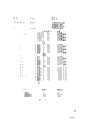
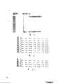
图5是一个确定对于位速率BR和抽样频率Fs的指定值来说在一个帧中的信息组B的数目的表。Fig. 5 is a table for determining the number of blocks B in one frame for specified values of the bit rate BR and the sampling frequency Fs.
图6给出了对于位速率BR的多个值来说按一个填充顺序的帧的数目以及其中包括一个附加信息组(空槽)的帧的数目。Figure 6 shows the number of frames in a stuffing sequence and the number of frames in which an additional field (empty slot) is included for various values of the bit rate BR.
图7表示在一个帧的第一帧区中所包括的系统信息。Fig. 7 shows system information included in the first frame area of a frame.
图8说明对于各种方式来说关于多个(两个)通道的数字信息的分布。Figure 8 illustrates the distribution of digital information on multiple (two) channels for various approaches.
图9说明插在第二帧区中的分配信息的意义。Fig. 9 illustrates the meaning of allocation information inserted in the second frame area.
图10和图11说明分别对于格式A和格式B两种格式来说分配信息被存入第二帧区时所用的顺序。Figures 10 and 11 illustrate the order in which allocation information is stored in the second frame area for two formats, format A and format B, respectively.
图12表示一个接收机的例子。Fig. 12 shows an example of a receiver.
图13表示一个以一个装置的形式的发射机,该装置用于在磁记录载体上记录第二数字信号。Figure 13 shows a transmitter in the form of a device for recording a second digital signal on a magnetic record carrier.
图14表示一个以一个装置的形式的接收机,该装置用于从一个磁记录载体上再生第二数字信号。Figure 14 shows a receiver in the form of an apparatus for reproducing a second digital signal from a magnetic record carrier.
图15a到图15d表示在一个帧的第三帧区中包括比例因子和抽样的一些另外的可能性。Figures 15a to 15d show some further possibilities for including scaling factors and sampling in the third frame region of a frame.
图16表示这个发射机的一个进一步改进。Figure 16 shows a further improvement of this transmitter.
图17表示一个帧的第一帧区的另一种结构。Fig. 17 shows another structure of the first frame area of a frame.
图18表示在图17所示的第一帧区中包括的系统信息。FIG.18 shows system information included in the first frame area shown in FIG.17.
图19和图20更详细地表示在图17所示的第一帧区中的信息。19 and 20 show the information in the first frame area shown in FIG. 17 in more detail.
图21和图22说明这样一种顺序,按这种顺序分配信息存在于和图17第一帧区相关的第二帧区中。FIGS. 21 and 22 illustrate the order in which allocation information exists in the second frame area associated with the first frame area of FIG. 17. FIG.
图23给出填充有一个附加信号的一个帧的结构。Fig. 23 shows the structure of a frame filled with an additional signal.
图24说明比例因字是怎样得出的。Figure 24 illustrates how the proportional factor word is derived.
图25说明已确定比例的抽样的量化,从而形成q位数字表示。Figure 25 illustrates the quantization of scaled samples to form a q-bit digital representation.
图26说明q位数字表示的去除量化。Figure 26 illustrates dequantization of q-bit digital representations.
图1图解表示了由发射机产生的并且经由传送介质传送的第二数字信号。第二数字信号采取串行数字数据流的形式。第二数字信号包括多个帧,它们是两个这样的帧,即如图1a所示的帧j和帧j+1。这些帧,诸如帧j包括多个如图1b所示的信息组IP1、IP2.IP3……。每个信息组,诸如IP3,包括如图1c所示的N位b0、b1.b2、……、bn-1。在一个帧中的信息组的数目取决于(a)位速率BR,第二数字信号以这个位速率BR经由传送介质质来传送。Fig. 1 diagrammatically represents a second digital signal generated by a transmitter and transmitted via a transmission medium. The second digital signal takes the form of a serial digital data stream. The second digital signal comprises a plurality of frames, which are two such frames, namely frame j and frame j+1 as shown in Fig. la. These frames, such as frame j, comprise a plurality of packets IP1 , IP2 .IP3 . . . as shown in Fig. 1b. Each packet, such as IP3 , includes N bits b0 , b1 .b2 , . . . , bn-1 as shown in Fig. 1c. The number of packets in a frame depends on (a) the bit rate BR at which the second digital signal is transmitted via the transmission medium.
(b)在一个信息组中位的数目N,N大于1,(b) the number N of bits in a block, N being greater than 1,
(c)Fs,它是宽带数字信号的抽样频率,(c) Fs, which is the sampling frequency of the wideband digital signal,
(d)宽带数字信号的抽样的数目ns符合于这个数字信号并且在发射机中的转换以后属于第二数字信号的信息以下述方式被包括在一个帧中。参数P依照下述公式来计算:(d) The number ns of samples of the wideband digital signal corresponds to this digital signal and the information belonging to the second digital signal after conversion in the transmitter is included in a frame in the following manner. The parameter P is calculated according to the following formula:
如果这个计算对于P来说产生了一个整数,那么在一个帧中的信息组B的数目将等于P。如果这个计算没有得出一个整数,那么一些帧将将包括P′个信息组而其它帧包括P′+1个信息组。P′是跟随P的下一个较低的整数。包括P′和P′+1个信息组的帧的数目以这样一种方式即平均帧速率等于Fn/ns的方式清楚地进行选择。下文假定N=32而ns=384。图5的表给出了对于N和ns这些值以及位速率BR的四个值以及抽样频率Fs的三个值来说,在一个帧中的信息组(槽)的数目。显然,对于抽样频率Fs等于44.1KHz来说参数P在所有的情况下都不是整数,因此许多帧包括34个信息组,而其它帧则包括35个信息组(当BR是128千位/秒时)。这还由图2来说明。图2表示一个帧。这个帧包括P′个信息组IP1、IP2、……、IPP′。有时一个帧包括P′+1个信息组。这可通过把一个附加的信息组(空槽)分配给P′信息组的帧来实现。图6表中的第二列给出了按44.1KHz抽样频率以及上文所述四个位速率来说的填充顺序中帧的数目。第三列确定了包括P′+1个信息组的顺序中的所说帧数目的那些帧。通过把第二和第三列中的数目相减就得出了包括P′个信息组的顺序中的帧的数目。而且第P′+1个信息组不必包含任何信息。第P′+1个信息组此外可以仅仅包括例如零。显然位速率BR不必限于图5和图6表中给出的四个数值。其它数值(例如中间值)也是可能的。图2表示一个帧包括以这个次序的三个帧区FD1、FD2和FD3。第一个帧区FD1包含同步信息和系统信息。第二个帧区FD2包含分配信息。第三个帧区FD3包含抽样,并且在可应用时包含第二数字信号的比例因子。为了进一步地解释,有必要首先描述按照本发明的传送系统的发射机的操作。If this calculation yields an integer for P, then the number of packets B in a frame will be equal to P. If this calculation does not result in an integer, then some frames will contain P' packets and other frames will contain
图4图解说明了这个传送系统,它包括一个发射机1,它具有一个用于接收宽带数字信号SBB的输入终端2,信号SBB例如可以是一个数字声频信号。在声频信号的情况下它可以是一个单声信号或者是一个立体声信号。在立体声信号的情况下该数字信号包括第一(左通道)和第二(右通道)信号成分。假定这个发射机包括一个用于宽频带数字信号的分频带编码的编码器,并且假定这个接收机因此而包括一个用于接收该宽频带数字信号的分频带译码器。这个发射机包括分析滤波器装置3,它响应数字宽频带信号SBB而产生多个M分频带信号SSB1到SSBM,这个分析滤波器装置用抽样频率压缩把宽频带信号SBB的信号频带分割成为具有频带数目M(1≤m≤M)的连续的分频带,数M随频率而增加。所有这些分频带可以有相同的带宽,但是另一方面,这些分频带也可以有不同的带宽。在那种情况下分频带例如可以符合人耳的临界频带的带宽。这个发射机还包括用于一个字块一个字块地量化各个分频带信号的装置。这些量化装置由图4中带有参考号9的方框来表示。Figure 4 illustrates the transmission system, which comprises a
这样的一种分频带编码器本身是已知的,尤其在前面提到的Krasner和Theile et al的出版物中已作了叙述。还可以参考已分布的289,080号欧洲专利申请(PHN.12.108)。Such a subband coder is known per se, and is described inter alia in the aforementioned publications of Krasner and Theile et al. Reference is also made to distributed European Patent Application No. 289,080 (PHN.12.108).
为了进一步说明分频带编码器的操作请参看所说的出版物。这些出版物因此在这里被参考引用。这样的一个分频带编码器使重要的数据压缩能够得以实现,例如对于宽带数字信号SBB从每个抽样16位压缩到例如在这个信号中每个抽样4位,它经由图4的传送介质4传送给接收机5。假定上述的ns是384。这意味着存有宽带数字信号的384个抽样的字块,每个抽样的长度为16位。现在还假定M=32。因此,宽带数字信号在分析滤波器装置3中被分裂成为32个分频带信号。现在分频道信号的32个字块出现在分析滤波器装置的32个输出端上,每个字块包括12个抽样(这些分频带具有相等宽度),每个抽样具有16位的长度。这意味着在滤波器装置3的输出端上信息内容仍然等于在输入端2上的信号SBB的384个抽样的字块的信息内容。装置9提供了数据压缩,其中通过采用有关屏蔽的知识,使12抽样中的32个字块中的抽样(一个分频带有一个字块)都被更加粗略地量化了,从而可由较小数目的位来代表。在静态位分配的情况下每个帧的每个分频带的全部抽样都由固定数目的位来表示。这个数目对于两个或多个分频带来说可以是不同的,但是对于多个分频带来说它也可以是相等的,例如等于4个位。在动态位分配的情况下对于每个分频带来说所选择的位的数目以时间的角度来看可以是不同的,所以用相同的位速率有时可以获得甚至更大的数据压缩或者可以获得较高的音质。For a further description of the operation of the subband coder refer to said publication. These publications are hereby incorporated by reference. Such a subband coder enables significant data compression, e.g. from 16 bits per sample to e.g. sent to
在装置9中被量化的分频带信号被施加给一个产生器装置6。这个装置6从已量化的分频带信号出发产生了如图1和图2所示的第二数字信号。这个第二数字信号如上文所述可经由介质直接传送。然而,这个第二数字信号最好首先适宜于在一个信号转换器(未示出)上经由传送介质4传送。这样的一个数字转换器包括例如一个8位到10位的转换器。这样的一个8位到10位的转换器例如在150,082号(PHN.11.117)欧洲专利申请中给出了说明。这个转换器把8位数据字转换成为10位数据字。此外,这样的一个信号转换器使交叉处理能够得以应用。所有这些的目的是使在接收侧要接收的信息能够进行错误校正。The subband signal quantized in
显然,接收机5从传送介质4接收的信号应被去除交叉并进行10位到8位的转换。Obviously, the signal received by the
现在将更详细地解释这些帧的组成和内容。图3更详细地表示了图2的第一帧区FD1。图3清楚地表示出,现在第一帧区正好包括32位,因此正好等于一个信息组,即这个帧的第一个信息组IP1。这个信息组的前16位构成同步信号(或者同步字)。这个同步信号例如可以只包括一些“1”。位16到位31表示系统信息。位16到位23表示在一个帧中的信息组的数目。因此对于包括P′个信息组的帧和包括附加信息组IPP′+1的帧来说,这个信息组数目与P′相一致。为了避免与同步信号相类似,P′最多可以是254(按位的记法是11111110)。位24到位31提供了帧格式信息。图7给出了信息的这个安排和意义的一个例子。位24指示帧的类型。在格式A的情况下第二帧区具有与在格式B的情况下不同的长度(不同数目的信息组)。正如下文将要明显说明的那样,在A格式中的第二个帧区FD2包括8个信息组,即包括信息组IP2到IP9在内,而在B格式中它包括4个信息组,即包括信息组IP2到IP5在内。位25和位26指示是否允许复制信息。位27到位31指示功能方式。这意味着:The composition and content of these frames will now be explained in more detail. FIG. 3 shows the first frame area FD1 of FIG. 2 in more detail. Fig. 3 clearly shows that the first frame field now contains exactly 32 bits and therefore exactly equals one packet, ie the first packetIP1 of this frame. The first 16 bits of this information group constitute a sync signal (or sync word). This synchronization signal may, for example, only contain some "1s".
a)通道方式,指示宽带信号的类型(如上文所述这可以是一个立体体声信号、一个单声信号、或者包括两种不同信号成分例如代表相同文本但是采用两种不同语言的一个声频信号)。图8表示通道方式。它图解说明了在上文所述的情况下信号成分在两个通道之间是怎样被分割的。a) channel mode, indicating the type of broadband signal (as stated above this could be a stereo signal, a mono signal, or an audio signal comprising two different signal components e.g. representing the same text but in two different languages ). Fig. 8 shows the channel mode. It illustrates how the signal components are split between the two channels in the situation described above.
b)宽带信号的抽样频率Fs。b) The sampling frequency Fs of the broadband signal.
c)加重,它可放到发射机的宽带数字信号上。数值50μs和15μs是加重和CCITT J的时间常数。数值17表示由CCITT(国际电报和电话咨询委员会)确定的一个特定的重点标准。c) Emphasis, which can be placed on the wideband digital signal from the transmitter. The
现在将参照图9、图10和图11更详细地描述图2中帧区FD2的内容。在A格式中第二帧区包含8个信息组。这是因为假定宽带数字信号SBB被转换成为32个分频带信号(对于数字信号SBB的每个信号区)。把一个具有4位长度的分配字分配给每个分频带。这产生了总共64个分配字,每个字具有4位的长度,它们正好可被容纳在8个信息组中。在B格式中第二帧区仅容纳一半数目的分频带的分配信息,因此现在第二帧区只包括4个信息组。图9说明了4位分配字AW的意义。与一个特定分频带有关的一个分配字确定了位的数目,在装置9中进行量化以后在有关分频带中的分频带信号的抽样就由这个数目来代表。例如:分配字AW是0100,它表示抽样由5位字来代表。此外,从图9得出,分配字0000表示在有关分频带中不产生抽样。例如,如果一个相邻分频带中的分频带信号具有这样大的一个幅度以致于这个信号全部掩蔽了有关分频带中的分频带信号,那么这种情况就可能发生。此外,不使用分配字1111,因为它太类似于第一信息组IP1中的同步字。图10表示在这样一种情况下的序列:帧方式是A,其中分配字是AW、j、m,它与两个通道j有关,j=Ⅰ或Ⅱ,序列数为m的32个分频带,m的范围为1到32,它们都被排列在第二帧区中。分配字AWI、1属于第一个和最低的分频带(通道Ⅰ、分频带1)的第一个分频带信号成分,它首先被插入。在此之后,属于第一个和最低的分频带(通道Ⅱ、分频带1)的第二个分频带信号成分的分配字AWⅡ、1被插入第二帧区FD2中。接着,属于第二个和除一个分频带之外最低的分频带(通道Ⅰ、分频带2)的第一个分频带信号成分的分配字AWⅠ、2被插入帧区FD2中。接着是属于第二个分频带(通道Ⅱ、分频带2)的第二个分频带信号成分的分配字AWⅡ、2。就这样继续下去直到属于第四个分频带(通道Ⅱ、分频带4)的第二个分频带信号成分的分配字AWⅡ、4被插入第二帧区FD2中。这个帧的第二个信息组IP2(槽2)是这个帧的帧区FD2中的第一个信息组,于是它正好被填充。接着,信息组IP3(槽3)用AWⅠ、5;AWⅡ、5;……AWⅡ、8填充。就这样按图10所示的顺序继续下去。图10仅给出了被插入的分配字AW、j、m的示数j-m。图11表示对于在一个B格式帧的情况下分配字的顺序。在这种情况下只插入分频带1至16的分配字。图10所示的顺序符合于这样一种顺序即属于一个通道j和一个分频带m的这些分离的抽样一旦在接收机接收时就被施加给合成滤波器装置。这将在下文更详细地进行解释。串行数据流例如仅包含符合了A格式的帧。在接收机中每个帧的分配信息被用于从所说帧的第三帧区中的信息正确地得出抽样。然而,串行数据流还可以大体上交替地包括符合了A格式的帧和符合了B格式的帧。然而,符合于两种格式的帧可以包含对于全部通道和第三帧区中的全部分频带的抽样。一个符合于B格式的帧因此事实上缺少为从一个B格式帧的第三帧区中得出对于分频带17至32的通道Ⅰ或Ⅱ中的抽样所需要的分配信息。接收机包括一个存器,可把在一个A格式帧的第二帧区中包括的分配信息贮存在该存贮器中。如果下一个帧是B格式帧,那么在该存贮器中只有对于分频带1至16和通道Ⅰ和Ⅱ的分配信息被B格式帧的第二帧区中包括的分配信息替换,并且为了从B格式帧的第三帧区中得出对于分频带17至32的抽样,就要利用从前一个A格式帧中得出的、并且仍然存在于存贮器中的这些分频带的分配信息。交替使用A格式帧和B格式帧的理由是,对于某些分频带来说,在对于较高分频带17至32的分配信息的现在的情况下,分配信息不能迅速地改变。既然在量化期间已经知道在发射机中可以得到各个分频带的分配信息,那么如果包括分频带17至32在内的分配信息不改变(显著地),这个发射机就能够确定产生一个B格式帧而不是一个A格式帧。此外,这说明附加的空间现在对于包括第三帧区FD3的抽样来说成为可以利用的了。对于P′的一个特定值来说一个B格式帧的第三帧区比一个A格式帧的第三帧区长4个信息组。因此,这使得位的数目增加,在较低分频带1至16中的抽样就由这些位来表示,从而对于这些分频带来说可以达到较高的传送精度。此外,如果需要更精确地量化这些较低的分频带,发射机可以自动地挑选B格式帧的产生。这可能是以消耗量化较高分频带所具有的精确度来作为代价的。The contents of the frame area FD2 in FIG. 2 will now be described in more detail with reference to FIGS. 9 , 10 and 11 . In the A format the second frame area contains 8 fields. This is because it is assumed that the wideband digital signalS BB is converted into 32 subband signals (for each signal region of the digital signalS BB ). An allocation word having a length of 4 bits is allocated to each subband. This results in a total of 64 allocation words, each 4 bits in length, which fit into exactly 8 packets. In the B format, the second frame area only accommodates half the allocation information of the sub-bands, so now the second frame area only includes 4 information groups. Figure 9 illustrates the meaning of the 4-bit allocation word AW. An allocation word associated with a particular subband defines the number of bits by which the samples of the subband signal in the relevant subband are represented after quantization in the
图2中的第三帧区FD3包含对于两个通道的量化分频带信号成分的抽样。如果这些分频带通道之中没有一个通道的帧区FD2不存在有分配字0000,那么这意味着在目前的例子中12个抽样被插在两个通道及32个分频带之中的每个分频的第三帧区FD3中。这意味着总共有768个抽样。在发射机中这些抽样可在进行量化之前和一个比例因子相乘。对于这些分频带和通道之中的每一个分频带和通道来说,12个抽样的幅度被这12个抽样之中具有最大幅度的那个抽样的幅度来分割。在这种情况下,对于每一个分频带和每一个通道来说应该传送一个比例因子,以便在接收端抽样时使逆操作能够得以进行。为了这个目的,第三帧区因此包含比例因子SF j、m,每一个比例因子都相对于各个分频带中的每一个量化分频带信号成分。在本实例中,比例因子都由6位数字表示,最高有效位开始,数值范围从000000到111110。分配给这些分频带的比例因子(即它们的分配信息不是零)要在这些抽样的传送开始进行之前被发送。这意味着这些比例因子被存放在这些抽样前面的第三帧区FD3的引导部分中。这使得不必在接收机中贮存全部抽样就能够实现接收机5的快速译码,正如下文将要明显叙述的那样。比例因子SF j、m因此可以表示这样的数值,即在第m个分频道的第j个通道中的信号的抽样已被这个数值相乘了。相反地,将数字1除以所说数值作为比例因子贮存,以便在接收端不必去除以在抽样前面的比例因子,就可按比例放大到正确的数值。The third frame area FD3 in Fig. 2 contains samples of the quantized sub-band signal components for both channels. If frame field FD2 of none of these sub-band channels does not have
对于帧格式A来说最大数目的比例因子是64。如果对于一个确定通道j和一个确定分频带m的分配字AW j、m具有数值0000,这就意味着对于这个通道和这个分频带来说没有抽样存在于帧区FD3中,则不必包括对于这个通道和这个分频带的比例因子。比例因子的数目因此小于64。比例因子SF j、m被插在第三帧区FD3中的顺序与分配字已被插在第二帧区中的顺序相同。这个顺序因此如下所示:The maximum number of scale factors for frame format A is 64. If the allocation word AW j,m for a certain channel j and a certain frequency subband m has the
SFⅠ、1;SFⅡ、1;SFⅠ、2;SFⅡ、2;SFⅠ、3;SFⅡ、3;……SFⅠ、32;SFⅡ、32。SFI, 1; SFI II, 1; SFI, 2; SFI II, 2; SFI, 3;
如果不必插入一个比例因子,那么这个顺序就是不完全的。于是这个顺序例如可以是:The sequence is not complete without having to interpolate a scaling factor. The sequence can then be, for example:
……SFⅠ、4;SFⅠ、5;SFⅡ、5;SFⅡ、6……...SFⅠ, 4; SFⅠ, 5; SFⅡ, 5; SFⅡ, 6...
在这种情况下没有插入对于通道Ⅱ的第四个分频带和通道Ⅰ的第六个分频带的比例因字。如果这个帧是一个B格式的帧,那么仍然可以认为在第三帧区中插入了对于全部分频带和全部通道的比例因子。然而这不是必要的。在这种情况下在这个帧的第三帧区中只插入对于分频带1至16的比例因子也是可能的。在接收机中这需要一个存贮器,全部比例因子可在接收到一个在先到达的A格式帧的这个瞬间被存入这个存贮器中。接着在接收到B格式帧的时候,只有分频带1至16的比例因子被B格式帧所包括的比例因子替换。为了使B格式帧的第三帧区所包括的这些分频带的抽样复原到正确的比例,于是使用在先接收的A格式帧对于分频带17至32的比例因子。The scale factor words for the fourth subband of channel II and the sixth subband of channel I are not inserted in this case. If the frame is a B-format frame, it can still be considered that scale factors for all sub-bands and all channels are inserted in the third frame area. However this is not necessary. In this case it is also possible to insert only the scale factors for
抽样插入第三帧区FD3中的顺序与分配字和比例因子的顺序相同,对应于相继的每个通道的每个分频带都有一个抽样。即,首先是对于两个通道的所有分频带的量化分频带信号的所有第一个抽样,然后是所有第二个抽样,……等等。这些抽样的二进制表示是任意的,最好不再使用只包括“1”的二进制字。The samples are inserted in the third frame area FD3 in the same order as the allocation words and scale factors, one sample for each subband for each successive channel. That is, first all first samples of the quantized subband signal for all subbands of both channels, then all second samples, . . . and so on. The binary representation of these samples is arbitrary and it is preferable not to use binary words consisting only of "1".
由发射机1产生的第二数字信号然后经由输出端7被施加到传送介质4,这个信号再利用传送介质4传送给接收机5。经由传送介质4的传送可以是例如无线电传送通道的无线传送。然而,其它传送介质也是可能的。在这方面可以设想光学传送,例如经由光学纤维或者诸如小型盘状介质的光学记录载体,或者利用RDAT或SDAT类的记录和复制技术的磁记录载体的传送,对于这方面可参考书籍“The art of digital audio”(J.Watkinson,Focal Press,London,1988)。The second digital signal generated by the
接收机5包括一个译码器,它对在发射机1的编码器6中编码的信号进行译码,并且把它转换成为这个宽带数字信号的复制品,从而提供给输出端8。The
图12表示图4中接收器5的一个更具体的方案。编码信号(第二数字信号)经由终端10施加给装置11。输入信号中的基本信息被包含在比例因子和抽样中。第二数字信号中的剩余信息仅被要求用于“校正薄记”,以便使正确的译码能够进行。对于每个输入帧来说都重复译码过程。发射机首先从这些帧中得出同步和系统信息。装置19每次都检测位于每个帧的第一帧区的前16位中的同步字。既然这些连续帧的同步字每次都被一个整数倍的P′或P′+1个信息组隔离开,所以可以非常精确地检测这些同步字。一旦接收器处于同步状态,同步字就可在装置19中得到检测,在这种情况下装置19有一个时间窗口,它具有例如一个信息组的长度,这个时间窗口每次在P′信息组之后打开,所以只有那个部分的输入信号被施加给装置19中的同步字检测器。如果没有检测到同步字;那么在另一个信息组的持续期间时间窗口仍然保持打开状态,因为前一个帧可能是一个包括P′+1个信息组的帧。装置19中的一个PLL可以从这些同步字中得出一个时钟信号,从而控制中心处理机18。从上文叙述中显然可以得知,接收机应该知道在一个帧中包含多少信息组。为了这个目的,系统信息经由处理机18的输入端被提供给开关装置15,这个开关装置因此要处于图中所示的位置上。那么系统信息就可被贮存在处理机18的一个存贮器18a中。这个关于一个帧的信息组数目的信息可经由控制信号线20而被提供给装置19,以便在同步字检测的恰当瞬间打开时间窗口。当接收到系统信息时开关15就转换到较低位置。在这个帧的第二帧区中的分配信息于是可被贮存在存贮器18b中。如果输入帧中的分配信息不包括一个对于全部分频带和通道的分配字,那么这在所检测的系统信息中就已经是很明白的了。例如这可以是指出这个帧是一个A格式帧还是一个B格式帧的信息。这样,在系统信息中包含的有关信息的影响下,处理机18中将在分配存贮器18b中的恰当位置上贮存所接收的分配字。很明显,在本实例中分配存贮器18b包括64个存贮位置。如果不发送比例因子,就可以省去由参考号11、12和17指示的部件,一个帧的第三帧区中的内容就经由输入端10而提供给合成滤波器装置,输入端10经由连接线16耦连到所说滤波器装置的输入端。为了再生这个宽带信号,把抽样提供给滤波器装置21的顺序与滤波器装置21处理这些抽样的顺序相同。为了在滤波器装置21中把抽样的串行数据流分割成为各个抽样,每个抽样具有恰当数目的位,就需要在存贮器18b中贮存的分配信息。为了这个目的,分配信息经由线路22提供给滤波器装置21。接收机还包括一个去除加重装置23,它使由滤波器21提供的再生数字信号经受去除加重处理。为了正确的去除加重,在第一帧区的位24至31中的有关信息应经由线路24从存贮器18a中提供给去除加重装置23。FIG. 12 shows a more specific version of the
如果第三帧区也包含比例因子SF j、m,那么接收机将包括开关11、存贮器12和乘法器17。在一个帧的第三帧区FD3到达的所有时刻,在经由导线13被处理机18提供的一个控制信号的影响下开关11处于较低位置。比例因子于是可被提供给存贮器12。在经由线路14被处理机18提供给存贮器12的地址信号的影响下,比例因子被贮存在存贮器12中的恰当位置上。存贮器12具有64个用于存贮64个比例因子的位置。当再次接收到一个B格式帧时,处理机18把这样的地址信号提供给存贮器12以便使仅仅分频带1至16的比例因子被这个B格式帧的比例因子所改写。接着,开关11在经由线路13提供的控制信号的影响下转换到所示(较高的)位置,以使抽样提供给乘法器17。在这时经由线路22提供给乘法器17的分配信息的影响下,乘法器首先从经由线路16提供的串行数据流中得出合适位长度的各个抽样。然后,这些抽样被加倍以使它们复原到在发射机中按比例缩小之前这些抽样的正确数值。如果在存贮器12中贮存的比例因子是这样的比例因子,即这些抽样已经在发射机中按这样的比例因子缩小比例,那么这些比例因子首先应取倒数(1被该比例因子除),然后应被提供给乘法器17。显然,在比例因子被贮存在存贮器12之前的接收时候取这些比例因子的倒数也是可能的。如果在这些帧中的比例因子已经等于这样的数值,即这些抽样应在接收期间按所说数值放大比例,那么它们可被直接贮存在存贮器12中并且可被直接提供给乘法器17。很明显,在根据帧中包含的抽样进行的信号处理开始之前不要求存贮器贮存所有这些抽样。在一个抽样经由线路16到来的这个时刻,所有的为了处理这个抽样而要求的信息都已经可以得到了,所以可以立刻进行处理。这个总过程是在由处理机18提供给发射机所有部分的时钟信号和控制信号的作用下而进行的。图中并未示出所有的控制信号。这样做是不必要的,因为对于该技术领域的技术人员来说接收机的操作是显而易见的。在处理机18的控制下乘法器17按照合适的倍乘因子去乘这些抽样。现在这些已经被复原到正确幅度的抽样被提供给再生滤波器21,在滤波器21中这些分频带信号被再次转变成为宽带数字信号。不必要对接收机作进一步说明,因为这样的接收机一般是已知的,如参见出版物”Low bit rate coding of hing-qualityaudio signals.An introduction to the MASCAM System”(G.Theile et al in EBU Technical Review,No.230,August 1988)。此外,很明显,如果系统信息也被发送,那么接收机就能够高度灵活并且能够对这些信号进行正确译码,即使在具有不同系统信息的第二数字信号的情况下也是如此。If the third frame area also contains scale factors SF j,m, then the receiver will comprise a
图13还图示了发射机的另一个实施例,现在它采取用于在记录载体上记录宽带数字信号的一个记录装置的形式,在本例中该记录载体是一个磁记录载体25。编码器6把第二数字信号提供给一个记录装置27,记录装置27包括一个写入头26,利用写入头26就把信号记录在这个记录载体的一个磁道上。例如通过一个螺旋扫描记录器就可以把第二数字信号记录在记录载体的单个磁道上,在这种情况下单个磁道事实上被划分为多个并列磁道,这些并列磁道相对于记录载体的纵向方向是倾斜的。其中的一个例子是一种RDAT样的记录方法。另一种方法是分裂信息并且在多个并列磁道上记录该分裂信息,这些并列磁道在记录载体上沿记录载体的纵方向延伸。为此可以考虑使用一种SDAT样的记录方法。上述两种方法的全面说明可从前面提到的由J.Watkinson著的书“The art of a digital audio”中得知。另一方面要注意,由装置6提供的信号首先可在一个信号转换器中编码。这种编码仍然可以是如参照图4所叙述的8位到10位的转换,接着是交叉过程。如果编码信息被记录在记录载体上的多个邻接的并列磁道中,那么这个信号转换器还应该能够把编码信息分配给各个磁道。Figure 13 also illustrates another embodiment of the transmitter, which now takes the form of a recording device for recording broadband digital signals on a record carrier, in this case a
图14图解表示了接收机5的一个实施例,它在本例中采取用于读出记录载体25的一个读出装置的形式,在这个记录载体25上已经利用图13所示的装置以第二数字信号的形式记录了宽带数字信号。第二数字信号通过读出头29从记录载体上的一个磁道中读出并且被提供给接收机5,接收机5例如可以是如图12所示的一种结构。另一方面读出装置28可被设计为执行一种RDAT样的或者SDAT样的再生方法。两种方法同样在前面提到的Watkinson著的书中作了全面的说明。如果对在图13所示的记录装置中由装置6提供的信号已经进行了例如8位到10位的转换以及交叉步骤,那么从记录载体25中读出的编码信号首先应被去除交叉然后应经过10位到8位的转换。此外,如果编码信号已被记录在多个平行磁道上,那么图14所示的再生装置就应该在进一步的处理被施加之前把从这些磁道中读出的信息按恰当的顺序进行排列。Fig. 14 diagrammatically shows an embodiment of the
图15表示把比例因子和抽样插入一个帧的第三帧区FD3中的多个其它可能性。图15a说明了上文所述的方法,对于所有分频带m和通道(Ⅰ或Ⅱ)的比例因子SF就用这种方法插在第三帧区中的抽样之前。图15b说明了与图15a相同的情况,但是在这个情况下它图解表示了对于在分频带m中两个通道的比例因子SFⅠ、m和SFⅡ、m以及有关的X个抽样的存贮能力。图15b表示对于结合为字块的分频带m中两个通道的抽样,通常它们被分配在第三帧区中。这些抽样具有y个位的长度。在上述例子中X是12而y则取为8。图15c表示另一种格式。对于分频带中第一和第二通道的两个比例因子仍然存在于第三帧区中。然而不是对于分频带m(即总共2X个抽样)中两个通道(立体声信号的左和右通道)的X个抽样而只是对于分频带m的X个抽样被包括在第三帧区中。这些个X抽样例如通过把在两个通道中的每一个通道的对应抽样相加来获得。事实上,在这个分频带m中获得了一个单声信号。图15c中的X个抽样各有z个位长度。如果z等于y就节省了第三帧区中的空间,它于是可被用于需要更精确量化的那些抽样。另一方面能够用z=2y(=16)位来表示单声信号的X个抽样。如果在一个分频带中的左侧和右侧信号成分之间的相位差是不相关的但单声信号的波形是重要的,那么就进行这样一种信号处理。这特别适于较高分频带的信号,因为人耳的相位灵敏度对于这些分频带中的频率来说比较低。通过用16位来表示单声信号的X个抽样,就可以更精确地量化波形,而在第三帧区中这些抽样所占据的空间等于在图15b所示例子中的空间。还有另一个可能性就是例如用12位来表示图15中的抽样。这样信号的确定就比图15b所示的例子更精确,同时另外还节省了第三帧区中的空间。当图15c所示的第三帧区所包括的这些信号在接收端再生时,就获得了被称为“强度立体”的立体效果。这里,由于比例因子SFⅠ、m和SFⅡ、m的不同数值,只有左通道和右通道中信号(在分频带m中)的强度可以不同。Fig. 15 shows several other possibilities for inserting scale factors and samples in the third frame field FD3 of a frame. Figure 15a illustrates the method described above by which the scale factors SF for all subbands m and channels (I or II) are inserted before the samples in the third frame area. Figure 15b illustrates the same situation as Figure 15a, but in this case it diagrammatically represents the storage capacity for the scale factors SFI,m and SFII,m and the associated X samples for two channels in subband m. Figure 15b shows samples for two channels in sub-band m combined as blocks, which are usually allocated in the third frame area. These samples have a length of y bits. X is 12 and y is taken as 8 in the above example. Figure 15c shows another format. The two scale factors for the first and second channels in the subband still exist in the third frame area. However instead of X samples for both channels (left and right channels of the stereo signal) in subband m (ie 2X samples in total) only X samples for subband m are included in the third frame area. These X samples are obtained, for example, by adding corresponding samples in each of the two channels. In fact, a mono signal is obtained in this subband m. The X samples in Figure 15c are each z bits long. If z is equal to y, space is saved in the third frame area, which can then be used for those samples that require more accurate quantization. On the other hand it is possible to represent X samples of a monophonic signal with z=2y (=16) bits. Such signal processing is performed if the phase difference between the left and right signal components in a subband is irrelevant but the waveform of the monaural signal is important. This is especially true for higher sub-band signals, since the phase sensitivity of the human ear is relatively low for frequencies in these sub-bands. The waveform can be more accurately quantized by representing X samples of the monophonic signal with 16 bits, and these samples occupy a space in the third frame area equal to that in the example shown in Fig. 15b. Yet another possibility is to represent the samples in Fig. 15 eg with 12 bits. This results in a more precise determination of the signal than in the example shown in Fig. 15b, while additionally saving space in the third frame area. When these signals included in the third frame area shown in Fig. 15c are reproduced at the receiving end, a stereoscopic effect called "intensity stereo" is obtained. Here, due to the different values of the scaling factors SFI,m and SFII,m, only the strength of the signal (in subband m) in the left and right channel can differ.
图15d还给出了另一种可能性。在这种情况下对于分频带m中的两个信号成分只有一个比例因子SFm。这种情况特别对于低频分频带来说可能发生。还有另一种可能性图中没有示出,即对于图15b中分频带m的通道Ⅰ和通道Ⅱ来说的X个抽样没有相关的比例因子SFⅠ、m和SFⅡ、m。因此,这些比例因子不插在同一个第三帧区中。在这种情况下由前一个帧的第三帧区包括的比例因子SFⅠ、m和SFⅡ、m必须用于在接收机中按比例放大这些抽样。Figure 15d also presents another possibility. In this case there is only one scaling factor SFm for the two signal components in subband m. This can happen especially for low frequency crossover bands. Yet another possibility, not shown in the figure, is that the X samples for channel I and channel II of subband m in Fig. 15b have no associated scale factors SFI,m and SFII,m. Therefore, these scale factors are not interpolated in the same third frame area. In this case the scaling factors SFI,m and SFII,m contained by the third frame area of the preceding frame must be used to scale up the samples in the receiver.
所有这些参照图15叙述的可能性都可被用于发射机,以便经由传送介质实现最有效的数据转送。这样,参照图15描述的这些帧可以交替地发生在数据流中。可以设想,如果接收机还能够正确地给这些不同的帧译码,那么在系统信息中就应该包括关于这些帧的结构的信息。All of these possibilities described with reference to Figure 15 can be used at the transmitter in order to achieve the most efficient data transfer via the transmission medium. In this way, the frames described with reference to FIG. 15 may alternately occur in the data stream. It is conceivable that if the receiver is also able to correctly decode these different frames, then information about the structure of these frames should be included in the system information.
图16更详细地表示了发射机。这个图表示各项信息怎样能被结合形成如图1、2和3给出的串行数据流。图16事实上表示在发射机1中编码器6的一种更详细的形式。这个编码器包括一个中心处理机30,它控制编码器中的多个装置。这个编码器包括一个位于处理机30中的产生器31,它用于产生参照图3所述的同步信息和系统信息,还包括一个产生器32用于确定分配信息,还包括一个产生器33(任选的)用于确定比例因子,还包括一个产生器34用于确定一个帧的抽样。产生器35能够产生附加信息组IPP′+1。这些产生器的输出端被耦连到取5位开关形式的开关装置40的有关输入端,开关装置40的输出端被耦连到编码器6的输出端7。开关装置40还可由处理机30来控制。经由线路41.1至41.4来控制各个产生器。现在将针对一个被分割为M个分频带信号的单声信号来叙述这个发射机的操作。这些M个分频带信号SSB1至SSBM被提供给终端45.1、45.2……、45.M。例如,这些分频带信号中的每个分频带信号的12个抽样的字块被一起取用。在装置46.1至46.M中,相对于一个字块中最大抽样的幅度来改变这个字块中的12个抽样(如果存在的话)的比例。经由线路47.1至47.M来把M个比例因子提供给装置33(如果存在的话)。这些分频带信号被提供给M个量化器48.1至48.M和一个装置49。对于每个分频带,装置49确定应该量化的有关分频带信号的位的数目。这个信息经由线路50.1至50.M提供给各自的量化器48.1至48.M,从而使这些量化器正确地量化这些分频带信号中的每个信号的12个抽样。此外这个(分配)信息还被提供给装置32。这些量化分频带信号的抽样经由线路51.1至51.M提供给装置34。装置32、33和34把分配信息、比例因子和抽样排列在恰当的顺序中,即按前面叙述的顺序。此外,处理机30已经产生了有关要被生成的帧的同步信息和系统信息,在这些信息中应该插入装置32、33和34中贮存的所说信息。在图中所示的开关装置40的位置上从产生器31提供对于一个帧的同步和系统信息并且输送到输出端7。接着,开关装置40在CPU30经过线路53提供的控制信号的作用下自顶部位置开始被设置在第二个位置上,以便使产生器32的输出端被耦连到输出端7。这样分配信息就由产生器32提供到输出端7。分配信息的顺序如同参照图10或11所叙述的顺序。在此之后开关40被设置到从顶部开始的第三个位置上。这意味着产生器33的输出端被耦连到输出端7。于是产生器33就按恰当顺序把比例因子提供到输出端7。开关40然后被设置到下一个位置,以使产生器34的输出端被耦连到输出端7。于是产生器34把在恰当顺序中的各个分频带的抽样提供到输出端7。用这种循环方式就恰好把一个帧提供给输出端7。接着,开关40被重新设置到顶部位置。于是开始一个新的周期,在这个周期中对于每个分频带的12个抽样的一个随后的字块被编码,并且在输出端7可以生成一个后来接着的帧。在某些情况下,例如参见图5,如果抽样频率Fs是44.1KHz,那么必须增加一个附加信息组(空槽,参见图2)。在这种情况下开关将从耦连产生器34的位置上转到低部位置。于是产生器35的输出端被耦连到输出端7。这样产生器35产生附加信息组IPP′+1,它被提供给输出端7。在开关40被重新设置到顶部位置以后开始新的周期。显然,如果由发射机接收的信号对于在该信号传送期间引起的错误要进行校正,那么一个特定通道的编码应被用于第二数字信号。另外,需要在第二信号传送之前调制这个第二数字信号。这样,经由传送介质传送一个数字信号,该信号可以不是直接能够作为第二信号来识别的,但该信号却是从第二数字信号导出的。另外,要注意,例如在分频带具有不同宽度的情况下,对于插在一个第三帧区的各个分频带抽样的数目可以不同,并且很可能不同。例如假定,采用分割为三个分频带的分割,一个较低分频带SB1、一个中间分频带SB2以及一个较高分频带SB3。较高分频带SB3的带宽例如为其它两个分频带的带宽的两倍。这意味着对于分频带SB3的插在第三帧区中抽样的数目同样是对于其它分频带中的每个的两倍。于是把这些抽样提供给接收机中的再生滤波器的顺序可以是:SB1的第一个抽样、SB3的第一个抽样、SB2的第一个抽样、SB3的第二个抽样、SB1的第二个抽样、SB3的第三个抽样、SB2的第二个抽样、SB3的第四个抽样、……等等。于是把这些分频带的分配信息插在第二帧区中的顺序现在是:首先SB1的分配字、然后SB3的分配字、接着SB2的分配字。这同样适用于比例因子。此外,接收机可以从这个系统信息中得出,在这种情况下这个周期包括一些组,每个组包括四个抽样,每个组包括SB1的一个抽样、SB3的一个抽样、SB2的一个抽样以及接着的SB3的另一个抽样。Figure 16 shows the transmitter in more detail. This diagram shows how various pieces of information can be combined to form the serial data streams given in Figures 1, 2 and 3. FIG. 16 in fact shows a more detailed form of the
图17表示第一帧区FD1的另一个结构。第一帧区FD1同样还正好包含32位,因此对应于一个信息组。前16位同样还构成同步信号(或者同步字)。同步字同样还可能与图3中第一帧区FD1的同步字相同。容纳在位16至位31中的信息却不同于图3中位16至位31中的信息。位b16至b19代表位速率下标(BR下标)。位速率下标是一个4位数,它的意义在图18的表中作了说明。如果位速率下标等于4位数字数“0000”,那么这表示自由格式状态,这意味着位速率是不确定的并且译码器必须单独取决于同步字以便检测一个新帧的开始。为了不干扰同步字检测,不使用4位数字数“1111”。在图18的表的第二列中位速率下标表示为对应于4位数字数的十进制数。相对应的位速率值由第一列给出。FIG. 17 shows another structure of the first frame areaFD1 . The first frame field FD1 also contains exactly 32 bits and thus corresponds to one field. The first 16 bits also constitute the sync signal (or sync word). It is also possible for the sync word to be identical to the sync word of the first frame field FD1 in FIG. 3 . The information accommodated in
位20和21代表抽样频率Fs,参见图18。
图18表示对于位b20和b21的4个可能的2位数字数以及相关的抽样频率。位22指出这个帧是包括一个空槽(在这种情况下b22=“1”)、还是不包括一个空槽(在这种情况下b22=“0”)。在位b16至b22中的信息使确定实际上有多少信息组存在在这个帧中变为可能。这还意味着第一帧区包含关于这个帧的信息组数目的信息。ns是宽带信号抽样的数目,宽带信号相应的信息属于第二数字信号并被包容在一个帧中,在本例中ns=384,当ns是已知时,就可能利用图8表中的数据、填充位b22和公式p = (BR)/(N) × (ns)/(FS) 来确定有多少信息组B存在于这个帧中。位b23是用来确定这个系统的未来的扩充的。将在下文对这个未来的扩充进行描述。目前假定这个位是“0”。这个第一帧区关于位b24到b31的内容将参照图19和20来说明。位b24和b25给出了声频信号的方式指示。Figure 18 shows the four possible 2-digit numbers for bits b20 and b21 and the associated sampling frequencies.
对于这个两位数字数的4种可能性来说,图20表示这个宽带数字信号是一个立体声信号(“00”)、一个单声信号(“11”)、一个双语言信号(“10”),还是一个强度立体声信号(“01”)。在上述的最后一个情况下,位26和27指出哪一个分频带已经按照强度立体声方法作了处理。如同前面所叙述的那样强度立体声可应用于较高分频带,因为人耳对于这些分频带中的频率来说相位灵敏性较低。位b28可被用作为一个复制权位。如果这个位是1,就意味着这个信息是版本保护的并且不应该/不能被复制。位b29可以指出这个信息是原始信息(b29=“1”),例如在预先录制的磁带的情况下,或者是已被复制的信息(b29=“0”)。位b30和b31指定加重,它可能已被应用到发射机的宽带信号,同样参见关于图7的说明。For the 4 possibilities of the two-digit number, Figure 20 shows that the wideband digital signal is a stereo signal ("00"), a mono signal ("11"), a bilingual signal ("10") , again an intensity stereo signal (“01”). In the last case above,
下文将针对在第一个帧区中由位b24到b27表示的各种方式指示来说明第二帧区FD2的另一种构形。第二帧区同样还包括4位分配字,对其意义已参照图9作了叙述。对于立体方式(b24、b25=00)和双语言方式(b24、b25=10)来说,第二帧区FD2的长度也为8个信息组(槽),并且按参照图10所述的那样来构成。在立体方式中图10中的“Ⅰ”代表例如左通道成分,而“Ⅱ”代表右通道成分。对于双语言方式来说“Ⅰ”表示一种语言,而“Ⅱ”表示另一种语言。对于单声方式来说(b24、b25=11),第二帧区FD2的长度当然只是4个信息组(槽)。图21说明对于这4个信息组(槽)2至5中的各个分频带1至32的分配字的顺序。这样,每个数值M-i代表一个4位分配字,该分配字确定了顺序数为i的这个分频带中每个抽样的位的数目,i的取值范围是从1到32。在强度立体声方式中(b24、b25=01),存在用位b26和b27指出的4种可能性,参见图20。所有这些可能性引起了第二帧区FD2的不同内容。Another configuration of the second frame section FD2 will be described below for the various mode indications represented by bits b24 to b27 in the first frame section. The second frame area also includes 4-bit allocation words, the meaning of which has been described with reference to FIG. 9 . For the stereo mode (b24 , b25 =00) and the dual language mode (b24 , b25 =10), the length of the second frame area FD2 is also 8 information groups (slots), and according to the reference figure 10 as described in the composition. "I" in Fig. 10 represents, for example, a left channel component and "II" represents a right channel component in stereo mode. For the dual language mode, "I" means one language, and "II" means another language. For the mono mode (b24 , b25 = 11), the length of the second frame area FD2 is of course only 4 fields (slots). Fig. 21 illustrates the order of allocation words for the
图22a到22d说明了第二帧区的四种不同内容。如果开关位b26、b27是“00”,那么在分频带1至4中的信号是常规的立体声信号,而在分频带5至32中的信号则是强度立体声信号。这意味着,对于分频带1至4中的左侧和右侧通道成分来说,有关的分配字应被贮存在第二帧区中。在图22a中这由连续的分配字AW(1,1);AW(R、1);AW(1、2);AW(R、2);……AW(R、4)来表示,它们被贮存在这个帧的槽2中,即第二帧区的第一个槽中。图22a只给出了分配字的下标(i-j),i等于L或R,它们分别指出左侧和右侧通道成分,而j的取值范围是从1到4,它表示分频带的顺序号。对于分频带5到32来说左侧和右侧通道成分包含相同的抽样串。唯一的区别在于一个分频带中的左侧和右侧通道成分的比例因子。因此,这样的一个分频带只要求一个分配字。分频带5至32的分配字AW(i、j)由下标M-j指示,在这里对于所有的分频带来说i因此而等于M,而j的取值范围是从5到32。Figures 22a to 22d illustrate four different contents of the second frame area. If switch bits b26 , b27 are "00", then the signals in
图22a表示需要4 1/2 个信息组来把36个分配字插在第二帧区中。如果开关位b26、b27是“01”,那么在分频带1至8中的信号将是常规立体声信号,而在分频带9至32中的信号将是强度立体声信号。这意味着对于分频带1至8中的每个分频带来说需要两个分配字AW(L、j)和AW(R、j),而对于分频带9至32中的每个分频带来说则只需要一个分配字AW(M、j)。这意味着总共需要40个分配字,它们被包括在这个帧的5个信息组(槽)中,即这个帧的IP2至IP6。这由图22b来说明。在这种情况下第二帧区FD2具有5个信息组(槽)的长度。Figure 22a shows that 4 1/2 blocks are required to insert 36 allocated words in the second frame area. If switch bits b26 , b27 are "01", then the signals in
如果开关位b26、b27是“10”,那么在分频带1至12中的信号将是常规立体声信号,而在分频带13至32中的信号将是强度立体声信号。图22c给出了带有各个分频带的分配字的第二帧区FD2的结构。为了容纳所有的分配字第二帧区现在具有5 1/2 信息组(槽)的长度。如果开关位b26、b27是“11”,那么在分频带1至16中的信号将是常规立体声信号,而在分频带17至32中的信号将是强度立体声信号。现在需要48个分配字,它们被插在第二帧区中,于是第二帧区具有6个信息组(槽)的长度,参见图22d。If the switch bits b26 , b27 are "10", then the signals in
上面关于比例因子的叙述在这里也是有效的。假定分配字0000是既不分配给这些分频带中的任何分频带也不分配给这些通道中的任何通道,那么对于立体声方式和强度立体声方式来说就都需要64个比例因子。这是因为在所有的强度立体声方式中每一个单声分频带应该具有2个比例因子,以使强度立体声对于这个分频带中的左侧和右侧通道来说能够实现,参见图15c。What was said above about the scaling factor is also valid here. Assuming that
显然,如果仍然假定分配字0000是不分配给这些分频带中的任何分频带,那么在单声方式中比例因子的数目减半,即为32。Obviously, if it is still assumed that
下面将解释确定6位比例因子的一个方法。如同前面叙述的那样,对于一个分频带通道中的每12个抽样来说,要确定具有最大绝对值的抽样。One method of determining the 6-bit scale factor will be explained below. As previously stated, for every 12 samples in a subband channel, the sample with the largest absolute value is determined.
图24a表示这个最大抽样|SmX|。记为SGN的第一位是符号位并且是“0”,因为它涉及到Smax的绝对值。这些抽样都由二的补码计数法表示。这个抽样包括K个“0”,接着是一个“1”这个24位数字数的其它位的数值是不相关的,并且可以是或者“0”或者“1”。Figure 24a shows this maximum sample |SmX |. The first bit denoted SGN is the sign bit and is "0" since it relates to the absolute value ofSmax . These samples are represented by two's complement notation. The sample consists of K '0's' followed by a '1'. The values of the other bits of the 24-bit digital number are irrelevant and can be either '0' or '1'.
现在将|Smax|乘以2K,参见图24b。接着把|Smax|·2K与一个等于010100001100000000000000的数字数DV1以及一个等于011001100000000000000000的数字数DV2进行比较。如果|Smax|·2k<DV1,那么就把一个特定常数P取为2。如果DV1≤|Smax|·2k<DV2,那么就把P取为1。如果|Smax|·2k≥DV2,那么P=0。数目K局限于0≤K≤20。按照下列公式SF=3K+P,比例因子现在由数目K和P来确定。Now multiply |Smax | by 2K , see Fig. 24b. Next, |Smax |·2K is compared with a digital number DV1 equal to 010100001100000000000000 and a digital number DV2 equal to 011001100000000000000000. If |Smax|·2k <DV1 , then a specific constant P is taken to be 2. If DV1 ≤ |Smax|·2k < DV2 , then take P to be 1. If |Smax|·2k ≥ DV2 , then P=0. The number K is limited to 0≤K≤20. The scale factor is now determined by the numbers K and P according to the following formula SF=3K+P.
因此,SF的最大值是62。这意味着比例因子可由6位数来表示,但不使用6位数111111(它对应于10进到数63)。实际上,这些6位2进制数不是比例因子,但是就如下文将要叙述的那样,它们与这些实际的比例因子有唯一确定的关系。所有的12个抽样S现在都乘以一个数,该数与K和P的数值有关。这12个抽样各个都按下式来作乘法:Therefore, the maximum value of SF is 62. This means that the scaling factor can be represented by 6 digits, but not using 6 digits 111111 (which corresponds to 10 going to the number 63). In fact, these 6-digit binary numbers are not scale factors, but as will be described below, they have a unique relationship with these actual scale factors. All 12 samples S are now multiplied by a number which is related to the values of K and P. Each of these 12 samples is multiplied according to the following formula:
S′=S×2k×g(P)S'=S×2k ×g(P)
其中数g(P)与P有下列关系:Among them, the number g(P) has the following relationship with P:
P=0时,g(P)=1When P=0, g(P)=1
P=1时,g(P)=1+2-2+2-8+2-10+2-16+2-18+2-23When P=1, g(P)=1+2-2 +2-8 +2-10 +2-16 +2-18 +2-23
P=2时,g(P)=1+2-1+2-4+2-6+2-8+2-9+2-10+2-13+2-15+2-16+2-17+2-19+2-20。When P=2, g(P)=1+2-1 +2-4 +2-6 +2-8 +2-9 +2-10 +2-13 +2-15 +2-16 +2- 17 +2-19 +2-20 .
参数K确定6个dB步骤的数目,而因子g(1)和g(2)是最接近地近似于2个dB的步骤。这样已确定了比例的抽样S′于是被量化,以使它们能以2的补码计数法由q位数字数来表示。图25说明了对于q=3时的这种情况。这些已确定比例的抽样S′具有在+1和-1之间的数值,参见图25a。在量化器中这些抽样必须由q位来表示,q对应于有关分频带(通道)的分配数值。如同上文叙述的那样,因为只包括“1”的q位数字数不用于表示一个抽样,那么从-1到+1的总间隔应被分割为2q-1个较小间隔。为此则使已确定比例的抽样S′按照公式S″=S′(1-2-g)-2-q而转变成为抽样S″。The parameter K determines the number of 6 dB steps, while the factors g(1) and g(2) are the closest approximations to 2 dB steps. The thus scaled samples S' are then quantized so that they can be represented by q-bit digital numbers in 2's complement notation. Figure 25 illustrates this situation for q=3. These scaled samples S' have values between +1 and -1, see Fig. 25a. These samples must be represented by q bits in the quantizer, q corresponding to the assigned value of the relevant subband (channel). As stated above, since a q-digit number comprising only "1" is not used to represent a sample, the total interval from -1 to +1 should be divided into 2q-1 smaller intervals. For this purpose, the sample S' of the determined proportion is transformed into a sample S" according to the formula S"=S'(1-2-g )-2-q .
然后抽样S″在q位被截断,参见图25C。因为“111”的表示是不可容许的,所以这些符号位被倒置,参见图25d。图25d给出的q(=3)位数字于是被插在第三帧区FD3中,参见图2。符合-0.71≤S′≤-0.14的抽样S′由数字数“001”来表示。对于较大数值的抽样S′,按类似方式进行下去,直到符合0.71≤S′<1的这些抽样(这些抽样由数字数“110”表示)。因此,不使用数字数“111”。The sample S" is then truncated at q bits, see Fig. 25c. Since the representation of "111" is not admissible, these sign bits are inverted, see Fig. 25d. The q (=3) bit number given in Fig. 25d is then given by Insert in the 3rd frame area FD3 , refer to Fig. 2.Meet the sampling S ' of -0.71≤S '≤-0.14 to represent by digital number " 001 ". For the sampling S ' of larger numerical value, proceed in a similar manner , until those samples satisfying 0.71≤S'<1 (these samples are represented by the number "110"). Therefore, the number "111" is not used.
在接收侧的去除量化是用与发送侧的量化相反的方式进行的,参见图26。这意味着,首先这些q位数字数的符号位要被倒置,以便获得常规的二进制补码记数,参见图26b。The dequantization at the receiving side is performed in the opposite way to the quantization at the transmitting side, see FIG. 26 . This means that first the sign bit of these q-digit numbers is inverted in order to obtain a regular two's complement notation, see Fig. 26b.
接着,利用公式S′=(S″+2-q+1)(1+2-g+2-2q+2-3q+2-4q+……)从已变换的抽样S″中得出抽样S′,参见图26c和26d。Next, use the formula S'=(S"+2-q+1 )(1+2-g +2-2q +2-3q +2-4q +...) to derive samples from the transformed samples S"S', see Figures 26c and 26d.
像这样获得的数值S′于是准确地位于图25a中最初的间隔中了。接着在接收侧利用所发送的信息K、P把抽样S′的比例确定到最初的幅度,K、P与比例因子有关。就这样,在接收侧数g′(P)符合:The value S' obtained in this way is then exactly in the original interval in Fig. 25a. The samples S' are then scaled to the original amplitude on the receiving side using the transmitted information K, P, which are related to the scaling factor. In this way, the number g'(P) on the receiving side corresponds to:
P=0时,g′(P)=1When P=0, g′(P)=1
P=1时,g′(P)=2-1+2-2+2-5+2-6When P=1, g′(P)=2-1 +2-2 +2-5 +2-6
P=2时,g′(P)=2-1+2-3+2-8+2-9。When P=2, g'(P)=2-1 +2-3 +2-8 +2-9 .
于是采用下列公式S=S′·2-k·g′(P)来把比例确定到原始幅度。The following formula S = S'.2- k.g'(P) is then used to scale to the original magnitude.
如同分别参照图2、图3以及图2、17和19所叙述的那样在一个帧的两种可能的形式中,第三帧区可以不完全填充有信息。在改进对于分频带编码的算法时(这个算法也就是把信号分割成为多个分频带信号并且接着把在各个分频带中的抽样量化的整个过程),这将更经常并且很快就将发生。特别是,这将使信息能够以较小数目的位(每个抽样的平均数目)来发送。于是第三帧区中空着的部分就可被利用来发送附加信息。为此而利用“未来用途”位b23在图17的第一帧区FD1中留出了空位置。通常这个位是“0”,就如从图18中可明显看出的那样。In the two possible forms of a frame as described with reference to Fig. 2, Fig. 3 and Figs. 2, 17 and 19 respectively, the third frame area may not be completely filled with information. This will happen more often and sooner as the algorithm for subband coding (that is, the whole process of dividing a signal into subband signals and then quantizing the samples in each subband) is improved. In particular, this will enable information to be sent in a smaller number of bits (on average per sample). The vacant part of the third frame area can then be utilized for sending additional information. For this purpose, an empty space is left in the first frame field FD1 of FIG. 17 with the "future use" bit b23 . Normally this bit is "0", as is evident from FIG. 18 .
如果一个附加信号已被插在一个帧的第三帧区FD3中,那么在第一帧区FD1中的未来用途位b23就将是“1”,参见图17。在第一帧区FD1的读出期间,这使接收机能够检测包含附加信息的帧。参见图23,分配信息和比例因子告诉接收机,只有在图23中第三帧区FD3中标记为FD4的这个区域才包含这些分频带信号的量化抽样。这个在图23中标记为FD5的剩余部分现在包含附加信息。在这个帧区FD5中的最初几位被标示为“EXT INFO”或者扩充信息。这些位指出附加信息的类型。这个附加信息例如可以是一个附加声音通道,例如对于第二立体声通道的传送。另一个可能性是使用这两个附加声音通道以便与在帧区FD4中的声音分频带信号一起实现“环绕声音”。在这种情况下对于环绕声音所要求的前一后信息可被包括在帧区FD5中。在帧区FD5中由FD6标记的区域还可以包含分配信息、比例因子和抽样(按这个次序),分配字的顺序,并且比例因子的顺序类似于如参照图2和3以及图2、17和19所叙述的顺序。If an additional signal has been inserted in the third frame area FD3 of a frame, the future use bit b23 in the first frame area FD1 will be "1", see Fig.17. During readout of the first frame fieldFD1 , this enables the receiver to detect frames containing additional information. Referring to Fig. 23, the allocation information and the scale factor tell the receiver that only this field labeled FD4 in the third frame field FD3 in Fig. 23 contains quantized samples of these subband signals. The remainder of this, labeled FD5 in Figure 23, now contains additional information. The first few bits in this frame field FD5 are labeled "EXT INFO" or extended information. These bits indicate the type of additional information. This additional information can be, for example, the transmission of an additional audio channel, eg for a second stereo channel. Another possibility is to use these two additional sound channels in order to realize "surround sound" together with the sound subband signal in the frame field FD4 . The forward and backward information required for surround sound in this case can be included in the frame areaFD5 . The area marked by FD6 in frame area FD5 may also contain allocation information, scale factors and samples (in this order), the order of allocation words, and the order of scale factors similar to those shown with reference to Figures 2 and 3 and Figures 2, The sequence described in 17 and 19.
在“环绕声音”的情况下,简单的接收机仅仅可以对除帧区ED5之外的帧区FD2和FD3中的立体声信息译码。更先进的接收机是能够再生环绕声音信息的,并且为此目的它们还使用帧区FD5中的信息。In the case of "surround sound", a simple receiver can only decode the stereo information in the frame fields FD2 and FD3 except the frame field ED5 . More advanced receivers are capable of reproducing surround sound information and they also use the information in the frame field FD5 for this purpose.
这个扩充信息位还可以表示,在帧区FD6中的信息涉及到例如以ASCII(美国信息交换标准代码)字符的形式的文本。甚至于可以考虑把视频或图像信息插入帧区FD6中,所说信息的特征仍然是这些扩充信息位。This extended information bit can also indicate that the information in the frame field FD6 relates to text, for example in the form of ASCII (American Standard Code for Information Interchange) characters. It is even conceivable to insert video or image information into the frame field FD6 , said information still being characterized by these extended information bits.
要注意本发明不限于这里所述的实施例。本发明还涉及那些实施例,它们相对于某些特征来说不同于在这里所述的实施例,而这些特征与权利要求所限定的本发明不相关。It is to be noted that the present invention is not limited to the embodiments described here. The invention also relates to those embodiments which differ from the embodiments described herein with respect to certain features which are not relevant to the invention as defined in the claims.
Claims (22)
Translated fromChineseApplications Claiming Priority (4)
| Application Number | Priority Date | Filing Date | Title |
|---|---|---|---|
| NL8901402ANL8901402A (en) | 1989-06-02 | 1989-06-02 | Wide-band digital transmission system using transmitter and receiver - sending wide-band digital signal and producing second digital signal that contains multiple of information packets in consecutive frames |
| NL8901402 | 1989-06-02 | ||
| NL9000338 | 1990-02-13 | ||
| NL9000338ANL9000338A (en) | 1989-06-02 | 1990-02-13 | DIGITAL TRANSMISSION SYSTEM, TRANSMITTER AND RECEIVER FOR USE IN THE TRANSMISSION SYSTEM AND RECORD CARRIED OUT WITH THE TRANSMITTER IN THE FORM OF A RECORDING DEVICE. |
Related Child Applications (2)
| Application Number | Title | Priority Date | Filing Date |
|---|---|---|---|
| CNB941031438ADivisionCN100375474C (en) | 1989-06-02 | 1990-05-30 | Transmission system, transmitter, receiver and method for intensity stereo coding and decoding |
| CNB94103142XADivisionCN1149798C (en) | 1989-06-02 | 1994-03-25 | A digital transmission system that transmits additional signals such as surround signals |
Publications (2)
| Publication Number | Publication Date |
|---|---|
| CN1048473Atrue CN1048473A (en) | 1991-01-09 |
| CN1031090C CN1031090C (en) | 1996-02-21 |
Family
ID=26646536
Family Applications (3)
| Application Number | Title | Priority Date | Filing Date |
|---|---|---|---|
| CN90103226ACeasedCN1031090C (en) | 1989-06-02 | 1990-05-30 | a digital delivery system |
| CNB941031438AExpired - LifetimeCN100375474C (en) | 1989-06-02 | 1990-05-30 | Transmission system, transmitter, receiver and method for intensity stereo coding and decoding |
| CNB94103142XAExpired - LifetimeCN1149798C (en) | 1989-06-02 | 1994-03-25 | A digital transmission system that transmits additional signals such as surround signals |
Family Applications After (2)
| Application Number | Title | Priority Date | Filing Date |
|---|---|---|---|
| CNB941031438AExpired - LifetimeCN100375474C (en) | 1989-06-02 | 1990-05-30 | Transmission system, transmitter, receiver and method for intensity stereo coding and decoding |
| CNB94103142XAExpired - LifetimeCN1149798C (en) | 1989-06-02 | 1994-03-25 | A digital transmission system that transmits additional signals such as surround signals |
Country Status (25)
| Country | Link |
|---|---|
| US (4) | US5323396A (en) |
| EP (7) | EP0660540B1 (en) |
| JP (1) | JP3012849B2 (en) |
| KR (1) | KR0149862B1 (en) |
| CN (3) | CN1031090C (en) |
| AT (7) | ATE206254T1 (en) |
| AU (1) | AU641654B2 (en) |
| BR (1) | BR9002617A (en) |
| CA (3) | CA2017935C (en) |
| CZ (1) | CZ283598B6 (en) |
| DE (7) | DE69014422C5 (en) |
| DK (7) | DK0660540T3 (en) |
| ES (7) | ES2148418T3 (en) |
| GR (2) | GR3015050T3 (en) |
| HK (1) | HK41696A (en) |
| HU (1) | HU210644B (en) |
| MX (1) | MX172513B (en) |
| MY (1) | MY105780A (en) |
| NL (1) | NL9000338A (en) |
| PL (1) | PL167271B1 (en) |
| SG (2) | SG44803A1 (en) |
| SI (1) | SI9011071A (en) |
| SK (1) | SK280559B6 (en) |
| UA (1) | UA52573C2 (en) |
| YU (1) | YU48202B (en) |
Families Citing this family (253)
| Publication number | Priority date | Publication date | Assignee | Title |
|---|---|---|---|---|
| US5479562A (en)* | 1989-01-27 | 1995-12-26 | Dolby Laboratories Licensing Corporation | Method and apparatus for encoding and decoding audio information |
| US5752225A (en)* | 1989-01-27 | 1998-05-12 | Dolby Laboratories Licensing Corporation | Method and apparatus for split-band encoding and split-band decoding of audio information using adaptive bit allocation to adjacent subbands |
| NL9000338A (en)* | 1989-06-02 | 1991-01-02 | Koninkl Philips Electronics Nv | DIGITAL TRANSMISSION SYSTEM, TRANSMITTER AND RECEIVER FOR USE IN THE TRANSMISSION SYSTEM AND RECORD CARRIED OUT WITH THE TRANSMITTER IN THE FORM OF A RECORDING DEVICE. |
| US6289308B1 (en)* | 1990-06-01 | 2001-09-11 | U.S. Philips Corporation | Encoded wideband digital transmission signal and record carrier recorded with such a signal |
| US5280397A (en)* | 1989-09-07 | 1994-01-18 | Advanced Television Test Center, Inc. | Bi-directional HDTV format digital signal converter |
| EP1587219A3 (en)* | 1990-02-13 | 2006-06-28 | Koninklijke Philips Electronics N.V. | Record carrier having an encoded wideband digital audio signal recorded on it |
| NL9000635A (en)* | 1990-03-20 | 1991-10-16 | Philips Nv | DIGITAL RECORDING AND DISPLAY SYSTEM. |
| US5390256A (en)* | 1991-01-08 | 1995-02-14 | Dolby Laboratories Licensing Corporation | Dynamic loader |
| ES2087522T3 (en)* | 1991-01-08 | 1996-07-16 | Dolby Lab Licensing Corp | DECODING / CODING FOR MULTIDIMENSIONAL SOUND FIELDS. |
| US5274740A (en)* | 1991-01-08 | 1993-12-28 | Dolby Laboratories Licensing Corporation | Decoder for variable number of channel presentation of multidimensional sound fields |
| NL9100173A (en)* | 1991-02-01 | 1992-09-01 | Philips Nv | SUBBAND CODING DEVICE, AND A TRANSMITTER EQUIPPED WITH THE CODING DEVICE. |
| NL9100285A (en)* | 1991-02-19 | 1992-09-16 | Koninkl Philips Electronics Nv | TRANSMISSION SYSTEM, AND RECEIVER FOR USE IN THE TRANSMISSION SYSTEM. |
| DE4111131C2 (en)* | 1991-04-06 | 2001-08-23 | Inst Rundfunktechnik Gmbh | Method of transmitting digitized audio signals |
| KR100263599B1 (en)* | 1991-09-02 | 2000-08-01 | 요트.게.아. 롤페즈 | Encoding system |
| DE4136825C1 (en)* | 1991-11-08 | 1993-03-18 | Fraunhofer-Gesellschaft Zur Foerderung Der Angewandten Forschung Ev, 8000 Muenchen, De | |
| US8352400B2 (en) | 1991-12-23 | 2013-01-08 | Hoffberg Steven M | Adaptive pattern recognition based controller apparatus and method and human-factored interface therefore |
| US10361802B1 (en) | 1999-02-01 | 2019-07-23 | Blanding Hovenweep, Llc | Adaptive pattern recognition based control system and method |
| DE4202140A1 (en)* | 1992-01-27 | 1993-07-29 | Thomson Brandt Gmbh | Digital audio signal transmission using sub-band coding - inserting extra fault protection signal, or fault protection bit into data frame |
| EP0554934B1 (en)* | 1992-02-03 | 2001-11-21 | Koninklijke Philips Electronics N.V. | Transmission of digital wideband signals |
| DE69331166T2 (en)* | 1992-02-03 | 2002-08-22 | Koninklijke Philips Electronics N.V., Eindhoven | Transmission of digital broadband signals |
| US5642437A (en)* | 1992-02-22 | 1997-06-24 | Texas Instruments Incorporated | System decoder circuit with temporary bit storage and method of operation |
| DE4209544A1 (en)* | 1992-03-24 | 1993-09-30 | Inst Rundfunktechnik Gmbh | Method for transmitting or storing digitized, multi-channel audio signals |
| JP2693893B2 (en)* | 1992-03-30 | 1997-12-24 | 松下電器産業株式会社 | Stereo speech coding method |
| DE4217276C1 (en)* | 1992-05-25 | 1993-04-08 | Fraunhofer-Gesellschaft Zur Foerderung Der Angewandten Forschung Ev, 8000 Muenchen, De | |
| TW235392B (en)* | 1992-06-02 | 1994-12-01 | Philips Electronics Nv | |
| US5278909A (en)* | 1992-06-08 | 1994-01-11 | International Business Machines Corporation | System and method for stereo digital audio compression with co-channel steering |
| TW221836B (en)* | 1992-06-09 | 1994-03-21 | Philips Electronics Nv | |
| DE4219400C2 (en)* | 1992-06-13 | 1994-05-26 | Inst Rundfunktechnik Gmbh | Procedure for the error detection of digitized, data-reduced sound and data signals |
| DE4222623C2 (en)* | 1992-07-10 | 1996-07-11 | Inst Rundfunktechnik Gmbh | Process for the transmission or storage of digitized sound signals |
| DE4236989C2 (en)* | 1992-11-02 | 1994-11-17 | Fraunhofer Ges Forschung | Method for transmitting and / or storing digital signals of multiple channels |
| DE4238882A1 (en)* | 1992-11-19 | 1994-05-26 | Thomson Brandt Gmbh | Radio receiver |
| US5729556A (en)* | 1993-02-22 | 1998-03-17 | Texas Instruments | System decoder circuit with temporary bit storage and method of operation |
| US5657423A (en)* | 1993-02-22 | 1997-08-12 | Texas Instruments Incorporated | Hardware filter circuit and address circuitry for MPEG encoded data |
| JP3123290B2 (en)* | 1993-03-09 | 2001-01-09 | ソニー株式会社 | Compressed data recording device and method, compressed data reproducing method, recording medium |
| DE4328252C2 (en)* | 1993-08-23 | 1996-02-01 | Sennheiser Electronic | Method and device for the wireless transmission of digital audio data |
| DE69435009T2 (en)* | 1993-10-12 | 2008-04-17 | Matsushita Electric Industrial Co., Ltd., Kadoma | Device for encrypting and decrypting audio signals |
| WO1995012254A1 (en)* | 1993-10-27 | 1995-05-04 | Philips Electronics N.V. | Transmission and reception of a first and a second main signal component |
| US6944298B1 (en) | 1993-11-18 | 2005-09-13 | Digimare Corporation | Steganographic encoding and decoding of auxiliary codes in media signals |
| US6983051B1 (en) | 1993-11-18 | 2006-01-03 | Digimarc Corporation | Methods for audio watermarking and decoding |
| US5768426A (en) | 1993-11-18 | 1998-06-16 | Digimarc Corporation | Graphics processing system employing embedded code signals |
| US5748763A (en) | 1993-11-18 | 1998-05-05 | Digimarc Corporation | Image steganography system featuring perceptually adaptive and globally scalable signal embedding |
| WO1995022143A1 (en) | 1994-02-10 | 1995-08-17 | Philips Electronics N.V. | Arrangement for recording or reproducing a digital video signal and a corresponding digital audio signal |
| JPH07226022A (en)* | 1994-02-15 | 1995-08-22 | Sony Corp | Digital recording/reproducing device |
| DE4405659C1 (en)* | 1994-02-22 | 1995-04-06 | Fraunhofer Ges Forschung | Method for the cascaded coding and decoding of audio data |
| DE69529222T2 (en)* | 1994-05-02 | 2003-10-09 | Koninklijke Philips Electronics N.V., Eindhoven | DEVICE AND METHOD FOR ENCODING A DIGITAL SIGNAL WITH AT LEAST ONE FIRST AND SECOND DIGITAL SIGNAL COMPONENT |
| JP3324273B2 (en)* | 1994-05-16 | 2002-09-17 | 松下電器産業株式会社 | Multi-channel multiplexer |
| WO1995032556A1 (en)* | 1994-05-19 | 1995-11-30 | Philips Electronics N.V. | Arrangement for determining a signal spectrum of a wideband digital signal and for deriving bit allocation information in response thereto |
| JP3277699B2 (en)* | 1994-06-13 | 2002-04-22 | ソニー株式会社 | Signal encoding method and apparatus, and signal decoding method and apparatus |
| US5706439A (en)* | 1994-09-27 | 1998-01-06 | International Business Machines Corporation | Method and system for matching packet size for efficient transmission over a serial bus |
| US5874997A (en)* | 1994-08-29 | 1999-02-23 | Futuretel, Inc. | Measuring and regulating synchronization of merged video and audio data |
| US6560349B1 (en) | 1994-10-21 | 2003-05-06 | Digimarc Corporation | Audio monitoring using steganographic information |
| BR9506449A (en)* | 1994-11-04 | 1997-09-02 | Philips Electronics Nv | Apparatus for encoding a digital broadband information signal and for decoding an encoded digital signal and process for encoding a digital broadband information signal |
| EP0744070B1 (en)* | 1994-12-09 | 2001-12-12 | Koninklijke Philips Electronics N.V. | Multitrack recording/reproducing arrangement |
| US6700958B2 (en)* | 1995-04-10 | 2004-03-02 | Starguide Digital Networks, Inc. | Method and apparatus for transmitting coded audio signals through a transmission channel with limited bandwidth |
| EP0820624A1 (en) | 1995-04-10 | 1998-01-28 | Corporate Computer Systems, Inc. | System for compression and decompression of audio signals for digital transmission |
| EP0786171A2 (en)* | 1995-04-21 | 1997-07-30 | Koninklijke Philips Electronics N.V. | Concealment method and arrangement and reproducing apparatus provided with the concealment arrangement |
| CN1195437A (en)* | 1995-08-16 | 1998-10-07 | 斯塔盖德数字网络有限公司 | Dynamic allocation of bandwidth for transmission of audio signals and video signal |
| BR9610415A (en)* | 1995-09-01 | 1999-09-14 | Starguide Digital Networks Inc | Audio file distribution and production system |
| KR100463462B1 (en) | 1995-10-24 | 2005-05-24 | 코닌클리케 필립스 일렉트로닉스 엔.브이. | Repeated decoding and encoding in subband encoder/decoders |
| KR100418143B1 (en)* | 1995-11-21 | 2004-04-28 | 코닌클리케 필립스 일렉트로닉스 엔.브이. | Digital transmission system and transmission method having a transmitter and a receiver for transmitting and receiving a digital audio signal |
| PL182469B1 (en) | 1995-12-07 | 2002-01-31 | Koninkl Philips Electronics Nv | Method of and device for encoding, decoding and transferring a non-pcm string of bits between a digital versatile disk station and multiple-channel reproducing equipment |
| US5710766A (en)* | 1995-12-26 | 1998-01-20 | Motorola, Inc. | Method and apparatus for sharing a common bandwidth between two protocols in a radio communication system |
| JPH11502394A (en)* | 1996-01-12 | 1999-02-23 | フィリップス、エレクトロニクス、ネムローゼ、フェンノートシャップ | Transmitter and method for transmitting wideband digital information signal and receiver |
| JP3790550B2 (en)* | 1996-02-08 | 2006-06-28 | コーニンクレッカ フィリップス エレクトロニクス エヌ ヴイ | 7-channel transmission compatible with 5-channel transmission and 2-channel transmission |
| US5953375A (en)* | 1996-03-21 | 1999-09-14 | Kabushiki Kaisha Toshiba | Packing method, recording medium and transmitting and receiving apparatus for variable length data |
| KR100472402B1 (en)* | 1996-04-10 | 2005-07-25 | 코닌클리케 필립스 일렉트로닉스 엔.브이. | Apparatus and method for encoding a plurality of information signals |
| US6307949B1 (en)* | 1996-05-07 | 2001-10-23 | Digimarc Corporation | Methods for optimizing watermark detection |
| US6075849A (en)* | 1996-05-17 | 2000-06-13 | Nko, Inc. | Method of monitoring a data transmission |
| KR100223169B1 (en)* | 1996-06-14 | 1999-10-15 | 윤종용 | A system for recording and reproducing a pulse code modulated digital audio signal |
| US5892746A (en)* | 1996-06-15 | 1999-04-06 | Samsung Electronics Co., Ltd. | System for recording and/or reproducing a pulse code modulation digital audio signal |
| DE19628293C1 (en) | 1996-07-12 | 1997-12-11 | Fraunhofer Ges Forschung | Encoding and decoding audio signals using intensity stereo and prediction |
| US6757913B2 (en) | 1996-07-15 | 2004-06-29 | Gregory D. Knox | Wireless music and data transceiver system |
| BR9712983A (en)* | 1996-10-09 | 2002-01-15 | Starguide Digital Networks | System of production and display of aggregated information |
| US6778965B1 (en)* | 1996-10-10 | 2004-08-17 | Koninklijke Philips Electronics N.V. | Data compression and expansion of an audio signal |
| US6269338B1 (en)* | 1996-10-10 | 2001-07-31 | U.S. Philips Corporation | Data compression and expansion of an audio signal |
| JP3945827B2 (en) | 1997-01-16 | 2007-07-18 | コーニンクレッカ フィリップス エレクトロニクス エヌ ヴィ | Data compression / decompression for multiple digital information signals |
| TW384434B (en)* | 1997-03-31 | 2000-03-11 | Sony Corp | Encoding method, device therefor, decoding method, device therefor and recording medium |
| WO1998045833A1 (en)* | 1997-04-07 | 1998-10-15 | Koninklijke Philips Electronics N.V. | Variable bitrate speech transmission system |
| US6239843B1 (en) | 1997-05-05 | 2001-05-29 | Wavo Corporation | Method and system for decoding data in a signal |
| US5890125A (en)* | 1997-07-16 | 1999-03-30 | Dolby Laboratories Licensing Corporation | Method and apparatus for encoding and decoding multiple audio channels at low bit rates using adaptive selection of encoding method |
| CA2296146A1 (en)* | 1997-07-17 | 1999-04-29 | Wavo Corporation | Method and system for transmitting and decoding data in a signal |
| WO1999018761A2 (en)* | 1997-10-06 | 1999-04-15 | Jens Kurrat | Device for wireless transmission of digital data especially audio data |
| US5903872A (en)* | 1997-10-17 | 1999-05-11 | Dolby Laboratories Licensing Corporation | Frame-based audio coding with additional filterbank to attenuate spectral splatter at frame boundaries |
| US5899969A (en)* | 1997-10-17 | 1999-05-04 | Dolby Laboratories Licensing Corporation | Frame-based audio coding with gain-control words |
| EP1027781B1 (en)* | 1997-10-31 | 2004-12-29 | STMicroelectronics Asia Pacific Pte Ltd. | Apparatus and method for depacketizing and aligning packetized input data |
| EP0956558B1 (en) | 1997-11-29 | 2005-11-02 | Koninklijke Philips Electronics N.V. | A method and device for storing audio-centered information by a table-of-contents (toc) mechanism and also by a file-based access mechanism through a root directory that contains a highest level toc directory, and a unitary storage medium containing such information |
| UA52725C2 (en) | 1997-11-29 | 2003-01-15 | Конінклійке Філіпс Електронікс Н.В. | Method for storing audio information by using a master table of contents and special tables of contents corresponding to different formats of audio signals; device for storing audio information by using the tables of contents; general-purpose audio information carrier |
| DE69831396T2 (en) | 1997-11-29 | 2006-06-14 | Koninkl Philips Electronics Nv | METHOD AND DEVICE FOR ADAPTING VARIABLE RATE DIGITAL AUDIO INFORMATION TO A SERIES OF EQUIVALENT BLOCKS AND A UNITARY MEDIUM PRODUCED THEREFORE THROUGH A COMMUNICATION INTERFACE |
| EP0956555B1 (en) | 1997-11-29 | 2006-04-26 | Koninklijke Philips Electronics N.V. | Method and device for recording audio information, a record carrier and playback device |
| DE69722973T2 (en)* | 1997-12-19 | 2004-05-19 | Stmicroelectronics Asia Pacific Pte Ltd. | METHOD AND DEVICE FOR PHASE ESTIMATION IN A TRANSFORMATION ENCODER FOR HIGH QUALITY AUDIO |
| EP1050113B1 (en)* | 1997-12-27 | 2002-03-13 | STMicroelectronics Asia Pacific Pte Ltd. | Method and apparatus for estimation of coupling parameters in a transform coder for high quality audio |
| US7194757B1 (en)* | 1998-03-06 | 2007-03-20 | Starguide Digital Network, Inc. | Method and apparatus for push and pull distribution of multimedia |
| US8284774B2 (en) | 1998-04-03 | 2012-10-09 | Megawave Audio Llc | Ethernet digital storage (EDS) card and satellite transmission system |
| US6160797A (en)* | 1998-04-03 | 2000-12-12 | Starguide Digital Networks, Inc. | Satellite receiver/router, system, and method of use |
| US6016473A (en)* | 1998-04-07 | 2000-01-18 | Dolby; Ray M. | Low bit-rate spatial coding method and system |
| ATE355593T1 (en) | 1998-06-10 | 2006-03-15 | Koninkl Philips Electronics Nv | METHOD FOR STORING AUDIO-CENTERED INFORMATION USING HIGHER LEVEL AUDIO FILES AND FILES FOR DETECTING LOWER LEVEL AUDIO INFORMATION, AN ARRANGEMENT FOR READING AND/OR STORING SUCH INFORMATION, AND A RECORDING MEDIUM |
| US6370090B1 (en) | 1998-06-10 | 2002-04-09 | U.S. Philips Corporation | Method, device, and information structure for storing audio-centered information with a multi-level table-of-contents (toc) mechanism and doubling of area-tocs, a device for use with such mechanism and a unitary storage medium having such mechanism |
| EP0989743A1 (en) | 1998-09-25 | 2000-03-29 | CANAL+ Société Anonyme | Application data table for a multiservice digital transmission system |
| JP2000165251A (en)* | 1998-11-27 | 2000-06-16 | Matsushita Electric Ind Co Ltd | Audio signal encoding device and microphone realizing the same |
| US7904187B2 (en) | 1999-02-01 | 2011-03-08 | Hoffberg Steven M | Internet appliance system and method |
| US6366888B1 (en)* | 1999-03-29 | 2002-04-02 | Lucent Technologies Inc. | Technique for multi-rate coding of a signal containing information |
| US20020105955A1 (en)* | 1999-04-03 | 2002-08-08 | Roberts Roswell R. | Ethernet digital storage (EDS) card and satellite transmission system including faxing capability |
| US6539357B1 (en)* | 1999-04-29 | 2003-03-25 | Agere Systems Inc. | Technique for parametric coding of a signal containing information |
| WO2000079518A1 (en)* | 1999-06-18 | 2000-12-28 | Virginia Tech Intellectual Properties, Inc. | A generalized method of encoding a hidden digital signature onto an audio signal using psychoacoustic masking |
| US6446037B1 (en)* | 1999-08-09 | 2002-09-03 | Dolby Laboratories Licensing Corporation | Scalable coding method for high quality audio |
| JP2001094433A (en)* | 1999-09-17 | 2001-04-06 | Matsushita Electric Ind Co Ltd | Subband encoding / decoding method |
| US6931370B1 (en) | 1999-11-02 | 2005-08-16 | Digital Theater Systems, Inc. | System and method for providing interactive audio in a multi-channel audio environment |
| US6499010B1 (en)* | 2000-01-04 | 2002-12-24 | Agere Systems Inc. | Perceptual audio coder bit allocation scheme providing improved perceptual quality consistency |
| US7099830B1 (en) | 2000-03-29 | 2006-08-29 | At&T Corp. | Effective deployment of temporal noise shaping (TNS) filters |
| US6735561B1 (en)* | 2000-03-29 | 2004-05-11 | At&T Corp. | Effective deployment of temporal noise shaping (TNS) filters |
| JP2001308975A (en)* | 2000-04-19 | 2001-11-02 | Sony Corp | Portable communication device |
| US7212872B1 (en)* | 2000-05-10 | 2007-05-01 | Dts, Inc. | Discrete multichannel audio with a backward compatible mix |
| US7023881B1 (en)* | 2000-12-22 | 2006-04-04 | Applied Micro Circuits Corporation | System and method for selectively scrambling multidimensional digital frame structure communications |
| TW510144B (en)* | 2000-12-27 | 2002-11-11 | C Media Electronics Inc | Method and structure to output four-channel analog signal using two channel audio hardware |
| US6721282B2 (en) | 2001-01-12 | 2004-04-13 | Telecompression Technologies, Inc. | Telecommunication data compression apparatus and method |
| US6952669B2 (en)* | 2001-01-12 | 2005-10-04 | Telecompression Technologies, Inc. | Variable rate speech data compression |
| JP2002335171A (en)* | 2001-05-10 | 2002-11-22 | Matsushita Electric Ind Co Ltd | Digital signal receiver |
| DE10129108A1 (en)* | 2001-06-16 | 2003-01-02 | Harman Becker Automotive Sys | Method and circuit arrangement for data transmission |
| EP1308931A1 (en)* | 2001-10-23 | 2003-05-07 | Deutsche Thomson-Brandt Gmbh | Decoding of a digital audio signal organised in frames comprising a header |
| DE10235921A1 (en)* | 2002-03-25 | 2003-10-09 | Agere Syst Guardian Corp | Method and device for improving reliability of a message encoded using concrete syntax language |
| US20040203597A1 (en)* | 2002-03-28 | 2004-10-14 | Pitt Lance Douglas | Mobile subscriber privacy evaluation using solicited vs. unsolicited differentiation |
| US8918073B2 (en) | 2002-03-28 | 2014-12-23 | Telecommunication Systems, Inc. | Wireless telecommunications location based services scheme selection |
| US9154906B2 (en)* | 2002-03-28 | 2015-10-06 | Telecommunication Systems, Inc. | Area watcher for wireless network |
| US20030186699A1 (en)* | 2002-03-28 | 2003-10-02 | Arlene Havlark | Wireless telecommunications location based services scheme selection |
| US7426380B2 (en) | 2002-03-28 | 2008-09-16 | Telecommunication Systems, Inc. | Location derived presence information |
| US8290505B2 (en) | 2006-08-29 | 2012-10-16 | Telecommunications Systems, Inc. | Consequential location derived information |
| US8027697B2 (en) | 2007-09-28 | 2011-09-27 | Telecommunication Systems, Inc. | Public safety access point (PSAP) selection for E911 wireless callers in a GSM type system |
| US8126889B2 (en)* | 2002-03-28 | 2012-02-28 | Telecommunication Systems, Inc. | Location fidelity adjustment based on mobile subscriber privacy profile |
| US20030207672A1 (en)* | 2002-05-03 | 2003-11-06 | Intel Corporation | Wideband tuning circuit for low-voltage silicon process and method for generating a tuning frequency |
| US20030236674A1 (en)* | 2002-06-19 | 2003-12-25 | Henry Raymond C. | Methods and systems for compression of stored audio |
| US20070238455A1 (en)* | 2006-04-07 | 2007-10-11 | Yinjun Zhu | Mobile based area event handling when currently visited network doe not cover area |
| AU2003219430A1 (en)* | 2003-03-04 | 2004-09-28 | Nokia Corporation | Support of a multichannel audio extension |
| WO2004090870A1 (en)* | 2003-04-04 | 2004-10-21 | Kabushiki Kaisha Toshiba | Method and apparatus for encoding or decoding wide-band audio |
| AU2003222397A1 (en)* | 2003-04-30 | 2004-11-23 | Nokia Corporation | Support of a multichannel audio extension |
| US7580476B2 (en)* | 2003-06-26 | 2009-08-25 | Northrop Grumman Corporation | Communication system and method for improving efficiency and linearity |
| JP4546177B2 (en) | 2003-07-28 | 2010-09-15 | パナソニック株式会社 | Wireless communication apparatus and wireless communication method |
| CN1299521C (en)* | 2003-10-28 | 2007-02-07 | 中兴通讯股份有限公司 | Device and method for transferring signal from baseband to radi frequency in wireless communication system |
| TWI227088B (en)* | 2003-11-07 | 2005-01-21 | Mediatek Inc | Method and related apparatus for searching the syncword of a next frame in an encoded digital signal |
| KR100546398B1 (en)* | 2003-11-25 | 2006-01-26 | 삼성전자주식회사 | A method for finding a sync word in a compressed audio bitstream and a recording medium recording the method |
| US7424293B2 (en) | 2003-12-02 | 2008-09-09 | Telecommunication Systems, Inc. | User plane location based service using message tunneling to support roaming |
| US7260186B2 (en) | 2004-03-23 | 2007-08-21 | Telecommunication Systems, Inc. | Solutions for voice over internet protocol (VoIP) 911 location services |
| US20080126535A1 (en)* | 2006-11-28 | 2008-05-29 | Yinjun Zhu | User plane location services over session initiation protocol (SIP) |
| US20080090546A1 (en) | 2006-10-17 | 2008-04-17 | Richard Dickinson | Enhanced E911 network access for a call center using session initiation protocol (SIP) messaging |
| KR100923478B1 (en)* | 2004-03-12 | 2009-10-27 | 노키아 코포레이션 | Synthesizing a mono audio signal based on an encoded multichannel audio signal |
| EP1749296B1 (en)* | 2004-05-28 | 2010-07-14 | Nokia Corporation | Multichannel audio extension |
| US7751804B2 (en)* | 2004-07-23 | 2010-07-06 | Wideorbit, Inc. | Dynamic creation, selection, and scheduling of radio frequency communications |
| TWI498882B (en) | 2004-08-25 | 2015-09-01 | Dolby Lab Licensing Corp | Audio decoder |
| TWI393121B (en)* | 2004-08-25 | 2013-04-11 | Dolby Lab Licensing Corp | Method and apparatus for processing a set of n audio signals, and computer program associated therewith |
| US7411546B2 (en) | 2004-10-15 | 2008-08-12 | Telecommunication Systems, Inc. | Other cell sites used as reference point to cull satellite ephemeris information for quick, accurate assisted locating satellite location determination |
| US7629926B2 (en) | 2004-10-15 | 2009-12-08 | Telecommunication Systems, Inc. | Culled satellite ephemeris information for quick, accurate assisted locating satellite location determination for cell site antennas |
| US6985105B1 (en)* | 2004-10-15 | 2006-01-10 | Telecommunication Systems, Inc. | Culled satellite ephemeris information based on limiting a span of an inverted cone for locating satellite in-range determinations |
| US7113128B1 (en)* | 2004-10-15 | 2006-09-26 | Telecommunication Systems, Inc. | Culled satellite ephemeris information for quick, accurate assisted locating satellite location determination for cell site antennas |
| US20060170820A1 (en)* | 2005-02-01 | 2006-08-03 | Mediatek Incorporation | Synchronization methods and systems for audio frame decoder |
| US7353034B2 (en) | 2005-04-04 | 2008-04-01 | X One, Inc. | Location sharing and tracking using mobile phones or other wireless devices |
| CN101258538B (en)* | 2005-05-26 | 2013-06-12 | Lg电子株式会社 | Method for encoding and decoding audio signals |
| EP1905004A2 (en) | 2005-05-26 | 2008-04-02 | LG Electronics Inc. | Method of encoding and decoding an audio signal |
| AU2006266655B2 (en) | 2005-06-30 | 2009-08-20 | Lg Electronics Inc. | Apparatus for encoding and decoding audio signal and method thereof |
| US8494667B2 (en)* | 2005-06-30 | 2013-07-23 | Lg Electronics Inc. | Apparatus for encoding and decoding audio signal and method thereof |
| MX2008000122A (en) | 2005-06-30 | 2008-03-18 | Lg Electronics Inc | Method and apparatus for encoding and decoding an audio signal. |
| US8032368B2 (en) | 2005-07-11 | 2011-10-04 | Lg Electronics Inc. | Apparatus and method of encoding and decoding audio signals using hierarchical block swithcing and linear prediction coding |
| US8660573B2 (en)* | 2005-07-19 | 2014-02-25 | Telecommunications Systems, Inc. | Location service requests throttling |
| US20070049288A1 (en)* | 2005-08-24 | 2007-03-01 | Lamprecht Leslie J | Creating optimum temporal location trigger for multiple requests |
| GB2429593A (en)* | 2005-08-26 | 2007-02-28 | Electrosonic Ltd | Data compressing using a wavelet compression scheme |
| MX2008002760A (en) | 2005-08-30 | 2008-04-07 | Lg Electronics Inc | A method for decoding an audio signal. |
| EP1922722A4 (en)* | 2005-08-30 | 2011-03-30 | Lg Electronics Inc | A method for decoding an audio signal |
| KR101165641B1 (en) | 2005-08-30 | 2012-07-17 | 엘지전자 주식회사 | Apparatus for encoding and decoding audio signal and method thereof |
| US8577483B2 (en) | 2005-08-30 | 2013-11-05 | Lg Electronics, Inc. | Method for decoding an audio signal |
| EP1938663A4 (en) | 2005-08-30 | 2010-11-17 | Lg Electronics Inc | Apparatus for encoding and decoding audio signal and method thereof |
| US7788107B2 (en) | 2005-08-30 | 2010-08-31 | Lg Electronics Inc. | Method for decoding an audio signal |
| US9282451B2 (en) | 2005-09-26 | 2016-03-08 | Telecommunication Systems, Inc. | Automatic location identification (ALI) service requests steering, connection sharing and protocol translation |
| CN101278331B (en)* | 2005-10-03 | 2013-03-13 | 夏普株式会社 | display device |
| US8068569B2 (en) | 2005-10-05 | 2011-11-29 | Lg Electronics, Inc. | Method and apparatus for signal processing and encoding and decoding |
| US7646319B2 (en) | 2005-10-05 | 2010-01-12 | Lg Electronics Inc. | Method and apparatus for signal processing and encoding and decoding method, and apparatus therefor |
| EP1952112A4 (en) | 2005-10-05 | 2010-01-13 | Lg Electronics Inc | SIGNAL PROCESSING METHOD AND APPARATUS, ENCODING AND DECODING METHOD, AND ASSOCIATED APPARATUS |
| US7696907B2 (en) | 2005-10-05 | 2010-04-13 | Lg Electronics Inc. | Method and apparatus for signal processing and encoding and decoding method, and apparatus therefor |
| US7672379B2 (en) | 2005-10-05 | 2010-03-02 | Lg Electronics Inc. | Audio signal processing, encoding, and decoding |
| KR100857117B1 (en) | 2005-10-05 | 2008-09-05 | 엘지전자 주식회사 | Method and apparatus for signal processing and encoding and decoding method, and apparatus therefor |
| US20070075848A1 (en)* | 2005-10-05 | 2007-04-05 | Pitt Lance D | Cellular augmented vehicle alarm |
| US7825780B2 (en)* | 2005-10-05 | 2010-11-02 | Telecommunication Systems, Inc. | Cellular augmented vehicle alarm notification together with location services for position of an alarming vehicle |
| US7751485B2 (en) | 2005-10-05 | 2010-07-06 | Lg Electronics Inc. | Signal processing using pilot based coding |
| US8467320B2 (en) | 2005-10-06 | 2013-06-18 | Telecommunication Systems, Inc. | Voice over internet protocol (VoIP) multi-user conferencing |
| US7626951B2 (en) | 2005-10-06 | 2009-12-01 | Telecommunication Systems, Inc. | Voice Over Internet Protocol (VoIP) location based conferencing |
| US7907551B2 (en)* | 2005-10-06 | 2011-03-15 | Telecommunication Systems, Inc. | Voice over internet protocol (VoIP) location based 911 conferencing |
| US7742913B2 (en) | 2005-10-24 | 2010-06-22 | Lg Electronics Inc. | Removing time delays in signal paths |
| US8036900B2 (en) | 2005-11-04 | 2011-10-11 | National University Of Singapore | Device and a method of playing audio clips |
| US8150363B2 (en)* | 2006-02-16 | 2012-04-03 | Telecommunication Systems, Inc. | Enhanced E911 network access for call centers |
| US7692686B1 (en) | 2006-02-21 | 2010-04-06 | Xfrm Incorporated | Method and apparatus for coding format autodetection testing |
| US8059789B2 (en)* | 2006-02-24 | 2011-11-15 | Telecommunication Systems, Inc. | Automatic location identification (ALI) emergency services pseudo key (ESPK) |
| US7471236B1 (en) | 2006-03-01 | 2008-12-30 | Telecommunication Systems, Inc. | Cellular augmented radar/laser detector |
| US9167553B2 (en) | 2006-03-01 | 2015-10-20 | Telecommunication Systems, Inc. | GeoNexus proximity detector network |
| US7899450B2 (en) | 2006-03-01 | 2011-03-01 | Telecommunication Systems, Inc. | Cellular augmented radar/laser detection using local mobile network within cellular network |
| US8532266B2 (en)* | 2006-05-04 | 2013-09-10 | Telecommunication Systems, Inc. | Efficient usage of emergency services keys |
| US8208605B2 (en) | 2006-05-04 | 2012-06-26 | Telecommunication Systems, Inc. | Extended efficient usage of emergency services keys |
| US7907579B2 (en)* | 2006-08-15 | 2011-03-15 | Cisco Technology, Inc. | WiFi geolocation from carrier-managed system geolocation of a dual mode device |
| US20080267172A1 (en)* | 2006-09-26 | 2008-10-30 | Hines John G | Location object proxy broker |
| US7966013B2 (en)* | 2006-11-03 | 2011-06-21 | Telecommunication Systems, Inc. | Roaming gateway enabling location based services (LBS) roaming for user plane in CDMA networks without requiring use of a mobile positioning center (MPC) |
| US20080120114A1 (en)* | 2006-11-20 | 2008-05-22 | Nokia Corporation | Method, Apparatus and Computer Program Product for Performing Stereo Adaptation for Audio Editing |
| US8041042B2 (en) | 2006-11-30 | 2011-10-18 | Nokia Corporation | Method, system, apparatus and computer program product for stereo coding |
| US8050386B2 (en) | 2007-02-12 | 2011-11-01 | Telecommunication Systems, Inc. | Mobile automatic location identification (ALI) for first responders |
| US8356331B2 (en)* | 2007-05-08 | 2013-01-15 | Qualcomm Incorporated | Packet structure for a mobile display digital interface |
| CN101796776B (en)* | 2007-05-08 | 2013-05-22 | 高通股份有限公司 | Packet structure for mobile display digital interface |
| ES2375192T3 (en) | 2007-08-27 | 2012-02-27 | Telefonaktiebolaget L M Ericsson (Publ) | CODIFICATION FOR IMPROVED SPEECH TRANSFORMATION AND AUDIO SIGNALS. |
| EP2196014A4 (en) | 2007-09-17 | 2014-12-24 | Telecomm Systems Inc | Emergency 911 data messaging |
| US9215692B2 (en)* | 2007-10-31 | 2015-12-15 | Nec Corporation | Resource allocation method in communication system, resource allocation system, and base station used for the same |
| US8031626B2 (en) | 2007-11-13 | 2011-10-04 | Qualcomm Incorporated | Packet structure for a mobile display digital interface |
| US8548615B2 (en)* | 2007-11-27 | 2013-10-01 | Nokia Corporation | Encoder |
| EP2215627B1 (en) | 2007-11-27 | 2012-09-19 | Nokia Corporation | An encoder |
| US7929530B2 (en)* | 2007-11-30 | 2011-04-19 | Telecommunication Systems, Inc. | Ancillary data support in session initiation protocol (SIP) messaging |
| US9130963B2 (en) | 2011-04-06 | 2015-09-08 | Telecommunication Systems, Inc. | Ancillary data support in session initiation protocol (SIP) messaging |
| CN102007534B (en)* | 2008-03-04 | 2012-11-21 | Lg电子株式会社 | Method and apparatus for processing an audio signal |
| US7885201B2 (en)* | 2008-03-20 | 2011-02-08 | Mediatek Inc. | Method for finding out the frame of a multimedia sequence |
| US8068587B2 (en) | 2008-08-22 | 2011-11-29 | Telecommunication Systems, Inc. | Nationwide table routing of voice over internet protocol (VOIP) emergency calls |
| US20100080216A1 (en)* | 2008-09-29 | 2010-04-01 | Jonathan Alan Croy | Real-time communication blocking for Dot Not Call" registered information |
| EP2347395A4 (en) | 2008-10-14 | 2016-11-02 | Telecomm Systems Inc | Location based proximity alert |
| US8892128B2 (en)* | 2008-10-14 | 2014-11-18 | Telecommunication Systems, Inc. | Location based geo-reminders |
| US9301191B2 (en) | 2013-09-20 | 2016-03-29 | Telecommunication Systems, Inc. | Quality of service to over the top applications used with VPN |
| US8867485B2 (en)* | 2009-05-05 | 2014-10-21 | Telecommunication Systems, Inc. | Multiple location retrieval function (LRF) network having location continuity |
| US20110064046A1 (en)* | 2009-09-11 | 2011-03-17 | Yinjun Zhu | User plane emergency location continuity for voice over internet protocol (VoIP)/IMS emergency services |
| US20110149953A1 (en)* | 2009-12-23 | 2011-06-23 | William Helgeson | Tracking results of a v2 query in voice over internet (VoIP) emergency call systems |
| US8571503B2 (en)* | 2010-03-05 | 2013-10-29 | Mitac International Corp. | Signal receiving methods and devices |
| US8336664B2 (en) | 2010-07-09 | 2012-12-25 | Telecommunication Systems, Inc. | Telematics basic mobile device safety interlock |
| WO2012005769A1 (en) | 2010-07-09 | 2012-01-12 | Telecommunication Systems, Inc. | Location privacy selector |
| WO2012052802A1 (en)* | 2010-10-18 | 2012-04-26 | Nokia Corporation | An audio encoder/decoder apparatus |
| US8688087B2 (en) | 2010-12-17 | 2014-04-01 | Telecommunication Systems, Inc. | N-dimensional affinity confluencer |
| US8942743B2 (en) | 2010-12-17 | 2015-01-27 | Telecommunication Systems, Inc. | iALERT enhanced alert manager |
| WO2012087353A1 (en) | 2010-12-22 | 2012-06-28 | Telecommunication Systems, Inc. | Area event handling when current network does not cover target area |
| US8682321B2 (en) | 2011-02-25 | 2014-03-25 | Telecommunication Systems, Inc. | Mobile internet protocol (IP) location |
| US8649806B2 (en) | 2011-09-02 | 2014-02-11 | Telecommunication Systems, Inc. | Aggregate location dynometer (ALD) |
| US9479344B2 (en) | 2011-09-16 | 2016-10-25 | Telecommunication Systems, Inc. | Anonymous voice conversation |
| WO2013048551A1 (en) | 2011-09-30 | 2013-04-04 | Telecommunication Systems, Inc. | Unique global identifier for minimizing prank 911 calls |
| US8838445B1 (en)* | 2011-10-10 | 2014-09-16 | The Boeing Company | Method of removing contamination in acoustic noise measurements |
| US9264537B2 (en) | 2011-12-05 | 2016-02-16 | Telecommunication Systems, Inc. | Special emergency call treatment based on the caller |
| US9313637B2 (en) | 2011-12-05 | 2016-04-12 | Telecommunication Systems, Inc. | Wireless emergency caller profile data delivery over a legacy interface |
| US8984591B2 (en) | 2011-12-16 | 2015-03-17 | Telecommunications Systems, Inc. | Authentication via motion of wireless device movement |
| US9384339B2 (en) | 2012-01-13 | 2016-07-05 | Telecommunication Systems, Inc. | Authenticating cloud computing enabling secure services |
| KR101838301B1 (en)* | 2012-02-17 | 2018-03-13 | 삼성전자주식회사 | Method and device for seeking a frame in multimedia contents |
| US8688174B2 (en) | 2012-03-13 | 2014-04-01 | Telecommunication Systems, Inc. | Integrated, detachable ear bud device for a wireless phone |
| US9307372B2 (en) | 2012-03-26 | 2016-04-05 | Telecommunication Systems, Inc. | No responders online |
| US9544260B2 (en) | 2012-03-26 | 2017-01-10 | Telecommunication Systems, Inc. | Rapid assignment dynamic ownership queue |
| US9338153B2 (en) | 2012-04-11 | 2016-05-10 | Telecommunication Systems, Inc. | Secure distribution of non-privileged authentication credentials |
| WO2014028712A1 (en) | 2012-08-15 | 2014-02-20 | Telecommunication Systems, Inc. | Device independent caller data access for emergency calls |
| US9208346B2 (en) | 2012-09-05 | 2015-12-08 | Telecommunication Systems, Inc. | Persona-notitia intellection codifier |
| FR2996707B1 (en)* | 2012-10-05 | 2015-08-28 | France Brevets | METHOD FOR FORMATTING A VIDEO STREAM FOR MOBILE TERMINALS |
| CN103854653B (en) | 2012-12-06 | 2016-12-28 | 华为技术有限公司 | Method and device for signal decoding |
| US9456301B2 (en) | 2012-12-11 | 2016-09-27 | Telecommunication Systems, Inc. | Efficient prisoner tracking |
| US8983047B2 (en) | 2013-03-20 | 2015-03-17 | Telecommunication Systems, Inc. | Index of suspicion determination for communications request |
| US9408034B2 (en) | 2013-09-09 | 2016-08-02 | Telecommunication Systems, Inc. | Extended area event for network based proximity discovery |
| US9516104B2 (en) | 2013-09-11 | 2016-12-06 | Telecommunication Systems, Inc. | Intelligent load balancer enhanced routing |
| US9479897B2 (en) | 2013-10-03 | 2016-10-25 | Telecommunication Systems, Inc. | SUPL-WiFi access point controller location based services for WiFi enabled mobile devices |
| GB2524333A (en)* | 2014-03-21 | 2015-09-23 | Nokia Technologies Oy | Audio signal payload |
| US9847088B2 (en)* | 2014-08-29 | 2017-12-19 | Qualcomm Incorporated | Intermediate compression for higher order ambisonic audio data |
| US9992252B2 (en) | 2015-09-29 | 2018-06-05 | Rgb Systems, Inc. | Method and apparatus for adaptively compressing streaming video |
| EP3720610B1 (en) | 2017-12-09 | 2025-04-23 | Opec Remediation Technologies Pty Limited | Method for separation of a substance from water |
Family Cites Families (41)
| Publication number | Priority date | Publication date | Assignee | Title |
|---|---|---|---|---|
| US3624298A (en)* | 1969-03-05 | 1971-11-30 | Ltv Ling Altec Inc | Sound-improving means and method |
| US4048443A (en)* | 1975-12-12 | 1977-09-13 | Bell Telephone Laboratories, Incorporated | Digital speech communication system for minimizing quantizing noise |
| US4189625A (en)* | 1978-03-13 | 1980-02-19 | Strandberg Terry W | Method and apparatus for processing dual frequency digital information signals |
| GB2067057B (en)* | 1979-12-19 | 1984-04-18 | Indep Broadcasting Authority | Sound system |
| FR2484174B1 (en)* | 1980-06-06 | 1987-08-28 | France Etat | METHOD AND DEVICE FOR INSERTING DIGITAL DATA IN PACKET FORM, AND INSTALLATION INCLUDING APPLICATION |
| EP0059294B1 (en)* | 1981-02-27 | 1984-11-21 | International Business Machines Corporation | Transmission methods and apparatus for implementing the method |
| US4417102A (en)* | 1981-06-04 | 1983-11-22 | Bell Telephone Laboratories, Incorporated | Noise and bit rate reduction arrangements |
| DE3171311D1 (en)* | 1981-07-28 | 1985-08-14 | Ibm | Voice coding method and arrangment for carrying out said method |
| US4399329A (en)* | 1981-11-25 | 1983-08-16 | Rca Corporation | Stereophonic bilingual signal processor |
| US4455649A (en)* | 1982-01-15 | 1984-06-19 | International Business Machines Corporation | Method and apparatus for efficient statistical multiplexing of voice and data signals |
| US4535472A (en)* | 1982-11-05 | 1985-08-13 | At&T Bell Laboratories | Adaptive bit allocator |
| GB8326719D0 (en)* | 1983-10-06 | 1983-11-09 | British Telecomm | Digital coding |
| JPH0654973B2 (en)* | 1983-11-09 | 1994-07-20 | ソニー株式会社 | Digital signal transmission device using CATV line |
| NL8402444A (en)* | 1984-01-20 | 1986-03-03 | Philips Nv | METHOD FOR TRANSFERRING INFORMATION, CODER FOR APPLICATION IN THE METHOD AND DECODER FOR APPLICATION IN THE METHOD |
| GB8402682D0 (en)* | 1984-02-01 | 1984-03-07 | Audim Sa | Stereophonic sound system |
| US4622680A (en)* | 1984-10-17 | 1986-11-11 | General Electric Company | Hybrid subband coder/decoder method and apparatus |
| EP0178608B1 (en)* | 1984-10-17 | 1993-12-29 | Ericsson GE Mobile Communications Inc. | Subband encoding method and apparatus |
| DE3440613C1 (en)* | 1984-11-07 | 1986-04-10 | Institut für Rundfunktechnik GmbH, 8000 München | Method for digital transmission of a broadcast radio programme signal |
| US4941177A (en)* | 1985-03-07 | 1990-07-10 | Dolby Laboratories Licensing Corporation | Variable matrix decoder |
| US4742514A (en)* | 1986-03-25 | 1988-05-03 | Motorola, Inc. | Method and apparatus for controlling a TDM communication device |
| JPH087941B2 (en)* | 1986-04-10 | 1996-01-29 | ソニー株式会社 | How to synchronize digital playback devices |
| US4680796A (en)* | 1986-04-11 | 1987-07-14 | Kintek, Inc. | Sound encoding system |
| JPS62281626A (en)* | 1986-05-30 | 1987-12-07 | Nippon Telegr & Teleph Corp <Ntt> | Digital data transmission system |
| US4899384A (en)* | 1986-08-25 | 1990-02-06 | Ibm Corporation | Table controlled dynamic bit allocation in a variable rate sub-band speech coder |
| DE3639753A1 (en)* | 1986-11-21 | 1988-06-01 | Inst Rundfunktechnik Gmbh | METHOD FOR TRANSMITTING DIGITALIZED SOUND SIGNALS |
| GB8628046D0 (en)* | 1986-11-24 | 1986-12-31 | British Telecomm | Transmission system |
| JPH0624341B2 (en)* | 1986-12-18 | 1994-03-30 | 三菱電機株式会社 | Multimedia data transmission system |
| SE454734B (en)* | 1987-02-20 | 1988-05-24 | Harald Brusewitz | PROCEDURE AND DEVICE FOR TRANSMISSION AND RECEPTION AT VARIABLE LENGTH CODING |
| NL8700985A (en)* | 1987-04-27 | 1988-11-16 | Philips Nv | SYSTEM FOR SUB-BAND CODING OF A DIGITAL AUDIO SIGNAL. |
| DE3721478A1 (en)* | 1987-06-30 | 1989-01-12 | Thomson Brandt Gmbh | METHOD FOR TRANSMITTING AND / OR RECORDING AND PLAYING BACK DIGITALIZED AUDIO SIGNALS |
| US4866774A (en)* | 1988-11-02 | 1989-09-12 | Hughes Aircraft Company | Stero enhancement and directivity servo |
| NL8901032A (en)* | 1988-11-10 | 1990-06-01 | Philips Nv | CODER FOR INCLUDING ADDITIONAL INFORMATION IN A DIGITAL AUDIO SIGNAL WITH A PREFERRED FORMAT, A DECODER FOR DERIVING THIS ADDITIONAL INFORMATION FROM THIS DIGITAL SIGNAL, AN APPARATUS FOR RECORDING A DIGITAL SIGNAL ON A CODE OF RECORD. OBTAINED A RECORD CARRIER WITH THIS DEVICE. |
| US5341457A (en)* | 1988-12-30 | 1994-08-23 | At&T Bell Laboratories | Perceptual coding of audio signals |
| US5222189A (en)* | 1989-01-27 | 1993-06-22 | Dolby Laboratories Licensing Corporation | Low time-delay transform coder, decoder, and encoder/decoder for high-quality audio |
| US5142656A (en)* | 1989-01-27 | 1992-08-25 | Dolby Laboratories Licensing Corporation | Low bit rate transform coder, decoder, and encoder/decoder for high-quality audio |
| US5109417A (en)* | 1989-01-27 | 1992-04-28 | Dolby Laboratories Licensing Corporation | Low bit rate transform coder, decoder, and encoder/decoder for high-quality audio |
| DE3939478C2 (en)* | 1989-02-03 | 1994-09-22 | Pioneer Electronic Corp | Noise reduction device in an FM stereo tuner |
| NL9000338A (en)* | 1989-06-02 | 1991-01-02 | Koninkl Philips Electronics Nv | DIGITAL TRANSMISSION SYSTEM, TRANSMITTER AND RECEIVER FOR USE IN THE TRANSMISSION SYSTEM AND RECORD CARRIED OUT WITH THE TRANSMITTER IN THE FORM OF A RECORDING DEVICE. |
| JPH04127747A (en)* | 1990-09-19 | 1992-04-28 | Toshiba Corp | Variable rate encoding system |
| ES2087522T3 (en)* | 1991-01-08 | 1996-07-16 | Dolby Lab Licensing Corp | DECODING / CODING FOR MULTIDIMENSIONAL SOUND FIELDS. |
| GB2276796B (en)* | 1993-04-01 | 1997-12-10 | Sony Corp | Audio data communications |
- 1990
- 1990-02-13NLNL9000338Apatent/NL9000338A/ennot_activeApplication Discontinuation
- 1990-05-29DKDK95200565Tpatent/DK0660540T3/enactive
- 1990-05-29DKDK90201356.4Tpatent/DK0402973T3/enactive
- 1990-05-29DKDK94200240Tpatent/DK0599825T3/enactive
- 1990-05-29ESES95200565Tpatent/ES2148418T3/ennot_activeExpired - Lifetime
- 1990-05-29ESES94200239Tpatent/ES2171164T3/ennot_activeExpired - Lifetime
- 1990-05-29EPEP95200565Apatent/EP0660540B1/ennot_activeExpired - Lifetime
- 1990-05-29ESES94200240Tpatent/ES2164683T3/ennot_activeExpired - Lifetime
- 1990-05-29ESES96200046Tpatent/ES2164825T3/ennot_activeExpired - Lifetime
- 1990-05-29DEDE69014422.9Tpatent/DE69014422C5/ennot_activeExpired - Lifetime
- 1990-05-29DKDK96201857Tpatent/DK0751520T3/enactive
- 1990-05-29ATAT96200046Tpatent/ATE206254T1/ennot_activeIP Right Cessation
- 1990-05-29SGSG1996007808Apatent/SG44803A1/enunknown
- 1990-05-29DEDE69033813Tpatent/DE69033813T2/ennot_activeExpired - Lifetime
- 1990-05-29ATAT94200240Tpatent/ATE206253T1/ennot_activeIP Right Cessation
- 1990-05-29EPEP94200239Apatent/EP0599824B1/ennot_activeExpired - Lifetime
- 1990-05-29ESES96201857Tpatent/ES2217300T3/ennot_activeExpired - Lifetime
- 1990-05-29EPEP99202037Apatent/EP0949763B1/ennot_activeExpired - Lifetime
- 1990-05-29DEDE69033811Tpatent/DE69033811T2/ennot_activeExpired - Lifetime
- 1990-05-29DKDK94200239Tpatent/DK0599824T3/enactive
- 1990-05-29ATAT96201857Tpatent/ATE262210T1/ennot_activeIP Right Cessation
- 1990-05-29SGSG1996004520Apatent/SG46416A1/enunknown
- 1990-05-29DEDE69034231Tpatent/DE69034231T2/ennot_activeExpired - Lifetime
- 1990-05-29EPEP96201857Apatent/EP0751520B1/ennot_activeExpired - Lifetime
- 1990-05-29UAUA4830112Apatent/UA52573C2/enunknown
- 1990-05-29DKDK99202037Tpatent/DK0949763T3/enactive
- 1990-05-29EPEP90201356Apatent/EP0402973B1/ennot_activeExpired - Lifetime
- 1990-05-29EPEP94200240Apatent/EP0599825B1/ennot_activeExpired - Lifetime
- 1990-05-29ESES90201356Tpatent/ES2066954T3/ennot_activeExpired - Lifetime
- 1990-05-29DKDK96200046Tpatent/DK0708533T3/enactive
- 1990-05-29EPEP96200046Apatent/EP0708533B1/ennot_activeExpired - Lifetime
- 1990-05-29ATAT90201356Tpatent/ATE114862T1/ennot_activeIP Right Cessation
- 1990-05-29ATAT99202037Tpatent/ATE343873T1/ennot_activeIP Right Cessation
- 1990-05-29DEDE69033543.1Tpatent/DE69033543C5/ennot_activeExpired - Lifetime
- 1990-05-29DEDE69033882.1Tpatent/DE69033882C5/ennot_activeExpired - Lifetime
- 1990-05-29ATAT95200565Tpatent/ATE192885T1/ennot_activeIP Right Cessation
- 1990-05-29DEDE69034132Tpatent/DE69034132T2/ennot_activeExpired - Lifetime
- 1990-05-29ESES99202037Tpatent/ES2276503T3/ennot_activeExpired - Lifetime
- 1990-05-29ATAT94200239Tpatent/ATE211329T1/ennot_activeIP Right Cessation
- 1990-05-30CACA002017935Apatent/CA2017935C/ennot_activeExpired - Lifetime
- 1990-05-30CNCN90103226Apatent/CN1031090C/ennot_activeCeased
- 1990-05-30CACA002363045Apatent/CA2363045C/ennot_activeExpired - Lifetime
- 1990-05-30SKSK2678-90Apatent/SK280559B6/ennot_activeIP Right Cessation
- 1990-05-30CNCNB941031438Apatent/CN100375474C/ennot_activeExpired - Lifetime
- 1990-05-30CZCS902678Apatent/CZ283598B6/ennot_activeIP Right Cessation
- 1990-05-30CACA002475414Apatent/CA2475414A1/ennot_activeExpired - Lifetime
- 1990-05-31YUYU107190Apatent/YU48202B/enunknown
- 1990-05-31HUHU903284Apatent/HU210644B/enunknown
- 1990-05-31SISI9011071Apatent/SI9011071A/enunknown
- 1990-05-31AUAU56159/90Apatent/AU641654B2/ennot_activeExpired
- 1990-06-01JPJP2141693Apatent/JP3012849B2/ennot_activeExpired - Lifetime
- 1990-06-01PLPL90285437Apatent/PL167271B1/enunknown
- 1990-06-01BRBR909002617Apatent/BR9002617A/ennot_activeIP Right Cessation
- 1990-06-01MXMX020972Apatent/MX172513B/enunknown
- 1990-06-02KRKR1019900008138Apatent/KR0149862B1/ennot_activeExpired - Lifetime
- 1990-06-02MYMYPI90000923Apatent/MY105780A/enunknown
- 1992
- 1992-12-21USUS07/997,158patent/US5323396A/ennot_activeExpired - Lifetime
- 1993
- 1993-12-27USUS08/173,850patent/US5606618A/ennot_activeExpired - Lifetime
- 1994
- 1994-03-25CNCNB94103142XApatent/CN1149798C/ennot_activeExpired - Lifetime
- 1995
- 1995-02-15GRGR950400288Tpatent/GR3015050T3/enunknown
- 1995-06-06USUS08/483,009patent/US5530655A/ennot_activeExpired - Lifetime
- 1995-06-07USUS08/488,322patent/US5777992A/ennot_activeExpired - Lifetime
- 1996
- 1996-03-07HKHK41696Apatent/HK41696A/ennot_activeIP Right Cessation
- 2000
- 2000-06-30GRGR20000401548Tpatent/GR3033847T3/ennot_activeIP Right Cessation
Also Published As
Similar Documents
| Publication | Publication Date | Title |
|---|---|---|
| CN1031090C (en) | a digital delivery system | |
| US7209565B2 (en) | Decoding of an encoded wideband digital audio signal in a transmission system for transmitting and receiving such signal | |
| US5539829A (en) | Subband coded digital transmission system using some composite signals | |
| EP1587219A2 (en) | Record carrier having an encoded wideband digital audio signal recorded on it | |
| HK1012113B (en) | Digital transmission system for transmitting an additional signal such as a surround signal | |
| HK1013744B (en) | Transmission signal | |
| HK1012112B (en) | Intensity-stereo encoding and decoding in a transmission system | |
| HK1013743B (en) | Decoder for decoding an encoded digital signal and a receiver comprising the decoder | |
| HK1082852A (en) | Record carrier having an encoded wideband digital audio signal recorded on it |
Legal Events
| Date | Code | Title | Description |
|---|---|---|---|
| C06 | Publication | ||
| PB01 | Publication | ||
| C10 | Entry into substantive examination | ||
| SE01 | Entry into force of request for substantive examination | ||
| C14 | Grant of patent or utility model | ||
| GR01 | Patent grant | ||
| C53 | Correction of patent of invention or patent application | ||
| COR | Change of bibliographic data | Free format text:CORRECT: PATENTEE; FROM: N.V. PHILIPS OPTICAL LAMP MANUFACTURING COMPANY TO: N.V. PHILIPS OPTICALLAMP LTD., CO. | |
| CP01 | Change in the name or title of a patent holder | Patentee after:PHILIPS ELECTRONICS N.V. Patentee before:U Philips Corp. | |
| C53 | Correction of patent of invention or patent application | ||
| COR | Change of bibliographic data | Free format text:CORRECT: PATENTEE; FROM: N.V. PHILIPS OPTICAL LAMP LTD., CO. TO: ROYAL PHILIPS ELECTRONICS CO., LTD. | |
| CP01 | Change in the name or title of a patent holder | Patentee after:KONINKLIJKE PHILIPS ELECTRONICS N.V. Patentee before:PHILIPS ELECTRONICS N.V. | |
| TR01 | Transfer of patent right | Effective date of registration:20010807 Patentee after:KONINKLIJKE PHILIPS ELECTRONICS N.V. Patentee after:France Telecom and France Cable Communications Co.,Ltd. Patentee after:Research on radio broadcasting technology Patentee before:KONINKLIJKE PHILIPS ELECTRONICS N.V. | |
| C15 | Extension of patent right duration from 15 to 20 years for appl. with date before 31.12.1992 and still valid on 11.12.2001 (patent law change 1993) | ||
| OR01 | Other related matters | ||
| EE01 | Entry into force of recordation of patent licensing contract | Assignee:Dongguan Daxin Technology Co.,Ltd. Assignor:Royal Philips Electronics Co.,Ltd. Contract fulfillment period:From April 1, 2004 to May 30, 2010 Contract record no.:051000030030 Denomination of invention:A digital delivery system Granted publication date:19951015 License type:Common License Record date:20050221 | |
| LIC | Patent licence contract for exploitation submitted for record | Free format text:COMMON LICENCE; TIME LIMIT OF IMPLEMENTING CONTACT: 2004.4.1 TO 2010.5.30 Name of requester:DONGGUAN DAXIN SCIENCE CO., LTD. Effective date:20050221 | |
| EE01 | Entry into force of recordation of patent licensing contract | Assignee:Shenzhen TH Leaguer Sensory Technology Co.,Ltd. Assignor:Italy interest thinking LLC Contract fulfillment period:2007.07.09 to 2010.05.30 Contract record no.:2007990000058 Denomination of invention:A digital delivery system Granted publication date:19960221 License type:Common License Record date:20070926 Assignee:GUANGZHOU CHANGJIA ELECTRONIC Co.,Ltd. Assignor:Italy interest thinking LLC Contract fulfillment period:2007.08.02 to 2010.05.30 Contract record no.:2007990000057 Denomination of invention:A digital delivery system Granted publication date:19960221 License type:Common License Record date:20070926 | |
| LIC | Patent licence contract for exploitation submitted for record | Free format text:COMMON LICENCE; TIME LIMIT OF IMPLEMENTING CONTACT: 2007.8.2 TO 2010.5.30 Name of requester:GUANGZHOU CHANGJIA ELECTRONICS CO., LTD. Effective date:20070926 Free format text:COMMON LICENCE; TIME LIMIT OF IMPLEMENTING CONTACT: 2007.7.9 TO 2010.5.30 Name of requester:SHENZHEN TSINGHUA LIHE SENSING TECHNOLOGY CO., LT Effective date:20070926 | |
| EE01 | Entry into force of recordation of patent licensing contract | Assignee:Shenzhen Mahayana Technology Co.,Ltd.|Baoan District Fuyong Shenzhen Tian Yue Electronic Factory Assignor:Italy interest thinking limited liability company (SISVEL) Contract fulfillment period:2007.8.1 to 2010.5.30 Contract record no.:2008990000005 Denomination of invention:A digital delivery system Granted publication date:19960221 License type:Common License Record date:20080107 Assignee:LANVIEWASIA ELECTRONIC TECHNOLOGY Co.,Ltd. Assignor:Italy interest thinking limited liability company (SISVEL) Contract fulfillment period:2005.2.25 to 2010.5.30 Contract record no.:2008990000006 Denomination of invention:A digital delivery system Granted publication date:19960221 License type:Common License Record date:20080107 Assignee:Shenzhen Yuwei Technology Co.,Ltd. Assignor:Italy interest thinking limited liability company (SISVEL) Contract fulfillment period:2005.2.25 to 2010.5.30 Contract record no.:2008990000007 Denomination of invention:A digital delivery system Granted publication date:19960221 License type:Common License Record date:20080107 Assignee:Sunshine Digital Technology (Shenzhen) Co., Ltd. Assignor:Italy interest thinking limited liability company (SISVEL) Contract fulfillment period:2006.10.19 to 2010.5.30 Contract record no.:2008990000008 Denomination of invention:A digital delivery system Granted publication date:19960221 License type:Common License Record date:20080107 Assignee:SHENZHEN AUTOPRO TECHNOLOGY CO.,LTD. Assignor:Italy interest thinking limited liability company (SISVEL) Contract fulfillment period:2006.10.10 to 2010.5.30 Contract record no.:2008990000009 Denomination of invention:A digital delivery system Granted publication date:19960221 License type:Common License Record date:20080107 Assignee:DONG GUAN EVERVICTORY ELECTRONIC Co.,Ltd. Assignor:Italy interest thinking limited liability company (SISVEL) Contract fulfillment period:2007.8.8 to 2010.5.30 Contract record no.:2008990000010 Denomination of invention:A digital delivery system Granted publication date:19960221 License type:Common License Record date:20080107 | |
| LIC | Patent licence contract for exploitation submitted for record | Free format text:COMMON LICENCE; TIME LIMIT OF IMPLEMENTING CONTACT: 2007.8.8 TO 2010.5.30 Name of requester:DONGGUAN CHANG WO ELECTRONICS CO. Effective date:20080107 Free format text:COMMON LICENCE; TIME LIMIT OF IMPLEMENTING CONTACT: 2006.10.10 TO 2010.5.30 Name of requester:ALTO & PU TECHNOLOGY CO., LTD., SHENZHEN CITY Effective date:20080107 Free format text:COMMON LICENCE; TIME LIMIT OF IMPLEMENTING CONTACT: 2006.10.19 TO 2010.5.30 Name of requester:SUNSHINE DIGITAL TECHNOLOGY ( SHENZHEN ) CO., LTD Effective date:20080107 Free format text:COMMON LICENCE; TIME LIMIT OF IMPLEMENTING CONTACT: 2005.2.25 TO 2010.5.30 Name of requester:YU WEI SCIENCE AND TECHNOLOGY CO., LTD., SHENZHEN Effective date:20080107 Free format text:COMMON LICENCE; TIME LIMIT OF IMPLEMENTING CONTACT: 2005.2.25 TO 2010.5.30 Name of requester:SHENZHEN LIANWEIYA ELECTRONIC TECHNOLOGY CO., LTD Effective date:20080107 Free format text:COMMON LICENCE; TIME LIMIT OF IMPLEMENTING CONTACT: 2007.8.1 TO 2010.5.30 Name of requester:SHENZHEN DACHENG SCIENCE CO., LTD., SHENZHEN CITY Effective date:20080107 | |
| EE01 | Entry into force of recordation of patent licensing contract | Assignee:Yang digital technology (Shenzhen) Co.,Ltd. Assignor:Italy interest thinking limited liability company (SISVEL) Contract fulfillment period:2006.10.19 to 2010.5.30 Contract record no.:2008990000008 Denomination of invention:Digital transmission system transmitter and receiver for use in transmission system, and record carrier obtained by means of transmitter in form of recording device Granted publication date:19960221 License type:Common License Record date:20080107 | |
| LIC | Patent licence contract for exploitation submitted for record | Free format text:COMMON LICENCE; TIME LIMIT OF IMPLEMENTING CONTACT: 2006.10.19 TO 2010.5.30 Name of requester:YANG HUA DIGITAL TECHNOLOGY ( SHENZHEN ) CO., LTD Effective date:20080107 | |
| EE01 | Entry into force of recordation of patent licensing contract | Assignee:Nanchang Zhongtian weather Co.,Ltd.|Nanchang three health Electric Co.,Ltd. Assignor:Italy interest thinking LLC Contract fulfillment period:2005.1.25 to 2017.4.2 Contract record no.:2008990000144 Denomination of invention:Digital transmission system transmitter and receiver for use in transmission system, and record carrier obtained by means of transmitter in form of recording device Granted publication date:19960221 License type:Common License Record date:20080619 | |
| LIC | Patent licence contract for exploitation submitted for record | Free format text:COMMON LICENCE; TIME LIMIT OF IMPLEMENTING CONTACT: 2005.1.25 TO 2017.4.2 Name of requester:NANCHANG ZHONGTIAN WEATHER CO.,LTD., NANCHANG SAN Effective date:20080619 | |
| EE01 | Entry into force of recordation of patent licensing contract | Assignee:Coagent Electronic S&T Co.,Ltd. Sanshui Foshan Assignor:Italy interest thinking LLC Contract fulfillment period:2008.1.25 to 2013.4.2 Contract record no.:2008990000263 Denomination of invention:Digital transmission system transmitter and receiver for use in transmission system, and record carrier obtained by means of transmitter in form of recording device Granted publication date:19960221 License type:Common License Record date:20080814 | |
| LIC | Patent licence contract for exploitation submitted for record | Free format text:COMMON LICENCE; TIME LIMIT OF IMPLEMENTING CONTACT: 2008.1.25 TO 2013.4.2 Name of requester:FUSHAN CITY SANSHUI GOOD HELPER ELECTRONICS TECHN Effective date:20080814 | |
| EE01 | Entry into force of recordation of patent licensing contract | Assignee:Nanchang Zhongtian Electric Co.,Ltd.|Nanchang three health Electric Co.,Ltd. Assignor:Italy interest thinking LLC Contract fulfillment period:2007.10.1 to 2017.4.2 Contract record no.:2008990000144 Denomination of invention:Digital transmission system transmitter and receiver for use in transmission system, and record carrier obtained by means of transmitter in form of recording device Granted publication date:19960221 License type:Common License Record date:20080619 | |
| LIC | Patent licence contract for exploitation submitted for record | Free format text:COMMON LICENCE; TIME LIMIT OF IMPLEMENTING CONTACT: 2007.10.1 TO 2017.4.2 Name of requester:NANCHANG ZHONGTIAN ELECTRICAL APPLIANCE CO., LTD. Effective date:20080619 | |
| EE01 | Entry into force of recordation of patent licensing contract | Assignee:ZHEJIANG TIANLE GROUP Co.,Ltd. Assignor:Italy interest thinking LLC Contract fulfillment period:2008.4.1 to 2017.4.2 Contract record no.:2009990000030 Denomination of invention:Digital transmission system transmitter and receiver for use in transmission system, and record carrier obtained by means of transmitter in form of recording device Granted publication date:19951015 License type:Common License Record date:20090113 | |
| LIC | Patent licence contract for exploitation submitted for record | Free format text:COMMON LICENSE; TIME LIMIT OF IMPLEMENTING CONTACT: 2008.4.1 TO 2017.4.2; CHANGE OF CONTRACT Name of requester:ZHEJIANG PROVINCE TIANLEG ROUP CO., LTD. Effective date:20090113 | |
| CI01 | Publication of corrected invention patent application | Correction item:Patentee Correct:Royal Philips Electronics Co., Ltd.|France Telecom|France Cable Communications Co., Ltd.|Radio Technology Institute Co., Ltd. False:Royal Philips Electronics Co., Ltd.|France Telecom and France Cable Communications Co., Ltd.|Radio Technology Institute Co., Ltd. Number:44 Volume:17 | |
| CI03 | Correction of invention patent | Correction item:Patentee Correct:Royal Philips Electronics Co., Ltd.|France Telecom|France Cable Communications Co., Ltd.|Radio Technology Institute Co., Ltd. False:Royal Philips Electronics Co., Ltd.|France Telecom and France Cable Communications Co., Ltd.|Radio Technology Institute Co., Ltd. Number:44 Page:The title page Volume:17 | |
| ERR | Gazette correction | Free format text:CORRECT: PATENTEE; FROM: ROYAL PHILIPS ELECTRONICS CO., LTD., FRANCE TELECOM AND FRANCE CABLE COMMUNICATIONS CO., LTD., RADIO TECHNOLOGY RESEARCH INSTITUTE LTD. TO: ROYAL PHILIPS ELECTRONICS CO., LTD., FRANCE TELECOM, FRANCE CABLE COMMUNICATIONS CO., LTD., RADIO TECHNOLOGY RESEARCH INSTITUTE LTD. | |
| C17 | Cessation of patent right | ||
| CX01 | Expiry of patent term | Granted publication date:19960221 | |
| C35 | Partial or whole invalidation of patent or utility model | ||
| IW01 | Full invalidation of patent right | Decision date of declaring invalidation:20100618 Decision number of declaring invalidation:14962 Granted publication date:19960221 |