CN104781852B - Computer drawing method for rendering three-dimensional scene - Google Patents
Computer drawing method for rendering three-dimensional sceneDownload PDFInfo
- Publication number
- CN104781852B CN104781852BCN201280076971.3ACN201280076971ACN104781852BCN 104781852 BCN104781852 BCN 104781852BCN 201280076971 ACN201280076971 ACN 201280076971ACN 104781852 BCN104781852 BCN 104781852B
- Authority
- CN
- China
- Prior art keywords
- scene
- projection
- form pattern
- pattern
- processor
- Prior art date
- Legal status (The legal status is an assumption and is not a legal conclusion. Google has not performed a legal analysis and makes no representation as to the accuracy of the status listed.)
- Active
Links
Images


Classifications
- G—PHYSICS
- G06—COMPUTING OR CALCULATING; COUNTING
- G06T—IMAGE DATA PROCESSING OR GENERATION, IN GENERAL
- G06T15/00—3D [Three Dimensional] image rendering
- G06T15/08—Volume rendering
- G—PHYSICS
- G06—COMPUTING OR CALCULATING; COUNTING
- G06T—IMAGE DATA PROCESSING OR GENERATION, IN GENERAL
- G06T15/00—3D [Three Dimensional] image rendering
- G06T15/10—Geometric effects
- G—PHYSICS
- G06—COMPUTING OR CALCULATING; COUNTING
- G06T—IMAGE DATA PROCESSING OR GENERATION, IN GENERAL
- G06T11/00—2D [Two Dimensional] image generation
- G06T11/003—Reconstruction from projections, e.g. tomography
- G06T11/006—Inverse problem, transformation from projection-space into object-space, e.g. transform methods, back-projection, algebraic methods
- G—PHYSICS
- G06—COMPUTING OR CALCULATING; COUNTING
- G06T—IMAGE DATA PROCESSING OR GENERATION, IN GENERAL
- G06T19/00—Manipulating 3D models or images for computer graphics
- G06T19/20—Editing of 3D images, e.g. changing shapes or colours, aligning objects or positioning parts
- G—PHYSICS
- G06—COMPUTING OR CALCULATING; COUNTING
- G06T—IMAGE DATA PROCESSING OR GENERATION, IN GENERAL
- G06T2219/00—Indexing scheme for manipulating 3D models or images for computer graphics
- G06T2219/028—Multiple view windows (top-side-front-sagittal-orthogonal)
- G—PHYSICS
- G06—COMPUTING OR CALCULATING; COUNTING
- G06T—IMAGE DATA PROCESSING OR GENERATION, IN GENERAL
- G06T2219/00—Indexing scheme for manipulating 3D models or images for computer graphics
- G06T2219/20—Indexing scheme for editing of 3D models
- G06T2219/2004—Aligning objects, relative positioning of parts
Landscapes
- Engineering & Computer Science (AREA)
- Physics & Mathematics (AREA)
- General Physics & Mathematics (AREA)
- Theoretical Computer Science (AREA)
- Computer Graphics (AREA)
- Geometry (AREA)
- Mathematical Optimization (AREA)
- Mathematical Analysis (AREA)
- Algebra (AREA)
- Mathematical Physics (AREA)
- Pure & Applied Mathematics (AREA)
- Architecture (AREA)
- Computer Hardware Design (AREA)
- General Engineering & Computer Science (AREA)
- Software Systems (AREA)
- Image Generation (AREA)
- Processing Or Creating Images (AREA)
Abstract
Description
Translated fromChinese技术领域technical field
本发明涉及一种用于渲染三维场景的计算机绘图方法。The present invention relates to a computer graphics method for rendering a three-dimensional scene.
背景技术Background technique
对现有技术的方法、装置或文件的任何参考都不可看作证明或者承认其形成了世界上任何国家公知常识的一部分。Any reference to prior art methods, apparatus or documents shall not be taken as proof or admission that they form part of the common general knowledge in any country in the world.
3D计算机绘图技术用于将描述三维场景的数据转化为二维图像以在电子显示屏上观看该图像。可以理解的是,包括在整个权利要求中,本文中的术语“场景”在广义上被理解为既包括非常复杂的场景,但又包括仅含有一些或单个对象的场景,或者在最简化的情况下包括只含有一个或多个可见点的集合的场景。3D computer graphics technology is used to convert data describing a three-dimensional scene into a two-dimensional image for viewing on an electronic display screen. It is to be understood that, including throughout the claims, the term "scenario" herein is to be understood in a broad sense to include both very complex scenarios, but also scenarios containing only a few or a single object, or in the simplest case The following includes scenes that contain only a set of one or more visible points.
在过去20年中计算机绘图集中发展的领域为计算机和视频游戏领域,虽然这不是仅有的领域。The field of computer graphics that has concentrated in the past 20 years has been in the field of computers and video games, although this is not the only field.
计算机游戏的发展和市场化是当前全球娱乐产业中极其重要的部分。例如,在2010年,视频游戏“使命召唤:黑色行动”在前五天的销售中便成交超过6.5亿美元。The development and marketization of computer games is an extremely important part of the current global entertainment industry. For example, in 2010, the video game "Call of Duty: Black Ops" made more than $650 million in its first five days of sales.
为了向游戏玩家提供更为真实的游戏体验,大量研发涌入以增加游戏场景渲染的速度和真实感。In order to provide gamers with a more realistic gaming experience, a lot of research and development has poured in to increase the speed and realism of game scene rendering.
在渲染游戏场景的过程中,用于代表场景的数据,例如与该场景中的每个对象相关联的位置数据,必须由游戏机的处理器进行处理以将来自场景的3D空间的数据投影为适于由游戏机的显示设备进行显示的2D数据。该变换必须将玩家相对于场景的位置和视角考虑在内。由于人类在其正常视觉系统中感知到透视缩减,所以计算机绘图渲染方法通常采用透视投影。During rendering of a game scene, data used to represent the scene, such as position data associated with each object in the scene, must be processed by the game console's processor to project the data from the scene's 3D space as 2D data suitable for display by the display device of the gaming machine. The transform must take into account the player's position and perspective relative to the scene. Since humans perceive perspective reduction in their normal visual system, computer graphics rendering methods typically employ perspective projection.
透视投影是计算密集型,因为其涉及三角计算,三角计算通常施加有包括矩阵和矢量相乘的运算。因此,随着场景中所记录细节的量的增大,例如位置数据,必须用来渲染该场景的冗长计算的数量也将增大。这些额外的计算会要求以减小的帧速率进行游戏。Perspective projection is computationally intensive because it involves trigonometric calculations, which are often imposed with operations including matrix and vector multiplication. Therefore, as the amount of recorded detail in a scene increases, such as position data, the number of tedious calculations that must be used to render the scene will also increase. These extra calculations would require gaming at a reduced frame rate.
因此,将认识到在场景真实感与维持帧速率之间存在折中。一种被广泛采用的解决该问题的途径为使用多个平面多边形来渲染场景。多边形网格用于对需要渲染的场景对象进行建模。多边形的角随后从3D转换为2D并且显示给用户。为了同时适应增加的场景细节和较高的帧速率,ATI和NVIDIA等制造商开发并推售了用于并入游戏机的专用图形处理器卡。Therefore, it will be recognized that there is a tradeoff between scene realism and maintaining frame rate. A widely adopted approach to this problem is to use multiple planar polygons to render the scene. Polygon meshes are used to model scene objects that need to be rendered. The corners of the polygon are then converted from 3D to 2D and displayed to the user. To accommodate both increased scene detail and higher frame rates, manufacturers such as ATI and NVIDIA have developed and marketed specialized graphics processor cards for incorporation into gaming consoles.
但是,在当前使用多边形系统的过程中存在很多相关的限制。例如,因为多边形具有线性边界,所以其无法轻易用于代表曲面对象。此外,即使使用专用图形处理器,人眼仍然会对采用多边形的直线边缘进行近似的曲面对象敏感。因此,这些基于多边形的系统既计算密集又无法满足挑剔的游戏玩家。However, there are a number of limitations associated with the current use of the polygon system. For example, polygons cannot be easily used to represent surface objects because they have linear boundaries. Also, even with dedicated graphics processors, the human eye is still sensitive to curved objects that are approximated by the straight edges of polygons. As a result, these polygon-based systems are both computationally intensive and unsatisfactory for discerning gamers.
有利的是能够提供一种用于显示三维场景的计算机绘图方法,该方法能够克服上述现有技术的问题或者至少能够作为迄今已知的方法的有用替代。It would be advantageous to be able to provide a computer graphics method for displaying a three-dimensional scene which overcomes the above-mentioned problems of the prior art or at least serves as a useful alternative to heretofore known methods.
发明内容SUMMARY OF THE INVENTION
根据本发明的第一方面,提供了一种计算机绘图方法,该方法在具有至少一个被配置为控制电子显示设备的基于电子处理器的系统上实施,所述方法包括运行处理器以执行以下步骤:According to a first aspect of the present invention there is provided a computer graphics method implemented on a system having at least one electronic processor based system configured to control an electronic display device, the method comprising operating the processor to perform the following steps :
从数据结构中提取限定三维场景的数据;extracting data defining a three-dimensional scene from a data structure;
在所述电子显示设备上根据正交投影对所述场景满足预定条件的部分所对应的提取数据进行渲染;以及rendering, on the electronic display device, the extracted data corresponding to the part of the scene that satisfies the predetermined condition according to the orthogonal projection; and
在所述电子显示设备上根据透视投影对所述场景的其他部分所对应的提取数据进行渲染;rendering the extracted data corresponding to other parts of the scene on the electronic display device according to perspective projection;
其中,在所述显示设备上显示的经渲染场景看起来已经根据所述透视投影进行了整体渲染,从而相对于仅使用所述透视投影,减少了电子处理器所完成的用于渲染所述场景的计算的数量。wherein the rendered scene displayed on the display device appears to have been rendered as a whole according to the perspective projection, thereby reducing the amount of work done by the electronic processor for rendering the scene relative to using only the perspective projection the number of calculations.
根据本发明的第一方面,提供了一种由基于电子处理器的系统实施的计算机绘图方法,所述方法包括:According to a first aspect of the present invention, there is provided a computer graphics method implemented by an electronic processor-based system, the method comprising:
处理数据结构,该数据结构包含针对待由电子显示器示出的三维(3D)场景的数据;processing a data structure containing data for a three-dimensional (3D) scene to be shown by an electronic display;
通过正交投影来渲染所述场景的满足预定条件的部分;以及rendering the portion of the scene that satisfies the predetermined condition by orthographic projection; and
否则,使用透视投影来渲染所述场景;Otherwise, render the scene using perspective projection;
从而相对于仅使用所述透视投影,减少了所述电子处理器所完成的用于渲染所述场景的计算数量。Thereby, the amount of computation done by the electronic processor for rendering the scene is reduced relative to using only the perspective projection.
在优选实施例中,所述方法包括:在考虑到部分的尺寸、所述透视投影的焦距以及所述显示器分辨率的情况下,测试所述场景的该部分是否满足所述预定条件。In a preferred embodiment, the method includes testing whether the portion of the scene satisfies the predetermined condition, taking into account the size of the portion, the focal length of the perspective projection, and the resolution of the display.
优选地,所述方法包括:Preferably, the method includes:
将与所述场景满足所述预定条件的部分相关的3D点从3D投影到2D以生成2D形式图案;以及projecting 3D points from 3D to 2D associated with the portion of the scene that satisfies the predetermined condition to generate a 2D formal pattern; and
基于所述2D形式图案确定所述场景的子部分的投影。A projection of the sub-portion of the scene is determined based on the 2D formal pattern.
在优选实施例中,所述方法包括:递归地更新所述2D形式图案并且参考所更新的形式图案确定较低级子部分的投影。In a preferred embodiment, the method comprises recursively updating the 2D formal pattern and determining projections of lower-level subsections with reference to the updated formal pattern.
递归地更新所述2D形式图案的步骤优选包括:对代表所述形式图案的顶点坐标值进行比特移位。The step of recursively updating the 2D form pattern preferably comprises bit-shifting vertex coordinate values representing the form pattern.
或者,递归地更新所述2D形式图案的步骤可包括:对代表所述形式图案的顶点坐标值进行乘加(multiply-and-add,MAD)运算或者融合乘加(fused multiply-and-add,FMAD)运算。例如,该步骤可包括:乘以0.5以二等分代表所述形式图案的顶点坐标值。Alternatively, the step of recursively updating the 2D form pattern may include performing a multiply-and-add (MAD) operation or a fused multiply-and-add (fused multiply-and-add, MAD) operation on vertex coordinate values representing the form pattern. FMAD) operation. For example, this step may include multiplying by 0.5 to bisect the vertex coordinate values representing the form pattern.
递归地更新所述2D形式图案的步骤可包括:计算关于所述递归前一次迭代的形式图案距边界框的最小值的偏移。The step of recursively updating the 2D formal pattern may include calculating an offset of the formal pattern from a minimum value of a bounding box with respect to a previous iteration of the recursion.
在优选实施例中,所述数据结构包括八叉树并且处理所述数据结构的步骤包括遍历所述八叉树以从中提取表示所述场景的数据。In a preferred embodiment, the data structure includes an octree and the step of processing the data structure includes traversing the octree to extract data representing the scene therefrom.
在数据结构包括八叉树的情况下,所述部分对应于与该八叉树相关的母八分体和子八分体。Where the data structure includes an octree, the portion corresponds to the parent and child octets associated with the octree.
优选地,所述方法包括:确定一个序列用于相对于预定观察位置按照从前到后的顺序处理所述八叉树的节点。Preferably, the method includes determining a sequence for processing the nodes of the octree in front-to-back order relative to a predetermined viewing position.
此外,所述方法可包括:测试八分体的边界是否与视锥体相交。Additionally, the method may include testing whether the boundaries of the octant intersect the viewing frustum.
优选地,所述方法包括:在写入所述显示器之前进行掩模测试。Preferably, the method includes performing a mask test prior to writing to the display.
所述方法也可包括:在写入所述显示器之前进行闭塞测试(occlusion test)。The method may also include performing an occlusion test prior to writing to the display.
根据本发明的另一方面,提供了一种计算机绘图系统,包括处理器,该处理器与存储有针对三维(3D)场景数据结构的存储器设备进行通信并且被配置为控制显示设备,所述处理器被配置为:According to another aspect of the present invention, there is provided a computer graphics system comprising a processor in communication with a memory device storing data structures for a three-dimensional (3D) scene and configured to control a display device, the processor The device is configured as:
处理所述数据结构以检索限定所述场景的数据;processing the data structure to retrieve data defining the scene;
使用正交投影对所述场景的满足预定条件的部分进行渲染;以及rendering the portion of the scene that satisfies the predetermined condition using an orthographic projection; and
否则,在所述显示设备上使用透视投影对所述场景进行渲染;otherwise, rendering the scene on the display device using perspective projection;
从而相对于仅使用所述透视投影进行渲染,通过使用所述正交投影减少了所述电子处理器所完成的用于渲染所述场景的计算数量。Thereby, using the orthographic projection reduces the number of computations done by the electronic processor to render the scene relative to rendering using only the perspective projection.
优选地,所述计算机绘图系统的所述处理器被进一步配置为:Preferably, the processor of the computer graphics system is further configured to:
将与所述场景满足所述预定条件的部分相关的3D点从3D投影到2D以生成2D形式图案;以及projecting 3D points from 3D to 2D associated with the portion of the scene that satisfies the predetermined condition to generate a 2D formal pattern; and
基于所述2D形式图案确定所述场景的子部分投影。A sub-portion projection of the scene is determined based on the 2D formal pattern.
在优选实施例中,所述计算机绘图系统的所述处理器被进一步配置为:在考虑到部分的尺寸、所述透视投影的焦距以及所述显示器分辨率的情况下,测试所述场景的该部分是否满足所述预定条件。In a preferred embodiment, the processor of the computer graphics system is further configured to test the scene for the whether the part satisfies the predetermined condition.
优选地,所述计算机绘图系统的处理器被进一步配置为:将与所述场景满足所述预定条件的部分相关的3D点从3D投影到2D以生成2D形式图案;以及Advantageously, the processor of the computer graphics system is further configured to: project 3D points from 3D to 2D associated with the portion of the scene that satisfies the predetermined condition to generate a 2D form pattern; and
在不依赖3D到2D投影的情况下,基于所述2D形式图案确定所述场景的子部分投影。A sub-portion projection of the scene is determined based on the 2D formal pattern without relying on a 3D to 2D projection.
根据本发明的另一方面,提供了一种计算机绘图软件产品,包括载有由处理器执行有形指令的计算机可读介质,用于实现前述方法。According to another aspect of the present invention, there is provided a computer graphics software product comprising a computer readable medium carrying tangible instructions for execution by a processor for implementing the aforementioned method.
根据本发明的另一方面,提供了一种由基于电子处理器的系统实施的计算机绘图方法,用于使用正交投影来渲染场景的部分,所述方法包括以下步骤:According to another aspect of the present invention, there is provided a computer graphics method implemented by an electronic processor-based system for rendering portions of a scene using orthographic projection, the method comprising the steps of:
将与关于所述部分的边界框相关的3D点从3D投影到2D以生成2D形式图案;以及projecting the 3D points associated with the bounding box about the portion from 3D to 2D to generate a 2D form pattern; and
基于所述2D形式图案确定所述场景的子部分投影。A sub-portion projection of the scene is determined based on the 2D formal pattern.
根据本发明的另一方面,提供了一种计算机绘图软件产品,包括载有由处理器执行有形指令的计算机可读介质,用于实现前述方法。According to another aspect of the present invention, there is provided a computer graphics software product comprising a computer readable medium carrying tangible instructions for execution by a processor for implementing the aforementioned method.
根据本发明的另一方面,提供了一种计算机绘图系统,包括处理器,该处理器与存储有针对三维(3D)场景数据结构的存储器设备进行通信并且被配置为控制显示设备,所述处理器被配置为:According to another aspect of the present invention, there is provided a computer graphics system comprising a processor in communication with a memory device storing data structures for a three-dimensional (3D) scene and configured to control a display device, the processor The device is configured as:
处理所述数据结构以检索限定所述场景的数据;processing the data structure to retrieve data defining the scene;
将与关于所述场景的部分的边界框相关的3D点从3D投影到2D以产生2D形式图案;以及projecting 3D points associated with bounding boxes about the portion of the scene from 3D to 2D to generate a 2D formal pattern; and
基于所述2D形式图案产生所述场景的子部分投影。A sub-portion projection of the scene is generated based on the 2D formal pattern.
根据本发明的其他方面,提供了一种用于生成图像的计算机绘图方法,以使得该图像看起来由第一投影生成,所述方法由计算机系统来执行,该计算机系统包括至少一个被配置为对电子显示设备的像素进行控制的处理器,所述方法包括;According to other aspects of the present invention, there is provided a computer graphics method for generating an image such that the image appears to be generated by a first projection, the method being performed by a computer system comprising at least one computer system configured to a processor for controlling pixels of an electronic display device, the method comprising;
通过所述第一投影在所述显示设备上产生所述图像的部分;generating the portion of the image on the display device by the first projection;
同时通过第二投影在所述显示设备上产生所述图像的其他部分,所述第二投影近似于所述第一投影,其中,所述第二投影比所述第一投影的计算强度低。At the same time other parts of the image are generated on the display device by a second projection, the second projection being approximately the first projection, wherein the second projection is less computationally intensive than the first projection.
根据本发明的第一方面,提供了一种由基于电子处理器系统实施的计算机绘图方法,所述方法包括:According to a first aspect of the present invention, there is provided a computer graphics method implemented by an electronic processor-based system, the method comprising:
处理数据结构,该数据结构包含针对待由电子显示器示出的三维(3D)场景的数据;processing a data structure containing data for a three-dimensional (3D) scene to be shown by an electronic display;
通过正交投影来渲染所述场景满足预定条件的部分;以及rendering the portion of the scene that satisfies the predetermined condition by orthogonal projection; and
否则,使用透视投影来渲染所述场景;Otherwise, render the scene using perspective projection;
从而减少了所述电子处理器所完成的用于渲染所述场景的计算的数量。Thereby reducing the amount of computations done by the electronic processor to render the scene.
附图说明Description of drawings
本发明的优选特征、实施例和变型可从以下详细描述中进行阐明,该详细描述向本领域技术人员提供了实施本发明的足够信息。所述详细描述不会被看作以任何方式限制前述发明内容的范围。将参考以下附图做出详细描述,其中:Preferred features, embodiments and variations of the invention can be elucidated from the following detailed description, which will provide those skilled in the art with sufficient information to practice the invention. The detailed description is not to be considered as limiting the scope of the foregoing summary in any way. The detailed description will be made with reference to the following drawings, in which:
图1示出了用于实施根据本发明实施例所述方法的计算机系统;Figure 1 shows a computer system for implementing the method according to an embodiment of the present invention;
图2示出了具有透视效果的对象;Figure 2 shows an object with a perspective effect;
图3示出了包括简单场景的线框立方体;Figure 3 shows a wireframe cube comprising a simple scene;
图4示出了线框立方体的透视投影;Figure 4 shows a perspective projection of a wireframe cube;
图5示出了线框立方体的透视投影的平面图;Figure 5 shows a plan view of a perspective projection of a wireframe cube;
图6示出了包括矩形像素阵列的显示屏;Figure 6 shows a display screen comprising a rectangular array of pixels;
图7示出了具有透视效果的立方体内的对象;Figure 7 shows objects inside a cube with perspective effect;
图8示出了图6叠印在图7的矩形像素阵列上的透视投影;Fig. 8 shows the perspective projection of Fig. 6 superimposed on the rectangular pixel array of Fig. 7;
图9示出了通过图7的屏幕对立方体的透视投影的渲染;Figure 9 shows a rendering of a perspective projection of a cube through the screen of Figure 7;
图10是立方体相对于像素显示屏的正交(即平行)投影与透视投影的比较图;10 is a comparison diagram of orthogonal (ie parallel) projection and perspective projection of a cube relative to a pixel display screen;
图11示出了图10的立方体叠印在像素显示屏上的透视投影;Figure 11 shows a perspective projection of the cube of Figure 10 superimposed on a pixel display screen;
图12示出了图10的立方体叠印在像素显示屏上的正交投影;Figure 12 shows an orthogonal projection of the cube of Figure 10 overprinted on a pixel display screen;
图13示出了通过像素显示屏对图10的立方体的透视投影的渲染;Figure 13 shows a rendering of a perspective projection of the cube of Figure 10 through a pixel display screen;
图14示出了通过像素显示屏对图10的立方体的正交投影的渲染;Figure 14 shows a rendering of an orthographic projection of the cube of Figure 10 through a pixel display screen;
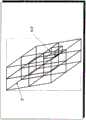
图15示出了限定示例性场景的八叉树立方体结构的高级八叉树立方体;FIG. 15 illustrates a high-level octopus structure defining the octet structure of an exemplary scene;
图16示出了穿过图15的八叉树立方体结构的切片,该切片示出了低级子八分体的产生;Fig. 16 shows a slice through the octantal building block structure of Fig. 15 showing the generation of low-level sub-octands;
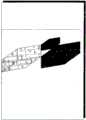
图17描绘了根据本发明实施例进行渲染的简单三维(3D)场景;Figure 17 depicts a simple three-dimensional (3D) scene rendered in accordance with an embodiment of the present invention;
图18描绘了图17的场景所对应的细分八叉树立方体;Figure 18 depicts a subdivided octagonal cube corresponding to the scene of Figure 17;
图19是图18的八叉树立方体所对应的八叉树数据结构的节点图;Fig. 19 is the node diagram of the octree data structure corresponding to the octet building cube of Fig. 18;
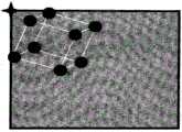
图20示出了图18的八叉树立方体的最高级立方体的3D到2D正交投影;Figure 20 shows a 3D to 2D orthographic projection of the superlative cube of the octagonal cube of Figure 18;
图21示出了图18的立方体的正交投影;Figure 21 shows an orthographic projection of the cube of Figure 18;
图22用于示出在不依赖3D到2D投影的情况下如何使用2D到2D操作根据限定高级立方体的投影的顶点来推出八分体的子立方体的投影;Figure 22 is used to illustrate how, without relying on a 3D-to-2D projection, a 2D-to-2D operation is used to deduce the projection of the sub-cubes of the octant from the vertices that define the projection of the advanced cube;
图23描述了对图17场景的渲染;Figure 23 depicts rendering of the scene of Figure 17;
图24示出了在正交模式下用于计算立方体2D投影顶点的替代性方法;Figure 24 shows an alternative method for computing cube 2D projected vertices in orthographic mode;
图25示出了如何将立方体2D投影的顶点计算为距显示屏的原点偏移;以及Figure 25 shows how the vertices of the cube 2D projection are calculated as offsets from the origin of the display screen; and
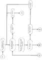
图26至28包含根据本发明优选实施例所述的方法的流程图。26 to 28 contain flowcharts of methods according to preferred embodiments of the present invention.
具体实施方式Detailed ways
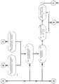
现在参考图1,其示出了用于实施根据本发明实施例所述的方法的示例性计算机系统1,下面将描述该示例性计算机系统1。Referring now to FIG. 1, there is shown an
可以理解的是,计算机系统1包括用于实施所述方法的、示例性的基于电子处理器的系统。然而,该方法也可轻易通过其他基于电子处理器的系统来实施。所述系统可包括但不限于:游戏控制台、平板、膝上和上网本型计算设备、蜂窝智能电话和医疗成像设备。It will be appreciated that the
计算机系统1包括主板3,主板3包括用于供电和联接到至少一个板载处理器5的电路。所述至少一个板载处理器可包括两个或更多个分立的处理器或具有多个处理核的处理器。The
作为非限定性示例,在用于玩计算机游戏的个人计算机中正流行的微处理器为Intel公司制造的i5或i7处理器组中的一种。As a non-limiting example, a microprocessor that is popular in personal computers for playing computer games is one of the i5 or i7 processor groups manufactured by Intel Corporation.
主板3用作微处理器5与次级存储器7之间的接口。次级存储器7可包括一个或多个光驱动器、磁驱动器或固态驱动器。次级存储器9存储用于操作系统9的指令。主板3还与随机访问存储器11和只读存储器(ROM)13通信。ROM 13通常存储用于基本输入输出系统(Basic Input Output System,BIOS)的指令,而微处理器5在启动时访问BIOS并且BIOS将微处理器5准备好用于载入操作系统9。The
主板3也与图形处理器单元(Graphics Processor Unit,GPU)15相连接。可以理解的是,在某些系统中,图形处理器单元15被集成在主板3中。The
主板3通常包括通信适配器,例如LAN适配器或调制解调器,使得计算机系统1与诸如因特网的计算机网络进行数据通信。The
计算机系统1的用户借助于键盘19、鼠标21和显示器17与计算机系统1交互。A user of
系统1的用户可操作操作系统9以载入计算机绘图相关的软件产品29。计算机绘图相关的软件产品29被提供为承载在诸如光盘27的计算机可读介质上的有形指令。或者,也可经由端口23进行下载。A user of the
计算机绘图相关的软件产品29包括数据结构,该数据结构存储限定各种场景(例如,游戏)的数据。Computer graphics related
软件产品29也包括用于微处理器5以及可能用于GPU 15的指令,以响应于经由诸如键盘19和鼠标21的操作者控制器从用户处接收的输入来操纵场景数据。
可以认识到的是,存在可用来存储场景数据的多种计算机数据结构。在本发明的优选实施例中,使用八叉树数据结构,尽管该数据结构是优选的,但是也可使用其他类型的数据结构,例如,二叉空间分区(BSP)树。It will be appreciated that there are a variety of computer data structures that may be used to store scene data. In a preferred embodiment of the present invention, an octree data structure is used, although this data structure is preferred, other types of data structures may also be used, such as binary space partition (BSP) trees.
不管使用哪种数据结构来存储场景的位置数据,都需要将数据从3D变换为2D以在显示设备17上显示。Regardless of which data structure is used to store the location data for the scene, the data needs to be transformed from 3D to 2D for display on
3D和2D图形的主要差异之一为由于距视点的距离而导致的透视和尺寸减小的概念。在图2中,对象根据其距视点的距离而变小。对该距离的计算为与3D图形相关联的3D到2D计算显著增加了更多的工作。One of the main differences between 3D and 2D graphics is the concept of perspective and size reduction due to distance from the viewpoint. In Figure 2, objects get smaller according to their distance from the viewpoint. Computation of this distance adds significantly more work to the 3D-to-2D computation associated with 3D graphics.
现在参考图3,其描述了用于在计算机系统1的显示器17上进行渲染的线框立方体31。显示器可以是任何合适的类型。例如,阴极射线管(CRT)、液晶显示器(LCD)或等离子显示器为显示器17可使用的显示技术的非限定性示例。针对立方体31的顶点或边缘数据存储在如前所述计算机系统的合适的数据结构中。Referring now to FIG. 3, a
图4代表了以侧视图示出的立方体31的2D单点投影在显示屏35上的视图。FIG. 4 represents a view of a 2D single point projection of the
从立方体31的顶点到相机点33的多束光线被示为穿过屏幕35以表示该立方体的3D顶点和边缘模型在包括屏幕35的2D观察面上的变换。该变换(或者也可称为“投影”)使用计算机绘图领域熟知的标准3D到2D透视投影来实现,所述标准3D到2D透视投影的解释参见以下书籍,例如:Computer Graphics Principles and Practice by Foley,van Dam,Feiner&Hughes 2nd Edition published 1990 by Addison-Wesley(ISBN 0-201-12110-7)(计算机绘图原理与实践(第二版),Foley,van Dam,Feiner&Hughes,1990年由Addison-Wesley出版(ISBN 0-201-12110-7)),其全部内容通过引用合并到本申请中。Multiple rays from the vertices of
如前面所评论的,透视变换是计算密集型,因为其涉及三角计算。As commented before, perspective transformation is computationally intensive because it involves trigonometry.
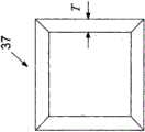
图5描绘了从相机点33所看到的立方体31的视图37。实际上,这是立方体31在观察平面35上的单点2D透视投影。为了在视觉上使立方体看起来为3D,该立方体的背面显示为明显地小于正面。FIG. 5 depicts a
应当注意到的是,立方体31的投影37中背面和正面的投影间隔一距离T。It should be noted that the
图7描绘了立方体中存在的对象。对象表现出尺寸上的差异,因为他们位于立方体的前部和后部。Figure 7 depicts the objects present in the cube. Objects exhibit differences in size as they are located at the front and back of the cube.
在诸如图1中的系统1的计算机绘图系统的情况下,屏幕35通常将包括显示监视器或其他显示设备,例如图1中的显示器17,包括图6所示的像素网格39。In the case of a computer graphics system such as
图8为叠印在像素网格39上立方体31的投影37的放大图。构成网格的像素具有所示出的假想宽度和高度p。FIG. 8 is an enlarged view of the
为了借助于像素网格39表示投影37,投影37的线所落入的那些像素被设置为对比色(即黑色,如本示例中所示)。所产生的像素图像如图9中所示。In order to represent the
应当指出的是,由于立方体31的投影37的背面和正面的距离T大于三个相邻像素的宽度,所以图9中的相应像素图像使得背面和正面能够相互区别。It should be noted that since the distance T between the back and front of the
图10与图4基本相似,不同之处在于前者表示从相机点33观察的较小3D立方体41(以平面图示出)在显示屏35上的投影。由于所使用的焦距远大于图4中的焦距,所以存在以间隙43表示的线性尺度上的非连续性。在图10中,平行光线45a、45b表示立方体41在显示屏35上的正交投影,而会聚光线对47a、47b表示透视投影。FIG. 10 is substantially similar to FIG. 4 , except that the former represents a projection of a smaller 3D cube 41 (shown in plan view) on
应当指出的是,由于立方体41的较小尺寸以及透视投影中所使用的较长焦距,所以正交投影的光线45a和45b以及与透视投影相关联的光线对47a和47b在显示屏35处被小于像素宽度p的距离所分开。It should be noted that due to the smaller size of the
图11是叠印在显示屏35的像素网格39上的立方体41关于相机点33的透视投影。FIG. 11 is a perspective projection of the
相似地,图12是叠印在显示屏35的像素网格39上的立方体41关于相机点33的正交投影。Similarly, FIG. 12 is an orthographic projection of the
应当指出的是,图11的透视投影与图12的正交投影覆盖相同的像素。因此,对于图13和图14中所示的每个投影,在显示屏35的像素网格39上生成并且由(例如)游戏玩家的计算机系统用户所看到的实际图像是相同的。该投影显著小于图9中所示的投影。由于该投影的尺寸小,背面与正面之间的差异是无法观察到的,所以在该图中,立方体看起来为正方形。It should be noted that the perspective projection of FIG. 11 covers the same pixels as the orthographic projection of FIG. 12 . Thus, for each of the projections shown in Figures 13 and 14, the actual image generated on the
如果在该立方体中存在对象,则不会因为对象在立方体的正面或背面而看起来较小或较大。If an object is present in the cube, it will not appear smaller or larger because the object is on the front or back of the cube.
从技术上讲,在正面与背面之间总是存在差异,但是,由于计算机监视器为像素网格,当差异小于一个像素的尺寸时,所述差异会因太小而不存在。正常情况下,3D计算使用透视,但是,由于正面和背面之间不存在尺寸差异,所以使用不将透视考虑在内的不同计算。Technically, there is always a difference between the front and the back, but since computer monitors are a grid of pixels, when the difference is less than the size of a pixel, the difference is too small to exist. Normally, 3D calculations use perspective, however, since there is no dimensional difference between the front and back, a different calculation is used that does not take perspective into account.
尽管使用单点投影得到上述例证,但是发明人发现相应的结果也适用于两点和三点投影。Although the above illustration was obtained using a single-point projection, the inventors have found that the corresponding results are also applicable to two-point and three-point projections.
从以上讨论中可认识到,取决于待表示的3D对象的尺寸以及诸如该对象在观察平面之后的距离和所用焦距之类的参数,在使用正交投影生成对象的视图与使用透视投影生成对象的视图之间可不存在可观察到的差异。但是,透视投影比正交投影的计算开销大得多,即,对于透视投影,计算数量较高。It can be appreciated from the above discussion that, depending on the size of the 3D object to be represented and parameters such as the distance of the object behind the viewing plane and the focal length used, the difference between generating a view of an object using orthographic projection and generating an object using perspective projection There may be no observable differences between the views. However, perspective projection is much more computationally expensive than orthographic projection, i.e., for perspective projection, the number of computations is higher.
此外,线框立方体31和41可当作边界框。因此,如果像框41那样,边界框可使用正交投影进行渲染,则场景中落入该边界框内的任何对象也都可使用正交投影进行渲染。Furthermore, the
因此,发明人发现:对于通过透视投影进行渲染与通过正交投影进行渲染出现可觉察到的差异场景中的对象,可使用透视投影激活电子显示设备的像素来渲染该场景,而对于其余的对象,可使用正交投影激活像素来渲染该场景,从而生成总体上看起来使用透视变换进行真实渲染的场景。Accordingly, the inventors have discovered that for objects in a scene where there is a perceptible difference between rendering by perspective projection and rendering by orthographic projection, the scene can be rendered using perspective projection to activate the pixels of the electronic display device, while for the remaining objects , the scene can be rendered using an orthographic projection activation pixel, resulting in a scene that generally looks realistically rendered using perspective transforms.
此外,如所进行的简单说明所示,在本发明的方法的优选实施例中,可基于整个母八分体立方体的2D投影来生成由八叉树建模的场景的八分体的2D投影,而无需将每个八分体单独地从3D空间投影到2D空间。Furthermore, as shown in a brief description, in a preferred embodiment of the method of the present invention, a 2D projection of an octant of a scene modeled by an octree can be generated based on a 2D projection of the entire parent octant cube , without projecting each octant individually from 3D space to 2D space.
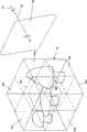
图15描述了包括三个对象的场景,该三个对象为叠印在整个八叉树立方体43内的蘑菇的形式。八叉树立方体在图1所示的计算机系统的内存中被存储为数据结构。为了清楚起见,图15中仅可见以实线示出的八叉树的整个母立方体43,以及该母立方体43的以虚线示出的第一组8个子八分体45a,……,45h。然而,从计算机绘图技术中可知,八叉树子立方体围绕场景中对象的部分继续进行细分,场景中对象的部分被弯曲至预定的分辨率极限。如图16中所示,其中包括穿过图15中的八叉树的切片,在该切片中可看到其他三个等级的八分体49、51和53。FIG. 15 depicts a scene that includes three objects in the form of mushrooms superimposed within the entire
将参考图17至图23描述根据本发明优选实施例所述的方法。The method according to the preferred embodiment of the present invention will be described with reference to FIGS. 17 to 23 .
图17描绘了包括三个呈3D立方体55、57和59形式的非常简单的对象的场景。为了进行解释,需要操作图1的计算机系统沿图17中所示的视角63显示图17场景的2D表示。FIG. 17 depicts a scene comprising three very simple objects in the form of
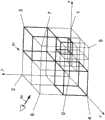
图18描绘了被细分为八分体用于对图15中的场景进行建模的整个八叉树立方体61。为了进行解释,假设八叉树61的整体尺寸使得在施加了正交投影而不是透视投影的情况下将不会觉察到明显的差异,正如结合图10中的立方体41所解释的那样。FIG. 18 depicts the entire
整个八叉树立方体61已经被细分成编号为0至7的8个第一等级子立方体。立方体5已经进一步被细分为8个第二等级子立方体。第一等级子立方体3和4以及第一等级子立方体5的第二等级子立方体3对图17中所示的场景的立方体55、57和59进行建模。The entire
八叉树立方体61在图1的计算机系统存储器中,以包括图19中所示八叉树的数据结构的方式进行存储。The
为了显示图17中的场景,按照相对于视角63从前到后的顺序读取(即遍历)八叉树的节点。To display the scene in FIG. 17, the nodes of the octree are read (ie, traversed) in front-to-back order relative to view 63.
与遮挡剔除相关联的主要运算为求得边界框的尺寸。在基于八叉树的系统中,这一般包括采集环绕立方体(encompassing cube)的8个值,将这些值从3D自然空间(worldspace)转化到3D屏幕空间,并且对这些值进行排序以确定水平及垂直最小值和最大值。在基于透视的系统中,这是相当大量的工作,因为一般将针对每个框进行计算。如前面所提及的,根据本发明的优选实施例所述的方法利用了将自然/对象分解为较小正交分区的概念。使用这些分区以求得边界框尺寸可被二等分水平和垂直边缘所取代,因为在处理八叉树数据时正交分区边界框正好是其母边界框大小的四分之一。The main operation associated with occlusion culling is to obtain the size of the bounding box. In octree-based systems, this typically involves taking 8 values around the encompassing cube, transforming these values from 3D worldspace to 3D screen space, and sorting these values to determine levels and Vertical minimum and maximum values. In a perspective-based system, this is quite a lot of work, as the calculations will generally be done for each box. As mentioned previously, the method according to the preferred embodiment of the present invention utilizes the concept of decomposing nature/objects into smaller orthogonal partitions. Using these partitions to find the bounding box size can be replaced by bisecting the horizontal and vertical edges, since the orthogonal partition bounding box is exactly one-fourth the size of its parent bounding box when processing octree data.
从计算机绘图技术中可知,可从8个不同观察区域观察八叉树,针对前到后观察,遍历八叉树的顺序表可根据视角所落入的区域进行制定。对于图16中所示的视点位于区域+x、+y、+z中的情形,针对前到后观察,遍历八叉树的顺序为“7、6、5、3、4、2、1、0”。It can be known from computer graphics technology that the octree can be observed from 8 different observation areas, and for front-to-back observation, the sequence table for traversing the octree can be formulated according to the area in which the viewing angle falls. For the situation shown in Figure 16 where the viewpoints are located in the regions +x, +y, +z, for front-to-back observation, the order of traversing the octree is "7, 6, 5, 3, 4, 2, 1, 0".
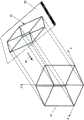
现在参考图20,由8个3D顶点坐标P0(x0,y0,z0),…,P7(x7,y7,z7)所限定的整个八叉树立方体61被正交地投影到视角63处的期望观察平面65,从而生成包括有8个2D顶点P(x0,y0),…,P(x7,y7)的立方体的2D投影67。参考图21,限定2D投影的顶点的8个2D顶点P(x0,y0),…,P(x7,y7)可被称为“形式图案”,因为其限定了八叉树投影的形状。此外,由于投影是正交的,所以当被按比例缩小时,也可以限定子八分体的投影的形状,而在使用透视投影的情况下却不是这样的。Referring now to FIG. 20, the entire
在图21的示图中,顶点被示为被边缘互连,但是这些边缘在对图17的场景的最终渲染中将不会显现。形式图案(Form Pattern,FP)顶点P0(x0,y0),…,P7(x7,y7)按照与八叉树的观察顺序相同的顺序被存储在阵列中,即,FP阵列=[P7、P6、P5、P3、P4、P2、P1、P0]。In the diagram of FIG. 21 , the vertices are shown as being interconnected by edges, but these edges will not appear in the final rendering of the scene of FIG. 17 . Form Pattern (FP) vertices P0(x0,y0),...,P7(x7 ,y7) are stored in the array in the same order as the viewing order of the octree, ie, FP array=[P7, P6 , P5 , P3 , P4 , P2 , P1 , P0 ].
然后按照从前到后的顺序读取图19的八叉树,对于图18中所示的视点,该顺序为7、6、5、3、4、2、1、0。The octree of Figure 19 is then read in front-to-back order, which for the viewpoint shown in Figure 18 is 7, 6, 5, 3, 4, 2, 1, 0.
由于节点7为空,所以不采取任何动作。Since
由于节点6为空,所以不采取任何动作。Since
由于节点5指向子节点,所以程序深入到下一等级。Since
在下一等级中:In the next level:
由于节点7为空,所以不采取任何动作。Since
由于节点6为空,所以不采取任何动作。Since
由于节点5为空,所以不采取任何动作。Since
由于节点3为叶节点,所以对于子节点5的子节点3,调用叶节点(Leaf Node)子例程。叶节点子例程将在下文中描述。Since
由于节点4为空,所以不采取任何动作。Since
由于节点2为空,所以不采取任何动作。Since
由于节点1为空,所以不采取任何动作。Since
由于节点0为空,所以不采取任何动作,然后程序跳高一个等级。Since
由于节点3为叶节点,所以对于子节点3,调用叶节点子例程。Since
由于节点4为叶节点,所以对于子节点4,调用叶节点子例程。Since
由于节点2为空,所以不采取任何动作。Since
由于节点1为空,所以不采取任何动作。Since
由于节点0为空,所以不采取任何动作。Since
叶节点子例程向形式图案阵列传送边界框的最小点(MinPoint)和最大点(MaxPoint)以及叶节点信息。The leaf node subroutine transfers the minimum point (MinPoint) and maximum point (MaxPoint) of the bounding box and leaf node information to the formal pattern array.
八叉树立方体61的投影67的边界框的左上角(在当前情况下与顶点(x0,y0)重合)被用作8个顶点(x0,y0),…,(x7,y7)的原点。The upper left corner of the bounding box of the
然后,叶节点子例程在8个顶点(x0,y0),…,(x7,y7)上运算以将其二等分从而生成图19中所示的8个点(x0,y0)2,…,(x7,y7)2。8个顶点(x0,y0)2,…,(x7,y7)2将图18的八叉树立方体的八分体2的2D投影限定为如图22中所示的2'。应当指出的是,该投影通过对限定了整个八叉树八分体立方体的2D投影顶点的点进行划分而得到。并不需要将八分体2的3D顶点投影到观察平面中。因此,这8个点(x0,y0)2,…,(x7,y7)2为距边界框69的最小值的偏移。相对于边界框69的最小值,移位运算用于二等分8个顶点(x0,y0),…,(x7,y7)。新的点(x0,y0)2,…,(x7,y7)2中的每个点被再次二等分以针对下一低等级的每个八分体生成另外的8个子点,例如(x0,y,0)3,…,(x7,y7)3。例如,如图22中的子八分体立方体投影5-3’所示的那样。The leaf node subroutine then operates on the 8 vertices (x0,y0),...,(x7,y7) to bisect them to generate the 8 points (x0,y0)2 shown in Figure 19, . 2' shown. It should be noted that the projection is obtained by dividing the points that define the vertices of the 2D projection of the entire octree octant cube. It is not necessary to project the 3D vertices of
在八叉树表明子八分体是叶节点的情况下,叶节点如图23中那样被加上阴影以生成对原本在图17中所描绘的场景的渲染。倘若对象(例如,图23的立方体)的尺寸足够小,则出于之前参考图1至图13所讨论的原因,使用正交投影进行渲染或者使用透视投影变换进行渲染的立方体之间将不会存在明显的差异。Where the octree indicates that the sub-octets are leaf nodes, the leaf nodes are shaded as in FIG. 23 to generate a rendering of the scene originally depicted in FIG. 17 . If the size of the object (eg, the cube of Figure 23) is small enough, there will be no interaction between cubes rendered using an orthographic projection or using a perspective projection transformation for the reasons discussed earlier with reference to Figures 1 to 13. There are clear differences.
如果形式图案方法不与具有终端分支的八叉树数据相关,则该方法可渲染浮点的实心立方体。通过将形式图案方法与八叉树数据相关联以及在分支为空时展开图案,形式图案方法实际上可使用类比将形式图案切开,就像形式图案是灰泥一样。最终对象与通过传统技术使用带有3D到2D算法的立体像素所产生的对象具有相同的特性和形式,但是就处理能力而言,形式图案技术使用了小部分时间和运算。If the formal pattern method is not associated with octree data with terminal branches, this method renders a solid cube of floating point. By associating the formal pattern method with the octree data and unfolding the pattern when the branches are empty, the formal pattern method can actually use an analogy to slice the formal pattern as if the formal pattern were stucco. The final object has the same characteristics and form as those produced by traditional techniques using voxels with 3D to 2D algorithms, but in terms of processing power, the formal patterning technique uses a fraction of the time and operations.
由2D正交投影点(x0,y0),…,(x7,y7)所限定的母立方体的投影形状可被称为“形式图案”,因为其不仅限定了最高级母八分体而且限定了降级子八分体的正交投影比例,即形式。可实施形式图案的多种变型。The projected shape of the parent cube defined by the 2D orthographic projected points (x0,y0),...,(x7,y7) can be called a "form pattern", since it defines not only the superlative parent octant but also the parent octant. The orthographic projection scale of the degraded sub-octant, i.e. the form. Numerous variations of form patterns can be implemented.
例如,顶点通常被存储为8个“X”值和8个“Y”值,例如上文所述的(x0,y0),…,(x7,y7)。然而,也有可能收集4个“X”值和4个“Y”值,并且通过将所收集的值相对于中心点偏移来生成其余的值,该中心点通过以下方式生成:将运算所在的立方体的三维中心点进行二维投影或者使用前述边界框(例如,图21中的框69)的2D中心点。只要收集到这些偏移,某些点可以通过对这些值的符号取反而生成。通过合适地收集一半的所讨论角值(cornervalues),其余的值可通过使用该方法而生成。由符号取反产生点的方法仅对如图24中所示的被正交投影的立方体或棱柱体是精确的。For example, vertices are typically stored as 8 "X" values and 8 "Y" values, such as (x0,y0),...,(x7,y7) as described above. However, it is also possible to collect 4 "X" values and 4 "Y" values, and generate the remaining values by offsetting the collected values with respect to a center point generated by placing the operation on The 3D center point of the cube is projected in 2D or using the 2D center point of the aforementioned bounding box (eg,
形式图案通常为相对于边界框19的4个角中的一个的偏移。或者,形式图案也可以是距边界框内或边界框范围之外的任一点的偏移,也可以没有偏移,而将其在当前屏幕像素上所具有的不变值作为形式图案的值。然而,对边界框4个角之一的使用被认为有助于理解,并且使得左上角(在图21中被表示为“最小值(Min)”)与将屏幕的左上角看作在图25中所示的位置(0,0)的实践相一致。The form pattern is typically an offset relative to one of the 4 corners of the
渲染3D图形最处理密集的部分之一为将点从3D空间转化到2D屏幕。正常情况下,该处理包括相当多的数学运算。二等分形式图案以及将这些二等分点添加到母形式图案点的形式图案点上产生了与正常的3D到2D转化相同的输出。One of the most processing-intensive parts of rendering 3D graphics is converting points from 3D space to a 2D screen. Normally, this process involves quite a bit of math. Bisecting the form pattern and adding these bisect points to the form pattern points of the parent form pattern point produces the same output as a normal 3D to 2D conversion.
在优选实施例中,计算形式图案不使用相乘、除法或者多个复杂运算。这将在这个系统中用移位(BIT SHIFT)和相加(ADD)来替代。在基于3D图形透视的正常情况下,该方法不起作用,但是,如果待渲染对象被分为如上所述的正交子部分,则系统可利用该非正常图案。In a preferred embodiment, computing the formal pattern does not use multiplication, division, or multiple complex operations. This will be replaced by BIT SHIFT and ADD in this system. In normal cases based on 3D graphics perspective, this method does not work, but if the object to be rendered is divided into orthogonal subsections as described above, the system can take advantage of this non-normal pattern.
现在参考图26至图28,根据优选实施例所述的用于处理八叉树数据结构的方法以流程图的形式给出,所述八叉树数据结构含有对用于渲染的场景进行建模的数据。该方法可被编码为有形的计算机可读指令(例如承载在图1中的光盘27上)以使得其组成计算机软件产品29用于通过计算机系统1进行处理。Referring now to Figures 26-28, a method for processing an octree data structure according to a preferred embodiment is presented in the form of a flow diagram, the octree data structure containing modeling a scene for rendering The data. The method may be encoded as tangible computer readable instructions (eg carried on
现在将讨论图26至28的流程图中的每个流程框处所进行的各种处理。The various processing performed at each block in the flowcharts of FIGS. 26-28 will now be discussed.
在流程框83处,掩模缓存被清零。掩模缓存是一系列的标识位,显示缓存中的每个像素对应于一个标识位,标识位表明像素是否写入该位置。由于算法所提供的从前到后的顺序,每个像素只需要写入一次。当使节点的2D边界框重叠的所有像素都已被写入时,掩模缓存用于忽略该节点及其所有子节点。At block 83, the mask buffer is cleared. The mask buffer is a series of flags, each pixel in the display buffer corresponds to a flag that indicates whether the pixel is written to that location. Because of the front-to-back order provided by the algorithm, each pixel only needs to be written once. When all pixels that overlap a node's 2D bounding box have been written, the mask cache is used to ignore the node and all of its children.
在流程框84处,每个节点可具有0至8个子节点;只要节点上出现的所有子节点都被处理,则该节点被移出堆栈并且不再被考虑。At block 84, each node may have 0 to 8 child nodes; as long as all child nodes present on a node are processed, the node is removed from the stack and is no longer considered.
在流程框85处,对于递归实施方式,通过简单地返回函数来将最前端的节点移出堆栈。在迭代实施方式中,堆栈的尺寸被减小1。At block 85, for a recursive implementation, the frontmost node is moved off the stack by simply returning the function. In an iterative implementation, the size of the stack is reduced by one.
在流程框86处,当堆栈上不存在节点时,整个模型被处理完毕。At block 86, when there are no nodes on the stack, the entire model is processed.
在流程框87处,按照从前到后的顺序处理子节点,每个子节点被标记为已处理以确定何时可忽略节点(参见流程框84)。At block 87, the child nodes are processed in front-to-back order, each marked as processed to determine when a node can be ignored (see block 84).
在流程框88处,母节点被标记为正交模式,只要该母节点或该母节点的任何一个母节点满足针对正交模式的标准,参见流程框101和102。At block 88, a parent node is marked as orthogonal mode, as long as the parent node or any of the parent nodes satisfy the criteria for orthogonal mode, see
在流程框89处,与附近的观察平面相交的节点必须被细分以避免数学上的不精确。At block 89, nodes that intersect a nearby viewing plane must be subdivided to avoid mathematical imprecision.
在流程框90处,当前节点被推入堆栈,从而确保其子节点(如果存在的话)接下来可被处理。At block 90, the current node is pushed onto the stack, ensuring that its children (if any) can be processed next.
在流程框91处,在正交模式中,通过以下方式计算2D边界框:针对自生成正交数据以来的各个等级的家系(ancestry),获得保存在正交缓存数据中的2D边界框的尺寸并且将其除以2。也就是说,满足正交模式标准(参见流程框101)的节点的子节点将具有正好等于存储在正交数据缓存中的边界框尺寸一半的边界框尺寸。孙节点将具有正好四分之一的边界框尺寸,以此类推。在实践中,创建正交缓存数据时堆栈的尺寸可被存储在正交缓存数据中,并且从给出要被2除以的次数的堆栈尺寸中减去。在得到该值的情况下,使用二进制移位运算实现了除法,这比遗传除法要快得多。在得到所计算的边界框尺寸的情况下,通过以下方式来计算偏移:基于子节点数量选择框偏移值,针对各个等级的家系通过与尺寸完全相同的方式将框偏移值除以2,以及所得的商加到存储在正交缓存数据中的边界框位置上。At block 91, in ortho mode, a 2D bounding box is calculated by obtaining the dimensions of the 2D bounding box stored in the ortho cache data for each level of ancestry since the ortho data was generated and divide it by 2. That is, children of a node that satisfy the orthogonal mode criteria (see block 101) will have a bounding box size that is exactly half the size of the bounding box stored in the orthogonal data cache. The grandchild nodes will have exactly one quarter the size of the bounding box, and so on. In practice, the size of the stack when the quadrature cache data is created may be stored in the quadrature cache data and subtracted from the stack size giving the number of times to divide by 2. Given this value, the division is implemented using a binary shift operation, which is much faster than genetic division. Given the calculated bounding box size, the offset is calculated by choosing a box offset value based on the number of child nodes, dividing the box offset value by 2 for each level of pedigree in exactly the same way as the size , and the resulting quotient is added to the bounding box location stored in the orthogonal buffer data.
在流程框92处,在透视模式中,通过使用标准方式在当前节点的3D边界框的8个角点上进行到屏幕空间的全透视变换来计算2D边界框。通常,这是4x4矩阵与3D矢量相乘所得到的4D矢量(x,y,z,w),其中w分量被用作除数以进行最后的透视变换。应当认识到的是,根据本发明优选实施例所述的系统被设计为尽量避免该步骤。At process block 92, in perspective mode, a 2D bounding box is computed by performing a full perspective transformation to screen space on the 8 corners of the current node's 3D bounding box using standard means. Typically, this is a 4D vector (x,y,z,w) resulting from multiplying a 4x4 matrix by a 3D vector, where the w component is used as a divisor for the final perspective transformation. It should be appreciated that the system according to the preferred embodiment of the present invention is designed to avoid this step as much as possible.
在流程框93处,只要计算出2D边界框,测试其是否与任一屏幕边缘重叠,如果重叠,则相应地调整坐标以仅反映出框中与显示缓存重叠的部分。如果边界框完全在显示缓存之外,则不再考虑该节点并且控制流程至流程框84以处理该节点的其余子节点。At block 93, once the 2D bounding box is calculated, it is tested whether it overlaps any of the screen edges, and if so, the coordinates are adjusted accordingly to reflect only the portion of the box that overlaps the display buffer. If the bounding box is completely outside the display cache, the node is disregarded and control flows to block 84 to process the remaining child nodes of the node.
在流程框94处,由于从前到后的绘制顺序(drawing order),只要任一节点的边界框内的所有像素都已被写入,则该节点被封闭并且不再被考虑。通过测试掩模缓存中对应于边界框区域的每个标识位来实现该测试,如果所有的像素都被标记为已写入,则可丢弃该节点并且控制流程至流程框84。At block 94, as long as all pixels within the bounding box of any node have been written, due to the front-to-back drawing order, the node is closed and no longer considered. This is accomplished by testing each flag bit in the mask buffer corresponding to the bounding box region, if all pixels are marked as written, the node can be discarded and control flows to block 84 .
在流程框95处,如果节点在处理过程中此刻不具有子节点,则提取(drawn)该节点(参见流程框97)。At block 95, if the node has no child nodes at this point in the process, the node is drawn (see block 97).
在流程框96处,如果边界框的尺寸等于或小于阈值(比如1个像素),则提取该节点。这主要是因为一个像素尺寸以下的进一步细分是不必要的。At block 96, if the size of the bounding box is equal to or smaller than a threshold (eg, 1 pixel), the node is extracted. This is mainly because further subdivisions below one pixel size are unnecessary.
在流程框97处,为了提取(draw)节点,在掩模缓存中对经固定的2D边界框所对应的每个像素进行测试,并且当像素未被写入时,彩色缓存中相应的像素被设置为该节点的颜色并且设定掩模缓存。另外,此刻可写入其他缓存以记录信息,例如深度值和/或正常值。At block 97, to draw the node, each pixel corresponding to the fixed 2D bounding box is tested in the mask buffer, and when the pixel is not written, the corresponding pixel in the color buffer is Set to the color of this node and set the mask cache. Additionally, other buffers may be written to record information such as depth values and/or normal values at this time.
在流程框98处,当前节点被推入堆栈,从而确保其子节点接下来可被处理。At
在流程框99处,只要节点满足针对正交模式的标准,该节点的所有子节点也隐含地为正交的,所以此刻标识位和正交缓存数据被复制以将正交模式传递到子节点。At block 99, as long as a node satisfies the criteria for the orthogonal mode, all of the node's children are also implicitly orthogonal, so now the flag bits and the orthogonal buffer data are copied to pass the orthogonal mode to the children node.
在流程框100处,在节点中设置正交模式标识位以表明其家系中任一节点是否满足正交模式标准。At
在流程框101处,测试针对正交模式的标准。如已结合图3至图15所讨论的,该标准定性为:当使用透视将框投影到屏幕空间时,该框的背面看起来比该框的正面小的量(由于透视效应)小于1个像素,因而在光栅化时不会被觉察到。有很多方式对此进行测试,但是由于通过将矢量除以w(如结合流程框92所讨论的)施加了透视效应,所以便捷而简单的测试方式为测试框前部的经变换点与框后部的经变换点之间的w值的比率。实际的阈值比率随焦距和显示缓存的尺寸而变化,所以当这些参数中的任一个变化时,必须重新计算该阈值比率。At block 101, the criteria for orthogonal modes are tested. As already discussed in connection with Figures 3 to 15, this criterion characterizes that when a box is projected into screen space using perspective, the back of the box appears smaller than the front of the box by an amount (due to perspective effects) less than 1 Pixels, so they won't be noticed when rasterizing. There are many ways to test this, but since perspective effects are applied by dividing the vector by w (as discussed in connection with flow block 92), a convenient and simple way to test is to test the transformed points in front of the box and the back of the box. The ratio of w values between the transformed points of the part. The actual threshold ratio varies with focal length and the size of the display buffer, so when any of these parameters change, the threshold ratio must be recalculated.
因此,监视和执行正交模式包括两部分:Therefore, monitoring and enforcing the quadrature mode consists of two parts:
第一部分包括预计算最佳阈值(当显示尺寸或焦距(视场)变化时进行更新),第二部分包括在渲染的过程中应用该阈值。The first part consists of precomputing the optimal threshold (updated when the display size or focal length (field of view) changes) and the second part consists of applying the threshold during rendering.
如上所述,潜在的逻辑比较简单;想要知道的是何时经投影的前坐标与后坐标间隔小于1.0像素(或者类似的公差值)。As mentioned above, the underlying logic is relatively simple; what you want to know is when the projected front and back coordinates are separated by less than 1.0 pixels (or a similar tolerance value).
虽然可能存在直接计算该值的方式,但是当前使用二进制搜索。标准的二进制搜索在近Z(nearZ)与远Z(farZ)之间进行,从而将近点(nearPoint)=(1,1,1)与远点(farPoint)=(1,1,-1)的点对进行变换,增加(0,0,midZ),其中中Z(midZ)就是近Z与远Z之间的中间值。Binary search is currently used, although there may be a way to compute this value directly. The standard binary search is performed between near Z (nearZ) and far Z (farZ), so that the near point (nearPoint) = (1, 1, 1) and the far point (farPoint) = (1, 1, -1) Transform the point pair and add (0,0,midZ), where Z(midZ) is the middle value between the near Z and the far Z.
如果经投影的X,Y的变化小于像素阈值,则定位阈值点。If the projected X,Y change is less than the pixel threshold, then locate the threshold point.
使用来自二进制搜索的经变换点(即为X,Y,Z,W),则可计算出固定W比率=近W/远W。Using the transformed points (ie, X, Y, Z, W) from the binary search, a fixed W ratio = near W/far W can be calculated.
然后,在透视模式的渲染中,计算出8个经变换的框点(每个为X,Y,Z,W)。Then, in perspective mode rendering, 8 transformed box points (each X, Y, Z, W) are calculated.
然后,通过计算X,Y,W Min和Max来确定边界框。(注意此处的W)Then, the bounding box is determined by computing X, Y, W Min and Max. (note the W here)
然后,当前W比率被计算为curW比率=minW/maxW。Then, the current W ratio is calculated as curW ratio=minW/maxW.
如果(当前W比率>=固定W比率),则进入正交模式。If (current W ratio >= fixed W ratio), enter quadrature mode.
应当认识到的是,由于1/w通常被计算为透视变换的一部分,所以可能通过乘以倒数来代替除法,这是常见的浮点优化。It should be appreciated that since 1/w is usually computed as part of the perspective transform, it is possible to multiply by the reciprocal instead of dividing, which is a common floating point optimization.
还应当指出的是,该方法在某种程度上不同于将针对比如为24的像素阈值的x与y的变化(同样通过二进制搜索或试凑法进行计算)相比较的经典方法。It should also be noted that this method differs somewhat from the classical method of comparing changes in x and y (again computed by binary search or trial and error) for a pixel threshold such as 24.
上面所讨论的方法较优,因为其允许八叉树节点尽快进入正交模式而不管该节点相对于屏幕的取向如何。另外,旋转节点的边界框可以使阈值测试偏向40%(即sqrt(2)),从而延迟进入正交模式直到被进一步细分。The method discussed above is preferable because it allows an octree node to enter orthogonal mode as quickly as possible regardless of the orientation of the node relative to the screen. Additionally, rotating the node's bounding box can bias the threshold test by 40% (ie sqrt(2)), delaying entry into orthogonal mode until further subdivided.
应当理解的是,该方法也同样讲得通,因为尽管投影的效应在于形成较小尺寸的边界框,但是根本原因为x/w y/w,即w的相对比率会使透视缩短x、y的值。所以,测试w更加符合逻辑并且更加精确。It should be understood that this approach also makes sense, since although the effect of the projection is to form a smaller size bounding box, the root cause is x/w y/w, i.e. the relative ratio of w will shorten the perspective by x, y value. Therefore, the test w is more logical and more precise.
衡量标准的其他指标包括:屏幕空间中立方体一个边的长度,或者屏幕空间中包围立方体的球的直径。Other metrics for metrics include: the length of a side of the cube in screen space, or the diameter of the sphere that encloses the cube in screen space.
在流程框102处,正交缓存数据包括:节点的深度/八叉树向下的等级(由堆栈的当前长度表示)、该节点的2D边界框以及作为距2D边界框左上角的偏移的8个经变换屏幕空间点。At
总之,正交模式通过对八叉树数据结构的节点进行划分以及追踪包含立方体的内容的历程来在八叉树数据结构的节点上操作。正交模式过程可以绕开3D到2D变换并且(例如)通过递归地二等分2D点集(即表示较高等级八分体的投影的“形式图案”)而得到代表子八分体的投影的相应的点集来代替缩放。In summary, the Orthogonal mode operates on nodes of an octree data structure by dividing the nodes of the octree data structure and tracing the journeys that contain the contents of the cube. The orthogonal mode process can bypass the 3D-to-2D transformation and obtain projections representing sub-octets (for example) by recursively bisecting the set of 2D points (ie "form patterns" representing projections of higher-order octants) instead of scaling the corresponding point set.
由于仅对于透视投影与正交投影之间不存在显著差异的八分体,才进入正交模式,所以正如在流程的流程框88处所测试到的那样,通过该方式进行渲染场景的观察者将感觉该场景与完全使用透视变换进行渲染的场景一样。尽管通过正交模式进行渲染的每个子部分不具有内部透视,但是在这些子部分之间存在透视。因此,尽管子部分不会在靠近后部处变小,但是从内部而言,只要考虑到子部分与观察者的关系,整个子部分就会处于合适的尺寸。Since the orthographic mode is only entered for octants where there is no significant difference between the perspective projection and the orthographic projection, as tested at block 88 of the process, an observer rendering a scene this way will The scene feels the same as if it were rendered entirely with perspective transforms. Although each subsection rendered in orthographic mode does not have internal perspective, there is perspective between the subsections. So while the subsection doesn't get smaller near the rear, internally the whole subsection is at the right size considering its relationship to the viewer.
所有这些不同尺寸的子部分的组合产生具有透视效果的3D图像,该具有透视效果的3D图像与通过更数学运算密集的3D系统生成的图像在外观上具有相似性,但使用的运算却要少得多。The combination of all these different sized subsections produces a perspective 3D image that is similar in appearance to an image produced by a more mathematically intensive 3D system, but uses fewer operations much more.
根据相关法令,使用或多或少特定于结构或方法特征的语言对本发明进行了描述。术语“包括(comprises)”及其变型“包括(comprising)”和“包括(comprised of)”等在全文中以包含在内的意义使用并且不排除任何附加特征。应当理解的是,本发明并不限于所示出或所描述的具体特征,因为本发明中所描述的方法包括以优选的形式实施本发明。因此,适当范围内本领域技术人员所适当理解的所附权利要求的任何形式或改进,均视为本发明的保护范围。In accordance with the relevant statutes, the invention has been described using language more or less specific to structural or methodological features. The terms "comprises" and its variants "comprising" and "comprised of" and the like are used in an inclusive sense throughout and do not exclude any additional features. It is to be understood that this invention is not limited to the specific features shown or described, as the methods described in this invention include embodiments of the invention in preferred forms. Therefore, any form or improvement of the appended claims that are properly understood by those skilled in the art within an appropriate scope shall be regarded as the protection scope of the present invention.
在整个说明书和权利要求书中,除非上下文另有需要,否则术语“基本上”或“大约”将被理解为不对该术语所限定的值的范围加以限制。Throughout the specification and claims, unless the context requires otherwise, the terms "substantially" or "approximately" will be understood as not limiting the range of values defined by the term.
Claims (16)
Applications Claiming Priority (1)
| Application Number | Priority Date | Filing Date | Title |
|---|---|---|---|
| PCT/AU2012/001130WO2014043735A1 (en) | 2012-09-21 | 2012-09-21 | A computer graphics method for rendering three dimensional scenes |
Publications (2)
| Publication Number | Publication Date |
|---|---|
| CN104781852A CN104781852A (en) | 2015-07-15 |
| CN104781852Btrue CN104781852B (en) | 2020-09-15 |
Family
ID=50340437
Family Applications (1)
| Application Number | Title | Priority Date | Filing Date |
|---|---|---|---|
| CN201280076971.3AActiveCN104781852B (en) | 2012-09-21 | 2012-09-21 | Computer drawing method for rendering three-dimensional scene |
Country Status (7)
| Country | Link |
|---|---|
| US (1) | US9842425B2 (en) |
| EP (1) | EP2898480B1 (en) |
| JP (1) | JP6159807B2 (en) |
| CN (1) | CN104781852B (en) |
| AU (1) | AU2012390266B2 (en) |
| CA (1) | CA2885283C (en) |
| WO (1) | WO2014043735A1 (en) |
Families Citing this family (27)
| Publication number | Priority date | Publication date | Assignee | Title |
|---|---|---|---|---|
| US12008707B2 (en)* | 2013-02-14 | 2024-06-11 | David Todd Kaplan | Highly scalable cluster engine for hosting simulations of objects interacting within a space |
| US10521520B2 (en)* | 2013-02-14 | 2019-12-31 | Nocturnal Innovations LLC | Highly scalable cluster engine for hosting simulations of objects interacting within a space |
| EP3040945B1 (en)* | 2014-12-30 | 2019-06-19 | Dassault Systèmes | Creation of bounding boxes on a 3d modeled assembly |
| EP3295431A4 (en)* | 2015-05-11 | 2018-04-04 | Pointerra Technologies Pty Ltd | Method and system for computer graphics rendering |
| CN105488755B (en)* | 2015-11-25 | 2018-10-23 | 网易(杭州)网络有限公司 | A kind of method and device for realizing 3D performances in 2D game |
| CN105513118B (en)* | 2015-11-26 | 2018-07-10 | 北京像素软件科技股份有限公司 | A kind of rendering intent of voxelization gaming world |
| AU2017250112B2 (en)* | 2016-04-12 | 2020-09-17 | Quidient, Llc | Quotidian scene reconstruction engine |
| US10158834B2 (en)* | 2016-08-30 | 2018-12-18 | Hand Held Products, Inc. | Corrected projection perspective distortion |
| GB2566279B (en)* | 2017-09-06 | 2021-12-22 | Fovo Tech Limited | A method for generating and modifying images of a 3D scene |
| EP3467777A1 (en)* | 2017-10-06 | 2019-04-10 | Thomson Licensing | A method and apparatus for encoding/decoding the colors of a point cloud representing a 3d object |
| CN108043027B (en)* | 2017-11-27 | 2020-09-11 | 腾讯科技(上海)有限公司 | Storage medium, electronic device, game screen display method and device |
| EP3503037B1 (en)* | 2017-12-24 | 2025-08-13 | Dassault Systèmes | Visibility function of a three-dimensional scene |
| WO2019138163A1 (en)* | 2018-01-15 | 2019-07-18 | Nokia Technologies Oy | A method and technical equipment for encoding and decoding volumetric video |
| US11145108B2 (en)* | 2018-03-21 | 2021-10-12 | Nvidia Corporation | Uniform density cube map rendering for spherical projections |
| JP7399879B2 (en) | 2018-05-02 | 2023-12-18 | クイッディエント・エルエルシー | Codec for processing scenes with almost unlimited detail |
| KR102660514B1 (en)* | 2018-07-13 | 2024-04-24 | 한국전자통신연구원 | Scalable point cloud encoding/decoding method and apparatus |
| CN109448088B (en)* | 2018-10-22 | 2023-02-21 | 广州视源电子科技股份有限公司 | Method, device, computer device and storage medium for rendering stereographic wireframe |
| CN109871823B (en)* | 2019-03-11 | 2021-08-31 | 中国电子科技集团公司第五十四研究所 | A method for ship detection in satellite images combining rotating frame and context information |
| CN110223589A (en)* | 2019-05-17 | 2019-09-10 | 上海蜂雀网络科技有限公司 | A kind of car model methods of exhibiting based on 3D drawing agreement |
| CN110910505B (en)* | 2019-11-29 | 2023-06-16 | 西安建筑科技大学 | A Method for Accelerated Rendering of Scene Models |
| KR102733513B1 (en) | 2020-02-27 | 2024-11-25 | 삼성전자주식회사 | Method and apparatus for transmitting three-dimensional objects |
| JP7108329B1 (en)* | 2021-02-15 | 2022-07-28 | リンクウィズ株式会社 | Information processing method, information processing system, program |
| CN113713381B (en)* | 2021-09-09 | 2023-06-20 | 腾讯科技(深圳)有限公司 | Object management method, device, device, storage medium and system |
| US12079929B2 (en)* | 2021-09-12 | 2024-09-03 | NexTech AR Solutions Inc. | Three-dimensional (3D) model generation from two-dimensional (2D) images |
| CN115131527B (en)* | 2022-05-27 | 2023-06-02 | 北京五八信息技术有限公司 | Camera switching method, device, electronic equipment and storage medium |
| CN117234451B (en)* | 2023-11-10 | 2024-05-24 | 北京睿呈时代信息科技有限公司 | Scene eliminating method for large scene rendering and corresponding device thereof |
| CN119620634B (en)* | 2024-12-03 | 2025-06-06 | 西安交通大学 | A human-machine collaborative driving simulation method, device, equipment and storage medium |
Citations (4)
| Publication number | Priority date | Publication date | Assignee | Title |
|---|---|---|---|---|
| EP0794516A2 (en)* | 1996-03-08 | 1997-09-10 | Canon Kabushiki Kaisha | Image processing method and apparatus |
| CN1591175A (en)* | 2003-03-28 | 2005-03-09 | 株式会社东芝 | Stereoscopic display device |
| CN1620152A (en)* | 2003-09-04 | 2005-05-25 | 株式会社东芝 | Three-dimensional image display device and method, and image data generation method for three-dimensional display |
| CN101784980A (en)* | 2008-06-02 | 2010-07-21 | 松下电器产业株式会社 | Remote control device and remote control method |
Family Cites Families (13)
| Publication number | Priority date | Publication date | Assignee | Title |
|---|---|---|---|---|
| FR2625345A1 (en)* | 1987-12-24 | 1989-06-30 | Thomson Cgr | THREE-DIMENSIONAL VIEWING METHOD OF NUMERICALLY ENCODED OBJECTS IN TREE FORM AND DEVICE FOR IMPLEMENTING THE SAME |
| GB9930850D0 (en)* | 1999-12-24 | 2000-02-16 | Koninkl Philips Electronics Nv | 3D environment labelling |
| IL136430A0 (en)* | 2000-05-29 | 2001-06-14 | Zviaguina Natalia | Ray tracing method and system for determining visible parts of surfaces of three-dimensional objects and their parameters of shading accounting for light and shadow volumes |
| KR100561837B1 (en)* | 2001-07-09 | 2006-03-16 | 삼성전자주식회사 | Method for Representing Information in Image-Based Rendering in Three-Dimensional Environments |
| CA2413056C (en)* | 2001-11-27 | 2009-02-10 | Samsung Electronics Co., Ltd. | Apparatus and method for depth image-based representation of 3-dimensional object |
| JP3758643B2 (en)* | 2003-05-23 | 2006-03-22 | 株式会社三洋物産 | Game machine |
| US7301538B2 (en)* | 2003-08-18 | 2007-11-27 | Fovia, Inc. | Method and system for adaptive direct volume rendering |
| US20050243085A1 (en) | 2004-05-03 | 2005-11-03 | Microsoft Corporation | Model 3D construction application program interface |
| US7289119B2 (en) | 2005-05-10 | 2007-10-30 | Sony Computer Entertainment Inc. | Statistical rendering acceleration |
| US8224122B2 (en)* | 2006-12-15 | 2012-07-17 | Microsoft Corporation | Dynamic viewing of wide angle images |
| US7940279B2 (en)* | 2007-03-27 | 2011-05-10 | Utah State University | System and method for rendering of texel imagery |
| US9336624B2 (en) | 2008-10-07 | 2016-05-10 | Mitsubishi Electric Research Laboratories, Inc. | Method and system for rendering 3D distance fields |
| KR101852811B1 (en) | 2011-01-05 | 2018-04-27 | 엘지전자 주식회사 | Display device and method for controlling thereof |
- 2012
- 2012-09-21CACA2885283Apatent/CA2885283C/enactiveActive
- 2012-09-21USUS14/429,824patent/US9842425B2/enactiveActive
- 2012-09-21JPJP2015532245Apatent/JP6159807B2/ennot_activeExpired - Fee Related
- 2012-09-21AUAU2012390266Apatent/AU2012390266B2/enactiveActive
- 2012-09-21EPEP12884956.9Apatent/EP2898480B1/enactiveActive
- 2012-09-21CNCN201280076971.3Apatent/CN104781852B/enactiveActive
- 2012-09-21WOPCT/AU2012/001130patent/WO2014043735A1/enactiveApplication Filing
Patent Citations (4)
| Publication number | Priority date | Publication date | Assignee | Title |
|---|---|---|---|---|
| EP0794516A2 (en)* | 1996-03-08 | 1997-09-10 | Canon Kabushiki Kaisha | Image processing method and apparatus |
| CN1591175A (en)* | 2003-03-28 | 2005-03-09 | 株式会社东芝 | Stereoscopic display device |
| CN1620152A (en)* | 2003-09-04 | 2005-05-25 | 株式会社东芝 | Three-dimensional image display device and method, and image data generation method for three-dimensional display |
| CN101784980A (en)* | 2008-06-02 | 2010-07-21 | 松下电器产业株式会社 | Remote control device and remote control method |
Also Published As
| Publication number | Publication date |
|---|---|
| EP2898480A4 (en) | 2016-03-09 |
| JP6159807B2 (en) | 2017-07-05 |
| US9842425B2 (en) | 2017-12-12 |
| JP2015535978A (en) | 2015-12-17 |
| CA2885283A1 (en) | 2014-03-27 |
| CA2885283C (en) | 2020-05-05 |
| US20150279085A1 (en) | 2015-10-01 |
| CN104781852A (en) | 2015-07-15 |
| AU2012390266A1 (en) | 2015-05-07 |
| WO2014043735A1 (en) | 2014-03-27 |
| EP2898480B1 (en) | 2020-05-20 |
| AU2012390266B2 (en) | 2019-02-21 |
| EP2898480A1 (en) | 2015-07-29 |
Similar Documents
| Publication | Publication Date | Title |
|---|---|---|
| CN104781852B (en) | Computer drawing method for rendering three-dimensional scene | |
| JP4643271B2 (en) | Visible surface determination system and method for computer graphics using interval analysis | |
| US10593096B2 (en) | Graphics processing employing cube map texturing | |
| EP2831848B1 (en) | Method for estimating the opacity level in a scene and corresponding device | |
| US9508191B2 (en) | Optimal point density using camera proximity for point-based global illumination | |
| CN104504760B (en) | The method and system of real-time update 3-D view | |
| US11217016B1 (en) | Systems and methods for generating a proxy mesh for an artist-authored mesh using conformed smoothing | |
| Livnat et al. | Interactive point-based isosurface extraction | |
| CN102663802B (en) | A kind of game landform road generates method and apparatus | |
| Lengyel | Voxel-based terrain for real-time virtual simulations | |
| US7358969B2 (en) | Method and system for partitioning the surface of a three dimentional digital object model in order to map a texture | |
| WO2006115716A2 (en) | System and method of visible surface determination in computer graphics using interval analysis | |
| Li et al. | A GPU-based voxelization approach to 3D Minkowski sum computation | |
| TWI617178B (en) | A computer graphics method, system and software for rendering three dimensional scenes | |
| US12437473B2 (en) | Method and apparatus for storing visibility data of three-dimensional model, device, and storage medium | |
| US11367262B2 (en) | Multi-dimensional acceleration structure | |
| Alonso et al. | Real-time rendering and physics of complex dynamic terrains modeled as CSG trees of DEMs carved with spheres | |
| HK1212079A1 (en) | A computer graphics method for rendering three dimensional scenes | |
| Ke et al. | A journey into the fourth dimension (visualization) | |
| HK1212079B (en) | A computer graphics method for rendering three dimensional scenes | |
| Roettger et al. | Fast volumetric display of natural gaseous phenomena | |
| Keeler et al. | The spherical visibility map | |
| Merrin | Dynamic Vertex Hierarchies and View-Based Simplification | |
| Yang et al. | Walkthrough applications based on portal | |
| Sunar et al. | Accelerating virtual walkthrough with visual culling techniques |
Legal Events
| Date | Code | Title | Description |
|---|---|---|---|
| C06 | Publication | ||
| PB01 | Publication | ||
| EXSB | Decision made by sipo to initiate substantive examination | ||
| SE01 | Entry into force of request for substantive examination | ||
| REG | Reference to a national code | Ref country code:HK Ref legal event code:DE Ref document number:1212079 Country of ref document:HK | |
| GR01 | Patent grant | ||
| GR01 | Patent grant | ||
| TR01 | Transfer of patent right | ||
| TR01 | Transfer of patent right | Effective date of registration:20200930 Address after:Guangdong city of Shenzhen province Qianhai Shenzhen Hong Kong cooperation zone before Bay Road No 1 building 201 room A (located in Shenzhen Qianhai business secretary Co.,Ltd.) Patentee after:Shenzhen Youli Vision Technology Co.,Ltd. Address before:Saint Lucia, Queensland, Australia Patentee before:EUCLIDEON Pty Ltd. | |
| TR01 | Transfer of patent right | ||
| TR01 | Transfer of patent right | Effective date of registration:20240122 Address after:518000, Room 501-8, 5th Floor, Dongfang Xintiandi Plaza, No. 1003 Shennan Avenue, Gangxia Community, Futian Street, Futian District, Shenzhen, Guangdong Province Patentee after:Shenzhen Youli Spacetime Technology Co.,Ltd. Country or region after:China Address before:518000 Room 201, building A, No. 1, Qian Wan Road, Qianhai Shenzhen Hong Kong cooperation zone, Shenzhen, Guangdong (Shenzhen Qianhai business secretary Co., Ltd.) Patentee before:Shenzhen Youli Vision Technology Co.,Ltd. Country or region before:China |