CN1040720C - vacuum cleaner - Google Patents
vacuum cleanerDownload PDFInfo
- Publication number
- CN1040720C CN1040720CCN88102583ACN88102583ACN1040720CCN 1040720 CCN1040720 CCN 1040720CCN 88102583 ACN88102583 ACN 88102583ACN 88102583 ACN88102583 ACN 88102583ACN 1040720 CCN1040720 CCN 1040720C
- Authority
- CN
- China
- Prior art keywords
- chamber
- exhaust fan
- electric
- exhaust
- vacuum cleaner
- Prior art date
- Legal status (The legal status is an assumption and is not a legal conclusion. Google has not performed a legal analysis and makes no representation as to the accuracy of the status listed.)
- Expired - Fee Related
Links
Images
Classifications
- A—HUMAN NECESSITIES
- A47—FURNITURE; DOMESTIC ARTICLES OR APPLIANCES; COFFEE MILLS; SPICE MILLS; SUCTION CLEANERS IN GENERAL
- A47L—DOMESTIC WASHING OR CLEANING; SUCTION CLEANERS IN GENERAL
- A47L5/00—Structural features of suction cleaners
- A—HUMAN NECESSITIES
- A47—FURNITURE; DOMESTIC ARTICLES OR APPLIANCES; COFFEE MILLS; SPICE MILLS; SUCTION CLEANERS IN GENERAL
- A47L—DOMESTIC WASHING OR CLEANING; SUCTION CLEANERS IN GENERAL
- A47L9/00—Details or accessories of suction cleaners, e.g. mechanical means for controlling the suction or for effecting pulsating action; Storing devices specially adapted to suction cleaners or parts thereof; Carrying-vehicles specially adapted for suction cleaners
- A47L9/0081—Means for exhaust-air diffusion; Means for sound or vibration damping
Landscapes
- Engineering & Computer Science (AREA)
- Mechanical Engineering (AREA)
- Electric Suction Cleaners (AREA)
- Electric Vacuum Cleaner (AREA)
Abstract
Translated fromChineseDescription
Translated fromChinese本发明涉及适合家庭使用的真空吸尘器,特别涉及一种真空吸尘器,该吸尘器可解决由用于真空吸尘器的电动抽风机产生的各种问题。The present invention relates to a vacuum cleaner suitable for home use, and more particularly to a vacuum cleaner which can solve various problems caused by electric suction fans used in vacuum cleaners.
通用的真空吸尘器中,如尚待审批的日本专利申请第61-115529号中所公开的,电动抽风机容室是以密封分隔的方式限定在机壳内。由一个抽风机和一个电机组成的电动抽风机被平放在该容室中。通过一个隔音箱隔振式地支承电动抽风机,该隔音箱起限定电动抽风机容室的分隔壁的作用。准确地说,由隔音箱经一个橡胶的前隔振器在抽风机的外周边将其支承起来,而电机是由隔音箱经一个橡胶后隔振器支承的。进而在前橡胶隔振器上带有与隔音箱内壁面压紧接触的凸缘,以使隔音箱保持充分密封。In a general-purpose vacuum cleaner, as disclosed in the pending Japanese Patent Application No. 61-115529, an electric blower chamber is defined in a casing in a sealed manner. An electric exhaust fan consisting of an exhaust fan and a motor is placed flat in the chamber. The electric blower is supported in a vibration-insulated manner by a soundproof box which acts as a partition wall delimiting the chamber of the electric blower. To be precise, the soundproof box is supported on the outer periphery of the exhaust fan through a rubber front isolator, and the motor is supported by the soundproof box through a rubber rear vibration isolator. Furthermore, the front rubber vibration isolator is provided with a flange that presses and contacts the inner wall of the soundproof box, so that the soundproof box remains fully sealed.
考虑到上述先有技术的方案,电动抽风机的重量仅分别施加在前、后橡胶隔振器的下部。特别是前橡胶隔振器下部的一段凸缘受压更重并且会变形。另一方面,该前橡胶隔振器的上部的一段凸缘则脱离开隔音箱的内壁面。此外,当电动抽风机转动时,抽风机的上游空间形成负压,从而产生使前橡胶隔振器趋向于朝上游一侧移动的推力,也就是作用在与电动抽风机重量的推力方向相垂直方向的推力。这种推力造成隔音箱和前橡胶隔振器上部的凸缘段之间形成间隙。因此,上述先有技有这样一个问题,即由于前橡胶隔振器不可能获得充分的密封效果。Considering the above-mentioned prior art scheme, the weight of the electric blower is only applied to the lower parts of the front and rear rubber vibration isolators respectively. In particular, a section of the flange at the lower part of the front rubber isolator is more stressed and deformed. On the other hand, a section of flange on the top of the front rubber vibration isolator is separated from the inner wall surface of the soundproof box. In addition, when the electric exhaust fan rotates, negative pressure is formed in the upstream space of the exhaust fan, thereby generating a thrust that makes the front rubber vibration isolator tend to move toward the upstream side, that is, acting in a direction perpendicular to the thrust direction of the weight of the electric exhaust fan direction of thrust. This thrust creates a gap between the soundproof box and the flange segment on top of the front rubber isolator. Therefore, the above-mentioned prior art has a problem that it is impossible to obtain a sufficient sealing effect due to the front rubber isolator.
另外,上述先有技术的方案,组装时带凸缘的前橡胶隔振器是被用力装入隔音箱的。由于这样安排,很可能使凸缘的某处或多处变形和向上弯。因此,先有技术存在的问题是不能得到充分密封和隔振的效果。In addition, in the above prior art solution, the flanged front rubber vibration isolator is forcibly fitted into the soundproof box during assembly. Due to this arrangement, it is likely that one or more places of the flange will be deformed and bent upward. Therefore, there is a problem in the prior art that sufficient sealing and vibration isolation effects cannot be obtained.
再者,在先有技术中没有考虑到将电动抽风机装入机壳的方案。因此先有技术又存在难于将电动抽风机装入机壳的问题。另外,还有一个问题没有考虑过,即当采用大功率电动抽风机时,排放气流会导致高温。如果排放气流不断升温,令人担心的是会使隔音箱产生热变形。Furthermore, in the prior art, no consideration has been given to the scheme of packing the electric exhaust fan into the casing. Therefore there is the problem that the electric exhaust fan is difficult to be packed into the casing again in the prior art. In addition, there is another problem that has not been considered, that is, when a high-power electric exhaust fan is used, the exhaust airflow will cause high temperature. If the exhaust airflow continues to heat up, there is a concern that it will cause thermal deformation of the soundproof box.
鉴于上述问题的讨论,本发明的目的是提供一种真空吸尘器,该机能实现电动抽风机的充分隔振和充分的密封支承,容易将电动抽风机装入机壳,而且在采用大功率电动抽风机时,能适应防止隔音箱的热变形。In view of the discussion of the above problems, the purpose of the present invention is to provide a vacuum cleaner, which can realize sufficient vibration isolation and sufficient sealing support of the electric exhaust fan, and it is easy to install the electric exhaust fan into the casing. Machine, can adapt to prevent thermal deformation of the soundproof box.
实现上述目的的真空吸尘器包括一个以密封分隔方式确定的机壳,一个集尘室,一条与集尘室相联的联系通道,一个与联系通道连通的电动抽风机容室,一条与电机抽风机容室连通的排气通道,一个与排气通道连通的排气室,以及一个由抽风机和电机组成的电动抽风机,该电动抽风机是以抽风机位于电机之下的方式竖直设置在电动抽风机容室内,其中限定电动抽风机容室的分隔壁是由相对于机壳整体加工而成,并且将电动抽风机的抽风机罩住的管形凸缘组成,一个与机壳分开单独制作并且将电动抽风机的电机罩住的隔音箱,以此设置使隔音箱被装到管形凸缘上。The vacuum cleaner for achieving the above purpose includes a casing determined by a sealed partition, a dust collection chamber, a communication channel connected with the dust collection room, an electric exhaust fan chamber connected with the communication channel, and a motor exhaust fan chamber. An exhaust passage communicated with the chamber, an exhaust chamber communicated with the exhaust passage, and an electric exhaust fan composed of an exhaust fan and a motor, the electric exhaust fan is vertically arranged in a manner that the exhaust fan is located under the motor In the chamber of the electric exhaust fan, the partition wall defining the chamber of the electric exhaust fan is composed of a tubular flange that is integrally processed relative to the casing and covers the exhaust fan of the electric exhaust fan. A soundproof box is fabricated and houses the motor of the electric extractor fan, in such an arrangement that the soundproof box is attached to the tubular flange.
在按上面安排的真空吸尘器中,电动抽风机是按抽风机位于电机下方的方式竖直地设置在电动抽风机容室中的。照这样布局,由电动抽风机的重量产生的推力和由电动抽风机转动导致发生负压所造成的吸力便均匀地施加在一种弹性件的整个区域上,该弹性件用于以密封和隔振的形式支承电动抽风机的抽风机。推力和吸力作用于同一方向,从而可以得到强推力。因此,弹性件与电动抽风机容室的分隔壁之间不会形成间隙,由于该弹性件面能达到充分密封效果。In the vacuum cleaner arranged as above, the electric blower is vertically arranged in the electric blower housing chamber in such a manner that the blower is located below the motor. Arranged in this way, the thrust force generated by the weight of the electric exhaust fan and the suction force caused by the negative pressure generated by the rotation of the electric exhaust fan are uniformly applied to the entire area of an elastic member for sealing and insulating The exhaust fan that supports the electric exhaust fan in the form of vibration. The thrust and the suction act in the same direction, so that a strong thrust can be obtained. Therefore, no gap will be formed between the elastic member and the partition wall of the electric blower chamber, because the surface of the elastic member can achieve a sufficient sealing effect.
另外,本方案的特点在于电动抽风机容室的分隔壁是由与机壳整体制成的管形凸缘构成,隔音箱是分离开机壳的,该隔音箱适于装配到管形凸缘上。本方案中是这样进行装配的,先将电动抽风机插入管形凸缘,而后将隔音箱安装固定在该管形凸缘上。因此,能便于将电动抽风机装入电动抽风机容室。In addition, the feature of this solution is that the partition wall of the electric exhaust fan chamber is composed of a tubular flange integrally formed with the casing, and the soundproof box is separated from the casing, and the soundproof box is suitable for being assembled to the tubular flange superior. In this scheme, the assembly is carried out in such a way that the electric exhaust fan is inserted into the tubular flange first, and then the soundproof box is installed and fixed on the tubular flange. Therefore, it is convenient to install the electric blower into the electric blower chamber.
进而,本方案的特点在于隔音箱被安装到管形凸缘上。考虑到这样安排若使用大功率电动抽风机会导致电动抽风机的排放气流温度升得很高,因此仅以耐热材料制作隔音箱。这样做既不必以耐热材料制作整个机壳,还能防止电动抽风机容室的分隔壁变形。Furthermore, the solution is characterized in that the soundproof box is mounted on the tubular flange. Considering that if such an arrangement uses a high-power electric exhaust fan, the temperature of the exhaust air flow of the electric exhaust fan will rise very high, so only heat-resistant materials are used to make the soundproof box. In this way, it is not necessary to make the whole casing with heat-resistant materials, and it can also prevent the partition wall of the electric exhaust fan chamber from being deformed.
此外,由于垂直设置电动抽风机,由电动抽风机重量产生的推力和由于电动抽风机转动产生负压而形成的推力,这两种推力可施加在弹性元件上。因此,可以获得充分的密封效果,使被加工的弹性元件没有令人担心的凸缘上弯的情况。In addition, since the electric blower is arranged vertically, the thrust generated by the weight of the electric blower and the thrust formed by the negative pressure generated by the rotation of the electric blower can be applied to the elastic member. Therefore, a sufficient sealing effect can be obtained, so that the processed elastic member does not have the worrying situation of flange upturning.
下面对说明书附图简要说明。Below is a brief description of the accompanying drawings in the description.
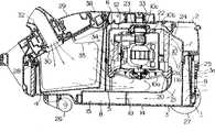
图1表示根据本发明一个实施例的真空吸尘器主要部分的纵向断面图;Figure 1 shows a longitudinal sectional view of a main part of a vacuum cleaner according to an embodiment of the present invention;
图2是整个真空吸尘器的透视图;Figure 2 is a perspective view of the entire vacuum cleaner;
图3是一个下机壳和与其相联的部件的分解透视图;Fig. 3 is an exploded perspective view of a lower casing and components associated therewith;
图4是底朝上颠倒的下机壳的分解透视图;Fig. 4 is an exploded perspective view of the bottom upside-down lower casing;
图5是一个上机壳的透视图;Fig. 5 is a perspective view of an upper casing;
图6是一个隔音箱的水平断面图;Fig. 6 is a horizontal sectional view of a soundproof box;
图7是下机壳的水平断面图,表示出一条消音通路;Figure 7 is a horizontal sectional view of the lower casing, showing a sound-absorbing passage;
图8是标示消音效果的频率特性的示意图。FIG. 8 is a schematic diagram showing the frequency characteristics of the noise canceling effect.
下面参照附图说明发明的实施例。Embodiments of the invention will be described below with reference to the drawings.
参见图1,一台真空吸尘器包括一个被分成上机壳2,下机壳3两部分的机壳1,上、下机壳可互相分离,并且是用合成树脂加工成的,以密封分隔方式限定在机壳1内的有集尘室4,一条与集尘室4连通的联系通道5,一个与联系通道5连通的电动抽风机容室6,一条与电动抽风机容室6连通的排气通道7,一条与排气通道7连通的消音通道8,以及一个与消音通道8连通的排气室9。Referring to Fig. 1, a vacuum cleaner includes a casing 1 divided into two parts, an
限定电动抽风机容室6的分隔壁是由同下机壳3整体加工成并将电动抽风机10的抽风机组件10a罩住的管形凸缘11,以及一个与机壳1分开单独制作并将电动抽风机10的电机组件10b罩住的隔音箱12组成。隔音箱12被可拆卸地安装到管形凸缘11上是以这样的方式进行的,即管形凸缘11的开口端面的整个边缘密封地嵌入沿隔音箱12开口端面的整个边缘制成的槽12a中,而后,如图6所示用螺钉13和13a把隔音箱12连接在管形凸缘11上。The partition wall that limits the
集尘室4相对电动抽风机容室6被并排设置。联系通道5与由电动抽风机容室6限定的分隔壁下部连通,也就是与管形凸缘11侧壁的下部连通。排气通道7与由电动抽风机容室6限定的分隔壁上部连通,即与隔音箱12侧壁的上部连通。The dust collection chamber 4 is arranged side by side with respect to the
排气通道7有一个由一段与隔首箱12为一体的箱壁所限定的流入端部。排气通道7沿隔音箱12侧壁向下延伸。该排气通道7还有一个由一段与管形凸缘11为一体的壁板所限定的流出端部,该管形凸缘11是上下机壳3整体构成的。隔音箱12是用比上、下机壳2和3耐热程度高的材料制成的。The
消音通道8是由下机壳3的底面与密封性地固定在该底面上的机箱盖14所限定。消音通道8大体呈U字形,而且与设置在机壳1后部的排气室9连通。吸音材料15贴缚在机箱盖14的内面上。机箱盖14是用合成树脂制成的。排气通道7与消音通道8通过一个在下机壳3的底面上形成的开口而互相连通。The sound deadening channel 8 is defined by the bottom surface of the
排气通道7具有的通道横截面积小于隔音箱12的横截面积。消音通道8具有的横截面积大于排气通道7的横截面积。排气室9具有的通道横截面积大于消音通道8的该面积。The
如图3中所示,在联系通道5的进口处制成有若干小肋板16,用于防止像纸片或类似的较大尘粒进入电动抽风机容室6。沿着从联系通道5到设置在电动抽风机容室6内的电动抽风机10延伸的流动通路装有一条导向肋板17。该导向肋板17是与下机壳3整体构成的,并且其作用是将空气顺利从集尘室4导向电动抽风机10的抽风机组件10a的进口。As shown in FIG. 3 , several small ribs 16 are formed at the entrance of the communication passage 5 to prevent larger dust particles like paper sheets or similar from entering the
从电动抽风机容室6延伸到排气通道7的流动通道所限定的内壁面具有能使排放气顺利流动的构形。从排气通道7延伸到消音通道8的流动通路所限定的内壁面具有能使排放气顺利流动的构形。The inner wall surface defined by the flow channel extending from the
如图4中清楚表示的,消音通道8里设置着若干个整流叶片18,用来使排放气流方向改变180°以便顺利地将排放气流导向排气室9。整流叶片18是整体地成形于下机壳3的底面。一个整流网19设置在整流叶片18的上游端一侧,即相应于整流叶片18的流入端那一侧。整流网19用具有能防止气流噪音产生的细网眼的合成树脂网或金属网制成。As shown clearly in FIG. 4 , several rectifying vanes 18 are arranged in the muffler channel 8 to change the direction of the exhaust airflow by 180° so that the exhaust airflow is guided to the
排气通道7的流入端部由与隔音箱12为一体的箱壁板限定。排气通道7的流出端部由管形凸缘11限定。将隔音箱12安装到管形凸缘11上,从而最终形成了用来把排放气流从电动抽风机容室6引导到消音室8的排气通道7。The inflow end of the
电动抽风机10以这样的方式被垂直设置在电动抽风机容室6里,即抽风机组件10a位于电机组件10b的下方。在管形凸缘11的内周壁面的下部加工有一装配段21。一个环状第一弹性件20被装在装配段21上,用于密封地隔绝由电动抽风机10的抽风机组件10a所产生的振动。装配段21是由一个与下机壳3整体设置的环状凸肋形成的。The electric blower 10 is vertically arranged in the
隔音箱12在其顶部形成有一装配段23,在此段内装有第二弹性件22,用来以隔振的方式支承电动抽风机10的电机组件10b。装配段23有一凹槽,第二弹性件22可嵌入该凹槽中。各第一、第二弹性件21和22是用橡胶隔振体构成的。围绕电动抽风机10的电机组件10b的外周边没有一吸音盖24。排气通道7的流入端部与电动抽风机10的电机组件10b的外周边相切地延伸。如果需要,可将吸音材料附在隔音箱12的内周面上。第二弹性元件22是以这样方式装到电动抽风机10上的,即在电机组件10b的主轴的轴承突起10c上的外周面安装第二弹性元件22。The
一个排气窗3a成形于下机壳3的后壁板内,并与排气室9连通。在排气窗3a上游端设置有一个细尘过滤器25,该过滤器可从机壳1外侧拆卸。如图4所示,在下机壳3的底面装有一个脚轮26和一对转轮27,27a。An exhaust window 3 a is formed in the rear wall panel of the
上机壳2装到下机壳3上通过螺栓28固定,以最终构成机壳1。在上机壳2上形成有开口,即集尘室4的开口,它由一封闭罩29盖住,该封闭罩被装到上机壳2上,以便可以打开和关闭。封闭罩29在其内形成有一个吸口30。一吸尘软管31的管接头32(见图2)适合可拆卸地装在吸口30处。手抓柄33装在上机壳2的顶面。The
用元纺纤维或类似材料制成的集尘盒34被可拆卸地装在集尘室4里。一种如纸袋之类的可随时处理的过滤纸袋35放在集尘盒34内。过滤纸袋35的进口在封闭罩29关上时便在封闭罩内密封地固定在吸口30处。A
如图2中所示,吸尘软管31通过管接头32安装到封闭罩29上,这样的装配方式使吸尘软管31可以转动360度。加长管36和吸咀37可以连接到吸尘软管31。封闭罩29在其内带有一个可放香料的腔室38。在上、下机壳2和3的前端设置一个提机壳1用的抓手。As shown in FIG. 2 , the dust suction hose 31 is mounted on the
上机壳2中放置着一个集尘计量表。封闭罩29用合成树脂制成并且被设计成当封闭罩29关闭时能在封闭罩29与上机壳2的开口间提供密封。如果需要,可在集尘室4和联系通道5之间设置一个有粗网眼的过滤器。要求用带细网眼的过滤材料制成集尘盒34,以便使集尘盒34本身能在未安装过滤袋35时用来收集灰尘。该集尘盒34被设计成当该盒弄脏污时可用水冲洗。A dust collection meter is placed in the
电动抽风机10是如此安排的,来自抽风机10a的气流先冷却电机10b的内部,而后经设置在外周的窗孔以电机外周边相切的方向流出。该电机组件10b装入一个整流式电机机构。The electric blower 10 is arranged in such a way that the airflow from the
如图3所示,一块电路板39有一个凸片39a,该凸片位于由隔音箱12和管形凸缘11限定的排气通道7中。机壳1内邻近电动抽风机容室6限定着一个电源线卷容室40。隔音箱12的一部分上壁板构成有便于装配电路板39的平面段12b,该段平面位于与隔音箱12的外周边邻近处。平面段12b其内形装有一个狭缝状的通孔12c,电路板的凸片39a可插进该孔中。As shown in FIG. 3, a circuit board 39 has a tab 39a which is located in the
按上述方案,当电动抽风机10转动时,空气经吸口30进入过滤袋35并穿过过滤袋35和集尘盒34。空气又经联系通道5流进电动抽风机容室6,并且由导向肋板17引导顺利流入抽风机组件10a。流出抽风机组件10a的空气冷却电机组件10b的内部,随后,膨胀并流出,成为排放气流流到围绕电机10b外周的空间。由电动抽风机10产生风声噪音和滚珠轴承的旋转噪音均被隔音箱12隔绝掉。从电动抽风机容室6流出的排放气进入排气通道7并且在其内被压缩。该排放气沿排气通道7向下流,随后,流进消音通道8并在其内膨胀。进入消音通道8的排放气流被若干个整流叶片18分成多股气流,这些股气流同时被整流叶片18改变流向180度。排放气流进入排气室9并且经排气窗3a被排放到机壳1的外部。在消音通道8里被分成多股的气流又互相合在一起,而后该气流进入排气室9并在其内膨胀。According to the above scheme, when the electric blower 10 rotates, the air enters the
由于在空气流经排气通道7,消音通道8和排气室9过程中被反复压缩和膨胀,因此降低了由电动抽风机10的转动造成的噪声音量。通过吸音材料15进一步降低噪声音量。Since the air is repeatedly compressed and expanded when it flows through the
穿过集尘盒34的微细灰尘和由电动抽风机10的转动产生的刷损粉末之类的微细灰尘被细尘过滤器25滤掉,不会从电动抽风机容室6,排气通道7,消音通道8和排气室9漏到机壳1的内部和外部。因此,机壳1内部避免被弄脏,而且经排气窗3a流出的只是清洁空气。The fine dust passing through the
电动抽风机10转动所产生的噪声通过包括隔音箱12和上机壳2在内的双层壁板被隔绝。于是,在机壳1上方位置上所能听到的噪声相当低。由于利用下机壳3的底面使消音通道8构成U形,因此容易把消音通道8做得长些,而且不必增加机壳1的尺寸。The noise generated by the rotation of the electric exhaust fan 10 is insulated by the double wall panels including the
当采用大功率电动抽风机10而且电机10b内的冷却气流量因集尘盒34或过滤袋35堵塞面减少时,流出电机10b的排放气便会导致高温。所以,隔音箱12被加热量很高温度。然而,由于隔音籍12是用耐高温材料制成的,因此可以防止隔音箱12的受热变形。由于隔音箱12是分离机壳1单独构成的而且按此安排单独安装到管形凸缘11上,因此按此连接,只有隔音箱12用面高热材料制作,而机壳1可用一般的廉价合成树脂制成。When adopting high-power electric blower 10 and the cooling air flow rate in the
由于放入电动抽风机容室6的电动抽风机10是抽风机10a位于电机组件10b的下方,因此电动抽风机10的重量和由电动抽风机10的转动导致负压所产生的推力都作用在同一方向并施加于第一弹性件20的整个区域。因此,第一弹性件20随着强而均匀的推力紧靠在装配段21上。这样就提供了稳定可靠的密封和产生隔振效果。Because the electric blower 10 that puts into the
电动抽风机10装入下机壳3是按下面的方式进行的。即,首先预先将第一弹性件20,第二弹性件22和吸音盖24装到电动抽风机10上。而后,将电动抽风机10插入管形凸缘11,则第一弹性件20便被装到装配段21上了。然后,把隔音箱12盖到电动抽风机10上,并用螺钉13和13a固定到管形凸缘11上。这样,就完成了电动抽风机10的装入。不一定非要预先把第一和第二弹性件20和22及吸音盖24装到电动抽风机10上。也就是说,可以这样把电动抽风机10装入下机壳3;先将第一弹性件20装到管形凸缘11里的装配段21上,然后把电动抽风机10装进第一弹性件20;随后再把吸音盖24和第二弹性件22装到电动抽风机10上,最后将隔音箱12盖在电动抽风机10上。Electric exhaust fan 10 is packed into
图8是频率特性的示意图,标示出根据所述实施例的真空吸尘器中由于装入隔音箱12而实现的消音效果。噪声是在上机壳2上方一米的位置测量的。a线代表先有技术,而b线表示上述实施例。从频率特性可以理解上述实施例的消音效果与先有技术相比得到了相当可观的改善。FIG. 8 is a graph of frequency characteristics, indicating the sound attenuation effect achieved by incorporating the
虽然上述实施例中联系通道5相对短些,但其长度可以增加。相反,联系通道5可以仅用一个通孔来加工成,通过该孔集尘室4和电动抽风机容室6相互连通。另外,如果采用小功率电动抽风机则电动抽风机的转动噪音很低,那末可以不用设消音通道8。在这种情况下,排气通道7直接与排气室9连通。Although the communication channel 5 is relatively short in the above embodiments, its length can be increased. On the contrary, the communication channel 5 can be processed with only one through hole, through which the dust collection chamber 4 and the
在上述实施例中,空气可以经联系通道5电动抽风机容室6,排气通道7和消音通道8能使空气从集尘室4流到排气室,还能经排气窗3a排放到机壳1的外部且不会漏入机身壳体1内的空间。相应地除了排气窗3a外,还设置细尘过滤器25,这一措施既能保证除掉从集尘室4流进排气室9的微细灰尘,还能除掉像由电动抽风机10产生的刷损粉末那样的微细灰尘。从而可以进行更清洁的吸尘操作。In the above-mentioned embodiment, the air can pass through the connecting channel 5
Claims (24)
Translated fromChineseApplications Claiming Priority (2)
| Application Number | Priority Date | Filing Date | Title |
|---|---|---|---|
| JP109039/87 | 1987-05-06 | ||
| JP62109039AJPH0665332B2 (en) | 1987-05-06 | 1987-05-06 | Vacuum cleaner |
Publications (2)
| Publication Number | Publication Date |
|---|---|
| CN88102583A CN88102583A (en) | 1988-11-23 |
| CN1040720Ctrue CN1040720C (en) | 1998-11-18 |
Family
ID=14500055
Family Applications (1)
| Application Number | Title | Priority Date | Filing Date |
|---|---|---|---|
| CN88102583AExpired - Fee RelatedCN1040720C (en) | 1987-05-06 | 1988-05-05 | vacuum cleaner |
Country Status (5)
| Country | Link |
|---|---|
| EP (1) | EP0289987B1 (en) |
| JP (1) | JPH0665332B2 (en) |
| KR (1) | KR960014807B1 (en) |
| CN (1) | CN1040720C (en) |
| DE (1) | DE3886809T2 (en) |
Families Citing this family (33)
| Publication number | Priority date | Publication date | Assignee | Title |
|---|---|---|---|---|
| JP2907894B2 (en)* | 1989-09-29 | 1999-06-21 | 株式会社日立製作所 | Electric vacuum cleaner |
| JPH03182223A (en)* | 1989-12-08 | 1991-08-08 | Matsushita Electric Ind Co Ltd | vacuum cleaner |
| DE69104891T2 (en)* | 1990-04-18 | 1995-03-16 | Hitachi Ltd | Vacuum cleaner. |
| JP3047984B2 (en)* | 1990-04-18 | 2000-06-05 | 株式会社日立製作所 | Electric vacuum cleaner |
| USD357560S (en) | 1993-12-27 | 1995-04-18 | Hohulin Samuel E | Vacuum cleaner |
| CA2136505C (en)* | 1994-04-21 | 2004-08-17 | Robert C. Berfield | Motor mounting apparatus |
| DE19733687B4 (en)* | 1996-08-12 | 2005-04-21 | Samsung Kwangju Electronics Co., Ltd. | Motor fan for a cleaning device |
| KR0136300Y1 (en)* | 1996-09-10 | 1999-02-01 | 최진호 | Motor of a vacuum cleaner |
| FR2756720A1 (en)* | 1996-12-05 | 1998-06-12 | Lg Electronics Inc | VACUUM |
| GB2321393B (en)* | 1997-01-10 | 2001-07-25 | White Consolidated Ind Inc | Air filtrating self-propelled upright vacuum cleaner |
| EP1172059A1 (en) | 2000-07-14 | 2002-01-16 | Nilfisk Advance A/S | A suction apparatus with noise reduction means |
| FR2826851B1 (en) | 2001-07-03 | 2004-08-06 | Nielsen Innovation | HIGH EFFICIENCY SELF-CONTAINED VACUUM |
| KR100445479B1 (en)* | 2001-12-20 | 2004-08-21 | 엘지전자 주식회사 | Motor housing for vacuum cleaner |
| GB0203147D0 (en)* | 2002-02-11 | 2002-03-27 | Dyson Ltd | An exhaust assembly |
| KR100555205B1 (en)* | 2003-12-31 | 2006-03-03 | 삼성광주전자 주식회사 | Vacuum cleaner |
| DE102005017568B4 (en) | 2005-04-11 | 2024-04-25 | Alfred Kärcher SE & Co. KG | Vacuum cleaner |
| DE102005017702A1 (en) | 2005-04-11 | 2006-10-12 | Alfred Kärcher Gmbh & Co. Kg | Method for cleaning the filter of a vacuum cleaner and vacuum cleaner for carrying out the method |
| CN101489462B (en) | 2006-07-29 | 2011-07-06 | 阿尔弗雷德·凯驰两合公司 | Method for cleaning the filters of a vacuum cleaner and vacuum cleaner for carrying out the method |
| DE502006006920D1 (en)* | 2006-07-29 | 2010-06-17 | Kaercher Gmbh & Co Kg Alfred | VACUUM CLEANER |
| WO2008014797A1 (en) | 2006-07-29 | 2008-02-07 | Alfred Kärcher Gmbh & Co. Kg | Method for cleaning the filters of a vacuum cleaner and vacuum cleaner for carrying out the method |
| CN101484060B (en) | 2006-07-29 | 2012-05-30 | 阿尔弗雷德·凯驰两合公司 | Vacuum cleaner with self-cleaning filter |
| KR100767118B1 (en)* | 2006-10-31 | 2007-10-17 | 삼성광주전자 주식회사 | Vacuum cleaner |
| EP2227998A4 (en)* | 2007-11-22 | 2012-08-08 | Toshiba Kk | Electric cleaner |
| WO2010121656A1 (en) | 2009-04-22 | 2010-10-28 | Alfred Kärcher Gmbh & Co. Kg | Method for cleaning two filters of a suction device for cleaning purposes, and suction device for performing the method |
| DE102009020769A1 (en) | 2009-04-30 | 2010-11-04 | Alfred Kärcher Gmbh & Co. Kg | vacuum cleaning |
| EP2451332B1 (en) | 2009-07-07 | 2018-11-14 | Alfred Kärcher SE & Co. KG | Suction apparatus for cleaning purposes |
| JP5409182B2 (en)* | 2009-08-12 | 2014-02-05 | 日立アプライアンス株式会社 | Electric vacuum cleaner |
| DE102011007206A1 (en)* | 2011-04-12 | 2012-10-18 | BSH Bosch und Siemens Hausgeräte GmbH | Motor arrangement for an electric motor driven household appliance |
| CN102319044B (en)* | 2011-09-14 | 2013-08-21 | 江苏美的春花电器股份有限公司 | Dust collector |
| JP6051174B2 (en)* | 2014-01-31 | 2016-12-27 | 日立アプライアンス株式会社 | Vacuum cleaner mouthpiece and electric vacuum cleaner using the mouthpiece |
| DE102015118650A1 (en)* | 2015-10-30 | 2017-05-04 | Vorwerk & Co. Interholding Gmbh | Cleaning device with soundproofing element |
| EP3866658A1 (en) | 2018-10-19 | 2021-08-25 | Alfred Kärcher SE & Co. KG | Suction machine with sound-angle element |
| CN114747974A (en)* | 2022-04-13 | 2022-07-15 | 添可智能科技有限公司 | Handheld vacuum cleaners and cleaning equipment |
Family Cites Families (8)
| Publication number | Priority date | Publication date | Assignee | Title |
|---|---|---|---|---|
| US2424253A (en)* | 1944-08-05 | 1947-07-22 | Eureka Williams Corp | Suction cleaner |
| US2889006A (en)* | 1955-06-07 | 1959-06-02 | Pauline A Ortega | Pneumatic cleaning device |
| US2930446A (en)* | 1957-03-18 | 1960-03-29 | Singer Mfg Co | Canister type vacuum cleaners |
| JPS5842793Y2 (en)* | 1978-09-27 | 1983-09-28 | カルソニックカンセイ株式会社 | Heat exchanger |
| DE2944749A1 (en)* | 1979-11-06 | 1981-05-14 | Rommag P. Wörwag & Co., Romanshorn | VACUUM CLEANER |
| DE3225258C2 (en)* | 1982-07-06 | 1985-11-28 | Guido Oberdorfer Wap-Maschinen, 7919 Bellenberg | Vacuum cleaner |
| JPS61115529A (en)* | 1984-11-09 | 1986-06-03 | 株式会社日立製作所 | vacuum cleaner |
| JPS6216730A (en)* | 1985-07-15 | 1987-01-24 | 松下電器産業株式会社 | vacuum cleaner |
- 1987
- 1987-05-06JPJP62109039Apatent/JPH0665332B2/ennot_activeExpired - Fee Related
- 1988
- 1988-05-02KRKR1019880005069Apatent/KR960014807B1/ennot_activeExpired - Fee Related
- 1988-05-03DEDE88107080Tpatent/DE3886809T2/ennot_activeExpired - Fee Related
- 1988-05-03EPEP88107080Apatent/EP0289987B1/ennot_activeExpired - Lifetime
- 1988-05-05CNCN88102583Apatent/CN1040720C/ennot_activeExpired - Fee Related
Also Published As
| Publication number | Publication date |
|---|---|
| EP0289987A3 (en) | 1990-02-07 |
| JPH0665332B2 (en) | 1994-08-24 |
| CN88102583A (en) | 1988-11-23 |
| JPS63275313A (en) | 1988-11-14 |
| KR880013524A (en) | 1988-12-21 |
| DE3886809D1 (en) | 1994-02-17 |
| EP0289987A2 (en) | 1988-11-09 |
| DE3886809T2 (en) | 1994-05-05 |
| KR960014807B1 (en) | 1996-10-21 |
| EP0289987B1 (en) | 1994-01-05 |
Similar Documents
| Publication | Publication Date | Title |
|---|---|---|
| CN1040720C (en) | vacuum cleaner | |
| KR960010998B1 (en) | Vacuum cleaner having silencer mechanism | |
| RU2323674C1 (en) | Vacuum cleaner and method of reduction of noise, prodused by vacuum cleaner | |
| CN1305426C (en) | Vacuum cleaner | |
| US5737797A (en) | Central vacuum with acoustical damping | |
| GB2117229A (en) | Vacuum cleaner with noise suppressor | |
| KR100349292B1 (en) | Electric cleaner | |
| JP2844987B2 (en) | Electric vacuum cleaner | |
| JP2000354562A (en) | Electric vacuum cleaner | |
| JP4419586B2 (en) | Electric blower unit and vacuum cleaner incorporating the same | |
| JP2000120599A (en) | Electric blower and vacuum cleaner equipped with the same | |
| JP3528769B2 (en) | Electric vacuum cleaner | |
| KR960014580B1 (en) | Power cord cooling structure of vacuum cleaner winding device | |
| CN111852907A (en) | Blower and blower case | |
| KR100270800B1 (en) | A noise decreasing device of a vacuum cleaner | |
| CN220735305U (en) | Air duct assembly and cleaning robot | |
| JP2001061728A (en) | Electric vacuum cleaner | |
| KR0163288B1 (en) | Dry type vacuum cleaner | |
| JPS6135168Y2 (en) | ||
| JPH0547204B2 (en) | ||
| KR19990033890A (en) | Sound absorption room of vacuum cleaner | |
| JPS6340209Y2 (en) | ||
| JPH0583400U (en) | Dust collector for woodwork with silencer | |
| JPS6325772B2 (en) | ||
| JPH10117970A (en) | Stationary vacuum cleaner |
Legal Events
| Date | Code | Title | Description |
|---|---|---|---|
| C10 | Entry into substantive examination | ||
| SE01 | Entry into force of request for substantive examination | ||
| C06 | Publication | ||
| PB01 | Publication | ||
| C14 | Grant of patent or utility model | ||
| GR01 | Patent grant | ||
| C15 | Extension of patent right duration from 15 to 20 years for appl. with date before 31.12.1992 and still valid on 11.12.2001 (patent law change 1993) | ||
| OR01 | Other related matters | ||
| C19 | Lapse of patent right due to non-payment of the annual fee | ||
| CF01 | Termination of patent right due to non-payment of annual fee |