CN103890958A - System and method for increasing voltage in a photovoltaic inverter - Google Patents
System and method for increasing voltage in a photovoltaic inverterDownload PDFInfo
- Publication number
- CN103890958A CN103890958ACN201280048660.6ACN201280048660ACN103890958ACN 103890958 ACN103890958 ACN 103890958ACN 201280048660 ACN201280048660 ACN 201280048660ACN 103890958 ACN103890958 ACN 103890958A
- Authority
- CN
- China
- Prior art keywords
- voltage
- inverter
- array group
- pair
- array
- Prior art date
- Legal status (The legal status is an assumption and is not a legal conclusion. Google has not performed a legal analysis and makes no representation as to the accuracy of the status listed.)
- Pending
Links
- 238000000034methodMethods0.000titleclaimsabstractdescription32
- 238000003491arrayMethods0.000claimsabstractdescription26
- 230000005855radiationEffects0.000claimsabstractdescription13
- 230000001276controlling effectEffects0.000description15
- 238000006243chemical reactionMethods0.000description5
- 238000010586diagramMethods0.000description4
- 238000004146energy storageMethods0.000description3
- 230000004044responseEffects0.000description3
- 230000009286beneficial effectEffects0.000description2
- 239000003990capacitorSubstances0.000description2
- 230000007246mechanismEffects0.000description2
- 230000008707rearrangementEffects0.000description2
- 230000001105regulatory effectEffects0.000description2
- 206010027336Menstruation delayedDiseases0.000description1
- 230000004913activationEffects0.000description1
- 238000003306harvestingMethods0.000description1
- 230000004048modificationEffects0.000description1
- 238000012986modificationMethods0.000description1
- 238000006467substitution reactionMethods0.000description1
Images


Classifications
- H—ELECTRICITY
- H02—GENERATION; CONVERSION OR DISTRIBUTION OF ELECTRIC POWER
- H02J—CIRCUIT ARRANGEMENTS OR SYSTEMS FOR SUPPLYING OR DISTRIBUTING ELECTRIC POWER; SYSTEMS FOR STORING ELECTRIC ENERGY
- H02J1/00—Circuit arrangements for DC mains or DC distribution networks
- H02J1/08—Three-wire systems; Systems having more than three wires
- H02J1/082—Plural DC voltage, e.g. DC supply voltage with at least two different DC voltage levels
- H—ELECTRICITY
- H02—GENERATION; CONVERSION OR DISTRIBUTION OF ELECTRIC POWER
- H02J—CIRCUIT ARRANGEMENTS OR SYSTEMS FOR SUPPLYING OR DISTRIBUTING ELECTRIC POWER; SYSTEMS FOR STORING ELECTRIC ENERGY
- H02J1/00—Circuit arrangements for DC mains or DC distribution networks
- H02J1/10—Parallel operation of DC sources
- H—ELECTRICITY
- H10—SEMICONDUCTOR DEVICES; ELECTRIC SOLID-STATE DEVICES NOT OTHERWISE PROVIDED FOR
- H10F—INORGANIC SEMICONDUCTOR DEVICES SENSITIVE TO INFRARED RADIATION, LIGHT, ELECTROMAGNETIC RADIATION OF SHORTER WAVELENGTH OR CORPUSCULAR RADIATION
- H10F77/00—Constructional details of devices covered by this subclass
- H10F77/95—Circuit arrangements
- H10F77/953—Circuit arrangements for devices having potential barriers
- H10F77/955—Circuit arrangements for devices having potential barriers for photovoltaic devices
- Y—GENERAL TAGGING OF NEW TECHNOLOGICAL DEVELOPMENTS; GENERAL TAGGING OF CROSS-SECTIONAL TECHNOLOGIES SPANNING OVER SEVERAL SECTIONS OF THE IPC; TECHNICAL SUBJECTS COVERED BY FORMER USPC CROSS-REFERENCE ART COLLECTIONS [XRACs] AND DIGESTS
- Y02—TECHNOLOGIES OR APPLICATIONS FOR MITIGATION OR ADAPTATION AGAINST CLIMATE CHANGE
- Y02E—REDUCTION OF GREENHOUSE GAS [GHG] EMISSIONS, RELATED TO ENERGY GENERATION, TRANSMISSION OR DISTRIBUTION
- Y02E10/00—Energy generation through renewable energy sources
- Y02E10/50—Photovoltaic [PV] energy
Landscapes
- Engineering & Computer Science (AREA)
- Power Engineering (AREA)
- Inverter Devices (AREA)
- Control Of Electrical Variables (AREA)
- Life Sciences & Earth Sciences (AREA)
- Sustainable Development (AREA)
- Sustainable Energy (AREA)
Abstract
Translated fromChineseDescription
Translated fromChinese技术领域technical field
本发明总地涉及电力转换,并且尤其涉及光伏(PV)逆变器拓扑及其控制方法,其为PV逆变器提供增大的工作电压。The present invention relates generally to power conversion, and more particularly to photovoltaic (PV) inverter topologies and control methods thereof, which provide increased operating voltages for PV inverters.
背景技术Background technique
光伏(PV)电池产生直流(DC)功率,其中DC电流的水平取决于太阳辐射,以及DC电压的水平取决于温度。当需要交流(AC)功率时,使用逆变器将DC能量转换成AC能量,诸如适于传送至电网的AC能量。典型的PV逆变器使用两级来用于功率处理。PV逆变器的第一级被配置为调整来自PV电池阵列的宽范围变化的DC电压,以提供恒定的DC电压输出。PV逆变器的第二级被配置为将恒定的DC电压转换成AC电流。通常,第一级包括升压转换器,以及第二级包括单相或三相逆变器系统。Photovoltaic (PV) cells generate direct current (DC) power, where the level of DC current depends on solar radiation, and the level of DC voltage depends on temperature. When alternating current (AC) power is required, an inverter is used to convert the DC energy to AC energy, such as AC energy suitable for delivery to the grid. A typical PV inverter uses two stages for power handling. The first stage of the PV inverter is configured to regulate the widely varying DC voltage from the PV cell array to provide a constant DC voltage output. The second stage of the PV inverter is configured to convert a constant DC voltage into AC current. Typically, the first stage includes a boost converter, and the second stage includes a single-phase or three-phase inverter system.
为了将PV阵列的变化的DC电压转换成电网的固定频率的AC电压,许多PV逆变器利用两级转换电力线路,其使用DC链路作为中间能量存储步骤,这意味着转换器首先将不稳定的PV阵列电压转换成稳定的DC电压。PV逆变器随后将稳定的电压转换成可以注入电网的AC电流。可替换地,PV逆变器可以代替地利用单级转换电力线路,其中使用变压器来提高AC电压。To convert the varying DC voltage of the PV array into the fixed frequency AC voltage of the grid, many PV inverters utilize a two-stage conversion of the power line, which uses the DC link as an intermediate energy storage step, which means that the converter will first not The stable PV array voltage is converted into a stable DC voltage. A PV inverter then converts the regulated voltage into AC current that can be injected into the grid. Alternatively, a PV inverter may instead utilize a single stage to convert the power line, where a transformer is used to step up the AC voltage.
关于典型的两级PV逆变器,一个缺点是这种逆变器由于第二级而固有地低效并且更耗费。即,两级逆变器的效率是单级效率的倍数,每一级典型地引起系统损耗的一半。由此,去除PV逆变器的一级是有利的,即去除DC-DC转换器,以增加逆变器的效率。然而,可以认识到,去除DC-DC转换器将导致逆变器具有较小的DC工作窗口,因为单级PV逆变器被认为具有较小的DC电压工作窗口。由此,在去除DC-DC转换器时,需要一种机构来最小化PV阵列至PV逆变器的输出的变化。One disadvantage with typical two-stage PV inverters is that such inverters are inherently less efficient and more expensive due to the second stage. That is, the efficiency of a two-stage inverter is a multiple of the efficiency of a single stage, with each stage typically causing half the system losses. Thus, it is advantageous to remove one stage of the PV inverter, ie to remove the DC-DC converter, in order to increase the efficiency of the inverter. However, it can be appreciated that removing the DC-DC converter will result in an inverter with a smaller DC operating window, since single stage PV inverters are considered to have a smaller DC voltage operating window. Thus, a mechanism is needed to minimize variations in the output of the PV array to the PV inverter when the DC-DC converter is removed.
现有的PV阵列和PV逆变器配置的另一公认的缺点是由PV阵列组产生的DC功率和电压会宽范围地变化,因为由此产生的DC功率/电压的量取决于PV阵列所接收到的太阳辐射的量。因此,如果从PV阵列接收到的DC电压的量小于最佳工作电压水平,则PV逆变器可能不总是在最佳工作电压下工作。这可能在多云天气或一天中的早/晚的期间发生,因为由PV阵列接收到的太阳辐射的水平在这些时间可能不足。有益的是,如果由PV逆变器从PV阵列接收到的DC电压的变化可以被最小化并且可以从PV阵列提供足够的DC电压以允许PV逆变器在最佳工作电压或者接近最佳工作电压工作,以使得PV逆变器以较高的或峰值效率工作。Another well-recognized shortcoming of existing PV array and PV inverter configurations is that the DC power and voltage generated by a PV array group can vary widely, since the amount of DC power/voltage generated thereby depends on the PV array The amount of solar radiation received. Therefore, if the amount of DC voltage received from the PV array is less than the optimum operating voltage level, the PV inverter may not always operate at the optimum operating voltage. This may occur during cloudy weather or early/late periods of the day, as the level of solar radiation received by the PV array may be insufficient at these times. It would be beneficial if the variation in the DC voltage received by the PV inverter from the PV array could be minimized and enough DC voltage could be supplied from the PV array to allow the PV inverter to operate at or near optimal operating voltage voltage so that the PV inverter operates at higher or peak efficiency.
因此,期望提供一种PV逆变器,其与传统的两级PV逆变器相比,使用单级拓扑以最小化系统损耗,同时仍然提供两级设计的较大的DC工作窗口。还期望提供一种PV逆变器及其控制技术,其最小化PV阵列至PV逆变器的输出的变化并且确保PV逆变器一直以峰值效率工作。Therefore, it is desirable to provide a PV inverter that uses a single-stage topology to minimize system losses, while still providing the larger DC operating window of the two-stage design, compared to conventional two-stage PV inverters. It is also desirable to provide a PV inverter and control technique thereof that minimizes variations in the output of the PV array to the PV inverter and ensures that the PV inverter operates at peak efficiency at all times.
发明内容Contents of the invention
本发明提供一种用于控制提供至PV逆变器的DC电压的系统和方法。提供一种开关元件,其位于一对PV阵列组和PV逆变器之间,并且以串联配置和并联配置中之一提供PV阵列组的动态重新配置,从而控制DC-AC功率逆变器从所述一对PV阵列组接收到的DC电压的水平。The present invention provides a system and method for controlling DC voltage provided to a PV inverter. A switching element is provided that is positioned between a pair of PV array groups and a PV inverter and that provides dynamic reconfiguration of the PV array groups in one of a series configuration and a parallel configuration, thereby controlling a DC-AC power inverter from The level of DC voltage received by the pair of PV array groups.
根据本发明的一个方面,PV系统包括一对PV阵列组,其被配置为从所接收到的太阳辐射产生直流(DC)输出,该对PV阵列组包括第一PV阵列组和第二PV阵列组。PV系统还包括DC-AC功率逆变器,其电耦合至所述一对PV阵列组以从其接收DC输出并将DC输出转换成AC输出。PV系统还包括开关元件,其位于所述一对PV阵列组和DC-AC功率逆变器之间,开关元件被配置为选择性地以串联配置和并联配置中之一将所述一对PV阵列组连接至DC-AC功率逆变器,从而控制由DC-AC功率逆变器从所述一对PV阵列组接收到的DC电压的水平。According to one aspect of the invention, a PV system includes a pair of PV array groups configured to generate a direct current (DC) output from received solar radiation, the pair of PV array groups comprising a first PV array group and a second PV array Group. The PV system also includes a DC-AC power inverter electrically coupled to the pair of PV array groups to receive a DC output therefrom and convert the DC output to an AC output. The PV system also includes a switching element positioned between the pair of PV array groups and the DC-AC power inverter, the switching element being configured to selectively connect the pair of PV arrays in one of a series configuration and a parallel configuration. The array sets are connected to a DC-AC power inverter to control the level of DC voltage received by the DC-AC power inverter from the pair of PV array sets.
根据本发明的另一个方面,提供一种用于控制从多个PV阵列提供至PV逆变器的DC电压的方法。该方法包括:测量来自一对PV阵列组的DC电压输出,该对PV阵列组包括第一PV阵列组和第二PV阵列组;并将来自第一和第二PV阵列组的DC电压输出与PV逆变器的预定电压工作窗口进行比较,其中所述预定电压工作窗口具有与其相关联的电压上限和下限。该方法还包括基于来自第一和第二PV阵列组的DC电压输出与PV逆变器的预定电压工作窗口的比较来控制连接在PV逆变器和所述一对PV阵列组之间的开关装置的切换,从而使所述一对PV阵列组通过开关装置选择性地以串联配置和并联配置中之一连接至PV逆变器。According to another aspect of the present invention, there is provided a method for controlling DC voltage provided from a plurality of PV arrays to a PV inverter. The method includes: measuring a DC voltage output from a pair of PV array groups, the pair of PV array groups comprising a first PV array group and a second PV array group; and comparing the DC voltage output from the first and second PV array groups with The predetermined voltage operating window of the PV inverter is compared, wherein the predetermined voltage operating window has an upper voltage limit and a lower voltage limit associated therewith. The method also includes controlling a switch connected between the PV inverter and the pair of PV array groups based on a comparison of the DC voltage output from the first and second PV array groups to a predetermined voltage operating window of the PV inverter switching of the device so that the pair of PV array groups are selectively connected to the PV inverter in one of a series configuration and a parallel configuration through the switching device.
根据本发明的又一方面,一种PV系统包括:PV逆变器,其被配置为将DC功率转换成AC功率,PV逆变器进一步包括:输入端,其电耦合至一对PV阵列组,该输入端被配置为接收由所述一对PV阵列组响应所接收到的太阳辐射而产生的DC功率;多个开关,其被配置为将DC功率转换成AC功率;以及输出端,其被配置为将AC功率传送至负载。PV系统还包括开关元件,其位于所述一对PV阵列组和PV逆变器之间。开关元件被配置为选择性地以串联配置和并联配置中之一将所述一对PV阵列组连接至PV逆变器,从而控制由PV逆变器从所述一对PV阵列组接收到的DC电压的水平。According to yet another aspect of the present invention, a PV system includes a PV inverter configured to convert DC power to AC power, the PV inverter further including an input terminal electrically coupled to a pair of PV array groups an input configured to receive DC power generated by the pair of PV arrays in response to received solar radiation; a plurality of switches configured to convert the DC power to AC power; and an output configured to configured to deliver AC power to the load. The PV system also includes a switching element located between the pair of PV array groups and the PV inverter. The switch element is configured to selectively connect the pair of PV array groups to the PV inverter in one of a series configuration and a parallel configuration, thereby controlling the power received by the PV inverter from the pair of PV array groups. The level of the DC voltage.
通过以下详细描述和附图,本发明的各种其它特征和优点将变得明显。Various other features and advantages of the present invention will become apparent from the following detailed description and accompanying drawings.
附图说明Description of drawings
附图示出目前考虑用于执行本发明的优选实施例。The drawings show the preferred embodiments presently considered for carrying out the invention.
在附图中:In the attached picture:
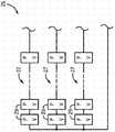
图1是现有技术中已知的光伏逆变器系统的示意图。Fig. 1 is a schematic diagram of a photovoltaic inverter system known in the prior art.
图2是根据本发明实施例的光伏逆变器系统的示意图。Fig. 2 is a schematic diagram of a photovoltaic inverter system according to an embodiment of the present invention.
图3是与图2的光伏逆变器系统一起使用的包括多个并联的光伏串的光伏阵列的示意图。3 is a schematic diagram of a photovoltaic array including multiple parallel photovoltaic strings for use with the photovoltaic inverter system of FIG. 2 .
图4是示出根据本发明实施例的用于控制到达图2的光伏逆变器的DC电压的技术的流程图。4 is a flow diagram illustrating a technique for controlling DC voltage to the photovoltaic inverter of FIG. 2 in accordance with an embodiment of the invention.
具体实施方式Detailed ways
此处阐述的本发明的实施例涉及用于控制由PV逆变器从PV阵列接收到的电压的系统和方法,其提供PV逆变器的增大的工作电压。提供一种PV系统,其包括一对PV阵列组,被配置为产生直流(DC)输出,一DC-AC功率逆变器电耦合至所述一对PV阵列组以从其接收DC输出并将DC输出转换成AC输出。开关元件位于所述一对PV阵列组和DC-AC功率逆变器之间,其被配置为选择性地以串联配置和并联配置中之一连接所述一对PV阵列组和DC-AC功率逆变器,从而控制由DC-AC功率逆变器从所述一对PV阵列组接收到的DC电压的水平。Embodiments of the invention set forth herein relate to systems and methods for controlling the voltage received by a PV inverter from a PV array, which provides an increased operating voltage for the PV inverter. A PV system is provided that includes a pair of PV arrays configured to generate a direct current (DC) output, a DC-AC power inverter electrically coupled to the pair of PV arrays to receive the DC output therefrom and to DC output is converted to AC output. A switching element located between the pair of PV array groups and the DC-AC power inverter is configured to selectively connect the pair of PV array groups and the DC-AC power inverter in one of a series configuration and a parallel configuration. inverter, thereby controlling the level of DC voltage received by the DC-AC power inverter from the pair of PV array groups.
图1示出了现有技术中已知的包括PV逆变器102的光伏(PV)系统100的一般结构。光伏逆变器102利用两级电力线路将来自一个或多个PV阵列104的变化的DC电压转换成用于电网106的固定频率的AC电流。在第一级,如108所示,例如,诸如通过使用DC链路电容器(未示出)来实施中间能量存储步骤。这意味着在第一级108,PV逆变器102首先通过升压转换器将不稳定的PV DC电压110转换成大于电网电压的稳定的DC电压112。PV逆变器102随后通过第二级116将稳定的DC电压112转换成电流114(即,DC-AC转换),电流114之后被注入电网106。PV逆变器102的第二级116使用多个开关装置(未示出),开关装置都以高频开关并且不期望地贡献于两级转换器的总开关损耗。FIG. 1 shows the general structure of a photovoltaic (PV) system 100 including a PV inverter 102 known in the art. Photovoltaic inverter 102 converts the varying DC voltage from one or more PV arrays 104 to a fixed frequency AC current for grid 106 using a two-level power line. At a first stage, as indicated at 108, an intermediate energy storage step is implemented, such as by using DC link capacitors (not shown), for example. This means that in the first stage 108, the PV inverter 102 first converts the unstable PV DC voltage 110 to a stable DC voltage 112 greater than the grid voltage via a boost converter. PV inverter 102 then converts regulated DC voltage 112 to current 114 (ie, DC-AC conversion) via second stage 116 , which is then injected into grid 106 . The second stage 116 of the PV inverter 102 uses multiple switching devices (not shown), all switching at high frequency and undesirably contributing to the overall switching losses of the two-stage converter.
现在参考图2,其示出了根据本发明实施例的光伏(PV)系统10。PV系统10利用PV逆变器12(即,DC-AC功率逆变器)将从多个PV阵列组14、16接收到的变化的DC电压转换成用于电网18的固定频率的AC电流(即,DC-AC转换)。PV逆变器12包括电耦合至PV阵列组14、16以从其接收DC电压的输入端20、将DC功率转换成AC功率的多个开关(未示出)、以及将AC功率传送至诸如电网18的负载的输出端24。Referring now to FIG. 2 , there is shown a photovoltaic (PV)
如图2所示,在PV系统10中提供一对PV阵列组(即,第一PV阵列组14和第二PV阵列组16),第一PV阵列组14和第二PV阵列组16中的每一个被配置为响应所接收到的太阳辐射以产生DC功率。第一PV阵列组14和第二PV阵列组16中的每一个由一个或多个PV阵列26组成,其中,PV阵列26中的每一个包括多个模块/电池。根据一个实施例,并如图3所示,每个PV阵列26包括多个PV串27,每个PV串由串联连接的多个PV模块29组成。再回去参考图2,如图2所示,PV阵列组14、16中每一个的PV阵列26的数量可以变化,例如一个、两个、三个或四个或更多个PV阵列26包括在每个PV阵列组14、16中。然而,根据本发明的实施例,包括在第一PV阵列组14中的PV阵列26的数量应当等于包括在第二PV阵列组16中的PV阵列26的数量,以使包括在第一和第二PV阵列组14、16中的PV阵列26的总数量是偶数。As shown in FIG. 2 , a pair of PV array groups (i.e., a first
如图2所示,PV阵列组14、16通过开关元件或装置28电耦合至PV逆变器12,开关元件或装置28位于PV阵列组14、16和PV逆变器12之间。根据一个实施例,开关元件28是连接接触器(tie contactor)30的阵列的形式,但可以认识到,开关元件28还可以是任意数量的其他开关元件或装置的形式,包括继电器、IGBT、SCR、断路器、小接触器的子阵列或其它合适的开关装置。开关元件28可以集成到PV逆变器12或者被配备为与转换器分离的机构。在操作中,开关元件28用于选择性地以串联配置和并联配置中之一将一对PV阵列组14、16连接至PV逆变器12,从而控制由PV逆变器12从所述一对PV阵列组14、16接收到的DC电压的水平。As shown in FIG. 2 ,
通过选择性地以串联配置或并联配置将第一和第二PV阵列组14、16连接至PV逆变器12,可以控制从所述PV阵列组14、16提供至PV逆变器12的电压的量/水平。即,与以并联配置连接第一和第二PV阵列组14、16时由PV逆变器12接收到的DC电压的水平相比,以串联配置将第一和第二PV阵列组14、16连接至PV逆变器12用于“加倍”由PV逆变器12接收到的DC电压的水平。如此处所使用的,术语“加倍”是指包括与在并联配置中获得的DC电压相比由串联配置提供的DC电压的实际加倍以及DC电压的近似加倍,因为认识到第一PV阵列组14和第二PV阵列组16的电压输出可能不同并且以串联配置的其配置可能由此不精确地加倍于并联配置的其配置。By selectively connecting the first and second
PV逆变器12的工作电压的这种控制对于PV系统10的工作是特别有益的,因为认识到由PV阵列组14、16产生的DC功率和电压取决于由PV阵列26所接收到的太阳辐射的量并且由此是高度可变的。因此,选择性地以由开关元件20提供的串联配置或并联配置将第一和第二PV阵列组14、16连接至PV逆变器12允许控制PV逆变器12工作所处的工作电压。由PV逆变器12从所述一对PV阵列组14、16接收到的DC电压的变化可以由此被最小化,并且PV逆变器12可以在DC电压工作窗口内的最佳工作电压下工作,从而使PV逆变器12以较高的或峰值效率工作。This control of the operating voltage of the
为了控制开关元件28的启动/切换、以及从PV阵列组14、16提供给PV逆变器12的电压的相应量/水平,在PV系统10中提供可操作地耦合至开关元件28的控制器32。根据本发明的实施例,控制器32可以是用于开关元件28的单独专用控制器的形式或者作为控制PV逆变器12的功能并控制开关元件28的现有逆变器控制器的形成部分。控制器32用于控制开关元件28的切换以使得PV逆变器12在预定电压工作窗口内工作,预定电压工作窗口在最小电压值和最大电压值(即,电压上限和电压下限)之间。控制器32被配置为测量来自第一和第二PV阵列组14、16的DC电压输出,并且如此,根据本发明的一个实施例,控制器32可以包括电压传感器(未示出)以测量DC电压。控制器32被进一步配置为比较所测量的DC电压输出与PV逆变器12的电压工作窗口。基于该比较,控制器32控制开关元件28以串联配置和并联配置中之一来连接第一和第二PV阵列组14、16,从而以尽可能最有效率的方式操作PV逆变器12。即,控制器32确定由PV逆变器12从所述一对PV阵列组14、16接收到的DC电压的水平是否落在电压操作窗口内,其中开关元件28被切换为以串联配置将该对PV阵列组14、16连接至PV逆变器12。如果是,则控制器32用于控制开关元件28以串联配置连接第一和第二PV阵列组14、16。否则,控制器32用于控制开关元件28以并联配置连接第一和第二PV阵列组14、16。In order to control the activation/switching of the switching
根据一个实施例,控制器32控制开关元件28的切换以将DC电压的水平从该对PV阵列组14、16提供至PV逆变器12,该水平被最优化/最大化,同时仍落入预定电压工作窗口内(即,在最大电压值之下的水平)。为此,控制器32将来自第一和第二PV阵列组14、16的所测量的DC电压输出与电压工作窗口的最大电压值进行比较。控制器32确定来自PV阵列组14、16的所测量的DC电压输出是否等于或小于电压工作窗口的最大电压值的一半。如果是,则控制器32确定来自PV阵列组14、16的DC电压输出可以被安全地“加倍”并且仍落在PV逆变器12的电压工作窗口内。控制器32由此启动/切换开关元件28来以串联配置布置第一和第二PV阵列组14、16,从而使第一和第二PV阵列组14、16的DC电压输出被加在一起(即,加倍)。相反,如果控制器32确定来自PV阵列组14、16的所测量的DC电压输出大于电压工作窗口的最大电压值的一半,则控制器32启动/切换开关元件28来以并联配置布置第一和第二PV阵列组14、16。According to one embodiment, the
根据本发明的实施例,控制器32将来自第一和第二PV阵列组14、16的所测量的DC电压输出与电压工作窗口的最小和最大电压值进行比较。控制器32确定来自PV阵列组14、16的所测量的DC电压输出是否小于电压工作窗口的最小电压值。如果是,控制器32确定来自PV阵列组14、16的DC电压输出应该被“加倍”以落入PV逆变器12的电压工作窗口内。控制器32由此启动/切换开关元件28来以串联配置布置第一和第二PV阵列组14、16,从而使第一和第二PV阵列组14、16的DC电压输出被加在一起(即,加倍)。According to an embodiment of the invention, the
现在参考图3,并继续参考图2,其示出了根据本发明实施例的用于控制提供给PV逆变器12的DC电压的方法40。根据本发明的实施例,方法40通过控制器(例如控制器32)或类似的控制装置来执行,以提供从PV阵列组14、16提供给PV逆变器12的DC电压的动态控制。方法40开始于步骤42,其确定(例如测量)由第一和第二PV阵列组14、16产生并从其输出的DC电压。根据本发明的实施例,可以对所测量的DC电压进行调节以考虑传感器容限或可能不完全对称的阵列。在步骤44中,所测量的DC电压之后与用于逆变器12的电压工作窗口(即,工作窗口的电压下限和/或上限)进行比较。Referring now to FIG. 3 , with continued reference to FIG. 2 , there is shown a
在步骤46,接着确定将第一和第二PV阵列组连接至PV逆变器的开关装置28应该定位为以串联配置还是以并联配置来布置PV阵列组。如以上详细阐述的,以串联配置或并联配置选择性地将第一和第二PV阵列组连接至PV逆变器控制从PV阵列组提供至PV逆变器的电压的量/水平。即,与以并联配置连接第一和第二PV阵列组时由PV逆变器接收到的DC电压的水平相比,以串联配置将第一和第二PV阵列组连接至PV逆变器用于“加倍”由PV逆变器接收到的DC电压的水平。因此,通过开关元件28以串联配置或并联配置选择性地将第一和第二PV阵列组连接至PV逆变器允许控制PV逆变器工作所处的工作电压。At
在步骤46,由此确定由PV逆变器从所述一对PV阵列组接收到的DC电压的水平是否落在电压操作窗口内,其中开关元件28被切换为以串联配置将该对PV阵列组连接至PV逆变器。如果是,则开关元件28被控制为以串联配置连接第一和第二PV阵列组。否则,开关元件28被控制为以并联配置连接第一和第二PV阵列组。根据图3所示的方法40的实施例,在步骤46确定来自PV阵列组的所测量的DC电压输出是否等于或小于PV逆变器电压工作窗口的电压上限值的一半。如果确定来自PV阵列组的所测量的DC电压输出小于电压上限值的一半48,则认为来自PV阵列组的DC电压输出可以被安全地“加倍”并且仍落入PV逆变器的电压工作窗口内。由此,方法40进入步骤50,其中,开关装置28被启动/切换为以串联配置布置第一和第二PV阵列组。相反,如果确定来自PV阵列组的所测量的DC电压输出大于电压上限值的一半52,则认为来自PV阵列组的DC电压输出不能被安全地“加倍”并且仍落入PV逆变器的电压工作窗口内。方法40由此进入步骤54,其中开关装置28被启动/切换为以并联配置布置第一和第二PV阵列组。如图3所示,方法40在步骤50或52控制开关装置28时回到步骤42,由此方法40是动态技术,其中,由第一和第二PV阵列组产生并从其输出的DC电压在PV系统的工作期间连续地或以特定的预定间隔周期性地被测量。At
有益地,图2的PV系统10和图3的相关联方法40提供PV阵列组14、16的动态重新布置来以串联配置和并联配置之一布置它们,从而对PV逆变器12提供可控的DC电压。通过以这种方式控制开关装置28,由PV逆变器12接收到的DC电压的变化被最小化,由此允许去除DC-DC转换步骤,诸如通过使用DC链路电容器108来实施中间能量存储步骤,如图1所示。根据本发明的一个实施例,PV逆变器12可以由此被配置为单级逆变器,其有益地使PV逆变器更小、更便宜、更有效率并且更可靠。Beneficially, the
此外,PV阵列组14、16的以串联配置和并联配置之一配置它们的动态重新布置也有效地增大了PV系统10的DC电压工作窗口。例如,如果DC电压工作窗口通常为300-600或500-1000VDC,则如本发明实施例所提供的,由于PV阵列组的串联连接所提供的电压“加倍”,PV阵列组14、16以串联/并联配置的动态重新布置有效地分别将DC电压工作窗口增大至150-600或250-1000VDC。有益地,PV逆变器10可以由此在高温(当电压低时)或低辐射(当电压低时)下收获更多能量,逆变器由此不那么频繁地关闭或不工作。Furthermore, the dynamic rearrangement of
对于所公开的方法和设备的技术贡献在于其提供控制器实施的技术,用于将可控的DC电压提供给光伏(PV)逆变器,为PV逆变器提供增大的工作电压。开关元件被控制为选择性地以串联配置和并联配置中之一将一对PV阵列组连接至PV逆变器,从而控制由PV逆变器从该对PV阵列组接收到的DC电压的水平。A technical contribution to the disclosed method and apparatus is that it provides a controller-implemented technique for providing a controllable DC voltage to a photovoltaic (PV) inverter, providing an increased operating voltage for the PV inverter. The switching elements are controlled to selectively connect the pair of PV array groups to the PV inverter in one of a series configuration and a parallel configuration, thereby controlling the level of DC voltage received by the PV inverter from the pair of PV array groups .
因此,根据本发明的一个实施例,PV系统包括一对PV阵列组,其被配置为从所接收到的太阳辐射产生直流(DC)输出,所述一对PV阵列组包括第一PV阵列组和第二PV阵列组。PV系统还包括DC-AC功率逆变器,其电耦合至所述一对PV阵列组以从其接收DC输出并将DC输出转换成AC输出。PV系统还包括开关元件,其位于所述一对PV阵列组和DC-AC功率逆变器之间,开关元件被配置为选择性地以串联配置和并联配置中之一将所述一对PV阵列组连接至DC-AC功率逆变器,从而控制由DC-AC功率逆变器从所述一对PV阵列组接收到的DC电压的水平。Thus, according to one embodiment of the present invention, a PV system includes a pair of PV array groups configured to generate a direct current (DC) output from received solar radiation, the pair of PV array groups comprising a first PV array group and a second PV array set. The PV system also includes a DC-AC power inverter electrically coupled to the pair of PV array groups to receive a DC output therefrom and convert the DC output to an AC output. The PV system also includes a switching element positioned between the pair of PV array groups and the DC-AC power inverter, the switching element being configured to selectively connect the pair of PV arrays in one of a series configuration and a parallel configuration. The array sets are connected to a DC-AC power inverter to control the level of DC voltage received by the DC-AC power inverter from the pair of PV array sets.
根据本发明的另一个实施例,提供一种用于控制从多个PV阵列提供至PV逆变器的DC电压的方法。该方法包括:测量来自一对PV阵列组的DC电压输出,该对PV阵列组包括第一PV阵列组和第二PV阵列组;以及比较来自第一和第二PV阵列组的DC电压输出与PV逆变器的预定电压工作窗口,其中预定电压工作窗口具有与其相关联的电压上限和下限。该方法还包括基于来自第一和第二PV阵列组的DC电压输出与PV逆变器的预定电压工作窗口的比较来控制连接在PV逆变器和所述一对PV阵列组之间的开关装置的切换,从而使所述一对PV阵列组通过开关装置选择性地以串联配置和并联配置中之一连接至PV逆变器。According to another embodiment of the present invention, a method for controlling DC voltage provided from a plurality of PV arrays to a PV inverter is provided. The method includes: measuring a DC voltage output from a pair of PV array groups, the pair of PV array groups comprising a first PV array group and a second PV array group; and comparing the DC voltage output from the first and second PV array groups with A predetermined voltage operating window of the PV inverter, wherein the predetermined voltage operating window has an upper voltage limit and a lower voltage limit associated therewith. The method also includes controlling a switch connected between the PV inverter and the pair of PV array groups based on a comparison of the DC voltage output from the first and second PV array groups to a predetermined voltage operating window of the PV inverter switching of the device so that the pair of PV array groups are selectively connected to the PV inverter in one of a series configuration and a parallel configuration through the switching device.
根据本发明的又一实施例,一种PV系统包括:PV逆变器,其被配置为将DC功率转换成AC功率,PV逆变器进一步包括:输入端,其电耦合至一对PV阵列组,该输入端被配置为接收由所述一对PV阵列组响应所接收到的太阳辐射而产生的DC功率;多个开关,其被配置为将DC功率转换成AC功率;以及输出端,其被配置为将AC功率传送至负载。PV系统还包括开关元件,其位于所述一对PV阵列组和PV逆变器之间。开关元件被配置为选择性地以串联配置和并联配置中之一将所述一对PV阵列组连接至PV逆变器,从而控制由PV逆变器从所述一对PV阵列组接收到的DC电压的水平。According to yet another embodiment of the present invention, a PV system includes a PV inverter configured to convert DC power to AC power, the PV inverter further including an input terminal electrically coupled to a pair of PV arrays an input configured to receive DC power generated by the pair of PV arrays in response to received solar radiation; a plurality of switches configured to convert the DC power to AC power; and an output, It is configured to deliver AC power to a load. The PV system also includes a switching element located between the pair of PV array groups and the PV inverter. The switch element is configured to selectively connect the pair of PV array groups to the PV inverter in one of a series configuration and a parallel configuration, thereby controlling the power received by the PV inverter from the pair of PV array groups. The level of the DC voltage.
已经根据优选实施例描述了本发明,并且认识到,除了那些明文规定的以外,The invention has been described in terms of preferred embodiments, and it will be recognized that, except as expressly stated,
等价、替换和修改是允许的并且在所附权利要求的范围内。Equivalents, substitutions and modifications are permitted and within the scope of the appended claims.
Claims (20)
Applications Claiming Priority (3)
| Application Number | Priority Date | Filing Date | Title |
|---|---|---|---|
| US13/198,094US8970065B2 (en) | 2011-08-04 | 2011-08-04 | System and method for increasing voltage in a photovoltaic inverter |
| US13/198094 | 2011-08-04 | ||
| PCT/US2012/048948WO2013019779A2 (en) | 2011-08-04 | 2012-07-31 | System and method for increasing voltage in a photovoltaic inverter |
Publications (1)
| Publication Number | Publication Date |
|---|---|
| CN103890958Atrue CN103890958A (en) | 2014-06-25 |
Family
ID=46763172
Family Applications (1)
| Application Number | Title | Priority Date | Filing Date |
|---|---|---|---|
| CN201280048660.6APendingCN103890958A (en) | 2011-08-04 | 2012-07-31 | System and method for increasing voltage in a photovoltaic inverter |
Country Status (4)
| Country | Link |
|---|---|
| US (1) | US8970065B2 (en) |
| EP (1) | EP2740189A2 (en) |
| CN (1) | CN103890958A (en) |
| WO (1) | WO2013019779A2 (en) |
Cited By (3)
| Publication number | Priority date | Publication date | Assignee | Title |
|---|---|---|---|---|
| CN105811875A (en)* | 2016-03-30 | 2016-07-27 | 西安理工大学 | Photovoltaic array variable structure control method capable of increasing electric energy production of photovoltaic power generation system |
| CN108539842A (en)* | 2017-03-02 | 2018-09-14 | 现代自动车株式会社 | Solar cell system and its control method |
| CN108602564A (en)* | 2016-02-12 | 2018-09-28 | 西门子股份公司 | Method for driving aircraft and aircraft |
Families Citing this family (8)
| Publication number | Priority date | Publication date | Assignee | Title |
|---|---|---|---|---|
| EP2587334A1 (en)* | 2011-10-24 | 2013-05-01 | Imec | Reconfigurable PV configuration |
| KR20140142111A (en)* | 2013-06-03 | 2014-12-11 | 삼성전자주식회사 | Power supply apparatus and electric apparatus having the same |
| US9906038B2 (en)* | 2015-01-29 | 2018-02-27 | Cyboenergy, Inc. | Smart renewable power generation system with grid and DC source flexibility |
| US10270254B2 (en) | 2015-08-17 | 2019-04-23 | Solarcity Corporation | Energy generation interconnection |
| US10097005B2 (en) | 2015-08-17 | 2018-10-09 | Solarcity Corporation | Self-configuring photo-voltaic panels |
| CN105305953B (en)* | 2015-10-15 | 2017-06-27 | 浙江大学 | A High Voltage Wide Range Photovoltaic Inverter Structure with Reconfigurable Capability and Its Application |
| TWI628909B (en) | 2016-12-21 | 2018-07-01 | 財團法人工業技術研究院 | Scalability solar cell sub-module |
| EP4060083A1 (en)* | 2021-03-18 | 2022-09-21 | Siemens Energy Global GmbH & Co. KG | Electrolysis unit, system and method |
Citations (2)
| Publication number | Priority date | Publication date | Assignee | Title |
|---|---|---|---|---|
| US20100250018A1 (en)* | 2007-11-08 | 2010-09-30 | Hauf Harald | Method of Operation and Device for Controlling an Energy Installation with Photovoltaic Modules |
| CN101946392A (en)* | 2007-12-31 | 2011-01-12 | 先进能源工业公司 | Photovoltaic inverter interface device, system, and method |
Family Cites Families (8)
| Publication number | Priority date | Publication date | Assignee | Title |
|---|---|---|---|---|
| US20080142071A1 (en)* | 2006-12-15 | 2008-06-19 | Miasole | Protovoltaic module utilizing a flex circuit for reconfiguration |
| US7667610B2 (en) | 2007-05-04 | 2010-02-23 | Xantrex Technology Inc. | Producing an indication of solar panel condition based on age and actual power output |
| US20100198424A1 (en)* | 2009-01-30 | 2010-08-05 | Toru Takehara | Method for reconfigurably connecting photovoltaic panels in a photovoltaic array |
| US8482163B2 (en) | 2009-05-15 | 2013-07-09 | First Solar, Inc. | Inverter cooler |
| US20110044083A1 (en) | 2009-08-20 | 2011-02-24 | Christopher Thompson | Adaptive Photovoltaic Inverter |
| DE102010009120B4 (en)* | 2010-02-24 | 2011-09-01 | Adensis Gmbh | photovoltaic generator |
| CN101800498B (en)* | 2010-04-01 | 2013-12-04 | 华为技术有限公司 | Solar energy power generation system, control device and control method |
| US8452461B2 (en)* | 2011-05-10 | 2013-05-28 | First Solar, Inc | Control system for photovoltaic power plant |
- 2011
- 2011-08-04USUS13/198,094patent/US8970065B2/ennot_activeExpired - Fee Related
- 2012
- 2012-07-31WOPCT/US2012/048948patent/WO2013019779A2/enactiveApplication Filing
- 2012-07-31EPEP12753613.4Apatent/EP2740189A2/ennot_activeWithdrawn
- 2012-07-31CNCN201280048660.6Apatent/CN103890958A/enactivePending
Patent Citations (2)
| Publication number | Priority date | Publication date | Assignee | Title |
|---|---|---|---|---|
| US20100250018A1 (en)* | 2007-11-08 | 2010-09-30 | Hauf Harald | Method of Operation and Device for Controlling an Energy Installation with Photovoltaic Modules |
| CN101946392A (en)* | 2007-12-31 | 2011-01-12 | 先进能源工业公司 | Photovoltaic inverter interface device, system, and method |
Cited By (4)
| Publication number | Priority date | Publication date | Assignee | Title |
|---|---|---|---|---|
| CN108602564A (en)* | 2016-02-12 | 2018-09-28 | 西门子股份公司 | Method for driving aircraft and aircraft |
| CN105811875A (en)* | 2016-03-30 | 2016-07-27 | 西安理工大学 | Photovoltaic array variable structure control method capable of increasing electric energy production of photovoltaic power generation system |
| CN108539842A (en)* | 2017-03-02 | 2018-09-14 | 现代自动车株式会社 | Solar cell system and its control method |
| CN108539842B (en)* | 2017-03-02 | 2022-07-22 | 现代自动车株式会社 | Solar cell system and control method thereof |
Also Published As
| Publication number | Publication date |
|---|---|
| US20130033112A1 (en) | 2013-02-07 |
| WO2013019779A2 (en) | 2013-02-07 |
| US8970065B2 (en) | 2015-03-03 |
| WO2013019779A3 (en) | 2013-11-14 |
| EP2740189A2 (en) | 2014-06-11 |
Similar Documents
| Publication | Publication Date | Title |
|---|---|---|
| CN103890958A (en) | System and method for increasing voltage in a photovoltaic inverter | |
| Rong et al. | A novel grid-connected PV system based on MMC to get the maximum power under partial shading conditions | |
| Hu et al. | Power decoupling techniques for micro-inverters in PV systems-a review | |
| US8958218B2 (en) | System and method for power conversion for renewable energy sources | |
| US9780564B2 (en) | Dual-input inverter and method of controlling same | |
| JP5880778B2 (en) | Solar power system | |
| EP2773036B1 (en) | Method for DC-AC conversion | |
| AU2017201476B2 (en) | Single phase inverters cooperatively controlled to provide one two, or three phase unipolar electricity | |
| WO2005112551A2 (en) | Method for compensating for partial shade in photovoltaic power system | |
| CN101594068A (en) | Efficiently, multi-source photovoltaic inverter | |
| EP4236063B1 (en) | Photovoltaic power generation system, photovoltaic inverter, and iv curve scanning method | |
| US20130279228A1 (en) | System and method for improving low-load efficiency of high power converters | |
| WO2011135658A1 (en) | System interconnection inverter | |
| JP2009225489A (en) | Operation controller for power conditioner and solar light generating system | |
| US9774256B2 (en) | Dual source DC to DC converter | |
| KR101278533B1 (en) | Module intergrated power regulator system | |
| KR20160047131A (en) | Three-phase inverter and power converting apparatus in generation system | |
| KR20130116613A (en) | Solar photovoltaic generating system using series-parallel variable array | |
| JP2014023317A (en) | Photovoltaic power generation system | |
| Neti et al. | Common ground single-phase single-stage transformerless inverter five levels using reduced components and switched capacitor cell | |
| KR100996507B1 (en) | Solar cell generation using multi-phase step-up converter | |
| WO2013098844A2 (en) | Grid tie inverter | |
| KR101065786B1 (en) | PV system and its operation method | |
| JP2015046996A (en) | Power supply system and operation method thereof | |
| Seshadri Pithani et al. | BESS based Multi input inverter for Grid connected hybrid pv and wind power system |
Legal Events
| Date | Code | Title | Description |
|---|---|---|---|
| C06 | Publication | ||
| PB01 | Publication | ||
| C10 | Entry into substantive examination | ||
| SE01 | Entry into force of request for substantive examination | ||
| C02 | Deemed withdrawal of patent application after publication (patent law 2001) | ||
| WD01 | Invention patent application deemed withdrawn after publication | Application publication date:20140625 |