CN103889337A - Ultrasonic diagnostic device and ultrasonic diagnostic device control method - Google Patents
Ultrasonic diagnostic device and ultrasonic diagnostic device control methodDownload PDFInfo
- Publication number
- CN103889337A CN103889337ACN201380003446.3ACN201380003446ACN103889337ACN 103889337 ACN103889337 ACN 103889337ACN 201380003446 ACN201380003446 ACN 201380003446ACN 103889337 ACN103889337 ACN 103889337A
- Authority
- CN
- China
- Prior art keywords
- mentioned
- image
- ultrasound
- puncture needle
- puncture
- Prior art date
- Legal status (The legal status is an assumption and is not a legal conclusion. Google has not performed a legal analysis and makes no representation as to the accuracy of the status listed.)
- Granted
Links
Images


Classifications
- A—HUMAN NECESSITIES
- A61—MEDICAL OR VETERINARY SCIENCE; HYGIENE
- A61B—DIAGNOSIS; SURGERY; IDENTIFICATION
- A61B8/00—Diagnosis using ultrasonic, sonic or infrasonic waves
- A61B8/08—Clinical applications
- A61B8/0833—Clinical applications involving detecting or locating foreign bodies or organic structures
- A61B8/0841—Clinical applications involving detecting or locating foreign bodies or organic structures for locating instruments
- A—HUMAN NECESSITIES
- A61—MEDICAL OR VETERINARY SCIENCE; HYGIENE
- A61B—DIAGNOSIS; SURGERY; IDENTIFICATION
- A61B8/00—Diagnosis using ultrasonic, sonic or infrasonic waves
- A61B8/13—Tomography
- A61B8/14—Echo-tomography
- A—HUMAN NECESSITIES
- A61—MEDICAL OR VETERINARY SCIENCE; HYGIENE
- A61B—DIAGNOSIS; SURGERY; IDENTIFICATION
- A61B8/00—Diagnosis using ultrasonic, sonic or infrasonic waves
- A61B8/46—Ultrasonic, sonic or infrasonic diagnostic devices with special arrangements for interfacing with the operator or the patient
- A61B8/461—Displaying means of special interest
- A61B8/463—Displaying means of special interest characterised by displaying multiple images or images and diagnostic data on one display
- A—HUMAN NECESSITIES
- A61—MEDICAL OR VETERINARY SCIENCE; HYGIENE
- A61B—DIAGNOSIS; SURGERY; IDENTIFICATION
- A61B8/00—Diagnosis using ultrasonic, sonic or infrasonic waves
- A61B8/52—Devices using data or image processing specially adapted for diagnosis using ultrasonic, sonic or infrasonic waves
- A61B8/5207—Devices using data or image processing specially adapted for diagnosis using ultrasonic, sonic or infrasonic waves involving processing of raw data to produce diagnostic data, e.g. for generating an image
- A—HUMAN NECESSITIES
- A61—MEDICAL OR VETERINARY SCIENCE; HYGIENE
- A61B—DIAGNOSIS; SURGERY; IDENTIFICATION
- A61B8/00—Diagnosis using ultrasonic, sonic or infrasonic waves
- A61B8/52—Devices using data or image processing specially adapted for diagnosis using ultrasonic, sonic or infrasonic waves
- A61B8/5215—Devices using data or image processing specially adapted for diagnosis using ultrasonic, sonic or infrasonic waves involving processing of medical diagnostic data
- A61B8/5238—Devices using data or image processing specially adapted for diagnosis using ultrasonic, sonic or infrasonic waves involving processing of medical diagnostic data for combining image data of patient, e.g. merging several images from different acquisition modes into one image
- A61B8/5246—Devices using data or image processing specially adapted for diagnosis using ultrasonic, sonic or infrasonic waves involving processing of medical diagnostic data for combining image data of patient, e.g. merging several images from different acquisition modes into one image combining images from the same or different imaging techniques, e.g. color Doppler and B-mode
- A—HUMAN NECESSITIES
- A61—MEDICAL OR VETERINARY SCIENCE; HYGIENE
- A61B—DIAGNOSIS; SURGERY; IDENTIFICATION
- A61B17/00—Surgical instruments, devices or methods
- A61B17/34—Trocars; Puncturing needles
- A61B17/3403—Needle locating or guiding means
- A61B2017/3413—Needle locating or guiding means guided by ultrasound
Landscapes
- Health & Medical Sciences (AREA)
- Life Sciences & Earth Sciences (AREA)
- Engineering & Computer Science (AREA)
- Biomedical Technology (AREA)
- Medical Informatics (AREA)
- Pathology (AREA)
- Radiology & Medical Imaging (AREA)
- Biophysics (AREA)
- Physics & Mathematics (AREA)
- Heart & Thoracic Surgery (AREA)
- Nuclear Medicine, Radiotherapy & Molecular Imaging (AREA)
- Molecular Biology (AREA)
- Surgery (AREA)
- Animal Behavior & Ethology (AREA)
- General Health & Medical Sciences (AREA)
- Public Health (AREA)
- Veterinary Medicine (AREA)
- Computer Vision & Pattern Recognition (AREA)
- Ultra Sonic Daignosis Equipment (AREA)
Abstract
Translated fromChineseDescription
Translated fromChinese技术领域technical field
特别地,涉及用于在超声波引导下穿刺中,不会降低生物体的画质而提高针的识别性的超声波诊断装置以及超声波诊断装置控制方法。In particular, it relates to an ultrasonic diagnostic apparatus and an ultrasonic diagnostic apparatus control method for improving the visibility of a needle without degrading the image quality of a living body during ultrasonic-guided puncture.
背景技术Background technique
超声波诊断除了通过仅仅使超声波探头与体表接触的简单的操作就能够实时显示心脏的跳动或胎儿的活动的情形,且安全性高,所以能够进行重复检查之外,系统的规模与X射线、CT、MRI等其它的诊断设备相比较小,还能够容易一边向病床边移动一边进行检查等,很方便。另外,超声波诊断没有X射线等那样被辐射的影响,在妇产科或上门医疗等中也能够使用。Ultrasonic diagnosis can display the beating of the heart or the movement of the fetus in real time by simply touching the ultrasonic probe to the body surface, and is highly safe, so repeated inspections can be performed. The scale of the system is comparable to that of X-rays, Other diagnostic equipment such as CT and MRI are relatively small, and they can be easily moved to the bedside for examination, etc., which is very convenient. In addition, ultrasonic diagnosis is not affected by radiation like X-rays and the like, and can be used in obstetrics and gynecology, home medical care, and the like.
另外,超声波诊断装置不仅在图像诊断中,还能够例如作为肝细胞癌的局部治疗法在射频消融术(RFA)或检查肝细胞组织的生物体检查等中使用。在这些治疗、检查中,使用穿刺针,对肿瘤等关注部位准确地进行穿刺,因此,使用超声波诊断装置,实时地监视关注区域以及穿刺针。In addition, the ultrasonic diagnostic apparatus can be used not only in image diagnosis but also in radiofrequency ablation (RFA) as a local treatment method for hepatocellular carcinoma, biological examination for examining liver cell tissue, and the like, for example. In these treatments and examinations, a puncture needle is used to accurately puncture a site of interest such as a tumor. Therefore, an ultrasonic diagnostic device is used to monitor the area of interest and the puncture needle in real time.
现有技术文献prior art literature
专利文献patent documents
专利文献1:日本特愿2011-081986Patent Document 1: Japanese Patent Application No. 2011-081986
发明内容Contents of the invention
发明所要解决的技术问题The technical problem to be solved by the invention
然而,当在将以往的超声波诊断装置利用于穿刺针的监视中时,在以下的方面不充分。However, when a conventional ultrasonic diagnostic apparatus is used for monitoring a puncture needle, it is insufficient in the following points.
首先,当使用由以往的超声波诊断装置提供的通常的超声波图像一边进行监视一边进行穿刺术时,有时由于病变的位置或针的插入角度的影响,难以看到针。此时,实情是在一边观察使针活动时的组织的活动等一边间接地把握穿刺针的位置等的情况下,很大程度上依赖于医师的经验或知识。First, when performing puncture while monitoring using a normal ultrasonic image provided by a conventional ultrasonic diagnostic apparatus, it may be difficult to see the needle due to the position of the lesion or the insertion angle of the needle. In this case, in the case of indirectly grasping the position of the puncture needle while observing the movement of the tissue when the needle is moved, it depends largely on the experience and knowledge of the physician.
另外,例如,存在如图14所示,使用通过倾斜扫描(以超声波束与针垂直地接触的方式来调整波束角度的扫描)得到的图像A、和通过(不进行倾斜扫描的)通常的超声波扫描得到的图像B,制成通过由图像B对图像A进行差分而提取出针的图像C,使用对图像A和图像C进行相加得到的图像,来进行穿刺术中的超声波图像监视的技术(参照专利文献1)。然而,在使用该技术的情况下,当执行上述倾斜扫描时,有时由于波束形状等问题产生光栅波瓣,其结果在图像内会产生伪影。另外,即使在以超声波波束与针垂直地接触的方式进行倾斜扫描,当针的位置稍微远离扫描剖面时,结果也不能将针合适地进行影像化。In addition, for example, as shown in FIG. 14 , there are images A obtained by oblique scanning (scanning in which the beam angle is adjusted so that the ultrasonic beam comes into contact with the needle perpendicularly) and normal ultrasonic waves (without oblique scanning). A technology that scans image B to create image C that extracts the needle by subtracting image A from image B, and uses the image obtained by adding image A and image C to monitor ultrasound images during puncture (Refer to Patent Document 1). However, in the case of using this technique, when the oblique scanning described above is performed, grating lobes may be generated due to problems such as the beam shape, and as a result, artifacts may be generated in the image. In addition, even when oblique scanning is performed so that the ultrasonic beam is in contact with the needle perpendicularly, if the position of the needle is slightly away from the scanning section, the needle cannot be properly visualized as a result.
本发明是鉴于上述情况而完成的,其目的在于提供一种当进行穿刺术时,能够以良好且高画质的图像来监视生物体组织以及穿刺针的超声波诊断装置以及超声波诊断装置控制方法。The present invention has been made in view of the above circumstances, and an object of the present invention is to provide an ultrasonic diagnostic apparatus and an ultrasonic diagnostic apparatus control method capable of monitoring living tissue and a puncture needle with good and high-quality images during puncture.
解决技术问题的技术方案Technical solutions to technical problems
一个实施方式的超声波诊断装置是一种为了在穿刺术中观察被检体内的穿刺针的位置以及刺入方向而利用的超声波诊断装置,具备:数据取得单元,针对上述被检体内通过以第1发送接收设定执行第1超声波扫描来取得多个第1超声波数据,针对上述被检体内通过以第2发送接收设定执行第2超声波扫描来取得多个第2超声波数据,通过以第3发送接收设定执行第3超声波扫描来取得多个第3超声波数据;图像生成单元,使用上述第1超声波数据生成显示出生物体组织的组织图像,根据使用了上述第2超声波数据和上述第3超声波数据的图像处理来生成显示出上述穿刺针的穿刺图像,使用上述组织图像和上述穿刺图像,生成对上述生物体组织和上述穿刺针进行影像化而得到的合成图像;以及显示单元,显示上述合成图像。An ultrasonic diagnostic apparatus according to one embodiment is an ultrasonic diagnostic apparatus used to observe the position and insertion direction of a puncture needle in a subject during a puncture operation, and includes a data acquisition unit that uses a first method for passing through the subject. A plurality of first ultrasonic data are obtained by performing the first ultrasonic scan with the transmission and reception setting, and a plurality of second ultrasonic data are obtained by performing the second ultrasonic scan with the second transmission and reception setting for the above-mentioned subject, and a plurality of second ultrasonic data are acquired by the third transmission The reception setting executes the third ultrasound scan to obtain a plurality of third ultrasound data; the image generation unit uses the first ultrasound data to generate a tissue image showing the living tissue, and uses the above-mentioned second ultrasound data and the above-mentioned third ultrasound data. generating a puncture image showing the puncture needle through image processing, using the tissue image and the puncture image to generate a composite image obtained by visualizing the living tissue and the puncture needle; and a display unit for displaying the composite image .
一个实施方式的超声波诊断装置控制方法控制超声波诊断装置,为了在穿刺术中观察被检体内的穿刺针的位置以及刺入方向而利用该超声波诊断装置,该方法具备:针对上述被检体内以第1发送接收设定执行第1超声波扫描来取得多个第1超声波数据,针对上述被检体内通过以第2发送接收设定执行第2超声波扫描来取得多个第2超声波数据,进行通过以第3发送接收设定执行第3超声波扫描来取得多个第3超声波数据的数据取得,使用上述第1超声波数据生成显示出生物体组织的组织图像,使用上述第2超声波数据和上述第3超声波数据生成显示出上述穿刺针的穿刺图像,使用上述组织图像和上述穿刺图像,生成对上述生物体组织和上述穿刺针进行影像化而得到的合成图像,以及显示上述合成图像。An ultrasonic diagnostic device control method according to one embodiment controls the ultrasonic diagnostic device and uses the ultrasonic diagnostic device to observe the position and insertion direction of a puncture needle in a subject during puncture, and the method includes: 1 Transmit and receive settings Execute the first ultrasound scan to obtain a plurality of first ultrasound data, execute the second ultrasound scan with the second transmission and reception settings to obtain a plurality of second ultrasound data for the above-mentioned subject, and perform the pass with the first 3 Transmission and reception setting Execute the third ultrasonic scan to obtain data acquisition of a plurality of third ultrasonic data, use the first ultrasonic data to generate a tissue image showing living tissue, use the second ultrasonic data and the third ultrasonic data to generate A puncture image of the puncture needle is displayed, a composite image obtained by visualizing the living tissue and the puncture needle is generated using the tissue image and the puncture image, and the composite image is displayed.
技术效果technical effect
根据以上所述的结构,当进行穿刺术时,能够实现以良好且高画质的图像监视生物体组织以及穿刺针的超声波诊断装置以及超声波诊断装置控制方法。According to the configuration described above, it is possible to realize an ultrasonic diagnostic device and a control method of the ultrasonic diagnostic device for monitoring the living tissue and the puncture needle with good and high-quality images during puncture.
附图说明Description of drawings
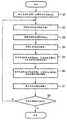
图1是本实施方式的超声波诊断装置1的结构框图。FIG. 1 is a block diagram showing the configuration of an ultrasonic diagnostic apparatus 1 according to the present embodiment.
图2是示出按照本穿刺术辅助功能的处理(穿刺术辅助处理)的流程的流程图。FIG. 2 is a flowchart showing the flow of processing (puncture assistance processing) according to the puncture assistance function.
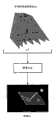
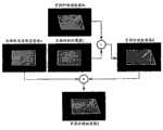
图3是概念性地表示图2的步骤S2~S7的处理的图。FIG. 3 is a diagram conceptually showing the processing of steps S2 to S7 in FIG. 2 .
图4是示出使用了一维阵列探头时的透镜方向的波束宽度的一个例子的图。FIG. 4 is a diagram showing an example of the beam width in the lens direction when a one-dimensional array probe is used.
图5是示出使用了二维阵列探头时的透镜方向的波束宽度的一个例子的图。FIG. 5 is a diagram showing an example of the beam width in the lens direction when a two-dimensional array probe is used.
图6是用于说明变形例2的步骤S3的处理的图。FIG. 6 is a diagram for explaining the processing of step S3 of Modification 2. FIG.
图7是用于说明变形例2的步骤S4的处理的图。FIG. 7 is a diagram for explaining the processing of step S4 of Modification 2. FIG.
图8是用于说明变形例3的步骤S3的处理的图。FIG. 8 is a diagram for explaining the processing of step S3 of Modification 3. FIG.
图9是用于说明变形例4的步骤S4的处理的图。FIG. 9 is a diagram for explaining the processing of step S4 of
图10是用于说明本实施方式的超声波诊断装置的效果的图。FIG. 10 is a diagram for explaining the effects of the ultrasonic diagnostic apparatus according to this embodiment.
图11是概念性地示出第2实施方式的穿刺术辅助处理的图。Fig. 11 is a diagram conceptually showing puncture assistance processing in the second embodiment.
图12是概念性地示出第2实施方式的变形例1的穿刺术辅助处理的图。FIG. 12 is a diagram conceptually showing puncture assistance treatment in Modification 1 of the second embodiment.
图13是概念性地示出第2实施方式的变形例2的穿刺术辅助处理的图。FIG. 13 is a diagram conceptually showing puncture assistance processing according to Modification 2 of the second embodiment.
图14是用于说明以往的超声波诊断装置中的处理的图。FIG. 14 is a diagram for explaining processing in a conventional ultrasonic diagnostic apparatus.
符号说明Symbol Description
1…超声波诊断装置、12…超声波探头、13…输入装置、14…监视器、21…超声波发送单元、22…超声波接收单元、23…B模式处理单元、24…多普勒处理单元、26…剖面自动检测单元、28…图像生成单元、29…图像合成单元、29…控制处理器(CPU)、33…存储单元、35…接口单元1...Ultrasonic diagnostic device, 12...Ultrasonic probe, 13...Input device, 14...Monitor, 21...Ultrasonic sending unit, 22...Ultrasonic receiving unit, 23...B mode processing unit, 24...Doppler processing unit, 26... Section automatic detection unit, 28...image generation unit, 29...image synthesis unit, 29...control processor (CPU), 33...storage unit, 35...interface unit
具体实施方式Detailed ways
以下,参照附图说明实施方式。另外,在以下的说明中,针对具有大致相同的功能以及结构的结构要素,添加同一符号,重复说明只在必要时进行。Embodiments will be described below with reference to the drawings. In addition, in the following description, the same code|symbol is attached|subjected to the structural element which has substantially the same function and structure, and repeated description is performed only when necessary.
图1是示出本实施方式的超声波诊断装置1的结构框图。如该图所示,本超声波诊断装置1具备超声波探头12、输入装置13、监视器14、超声波发送单元21、超声波接收单元22、B模式处理单元23、多普勒处理单元24、原始数据存储器25、体数据生成单元26、图像处理单元28、显示处理单元30、控制处理器(CPU)31、穿刺术辅助图像生成单元32、存储单元33、接口单元35。以下,针对各个结构要素的功能进行说明。FIG. 1 is a block diagram showing the configuration of an ultrasonic diagnostic apparatus 1 according to the present embodiment. As shown in the figure, the ultrasonic diagnostic apparatus 1 includes an
超声波探头12是对被检体发送超声波,接收基于该发送的超声波的来自被检体的反射波的设备(探针),在其前端具有排列多个的压电振子、匹配层、背衬材料等。压电振子根据来自超声波发送单元21的驱动信号向扫描区域内的所希望的方向发送超声波,并将来自该被检体的反射波转换成电信号。匹配层是设置于该压电振子,用于使超声波能量高效地传播的中间层。背衬材料防止超声波从该压电振子向后方传播。如果从该超声波探头12向被检体P发送超声波,则该发送超声波被体内组织的声阻抗的不连续面依次反射,作为回波信号被超声波探头12接收。该回波信号的振幅依存于成为反射的不连续面中的声阻抗的差。另外,所发送的超声波脉冲被正在移动的血流反射时的回波由于多普勒效应而依存于移动体的超声波发送接收方向的速度分量,并受到频移。另外,以本实施方式的超声波探头12使用超声波阵子沿着规定的方向排列的一维超声波探头的情况为例。The
输入装置13与装置主体11连接,具有用于将来自操作者的各种指示、条件、关注区域(ROI)的设定指示、各种画质条件设定指示等取入装置主体11的各种开关、按钮、轨迹球、鼠标、键盘等。另外,输入装置13具有在后述的管腔附近血流描绘功能中,用于输入诊断部位的专用开关、用于控制影像化中所使用的彩色数据的范围的专用旋钮、用于控制体素(voxel)的透明度(不透明度)的专用旋钮等。The
监视器14根据来自显示处理单元30的视频信号,将生物体内的形态学信息、或血流信息显示为图像。The
超声波发送单元21具有未图示的触发发生电路、延迟电路以及脉冲发生器电路等。在触发发生电路中,以规定的等级频率fr Hz(周期:1/fr秒),重复发生用于形成发送超声波的触发脉冲。另外,在延迟电路中,对各触发脉冲赋予在每个通道中将超声波会聚成束状并确定发送指向性所需的延迟时间。脉冲发生器电路以基于该触发脉冲的定时,对探头12施加驱动脉冲。The
超声波接收单元22具有未图示的放大器电路、A/D转换器、延迟电路、加法器等。在放大器电路中,在每个通道中将经由探头12取入的回波信号进行放大。在A/D转换器中,将放大后的模拟的回波信号转换成数字回波信号。在延迟电路中,对数字转换后的回波信号确定接收指向性,赋予进行接收动态聚焦所需的延迟时间,之后,在加法器进行加法处理。通过该加法,强调来自与回波信号的接收指向性对应的方向的反射分量,根据接收指向性和发送指向性形成超声波发送接收的综合的波束。The
B模式处理单元23从接收单元22接收回波信号,实施对数放大、包络线检波处理等,生成信号强度按照亮度的明暗表现的数据。The B-
多普勒处理单元24根据从接收单元22接收到的回波信号提取血流信号,生成血流数据。血流的提取通常由CFM(Color FlowMapping,彩色血流映射)来进行。此时,对血流信号进行分析,作为血流数据针对多点求平均速度、方差、能量等血流信息。The
原始数据存储器25使用从B模式处理单元23接收到的多个B模式数据,生成作为三维的超声波扫描线上的B模式数据的B模式原始数据。另外,原始数据存储器25使用从多普勒处理单元24接收到的多个血流数据,生成作为三维的超声波扫描线上的血流数据的血流原始数据。另外,也可以以噪音降低或使图像的连接优良为目的,在原始数据存储器25之后插入三维的滤波器,进行空间平滑处理。The
体数据生成单元26通过执行RAW-体素转换,从而根据从原始数据存储器25接收到的B模式原始数据,生成B模式体数据血流体数据。The volume
图像处理单元28对于从体数据生成单元26接收的体数据,进行体绘制、多剖面转换显示(MPR:multi planar reconstruction,多平面重构)、最大值投影显示(MIP:maximum intensity projection,最大强度投影)等规定的图像处理。另外,以噪音减少或使图像的连接优良为目的,也可以在图像处理单元28之后插入二维的滤波器,进行空间平滑处理。The
显示处理单元30对于在图像处理单元28中生成·处理的各种图像数据执行动态范围、亮度(明亮度)、对比度、γ曲线校正、RGB转换等各种处理。The
控制处理器31具有作为信息处理装置(计算机)的功能,控制本超声波诊断装置主体的动作。控制处理器31从存储单元33读出用于实现后述的穿刺术辅助功能的专用程序在自身所具有的存储器上展开,执行与各种处理相关的运算·控制等。The
穿刺术辅助图像生成单元32根据后述的穿刺术辅助功能,生成用于辅助穿刺术的图像。The puncture assistance
存储单元33保存有用于实现后述的穿刺术辅助功能的专用程序、诊断信息(患者ID、医师的意见等)、诊断协议、发送接收条件、用于实现散斑除去功能的程序、体部标记生成程序、对每个诊断部位预先设定影像化中使用的彩色数据的范围的转换表、其它的数据组。另外,根据需要,还用于未图示的图像存储器中的图像的保管等。存储单元33的数据还能够经由接口单元35向外围装置转送。The
接口单元35是与输入装置13、网络、新的外部存储装置(未图示)相关的接口。由该装置得到的超声波图像等数据或分析结果等能够通过接口单元32,经由网络向其它的装置转送。The
(穿刺术辅助功能)(Auxiliary function for puncture)
接着,针对本超声波诊断装置1所具有的穿刺术辅助功能进行说明。该功能在使用超声波诊断装置一边监视生物体组织以及穿刺针一边进行穿刺术的情况下,一边以不会远离穿刺针的方式设定基于超声波的被扫描区域,一边生成并提供始终良好地对生物体组织和穿刺针进行影像化得到的穿刺术辅助图像。Next, the puncture assisting function of the ultrasonic diagnostic apparatus 1 will be described. This function is used to generate and provide always good biopsy while setting the scanned area based on ultrasound so that the ultrasonic diagnostic device monitors the biological tissue and the puncture needle while performing puncture. Auxiliary puncture images obtained by imaging body tissues and puncture needles.
图2是表示按照本穿刺术辅助功能的处理(穿刺术辅助处理)的流程的流程图。以下,针对在该流程图所示的各步骤中执行的处理的内容进行说明。FIG. 2 is a flowchart showing the flow of processing (puncture assistance processing) according to the puncture assistance function. Hereinafter, the content of processing executed in each step shown in this flowchart will be described.
[患者信息等的输入、穿刺术辅助模式的选择:步骤S1][Input of patient information, etc., selection of puncture assistance mode: Step S1]
经由操作单元33执行患者信息、检查信息等的输入、执行本穿刺术辅助功能的穿刺术辅助模式的选择(步骤S1)。被输入、选择的各种信息自动地存储于存储装置29。另外,控制单元31响应穿刺术辅助模式的选择操作,启动用于执行穿刺术辅助功能的程序。Input of patient information, examination information, etc., and selection of a puncture assistance mode for performing this puncture assistance function are performed via the operation unit 33 (step S1 ). Various types of information input and selected are automatically stored in the storage device 29 . In addition, the
[生物体高清晰度图像A的取得:步骤S2][Acquisition of biological high-resolution image A: step S2]
接着,执行组织谐波成像等、良好地描绘生物体组织的成像法或者以发送接收设定执行超声波发送接收,取得以高清晰度对生物体组织进行影像化得到的生物体高清晰度图像A(步骤S2)。另外,生物体高清晰度图像A并不限定于由组织谐波成像摄像得到的图像,也可以是使用在频带中包含基波分量的接收信号而摄像得到的图像。另外,根据需要,也可以执行使用了涵盖多个帧(多个容积)的超声波数据的加法处理、差分处理、最大值投影处理、最小值投影处理、平均化处理中的至少一个,生成生物体高清晰度图像A。涵盖该多个帧(多个容积)的超声波图像也同样可以使用通过组织谐波成像摄像得到的图像,也可以使用在频带中包含基波分量而摄像得到的图像。Next, an imaging method such as tissue harmonic imaging is performed to describe the living tissue well, or ultrasonic transmission and reception are performed with transmission and reception settings, and a living body high-resolution image A ( Step S2). In addition, the biological high-resolution image A is not limited to an image captured by tissue harmonic imaging, but may be an image captured using a received signal including a fundamental wave component in a frequency band. In addition, if necessary, at least one of addition processing, difference processing, maximum value projection processing, minimum value projection processing, and averaging processing using ultrasound data covering a plurality of frames (multiple volumes) may be performed to generate a living body height Clarity image A. Ultrasonic images covering the plurality of frames (multiple volumes) may similarly be images obtained by tissue harmonic imaging or images obtained by including the fundamental wave component in the frequency band.
另外,作为组织谐波成像的摄像方法,也可以使用脉冲减法(将极性或者相位不同的多个脉冲相加而得到高谐波带宽的接收数据的方法)。并不特别地限定于此时的脉冲加法数,也可以使用任意的脉冲数。In addition, as an imaging method for tissue harmonic imaging, pulse subtraction (a method of adding a plurality of pulses with different polarities or phases to obtain received data with a high harmonic bandwidth) may also be used. The number of pulses added here is not particularly limited, and any number of pulses may be used.
另外,也可以执行脉冲减法而取得涵盖多个帧(多个容积)的超声波数据,执行使用这些数据的加法处理、差分处理,生成生物体高清晰度图像A。In addition, pulse subtraction may be performed to obtain ultrasonic data covering multiple frames (multiple volumes), and addition processing and difference processing using these data may be performed to generate the living body high-resolution image A.
[取得穿刺针强调图像B:步骤S3][Acquisition of puncture needle emphasized image B: Step S3]
接着,通过使用比较低的频率的发送波形,在影像化中使用接收信号中发送波形的频率的基波分量等,尽可能抑制发送时以及接收时的光栅波瓣,且执行将发送接收方向实质上设为与针的长度方向的垂直方向的倾斜扫描,来取得穿刺针强调图像B(步骤S3)。Next, by using a relatively low-frequency transmission waveform, the fundamental wave component of the frequency of the transmission waveform in the received signal is used for visualization, and the grating lobes at the time of transmission and reception are suppressed as much as possible, and the transmission and reception directions are substantially changed. Oblique scanning in a direction perpendicular to the longitudinal direction of the needle is used to acquire the puncture needle-enhanced image B (step S3 ).
另外,发送接收设定并不拘泥于上述内容,例如,能够使用所使用的超声波探头12的超声波振子的元件间距、超声波阵子的发送接收频率特性、倾斜角度等中的至少一个来控制发送接收条件。特别地,理论上知道为了不出现光栅波瓣,满足以下的式子即可。In addition, the transmission and reception settings are not limited to the above-mentioned content, for example, the transmission and reception conditions can be controlled using at least one of the element pitch of the ultrasonic transducers of the
d<λ/(1+sinθM) (1)d<λ/(1+sinθM ) (1)
在此,d、λ、θM分别是元件间距[mm]、波长[mm]、主瓣的扫描角度(倾斜角度、方位角度)[rad.]。在本步骤S3中,为了满足条件式(1),控制处理器31通过自动地、或者来自输入装置13的手动输入来设定发送波形的波长(或者频率)以及接收中心频率、接收频带。然而,还有时不存在满足条件式(1)的发送接收条件。此时,优选以条件式(1)等为基准,选择光栅波瓣尽可能不进入图像内的条件。Here, d, λ, and θM are element pitch [mm], wavelength [mm], and scanning angle (tilt angle, azimuth angle) of the main lobe [rad.], respectively. In this step S3 , in order to satisfy the conditional expression (1), the
优选倾斜角度被设定为,以垂直或者接近垂直的角度向穿刺针发送超声波波束。当使用穿刺适配器时,能够通过在超声波诊断装置中注册以适配器为基准的穿刺针的角度,从而能够在超声波图像上显示穿刺针的导线。此时,控制处理器31根据所注册的穿刺针的角度,自动地确定倾斜角度。当通过位置传感器检测穿刺针的位置或方向时,控制处理器31根据由该位置传感器检测的位置等自动地确定倾斜角度。另外,当没有使用基于穿刺适配器的穿刺针角度的注册或位置传感器等时,例如,也可以使用一般的边缘检测方法或线段检测方法等检测超声波图像上的穿刺针,将该穿刺针的方向作为基准自动地确定倾斜角度。另外,也可以将超声波图像上的穿刺针的方向作为基准,通过来自输入装置13的手动输入来设定、调整倾斜角度。Preferably, the inclination angle is set so that the ultrasonic beam is sent to the puncture needle at a vertical or nearly vertical angle. When the puncture adapter is used, the guide wire of the puncture needle can be displayed on the ultrasonic image by registering the angle of the puncture needle based on the adapter in the ultrasonic diagnostic apparatus. At this time, the
[取得生物体组织图像C:步骤S4][Acquisition of biological tissue image C: step S4]
接着,设主瓣的扫描角度为0,执行扫描角度以外的发送接收条件与取得穿刺针强调图像B时的条件(即,在步骤S3中设定的发送接收条件)实质上相同的超声波发送接收,制成生物体组织图像C(步骤S4)。Next, assume that the scanning angle of the main lobe is 0, and perform ultrasonic transmission and reception with the transmission and reception conditions other than the scanning angle substantially the same as the conditions when acquiring the puncture needle-enhanced image B (that is, the transmission and reception conditions set in step S3). , to create a biological tissue image C (step S4).
另外,步骤S3和步骤S4的执行顺序能够根据需要来更换。另外,步骤S3中的超声波扫描区域和步骤S4中的超声波扫描区域不需要相同。即,在步骤S3中,以与强调穿刺针而进行影像化的目的相符的方式设定超声波扫描区域即可,另一方面,在步骤S4中,以与抵消穿刺针强调图像B所包含的组织的目的相符的方式(例如,以至少包含穿刺针强调图像B所包含的组织区域的方式)设定超声波扫描区域即可。In addition, the execution order of step S3 and step S4 can be changed as needed. In addition, the ultrasonic scanning area in step S3 and the ultrasonic scanning area in step S4 do not need to be the same. That is, in step S3, it is only necessary to set the ultrasonic scanning area so as to match the purpose of emphasizing the puncture needle to visualize it; It is sufficient to set the ultrasonic scanning area in a manner that matches the purpose (for example, so as to include at least the tissue area included in the puncture needle-emphasized image B).
[使用图像B、图像C生成穿刺针提取图像D:步骤S5][Using image B and image C to generate puncture needle extraction image D: step S5]
接着,穿刺术辅助图像生成单元32通过使用了穿刺针强调图像B和生物体组织图像C的图像处理,生成穿刺针提取图像D(步骤S5)。例如,穿刺术辅助图像生成单元32将穿刺针强调图像B的亮度值和生物体组织图像C的亮度值在空间上对应的每个位置进行比较,当生物体组织图像C的亮度值大时,将0分配给各位置的每一个,当穿刺针强调图像B的亮度值大时,将图像B的亮度值分配给各位置的每一个,从而生成穿刺针提取图像D。由此,对与穿刺针提取图像D上的穿刺针对应的位置分配穿刺针强调图像B所包含的穿刺针的亮度值,另一方面,对穿刺针提取图像D上的穿刺针以外的区域分配亮度值0。从而,穿刺针提取图像D是提取穿刺针良好地影像化得到的图像。Next, the puncture assisting
另外,穿刺针提取图像D的生成方法并不限定于上述那样的亮度值的比较。例如,也可以执行将穿刺针强调图像B的亮度值和生物体组织图像C的亮度值在空间上对应的每个位置进行平均化、或者加减法处理(加法处理、差分处理)等,将得到的值作为各位置的亮度值来分配,从而生成穿刺针提取图像D。In addition, the method of generating the extracted puncture needle image D is not limited to the comparison of brightness values as described above. For example, it is also possible to average each position corresponding to the luminance value of the puncture needle emphasized image B and the luminance value of the biological tissue image C in space, or perform addition and subtraction processing (addition processing, difference processing), etc. to convert The obtained value is distributed as the brightness value of each position, and the puncture needle extraction image D is generated.
另外,作为生成穿刺针提取图像D的前处理,例如,为了强调(或者抑制)穿刺针或者生物体组织,也可以针对穿刺针强调图像B以及生物体组织图像C的至少一方,调整增益以及动态范围的至少一方。在穿刺针等硬化的物质与生物体组织之间,声阻抗的差非常大。因此,来自穿刺针的反射信号与生物体组织的反射信号相比非常大,在穿刺针强调图像B中,与周围的生物体组织相比较,穿刺针以高亮度显示。从而,例如,通过使穿刺针强调图像B的增益低于生物体组织图像C,或者以穿刺针强调图像B的组织和生物体组织图像C的组织成为相同的程度的明暗的方式进行增益校正,从而,能够使生成穿刺针提取图像D时与生物体组织对应的位置的亮度为0。其结果,在穿刺针提取图像D的生成中能够有效地提取与高亮度区域对应的穿刺针。In addition, as a pre-processing for generating the puncture needle extraction image D, for example, in order to emphasize (or suppress) the puncture needle or the biological tissue, at least one of the puncture needle emphasis image B and the biological tissue image C may be adjusted for gain and dynamics. at least one side of the range. There is a very large difference in acoustic impedance between a hardened substance such as a puncture needle and living tissue. Therefore, the reflection signal from the puncture needle is much larger than the reflection signal of the living tissue, and in the puncture needle-enhanced image B, the puncture needle is displayed with higher brightness than the surrounding living tissue. Therefore, for example, by making the gain of the puncture needle-emphasized image B lower than that of the biological tissue image C, or performing gain correction so that the tissue of the puncture-needle-emphasized image B and the tissue of the biological tissue image C have the same brightness and darkness, Therefore, it is possible to set the luminance of the position corresponding to the living tissue to 0 when the puncture needle extraction image D is generated. As a result, in generating the puncture needle extraction image D, the puncture needle corresponding to the high-brightness region can be efficiently extracted.
[使用生物体高清晰度图像A、穿刺针提取图像D来生成·显示穿刺术辅助图像E:步骤S6、S7][Generation and display of puncture auxiliary image E using biological high-resolution image A and puncture needle extraction image D: Steps S6 and S7]
接着,穿刺术辅助图像生成单元32使用良好地对穿刺针进行影像化得到的穿刺针提取图像D和以高清晰度对生物体组织进行影像化得到的生物体高清晰度图像A,生成穿刺术辅助图像E(步骤S6)。具体而言,穿刺术辅助图像生成单元32将只有生物体以高清晰度来影像化的生物体高清晰度图像A的亮度值和提取出穿刺针的穿刺针提取图像D的亮度值在空间上对应的每个位置进行比较,在各位置分配较大的亮度值,从而生成穿刺术辅助图像E。由此,穿刺术辅助图像E成为在良好的画质的生物体高清晰度图像A上重叠高亮度的针图像来显示的图像。另外,也可以通过执行使用了穿刺针提取图像D和生物体高清晰度图像A的加法处理、差分处理、最大值投影处理、最小值投影处理、平均化处理中的至少一个,来生成穿刺术辅助图像E。Next, the puncture assistance
穿刺术辅助图像E的生成方法并不限定于上述那样的亮度值的比较。例如,也可以通过执行将穿刺针提取图像D的亮度值和生物体高清晰度图像A的亮度值在空间上对应的每个位置进行平均化、加减法处理等,将得到的值作为各位置的亮度值来分配,从而生成穿刺术辅助图像E。另外,在制成穿刺术辅助图像E之前,也可以针对穿刺针提取图像D以及生物体高清晰度图像A中的至少一方,对增益以及动态范围的至少一方进行调整。例如,优选穿刺针提取图像D只显示高亮度的针。然而,假设实际上在步骤S5中生成的穿刺针提取图像D中,会残留不少的生物体组织像。此时,例如能够通过缩小穿刺针提取图像D的动态范围来抑制或者除去来自组织区域的信号,通过提高增益来使与穿刺针对应的区域以高亮度发光。另外,该增益、动态范围的调整能够生成与穿刺针提取图像D的亮度相关的直方图,通过使用了所生成的直方图的阈值处理等自动地、或者通过来自输入装置13的手动操作手动地执行。The method of generating the puncture assistance image E is not limited to the comparison of brightness values as described above. For example, it is also possible to perform averaging, addition and subtraction processing, etc. for each position corresponding to the brightness value of the puncture needle extraction image D and the brightness value of the living body high-resolution image A in space, and use the obtained value as each position The luminance value is assigned to generate the puncture auxiliary image E. In addition, at least one of the gain and the dynamic range may be adjusted for at least one of the puncture needle extraction image D and the living body high-resolution image A before creating the puncture auxiliary image E. For example, it is preferable that the puncture needle extraction image D only display high-brightness needles. However, it is assumed that a lot of living tissue images remain in the puncture needle extraction image D generated in step S5 actually. In this case, for example, by reducing the dynamic range of the puncture needle extraction image D, the signal from the tissue region can be suppressed or removed, and by increasing the gain, the region corresponding to the puncture needle can be illuminated with high brightness. In addition, the adjustment of the gain and the dynamic range can generate a histogram related to the brightness of the puncture needle extraction image D, and can be performed automatically by threshold processing using the generated histogram or manually by a manual operation from the
[穿刺术中的穿刺术辅助图像生成·显示的重复:步骤S8][Repetition of generation and display of puncture-assisted images during puncture: step S8]
在穿刺术中依次重复执行上述的步骤S2~S7的处理。During the puncture, the above-described processes of steps S2 to S7 are sequentially and repeatedly executed.
图3是概念性地表示图2的步骤S2~S7的处理的图。如该图所示,执行与步骤S2~S7的各个对应的各处理,穿刺术辅助图像E被依次更新显示为最新的图像。手术者能够通过观察实时显示的穿刺术辅助图像E,来容易地识别生物体组织与穿刺针的相对位置关系。FIG. 3 is a diagram conceptually showing the processing of steps S2 to S7 in FIG. 2 . As shown in the figure, each process corresponding to each of steps S2 to S7 is executed, and the puncture assistance image E is sequentially updated and displayed as the latest image. The operator can easily recognize the relative positional relationship between the living tissue and the puncture needle by observing the puncture assistance image E displayed in real time.
(变形例1)(Modification 1)
在上述实施方式中,将超声波探头12是一维阵列探头的情况作为例子。对此,作为超声波探头12也可以采用1.5维阵列探头或者二维阵列探头。由此,与使用一维阵列探头时的透镜方向(切片方向)的波束宽度(参照图4)相比较,能够使使用二维阵列探头时的透镜方向的波束宽度(参照图5)变厚,而对穿刺针强调图像组Bn、生物体组织图像C进行摄像。其结果,即使在穿刺针的位置从超声波探头12的正下方稍微偏移的情况下,也能够始终使穿刺针最优地影像化。In the above-described embodiments, the case where the
另外,如果以对穿刺针进行影像化为目的,则认为在生物体组织图像C的摄像中,不需要使透镜方向的波束变厚。然而,如果不尽可能使穿刺针强调图像组Bn与生物体组织图像C的生物体组织区域的空间分辨率相同,则当制成穿刺针提取图像D时会大量地残留生物体组织。从该观点来看,当在穿刺针强调图像组Bn的摄像中使透镜方向的波束宽度变厚时,希望在生物体组织图像C的摄像也相同地使透镜方向的波束宽度变厚(与穿刺针强调图像组Bn的摄像中的波束宽度相同)。In addition, if the purpose is to visualize the puncture needle, it is considered that it is not necessary to thicken the beam in the direction of the lens in imaging the biological tissue image C. However, if the spatial resolution of the living tissue region of the puncture needle-enhanced image group Bn is not equal to that of the living tissue image C as much as possible, a large amount of living tissue will remain when the puncture needle extraction image D is created. From this point of view, when the beam width in the lens direction is increased in imaging of the puncture needle-enhanced image group Bn, it is desirable to increase the beam width in the lens direction in the imaging of the biological tissue image C similarly (similar to the puncture The beam widths in the imaging of the highlighted image group Bn are the same).
(变形例2)(Modification 2)
作为超声波探头12,当使用二维阵列探头时,也可以如下那样进行步骤S3、S4、S5的处理。即,在步骤S3的处理中,如图6所示,通过与切片方向平行的n个倾斜扫描取得穿刺针强调图像组Bn,在空间上对应的每个位置执行亮度值的平均处理、或者加减法处理等,来生成图像Ba。另外,在步骤S4的处理中,如图7所示,通过与切片方向平行的n个通常扫描取得生物体组织图像组Cn,在空间上对应的每个位置执行亮度值的平均处理、或者加减法处理等,生成图像Ca。可以通过使用这样得到的图像Ba、图像Ca,在步骤S5中进行已述的亮度值比较处理等,从而生成穿刺针提取图像D。When a two-dimensional array probe is used as the
另外,当生成图像Ba时,通过根据距各图像的超声波探头12正下方的距离,对进行平均计算、或者加法处理等时的加权进行调整,从而能够识别穿刺针从超声波探头12的正下方偏离多少。例如,通过随着远离超声波探头12的正下方而减少加权,从而当穿刺针远离超声波探头12的正下方时,将穿刺术辅助图像E的穿刺针以低的(暗的)亮度显示,另一方面,当穿刺针存在于超声波探头12的正下方时,穿刺术辅助图像E的穿刺针以高的(明亮的)亮度来显示。手术者能够以在穿刺术辅助图像E上显示的穿刺针的亮度为基准,容易地掌握超声波探头12(以及扫描区域)与穿刺针的位置关系。In addition, when generating the image Ba, by adjusting the weighting when performing average calculation or addition processing according to the distance from directly below the
(变形例3)(Modification 3)
作为超声波探头12通过使用机械四维探头(通过使一维振子阵列摇动,从而能够随着时间变化对三维区域进行扫描的探头),从而与上述变形例2相同,可以如以下那样进行步骤S3、S4、S5的处理。即,在步骤S3的处理中,如图8所示,通过一边使扫描剖面沿着切片方向摆动的方式移动(摆动)一边执行倾斜扫描,从而取得与n个扫描剖面对应的穿刺针强调图像组Bn,在空间上对应的每个位置执行亮度值的平均处理、或者加减法处理等,生成图像Ba。另外,在步骤S4的处理中,如图9所示,通过一边使扫描剖面沿着切片方向摆动的方式移动(摆动)一边执行通常的扫描,从而取得与n个扫描剖面对应的生物体组织图像组Cn,在空间上对应的每个位置执行亮度值的平均处理、或者加减法处理等,生成图像Ca。通过使用这样得到的图像Ba、图像Ca,在步骤S5中进行已述的亮度值比较处理等,从而生成穿刺针提取图像D。当然,还能够进行与变形例2相同的加权处理。By using a mechanical four-dimensional probe (a probe capable of scanning a three-dimensional region over time by shaking a one-dimensional vibrator array) as the
根据以上所述的超声波诊断装置,当一边监视生物体组织以及穿刺针一边进行穿刺术时,如图10所示,使用以不会远离穿刺针的方式设定的被扫描区域通过倾斜扫描取得穿刺针强调图像,同时通过与穿刺针强调图像相比只有发送接收方向不同的通常扫描来取得生物体组织图像,使用穿刺针强调图像以及生物体组织图像,生成穿刺针提取图像。穿刺针强调图像和生物体组织图像除了发送接收方向以外,实质上是以同一发送接收条件取得的图像,因此,能够使用两者生成恰当地除去生物体组织并提取出穿刺针的穿刺针提取图像。使用这样得到的穿刺针提取图像和通过组织谐波成像等得到的生物体高清晰度图像,生成并显示包含以高清晰度影像化的生物体组织和恰当地提取出的穿刺针的穿刺术辅助图像。手术者能够通过观察始终良好地对穿刺针和生物体组织进行影像化得到的穿刺术辅助图像,从而不依赖于感觉而安全且可靠地执行穿刺术。According to the ultrasonic diagnostic apparatus described above, when puncture is performed while monitoring the living tissue and the puncture needle, as shown in FIG. The needle-enhanced image obtains a living tissue image by normal scanning in which only the transmission and reception directions are different from the needle-enhanced image, and the needle-enhanced image and the living tissue image are used to generate a needle-extracted image. The puncture needle-enhanced image and the living tissue image are acquired under substantially the same transmission and reception conditions except for the transmission and reception directions, so both can be used to generate a puncture needle extraction image in which the living tissue is properly removed and the puncture needle is extracted . Using the puncture needle extraction image obtained in this way and the biological high-resolution image obtained by tissue harmonic imaging, etc., a puncture assistance image including living tissue visualized in high-resolution and an appropriately extracted puncture needle is generated and displayed . The operator can perform the puncture safely and reliably without depending on the feeling by observing the puncture assisting image obtained by visualizing the puncture needle and the living tissue consistently well.
(第2实施方式)(Second embodiment)
接下来,针对第2实施方式的超声波诊断装置进行说明。本实施方式的超声波诊断装置1取得与多个倾斜角的每一个对应的穿刺针强调图像B(或者,穿刺针强调图像组Bn。以下,以穿刺针强调图像B为例),根据被刺入被检体的穿刺针的角度选择与最适合穿刺针的影像化的倾斜角对应的穿刺针强调图像B,使用该图像生成穿刺针提取图像D。Next, an ultrasonic diagnostic apparatus according to a second embodiment will be described. Ultrasonic diagnostic apparatus 1 according to the present embodiment acquires a puncture needle-enhanced image B corresponding to each of a plurality of inclination angles (or a puncture-needle-enhanced image group Bn. Hereinafter, the puncture needle-enhanced image B is taken as an example), and according to the For the angle of the puncture needle of the subject, the puncture needle-enhanced image B corresponding to the inclination angle most suitable for visualization of the puncture needle is selected, and the puncture needle extraction image D is generated using this image.
另外,当对本实施方式的穿刺术辅助处理和第1实施方式的穿刺术辅助处理进行比较时,图2的步骤S3、步骤S5的处理不同。以下,以本实施方式的步骤S3、步骤S5为中心进行说明。In addition, when the puncture auxiliary process of the present embodiment is compared with the puncture auxiliary process of the first embodiment, the processes of step S3 and step S5 in FIG. 2 are different. Hereinafter, step S3 and step S5 of this embodiment will be mainly described.
图11是概念性地示出第2实施方式的穿刺术辅助处理的图(该图中的步骤编号与图2所示的步骤编号对应)。如该图所示,在步骤S3中,取得多个倾斜角的每一个对应的穿刺针强调图像B。多个倾斜角能够任意地设定。在本实施方式中,例如,假设采用α1=15°、α2=30°、α3=45°这3个倾斜角。另外,各倾斜角的发送接收设定与第1实施方式相同。FIG. 11 is a diagram conceptually showing puncture assistance processing according to the second embodiment (the step numbers in the diagram correspond to the step numbers shown in FIG. 2 ). As shown in the figure, in step S3, the puncture needle-enhanced image B corresponding to each of the plurality of inclination angles is acquired. A plurality of inclination angles can be set arbitrarily. In this embodiment, for example, it is assumed that three inclination angles of α1=15°, α2=30°, and α3=45° are employed. In addition, the transmission and reception setting of each inclination angle is the same as that of the first embodiment.
同样地,在步骤S3中,控制处理器31检测穿刺针对于被检体的刺入角度β。该穿刺针的刺入角度β的检测例如能够通过使用多个穿刺针强调图像B的至少一个进行线段检测处理等来实现。另外,例如,也可以通过设置于穿刺针适配器的检测器来检测刺入角度。另外,控制处理器31根据检测到的穿刺针的刺入角度β,从与多个倾斜角对应的多个穿刺针强调图像B中,选择穿刺针强调图像D的生成中使用的穿刺针强调图像B。Likewise, in step S3, the
在步骤S5中,穿刺术辅助图像生成单元32通过使用了被选择的穿刺针强调图像B和生物体组织图像C的图像处理,生成穿刺针提取图像D。图像处理的具体的内容与第1实施方式相同。In step S5 , puncture assisting
另外,随着穿刺术的进行,依次重复执行步骤S2~S7的处理(或者,步骤S3~S7的处理)。从而,希望控制处理器31根据在步骤S3中检测的穿刺针的角度以及其时间变化,控制多个倾斜角以及倾斜角的数量(倾斜方向数)中的至少一方。此时,发送接收条件根据所确定的多个倾斜角以及倾斜角的数量被确定并控制。In addition, the processes of steps S2 to S7 (or the processes of steps S3 to S7 ) are sequentially and repeatedly executed as the puncture proceeds. Therefore, it is desirable that the
(变形例1)(Modification 1)
在上述实施方式中,例如,假设倾斜角为α1=15°、α2=30°、α3=45°。对此,例如,如图12所示,在步骤S3中执行设倾斜角α0=0的扫描。设该倾斜角α0=0而得到的穿刺针强调图像B与在第1实施方式中取得的生物体组织图像C等价。从而,能够通过在步骤S3中执行还包含倾斜角α0=0的多个穿刺针强调图像B的取得处理,从而省略步骤S4中的生物体组织图像C的取得处理。In the above-described embodiment, for example, it is assumed that the inclination angles are α1=15°, α2=30°, and α3=45°. In this regard, for example, as shown in FIG. 12 , in step S3 , scanning with the inclination angle α0=0 is performed. The puncture needle-enhanced image B obtained by assuming the inclination angle α0=0 is equivalent to the living tissue image C obtained in the first embodiment. Therefore, the acquisition process of the biological tissue image C in step S4 can be omitted by executing the acquisition process of a plurality of puncture needle enhanced images B including the inclination angle α0=0 in step S3 .
(变形例2)(Modification 2)
如上述本实施方式的变形例1那样,当在步骤S3中执行设倾斜角α0=0的扫描时,例如,如图13所示,也可以在进行与该倾斜角α0=0对应的穿刺针强调图像B和与其它的倾斜角对应的穿刺针强调图像B的图像处理之后,检测穿刺针的刺入角度β,选择穿刺针强调图像D的生成所使用的穿刺针强调图像B。As in Modification 1 of the present embodiment described above, when the scan with the inclination angle α0=0 is executed in step S3, for example, as shown in FIG. After image processing of the enhanced image B and the puncture needle-emphasized image B corresponding to other inclination angles, the puncture needle penetration angle β is detected, and the puncture-needle-emphasized image B used for generation of the puncture-needle-emphasized image D is selected.
一般而言,刺入被检体的穿刺针的角度根据每个手术而不同。根据本实施方式的超声波诊断装置,能够取得与多个倾斜角的每一个对应的穿刺针强调图像B,根据刺入被检体的穿刺针的角度,选择与最适合于穿刺针的影像化的倾斜角对应的穿刺针强调图像B,使用该图像生成穿刺针提取图像D、穿刺术辅助图像E。从而,在穿刺术中,能够始终使穿刺针恰当地进行影像化,能够为穿刺术的安全性以及质量的提高作出贡献。In general, the angle of the puncture needle piercing the subject differs for each operation. According to the ultrasonic diagnostic apparatus of this embodiment, it is possible to obtain the puncture needle enhanced image B corresponding to each of a plurality of inclination angles, and to select the most suitable image for the puncture needle according to the angle of the puncture needle inserted into the subject. The puncture needle emphasis image B corresponding to the inclination angle is used to generate the puncture needle extraction image D and the puncture auxiliary image E. Therefore, in the puncture operation, the puncture needle can always be properly imaged, and can contribute to the improvement of the safety and quality of the puncture operation.
另外,在第2实施例以及其变形例中,从多个倾斜图像中选择与最合适的倾斜角度对应的穿刺针强调图像B,但例如,也可以将多个倾斜图像的最大值投影图像作为穿刺针强调图像B来使用。关于穿刺角度检测,假设当其精度低时,无法选择最合适的穿刺针强调图像,因此,能够不进行检测而进行最大值投影,从而制成必定强调了穿刺针的图像。处理并不限定于最大值和投影,也可以是平均、加法等。In addition, in the second embodiment and its modified example, the puncture needle enhanced image B corresponding to the most suitable inclination angle is selected from a plurality of oblique images, but for example, the maximum value projected image of the plurality of oblique images may be used as The puncture needle emphasized in image B is used. As for the detection of the puncture angle, since it is assumed that the most suitable puncture needle-emphasized image cannot be selected if the accuracy thereof is low, it is possible to create an image in which the puncture needle must be emphasized by performing maximum value projection without detection. Processing is not limited to maximization and projection, but averaging, addition, and the like may also be used.
虽然说明了本发明的几个实施方式,但这些实施方式是作为例子而提出的,并不意在限定本发明的范围。这些新颖的实施方式能够以其它的各种方式进行实施,在不脱离发明的要旨的范围内,能够进行各种的省略、置换、变更。这些实施方式或其变形包含于发明的范围或要旨中,并且还包含于权利要求书记载的发明及其均等的范围中。例如,针对以下的变形例,也包含于本发明的范畴内。Although some embodiments of the present invention have been described, these embodiments are presented as examples and are not intended to limit the scope of the present invention. These novel embodiments can be implemented in various other forms, and various omissions, substitutions, and changes can be made without departing from the scope of the invention. These embodiments and modifications thereof are included in the scope or gist of the invention, and are also included in the invention described in the claims and their equivalents. For example, the following modifications are also included in the scope of the present invention.
(1)本各实施方式的穿刺术辅助功能还能够通过将执行该处理的程序安装于工作站等的计算机,将其在存储器上展开来实现。此时,能够使计算机执行该方法的程序还能够保存于磁盘(软盘(注册商标)、硬盘等)、光盘(CD-ROM、DVD等)、半导体存储器等记录介质中并发布。(1) The puncture assisting function in each of the embodiments can also be realized by installing a program for executing the processing on a computer such as a workstation and expanding it on a memory. In this case, the program for causing a computer to execute the method can also be stored and distributed on a recording medium such as a magnetic disk (floppy disk (registered trademark), hard disk, etc.), optical disk (CD-ROM, DVD, etc.), semiconductor memory, or the like.
(2)在上述各实施方式中,使用图像重构后的亮度值来执行穿刺术辅助处理。对此,也可以使用图像重构前的原始数据来执行穿刺术辅助处理。(2) In each of the above-described embodiments, puncture assistance processing is performed using the brightness value after image reconstruction. In this regard, it is also possible to perform paracentesis auxiliary processing using raw data before image reconstruction.
(3)在上述各实施方式中,示例出在穿刺术中将穿刺针显著地进行影像化的情况。然而,还能够使用各实施方式的穿刺术辅助功能,对穿刺针以外的手术或者治疗器具(例如,导管、嵌入体内的栓、异物等)积极地进行影像化处理。即,如果是通过积极地控制倾斜角并执行使发送接收方向倾斜的扫描,从而能够放大超声波反射的对象物体,则能够适用本实施方式的方法进行影像化。(3) In each of the above-mentioned embodiments, a case was exemplified in which the puncture needle was conspicuously visualized during puncture. However, it is also possible to use the puncture assisting function of each embodiment to actively perform imaging processing on surgical or therapeutic instruments other than the puncture needle (for example, catheters, plugs embedded in the body, foreign objects, and the like). That is, as long as it is possible to magnify the object reflected by the ultrasonic wave by actively controlling the inclination angle and performing scanning that tilts the transmission and reception direction, the method of this embodiment can be applied for imaging.
产业上的可利用性Industrial availability
以上,根据本发明,能够实现当进行穿刺术时,能够以良好且高画质的图像监视生物体组织以及穿刺针的超声波诊断装置以及超声波诊断装置控制方法。As described above, according to the present invention, it is possible to realize an ultrasonic diagnostic apparatus and an ultrasonic diagnostic apparatus control method capable of monitoring a living tissue and a puncture needle with a good and high-quality image during puncture.
Claims (13)
Applications Claiming Priority (3)
| Application Number | Priority Date | Filing Date | Title |
|---|---|---|---|
| JP2012-234086 | 2012-10-23 | ||
| JP2012234086 | 2012-10-23 | ||
| PCT/JP2013/078740WO2014065338A1 (en) | 2012-10-23 | 2013-10-23 | Ultrasonic diagnostic device and ultrasonic diagnostic device control method |
Publications (2)
| Publication Number | Publication Date |
|---|---|
| CN103889337Atrue CN103889337A (en) | 2014-06-25 |
| CN103889337B CN103889337B (en) | 2016-11-02 |
Family
ID=50544713
Family Applications (1)
| Application Number | Title | Priority Date | Filing Date |
|---|---|---|---|
| CN201380003446.3AActiveCN103889337B (en) | 2012-10-23 | 2013-10-23 | Ultrasonic diagnostic device and method for controlling the ultrasonic diagnostic device |
Country Status (4)
| Country | Link |
|---|---|
| US (1) | US10278670B2 (en) |
| JP (1) | JP6257997B2 (en) |
| CN (1) | CN103889337B (en) |
| WO (1) | WO2014065338A1 (en) |
Cited By (11)
| Publication number | Priority date | Publication date | Assignee | Title |
|---|---|---|---|---|
| CN105496515A (en)* | 2015-12-04 | 2016-04-20 | 深圳华声医疗技术有限公司 | Puncture enhancing method and system |
| CN105581813A (en)* | 2015-12-22 | 2016-05-18 | 汕头市超声仪器研究所有限公司 | Full-automatic puncture needle developing enhancing method based on encoder |
| CN106236140A (en)* | 2016-08-25 | 2016-12-21 | 朗昇科技(苏州)有限公司 | A kind of ultrasonic imaging method, Apparatus and system |
| CN107361793A (en)* | 2017-07-18 | 2017-11-21 | 深圳开立生物医疗科技股份有限公司 | Method for ultrasonic imaging, system and supersonic imaging apparatus |
| WO2018195824A1 (en)* | 2017-04-26 | 2018-11-01 | 深圳迈瑞生物医疗电子股份有限公司 | Ultrasound imaging device, ultrasound image enhancement method and guided puncture display method |
| CN109567929A (en)* | 2018-08-20 | 2019-04-05 | 云南大学 | The microwave ablation monitoring of parameter Difference Imaging is levied in a kind of ultrasound harmonic wave weighting surely |
| CN109963514A (en)* | 2016-11-17 | 2019-07-02 | 皇家飞利浦有限公司 | Long-range ultrasound diagnosis with controlled image displaying quality |
| WO2019205006A1 (en)* | 2018-04-25 | 2019-10-31 | 深圳迈瑞生物医疗电子股份有限公司 | Ultrasound imaging method and ultrasound imaging device |
| CN112137693A (en)* | 2020-09-08 | 2020-12-29 | 深圳蓝韵医学影像有限公司 | Imaging method and device for four-dimensional ultrasonic guided puncture |
| CN113855188A (en)* | 2021-10-20 | 2021-12-31 | 无锡祥生医疗科技股份有限公司 | Ultrasonic scanning device, imaging device and puncture needle monitoring method and system |
| CN115530875A (en)* | 2022-10-26 | 2022-12-30 | 杭州永锦科技有限公司 | Ultrasonic imaging method, device, equipment and readable storage medium |
Families Citing this family (20)
| Publication number | Priority date | Publication date | Assignee | Title |
|---|---|---|---|---|
| CN102665569B (en)* | 2009-10-12 | 2015-05-13 | 硅谷医疗器械有限公司 | Intravascular ultrasound system for co-registered imaging |
| JP6110760B2 (en) | 2013-08-27 | 2017-04-05 | 富士フイルム株式会社 | Ultrasonic diagnostic apparatus and method for operating ultrasonic diagnostic apparatus |
| JP6447071B2 (en)* | 2013-12-11 | 2019-01-09 | コニカミノルタ株式会社 | Ultrasonic diagnostic apparatus, ultrasonic image processing method, and program |
| CN107427288B (en) | 2015-04-03 | 2020-04-21 | 富士胶片株式会社 | Acoustic image generation device and method |
| EP3338641B1 (en)* | 2015-08-20 | 2020-01-15 | Konica Minolta, Inc. | Ultrasonic diagnostic imaging apparatus |
| JP6044749B1 (en)* | 2015-08-20 | 2016-12-14 | コニカミノルタ株式会社 | Ultrasound diagnostic imaging equipment |
| JP6705134B2 (en)* | 2015-08-21 | 2020-06-03 | コニカミノルタ株式会社 | Ultrasonic image diagnostic apparatus, ultrasonic image processing method, and ultrasonic image processing program |
| US11369337B2 (en) | 2015-12-11 | 2022-06-28 | Acist Medical Systems, Inc. | Detection of disturbed blood flow |
| US10835212B2 (en)* | 2016-04-01 | 2020-11-17 | Canon Medical Systems Corporation | Medical image processing apparatus |
| JP6871016B2 (en)* | 2016-04-01 | 2021-05-12 | キヤノンメディカルシステムズ株式会社 | Ultrasound diagnostic equipment and ultrasonic image generation program |
| ES2962368T3 (en)* | 2016-04-26 | 2024-03-18 | Telefield Medical Imaging Ltd | Imaging method and device |
| JP2017209324A (en)* | 2016-05-26 | 2017-11-30 | セイコーエプソン株式会社 | Ultrasonic measuring device |
| US11766297B2 (en)* | 2016-09-16 | 2023-09-26 | Koninklijke Philips N.V. | Apparatus and method for detecting an interventional tool |
| CN106308895A (en)* | 2016-09-20 | 2017-01-11 | 深圳华声医疗技术有限公司 | Puncture enhancing method, device and system |
| US10932749B2 (en)* | 2016-11-09 | 2021-03-02 | Fujifilm Sonosite, Inc. | Ultrasound system for enhanced instrument visualization |
| EP3742981B1 (en)* | 2018-01-23 | 2024-03-13 | Koninklijke Philips N.V. | Ultrasound imaging system providing needle insertion guidance |
| JP7059843B2 (en)* | 2018-07-13 | 2022-04-26 | コニカミノルタ株式会社 | Ultrasound diagnostic equipment, ultrasonic image display method and program |
| US11024034B2 (en) | 2019-07-02 | 2021-06-01 | Acist Medical Systems, Inc. | Image segmentation confidence determination |
| JP7683302B2 (en)* | 2021-04-30 | 2025-05-27 | コニカミノルタ株式会社 | Medical image generating device, medical image generating method, and program |
| CN117045327B (en)* | 2023-10-11 | 2023-12-08 | 深圳华声医疗技术股份有限公司 | Ultrasonic puncture needle developing method and device, ultrasonic equipment and storage medium |
Citations (5)
| Publication number | Priority date | Publication date | Assignee | Title |
|---|---|---|---|---|
| JP2008178470A (en)* | 2007-01-23 | 2008-08-07 | Toshiba Corp | Ultrasonic diagnostic equipment |
| CN101797167A (en)* | 2009-02-10 | 2010-08-11 | 株式会社东芝 | Ultrasonic diagnostic device and ultrasonic diagnostic method |
| CN101843502A (en)* | 2009-03-23 | 2010-09-29 | 株式会社东芝 | Ultrasonic diagnostic device and its control method for puncture assistance |
| WO2011127191A1 (en)* | 2010-04-07 | 2011-10-13 | Nikolaos Pagoulatos | Systems and methods for enhanced imaging of objects within an image |
| CN102727250A (en)* | 2011-04-01 | 2012-10-17 | 株式会社东芝 | Ultrasound diagnosis apparatus and controlling method |
Family Cites Families (7)
| Publication number | Priority date | Publication date | Assignee | Title |
|---|---|---|---|---|
| US6524247B2 (en)* | 2001-05-15 | 2003-02-25 | U-Systems, Inc. | Method and system for ultrasound imaging of a biopsy needle |
| US6951542B2 (en)* | 2002-06-26 | 2005-10-04 | Esaote S.P.A. | Method and apparatus for ultrasound imaging of a biopsy needle or the like during an ultrasound imaging examination |
| JP4405182B2 (en)* | 2002-10-10 | 2010-01-27 | 株式会社東芝 | Ultrasonic diagnostic equipment |
| JP2006150069A (en)* | 2004-10-20 | 2006-06-15 | Toshiba Corp | Ultrasonic diagnostic apparatus and control method thereof |
| JP2008012150A (en)* | 2006-07-07 | 2008-01-24 | Toshiba Corp | Ultrasonic diagnostic apparatus and control program for ultrasonic diagnostic apparatus |
| JP5575534B2 (en)* | 2010-04-30 | 2014-08-20 | 株式会社東芝 | Ultrasonic diagnostic equipment |
| WO2014002963A1 (en)* | 2012-06-25 | 2014-01-03 | 株式会社東芝 | Diagnostic ultrasound apparatus and image processing method |
- 2013
- 2013-10-23JPJP2013220667Apatent/JP6257997B2/enactiveActive
- 2013-10-23WOPCT/JP2013/078740patent/WO2014065338A1/ennot_activeCeased
- 2013-10-23CNCN201380003446.3Apatent/CN103889337B/enactiveActive
- 2015
- 2015-04-23USUS14/694,391patent/US10278670B2/enactiveActive
Patent Citations (5)
| Publication number | Priority date | Publication date | Assignee | Title |
|---|---|---|---|---|
| JP2008178470A (en)* | 2007-01-23 | 2008-08-07 | Toshiba Corp | Ultrasonic diagnostic equipment |
| CN101797167A (en)* | 2009-02-10 | 2010-08-11 | 株式会社东芝 | Ultrasonic diagnostic device and ultrasonic diagnostic method |
| CN101843502A (en)* | 2009-03-23 | 2010-09-29 | 株式会社东芝 | Ultrasonic diagnostic device and its control method for puncture assistance |
| WO2011127191A1 (en)* | 2010-04-07 | 2011-10-13 | Nikolaos Pagoulatos | Systems and methods for enhanced imaging of objects within an image |
| CN102727250A (en)* | 2011-04-01 | 2012-10-17 | 株式会社东芝 | Ultrasound diagnosis apparatus and controlling method |
Cited By (17)
| Publication number | Priority date | Publication date | Assignee | Title |
|---|---|---|---|---|
| WO2017092454A1 (en)* | 2015-12-04 | 2017-06-08 | 深圳华声医疗技术有限公司 | Puncture enhancement method and system |
| CN105496515B (en)* | 2015-12-04 | 2018-07-17 | 深圳华声医疗技术股份有限公司 | Puncture enhancement method and system |
| CN105496515A (en)* | 2015-12-04 | 2016-04-20 | 深圳华声医疗技术有限公司 | Puncture enhancing method and system |
| CN105581813A (en)* | 2015-12-22 | 2016-05-18 | 汕头市超声仪器研究所有限公司 | Full-automatic puncture needle developing enhancing method based on encoder |
| CN106236140A (en)* | 2016-08-25 | 2016-12-21 | 朗昇科技(苏州)有限公司 | A kind of ultrasonic imaging method, Apparatus and system |
| CN109963514A (en)* | 2016-11-17 | 2019-07-02 | 皇家飞利浦有限公司 | Long-range ultrasound diagnosis with controlled image displaying quality |
| WO2018195824A1 (en)* | 2017-04-26 | 2018-11-01 | 深圳迈瑞生物医疗电子股份有限公司 | Ultrasound imaging device, ultrasound image enhancement method and guided puncture display method |
| CN109310397A (en)* | 2017-04-26 | 2019-02-05 | 深圳迈瑞生物医疗电子股份有限公司 | Supersonic imaging apparatus, ultrasound image Enhancement Method and guiding puncture display methods |
| CN107361793A (en)* | 2017-07-18 | 2017-11-21 | 深圳开立生物医疗科技股份有限公司 | Method for ultrasonic imaging, system and supersonic imaging apparatus |
| CN111093512A (en)* | 2018-04-25 | 2020-05-01 | 深圳迈瑞生物医疗电子股份有限公司 | Ultrasonic imaging method and ultrasonic imaging apparatus |
| WO2019205006A1 (en)* | 2018-04-25 | 2019-10-31 | 深圳迈瑞生物医疗电子股份有限公司 | Ultrasound imaging method and ultrasound imaging device |
| CN109567929A (en)* | 2018-08-20 | 2019-04-05 | 云南大学 | The microwave ablation monitoring of parameter Difference Imaging is levied in a kind of ultrasound harmonic wave weighting surely |
| CN109567929B (en)* | 2018-08-20 | 2021-05-14 | 云南大学 | Microwave ablation monitoring method for ultrasonic harmonic weighting and characterization parameter differential imaging |
| CN112137693A (en)* | 2020-09-08 | 2020-12-29 | 深圳蓝韵医学影像有限公司 | Imaging method and device for four-dimensional ultrasonic guided puncture |
| CN112137693B (en)* | 2020-09-08 | 2023-01-03 | 深圳蓝影医学科技股份有限公司 | Imaging method and device for four-dimensional ultrasonic guided puncture |
| CN113855188A (en)* | 2021-10-20 | 2021-12-31 | 无锡祥生医疗科技股份有限公司 | Ultrasonic scanning device, imaging device and puncture needle monitoring method and system |
| CN115530875A (en)* | 2022-10-26 | 2022-12-30 | 杭州永锦科技有限公司 | Ultrasonic imaging method, device, equipment and readable storage medium |
Also Published As
| Publication number | Publication date |
|---|---|
| US10278670B2 (en) | 2019-05-07 |
| JP6257997B2 (en) | 2018-01-10 |
| CN103889337B (en) | 2016-11-02 |
| JP2014100556A (en) | 2014-06-05 |
| WO2014065338A1 (en) | 2014-05-01 |
| US20150223776A1 (en) | 2015-08-13 |
Similar Documents
| Publication | Publication Date | Title |
|---|---|---|
| CN103889337B (en) | Ultrasonic diagnostic device and method for controlling the ultrasonic diagnostic device | |
| JP7392093B2 (en) | Ultrasonic diagnostic equipment and control program | |
| JP7461530B2 (en) | Ultrasound diagnostic device and puncture support program | |
| CN101779964B (en) | Ultrasonic diagnostic apparatus and positional information acquiring method | |
| JP5438985B2 (en) | Ultrasonic diagnostic apparatus and control program for ultrasonic diagnostic apparatus | |
| CN103732152B (en) | Ultrasonic diagnostic device and image processing method | |
| CN103648400B (en) | Diagnostic ultrasound equipment and method | |
| US8882671B2 (en) | Ultrasonic diagnostic device, ultrasonic image processing apparatus, ultrasonic image acquiring method and ultrasonic diagnosis display method | |
| US10524768B2 (en) | Medical image diagnostic apparatus and medical image processing apparatus | |
| JP5422264B2 (en) | Ultrasonic diagnostic apparatus and medical image processing apparatus | |
| CN102727250A (en) | Ultrasound diagnosis apparatus and controlling method | |
| JP7204424B2 (en) | Medical image diagnosis device and medical image processing device | |
| JP2010284516A (en) | Ultrasonic diagnostic apparatus, ultrasonic image processing apparatus, and ultrasonic image processing program | |
| JP7171228B2 (en) | Ultrasound diagnostic equipment and medical information processing program | |
| CN101467893A (en) | Ultrasonic diagonstic apparatus, ultrasonic image processing apparatus, and ultrasonic image processing method | |
| US11399801B2 (en) | Medical diagnostic-imaging apparatus and medical-image processing apparatus | |
| JP2012030053A (en) | Ultrasound diagnosis apparatus, image processing apparatus and image processing method | |
| CN102573653B (en) | Ultrasound diagnostic apparatus, ultrasound image-processing apparatus and ultrasound image-processing method | |
| JP5274854B2 (en) | Ultrasonic diagnostic equipment | |
| JP2007195867A (en) | Ultrasonic diagnostic apparatus and ultrasonic image display program | |
| JP2006314689A (en) | Ultrasonic diagnostic apparatus and ultrasonic diagnostic apparatus control program | |
| JP7188954B2 (en) | Ultrasound diagnostic equipment and control program | |
| JP4901273B2 (en) | Ultrasonic diagnostic apparatus and image processing program thereof | |
| JP5060141B2 (en) | Ultrasonic diagnostic equipment | |
| JP7023704B2 (en) | Ultrasound diagnostic equipment, image processing equipment and image processing program |
Legal Events
| Date | Code | Title | Description |
|---|---|---|---|
| C06 | Publication | ||
| PB01 | Publication | ||
| C10 | Entry into substantive examination | ||
| SE01 | Entry into force of request for substantive examination | ||
| C41 | Transfer of patent application or patent right or utility model | ||
| TA01 | Transfer of patent application right | Effective date of registration:20160705 Address after:Japan Tochigi Applicant after:Toshiba Medical System Co., Ltd. Address before:Tokyo, Japan, Japan Applicant before:Toshiba Corp Applicant before:Toshiba Medical System Co., Ltd. | |
| C14 | Grant of patent or utility model | ||
| GR01 | Patent grant |