CN103869444A - Selectively attachable and removable lenses for communication devices - Google Patents
Selectively attachable and removable lenses for communication devicesDownload PDFInfo
- Publication number
- CN103869444A CN103869444ACN201410098450.9ACN201410098450ACN103869444ACN 103869444 ACN103869444 ACN 103869444ACN 201410098450 ACN201410098450 ACN 201410098450ACN 103869444 ACN103869444 ACN 103869444A
- Authority
- CN
- China
- Prior art keywords
- mobile communication
- fixed part
- camera lens
- lens
- optics
- Prior art date
- Legal status (The legal status is an assumption and is not a legal conclusion. Google has not performed a legal analysis and makes no representation as to the accuracy of the status listed.)
- Pending
Links
- 238000004891communicationMethods0.000titleclaimsabstractdescription195
- 238000010295mobile communicationMethods0.000claimsdescription109
- 238000000034methodMethods0.000claimsdescription23
- 230000008859changeEffects0.000claimsdescription16
- 230000003287optical effectEffects0.000claimsdescription14
- 238000010276constructionMethods0.000claimsdescription7
- 230000000712assemblyEffects0.000claimsdescription5
- 238000000429assemblyMethods0.000claimsdescription5
- 238000004519manufacturing processMethods0.000claimsdescription4
- 241000251468ActinopterygiiSpecies0.000claimsdescription3
- 230000000717retained effectEffects0.000claims1
- 238000002834transmittanceMethods0.000claims1
- 239000000463materialSubstances0.000description10
- 230000005540biological transmissionEffects0.000description8
- 238000010586diagramMethods0.000description8
- 230000007246mechanismEffects0.000description7
- 238000003860storageMethods0.000description6
- 230000008569processEffects0.000description5
- 230000000903blocking effectEffects0.000description4
- 239000011248coating agentSubstances0.000description4
- 238000000576coating methodMethods0.000description4
- 230000033001locomotionEffects0.000description4
- 230000007935neutral effectEffects0.000description4
- 238000005452bendingMethods0.000description3
- 230000015572biosynthetic processEffects0.000description3
- 238000009434installationMethods0.000description3
- 239000000126substanceSubstances0.000description3
- 230000000007visual effectEffects0.000description3
- 239000004411aluminiumSubstances0.000description2
- 229910052782aluminiumInorganic materials0.000description2
- XAGFODPZIPBFFR-UHFFFAOYSA-NaluminiumChemical compound[Al]XAGFODPZIPBFFR-UHFFFAOYSA-N0.000description2
- 230000003321amplificationEffects0.000description2
- 239000007767bonding agentSubstances0.000description2
- 238000005516engineering processMethods0.000description2
- 229910052751metalInorganic materials0.000description2
- 239000002184metalSubstances0.000description2
- 230000004048modificationEffects0.000description2
- 238000012986modificationMethods0.000description2
- 238000000465mouldingMethods0.000description2
- 238000003199nucleic acid amplification methodMethods0.000description2
- 230000003014reinforcing effectEffects0.000description2
- 238000005728strengtheningMethods0.000description2
- 229910000831SteelInorganic materials0.000description1
- 230000009471actionEffects0.000description1
- 238000013459approachMethods0.000description1
- 230000000295complement effectEffects0.000description1
- 230000006835compressionEffects0.000description1
- 238000007906compressionMethods0.000description1
- 238000012937correctionMethods0.000description1
- 230000008878couplingEffects0.000description1
- 238000010168coupling processMethods0.000description1
- 238000005859coupling reactionMethods0.000description1
- 230000007812deficiencyEffects0.000description1
- 230000000694effectsEffects0.000description1
- 230000002708enhancing effectEffects0.000description1
- 239000011521glassSubstances0.000description1
- 230000006872improvementEffects0.000description1
- 238000002347injectionMethods0.000description1
- 239000007924injectionSubstances0.000description1
- 230000002452interceptive effectEffects0.000description1
- 230000014759maintenance of locationEffects0.000description1
- 230000002093peripheral effectEffects0.000description1
- 239000000049pigmentSubstances0.000description1
- 239000004033plasticSubstances0.000description1
- 229920003023plasticPolymers0.000description1
- 239000004417polycarbonateSubstances0.000description1
- 229920000515polycarbonatePolymers0.000description1
- 229920001296polysiloxanePolymers0.000description1
- 238000003825pressingMethods0.000description1
- 230000001915proofreading effectEffects0.000description1
- 238000006748scratchingMethods0.000description1
- 230000002393scratching effectEffects0.000description1
- 238000007789sealingMethods0.000description1
- 238000000926separation methodMethods0.000description1
- 229910001561spheroiditeInorganic materials0.000description1
- 239000010959steelSubstances0.000description1
- 230000008719thickeningEffects0.000description1
- 210000003813thumbAnatomy0.000description1
Images


Classifications
- G—PHYSICS
- G02—OPTICS
- G02B—OPTICAL ELEMENTS, SYSTEMS OR APPARATUS
- G02B7/00—Mountings, adjusting means, or light-tight connections, for optical elements
- G02B7/02—Mountings, adjusting means, or light-tight connections, for optical elements for lenses
- G02B7/14—Mountings, adjusting means, or light-tight connections, for optical elements for lenses adapted to interchange lenses
- G—PHYSICS
- G02—OPTICS
- G02B—OPTICAL ELEMENTS, SYSTEMS OR APPARATUS
- G02B13/00—Optical objectives specially designed for the purposes specified below
- G02B13/001—Miniaturised objectives for electronic devices, e.g. portable telephones, webcams, PDAs, small digital cameras
- G—PHYSICS
- G02—OPTICS
- G02B—OPTICAL ELEMENTS, SYSTEMS OR APPARATUS
- G02B13/00—Optical objectives specially designed for the purposes specified below
- G02B13/02—Telephoto objectives, i.e. systems of the type + - in which the distance from the front vertex to the image plane is less than the equivalent focal length
- G—PHYSICS
- G02—OPTICS
- G02B—OPTICAL ELEMENTS, SYSTEMS OR APPARATUS
- G02B15/00—Optical objectives with means for varying the magnification
- G02B15/02—Optical objectives with means for varying the magnification by changing, adding, or subtracting a part of the objective, e.g. convertible objective
- G02B15/10—Optical objectives with means for varying the magnification by changing, adding, or subtracting a part of the objective, e.g. convertible objective by adding a part, e.g. close-up attachment
- G—PHYSICS
- G02—OPTICS
- G02B—OPTICAL ELEMENTS, SYSTEMS OR APPARATUS
- G02B7/00—Mountings, adjusting means, or light-tight connections, for optical elements
- G02B7/002—Mounting on the human body
- G—PHYSICS
- G03—PHOTOGRAPHY; CINEMATOGRAPHY; ANALOGOUS TECHNIQUES USING WAVES OTHER THAN OPTICAL WAVES; ELECTROGRAPHY; HOLOGRAPHY
- G03B—APPARATUS OR ARRANGEMENTS FOR TAKING PHOTOGRAPHS OR FOR PROJECTING OR VIEWING THEM; APPARATUS OR ARRANGEMENTS EMPLOYING ANALOGOUS TECHNIQUES USING WAVES OTHER THAN OPTICAL WAVES; ACCESSORIES THEREFOR
- G03B17/00—Details of cameras or camera bodies; Accessories therefor
- G03B17/02—Bodies
- G03B17/12—Bodies with means for supporting objectives, supplementary lenses, filters, masks, or turrets
- G03B17/14—Bodies with means for supporting objectives, supplementary lenses, filters, masks, or turrets interchangeably
- G—PHYSICS
- G03—PHOTOGRAPHY; CINEMATOGRAPHY; ANALOGOUS TECHNIQUES USING WAVES OTHER THAN OPTICAL WAVES; ELECTROGRAPHY; HOLOGRAPHY
- G03B—APPARATUS OR ARRANGEMENTS FOR TAKING PHOTOGRAPHS OR FOR PROJECTING OR VIEWING THEM; APPARATUS OR ARRANGEMENTS EMPLOYING ANALOGOUS TECHNIQUES USING WAVES OTHER THAN OPTICAL WAVES; ACCESSORIES THEREFOR
- G03B17/00—Details of cameras or camera bodies; Accessories therefor
- G03B17/56—Accessories
- G03B17/565—Optical accessories, e.g. converters for close-up photography, tele-convertors, wide-angle convertors
- H—ELECTRICITY
- H04—ELECTRIC COMMUNICATION TECHNIQUE
- H04N—PICTORIAL COMMUNICATION, e.g. TELEVISION
- H04N23/00—Cameras or camera modules comprising electronic image sensors; Control thereof
- H04N23/50—Constructional details
- H04N23/55—Optical parts specially adapted for electronic image sensors; Mounting thereof
- Y—GENERAL TAGGING OF NEW TECHNOLOGICAL DEVELOPMENTS; GENERAL TAGGING OF CROSS-SECTIONAL TECHNOLOGIES SPANNING OVER SEVERAL SECTIONS OF THE IPC; TECHNICAL SUBJECTS COVERED BY FORMER USPC CROSS-REFERENCE ART COLLECTIONS [XRACs] AND DIGESTS
- Y10—TECHNICAL SUBJECTS COVERED BY FORMER USPC
- Y10T—TECHNICAL SUBJECTS COVERED BY FORMER US CLASSIFICATION
- Y10T29/00—Metal working
- Y10T29/49—Method of mechanical manufacture
- Y10T29/49826—Assembling or joining
Landscapes
- Physics & Mathematics (AREA)
- General Physics & Mathematics (AREA)
- Optics & Photonics (AREA)
- Engineering & Computer Science (AREA)
- Multimedia (AREA)
- Signal Processing (AREA)
- Structure And Mechanism Of Cameras (AREA)
- Accessories Of Cameras (AREA)
- Lens Barrels (AREA)
- Telephone Set Structure (AREA)
Abstract
Description
related application
The application is that application number is the divisional application of the Chinese invention patent application of 201280000210.X.
According to the 120th article of united states patent law, the application requires U.S. Patent application No.13/366 that on February 3rd, 2012 submits to, that exercise question is " Selectively Attachable and Removable Lenses for Communication Devices ", 227 rights and interests.According to the 119th article of (e) money of united states patent law, it is the temporary patent application No.61/454 of " Removable Lenses for Communication Devices " that this application requires the exercise question that on March 18th, 2011 submits to, 136, the exercise question that on July 1st, 2011 submits to is the U.S. Provisional Patent Application No.61/503 of " Removable Lenses for Communication Devices ", the exercise question that on January 12nd, 835 and 2012 submits to is the U.S. Provisional Patent Application No.61/585 of " Selectively Attachable and Removable Lenses for Communication Devices ", 857 rights and interests.Therefore by reference all the elements of these four sections of patents are incorporated into this and the part using their disclosed content as this instructions.
Technical field
The present invention relates generally to the annex of a kind of communication device (such as mobile phone, SMS (Short Messaging Service) dispensing device, electronic plane device, portable computer, desk-top computer, game machine and/or can be electrically connected to another device or such as device of the network of the Internet etc.), relates to especially a kind of detachable functional part for communication device.
Background technology
In recent years, many advantages of computer network and treatment technology make communication device can comprise that permission user catches the camera of image.In many cases, these images can be stored, process and transmit.But for the many limitations of being designed with of the random camera in this communication device, this has limited the total quality of weight, size, cost, shape, adaptability and the lens system of this camera.Therefore, the many cameras in communication device can not meet multiple photograph demand, and the photograph image quality therefore generating may be poor.Due to significant difference between this lens system and communication device (comprising attachment structure, weight, optical element, size, transmission, storage, ergonomics and/or portable incompatibility), cannot solve these deficiencies by the existing module using or separable lens system together with conventional film or digital camera.
Brief description of the drawings
Discuss the multiple exemplary embodiments of the present invention in detail referring now to the following drawings.Provide these accompanying drawings only for exemplary object, the invention is not restricted to the purport shown in figure.
Figure 1A-1I shows 9 different schematic diagram for an example of the lens system removably connecting of communication device.
Fig. 2 A-2B shows the lens system in Figure 1A-1I being attached in communication device example.
Fig. 3 A, 3B, 4A, 4B, 5A, 5B, 6A, 6B show other lens system examples that are attached in other communication device examples.
Fig. 7 A-7I shows an example of many lens systems with multiple camera lenses for different objects.
Fig. 8 A-8I shows an example that has additional being convenient to and be attached to the lens system of the structure of communication device.
Fig. 9 A-9E shows the additional illustration of the lens system of Fig. 8 A-8I.
Figure 10 A-10C shows the lens system in Fig. 7 A-7I of the example that is attached to communication device.
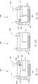
Figure 11 A-11F shows the example having with respect to the lens system of the adjustable camera lens part of fixed part.
Figure 12 shows an example with the camera lens fixed part of adjusting groove.
Figure 13 A-13C shows an example of the communication device of the example that is attached with the lens system in Figure 11 A-11F.
Figure 14 A-14B shows an example of the communication device with the light reinforcing member being positioned on lens system.
Figure 15 A-15B shows an example with the communication device that is positioned at another light reinforcing member on lens system.
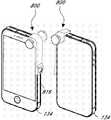
Figure 16 A-16F shows an example of the lens system that comprises joint.
Figure 17 A-17B shows an example of the lens assembly that comprises mounting parts.
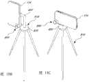
Figure 18 A-18C shows the lens assembly being constituted as in Figure 17 A-17B being arranged on tripod.
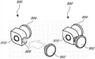
Figure 19 A-19C shows and comprises along a side of lens assembly for storing an example of the storage of camera lens or other devices or the lens assembly of attachment part.
Figure 20 shows and comprises the lens system being used to the attachment parts that use together with annex such as key chain.
Figure 21 shows and comprises the lens system being used to the attachment parts that use together with annex such as necklace.
Figure 22 shows and comprises the lens system being used to the attachment parts that use together with annex such as bracelet.
Figure 23 A-23E shows an example of the lens system that comprises lens case.
Figure 24 A-24D shows an example of the lens system that comprises separable camera lens.
Figure 25 shows an example of the lens system with internal lens.
The communication device that needs other types except illustrating herein and describing also can use.
Embodiment
Hereinafter the concrete example of embodiment of the present disclosure is described in detail.In this instructions, with reference to accompanying drawing, wherein run through instructions and the identical parts of the identical numeral of accompanying drawing.The present invention is not limited in instructions institute's example of specifically illustrating or describing.
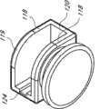
With reference to figure 1A-1I, the example of thelens assembly 110 removably connecting is shown with different schematic diagram.In certain embodiments, as shown in the figure, whatlens assembly 110 was total comprisesfixed part 112 and camera lens part 114.Whatfixed part 112 was total be constituted as is detachably attached to communication device, thereby make near the roughly random camera camera lens in covering communication device or be positioned at it of region thatcamera lens part 114 locates, so thatcamera lens part 114 can be combined optically with random camera, optics strengthening to be provided, to improve, to revise and/or to select.In certain embodiments, as shown in the figure, the shape offixed part 112 can be attached to a region of communication device, and attachment region and attachment means allow user not block or significantly do not see all of communication device or in fact allobservation sections 131 with blocking.
For example,fixed part 112 can comprise thegroove 116 with multiple sidewalls 118.The width ofgroove 116, for example distance betweencorresponding sidewall 118, can be constituted as roughly and the be fixed thickness complementation of the part thatportion 112 is attached of communication device.In certain embodiments, the developed width ofgroove 116 approximates or is slightly less than near the thickness in the communication device shell bight light hole that is positioned at communication device random camera, such as the thickness of upper side corner sections.
In certain embodiments, as shown in the figure, one or more inmultiple walls 118 can havecurve shape 119 along one or more edges, to makefixed part 112 that larger contact distance can be provided along the edge of communication device, reduce the area of crossing device lateral surface that fixedpart 112 stops simultaneously.For example, in certain embodiments, as shown in the figure, along the curve shape at one or more edges ofwall 118 makefixed part 112 along two of communication device roughly intersect or substantially vertical outward flange or lateral surface at least a portion extend and be attached on it, the width of described at least a portion approximates the thickness ofcamera lens part 114, reduces the amount in the space that device front side is blocked simultaneously.In the shown example of Figure 1A-1I, the curve shape at the edge ofwall 118 can remove or omit sharp keen or sharp-pointed bight, bottom, otherwise it can extend in the observation section of communication device and it is caused and is blocked.In certain embodiments, as shown in Figure 2 B, fixed part can not stop discernablely or block observation surface.
The all or part offixed part 112, one or more such as inmultiple walls 118, can be made by soft enough material (for example polymkeric substance or silicones), for example, to allow the distortion (compression of one ormore walls 118, bending or stretching), therebygroove 116 can be widened provisionally,lens assembly 110 is slided on communication device simultaneously, but at least a portion of one ormore walls 118 is enough hard, enough rigidity or have enough elasticity, thereby impel one or more its original positions of getting back inmultiple walls 118, and produce thus the folder power of a part of clamping communication device.Region on the inner side of thewall 118 in the material offixed part 112, particularlygroove 116, also can toughness or have certain sliding resistance, to strengthen the folder power offixed part 112 to communication device.In certain embodiments, folder power and/or sliding resistance can reduce or eliminate permanent or interim installing component is attached to the needs on communication device.For example,lens assembly 110 can repeatedly be attached to communication device and can repeatedly remove from communication device, and without (although not forbidding), independent permanent or semipermanent connection parts are installed on communication device, such as support, magnet, bonding agent or other secure components, simple installation is provided thus, after lens assembly removes, can retains original overall shape, outward appearance, function, the compatibility (for example, with other communication devices or shell) of communication device simultaneously and/or touch.
Fixedpart 112 also can compriseupper wall 120, and its shape is roughly corresponding to the shape at one or more edges of communication device in certain embodiments.As shown in the figure,upper wall 120 has roughly curve shape, with rounded corners 122.Fixedpart 114 also can comprise one or more inside surface camberedsurfaces 124, and it is constituted as one or more exterior parts of avoiding on communication device.For example, as shown in the figure,groove 116 can comprise the surperficial camberedsurface 124 of form of grooves, to avoid the interference of button to communication device or other parts or non-ly have a mind to contact in the time thatlens assembly 110 is attached on communication device.As shown in the figure, thesidewall 118 offixed part 112 can comprise one or more roughly sharp-pointed orangled regions 129.
In certain embodiments, as shown in the figure,fixed part 112 can be constituted as two non-parallel sides of clamping communication device.For example, in use,fixed part 112 can contact at least the first roughly vertically at least the second approximate horizontal of side oredge surface 133 and communication device and roughly transverse side and the top side face of orthogonal side or for example communication device of edge surface 134(of communication device simultaneously).In certain embodiments, by this contact on multiple roughly orthogonal edges or surface, can makefixed part 112 fully precise positioning of repeatable ground in single attachment action, and in attachment process, adjust position or the structure offixed part 112 without user.In certain embodiments, the two or more surface in contacts infixed part 112 can be focused at the upper side corner sections with rounded outer surface.In certain embodiments, as shown in the figure, the communication device that fixedpart 112 is attached to much smaller than it, or the observation section of the communication device being even attached to much smaller than it.In certain embodiments, fixed part can be constituted as and only contact a side or edge (for example roughly vertically or approximate horizontal side or edge), such as the front surface of the side by contacting this edge with rear surface but no longer need to contact another side or edge.The example of this embodiment can roughly form in the following manner: the roughly fixed part of U-shaped, comprises the opening in each side of a upper wall, two sidewalls and sidewall.
In certain embodiments,fixed part 112 can allowlens assembly 110 to be attached to communication device and without nonstandard (non-stock) support on communication device and such as, without the powerful erecting frame (dynamic mounts) onfixed part 112 self (securing member, screw, flexible jig etc.).Therefore, user can for example slide into by the lens assembly 110(that slides simply the bight of communication device) and be attached to the bight of communication device, and can will remove by extracting simply lens assembly, adjust in attachment process without user.In certain embodiments, as shown in the figure,lens assembly 110 can be fixed on communication device by the mode of frictional fit.The attachment of this arrival communication device can avoid the residue of Autoadhesive to deposit, can avoid scratching outer surface or can avoiding other damages or the change to communication device.In certain embodiments, fixed part can be enough wide and/or long, thereby can be suitable for holding the end of communication device and/or lateral side regions (for example two or more bights) and not only hold a bight, other aspects of other embodiment disclosed herein can be used for this embodiment, include but not limited to the formation of the frictional fit between the shape of structure and end and/or the lateral side regions of material and fixed part and communication device.
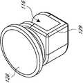
Whatlens assembly 114 was total comprisestransparent lens 128 and the fixedsturcture 126 be conventionally made up of glass or polymkeric substance.Fixedsturcture 126 can be made up of the combination of the material of number of different types or material, for example, such as metal (aluminium or steel) or plastics.Fixedsturcture 126 can comprise: roughly larger area opening, for receivingcamera lens 128; Roughly compared with the region of small size, for being attached to fixed part 112.In certain embodiments,fixed sturcture 126 andfixed part 112 can be constituted as relative to each other and slide or otherwise move in limited mode, adjust (for example, object is the manufacturing tolerance of the position for solving some communication device random camera camera lenses) to allowcamera lens 128 with respect to the position of the random camera camera lens of communication device.As shown in the figure, separable in forfixed part 112 being attached or being fixed to mechanism or the structure of communication device and/or being independent of its operation forcamera lens part 114 being attached or being fixed to the mechanism offixed part 112 or structure.In certain embodiments, as shown in the figure, the outer surface offixed sturcture 126 can be attached region and inwardly be tapered from camera lens receiving area to fixed part, the amount of the material being used to reduce in manufacture process, and size and the weight of minimizing fixed mirror head 114.In certain embodiments, lens assembly can be very little, such as being less than or equal to approximately 21/2 inch, or is laterally less than or equal to approximately 11/2 inch.
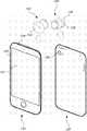
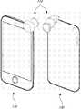
As shown in Fig. 2 A-2B and 3A-3B,lens assembly 110 can be moved to and approach the communication device 130,134 that comprises random camera 132.In certain embodiments,lens assembly 110 can with communication device 130,134 as a system by together with sell or supply.The version of the communication device 130,134 shown in Fig. 2 A-2B and 3A-3B is the iPhone mobile phone that apple (Apple) company sells.Lens assembly 110 can be oriented edge or the bight of thedownward communication device 130 that roughly will be installed tolens assembly 110 and rotate of direction that makesgroove 116 thereon and align, thereby camera lens is roughly alignd with random camera 132.In the time that groove 116 contacts the edge ofcommunication device 130 or bight,groove 116 can be by the outside bending ofwall 118 or bending and slightly expansion.The restoring force that fixedpart 112 produces can impelwall 118 to return to its initial position, and it contributes inuse lens assembly 110 to be fixed on communication device 130.Thencamera lens 128 can be temporarily torandom camera 132 provide amplification, focus on better, clearly or strengthening, change, exercisable or improved image.
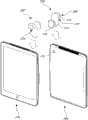
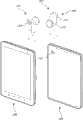
Fig. 4 A-4B and 5A-5B show the example of lens assembly 200,202, and it is constituted as for plate communication device 204,206.In the example shown, the iPad communication device thatcommunication device 204 is sold for Apple,communication device 206 is the Galaxy panel computer that Samsung (Samsung) sells.Lens assembly 200,202 can comprise various parts and structure shown in conjunction with Figure 1A-1I andlens assembly 110 that describe.In certain embodiments, as shown in Fig. 4 A-B and 5A-5B, lens assembly 204,206 can comprise thefixed part 208 with the wall 210,212 that size is different with length.Longer orwider wall 212 can be provided in a side offixed part 208, it is constituted ascamera lens 128 is suspended on tocamera 132 fronts, shorter orless wall 210 can be provided at a side offixed part 208 simultaneously, and it is constituted as on the surface at the observation section place of communication device 204,206 and extends.Fixedpart 208 can be constituted as is attached lens assembly 200,202 securely, reduces or eliminates blocking observation section simultaneously.Hole or otherfunction passage regions 216 can be provided infixed part 208, with in the time that lens assembly 200,202 is attached, allow control or other interactive structures on contact communication device 204,206.
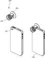
Fig. 6 A-6B shows an example of thelens assembly 302 withfixed part 308, thisfixed part 308 comprisesmultiple attachment arms 304,attachment arm 304 comprises attachment structure, such ashook portion 306, it can be given prominence in a part forcommunication device 306 partially or completely, or its main part with respect toattachment arm 304 is substantially transversely orientated.As shown in the figure, the wider portion at attachment Bei304Ke Cong center starts roughly to narrow down to gradually peripheral narrower part, so that enough structural rigidity and confining forces to be provided.Lens assembly 302 can comprise the various features of other lens assemblies 110,200 described herein.Communication device shown in Fig. 6 A-6B is the EVO communication device that HTC company sells.Attachment arm 304 canattachment lens parts 302 be attached near the device bight thatcamera 310 is not positioned at device, such as EVO device.
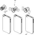
Fig. 7 A-7I shows several schematic diagram of an example oflens assembly 400, and wherein multiple camera lenses 402,404 can be attached to same fixed part 406.In this example, the selection that user can have at least two kinds of different lens types is to be used in special camera application.For example, one in camera lens 402,404 can provide wide-angle view, another the provided flake visual field in camera lens 402,404.Many other camera lens select be also fine.For example, can provide there are different colour filter performances, one or more camera lenses of different attenuation performance, different camera lens coating (such as antireflecting coating) and different other optical characteristics, so that multiple user option to be provided.Different camera lenses can comprise the combination in any of these or other optical property.Fixedpart 406 can comprise the various features of other fixed parts that illustrate and describe herein.
Fig. 8 A-8I and 9A-9E show several schematic diagram withlens assembly 400 in a Fig. 7 A-7I example of similar oridentical lens assembly 400a aspect alot.Lens assembly 400a comprises thatgroove 416 is for receiving a part for communication device.Groove 416 comprises attachment auxiliary surface 418.In the example shown, attachmentauxiliary surface 418 comprises and curving inwardly the surface of (tilt or oblique), its external margin alonggroove 416 or slit opening and locate.In certain embodiments, attachmentauxiliary surface 418 can be positioned on the external margin ofgroove 416 or near it.As shown in the figure, attachment auxiliary surface can be thinner near edge, and along with it extends into the inner and thickening gradually ofgroove 416.
Along withlens assembly 400a is moved in the attachment position of communication device, attachmentauxiliary surface 418 can provide initial contact area or opening 420a(to see Fig. 8 G and 8H near external margin 422), it is enough wide so that appropriate orientation and the attachment of user to device, also provide and be arranged in groove 416 (or further, from the edge oflens assembly 400a) narrower second area 420b, thus, provide more firmly attachment surface bylens assembly 400a being further moved on the attachment region of communication device.In certain embodiments, as shown in the figure, the width ofgroove 416 can be between initial contact area 420a and second area 420b with the change of the mode of level and smooth, gradual change and/or curve.Some embodiment can comprise the shape of many other types.For example, attachmentauxiliary surface 418 can comprise discontinuous surface or series of discrete inclined-plane, projection or groove.Attachmentauxiliary surface 418 can be included in the embodiment of arbitrary lens assembly, and is not limited to be used in thelens assembly 400a shown in Fig. 8 A-8I and 9A-9E.
As shown in Figure 10 A-10C, the front of the somecameras 132 that is positioned atcommunication device 134 in the optional majority of a user camera lens 402,404 is to realize desired shooting effect.In Figure 10 A,lens assembly 400 is moved in the attachment position oncommunication device 134, for example, such as first (minor diameter)camera lens 402 is positioned to the front of randomcamera camera lens 132, will (for example second largest diameter)camera lens 404 be positioned at a relative side of communication device 134.With this orientation, minordiameter camera lens 402 is exercisable, and majordiameter camera lens 404 is not exercisable.In Figure 10 B,lens assembly 400 is removed from communication device, for example, with respect to vertical axes rotation (being approximately 180 ° in this example), and with respect to horizontal rotational shaft so thatgroove 416 roughly for example, is alignd with the attachment surface (shell edge) of communication device.In Figure 10 C,lens assembly 400 is moved oncommunication device 134 again, thereby makes majordiameter camera lens 404 be positioned at the front of randomcamera camera lens 132, minordiameter camera lens 402 is positioned to a relative side of communication device 134.With this orientation, majordiameter camera lens 404 is exercisable, and minordiameter camera lens 402 is not exercisable.In certain embodiments, this structure oflens assembly 400 can allow multiple camera lens to select easily, keeps or store the lens assembly of multiple separation without user.In certain embodiments, inlens assembly 400, can comprise lens type or part more than two kinds, offer thus user's multiple choices.
Figure 11 A-11F shows several schematic diagram of an example oflens assembly 500, and whereincamera lens 502 is attached to fixed part 504.Lens assembly 500 can be attached tocommunication device 134 in the mode that is similar to above-mentioned lens assembly.In the time that user is attached oncommunication device 134 bylens assembly 500, user can with respect to communication device 134(such as directionality ground, along the vertical axes of camera lens, along transverse axis, the combination of these adjustment etc. of lens) adjust (for example tilt, rotate or movement) camera lens 502.User can shiftcamera lens 502 or otherwise move in multiple positions with respect to stationary installation, with reduce and communication device in the random camera of camera lens between misalignment degree, or change the visual angle ofcamera lens 502, or for some other reasons.In certain embodiments, user can shiftcamera lens 502 or otherwise move at least the first and second positions, or at least first, second, and third position, or gradually through adjustment region.In certain embodiments, this adjustment can be in the cavity of formation below 506 of camera lens part 502.The ability that can adjustcamera lens 502 with respect tocommunication device 134 is conducive to solve manufacturing variation or the tolerance of the alignment aspect of position in some communication devices and/or random camera.
In certain embodiments, by camera lens towards thecamera lens 502 that can tilt easily of the pivot (not shown) in the part of communicationdevice.Camera lens 502 is arranged in the groove that thesidewall 508 offixed part 504 forms.In Figure 11 A,camera lens 502 is tilted to the left with respect tocommunication device 134, thereby in the time of attachment, betweencamera lens 502 back sides and the panel offixed part 504,form cavity 506, orform cavity 506 betweencamera lens 502 back sides and communication device, and the outer wall ofcamera lens part 502 be not parallel to the inwall of the camera lens fixedpart 502 adjoining.As shown in the figure, between the internal edge of the back side ofcamera lens 502 andfixed part 504, line orcross section 507, the distance in thefirst side 509 is greater than the distance in the second side 511.With this orientation,camera lens 502 can compensate the bias of the random camera of communication device and aim at.For example, in the direction of adjustment shown in Figure 11 A, the central shaft ofcamera lens part 502 can with the central shaft rough alignment of random camera camera lens 132.Figure 11 B shows thecamera lens 502 in neutral position with respect to communication device.With this orientation,camera lens 502 is without any eccentric aligning of the random camera of compensation communication device 134.Figure 11 C shows thecamera lens 502 being tilted to the right with respect tocommunication device 134, to have formedcavity 506 with mode like Figure 11 category-A.With this orientation,camera lens 502 can compensate deviation or eccentric the aligning or position of the random camera ofcommunication device 134.
In certain embodiments, by the ball-and-socket joint being formed towards theball 510 in the part ofcommunication device 134 and thenest 512 infixed part 504 bycamera lens 502camera lens 502 that can tilt easily.This embodiment can show greatly and is similar to the mode of the embodiment in Figure 11 A-11C and works.Bulb 510 can be close to oblate spheroid roughly, and can have one or more smooth orstraight parts.Bulb 510 can be but not be necessary for spheroidite roughly.In the embodiment shown in Figure 11 D-11E, in the face of the part ofcommunication device 134 is roughly straight orsmooth.Ball 510 can be arranged in thenest 512 with roughly complementary shape, is convenient to the rotation ofcamera lens 502 with respect to fixedpart 502 and communication device 134.In Figure 11 D,camera lens 502 is tilted to the left with respect tocommunication device 134, thereby formscavity 506 betweenball 510 andnest 512 or communication device 134.With this orientation,camera lens 502 can compensate the nonuniformity aspect alignment or position of the random camera of communication device 134.Figure 11 E shows with respect to communication device the roughlycamera lens 502 in neutral position, and wherein at least one wall of fixedpart 504 can be roughly parallel to one of the forward and backward surface ofcamera lens part 502 or both.With this orientation,camera lens 502 withoutcompensation communication device 134 random camera alignment or position aspect any nonuniformity.Figure 11 F shows thecamera lens 502 being tilted to the right with respect tocommunication device 134, to have formedcavity 506 with the similar mode of Figure 11 D.With this orientation,camera lens 502 can compensate the nonuniformity aspect alignment or position of the random camera ofcommunication device 134, or helps to adjust the character of the photographic images generating.In the shown example of Figure 11 D-11F, at least one wall offixed part 504 is one of the non-parallel forward and backward surface in camera lens part 102 or both roughly.As shown in the figure, user can suitably adjustcamera lens part 502 with respect to camera lens fixedpart 504.
As shown in figure 12, camera lens fixedpart 504 can comprise the fixation wall 530 of one or more circular, for receivingcamera lens part 502 in adjustable mode.Fixation wall 530 can comprise a multiple hole 535.The radially inner surface 537 of one or two in hole 535 can comprise the first adjustable structure, and such as adjusting groove 540, its width and the degree of depth are constituted as the second adjustable structure receiving oncamera lens part 502, such as spine or projection.In the example shown, the width of adjusting groove 540 can be much smaller than the width of the inside surface in hole 535 537, thinks thatcamera lens part 502 provides restrained motion relatively in a small amount.For example, in certain embodiments, adjust the width of groove 540 and can be less than or equal to about 1.5mm, and the inside of adjusting groove 540 can dwindle gradually or tilt towards the part of approximate centre or line,camera lens part 502 be removed to needed power from neutral position to increase.The width of the spine oncamera lens part 502 or projection can be less than the width of adjusting groove 540, adjusts approximately 3/4 of groove 540 such as being less than or equal to.First and second adjust structures can closely or securely be assembled together (for example radial interference engagement), simultaneously when user's applied force when the friction force between structure, allows limited movement in contrast to adjustment.In this example, in the time thatcamera lens part 502 is deliberately moved, can adjust to move with respect to camera lens fixedpart 504 by user, butcamera lens part 502 andfixed part 504 can roughly maintain original position until another adjustment.In certain embodiments, the amount of adjusting can be relatively little, is more than or equal to approximately 0.5 ° and/or be less than or equal to approximately 2.5 ° such as the center longitudinal axis ofcamera lens part 502 being oriented to of the orientation of the initial position position after adjusting completely than the center longitudinal axis of camera lens part 102.In certain embodiments,camera lens part 502 can be adjusted to the various positions in (or outside) between these points or scope.The amount of the movement between back of the body surface and the camera lens fixedpart 504 ofcamera lens part 502 also can be relatively little, between the orientation such as initial orientation and after adjusting completely, is more than or equal to about 0.1mm and/or is less than or equal to about 1.0mm.
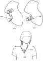
As shown in Figure 13 A-13C, user can adjust with respect tocommunication device 134 inclination ofcamera lens 502, thereby improves aliging or other consistance between the random camera ofcamera lens 502 and communication device 134.In Figure 13 A,camera lens 502 with respect tocommunication device 134 in neutral position.The image of thescreen 560 ofcommunication device 134 departs from center left, with being oriented to left according to (dark angle should be positioned at center with respect to image conventionally) of dark angle (vignetting).Figure 13 B showsuser 590 bycamera lens 502 bias oncommunication device 134 with compensating images that is tilted to the right.Figure 13 C shows the image after correction, makes dark angle placed in the middle with respect to image, even the random camera of communication device is not aimed at suitably.In certain embodiments, the inclination ofcamera lens 502 is adjustable, and when adjustment,user 590 can observe the realtime graphic from random camera from the screen ofcommunication device 134 560, provides about proofreading and correct and adjusts the whether immediate feedback to realize to user.
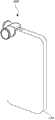
Figure 14 A-14B shows two kinds of schematic diagram of thelens assembly 600 with camera lens part 630 and light enhancing part (such aslight pipe 610).Light pipe 610 can be installed on fixed part 660 or be installed to other parts of lens assembly 600.Light pipe 610 is from light source (such as flashlamp) toeye point 620 transmission lights, thereby it can illuminate the region being taken.In certain embodiments,light pipe 610 is made to the material of the region transmission light that is taken from flashlamp by being convenient to.In certain embodiments, the inside oflight pipe 610 is lined with and is convenient to make to the material of the region transmission light that is taken from random flashlamp.The position offlashlamp 650 shown in Figure 14 A-14B oncommunication device 134 roughly covers or otherwise blocksflashlamp 650 fromrandom camera 132 when makinglens assembly 600 be attached oncommunication device 134 close to enough.In some cases, captured photo when this lightintensity lens assembly 600 that can prevent thatflashlamp 650 from sending is attached.Light pipe 610 is fromflashlamp 650 toeye point 620 transmission lights, and light vertically transmits to illuminate the region in camera front fromeye point 620.
In certain embodiments, some other parts oflight pipe 610, fixed part 660 and/orlens assembly 600 can be constituted as roughly or completely around flashlamp and/or other light outgoing regions to stop or prevent undesirable light transmission or be leaked to from random flashlamp outside the path photoconductive tube 610.This undesirable transmission or reveal and can comprise that light is mapped to the dorsal part of the camera lens part 630 oflens assembly 600 from random flashlamp, or light is mapped to the outside in the region between fixed part 660 and the communication device oflens assembly 600 from random flashlamp.
In certain embodiments, fixed part 660 or another parts can be formed by multiple material, comprise some combinations of polymkeric substance (such as polycarbonate), metal (such as aluminium) etc. or these materials.For example, at least a portion of fixed part 660 can form with multi-step molding process, molded such as multi-point injection, mould embedded component is molded (inserting molding), drape forming molded (overmolding), and/or fixed part 660 can comprise coating, such as bonding agent, pigment or deposit film, with the inside at fixed part 660 and/or outside provide the region different from the hardness of other parts of fixed part 660 or outward appearance.In certain embodiments, together with hard shell or outside can providing with softer inside surface.For example, the interior zone that is intended to be located in the fixed part 660 contacting with the bight of communication device can comprise than the perimeter of fixed part 660 or supporting zone is more soft and/or the surface of viscosity.In certain embodiments, by pressing communication device, softer or more tacky surface can provide stronger light sealing to stop or to prevent that light from revealing.
Figure 15 A-15B shows the two kinds of schematic diagram of thelens assembly 600a with light pipe 610a.In many aspects,light pipe 610a is similar or be equal to above-mentioned light pipe 610.Theeye point 620a oflight pipe 610a can be roughly or completely around camera lens 630a, and general toroidal flash of light is provided.This is to need especially in the application of microspur (close-up shot) photography.Light strengthens part also can be provided by the flashlamp onlens assembly 600 or other light sources, without using or connecting random flashlamp.
In certain embodiments, light strengthen part can comprise can be external flash unit, it is connected tolens assembly 110, be optionally constituted as with communication device (for example, by wireless protocols, such as agreement, or by wired connection, such as USB or connected in series etc.) carry out telecommunication.Flashlamp can be powered and/or be encouraged by communication device.In certain embodiments, flashlamp can rotate, tilt or otherwise move and guide light with the needs according to user with respect to
fixed part 112.

In certain embodiments, as shown and described, lens assembly can comprise the fixed part with attachment structure, this attachment structure can be constituted as and be removably attached to communication device, even when communication device roughly smooth or smooth and while not thering is corresponding attachment mechanism near region random camera.By this way, communication device is without permanent or interim change, reconstruct, damage surface or otherwise change its outward appearance to allow the attachment of lens assembly.In certain embodiments, after lens assembly is removed, this layout can allow communication device accessible and unobstructedly normally use.But, in certain embodiments, be useful or necessary for the change of communication device with attachment lens assembly.
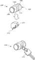
Figure 16 A-16F shows the schematic diagram of lens system 700.Lens system 700 can comprise lens assembly 702.Lens assembly 702 can be similar to other lens assemblies described herein.For example,lens assembly 702 can comprise andlens assembly 400 or the similar or identical structure of400a.Lens assembly 702 can comprise the camera lens 704,706 of one or more attachments (for example coupling releasedly or integrally formation) to same fixed part 708.Utilize more than one camera lens, user can have the selection of at least two kinds of different lens types to be used in special camera application.For example, one in camera lens 704,706 can provide wide-angle view, another the provided flake visual field in camera lens 704,706.Fixedpart 708 can comprise the various features of other fixed parts that illustrate and describe herein.For example,fixed part 708 can comprisegroove 709.
Joint 710 also can comprise the second joint connecting portion 716.The size of the secondjoint connecting portion 716 and/or shape can be formed as it is accommodated in thegroove 709 on lens assembly 702.The secondjoint connecting portion 716 can comprise at least oneopening 718, to allow the optical communication between the corresponding random camera on camera lens 704,706 andcommunication device 720.
Joint 710 can allowlens assembly 702 to use together from one or more different communication devices.For example, joint 710 can allow lens assembly and size, thickness and/or shape be different from lens assembly the different communication device of communication device that conventionally designed for it use together.For example, in certain embodiments,communication device 720 can comprise the iPod Touch device that Apple manufactures, and another kind of communication device can comprise it being the iPhone being produced by Apple equally.IPhone is conventionally thicker more greatly than iPodTouch.If lens assembly 702 is designed to and size is formed as being specially adapted for being arranged on iPhone above instead of being arranged on iPod Touch, user can use joint 710 so thatlens assembly 702 is used together withcommunication device 720 convenient and simplely.
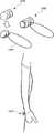
Figure 17 A-17B shows an example ofattachment parts 800, and theseattachment parts 800 are intended to be arranged on the application with pictures taken or video in supporting construction for communication devicetemporarily.Attachment parts 800 can comprise one or more camera lenses 802,804 that are attached to same fixed part 806.Fixed part 806 can comprise similar or be equal to thegroove 808 of above-mentioned groove, for example, forattachment parts 800 being attached to a part (bight) for communication device 134.In certain embodiments, fixedpart 806 also can comprise stable or retaining element, such as at least one or more elongated ridges 810,812.Elongated ridges 810,812 can start to extending at a distance from camera lens 802,804, and can be used toattachment parts 800 to clamp and/or be fixed on the correct position on communication device 134.In certain embodiments, as shown in the figure, the width of elongated ridges 810,812 is less than lens assembly and is constituted as the thickness of the communication device that will be attached, and surface is observed in the front portion that elongated ridges 810,812 extends across communication device along narrow forward edge, and stops before blocking any observable part of viewing area.Fixedpart 806 also can comprise theconnection opening 814 of the one end that is positioned atattachment parts 800.
As shown in Figure 17 B,attachment parts 800 can be attached to such as iPhone of communication device 134(), thus make elongated ridges 810,812 extend across thelateral edges 816 ofcommunication device 134 and be clamped on this lateral edges 816.Ridge 810,812 can contribute toattachment parts 800 to be fixed on the correct position on communication device 134.Except ridge 810,812, also can use the structure of other types.
As shown in Figure 18 A-18C,attachment parts 800 can be attached to such as tripod of supporting construction 818().For example,attachment parts 800 can be attached to thebase portion 820 of supporting construction 818.The fixedpart 806 ofattachment parts 800 can be installed or be attached to by spiral to base portion 820.In certain embodiments, connection opening 814 can comprise internal thread, and base portion can comprise screw or have externally threaded other structures, therebybase portion 820 can be screwed in connection opening 814.The connection of other types is also fine, comprise between thepermission attachment parts 800 of be connected mechanism or other types and supportingconstruction 818 fast, the bindiny mechanism of releasable connection.
In certain embodiments, thebase portion 820 of supportingconstruction 818 can comprise hold-downarm 822, or is connected to hold-down arm 822.In certain embodiments, thefixed part 806 ofattachment parts 800 can comprise hold-down arm 822.Hold-down arm 822 can be used to adjust the position of communication device 134.For example, as shown in Figure 18 C, there is no hold-downarm 822,communication device 134 is positioned at the top of supportingconstruction 818 with approximate horizontal or lateral attitude, but while thering is hold-downarm 822, as shown in Figure 18 B,communication device 134 is positioned at a side ofbase portion 820, and in vertical position.Hold-down arm or the structure of other types are also fine.In certain embodiments, as shown in the figure,attachment parts 800 comprise one or more camera lenses, and in certain embodiments,attachment parts 800 do not have camera lens.
Figure 19 A-19C shows thelens assembly 900 of the storage that allows extra camera lens, lens cap or other devices.Lens assembly can comprise one or more camera lenses 902,904 that are attached to same fixed part 906.Fixed part 906 can comprise the groove (not shown) that is similar to above-mentioned groove, for example, forlens assembly 900 being attached to a part (bight) forcommunication device 134.
In certain embodiments,store attachment part 908 and can allow store and/or carry one or more devices (for example camera lens) along a side oflens assembly 900, until need to use time.In the time of needs operative installations, this device can be removed from storingattachment part 908, and is attached along the zones of different of lens assembly 900.For example, in certain embodiments, and as shown in Figure 19 A,camera lens 902 can be removed from theopening 910 along fixed part 906.Opening 910 can comprise the screw thread or other structures that are generally used for fixed lens 902.Once remove,camera lens 902 can be attached to along a side oflens assembly 900 and store attachment part 908.At this moment, if necessary, different camera lenses can be inserted into opening 910.Once need againcamera lens 902, can removecamera lens 902 from storingattachment part 908, and again be put back inopening 910.
Figure 20-22 show the example of thelens system 1000 using together with the annex of carrying (such as key, necklace, bracelet or other devices).Lens system 1000 can comprise lens assembly 1002.Lens assembly 1002 can be similar or be equal to above-mentioned arbitrary lens assembly.For example,lens assembly 1002 can be similar tolens assembly 400 or 400a.Lens assembly 1002 can comprise one ormore camera lenses part 1008 can comprise the various features of other fixed parts that illustrate and describe herein.For example, fixedpart 1008 can comprisegroove 1010.
Figure 23 A-23E shows and can be used to reduce camera lens and send out reflective and an example of thelens system 1100 oflen.Lens system 1100 can comprise lens assembly 1102.Lens assembly 1102 can comprise similar or be equal to the structure of lens assembly described herein.For example,lens assembly 1102 can be similar to lens assembly 110.Lens assembly 1102 can comprise one ormore camera lenses 1104 that are attached to same fixed part 1106.Fixedpart 1106 can comprise the various features of other fixed parts that illustrate and describe herein.For example, fixedpart 1106 can comprise groove (not shown).
In use,lens case 1108 can be releasably attached tocamera lens 1104, for example, by simply the opening of lens case 1,108 1110 being slided on theedge 1116 of camera lens 1104.Lens case 1108 can be fixed on correct position by frictional fit, although other bindiny mechanisms are also fine.Once attachment,skirt section shield 1108 as required.Like thisskirt section re-use camera lens 1104, can removelens case 1108 fromlens assembly 1102, overturn 180 °, as shown in Figure 23 C-23E, and be put back on camera lens 1104.In this position,lens case 1108 not only can easily be stored in order to later use, can also contribute tolen 1104 and/orlens assembly 1102 to avoid damage and/or wearing and tearing.
As 24A-24D shows an example oflens system 1200, it can comprise alternative connection and the camera lens of dismounting or multiple different alternative connects and the interchangeable lens ofdismounting.Lens system 1200 can comprise lens assembly 1202.Lens assembly 1202 can be similar in lens assembly described herein.For example,lens assembly 1202 can be similar to lens assembly 110.Lens assembly 1202 can comprise one ormore camera lenses 1204 that are attached to same fixed part 1206.Fixedpart 1206 can comprise the various features of other fixed parts that illustrate and describe herein.For example, fixedpart 1206 can comprise groove (not shown).
As mentioned above,lens system 1200 can comprise the function that exchanges camera lens.Therefore,lens assembly 1204 can be removably attached to fixed part 1206.For example, fixedpart 1206 can comprise camera lens attachment portion 1208.Camera lens 1204 can removably be attached to fixedpart 1206 in camera lens attachment portion 1208.For example, cameralens attachment portion 1208 can comprise the threaded opening of tool, and camera lens 1204(or other camera lenses) can be screwed inopening 1208, or camera lens can interlock or be pushed into simply in opening 1208.Other bindiny mechanisms are also fine.For example, camera lens can be provisionally pinned by bayonet mount or magnetic mount or other structures that can use.
Figure 25 shows the example of thelens system 1200 that comprises one or more internal lens parts.In certain embodiments,lens system 1200 can comprise embedded lens assembly 1216.Fixed part 1206 or embeddedmirror head member 1216 can comprise connecting portion, and such as threaded portion, it can be similar to above-mentioned camera lens attachment portion 1208.Threaded portion can be convenient to removably will be attached to fixedpart 1206 such as the camera lens of camera lens 1204.In certain embodiments, fixedpart 1206 and/or embeddedmirror head member 1216 can comprise camera lens 1218.As shown in the figure, embeddedmirror head member 1216 can substantially be imbedded or be inserted in the wall of fixed part 1206.In certain embodiments,camera lens 1218 can be micro-lens, and it is constituted as image is amplified by least 4 times.Many different enlargement factors are also fine.In certain embodiments,camera lens 1218 can be micro lens, and it is constituted as and amplifies at least about 5 times and/or be less than or equal to approximately 15 times etc.In certain embodiments, multiple camera lenses for example can be constituted as, by using the spacing of for example, handling between camera lens such as control lever or revolving actuator (thumb thumb wheel) that variable optical magnification (, amplification characteristic) is provided.
Although the present invention is disclosed with the content of certain preferred embodiment and example, but it will be appreciated by persons skilled in the art that the present invention can exceed the scope of concrete disclosed embodiment and extend to alternative embodiment and/or use of the present invention with and apparent modification and equivalent.Can also be expected that, the specific features of embodiment and aspect form various combinations or sub-combination, this falls within the scope of the invention all the time.Therefore, it should be understood that the various features of disclosed embodiment and aspect can mutually combine or mutually replace to form disclosed various forms of the present invention.
Claims (58)
1. for changing the detachable mirror head unit of image for the light being received by the random camera of device for mobile communication, described detachable mirror head unit comprises:
The fixed part with the first side and the second side, described fixed part is set to be removably attached to device for mobile communication;
The first camera lens, attachment maybe can be attached to described first side of described fixed part; And
The second camera lens, attachment maybe can be attached to described second side of described fixed part;
Described fixed part is set in the time that described camera lens is attached to described fixed part the position before one in described the first camera lens or the second camera lens folding corner region above that is roughly positioned at described device for mobile communication, while being removably affixed to described device for mobile communication with the described fixed part of box lunch, roughly align with the random camera of described device for mobile communication, and described fixed part be set in the time that described camera lens is attached to described fixed part simultaneously by another in described the first camera lens or the second camera lens be roughly positioned at described device for mobile communication below after position,
Wherein said the first camera lens and the second camera lens are not configured to optical communication each other in the time that described fixed part is attached to described device for mobile communication; And
Wherein said the first camera lens and the second camera lens are set to substantially can change in the following manner with respect to the position of device for mobile communication: dismantle described fixed part from described device for mobile communication, around one roughly the longitudinal axis rotate described fixed part, and described fixed part is affixed to described device for mobile communication again.
2. the combination of detachable mirror head unit and device for mobile communication as claimed in claim 1.
3. detachable mirror head unit as claimed in claim 1, wherein said fixed part be set in the time being affixed to described device for mobile communication described in the first camera lens and the second camera lens the two roughly along an axle location, described axle be approximately perpendicular to described device for mobile communication front and back the two.
4. lens assembly as claimed in claim 1, also comprises the groove on bottom side, and it is set to hold the edge of described device for mobile communication.
5. lens assembly as claimed in claim 4, the distance that wherein said groove is set to extend across in the time that described lens assembly is affixed to described device for mobile communication is less than the whole distance across the top of device for mobile communication.
6. lens assembly as claimed in claim 1, the two is set to the same vertical edge near described device for mobile communication in the time that described lens assembly is affixed to described device for mobile communication wherein said the first camera lens and the second camera lens.
7. for changing an attachment lens device for the image being received by the random camera of communication device, this dismountable attachment lens device comprises:
The fixed part with the first side and the second side, described fixed part is set to be removably attached to communication device;
The first camera lens, attachment maybe can be attached to described first side of described fixed part;
The second camera lens, attachment maybe can be attached to described second side of described fixed part;
Described fixed part be set in the time that described camera lens is attached to described fixed part by one in described the first camera lens or the second camera lens be positioned at described communication device above before position, while being removably affixed to described communication device with the described fixed part of box lunch, roughly cover the front random camera of described communication device, and described fixed part be set in the time that described camera lens is attached to described fixed part simultaneously by another in described the first camera lens or the second camera lens be roughly positioned at described communication device below after position;
Wherein be positioned at described communication device above before camera lens communicate by letter with described front random camera light, and be positioned at camera lens and the not optical communication of described front random camera afterwards below of described communication device.
8. attachment lens device as claimed in claim 7, the direction of being wherein arranged to change described device substantially to change the position of described the first camera lens and the second camera lens in the time being affixed to described communication device.
9. attachment lens device as claimed in claim 8, wherein said dismountable lens assembly be also set to pivot roughly to change in the time being attached to described device for mobile communication described in the position of the first camera lens and the second camera lens, wherein said axle is approximately perpendicular to the axle above that extends through one of described camera lens.
10. the combination of an attachment lens device as claimed in claim 7 and communication device.
11. attachment lens devices as claimed in claim 7, wherein said fixed part be set in the time being affixed to described device for mobile communication described in the first camera lens and the second camera lens the two roughly along an axle location, described axle be approximately perpendicular to described device for mobile communication front and back the two.
12. attachment lens devices as claimed in claim 7, also comprise the groove on bottom side, and it is set to hold the edge of described communication device.
13. attachment lens devices as claimed in claim 12, wherein said groove is set to extend the partly top across communication device in the time that described attachment lens device is positioned device for mobile communication.
14. lens assemblies as claimed in claim 7, the two is set to wherein said the first camera lens and the second camera lens in the time that described attachment lens device is positioned described device for mobile communication near the same vertical edge of communication device and away from the relative vertical edge of communication device.
15. 1 kinds of manufactures are used for the method for the attachment lens assembly of communication device, comprising:
The first camera lens is provided;
The second camera lens is provided;
Fixed part is provided, described fixed part is set to hold described the first camera lens and the second camera lens at the corresponding diverse location place of described fixed part, to allow user that the edge of communication device is contacted with fixed part, locating near one in the described camera lens random camera in the folding corner region of the first surface of described communication device, another in described camera lens located near the second surface of described communication device, the second surface of wherein said communication device is roughly relative with the first surface of described communication device simultaneously.
16. methods as claimed in claim 15, wherein said the first camera lens and the not optical communication each other in the time being attached to communication device of the second camera lens.
17. methods as claimed in claim 16, wherein said first surface is that front surface and the described second surface of described communication device is the rear surface of described communication device.
18. methods as claimed in claim 17, wherein said fixed part is set to hold the edge of communication device in the groove of described fixed part, removably to fix described fixed part to described communication device.
19. methods as claimed in claim 18, wherein said the first camera lens and the second camera lens are configured to produce different optical effects.
20. methods as claimed in claim 19, wherein said fixed part is configured to be only affixed on a bight of described communication device.
21. methods as claimed in claim 20, wherein said fixed part is configured to be attached by the frictional fit between described fixed part and the bight of described communication device.
22. 1 kinds are affixed to servicing unit the method for device for mobile communication, comprise the following steps:
Obtain the servicing unit with fixed part, described fixed part has at least antetheca and transmittance section;
Near the random camera of device for mobile communication, fixed part is affixed to device for mobile communication, makes at least two substantially vertical sides at the contact of fixed part described in the folding corner region of described device for mobile communication device for mobile communication;
Wherein, in order to be retained to the attachment of described device for mobile communication, described fixed part does not need to contact the extra side of described device for mobile communication.
23. 1 kinds for changing the optics attachment device of image of the light being received by the random camera of device for mobile communication, and described optics attachment device comprises:
Fixed part, described fixed part is set to be fixed to removably device for mobile communication, described device for mobile communication has the first edge, the second edge, the 3rd edge, the 4th edge, front surface and rear surface, and the first edge of described device for mobile communication and the second edge roughly parallel to each other, the 3rd edge and the 4th edge of described device for mobile communication are roughly parallel to each other, and the rear surface of described device for mobile communication is the surface that comprises user's visual-display screen, and the front surface of described device for mobile communication is the surface that comprises random camera;
Described fixed part comprises at least antetheca, and at least a portion of described fixed part is set to be removably positioned on the front surface of described device for mobile communication near the random camera of device for mobile communication and near the first edge of described device for mobile communication and the bight of the device for mobile communication that the 3rd edge crosses, described fixed part is configured to be firmly held on device for mobile communication, without the second edge or the 4th edge contact of described fixed part and device for mobile communication, and without the powerful erecting frame of screw; And
At least one attachment maybe can be affixed to the parts of described fixed part, it is set to receive at the front surface of described device for mobile communication the surround lighting being mapped on described device for mobile communication front surface, and is set to change described light before described light is received by the random camera of described device for mobile communication.
24. 1 kinds of optics as claimed in claim 23 are attached the combination of device and device for mobile communication.
25. optics attachment devices as claimed in claim 23, wherein said fixed part is set to remain on described device for mobile communication and without powerful erecting frame.
26. optics attachment devices as claimed in claim 23, wherein said fixed part is set to be securely held on device for mobile communication by frictional fit.
27. optics attachment devices as claimed in claim 26, the realization of wherein said frictional fit is without the powerful erecting frame on optics attachment device.
28. 1 kinds of optics attachment devices, it is set to removably be affixed to device for mobile communication, and described optics attachment device comprises:
Fixed part, comprises at least front portion, top and sidepiece, and described front portion is attached maybe can be affixed to optics;
Described fixed part is set to be removably affixed to device for mobile communication, make the top of described fixed part be set to contact described top along the whole length of the top that is less than described device for mobile communication, and the sidepiece of described fixed part is set to contact described side margins along the whole length of the side margins that is less than described device for mobile communication, described fixed part is set to when being prevented from by when attachment sliding on described device for mobile communication and described fixed part can keep securely described fixed part without the powerful erecting frame of screw on described device for mobile communication,
Wherein said optics comprises optical region, and described optical region is set in the time that described fixed part is attached to described device for mobile communication the surround lighting before the random camera of the described device for mobile communication that receives the folding corner region that is arranged in described device for mobile communication and changes described surround lighting.
29. 1 kinds of optics as claimed in claim 28 are attached the combination of device and device for mobile communication.
30. optics attachment devices as claimed in claim 28, the front portion of wherein said fixed part is set to contact the front portion of device for mobile communication.
31. optics as claimed in claim 28 attachment devices, fixed part is set up the top of the described device for mobile communication that will be attached and the external surface shape of side margins described in the external surface shape approximate match of the top of wherein said fixed part and sidepiece.
32. 1 kinds of optics attachment devices, are set to removably be affixed to device for mobile communication, and described optics attachment device comprises:
Fixed part, comprises front portion, rear portion, top and sidepiece, and described anterior attachment maybe can be affixed to optics, and front portion, top, sidepiece and rear portion are formed single one-piece construction;
Described fixed part is set to be removably affixed to device for mobile communication, make the top of described fixed part be set to contact described top along the whole length of the top that is less than described device for mobile communication, and the sidepiece of described fixed part is set to contact described side margins along the whole length of side margins that is less than described device for mobile communication, described fixed part is set to prevent from sliding on described device for mobile communication in the time being attached;
Wherein said optics comprises optical region, and described optical region is set in the time that described fixed part is attached to described device for mobile communication the surround lighting before the random camera of the described device for mobile communication that receives the folding corner region that is arranged in described device for mobile communication and changes described surround lighting.
33. 1 kinds of optics as claimed in claim 32 are attached the combination of device and device for mobile communication.
34. optics attachment devices as claimed in claim 32, the front portion of wherein said fixed part is set to contact the front portion of described device for mobile communication.
35. optics attachment devices as claimed in claim 34, the rear portion of wherein said fixed part is set to contact the rear portion of described device for mobile communication.
36. optics attachment devices as claimed in claim 32, wherein said fixed part can keep securely described fixed part without the powerful erecting frame of screw on described device for mobile communication.
37. optics as claimed in claim 32 attachment devices, fixed part is set up the top of the described device for mobile communication that will be attached and the external surface shape of side margins described in the external surface shape approximate match of the top of wherein said fixed part and sidepiece.
38. 1 kinds are set to removably be affixed to the optics attachment device of device for mobile communication, have the random camera of the top zone line on the first surface that is arranged in described device for mobile communication in described device for mobile communication, and described optics attachment device comprises:
Fixed part, comprises the first arm, and described the first arm is set to contact described device for mobile communication in the zone line of the top along described device for mobile communication; Described fixed part comprises the second arm separating with described the first arm, described the second arm be set to isolated with the bight of described device for mobile communication, along contacting described device for mobile communication in the region of described device for mobile communication one side, described the first arm and the second arm comprise hook portion, it is set to partly give prominence on second of described device for mobile communication, and described second facing to the direction relative with the described first surface of described device for mobile communication; And described fixed part comprises the zone line between described the first arm and the second arm, at least a portion of described zone line is set to the random camera location near described device for mobile communication in the time that described fixed part is attached to described device for mobile communication; And
Optics, in described zone line, attachment maybe can be affixed to described fixed part, makes described optics be set to change the light being received by the random camera of described device for mobile communication.
39. 1 kinds of optics as claimed in claim 38 are attached the combination of device and device for mobile communication.
40. optics attachment devices as claimed in claim 38, wherein said optics is camera lens.
41. optics attachment devices as claimed in claim 40, wherein said camera lens is enlarging lens.
42. optics attachment devices as claimed in claim 40, wherein said camera lens is fish eye lens.
43. optics attachment devices as claimed in claim 40, wherein said camera lens is wide-angle lens.
44. optics attachment devices as claimed in claim 38, wherein said optics reduces dazzle.
45. optics attachment devices as claimed in claim 38, wherein said optics filter light.
46. optics attachment devices as claimed in claim 38, wherein said fixed part is set to anti-skidding in the time being positioned described device for mobile communication.
47. optics as claimed in claim 38 attachment devices, wherein said fixed part is set to be affixed to securely described device for mobile communication and without powerful erecting frame.
48. optics as claimed in claim 38 attachment devices, wherein said fixed part is set to be affixed to securely described device for mobile communication and without the powerful erecting frame of screw.
49. 1 kinds of methods for the manufacture of optics attachment device, described optics attachment device is set to removably be affixed to device for mobile communication, in described device for mobile communication, have the random camera of the central area on the first surface that is arranged in described device for mobile communication, described optics attachment device comprises:
Fixed part is provided, comprises the first arm, described the first arm is set to contact described device for mobile communication in the zone line of the top along described device for mobile communication; Described fixed part comprises the second arm separating with described the first arm, described the second arm be set to isolated with the bight of described device for mobile communication, along contacting described device for mobile communication in the region of described device for mobile communication one side, described the first arm and the second arm comprise hook portion, it is set to partly give prominence on second of described device for mobile communication, and described second facing to the direction relative with the described first surface of described device for mobile communication; And described fixed part comprises the zone line between described the first arm and the second arm, at least a portion of described zone line is set to the random camera location near described device for mobile communication in the time that described fixed part is attached to described device for mobile communication; And
Optics is provided, and in described zone line, attachment maybe can be affixed to described fixed part, makes described optics be set to change the light being received by the random camera of described device for mobile communication.
50. methods as claimed in claim 49, also comprise described device for mobile communication are provided.
51. methods as claimed in claim 49, wherein said optics is camera lens.
52. methods as claimed in claim 51, wherein said camera lens is enlarging lens.
53. methods as claimed in claim 51, wherein said camera lens is fish eye lens.
54. methods as claimed in claim 49, wherein said optics reduces dazzle.
55. methods as claimed in claim 49, wherein said optics filter light.
56. methods as claimed in claim 49, wherein said fixed part is set to anti-skidding in the time being positioned described device for mobile communication.
57. methods as claimed in claim 49, wherein said fixed part is set to be affixed to securely described device for mobile communication and without powerful erecting frame.
58. methods as claimed in claim 49, wherein said fixed part is set to be affixed to securely described device for mobile communication and without the powerful erecting frame of screw.
Applications Claiming Priority (8)
| Application Number | Priority Date | Filing Date | Title |
|---|---|---|---|
| US201161454136P | 2011-03-18 | 2011-03-18 | |
| US61/454136 | 2011-03-18 | ||
| US201161503835P | 2011-07-01 | 2011-07-01 | |
| US61/503835 | 2011-07-01 | ||
| US201261585857P | 2012-01-12 | 2012-01-12 | |
| US61/585857 | 2012-01-12 | ||
| US13/366227 | 2012-02-03 | ||
| US13/366,227US8279544B1 (en) | 2011-03-18 | 2012-02-03 | Selectively attachable and removable lenses for communication devices |
Related Parent Applications (1)
| Application Number | Title | Priority Date | Filing Date |
|---|---|---|---|
| CN201280000210.XADivisionCN102804018B (en) | 2011-03-18 | 2012-03-06 | Optionally attachable and detachable lenses for communication devices |
Publications (1)
| Publication Number | Publication Date |
|---|---|
| CN103869444Atrue CN103869444A (en) | 2014-06-18 |
Family
ID=45930998
Family Applications (2)
| Application Number | Title | Priority Date | Filing Date |
|---|---|---|---|
| CN201410098450.9APendingCN103869444A (en) | 2011-03-18 | 2012-03-06 | Selectively attachable and removable lenses for communication devices |
| CN201280000210.XAExpired - Fee RelatedCN102804018B (en) | 2011-03-18 | 2012-03-06 | Optionally attachable and detachable lenses for communication devices |
Family Applications After (1)
| Application Number | Title | Priority Date | Filing Date |
|---|---|---|---|
| CN201280000210.XAExpired - Fee RelatedCN102804018B (en) | 2011-03-18 | 2012-03-06 | Optionally attachable and detachable lenses for communication devices |
Country Status (8)
| Country | Link |
|---|---|
| US (7) | US8279544B1 (en) |
| EP (2) | EP2500758B1 (en) |
| JP (1) | JP5886881B2 (en) |
| KR (1) | KR101571509B1 (en) |
| CN (2) | CN103869444A (en) |
| BR (1) | BR112013005617B1 (en) |
| MX (1) | MX2013010452A (en) |
| WO (1) | WO2012128936A1 (en) |
Cited By (4)
| Publication number | Priority date | Publication date | Assignee | Title |
|---|---|---|---|---|
| CN104633546A (en)* | 2015-01-20 | 2015-05-20 | 江苏欧密格光电科技股份有限公司 | Light emitting device capable of enhancing light effects and changing light angles |
| CN104853075A (en)* | 2015-05-14 | 2015-08-19 | 谢海春 | Camera and method for processing image data at camera |
| CN106534624A (en)* | 2015-09-15 | 2017-03-22 | Lg电子株式会社 | Mobile terminal |
| CN107615137A (en)* | 2015-05-27 | 2018-01-19 | 捷迈克斯系统公司 | Engraved Gem Viewer for Personal Communication Devices |
Families Citing this family (161)
| Publication number | Priority date | Publication date | Assignee | Title |
|---|---|---|---|---|
| US20100328420A1 (en) | 2009-06-29 | 2010-12-30 | Roman Kendyl A | Optical adapters for mobile devices with a camera |
| US8279544B1 (en) | 2011-03-18 | 2012-10-02 | Premier Systems USA, Inc | Selectively attachable and removable lenses for communication devices |
| CN103096655A (en)* | 2011-10-31 | 2013-05-08 | 深圳富泰宏精密工业有限公司 | Fixed structure of outer-mounted lens and portable electronic device with same |
| WO2013070091A2 (en)* | 2011-11-09 | 2013-05-16 | Mark Ross Hampton | Improvements in and in relation to a lens system for a camera |
| USD678379S1 (en) | 2011-12-30 | 2013-03-19 | Premier Systems Usa, Inc. | Lens component |
| US10457441B2 (en) | 2012-01-05 | 2019-10-29 | Portero Holdings, Llc | Case for a communication device |
| USD707669S1 (en)* | 2012-06-01 | 2014-06-24 | Jayson Guzman | Cellular telephone case incorporating rotating camera lens |
| USD695332S1 (en)* | 2012-05-11 | 2013-12-10 | Premier Systems Usa, Inc. | Lens adapter component |
| US20130329311A1 (en)* | 2012-06-06 | 2013-12-12 | William Charles Frazer | Image Alignment Device for Tandem Optics (IAD-TO) |
| US9473760B2 (en)* | 2012-08-08 | 2016-10-18 | Makerbot Industries, Llc | Displays for three-dimensional printers |
| US20140049937A1 (en)* | 2012-08-16 | 2014-02-20 | Cody Skye Buckner | Skye flash |
| US9624958B2 (en) | 2012-09-11 | 2017-04-18 | Carson Optical, Inc. | Adaptor for connecting an electronic device having a camera to an optical device |
| US9195023B2 (en) | 2012-09-12 | 2015-11-24 | Olloclip, Llc | Removable optical devices for mobile electronic devices |
| WO2014047266A1 (en)* | 2012-09-19 | 2014-03-27 | Venntis Technologies LLC | Device for scattering light |
| US9154677B2 (en)* | 2012-09-20 | 2015-10-06 | Apple Inc. | Camera accessory for angled camera viewing |
| USD697958S1 (en) | 2012-10-30 | 2014-01-21 | Premier Systems Usa, Inc. | Lens component |
| US9641734B2 (en)* | 2012-11-09 | 2017-05-02 | Blackberry Limited | Barrier for a lens |
| USD739452S1 (en) | 2012-11-09 | 2015-09-22 | I.Am.Symbolic, Llc | Mobile device camera accessory |
| US20140132832A1 (en)* | 2012-11-09 | 2014-05-15 | I.Am.Symbolic, Llc | Mobile device camera enclosure |
| CN103916495B (en)* | 2012-11-10 | 2017-10-27 | 罗天成 | A new type of smart terminal and a housing connected with the smart terminal |
| US9019420B2 (en)* | 2012-12-19 | 2015-04-28 | Covr Llc | Image redirection system for mobile devices |
| CN103019010A (en)* | 2012-12-21 | 2013-04-03 | 吴刚 | Rotary lens and rotary lens component for mobile equipment cameras |
| WO2014094305A1 (en)* | 2012-12-21 | 2014-06-26 | Intel Corporation | Auxiliary camera lens attachment and light pipe for electric device |
| EP2941670A4 (en)* | 2013-01-07 | 2016-09-21 | Tamaggo Holding Sa | Panoramic camera |
| US9294659B1 (en)* | 2013-01-25 | 2016-03-22 | The Quadrillion Group, LLC | Device and assembly for coupling an external optical component to a portable electronic device |
| USD708652S1 (en)* | 2013-02-13 | 2014-07-08 | Carson Optical, Inc. | Lens magnet adaptor |
| USD708653S1 (en)* | 2013-02-13 | 2014-07-08 | Carson Optical, Inc. | Optical adaptor |
| US9423671B2 (en) | 2013-02-14 | 2016-08-23 | Olloclip, Llc | Accessories for communication devices |
| US9386194B2 (en)* | 2013-02-25 | 2016-07-05 | iOgrapher, LLC | Receptacle for an image capture computing device |
| US10617305B2 (en)* | 2013-02-28 | 2020-04-14 | Canfield Scientific, Incorporated | Dermatoscope devices |
| EP2965153B1 (en)* | 2013-03-06 | 2020-08-05 | Nokia Technologies Oy | Sliding accessory lens mount with automatic mode adjustment |
| US9294660B2 (en) | 2013-03-13 | 2016-03-22 | Olloclip, Llc | Removable lenses for mobile electronic devices |
| WO2014174376A2 (en)* | 2013-04-09 | 2014-10-30 | Oliveira Rui Pedro | Attachable smartphone camera |
| US20140327815A1 (en)* | 2013-05-06 | 2014-11-06 | Cvs Pharmacy, Inc. | Smartphone scanner adapter |
| US10345680B2 (en) | 2013-05-21 | 2019-07-09 | Forward Science Technologies, LLC | Optical filtering attachment |
| JP6245843B2 (en)* | 2013-05-21 | 2017-12-13 | オリンパス株式会社 | Camera operation terminal, imaging system, imaging method, and program |
| US9357109B2 (en)* | 2013-06-13 | 2016-05-31 | Carson Optical, Inc. | Magnetic optical adapter for electronic devices |
| CN103345102A (en)* | 2013-07-08 | 2013-10-09 | 谢虹 | Mobile phone lens amplifier |
| CN103345033A (en)* | 2013-07-08 | 2013-10-09 | 谢虹 | Mobile phone lens amplifier |
| CN103345103A (en)* | 2013-07-08 | 2013-10-09 | 谢虹 | Mobile phone lens amplifier |
| CN103345105A (en)* | 2013-07-08 | 2013-10-09 | 谢虹 | Mobile phone lens amplifier |
| CN103345104B (en)* | 2013-07-08 | 2015-11-25 | 谢虹 | Mobile phone lens amplifier |
| US9661200B2 (en)* | 2013-08-07 | 2017-05-23 | Olloclip, Llc | Auxiliary optical components for mobile devices |
| JP2015057626A (en)* | 2013-08-16 | 2015-03-26 | 國昭 永山 | Lens unit and transmitted-light compound microscope device |
| WO2015030326A1 (en)* | 2013-08-28 | 2015-03-05 | Kim Sung Moo | Lens assembly for mobile terminal |
| KR101485509B1 (en) | 2013-08-28 | 2015-01-26 | 김성무 | Microscope for mobile terminal |
| KR101563400B1 (en)* | 2013-08-28 | 2015-10-26 | 김성무 | Close-up unit for mobile terminal |
| WO2015048143A1 (en)* | 2013-09-26 | 2015-04-02 | Olloclip, Llc | Selectively attachable and removable optical systems for mobile devices |
| US20150003821A1 (en)* | 2013-11-19 | 2015-01-01 | Jeffrey Overall | Camera filter mount and related methods |
| USD727868S1 (en) | 2013-11-21 | 2015-04-28 | Olloclip, Llc | Optical component |
| USD727385S1 (en) | 2013-11-21 | 2015-04-21 | Olloclip, Llc | Optical component |
| USD726796S1 (en) | 2013-11-21 | 2015-04-14 | Olloclip, Llc | Optical component |
| KR200477172Y1 (en)* | 2013-11-21 | 2015-06-16 | 차삼수 | support material for lens installation equipment of mobile device camera |
| JP5872529B2 (en)* | 2013-12-24 | 2016-03-01 | 梅州市▲ショウ▼瑩實業有限公司 | Wristwatch structure with interchangeable built-in lens |
| US10175463B1 (en)* | 2014-01-17 | 2019-01-08 | Torrey Pines Logic, Inc. | Multiple afocal adaptor for mobile devices |
| US9571151B2 (en)* | 2014-02-06 | 2017-02-14 | Olloclip, Llc | Cases for mobile electronic devices configured to receive auxiliary optical devices |
| USD754228S1 (en)* | 2014-02-19 | 2016-04-19 | olioclip, LLC | Optical component |
| US9621690B2 (en) | 2014-03-04 | 2017-04-11 | Houdinix Llc | Cellphone with contoured surfaces |
| US9917935B2 (en) | 2014-03-04 | 2018-03-13 | Houdinix Llc | Multi-layer handheld electronic device |
| USD763250S1 (en) | 2014-04-04 | 2016-08-09 | Houdinix Llc | Electronic device |
| US9569683B2 (en) | 2014-04-07 | 2017-02-14 | Connor W. Brereton | Removable diffraction assembly for electronic device |
| USD792497S1 (en) | 2014-04-09 | 2017-07-18 | Rui Pedro Oliveira | Attachable smartphone camera |
| USD761896S1 (en)* | 2014-04-11 | 2016-07-19 | Olloclip, Llc | Optical component |
| US10088738B2 (en) | 2014-04-11 | 2018-10-02 | Portero Holdings, Llc | Auxiliary optical devices |
| WO2015179876A1 (en)* | 2014-05-23 | 2015-11-26 | Pathonomic | Digital microscope system for a mobile device |
| US9454066B2 (en)* | 2014-06-19 | 2016-09-27 | Olloclip, Llc | Auxiliary optical components for mobile devices |
| WO2016007662A1 (en)* | 2014-07-08 | 2016-01-14 | Padloc Inc. | Imaging and peripheral enhancements for mobile devices |
| USD754116S1 (en) | 2014-08-05 | 2016-04-19 | Olloclip, Llc | Mobile device accessory insert |
| WO2016053476A1 (en)* | 2014-08-07 | 2016-04-07 | Houdinix Llc | Low-profile lens mount |
| US9568808B2 (en) | 2014-08-07 | 2017-02-14 | Houdinix Llc | Low-profile lens mount |
| CN104158932A (en)* | 2014-08-08 | 2014-11-19 | 深圳海偲科技有限公司 | Lens fixing device |
| US9451137B2 (en) | 2014-08-21 | 2016-09-20 | Omnivision Technologies, Inc. | PCB-mountable lens adapter for a PCB-mountable camera module |
| US9304299B2 (en) | 2014-08-21 | 2016-04-05 | Omnivision Technologies, Inc. | Four-piece all-aspheric adapter fisheye lens |
| US9274322B1 (en) | 2014-08-21 | 2016-03-01 | Omnivision Technologies, Inc. | Three-piece all-aspheric adapter fisheye lens |
| USD763340S1 (en)* | 2014-10-02 | 2016-08-09 | Olloclip, Llc | Optical component |
| CN104363340B (en)* | 2014-11-06 | 2017-06-20 | 广东欧珀移动通信有限公司 | Mobile terminal device |
| US9917994B2 (en)* | 2014-11-13 | 2018-03-13 | Medtronic Vascular, Inc. | Visual and tactile assessment tool |
| JP6528396B2 (en) | 2014-12-10 | 2019-06-12 | 富士ゼロックス株式会社 | Imaging unit and imaging system |
| JP2016110029A (en)* | 2014-12-10 | 2016-06-20 | 富士ゼロックス株式会社 | Imaging unit and imaging system |
| US9467608B2 (en) | 2015-01-27 | 2016-10-11 | Moment Inc | Auxiliary lens for mobile photography |
| NZ773836A (en) | 2015-03-16 | 2022-07-01 | Magic Leap Inc | Methods and systems for diagnosing and treating health ailments |
| US9619137B2 (en)* | 2015-03-26 | 2017-04-11 | Motorola Mobility Llc | Portable device touchscreen optimization |
| CA168155S (en)* | 2015-03-31 | 2016-05-17 | Procter & Gamble | Holder for a smart device |
| US9990526B2 (en) | 2015-04-08 | 2018-06-05 | Cognex Corporation | System for capturing a coded image |
| US9990523B2 (en) | 2015-04-08 | 2018-06-05 | Cognex Corporation | Optical accessory for attachment to mobile device |
| US9811702B2 (en) | 2015-04-08 | 2017-11-07 | Cognex Corporation | Optical accessory for attachment to mobile device |
| US9747482B2 (en) | 2015-04-08 | 2017-08-29 | Cognex Corporation | Aimer accessory for capturing a coded image |
| EP3079097B1 (en)* | 2015-04-08 | 2018-08-22 | Cognex Corporation | Optical accessory for attachment to mobile device |
| US10708397B2 (en) | 2015-04-08 | 2020-07-07 | Cognex Corporation | Optical accessory for attachment to mobile device |
| US10075572B2 (en) | 2015-04-08 | 2018-09-11 | Cognex Corporation | Optical accessory for attachment to mobile device |
| US10773108B2 (en)* | 2015-04-20 | 2020-09-15 | Msa Technology, Llc | Self-contained breathing apparatus with thermal imaging capabilities |
| KR101672889B1 (en)* | 2015-04-27 | 2016-11-04 | (주)시원광기술 | Accessory for close-up shot using mobile phone camera |
| KR101683667B1 (en)* | 2015-04-29 | 2016-12-08 | 주식회사 하이소닉 | Lighting accessory for portable device and lighting system thereof |
| WO2016196825A1 (en)* | 2015-06-02 | 2016-12-08 | 360fly, Inc. | Mobile device-mountable panoramic camera system method of displaying images captured therefrom |
| WO2016194194A1 (en) | 2015-06-04 | 2016-12-08 | オリンパス株式会社 | Image pickup system |
| US9936111B1 (en)* | 2015-06-10 | 2018-04-03 | Google Llc | Articulating imaging module for electronic devices |
| CN104967764A (en)* | 2015-06-16 | 2015-10-07 | 成都西可科技有限公司 | Deviation preventing structure for camera of sport camera |
| KR101696683B1 (en)* | 2015-06-18 | 2017-02-01 | 에이치엔티 일렉트로닉스(주) | The portable terminal of recordable pictures |
| DE102015214047B3 (en)* | 2015-07-24 | 2016-04-28 | Tesa Scribos Gmbh | Smartphone lens attachment |
| CN105049569A (en)* | 2015-08-20 | 2015-11-11 | 擎亚国际贸易(上海)有限公司 | Panoramic photo composition method based on front and back cameras of cellphone |
| JP2017044798A (en)* | 2015-08-25 | 2017-03-02 | 齊發光電股フン有限公司 | Short-distance photographing system and its short-distance photographing module |
| US9933816B2 (en) | 2015-08-28 | 2018-04-03 | Vals Tech, Inc. | Waterproof housing with swing arm actuator for use with digital devices and method |
| US9823434B2 (en)* | 2015-08-28 | 2017-11-21 | Vals Tech, Inc. | Lens mount system for waterproof camera housing |
| US10812755B2 (en)* | 2015-10-14 | 2020-10-20 | Utility Associates, Inc. | Article of clothing with video recording device support |
| TWI558202B (en)* | 2015-10-14 | 2016-11-11 | 緯創資通股份有限公司 | Imaging device, imaging system and control method thereof |
| US10230919B2 (en)* | 2015-10-14 | 2019-03-12 | Utility Associates, Inc. | Article of clothing with video recording device support |
| EP4049772A1 (en)* | 2015-10-30 | 2022-08-31 | Seurat Technologies, Inc. | Chamber systems for additive manufacturing |
| US10148799B2 (en) | 2015-11-12 | 2018-12-04 | Portero Holdings, Llc | Auxiliary optical system for use with mobile electronic device in protective case |
| ITUB20159515A1 (en)* | 2015-12-22 | 2017-06-22 | Aiino Srl | ? LAPTOP COMPUTER ACCESSORY? |
| USD828863S1 (en)* | 2015-12-29 | 2018-09-18 | Shenzhen Arashi Vision Co., Ltd. | Camera |
| WO2017117772A1 (en)* | 2016-01-07 | 2017-07-13 | 深圳市琇莹印刷有限公司 | Portable selfie stick |
| CN105527784B (en)* | 2016-02-05 | 2019-01-18 | 博学乐教(北京)教育科技有限公司 | imaging auxiliary device |
| CN107045190A (en)* | 2016-02-05 | 2017-08-15 | 亿观生物科技股份有限公司 | Sample bearing module and portable microscope device |
| CN108885134A (en) | 2016-02-08 | 2018-11-23 | 平等化妆品公司 | Apparatus and methods for formulating and dispensing visually customized cosmetics |
| JP6923552B2 (en) | 2016-04-08 | 2021-08-18 | マジック リープ, インコーポレイテッドMagic Leap,Inc. | Augmented reality systems and methods with varifocal lens elements |
| USD807939S1 (en) | 2016-05-23 | 2018-01-16 | Evoko Unlimited AB | Accessory for a camera lens |
| US10122918B2 (en)* | 2016-06-16 | 2018-11-06 | Maurizio Sole Festa | System for producing 360 degree media |
| US10291866B2 (en) | 2016-06-24 | 2019-05-14 | Moondog Optics, Inc. | Lens attachment for multi-camera device |
| US10031312B2 (en) | 2016-08-10 | 2018-07-24 | Apple Inc. | Adapting camera systems to accessory lenses |
| WO2018030969A1 (en) | 2016-08-12 | 2018-02-15 | Karacor Adem Can | Lens and lighting device attachable to communication devices for use in dental imaging applications |
| US10670826B2 (en)* | 2016-08-12 | 2020-06-02 | Portero Holdings, Llc | Auxiliary optical systems for mobile devices |
| US10015378B2 (en)* | 2016-09-15 | 2018-07-03 | Microsoft Technology Licensing, Llc | Kinematic mount for split camera |
| US10795240B2 (en) | 2016-11-18 | 2020-10-06 | Moment Inc | Protective case for a mobile device |
| US11231577B2 (en) | 2016-11-22 | 2022-01-25 | Alexander Ellis | Scope viewing apparatus |
| US10110719B2 (en)* | 2016-12-12 | 2018-10-23 | Brian Joseph Aberle | Magnification and lighting attachment for mobile telephones |
| IL311431A (en) | 2017-02-23 | 2024-05-01 | Magic Leap Inc | Display system with variable power reflector |
| USD886088S1 (en) | 2017-06-30 | 2020-06-02 | Red.Com, Llc. | Electronic device |
| USD858609S1 (en)* | 2017-07-14 | 2019-09-03 | Motorola Mobility Llc | Camera module |
| WO2019015625A1 (en)* | 2017-07-19 | 2019-01-24 | Lo Tim Fu | Apparatus for assisting mobile terminal in capturing multi-directional image and application method thereof |
| US10162164B2 (en)* | 2017-09-05 | 2018-12-25 | Jeff Overall | Flexion arm mount |
| WO2019073291A1 (en)* | 2017-10-11 | 2019-04-18 | Eyecare Spa | System and device for preliminary diagnosis of ocular disease |
| USD849815S1 (en)* | 2018-01-30 | 2019-05-28 | Becton, Dickinson And Company | Optical component connection module |
| US10750067B2 (en)* | 2018-02-12 | 2020-08-18 | Christopher Jordan Kraemer | Optical filter assembly for image-capturing device |
| KR102013951B1 (en)* | 2018-03-06 | 2019-08-23 | 주식회사 티엠에스글로벌 | Mobile terminal with ultraviolet irradiation lamp |
| US11082596B2 (en)* | 2018-03-25 | 2021-08-03 | Moment Inc | Anamorphic optical assembly for mobile camera-enabled device and device case |
| USD873785S1 (en) | 2018-05-18 | 2020-01-28 | Red Hydrogen Llc | Electronic device |
| USD856393S1 (en)* | 2018-05-21 | 2019-08-13 | Portero Holdings, Llc | Accessory support clip for a mobile electronic device |
| USD849099S1 (en)* | 2018-05-21 | 2019-05-21 | Portero Holdings, Llc | Accessory support clip for a mobile electronic device |
| US20190391464A1 (en)* | 2018-06-21 | 2019-12-26 | Adam Mancuso | Shutter device for a mobile device |
| US10575623B2 (en) | 2018-06-29 | 2020-03-03 | Sephora USA, Inc. | Color capture system and device |
| CN108919593A (en)* | 2018-07-04 | 2018-11-30 | 合肥迪鑫信息科技有限公司 | Intelligent multifunctional feature mobile telephone external camera lens |
| US10948715B2 (en) | 2018-08-31 | 2021-03-16 | Hellman Optics, LLC | Chromatic lens and methods and systems using same |
| US10753729B2 (en)* | 2018-10-02 | 2020-08-25 | Saudi Arabian Oil Company | Photonic sensing analytical device |
| USD844689S1 (en)* | 2018-10-25 | 2019-04-02 | Jeffrey Overall | Gimbal lock |
| US10715706B2 (en)* | 2018-11-23 | 2020-07-14 | Nanning Fugui Precision Industrial Co., Ltd. | Camera module and electronic equipment using the camera module |
| CN111294489A (en)* | 2018-12-26 | 2020-06-16 | 罗天成 | Lens cap, intelligent terminal, digital camera, selfie stick, support and device |
| USD945977S1 (en)* | 2019-01-08 | 2022-03-15 | Apple Inc. | Electronic device |
| JP7333823B2 (en)* | 2019-02-19 | 2023-08-25 | フィットスキン インコーポレイテッド | Systems and methods for using and aligning mobile device accessories for mobile devices |
| US20200367803A1 (en)* | 2019-04-24 | 2020-11-26 | Alexander M. WITKOWSKI | Dermatoscope attachment for mobile devices |
| TWI708988B (en) | 2019-05-21 | 2020-11-01 | 吳政鋒 | Multi-lens transposition device |
| USD1016888S1 (en)* | 2019-05-21 | 2024-03-05 | Guangdong Sirui Optical Co., Ltd. | External lens for mobile terminal |
| CN110266929B (en)* | 2019-07-01 | 2024-07-02 | 广东思锐光学股份有限公司 | Lens structure and additional lens mechanism |
| CN110567958A (en)* | 2019-09-05 | 2019-12-13 | 中国民用航空总局第二研究所 | A smart phone-based fog droplet image acquisition device and method |
| CN111064832A (en)* | 2019-12-30 | 2020-04-24 | 维沃移动通信有限公司 | Electronic equipment |
| USD950633S1 (en)* | 2020-03-10 | 2022-05-03 | Premier Accessory Group LLC | Mounting head |
| US11422391B1 (en)* | 2020-03-31 | 2022-08-23 | Bevan Brathwaite | Colored strobe for mobile phone |
| US11579449B2 (en)* | 2020-05-29 | 2023-02-14 | Microsoft Technology Licensing, Llc | Systems and methods for providing mixed-reality experiences under low light conditions |
| US12162074B2 (en) | 2020-11-25 | 2024-12-10 | Lawrence Livermore National Security, Llc | System and method for large-area pulsed laser melting of metallic powder in a laser powder bed fusion application |
| USD1087930S1 (en)* | 2021-08-10 | 2025-08-12 | Errol A Walters | Smart-phone with an integrated night-vision camera |
| DE102023101416A1 (en)* | 2023-01-20 | 2024-07-25 | Arnold & Richter Cine Technik Gmbh & Co. Betriebs Kg | Use of additional optics, lens system and camera system |
| US12143703B2 (en)* | 2023-03-22 | 2024-11-12 | Apple Inc. | Camera modules with interlocked frames |
Citations (4)
| Publication number | Priority date | Publication date | Assignee | Title |
|---|---|---|---|---|
| CN1694468A (en)* | 2004-05-03 | 2005-11-09 | 三星电子株式会社 | handheld mobile terminal |
| US20070196090A1 (en)* | 2006-02-20 | 2007-08-23 | Sony Corporation | Adapter lens |
| US20070280677A1 (en)* | 2006-05-30 | 2007-12-06 | Marc Thomas Drake | Auxiliary lens attachment for cellular telephones |
| US20090109558A1 (en)* | 2007-10-25 | 2009-04-30 | Glenn F. Schaefer, L.L.C. | Lens And Display Accessory For Portable Imaging Device |
Family Cites Families (133)
| Publication number | Priority date | Publication date | Assignee | Title |
|---|---|---|---|---|
| US971798A (en) | 1910-01-20 | 1910-10-04 | Truls A Somdal | Optical instrument. |
| US2428719A (en) | 1944-09-16 | 1947-10-07 | Curtis Helene Ind Inc | Adjustable lens mount |
| US3090282A (en) | 1959-01-28 | 1963-05-21 | Angenieux Pierre | Mechanism for controlling the axial displacements of optical elements |
| US3133140A (en) | 1960-09-23 | 1964-05-12 | Winchell Paul | Lens cover |
| US3138060A (en) | 1961-10-12 | 1964-06-23 | Voigtlaender Ag | Clamping means for variable focal length projector objective lens |
| US3454323A (en) | 1968-07-15 | 1969-07-08 | Eastman Kodak Co | Adapter for optical elements |
| US3620149A (en) | 1969-08-04 | 1971-11-16 | Olygin Optical Corp | Threaded type coupling device for coupling a lens barrel with a camera body |
| US3680461A (en) | 1971-03-01 | 1972-08-01 | Teledyne Inc | Step-and-repeat camera having an improved film indexing means |
| US3796489A (en) | 1971-05-28 | 1974-03-12 | Canon Kk | Microfiche camera |
| US3828991A (en) | 1973-02-09 | 1974-08-13 | Donald Moore Mac | Carrier for interchangeable camera lenses |
| US3817601A (en) | 1973-05-02 | 1974-06-18 | Eastman Kodak Co | Zoom lens mount |
| US3961349A (en) | 1974-12-16 | 1976-06-01 | Polaroid Corporation | Accessory mounting adaptor for photographic apparatus |
| USD248160S (en) | 1976-06-07 | 1978-06-13 | Designs For Vision, Inc. | Photo adapter microscope accessory |
| USD264046S (en) | 1979-03-30 | 1982-04-27 | Opto-System Ab | Coupling |
| JPS55136037A (en) | 1979-04-12 | 1980-10-23 | Olympus Optical Co | Device for connecting accessory for endoscope |
| US4264167A (en) | 1980-02-04 | 1981-04-28 | Polaroid Corporation | Adapter for coupling a camera with a viewing device |
| USD274336S (en) | 1981-04-15 | 1984-06-19 | Bausch & Lomb Incorporated | Housing for a riflescope eyepiece and reticle |
| USD275766S (en) | 1982-07-12 | 1984-10-02 | Ace Optical Co., Ltd. | Conversion lens for a miniature camera |
| USD274691S (en) | 1982-12-06 | 1984-07-17 | Wallace Robert S | Snap-lock holder |
| USD295871S (en) | 1985-01-03 | 1988-05-24 | Charles Jeffrey R | Image switching attachment for a telescope or similar optical instrument |
| US4760510A (en) | 1987-05-18 | 1988-07-26 | Lahti Uolevi L | Simple mounting for electrical fixture |
| US4893143A (en) | 1988-09-16 | 1990-01-09 | Sheng Huei Wey | Lens base and its accessories for any compact automatic camera |
| US4864333A (en) | 1988-10-11 | 1989-09-05 | Barber Glen M | Camera and facade |
| JPH0622806Y2 (en) | 1989-09-27 | 1994-06-15 | パイオニア株式会社 | Lens frame |
| JPH0358609U (en) | 1989-10-12 | 1991-06-07 | ||
| US5311358A (en) | 1992-10-08 | 1994-05-10 | Time Surgical, Inc. | Universal microscope drape |
| US5461444A (en) | 1993-04-21 | 1995-10-24 | Asahi Kogaku Kogyo Kabushiki Kaisha | Lens holding structure |
| US5416544A (en) | 1993-12-07 | 1995-05-16 | Stapleton; Michael E. | Camera lens attachment to aid focusing |
| US5455711A (en) | 1994-03-08 | 1995-10-03 | Itt Corporation | Magnification lens coupling device for a night vision assembly |
| USD374878S (en) | 1994-03-08 | 1996-10-22 | Itt Corporation | Modular adaptor ring assembly for a night vision device |
| US5781351A (en) | 1995-06-02 | 1998-07-14 | Matsushita Electric Industrial Co., Ltd. | Mounting structure of objective lens for optical pick-up used for optical disk device |
| USD381347S (en) | 1995-09-14 | 1997-07-22 | Canon Kabushiki Kaisha | Wide converter for camera |
| JPH10115858A (en)* | 1996-10-11 | 1998-05-06 | Ricoh Co Ltd | Camera with converter lens switching device |
| USD389500S (en) | 1996-11-15 | 1998-01-20 | Irez Research, Corporation | Video camera |
| USD387787S (en) | 1996-12-23 | 1997-12-16 | Itt Industries, Inc. | Coupling adaptor ring for a night vision device |
| USD398018S (en) | 1997-02-25 | 1998-09-08 | Daewoo Telecom, Ltd. | Camera for use with a computer |
| USD394868S (en) | 1997-02-25 | 1998-06-02 | Daewoo Telecom Ltd. | Camera for use with a computer |
| US5831778A (en) | 1997-06-18 | 1998-11-03 | Behavior Tech Computer Corp. | Device for lenses of various lengths |
| JPH11119335A (en)* | 1997-10-09 | 1999-04-30 | Fuji Photo Film Co Ltd | Close-up adapter |
| US5950017A (en) | 1997-10-21 | 1999-09-07 | Reff; Albert A. | Camera system including a camera mounting apparatus for obtaining close-up photographs |
| JP3736085B2 (en) | 1997-11-26 | 2006-01-18 | コニカミノルタフォトイメージング株式会社 | Zoom lens barrel |
| JP2000311427A (en) | 1999-04-27 | 2000-11-07 | Hitachi Ltd | Disk discriminating method and apparatus |
| US6441971B2 (en) | 1999-09-27 | 2002-08-27 | Alex Ning | Compact lens with external aperture stop |
| BR0108844A (en)* | 2000-02-29 | 2002-12-03 | Kyocera Corp | Portable information terminal and digital camera for portable information terminal and digital camera system / portable information terminal |
| JP3822419B2 (en)* | 2000-07-06 | 2006-09-20 | 三菱電機株式会社 | Imaging device, imaging device-integrated handset telephone, and imaging device-integrated portable information device |
| US7800043B2 (en) | 2000-09-15 | 2010-09-21 | Night Vision Corporation | Night vision goggles with detachable or reattachable modular components |
| JP2002281142A (en) | 2001-03-19 | 2002-09-27 | Matsushita Electric Ind Co Ltd | Mobile terminal device with camera function |
| JP2002318335A (en) | 2001-04-20 | 2002-10-31 | Fuji Photo Optical Co Ltd | Lens holding frame |
| US6752516B1 (en) | 2001-10-30 | 2004-06-22 | Joshua Z. Beadle | Light fixture mounting |
| JP2003295307A (en)* | 2002-03-29 | 2003-10-15 | Fuji Photo Film Co Ltd | Camera system |
| JP2004191897A (en) | 2002-12-09 | 2004-07-08 | Yoshiaki Kimura | Lens adapter |
| JP3951299B2 (en) | 2003-02-20 | 2007-08-01 | ソニー株式会社 | Lens adapter |
| US7619686B2 (en) | 2003-03-24 | 2009-11-17 | Kantan Inc. | Apparatus for a combination camcorder-handset device |
| US7035023B2 (en) | 2003-04-24 | 2006-04-25 | Canon Kabushiki Kaisha | Lens system |
| US7324156B2 (en) | 2003-05-02 | 2008-01-29 | Motorola Inc. | Attachable carrier having an optical accessory for a portable electronic device |
| JP3098262U (en) | 2003-06-02 | 2004-02-26 | 有限会社トダ精光 | Accessory lens |
| US7040750B2 (en)* | 2003-10-24 | 2006-05-09 | E'lite Optik U.S. L.P. | Rotatable and removable auxiliary eyewear system with snap alignment |
| US20050099526A1 (en) | 2003-11-11 | 2005-05-12 | Cheng-Hsing Wu | Device for attaching lens to digital camera |
| US6924950B2 (en)* | 2003-11-12 | 2005-08-02 | Nokia Corporation | Apparatus for viewing a display of a portable communication device |
| US6967790B2 (en) | 2004-04-27 | 2005-11-22 | E-Benk Tech Co., Ltd. | Detachable zoom lens assembly |
| DE502004010408D1 (en) | 2004-07-02 | 2009-12-31 | Schoelly Fiberoptic Gmbh | DEVICE AND USE OF THE APPARATUS FOR RECORDING AND PROCESSING AN IMAGE |
| US7144262B2 (en) | 2004-07-14 | 2006-12-05 | Mobitek Communication Corp. | Versatile connector for mobile telephone |
| KR101074284B1 (en)* | 2004-09-23 | 2011-10-17 | 에이저 시스템즈 인크 | Mobile communication device having panoramic imagemaking capability |
| NZ555090A (en) | 2004-11-11 | 2010-10-29 | Daltray Pty Ltd | Sigmoidoscope with optical coupling element |
| US20060142053A1 (en) | 2004-12-15 | 2006-06-29 | Motorola, Inc. | Method and system for incorporating a lens in a clam shaped housing |
| CN100462837C (en)* | 2004-12-30 | 2009-02-18 | 鸿富锦精密工业(深圳)有限公司 | Backlight system, digital camera and mobile phone using the backlight system |
| USD560702S1 (en) | 2005-02-10 | 2008-01-29 | Fujifilm Corporation | Image transmitter |
| JP2006251150A (en) | 2005-03-09 | 2006-09-21 | Fuji Photo Film Co Ltd | Optical element, method for manufacturing optical element, and imaging apparatus |
| JP2006295838A (en) | 2005-04-14 | 2006-10-26 | Fuji Photo Film Co Ltd | Camera system |
| USD546863S1 (en) | 2005-07-28 | 2007-07-17 | Fuji Photo Film Co., Ltd. | Camera lens adaptor |
| TWI304300B (en) | 2005-08-30 | 2008-12-11 | Asustek Comp Inc | Mobile device having a digital camera and an assembling method for a decoration ring |
| CN2842900Y (en)* | 2005-09-07 | 2006-11-29 | 鸿富锦精密工业(深圳)有限公司 | The portable electronic equipment of tool external connected camera |
| JP5062982B2 (en)* | 2005-09-16 | 2012-10-31 | 株式会社リコー | Camera device and adapter for camera device |
| JP2007129433A (en)* | 2005-11-02 | 2007-05-24 | Fujifilm Corp | Digital camera |
| CN1972377A (en) | 2005-11-25 | 2007-05-30 | 鸿富锦精密工业(深圳)有限公司 | Portable electronic apparatus with digital camera |
| EP1796348B1 (en)* | 2005-12-06 | 2011-08-10 | IPG Electronics 504 Limited | Mobile phone of the clamshell type with camera |
| JP2007206137A (en) | 2006-01-31 | 2007-08-16 | Marumi Koki Kk | Device for mounting interchangeable lens and filter for mobile phone camera |
| US7528702B2 (en) | 2006-04-28 | 2009-05-05 | Sony Ericsson Mobile Communications Ab | Damage-resistant vibrator assemblies and wireless communications devices incorporating same |
| USD544512S1 (en) | 2006-05-15 | 2007-06-12 | Tien-Tsai Huang | Magnifier for tire gauge |
| US20070275763A1 (en)* | 2006-05-25 | 2007-11-29 | Sawadski Michael J | Display unit with lens assembly enclosure |
| US7639353B2 (en)* | 2006-08-09 | 2009-12-29 | Research In Motion Limited | Method, device and system for evaluating a lens for an electronic device |
| USD574837S1 (en) | 2006-09-22 | 2008-08-12 | Hand Held Products, Inc. | Mobile mount for a portable data terminal |
| JP2008089671A (en) | 2006-09-29 | 2008-04-17 | Olympus Corp | Lens interchangeable camera |
| JP4750723B2 (en) | 2007-01-17 | 2011-08-17 | キヤノン株式会社 | LENS DEVICE AND IMAGING DEVICE |
| KR100842373B1 (en)* | 2007-03-12 | 2008-07-01 | 주식회사 모노클 | Simple Video Magnifier |
| CN101373243B (en)* | 2007-08-21 | 2011-07-27 | 鸿富锦精密工业(深圳)有限公司 | Portable electronic device with camera module group |
| FI120958B (en) | 2007-10-19 | 2010-05-31 | Optomed Oy | Illumination of the body |
| KR101420799B1 (en) | 2007-11-30 | 2014-07-17 | 삼성전자주식회사 | Camera photographing method of mobile communication terminal using mobile communication terminal and conversion lens |
| US8345226B2 (en) | 2007-11-30 | 2013-01-01 | Jingyun Zhang | Spectrometers miniaturized for working with cellular phones and other portable electronic devices |
| CN201108117Y (en) | 2007-11-30 | 2008-09-03 | 陈琪 | waterproof bag |
| CN101470239B (en) | 2007-12-27 | 2011-07-27 | 鸿富锦精密工业(深圳)有限公司 | Lens module, camera module with the same and its assembling method |
| EP2238494B1 (en) | 2008-01-04 | 2019-04-10 | Lensbabies, Llc. | Movable lens assembly |
| US20090181729A1 (en) | 2008-01-04 | 2009-07-16 | Griffin Jr Paul P | Device case with optical lenses |
| CN201173987Y (en)* | 2008-02-01 | 2008-12-31 | 李佑城 | External connected lens component of mobile phone |
| US8106344B2 (en) | 2008-02-18 | 2012-01-31 | Panasonic Corporation | Compound eye camera module |
| TWI344780B (en) | 2008-03-24 | 2011-07-01 | Wistron Corp | Protective cover adapted for use in an electronic device |
| KR101009199B1 (en) | 2008-10-28 | 2011-01-19 | 삼성전기주식회사 | Camera module with double barrel |
| CA130558S (en) | 2008-11-18 | 2010-01-20 | Toshiba Kk | Operating dial for an image adjusting apparatus |
| CN101750697A (en) | 2008-12-10 | 2010-06-23 | 深圳富泰宏精密工业有限公司 | External mirror frame of electronic device |
| CN201373938Y (en) | 2009-02-03 | 2009-12-30 | 力相光学股份有限公司 | Micro magnetic suspension type lens driving device |
| KR101058679B1 (en)* | 2009-02-16 | 2011-08-22 | 삼성전자주식회사 | Camera lens assembly |
| US8073324B2 (en) | 2009-03-05 | 2011-12-06 | Apple Inc. | Magnet array for coupling and aligning an accessory to an electronic device |
| WO2010121227A1 (en) | 2009-04-17 | 2010-10-21 | Ioculi | Image diversion systems & methods for image capture devices |
| US20100328420A1 (en) | 2009-06-29 | 2010-12-30 | Roman Kendyl A | Optical adapters for mobile devices with a camera |
| USD626950S1 (en) | 2009-06-29 | 2010-11-09 | Roman Kendyl A | Optical adapter for mobile device |
| DE102009037135B4 (en) | 2009-07-31 | 2013-07-04 | Carl Zeiss Laser Optics Gmbh | Holding device for an optical element |
| JP5494963B2 (en) | 2009-11-09 | 2014-05-21 | 株式会社リコー | Camera system |
| US8573810B2 (en) | 2010-01-12 | 2013-11-05 | Production Resource Group, Llc | Dual in focus gobo |
| US8770530B2 (en) | 2010-08-05 | 2014-07-08 | Protomet Corporation | Adjustable accessory bracket assembly |
| USD669587S1 (en) | 2010-09-06 | 2012-10-23 | FotoFinder Systems GmbH | External lens for cell phones |
| CN103181154A (en) | 2010-10-29 | 2013-06-26 | 加利福尼亚大学董事会 | Mobile phone microscope apparatus and method for imaging |
| US8638369B2 (en) | 2010-12-09 | 2014-01-28 | Apple Inc. | Back panel for a portable electronic device with different camera lens options |
| US9568708B2 (en) | 2010-12-13 | 2017-02-14 | Appbanc, Llc | Smartphone lens assembly |
| US20120157160A1 (en) | 2010-12-21 | 2012-06-21 | The Regents Of The University Of California | Compact wide-field fluorescent imaging on a mobile device |
| USD649970S1 (en) | 2011-01-11 | 2011-12-06 | Tektronix, Inc. | Adapter used with an accessory-host interface |
| KR20120087554A (en)* | 2011-01-28 | 2012-08-07 | 삼성전기주식회사 | Optical system for camera |
| US9930225B2 (en) | 2011-02-10 | 2018-03-27 | Villmer Llc | Omni-directional camera and related viewing software |
| USD650821S1 (en) | 2011-03-12 | 2011-12-20 | Patrick Verhey | Underwater camera lens |
| US8279544B1 (en) | 2011-03-18 | 2012-10-02 | Premier Systems USA, Inc | Selectively attachable and removable lenses for communication devices |
| US8538253B2 (en) | 2011-03-28 | 2013-09-17 | Michael Joseph Winiarski | Photographic stitching device |
| CN103763972A (en) | 2011-06-20 | 2014-04-30 | Rhp多媒体公司 | Case for portable electronic device |
| US8385004B2 (en) | 2011-07-28 | 2013-02-26 | Muses Consolidated | Accessory for portable imaging device |
| USD697957S1 (en) | 2011-08-02 | 2014-01-21 | Jeffrey Glasse | Panoramic afocal attachment |
| US8807849B2 (en) | 2011-10-12 | 2014-08-19 | Padcaster Llc | Frame and insert for mounting mobile device to a tripod |
| CN103096655A (en) | 2011-10-31 | 2013-05-08 | 深圳富泰宏精密工业有限公司 | Fixed structure of outer-mounted lens and portable electronic device with same |
| KR101149925B1 (en) | 2011-11-28 | 2012-05-31 | 권무형 | Camera lens module for mobile phone |
| JP5832264B2 (en) | 2011-12-08 | 2015-12-16 | キヤノン株式会社 | interchangeable lens |
| EP3193456B1 (en) | 2011-12-22 | 2018-12-12 | TreeFrog Developments, Inc. | Accessories for use with housing for an electronic device |
| USD678379S1 (en) | 2011-12-30 | 2013-03-19 | Premier Systems Usa, Inc. | Lens component |
| US10457441B2 (en) | 2012-01-05 | 2019-10-29 | Portero Holdings, Llc | Case for a communication device |
| US9195023B2 (en) | 2012-09-12 | 2015-11-24 | Olloclip, Llc | Removable optical devices for mobile electronic devices |
| USD697958S1 (en) | 2012-10-30 | 2014-01-21 | Premier Systems Usa, Inc. | Lens component |
| US8639106B1 (en) | 2012-12-06 | 2014-01-28 | Apple Inc. | Magnetic add-on lenses with alignment ridge |
- 2012
- 2012-02-03USUS13/366,227patent/US8279544B1/ennot_activeExpired - Fee Related
- 2012-03-06CNCN201410098450.9Apatent/CN103869444A/enactivePending
- 2012-03-06MXMX2013010452Apatent/MX2013010452A/enactiveIP Right Grant
- 2012-03-06CNCN201280000210.XApatent/CN102804018B/ennot_activeExpired - Fee Related
- 2012-03-06BRBR112013005617Apatent/BR112013005617B1/ennot_activeIP Right Cessation
- 2012-03-06WOPCT/US2012/027888patent/WO2012128936A1/enactiveApplication Filing
- 2012-03-06KRKR1020137027582Apatent/KR101571509B1/ennot_activeExpired - Fee Related
- 2012-03-06JPJP2013558046Apatent/JP5886881B2/ennot_activeExpired - Fee Related
- 2012-03-15EPEP12159634.0Apatent/EP2500758B1/ennot_activeNot-in-force
- 2012-03-15EPEP15178139.0Apatent/EP2966486A1/ennot_activeWithdrawn
- 2012-09-07USUS13/607,241patent/US8593745B2/enactiveActive
- 2013
- 2013-01-16USUS13/742,857patent/US8891187B2/ennot_activeExpired - Fee Related
- 2014
- 2014-03-07USUS14/201,565patent/US9188764B2/ennot_activeExpired - Fee Related
- 2014-07-14USUS14/331,031patent/US9335509B2/ennot_activeExpired - Fee Related
- 2015
- 2015-12-17USUS14/973,608patent/US9651756B2/ennot_activeExpired - Fee Related
- 2017
- 2017-04-11USUS15/485,017patent/US10203474B2/ennot_activeExpired - Fee Related
Patent Citations (4)
| Publication number | Priority date | Publication date | Assignee | Title |
|---|---|---|---|---|
| CN1694468A (en)* | 2004-05-03 | 2005-11-09 | 三星电子株式会社 | handheld mobile terminal |
| US20070196090A1 (en)* | 2006-02-20 | 2007-08-23 | Sony Corporation | Adapter lens |
| US20070280677A1 (en)* | 2006-05-30 | 2007-12-06 | Marc Thomas Drake | Auxiliary lens attachment for cellular telephones |
| US20090109558A1 (en)* | 2007-10-25 | 2009-04-30 | Glenn F. Schaefer, L.L.C. | Lens And Display Accessory For Portable Imaging Device |
Cited By (6)
| Publication number | Priority date | Publication date | Assignee | Title |
|---|---|---|---|---|
| CN104633546A (en)* | 2015-01-20 | 2015-05-20 | 江苏欧密格光电科技股份有限公司 | Light emitting device capable of enhancing light effects and changing light angles |
| CN104633546B (en)* | 2015-01-20 | 2017-02-22 | 江苏欧密格光电科技股份有限公司 | Light emitting device capable of enhancing light effects and changing light angles for mobile phone flashlight |
| CN104853075A (en)* | 2015-05-14 | 2015-08-19 | 谢海春 | Camera and method for processing image data at camera |
| CN107615137A (en)* | 2015-05-27 | 2018-01-19 | 捷迈克斯系统公司 | Engraved Gem Viewer for Personal Communication Devices |
| CN106534624A (en)* | 2015-09-15 | 2017-03-22 | Lg电子株式会社 | Mobile terminal |
| CN106534624B (en)* | 2015-09-15 | 2020-12-08 | Lg电子株式会社 | mobile terminal |
Also Published As
| Publication number | Publication date |
|---|---|
| US8593745B2 (en) | 2013-11-26 |
| US20170351056A1 (en) | 2017-12-07 |
| US20120236425A1 (en) | 2012-09-20 |
| EP2966486A1 (en) | 2016-01-13 |
| US20140253789A1 (en) | 2014-09-11 |
| CN102804018B (en) | 2014-04-09 |
| US20130135759A1 (en) | 2013-05-30 |
| US20160103292A1 (en) | 2016-04-14 |
| US10203474B2 (en) | 2019-02-12 |
| BR112013005617B1 (en) | 2016-07-12 |
| WO2012128936A1 (en) | 2012-09-27 |
| CN102804018A (en) | 2012-11-28 |
| US9335509B2 (en) | 2016-05-10 |
| US9188764B2 (en) | 2015-11-17 |
| EP2500758A1 (en) | 2012-09-19 |
| KR101571509B1 (en) | 2015-11-24 |
| BR112013005617A2 (en) | 2014-03-18 |
| US9651756B2 (en) | 2017-05-16 |
| US8891187B2 (en) | 2014-11-18 |
| MX2013010452A (en) | 2014-02-11 |
| JP2014510949A (en) | 2014-05-01 |
| US20140320987A1 (en) | 2014-10-30 |
| US20130002939A1 (en) | 2013-01-03 |
| KR20140013038A (en) | 2014-02-04 |
| JP5886881B2 (en) | 2016-03-16 |
| EP2500758B1 (en) | 2015-09-02 |
| US8279544B1 (en) | 2012-10-02 |
Similar Documents
| Publication | Publication Date | Title |
|---|---|---|
| CN102804018B (en) | Optionally attachable and detachable lenses for communication devices | |
| US10488742B2 (en) | Multi-lens optical attachment for mobile devices | |
| US9019420B2 (en) | Image redirection system for mobile devices | |
| US8385004B2 (en) | Accessory for portable imaging device | |
| CN104781714A (en) | Detachable optics for mobile electronic devices | |
| US10148799B2 (en) | Auxiliary optical system for use with mobile electronic device in protective case | |
| US20180045910A1 (en) | Auxiliary optical systems for mobile devices | |
| US9354492B2 (en) | Camera mount assembly, methods of production and uses thereof | |
| CN116047703A (en) | Lens module and electronic equipment | |
| US20160139495A1 (en) | Adapters for attaching accessories to mobile electronic devices | |
| HK1194145A (en) | Selectively attachable and removable lenses for communication devices |
Legal Events
| Date | Code | Title | Description |
|---|---|---|---|
| C06 | Publication | ||
| PB01 | Publication | ||
| C10 | Entry into substantive examination | ||
| SE01 | Entry into force of request for substantive examination | ||
| REG | Reference to a national code | Ref country code:HK Ref legal event code:DE Ref document number:1194145 Country of ref document:HK | |
| ASS | Succession or assignment of patent right | Owner name:ORAL KOLIPU LLC Free format text:FORMER OWNER: PREMIER SYSTEMS USA INC. Effective date:20150424 | |
| C41 | Transfer of patent application or patent right or utility model | ||
| TA01 | Transfer of patent application right | Effective date of registration:20150424 Address after:American California Applicant after:Ou Lekelipu Ltd Address before:American California Applicant before:Premier Systems Usa Inc | |
| WD01 | Invention patent application deemed withdrawn after publication | ||
| WD01 | Invention patent application deemed withdrawn after publication | Application publication date:20140618 | |
| REG | Reference to a national code | Ref country code:HK Ref legal event code:WD Ref document number:1194145 Country of ref document:HK |