CN103869294A - Compensating Slowly Varying IF DC Offsets in Receivers - Google Patents
Compensating Slowly Varying IF DC Offsets in ReceiversDownload PDFInfo
- Publication number
- CN103869294A CN103869294ACN201310668411.3ACN201310668411ACN103869294ACN 103869294 ACN103869294 ACN 103869294ACN 201310668411 ACN201310668411 ACN 201310668411ACN 103869294 ACN103869294 ACN 103869294A
- Authority
- CN
- China
- Prior art keywords
- signal
- compensating
- generate
- negative
- parameter
- Prior art date
- Legal status (The legal status is an assumption and is not a legal conclusion. Google has not performed a legal analysis and makes no representation as to the accuracy of the status listed.)
- Granted
Links
- 238000012937correctionMethods0.000claimsabstractdescription70
- 238000005259measurementMethods0.000claimsdescription29
- 230000006870functionEffects0.000claimsdescription20
- 238000000605extractionMethods0.000claimsdescription15
- 238000000034methodMethods0.000claimsdescription12
- 230000005540biological transmissionEffects0.000claimsdescription8
- 238000004364calculation methodMethods0.000claimsdescription5
- 230000008859changeEffects0.000claimsdescription3
- 238000004088simulationMethods0.000claimsdescription2
- 230000004048modificationEffects0.000abstractdescription28
- 238000012986modificationMethods0.000abstractdescription28
- 238000010586diagramMethods0.000description16
- 238000012545processingMethods0.000description12
- 238000001914filtrationMethods0.000description3
- 230000004075alterationEffects0.000description2
- 239000003990capacitorSubstances0.000description2
- 238000006243chemical reactionMethods0.000description2
- 230000008878couplingEffects0.000description2
- 238000010168coupling processMethods0.000description2
- 238000005859coupling reactionMethods0.000description2
- 230000005670electromagnetic radiationEffects0.000description2
- 230000009467reductionEffects0.000description2
- 238000002156mixingMethods0.000description1
- 230000008569processEffects0.000description1
- 230000008054signal transmissionEffects0.000description1
- 230000006641stabilisationEffects0.000description1
- 238000011105stabilizationMethods0.000description1
- 238000012360testing methodMethods0.000description1
- 238000011144upstream manufacturingMethods0.000description1
Images


Classifications
- G—PHYSICS
- G01—MEASURING; TESTING
- G01S—RADIO DIRECTION-FINDING; RADIO NAVIGATION; DETERMINING DISTANCE OR VELOCITY BY USE OF RADIO WAVES; LOCATING OR PRESENCE-DETECTING BY USE OF THE REFLECTION OR RERADIATION OF RADIO WAVES; ANALOGOUS ARRANGEMENTS USING OTHER WAVES
- G01S7/00—Details of systems according to groups G01S13/00, G01S15/00, G01S17/00
- G01S7/02—Details of systems according to groups G01S13/00, G01S15/00, G01S17/00 of systems according to group G01S13/00
- G01S7/35—Details of non-pulse systems
- G01S7/352—Receivers
- G01S7/354—Extracting wanted echo-signals
- G—PHYSICS
- G01—MEASURING; TESTING
- G01S—RADIO DIRECTION-FINDING; RADIO NAVIGATION; DETERMINING DISTANCE OR VELOCITY BY USE OF RADIO WAVES; LOCATING OR PRESENCE-DETECTING BY USE OF THE REFLECTION OR RERADIATION OF RADIO WAVES; ANALOGOUS ARRANGEMENTS USING OTHER WAVES
- G01S13/00—Systems using the reflection or reradiation of radio waves, e.g. radar systems; Analogous systems using reflection or reradiation of waves whose nature or wavelength is irrelevant or unspecified
- G01S13/02—Systems using reflection of radio waves, e.g. primary radar systems; Analogous systems
- G01S13/06—Systems determining position data of a target
- G01S13/08—Systems for measuring distance only
- G01S13/32—Systems for measuring distance only using transmission of continuous waves, whether amplitude-, frequency-, or phase-modulated, or unmodulated
- G01S13/34—Systems for measuring distance only using transmission of continuous waves, whether amplitude-, frequency-, or phase-modulated, or unmodulated using transmission of continuous, frequency-modulated waves while heterodyning the received signal, or a signal derived therefrom, with a locally-generated signal related to the contemporaneously transmitted signal
- G01S13/343—Systems for measuring distance only using transmission of continuous waves, whether amplitude-, frequency-, or phase-modulated, or unmodulated using transmission of continuous, frequency-modulated waves while heterodyning the received signal, or a signal derived therefrom, with a locally-generated signal related to the contemporaneously transmitted signal using sawtooth modulation
- G—PHYSICS
- G01—MEASURING; TESTING
- G01S—RADIO DIRECTION-FINDING; RADIO NAVIGATION; DETERMINING DISTANCE OR VELOCITY BY USE OF RADIO WAVES; LOCATING OR PRESENCE-DETECTING BY USE OF THE REFLECTION OR RERADIATION OF RADIO WAVES; ANALOGOUS ARRANGEMENTS USING OTHER WAVES
- G01S7/00—Details of systems according to groups G01S13/00, G01S15/00, G01S17/00
- G01S7/02—Details of systems according to groups G01S13/00, G01S15/00, G01S17/00 of systems according to group G01S13/00
- G01S7/03—Details of HF subsystems specially adapted therefor, e.g. common to transmitter and receiver
- G01S7/038—Feedthrough nulling circuits
- G—PHYSICS
- G01—MEASURING; TESTING
- G01S—RADIO DIRECTION-FINDING; RADIO NAVIGATION; DETERMINING DISTANCE OR VELOCITY BY USE OF RADIO WAVES; LOCATING OR PRESENCE-DETECTING BY USE OF THE REFLECTION OR RERADIATION OF RADIO WAVES; ANALOGOUS ARRANGEMENTS USING OTHER WAVES
- G01S7/00—Details of systems according to groups G01S13/00, G01S15/00, G01S17/00
- G01S7/02—Details of systems according to groups G01S13/00, G01S15/00, G01S17/00 of systems according to group G01S13/00
- G01S7/40—Means for monitoring or calibrating
- G01S7/4004—Means for monitoring or calibrating of parts of a radar system
- H—ELECTRICITY
- H04—ELECTRIC COMMUNICATION TECHNIQUE
- H04L—TRANSMISSION OF DIGITAL INFORMATION, e.g. TELEGRAPHIC COMMUNICATION
- H04L25/00—Baseband systems
- H04L25/02—Details ; arrangements for supplying electrical power along data transmission lines
- H04L25/06—DC level restoring means; Bias distortion correction ; Decision circuits providing symbol by symbol detection
Landscapes
- Engineering & Computer Science (AREA)
- Radar, Positioning & Navigation (AREA)
- Remote Sensing (AREA)
- Computer Networks & Wireless Communication (AREA)
- Physics & Mathematics (AREA)
- General Physics & Mathematics (AREA)
- Radar Systems Or Details Thereof (AREA)
- Power Engineering (AREA)
- Signal Processing (AREA)
Abstract
Translated fromChineseDescription
Translated fromChinese技术领域technical field
本发明涉及补偿接收机中的缓慢变化中频DC偏移。The present invention is concerned with compensating for slowly varying intermediate frequency DC offsets in receivers.
背景技术Background technique
雷达系统用来通过使用电磁辐射而无线地检测对象的位置。调频连续波(FMCW)雷达系统已变成常见的一种雷达系统。FMCW雷达利用在固定基准频率周围连续地改变频率的信号。由于信号的频率连续地随时间而变,所以给定所检测对象的距离,发射信号和反射信号的频率将相差与信号的往返时间成比例的频率。Radar systems are used to detect the position of objects wirelessly by using electromagnetic radiation. Frequency modulated continuous wave (FMCW) radar systems have become a common type of radar system. FMCW radar utilizes a signal that continuously changes frequency around a fixed reference frequency. Since the frequency of the signal varies continuously with time, given the distance of the detected object, the frequencies of the transmitted and reflected signals will differ by a frequency proportional to the round-trip time of the signal.
图1A图示出典型FMCW雷达系统100的框图。FMCW雷达系统100包括发射路径和接收路径。斜坡信号发生器102被配置成生成被提供给发射路径中的发射链104和接收路径中的接收混频器118的斜坡信号。发射链104生成由发射天线106作为电磁波108发射的斜坡RF信号 。电磁波108将对象110作为反射波112反射,反射波112被返回到接收天线114,其向将反射信号向下变频的接收链116提供反射信号。接收混频器118将向下变频信号与斜坡信号Sramp混合以生成具有与对象110的位置成比例的频率的信号,其被提供给信号处理单元(SPU)120。FIG. 1A illustrates a block diagram of a typical
图1B图示出示出了FMCW雷达系统100的操作的时序图122。如时序图122中所示,发射信号124具有连续变化的线性频率斜坡,其具有锯齿波形,而反射信号126具有连续变化的线性频率斜坡,其具有在时间上从发射信号124偏移往返时间trt(对应于频率差)的锯齿波形。往返时间trt与对象到FMCW雷达系统的距离成比例,使得SPU 120能够基于时间trt来测量距离(例如,dFMCW = (trt · c)/2)。FIG. 1B illustrates a timing diagram 122 showing the operation of the
附图说明Description of drawings
图1A是FMCW(调频连续波)雷达系统的框图。Figure 1A is a block diagram of an FMCW (Frequency Modulated Continuous Wave) radar system.
图1B是示出了图1A的FMCW的操作的时序图。FIG. 1B is a timing diagram illustrating the operation of the FMCW of FIG. 1A.
图2是具有带有信号修正元件的反馈路径的雷达系统的框图。FIG. 2 is a block diagram of a radar system with a feedback path with signal correction elements.
图3是具有带有信号修正元件的反馈路径的FMCW雷达系统的框图。3 is a block diagram of a FMCW radar system with a feedback path with signal correction elements.
图4是具有带有信号修正元件的反馈路径的FMCW雷达系统的框图。4 is a block diagram of an FMCW radar system with a feedback path with signal correction elements.
图5A—5B图示出示出了不期望低频和/或DC信号的减少的图表。5A-5B illustrate graphs showing the reduction of undesired low frequency and/or DC signals.
图6A—6B图示出具有包括被配置成生成修正信号的模拟多项式发生器的反馈路径的FMCW雷达系统。6A-6B illustrate a FMCW radar system with a feedback path including an analog polynomial generator configured to generate a correction signal.
图7A—7B图示出具有包括被配置成生成修正信号的数字多项式发生器的反馈路径的FMCW雷达系统。7A-7B illustrate an FMCW radar system with a feedback path including a digital polynomial generator configured to generate a correction signal.
图8是减少传感器信号中的偏移误差的示例性方法的流程图。8 is a flowchart of an example method of reducing offset errors in sensor signals.
具体实施方式Detailed ways
现在参考附图来描述要求保护的主题,其中,自始至终使用相同的附图标记来指示相同的元件。在以下描述中,出于说明的目的,阐述了许多特定细节以便提供对要求保护的主题的透彻理解。然而,可以显而易见的是可以在没有这些特定细节的情况下实施要求保护的主题。The claimed subject matter is now described with reference to the drawings, wherein like reference numerals are used to refer to like elements throughout. In the following description, for purposes of explanation, numerous specific details are set forth in order to provide a thorough understanding of claimed subject matter. It may be evident, however, that claimed subject matter may be practiced without these specific details.
在雷达系统中,当同时地非常接近地操作时,可能发生从发射路径到接收路径的信号漏泄。此类信号漏泄可能导致常常具有大振幅的反射信号中的不期望信号分量(例如,DC和/或低频分量)。为了防止反射信号中的失真和削波(clipping),可以将接收路径的增益设置成低的。然而,将接收路径的增益设置成低的限制接收路径的动态范围。In radar systems, signal leakage from the transmit path to the receive path may occur when simultaneously operating in close proximity. Such signal leakage may result in undesired signal components (eg, DC and/or low frequency components) in the reflected signal, which often have large amplitudes. To prevent distortion and clipping in the reflected signal, the gain of the receive path can be set low. However, setting the gain of the receive path low limits the dynamic range of the receive path.
替换地,可以使用高通滤波或AC耦合来去除不期望信号分量。然而,滤波利用大的电容器,其花费很长时间进行稳定(settle),当雷达系统在其中发射机被间歇地接通和关断的突发或‘占空因数’模式下操作时引起问题。将滤波电容器设置成具有短时间常数(即,要快速地稳定)将缓解长的稳定时间,但是从近距离目标滤出有用的低频信号分量。替换地,能够较早地接通发射机(以允许有额外时间的稳定时间),但是较早地接通发射机导致更多的功率消耗和不期望的信号发射。Alternatively, high pass filtering or AC coupling can be used to remove unwanted signal components. However, filtering utilizes large capacitors, which take a long time to settle, causing problems when the radar system is operating in a burst or 'duty cycle' mode in which the transmitter is intermittently switched on and off. Setting the filter capacitor to have a short time constant (ie to settle quickly) will alleviate long settling times, but filter out useful low frequency signal components from close range targets. Alternatively, the transmitter can be switched on earlier (to allow extra time for stabilization), but switching the transmitter on earlier results in more power consumption and undesired signal transmission.
相应地,本公开涉及接收机系统,其包括具有被配置成基于来自先前接收信号的信号信息而从接收信号去除不期望信号分量的信号修正元件的反馈路径。接收机系统包括被配置成生成多个信号图案的信号发生器。所述多个信号图案中的一个被提供给被配置成无线地发射信号图案的发射天线。接收天线端口被配置成接收包括信号图案的时移版本的反射信号并将该反射信号提供给接收路径。反馈路径从接收路径延伸至信号修正元件,其被配置成选择性地生成减少反射信号中的不期望信号分量的修正信号。信号修正元件从存储在存储器中的补偿参数生成修正信号,其对应于包括信号图案的先前接收反射信号,使得能够使用修正信号来实时地减少不期望信号分量。Accordingly, the present disclosure relates to a receiver system comprising a feedback path having a signal modification element configured to remove an undesired signal component from a received signal based on signal information from a previously received signal. The receiver system includes a signal generator configured to generate a plurality of signal patterns. One of the plurality of signal patterns is provided to a transmit antenna configured to wirelessly transmit the signal pattern. The receive antenna port is configured to receive a reflected signal comprising a time-shifted version of the signal pattern and to provide the reflected signal to the receive path. A feedback path extends from the receive path to a signal modification element configured to selectively generate a modification signal that reduces unwanted signal components in the reflected signal. The signal correction element generates a correction signal from compensation parameters stored in memory, corresponding to previously received reflected signals comprising signal patterns, such that the correction signal can be used to reduce undesired signal components in real time.
图2是具有带有信号修正元件220的反馈路径的雷达系统200的框图,信号修正元件220被配置成生成从反射信号Sref去除不期望信号分量的修正信号Scor。FIG. 2 is a block diagram of a radar system 200 having a feedback path with a signal correction element 220 configured to generate a correction signal Scor that removes undesired signal components from the reflected signal Sref .
雷达系统200包括被配置成生成多个信号图案的信号发生器204。信号发生器204将所述多个信号图案中的一个提供给被配置成将信号图案作为电磁辐射206发射的发射天线202。具有与发射天线202耦合的常数的接收天线212被配置成接收包括来自对象208的信号图案的时移版本的反射信号210。反射信号Sref被提供给接收天线端口214、下游中频(IF)信号处理元件218以及下游信号处理单元224。Radar system 200 includes a signal generator 204 configured to generate a plurality of signal patterns. Signal generator 204 provides one of the plurality of signal patterns to transmit antenna 202 configured to transmit the signal pattern as electromagnetic radiation 206 . Receive antenna 212 having a constant coupled to transmit antenna 202 is configured to receive reflected signal 210 comprising a time-shifted version of the signal pattern from object 208 . The reflected signal Sref is provided to a receive antenna port 214 , a downstream intermediate frequency (IF) signal processing element 218 and a downstream signal processing unit 224 .
从IF信号处理元件218的输出端延伸至信号修正元件220的反馈路径向信号修正元件220提供反馈信号Sfb。信号修正元件220被配置成执行反馈信号Sfb的测量扫描并根据该测量扫描来确定对应于接收信号图案的一个或多个补偿参数。信号修正元件220包括存储元件222,其被配置成存储对应于在多个测量扫描内确定的多个信号图案的补偿参数。A feedback path extending from the output of the IF signal processing element 218 to the signal modification element 220 provides a feedback signal Sfb to the signal modification element 220 . The signal correction element 220 is configured to perform a measurement sweep of the feedback signal Sfb and to determine one or more compensation parameters corresponding to the received signal pattern from the measurement sweep. The signal modification element 220 includes a storage element 222 configured to store compensation parameters corresponding to a plurality of signal patterns determined within a plurality of measurement scans.
在信号修正元件220已确定对应于信号图案的补偿参数之后,信号修正元件能够基于存储的补偿参数来生成修正信号Scor,其减少包括信号图案的反射信号Sref中的不期望信号分量。由加法器216用反射信号减去修正信号Scor以生成具有减少的不期望信号分量的已调整信号Sadj。After the signal correction element 220 has determined compensation parameters corresponding to the signal pattern, the signal correction element can generate a correction signal Scor based on the stored compensation parameters, which reduces undesired signal components in the reflected signal Sref comprising the signal pattern. The correction signal Scor is subtracted from the reflected signal by
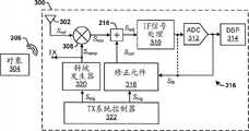
图3是具有带有信号修正元件318的反馈路径316的公开FMCW(调频连续波)雷达系统300的框图,信号修正元件318被配置成生成从反射信号Sref去除不期望信号分量的修正信号Scor。3 is a block diagram of a disclosed FMCW (Frequency Modulated Continuous Wave)
FMCW雷达系统300包括被配置成接收从对象304反射的电磁信号306的一个或多个接收天线302。在一些实施例中,所述一个或多个接收天线302可以包括被配置成接收电磁信号306的单个天线。在其他实施例中,所述一个或多个接收天线302可以包括具有多个天线的天线阵列,其中,相应天线被配置成接收电磁信号306的不同频道。FMCW
FMCW雷达系统300还包括斜坡信号发生器320,其被配置成生成具有连续变化频率斜坡(例如,锯齿波形)的多个斜坡信号。斜坡信号发生器320由被配置成定义斜坡信号的一个或多个参数的发射系统控制器322来控制。包括所述多个斜坡信号中的一个的斜坡信号Sramp被提供给发射路径TX,其从FMCW雷达系统300且向位于接收路径内的接收混频器308发射信号。接收混频器308还接收基于电磁信号306的反射信号Sref,并且将反射信号Sref与斜坡信号Sramp混合。将反射信号Sref与斜坡信号Sramp混合提供具有与FMCW雷达系统300与对象304之间的距离成比例的频率的混合信号Smix。The
混合信号Smix被提供给IF信号处理元件310。IF信号处理元件310可以包括调制元件、一个或多个放大器以及一个或多个滤波元件。IF信号处理元件310被配置成生成已放大、向下变频混合信号Smix',其被输入到被配置成将混合信号Smix'从模拟信号转换成数字信号的模数转换器(ADC)312。该数字信号被提供给被配置成处理数字信号以确定对象304的位置的数字信号处理器314。The mixed signal Smix is supplied to the IF
已放大、向下变频混合信号Smix'还被提供给向信号修正元件318提供反馈信号Sfb的反馈路径316。反馈路径316从在接收混频器308下游的接收路径中的位置延伸到信号修正元件318。在一些实施例中,反馈路径316可以从IF信号处理元件310的输出端延伸到信号修正元件318。在其他实施例中,反馈路径316可以从ADC 312的输出端延伸到信号修正元件318。The amplified, down-converted mix signal Smix ′ is also provided to a
信号修正元件318被配置成从反馈路径316接收反馈信号Sfb,并从发射系统控制器322接收触发信号Strig,其指示斜坡信号Sramp的变化。基于触发信号Strig和反馈信号Sfb,信号修正元件318被配置成确定与由触发信号Strig指示的斜坡信号相对应的混合信号Smix(例如,低频和/或DC分量)的不期望信号分量。例如,信号修正元件318可以在一段时间内执行反馈信号Sfb的测量扫描以确定与由触发信号Strig指示的斜坡信号相对应的混合信号的不期望信号分量。The
信号修正元件318被配置成存储与不同斜坡信号的不期望信号分量相对应的补偿参数。例如,信号修正元件318被配置成存储与第一斜坡信号的不期望信号分量相对应的补偿参数、与第二斜坡信号的不期望信号分量相对应的补偿参数等。通过存储与不同斜坡信号的不期望信号分量相对应的补偿参数,信号修正元件318能够生成修正信号Scor,其基于来自斜坡信号的前一测量扫描的信号信息来减少不期望信号分量。The
例如,如果发射系统控制器322输出对应于第一斜坡信号的触发信号Strig,则斜坡信号发生器320将输出提供给接收混频器308的第一斜坡信号。触发信号Strig向信号修正元件318指示正在接收第一斜坡信号。如果斜坡信号发生器320先前已使用第一斜坡信号,则信号修正元件318将已存储与来自前一测量扫描的第一斜坡信号相对应的补偿参数。因此,在接收到触发信号Strig时,信号修正元件318将基于对应于第一斜坡信号的存储补偿参数来生成非零修正信号。替换地,如果斜坡信号发生器320先前未使用第一斜坡信号(即,如果斜坡信号第一次使用),则信号修正元件318将未存储对应于第一斜坡信号的补偿参数且将不会生成非零修正信号。相反,信号修正元件318将在第一斜坡信号的测量扫描结束时计算一个或多个补偿参数,并将存储补偿参数以在第一斜坡信号被再次使用时使用。For example, if the transmit
修正信号被提供给加法器216,其被配置成用混合信号Smix减去修正信号Scor以生成具有减少的不期望信号分量的已调整信号Sadj。在一些实施例中,加法器216位于IF信号处理元件310的上游。通过在IF信号处理之前消除不期望信号分量,能够将IF信号处理的增益设置得较高,将允许更好地利用中频(IF)信号处理级。The correction signal is provided to an
因此,FMCW雷达系统300的发射机和接收路径之间的基本上恒定的耦合路径允许信号修正元件318生成与斜坡信号的不期望信号分量相关联的补偿参数,并在斜坡信号随后被用来访问补偿参数时实时地生成修正信号。Thus, the substantially constant coupling path between the transmitter and receive paths of the
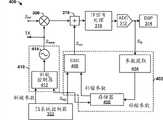
图4图示出公开FMCW雷达系统400的一些实施例的更详细框图。FMCW雷达系统400包括斜坡信号发生器410和信号修正元件402。FIG. 4 illustrates a more detailed block diagram of some embodiments of a disclosed
斜坡信号发生器410包括斜坡控制器412和受控振荡器414。斜坡控制器412被配置成从发射系统控制器322接收一个或多个斜坡参数和触发信号Strig。所述一个或多个斜坡参数将由受控振荡器414生成的斜坡信号Sramp。基于所述一个或多个斜坡参数,斜坡控制器412被配置成操作受控振荡器414以生成斜坡信号Sramp,其被提供给发射路径TX和位于接收路径内的接收混频器308。触发信号Strig指示斜坡信号Sramp的变化。The
信号修正元件402包括参数提取元件404、存储元件406以及修正信号发生器408。The
参数提取元件404被配置成从接收路径接收反馈信号Sfb并基于包括反馈信号Sfb的时间区段(例如,反馈信号是2 us区段)的测量扫描来生成一个或多个补偿参数。所述一个或多个补偿参数被提供给存储元件406,其被配置成存储对应于与斜坡信号Sramp相关联的不期望信号分量的一个或多个补偿参数。例如,存储元件406被配置成存储对应于与第一斜坡信号相关联的不期望信号分量的一个或多个补偿参数、对应于与第二斜坡信号相关联的不期望信号分量的一个或多个补偿参数等。The
在一些实施例中,存储元件406可以包括被配置成当FMCW雷达系统100未被供电时存储一个或多个补偿参数的非易失性存储器。在这种实施例中,当向FMCW雷达系统100提供功率时,可以使用从FMCW雷达系统100的先前操作存储在存储元件406中的一个或多个补偿参数来立即去除接收到的反射信号的不期望信号分量。在一些实施例中,可以最初将一个或多个补偿参数预先加载到存储元件406中(例如,基于预先制造的模拟或测试数据)并随后基于反馈信号Sfb进行更新。In some embodiments,
在一些实施例中,对应于斜坡信号的所述一个或多个补偿参数可以包括在多个测量扫描内确定的补偿参数的平均值。例如,如果对包括已存储补偿参数的斜坡信号的反射信号执行测量扫描,则存储元件406能够存储已存储补偿参数和根据测量扫描确定的新补偿参数的平均值。In some embodiments, the one or more compensation parameters corresponding to the ramp signal may comprise an average value of compensation parameters determined over a plurality of measurement scans. For example, if a measurement scan is performed on the reflected signal of a ramp signal comprising stored compensation parameters, the
修正信号发生器408被配置成从发射系统控制器322接收触发信号Strig并从存储元件406接收斜坡信号Sramp接收对应于斜坡信号Sramp的一个或多个补偿参数。基于所述一个或多个补偿参数,修正信号发生器408被配置成生成对混合信号中的不期望信号分量(例如,低频或DC信号分量)负责的修正信号Scor。The
在各种实施例中,修正信号Scor可以包括具有任何阶多项式函数的多项式修正信号。例如,在一些实施例中,修正信号Scor可以包括一阶多项式函数(例如,常数或线性斜坡信号),而在其他实施例中,修正信号Scor可以包括二阶或更高阶多项式函数。在其他实施例中,修正信号Scor可以包括其他函数,例如,诸如谐波函数(例如,正弦和余弦函数)。In various embodiments, the correction signal Scor may comprise a polynomial correction signal having a polynomial function of any order. For example, in some embodiments, the correction signal Scor may include a first order polynomial function (eg, a constant or linear ramp signal), while in other embodiments the correction signal Scor may include a second or higher order polynomial function. In other embodiments, the correction signal Scor may include other functions, such as, for example, harmonic functions (eg, sine and cosine functions).
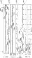
图5A—5B图示出示出了具有带有信号修正元件的反馈路径的公开FMCW雷达系统的操作的图表。图表500、506、510和514图示出对未存储补偿参数的反射信号进行操作的公开FMCW雷达系统。图表516、522、526和532图示出对已存储补偿参数的反射信号进行操作的公开FMCW雷达系统。5A-5B illustrate diagrams showing the operation of the disclosed FMCW radar system having a feedback path with a signal correction element.
图表500图示出用于具有2个单元的归一化时间的反射信号的测量扫描的作为时间(x轴)的函数的反射信号(y轴)的信号强度。如图表500中所示,反射信号包括四个频道502a—502d。四个频道502a—502d中的每一个的信号强度具有高频分量和低频和/或DC分量。例如,频道502c具有低频分量,其具有约1.4单元的半周期。图表500还图示出修正信号504。由于未针对反射信号502的斜坡信号存储补偿参数,所以修正信号504具有零的恒定值。The
图表506图示出已根据作为时间(x轴)的函数的修正信号504(y轴)进行调整的反射信号的信号强度。如图表506中所示,由于修正信号504具有零的恒定值,所以图表508a—508d中的已调整信号的信号强度等于图表500中的反射信号的信号强度。
图表510图示出已根据作为频率(x轴)的函数的修正信号504(y轴)进行调整的反射信号的信号强度。如图表510中所示,反射信号512a—512d在低频下且在对应于不期望信号分量的DC频率下具有高信号强度。
图表514图示出由作为频率(x轴)的函数的修正信号504(y轴)提供的信号电平的下降。如图表514中所示,由于修正信号504具有零的恒定值,所以在任何频率下都不调整反射信号的信号电平。
图表516图示出用于反射信号的测量扫描的作为时间(x轴)的函数的反射信号(y轴)的信号强度。如图表516中所示,反射信号包括具有高频分量和低频和/或DC分量的四个频道518a—518d。图表516还图示出用于四个频道中的每一个的修正信号520a—520d。例如,选择第一修正信号520a以减少第一频道518a中的反射信号的不期望低频信号,选择第二修正信号520b以减少第二频道518b中的反射信号的不期望低频信号等。由于为反射信号518的斜坡信号存储了补偿参数,所以修正信号520a—520d具有非零值。
图表522图示出已根据作为时间(x轴)的函数的修正信号520a—520d(y轴)来调整的已调整信号的信号强度。由于修正信号520a—520d具有非零值,所以其减少了不期望信号分量,导致用于四个通道中的每一个的已调整信号524a—524d,所述四个通道具有小于图表516中的反射信号的信号强度。
图表526图示出作为频率(x轴)的函数的已调整信号(y轴)的信号强度。如图表526中所示,在低频下且在相对于未调整信号528a—528d的DC频率下降低已调整信号530a—530d的信号电平,但是其在较高频率下相对未改变。因此,修正信号520a—520d在不改变较高频率有用信号分量的情况下精确地减少不期望低频和DC信号分量。
图表530图示出由作为频率(x轴)的函数的修正信号520a—520d(y轴)提供的信号电平的下降。如图表530中所示,已调整信号530a—530d的信号电平对于DC信号而言被降低约20至30 dB之间且对于低频信号而言降低较小的量。此外,针对较高频率,未降低已调整信号530a—530d的信号电平。Graph 530 illustrates the reduction in signal level provided by
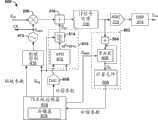
图6A是具有反馈路径的公开FMCW雷达系统600的框图,该反馈路径包括被配置成生成修正信号Scor的模拟多项式发生器610,该修正信号Scor对反射信号中的不期望信号分量负责。FIG. 6A is a block diagram of adisclosed FMCW radar system 600 with a feedback path including an analog polynomial generator 610 configured to generate a correction signal S corresponsible for undesired signal components in reflected signals.
反馈路径包括IF(中频)参数提取元件602。IF参数提取元件602被配置成将反射信号的接收测量扫描时间划分成相等数目的区段,将各区段内的信号加和,并根据该和而生成一个或多个补偿参数。此外,在一些实施例中,IF参数提取元件602被配置成将接收信号划分成四个相等时域四分之一。IF参数提取元件602然后将各四分之一内的信号加和并根据该和来计算用于平方律多项式修正信号的补偿参数。The feedback path includes an IF (intermediate frequency)
在一些实施例中,IF参数提取元件602包括被连接到累加器606的加法器604。反馈路径从累加器606的输出端延伸到加法器604的输入端,使得累加器606的输出被加到由加法器604接收到的反馈信号Sfb。通过将累加器606的输出加到反馈信号Sfb,累加器606将反射信号加和以生成用于测量扫描的一个或多个部分和Qn。所述一个或多个部分和Qn被提供给补偿参数计算元件608,其被配置成根据所述部分和Qn来计算一个或多个补偿参数。In some embodiments, the IF
在一些实施例中,累加器606被配置成从发射系统控制器616接收重置信号Sreset。重置信号Sreset以将在时域中将测量扫描分离成多个区段的方式将累加器606的值重置。通过将测量扫描分离成多个区段,针对每个区段生成部分和Qn。在一些实施例中,重置信号包括触发信号Strig。In some embodiments, the
在一个实施例中,IF参数提取元件602被配置成生成用于二阶多项式修正信号的第一、第二和第三补偿参数(a、b和c)。在这种实施例中,IF参数提取元件602将测量扫描分离成四个四分之一。累加器606被配置成生成用于测量扫描的四个四分之一的部分和Q1—Q4。部分和Q1—Q4被提供给补偿参数计算元件608,其如下确定补偿参数:In one embodiment, the IF
a = -Q1-Q2+Q3+Q4,a = -Q1 -Q2 +Q3 +Q4 ,
b = 2*(Q1-Q2-Q3+Q4),以及b = 2*(Q1 -Q2 -Q3 +Q4 ), and
c = 1/6 (-Q1+7*Q2+7*Q3-Q4)。c = 1/6 (-Q1 +7*Q2 +7*Q3 -Q4 ).
IF参数提取元件602被配置成将所述一个或多个补偿参数写入存储元件618,其被配置成存储对应于各种斜坡信号的一个或多个补偿参数。在一些实施例中,可以将存储元件618包括在发射系统控制器616内。The IF
发射系统控制器616被配置成经由被配置成将补偿参数从数字信号转换成模拟信号的数模转换器(DAC)609将对应于斜坡信号Sramp的一个或多个补偿参数提供给模拟多项式发生器612。模拟多项式发生器612被配置成生成包括多项式函数的模拟修正信号Scor。模拟修正信号Scor可以在被提供给加法器216之前由滤波元件614进行滤波,其用混合信号Smix减去修正信号Scor以减少不期望信号分量。The
图6B是被配置成生成二次多项式(例如,at2 + bt + c))的模拟多项式发生器620的一些实施例的框图。FIG. 6B is a block diagram of some embodiments of an analog
模拟多项式发生器620包括第一模拟累加器622、第一加法器624、第二模拟累加器626以及第二加法器628。第一累加器622被配置成接收初始化信号(例如,触发信号Strig)和第一补偿参数a。在接收到初始化信号时,第一累加器622开始在时间上对a的值求积分以生成具有at的值的信号。第一加法器624被配置成将第一累加器622的输出与第二补偿参数b相加以生成具有at+b的值的信号。第二累加器626被配置成接收初始化信号和具有at+b的值的信号。在接收到初始化信号时,第二累加器626开始在时间上对at+b的值求积分以生成具有at2+bt的值的信号。第二加法器628被配置成将第二累加器626的输出与第三补偿参数c相加以生成包括具有at2 + bt + c的值的二阶多项式的修正信号Scor。The analog
图7A是具有反馈路径的公开FMCW雷达系统700的框图,该反馈路径包括被配置成生成修正信号Scor的模拟多项式发生器704,该修正信号Scor对反射信号中的不期望信号分量负责。7A is a block diagram of a disclosedFMCW radar system 700 having a feedback path including an analog polynomial generator 704 configured to generate a correction signal S corresponsible for an undesired signal component in the reflected signal.
数字多项式发生器704被配置成从存储元件618接收一个或多个补偿参数并根据所述一个或多个补偿参数生成包括多项式函数的数字修正信号Scor。该数字修正信号Scor被提供给数模转换器706,其被配置成将数字修正信号Scor转换成模拟信号。该模拟信号可以在被提供给加法器216之前由滤波元件614进行滤波,其用混合信号Smix减去修正信号Scor以减少不期望信号分量。Digital polynomial generator 704 is configured to receive one or more compensation parameters from
图7B是数字多项式发生器708的一些实施例的框图。数字多项式发生器708包括第一加法器710、第一数字累加器712、第二加法器714、第三加法器716、第二数字累加器718以及第四加法器720。第一加法器710被配置成接收初始信号init(例如,触发信号Strig)和第一输入参数p2。第一加法器710具有连接到第一累加器712的输入节点的输出节点。反馈路径从第一累加器712的输出节点延伸至第一加法器710的输入节点,以生成具有p2t的值的信号。第二加法器714被配置成将第二输入参数p1与具有p2t的值的信号相加以生成具有p2t + p1的值的信号。第二加法器714具有连接到第三加法器716的输入节点的输出节点。第三加法器716具有连接到第二累加器718的输入节点的输出节点。反馈路径从第二累加器718的输出节点延伸到第三加法器716的输入节点,以生成具有1/2p2t2 - 1/2p2t + p1t的值的信号。第四加法器720具有连接到第二累加器718的输出节点的输入节点并被配置成将第三输入参数p0与具有1/2p2t2 - 1/2p2t + p1t的值的信号相加,以生成具有值1/2p2t2 -1/2p2t + p1t + p0的输出信号。FIG. 7B is a block diagram of some embodiments of a digital polynomial generator 708 . The digital polynomial generator 708 includes a first adder 710 , a first
为了实现具有形式at2 + bt + c的输出信号,参数转换元件722被配置成接收补偿参数a、b和c并根据递归关系来执行系数的置换,如本领域的技术人员众所周知的。更特别地,参数转换元件722被配置成通过如下根据a、b和c来计算用于数字多项式发生器508的输入参数p0、p1以及p2而利用递归关系以便获得具有的形式at2 + bt + c的二阶多项式: To achieve an output signal of the format2 +bt+c, the
p0 = cp0 = c
p1 = a+bp1 = a+b
p2 = 2*ap2 = 2*a
输入参数p0、p1和p2被馈送到数字多项式发生器508,使得数字多项式发生器708在不增加系统的计算的情况下计算具有at2 + bt + c形式的多项式的输出信号。The input parameters p0 , p1 and p2 are fed to the digital polynomial generator 508 such that the digital polynomial generator 708 computes an output signal having a polynomial of the form at2 + bt + c without increasing the calculations of the system.
图8是减少FMCW雷达系统中的不期望信号分量(例如,低频和DC信号分量)的示例性方法800的流程图。FIG. 8 is a flowchart of an
将认识到的是虽然将方法800示为并描述为一系列的动作或事件,但不应在限制性意义上解释此类动作或事件的所示排序。例如,某些动作可以按照不同的顺序和/或与除本文中所示和/或所述那些之外的其他动作或事件同时地发生。另外,可能并不是需要所有所示动作以实现本文公开的一个或多个方面或实施例。并且,可以在一个或多个单独动作和/或阶段中执行本文所描述的动作中的一个或多个。It will be appreciated that while
在802处,接收具有不期望信号分量的反射信号。该反射信号包括从雷达系统发射的信号,其已被从对象反射并返回至雷达系统。At 802, a reflected signal having an undesired signal component is received. The reflected signal includes a signal emitted from the radar system that has been reflected from the object and returned to the radar system.
在804处,将反射信号与具有连续变化频率斜坡的斜坡信号混合。在一些实施例中,斜坡信号可以包括锯齿波形。At 804, the reflected signal is mixed with a ramp signal having a continuously varying frequency ramp. In some embodiments, the ramp signal may include a sawtooth waveform.
在一些实施例中,方法800可以在806处进行检查以确定对应于斜坡信号的一个或多个补偿参数是否被存储在存储器中(例如,从先前的测量扫描)。在其他实施例中,其中,所述一个或多个补偿参数已被预先加载到存储器中,可以跳过动作806—810。In some embodiments,
如果对应于斜坡信号的补偿参数未被存储在存储器中,则该方法前进至812。If compensation parameters corresponding to the ramp signal are not stored in memory, the method proceeds to 812 .
如果对应于斜坡信号的补偿参数被存储在存储器中,则在808处,可以从对应于斜坡信号的一个或多个存储补偿参数选择性地生成修正信号。在810处,从混合信号减去修正信号。该修正信号减少混合信号中的不期望频率分量(例如,低频和/或DC分量)。在各种实施例中,修正信号可以包括多项式函数或谐波函数。If compensation parameters corresponding to the ramp signal are stored in memory, at 808 a correction signal may be selectively generated from the one or more stored compensation parameters corresponding to the ramp signal. At 810, the correction signal is subtracted from the mixed signal. The correction signal reduces undesired frequency components (eg, low frequency and/or DC components) in the mixed signal. In various embodiments, the correction signal may comprise a polynomial function or a harmonic function.
在812处,生成对应于不期望信号分量的一个或多个补偿参数。At 812, one or more compensation parameters corresponding to the undesired signal components are generated.
在一些实施例中,在814处,通过将混合信号的测量扫描(在804处生成的混合信号的时间区段)划分成许多相等的时域区段来生成补偿参数。在816处,对相等时域区段中的每一个中的信号求积分以生成等于相等时域区段的数目的许多部分和。然后在818处对该部分和进行数学运算以生成所述一个或多个补偿参数。In some embodiments, at 814, the compensation parameters are generated by dividing the measurement sweep of the mixed signal (time segments of the mixed signal generated at 804) into a number of equal time domain segments. At 816, the signal in each of the equal time domain bins is integrated to generate a number of partial sums equal to the number of equal time domain bins. The partial sum is then mathematically operated at 818 to generate the one or more compensation parameters.
在820处,存储对应于该斜坡信号的一个或多个补偿参数。At 820, one or more compensation parameters corresponding to the ramp signal are stored.
该方法可以在多个测量扫描内重复。在为斜坡信号存储一个或多个补偿参数之后(820),可以在808处根据一个或多个存储补偿参数来确定对应于斜坡信号的修正信号。The method can be repeated over multiple measurement scans. After storing the one or more compensation parameters for the ramp signal (820), a correction signal corresponding to the ramp signal may be determined at 808 based on the one or more stored compensation parameters.
将认识到的是基于本说明书和附图的阅读和/或理解,本领域的技术人员可以想到等价的变更和/或修改。本文中的公开包括所有此类修改和变更,并且一般并不意图从而被限制。例如,虽然公开系统被示为具有两个偏移修正电路和两个反馈环路,但本领域的技术人员将认识到公开系统可以包括两个以上偏移修正电路和/或反馈环路。It will be appreciated that equivalent alterations and/or modifications will occur to those skilled in the art upon a reading and/or understanding of this specification and the accompanying drawings. The disclosure herein includes all such modifications and alterations and is generally not intended to be limiting thereby. For example, although the disclosed system is shown with two offset correction circuits and two feedback loops, those skilled in the art will recognize that the disclosed system may include more than two offset correction circuits and/or feedback loops.
另外,虽然已相对于多个实施方式中的仅一个公开的特定特征或方面,但可以根据需要将此类特征或方面与其他实施方式的一个或多个其他特征和/或方面组合。此外,在本文中使用术语“包括”、“具有”、“有”“带有”和/或其变体的程度上,此类术语意图在意义上是包括性的—类似“包括”。并且,“示例性”仅仅以图意指示例而不是最好的。还应认识到的是出于理解的简单和容易的目的用相对于彼此的特定尺寸和/或取向图示出本文中所述的特征、层和/或元件,并且实际尺寸和/或取向可以基本上与本文中所示的不同。 Additionally, although a particular feature or aspect has been disclosed with respect to only one of the embodiments, such feature or aspect may be combined with one or more other features and/or aspects of other embodiments, as desired. Furthermore, to the extent the terms "including," "having," "having," "with," and/or variations thereof are used herein, such terms are intended to be inclusive in sense—like "comprising." Also, "exemplary" is only intended to indicate an example rather than the best. It should also be appreciated that features, layers and/or elements described herein are shown with particular dimensions and/or orientations relative to one another for simplicity and ease of understanding, and that actual dimensions and/or orientations may Basically different from what is shown in this article. the
Claims (20)
Applications Claiming Priority (2)
| Application Number | Priority Date | Filing Date | Title |
|---|---|---|---|
| US13/710963 | 2012-12-11 | ||
| US13/710,963US9151827B2 (en) | 2012-12-11 | 2012-12-11 | Compensating slowly varying if DC offsets in receivers |
Publications (2)
| Publication Number | Publication Date |
|---|---|
| CN103869294Atrue CN103869294A (en) | 2014-06-18 |
| CN103869294B CN103869294B (en) | 2016-10-05 |
Family
ID=50778305
Family Applications (1)
| Application Number | Title | Priority Date | Filing Date |
|---|---|---|---|
| CN201310668411.3AExpired - Fee RelatedCN103869294B (en) | 2012-12-11 | 2013-12-11 | Compensate the slowly varying intermediate frequency DC skew in receiver |
Country Status (3)
| Country | Link |
|---|---|
| US (1) | US9151827B2 (en) |
| CN (1) | CN103869294B (en) |
| DE (1) | DE102013113859A1 (en) |
Cited By (1)
| Publication number | Priority date | Publication date | Assignee | Title |
|---|---|---|---|---|
| TWI677699B (en)* | 2017-08-10 | 2019-11-21 | 新加坡商聯發科技(新加坡)私人有限公司 | A method and apparatus for generating a beacon signal |
Families Citing this family (9)
| Publication number | Priority date | Publication date | Assignee | Title |
|---|---|---|---|---|
| DE102010030628A1 (en)* | 2010-06-29 | 2011-12-29 | Robert Bosch Gmbh | Radar sensor for motor vehicles |
| US9151827B2 (en)* | 2012-12-11 | 2015-10-06 | Infineon Technologies Ag | Compensating slowly varying if DC offsets in receivers |
| KR101465370B1 (en)* | 2013-12-09 | 2014-11-26 | 한국항공우주연구원 | Apparatus and method of generating of direct digital synthesizer chirp signal using phase accumulation polynomial |
| KR20150134126A (en)* | 2014-05-21 | 2015-12-01 | 재단법인대구경북과학기술원 | Method and apparatus for processing radar signal |
| US10725150B2 (en) | 2014-12-23 | 2020-07-28 | Infineon Technologies Ag | System and method for radar |
| GB2544753B (en)* | 2015-11-24 | 2021-12-08 | Trw Ltd | Transceiver Circuits |
| KR102582054B1 (en)* | 2016-03-31 | 2023-09-25 | 한국전자통신연구원 | Pulse radar apparatus and method for operating pulse radar apparatus |
| WO2019218092A1 (en)* | 2018-05-18 | 2019-11-21 | Polyvalor, Limited Partnership. | Fundamental-and-harmonics multi-frequency doppler radar system with radar motion cancellation |
| TWI734252B (en)* | 2019-11-08 | 2021-07-21 | 立積電子股份有限公司 | Radar and method of updating background components of echo signal for radar |
Citations (6)
| Publication number | Priority date | Publication date | Assignee | Title |
|---|---|---|---|---|
| US4593287A (en)* | 1982-09-30 | 1986-06-03 | The Boeing Company | FM/CW sweep linearizer and method therefor |
| US4760319A (en)* | 1987-02-27 | 1988-07-26 | Magnetic Peripherals Inc. | Circuit for removing unwanted slope transitions from an incoming signal |
| US5068663A (en)* | 1991-01-24 | 1991-11-26 | Valentine Research, Inc. | Motor vehicle radar detector including amplitude detection |
| JP2000065930A (en)* | 1998-08-26 | 2000-03-03 | Nissan Motor Co Ltd | Radar equipment for vehicles |
| US7450051B1 (en)* | 2005-11-18 | 2008-11-11 | Valentine Research, Inc. | Systems and methods for discriminating signals in a multi-band detector |
| WO2012000701A1 (en)* | 2010-06-29 | 2012-01-05 | Robert Bosch Gmbh | Radar sensor for motor vehicles |
Family Cites Families (13)
| Publication number | Priority date | Publication date | Assignee | Title |
|---|---|---|---|---|
| US5990738A (en)* | 1998-06-19 | 1999-11-23 | Datum Telegraphic Inc. | Compensation system and methods for a linear power amplifier |
| US6054896A (en)* | 1998-12-17 | 2000-04-25 | Datum Telegraphic Inc. | Controller and associated methods for a linc linear power amplifier |
| US6054894A (en)* | 1998-06-19 | 2000-04-25 | Datum Telegraphic Inc. | Digital control of a linc linear power amplifier |
| JP4223767B2 (en)* | 2002-08-30 | 2009-02-12 | 富士通株式会社 | Crossover detection method, radar apparatus, and crossover detection program |
| US8195103B2 (en)* | 2006-02-15 | 2012-06-05 | Texas Instruments Incorporated | Linearization of a transmit amplifier |
| US8203481B2 (en)* | 2006-10-06 | 2012-06-19 | Adc Automotive Distance Control Systems Gmbh | Radar system for detecting the surroundings with compensation of interfering signals |
| JP4977443B2 (en)* | 2006-10-31 | 2012-07-18 | 日立オートモティブシステムズ株式会社 | Radar apparatus and radar detection method |
| KR100743965B1 (en) | 2007-05-11 | 2007-08-01 | 쓰리에이로직스(주) | Demodulator capable of compensating offset voltage of RF signal and its method |
| US7737885B2 (en) | 2007-08-01 | 2010-06-15 | Infineon Technologies Ag | Ramp linearization for FMCW radar using digital down-conversion of a sampled VCO signal |
| US8068804B2 (en) | 2008-12-29 | 2011-11-29 | Intel Corporation | Receiver local oscillator leakage compensation in the presence of an interferer |
| DE102011115309A1 (en)* | 2011-09-29 | 2013-04-04 | Infineon Technologies Ag | Radar circuit, radar system and method for testing a connection between a radar circuit and a radar antenna in a vehicle |
| US8867660B2 (en)* | 2011-12-15 | 2014-10-21 | Intel Mobile Communications GmbH | Method and system to measure and compensate undue DCO frequency peaks at GFSK ramp down |
| US9151827B2 (en)* | 2012-12-11 | 2015-10-06 | Infineon Technologies Ag | Compensating slowly varying if DC offsets in receivers |
- 2012
- 2012-12-11USUS13/710,963patent/US9151827B2/enactiveActive
- 2013
- 2013-12-11CNCN201310668411.3Apatent/CN103869294B/ennot_activeExpired - Fee Related
- 2013-12-11DEDE102013113859.4Apatent/DE102013113859A1/ennot_activeWithdrawn
Patent Citations (6)
| Publication number | Priority date | Publication date | Assignee | Title |
|---|---|---|---|---|
| US4593287A (en)* | 1982-09-30 | 1986-06-03 | The Boeing Company | FM/CW sweep linearizer and method therefor |
| US4760319A (en)* | 1987-02-27 | 1988-07-26 | Magnetic Peripherals Inc. | Circuit for removing unwanted slope transitions from an incoming signal |
| US5068663A (en)* | 1991-01-24 | 1991-11-26 | Valentine Research, Inc. | Motor vehicle radar detector including amplitude detection |
| JP2000065930A (en)* | 1998-08-26 | 2000-03-03 | Nissan Motor Co Ltd | Radar equipment for vehicles |
| US7450051B1 (en)* | 2005-11-18 | 2008-11-11 | Valentine Research, Inc. | Systems and methods for discriminating signals in a multi-band detector |
| WO2012000701A1 (en)* | 2010-06-29 | 2012-01-05 | Robert Bosch Gmbh | Radar sensor for motor vehicles |
Cited By (3)
| Publication number | Priority date | Publication date | Assignee | Title |
|---|---|---|---|---|
| TWI677699B (en)* | 2017-08-10 | 2019-11-21 | 新加坡商聯發科技(新加坡)私人有限公司 | A method and apparatus for generating a beacon signal |
| US11237649B2 (en) | 2017-08-10 | 2022-02-01 | Mediatek Singapore Pte. Ltd. | Inductive beacon for time-keying virtual reality applications |
| US11726585B2 (en) | 2017-08-10 | 2023-08-15 | Mediatek Singapore Pte. Ltd. | Inductive beacon for time-keying virtual reality applications |
Also Published As
| Publication number | Publication date |
|---|---|
| DE102013113859A1 (en) | 2014-06-12 |
| CN103869294B (en) | 2016-10-05 |
| US9151827B2 (en) | 2015-10-06 |
| US20140159943A1 (en) | 2014-06-12 |
Similar Documents
| Publication | Publication Date | Title |
|---|---|---|
| CN103869294B (en) | Compensate the slowly varying intermediate frequency DC skew in receiver | |
| CN107923972B (en) | Chirp frequency non-linear mitigation in radar systems | |
| US7737885B2 (en) | Ramp linearization for FMCW radar using digital down-conversion of a sampled VCO signal | |
| CN102395899B (en) | Systems Using Direct Digital Synthesizers | |
| US10145937B2 (en) | Dynamic IQ mismatch correction in FMCW radar | |
| JP5566974B2 (en) | Signal generation circuit, oscillation device, radar device | |
| JP6663115B2 (en) | FMCW radar | |
| US7982663B2 (en) | Digital signal processor | |
| CN107250833A (en) | Radar installations | |
| CN102655403A (en) | A time base generator and method for providing a first clock signal and a second clock signal | |
| JP2011196880A (en) | Fmcw signal generation circuit and radar apparatus | |
| WO2019234900A1 (en) | Radar device | |
| US10505770B2 (en) | Reception signal processing device, radar, and object detection method | |
| CN103891135B (en) | Timing and Amplitude Adjustment in Envelope Tracking Amplification Stages | |
| US20220260698A1 (en) | Radar distance measuring device and radar distance measuring method | |
| US8897656B2 (en) | Synchronizing phases of multiple opitcal channels | |
| JP2011127923A (en) | Radar system | |
| CN113614560B (en) | Programmable millimeter wave radar integrated circuit | |
| GB2547551A (en) | An electronic circuit | |
| Ali et al. | Design and implementation of FMCW radar using the raspberry Pi single board computer | |
| WO2011088278A3 (en) | Low phase noise rf signal generating system and method for calibrating phase noise measurement systems using same | |
| Carlowitz et al. | A low power Pulse Frequency Modulated UWB radar transmitter concept based on switched injection locked harmonic sampling | |
| Payne et al. | A synchronised direct digital synthesiser | |
| HK1168904B (en) | System employing a direct digital synthesiser |
Legal Events
| Date | Code | Title | Description |
|---|---|---|---|
| C06 | Publication | ||
| PB01 | Publication | ||
| C10 | Entry into substantive examination | ||
| SE01 | Entry into force of request for substantive examination | ||
| C14 | Grant of patent or utility model | ||
| GR01 | Patent grant | ||
| CF01 | Termination of patent right due to non-payment of annual fee | Granted publication date:20161005 Termination date:20191211 | |
| CF01 | Termination of patent right due to non-payment of annual fee |