CN103854595A - Writing apparatus, light emitting diode display panel, and emitter - Google Patents
Writing apparatus, light emitting diode display panel, and emitterDownload PDFInfo
- Publication number
- CN103854595A CN103854595ACN201210498002.9ACN201210498002ACN103854595ACN 103854595 ACN103854595 ACN 103854595ACN 201210498002 ACN201210498002 ACN 201210498002ACN 103854595 ACN103854595 ACN 103854595A
- Authority
- CN
- China
- Prior art keywords
- light source
- signal
- display panel
- transmitter
- control circuit
- Prior art date
- Legal status (The legal status is an assumption and is not a legal conclusion. Google has not performed a legal analysis and makes no representation as to the accuracy of the status listed.)
- Pending
Links
Images

Landscapes
- Control Of Indicators Other Than Cathode Ray Tubes (AREA)
Abstract
Translated fromChineseDescription
Translated fromChinese技术领域technical field
本发明涉及一种书写装置及其发光二极管显示板及发射器。The invention relates to a writing device, a light-emitting diode display panel and a transmitter thereof.
背景技术Background technique
传统的黑板是利用粉笔在玻璃质的平板上书写,书写或擦拭过程中产生大量的粉层。该粉层不但污染环境,甚至直接提高使用者的呼吸道疾病病发率。Traditional blackboard is to utilize chalk to write on glassy flat plate, produces a large amount of powder layers in writing or wiping process. The powder layer not only pollutes the environment, but even directly increases the incidence of respiratory diseases of users.
发明内容Contents of the invention
有鉴于此,有必要提供一种无粉尘的书写装置及其发光二极管显示板及发射器。In view of this, it is necessary to provide a dust-free writing device and its LED display panel and emitter.
一种发光二极管显示板,包括由多个像素单元排列组成的阵列及控制各像素单元的控制电路,每个像素单元包括光源及驱动电路,每个像素单元还包括光侦测器,该发光二极管显示板还包括电连接至驱动电路的接收器,接收器根据外界信号输出对光源进行选择的第一信号给控制电路,当一外界光源在该阵列上移动时,相应的像素单元的光侦测器侦测到外界光源的移动而发出第二信号并传递给控制电路,控制电路再根据第一信号及第二信号通过驱动电路点亮相应像素单元的光源,从而使发光二极管显示板上呈现出与外界光源的移动对应的轨迹。A light-emitting diode display panel, including an array composed of a plurality of pixel units and a control circuit for controlling each pixel unit, each pixel unit includes a light source and a driving circuit, each pixel unit also includes a photodetector, the light-emitting diode The display panel also includes a receiver electrically connected to the drive circuit, the receiver outputs the first signal for selecting the light source to the control circuit according to the external signal, when an external light source moves on the array, the light detection of the corresponding pixel unit The device detects the movement of the external light source and sends out a second signal and transmits it to the control circuit, and the control circuit lights up the light source of the corresponding pixel unit through the drive circuit according to the first signal and the second signal, so that the light-emitting diode display panel presents a The trajectory corresponding to the movement of the ambient light source.
一种发射器,配合上述发光二极管显示板使用,该发射器包括模式选择模块、第一发射端以及第二发射端,该第一发射端根据该模式选择模块选择的模式发出信号给接收器,使接收器产生第一信号,该第二发射端发出光信号照射相应像素单元的光侦测器,使光侦测器产生第二信号。A transmitter used in conjunction with the LED display panel above, the transmitter includes a mode selection module, a first transmitter and a second transmitter, the first transmitter sends a signal to the receiver according to the mode selected by the mode selection module, The receiver is made to generate a first signal, and the second transmitting end emits a light signal to irradiate the photodetector of the corresponding pixel unit, so that the photodetector generates a second signal.
一种发射器,用于配合一发光二极管显示板使用,该发光二极管显示板包括由多个像素单元排列组成的阵列及控制各像素单元的控制电路,每个像素单元包括驱动电路及多种可发出不同颜色光的光源,该发射器包括模式选择模块,该模式选择模块包括一一对应该多种可发出不同颜色的光源的多种模式,该发射器还包含第一发射端与第二发射端,当选择该模式选择模块的其中一模式时,该发射器的第一发射端发出点亮该模式对应颜色的光源的第一信号给控制电路,该发射器的第二发射端发出第二信号给该控制电路,该控制电路再根据第一信号及第二信号通过驱动电路点亮相应像素单元的光源。A transmitter for use with a light-emitting diode display panel. The light-emitting diode display panel includes an array composed of a plurality of pixel units and a control circuit for controlling each pixel unit. Each pixel unit includes a drive circuit and various A light source that emits light of different colors. The emitter includes a mode selection module. The mode selection module includes multiple modes corresponding to a variety of light sources that can emit different colors. The emitter also includes a first emitter and a second emitter. terminal, when one of the modes of the mode selection module is selected, the first transmitting terminal of the transmitter sends a first signal to light the light source of the color corresponding to the mode to the control circuit, and the second transmitting terminal of the transmitter sends a second The signal is sent to the control circuit, and the control circuit lights up the light source of the corresponding pixel unit through the driving circuit according to the first signal and the second signal.
一种书写装置,包括发光二极管显示板及与发光二极管显示板配合使用的发射器,该发光二极管显示板包括由多个像素单元排列组成的阵列及控制各像素单元的控制电路,每个像素单元包括驱动电路、光侦测器及多种可发出不同颜色光的光源,该发光二极管显示板还包括电连接至驱动电路的接收器,该发射器包括模式选择模块,该模式选择模块包括一一对应该多种可发出不同颜色的光源的多种模式,该发射器还包含第一发射端及第二发射端,当选择该模式选择模块的其中一模式时,该发射器的第一发射端向该接收器发出点亮该模式对应颜色的光源的第一信号,该发射器的第二发射端发出第二信号给该光侦测器,该接收器与该光侦测器将接收到的第一信号与第二信号输出给控制电路,该控制电路再根据第一信号及第二信号通过驱动电路点亮相应像素单元的光源。A writing device, comprising a light-emitting diode display panel and an emitter used in conjunction with the light-emitting diode display panel, the light-emitting diode display panel includes an array composed of a plurality of pixel units arranged and a control circuit for controlling each pixel unit, each pixel unit It includes a driving circuit, a light detector and a variety of light sources that can emit light of different colors. The LED display panel also includes a receiver electrically connected to the driving circuit. The transmitter includes a mode selection module, and the mode selection module includes one by one Corresponding to the multiple modes that can emit different colors of light sources, the transmitter also includes a first transmitter and a second transmitter. When one of the modes of the mode selection module is selected, the first transmitter of the transmitter Send a first signal to the receiver to light up the light source of the color corresponding to the mode, the second transmitting end of the transmitter sends a second signal to the photodetector, the receiver and the photodetector will receive The first signal and the second signal are output to the control circuit, and the control circuit lights up the light source of the corresponding pixel unit through the driving circuit according to the first signal and the second signal.
由于该发光二极管显示板是通过接收外界信号来控制该像素单元出光的,使用过程中无需用到会产生粉层的物质,避免了粉尘的产生。再有,通过该发射器在该发光二极管显示板上书写,使用者可以在较远距离实现书写,而不必按压即可驱动该像素单元出光。并且使用者可以在距离黑板较近的讲台上与距离黑板较远的其他位置处实现互动。Since the light-emitting diode display panel controls the light output of the pixel unit by receiving external signals, there is no need to use substances that will generate powder layers during use, thereby avoiding the generation of dust. Furthermore, by using the emitter to write on the light-emitting diode display board, the user can realize writing at a relatively long distance, and the pixel unit can be driven to emit light without pressing. And users can interact with other positions farther away from the blackboard on the podium closer to the blackboard.
附图说明Description of drawings
图1是本发明一实施例中的书写装置的示意图。Fig. 1 is a schematic diagram of a writing device in an embodiment of the present invention.
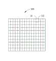
图2是图1所示书写装置中的发光二极管显示板的像素阵列的示意图。FIG. 2 is a schematic diagram of a pixel array of an LED display panel in the writing device shown in FIG. 1 .
图3是图2所示圆圈III的放大图。FIG. 3 is an enlarged view of circle III shown in FIG. 2 .
主要元件符号说明Description of main component symbols
如下具体实施方式将结合上述附图进一步说明本发明。The following specific embodiments will further illustrate the present invention in conjunction with the above-mentioned drawings.
具体实施方式Detailed ways
请参阅图1,本发明的书写装置包括一发光二极管显示板200及与该发光二极管显示板200配合使用的发射器20。请同时参阅图2-3,该发光二极管显示板200包括由多个像素单元10排列组成的阵列100、控制电路(图未示)、接收器30以及配合使用的发射器20。可以理解地,该像素单元10为微单元,该阵列100包含多少个该像素单元10是视该发光二极管显示板200的大小而定,并且单个像素单元10的出光面面积与整块发光二极管显示板200的使用面积的比值越小,则发光二极管显示板200的视觉效果更清晰。Please refer to FIG. 1 , the writing device of the present invention includes an LED display panel 200 and an emitter 20 used in conjunction with the LED display panel 200 . Please refer to FIGS. 2-3 at the same time. The LED display panel 200 includes an
在本实施例中,每一像素单元10包含第一色光源11、第二色光源12、第三色光源13、驱动电路14以及光侦测器15。本实施中该第一色光源11、第二色光源12以及第三色光源13分别为红光光源、绿光光源以及蓝光光源。当然,实际使用时,该第一色光源11、第二色光源12以及第三色光源13各自对应红光光源、绿光光源以及蓝光光源中的一种即可。该第一色光源11、第二色光源12以及第三色光源13的出光由该驱动电路14通过接收到的信号来进行控制。各像素单元10的驱动电路14均与该接收器30连接,以接收控制信号驱动光源发光。该接收器30根据外界信号输出相应的电信号预输入一个选择信号给控制电路。该接收器30包括对应该第一色光源11的第一接收端31、对应该第二色光源12的第二接收端32、对应该第三色光源13的第三接收端33以及第四接收端34。当该接收器30的其中一个或多个接收端接收到信号时,预输入一个或多个选择信号给控制电路,此时控制电路并不输出信号给驱动电路14。换句话说,此时像素单元100并没有被点亮。当像素单元10的光侦测器15同时接收到光信号时,其产生轨迹信号传输给控制电路,控制电路再综合选择信号及轨迹信号进行判断,通过该驱动电路14选择性地点亮该像素单元10中的第一色光源11、第二色光源12以及第三色光源13中的其中一个或多个。In this embodiment, each
该发射器20作为一遥控器,其具有多个模式选择按钮以及发射端。在本实施方式中,该发射器20具有四个按钮以及第一发射端25、第二发射端26两个发射端。该第一发射端25发射红外线控制该接收器30以对控制电路输入选择信号。该第二发射端26发射准直红外光点亮相关的像素单元10。该第一发射端25与该第二发射端26发射不同频率的红外光。该四个按钮分别为控制启动该第一接收端31的第一模式21、控制启动该第二接收端32的第二模式22、控制启动该第三接收端33的第三模式23以及控制启动该第四接收端34的第四模式24,分别对应该像素单元10中的第一色光源11、第二色光源12、第三色光源13以及清除模式。当选择该第一、第二以及第三模式21、22、23时,该第一发射端25向该接收器30传递启动该第一色光源11、第二色光源12以及第三色光源13的信号。同时,该发射器20通过其第二发射端26发出的准直红外光在该阵列100前划出一道轨迹,该轨迹上对应的多个像素单元10的光侦测器14检测到该准直的红外光,进而该多个像素单元10出光呈现出该条轨迹,从而实现在发光二极管显示板200上写字及画画的功能。当该第一、第二以及第三模式21、22、23同时被选择时,该第一、第二以及第三色光源11、12、13均被点亮。像素单元10中的驱动电路14以及光侦测器15只有二者均收到信号,该第一色光源11、第二色光源12以及第三色光源13中的其中一个或多个才会被点亮。每一像素单元10中的光侦测器15设置一侦测阀值,该接收器30设置一接收阀值,限定该光侦测器15所能侦测到的频谱范围异于该接收器30所能接收的频谱范围。也即是该光侦测器15只能侦测到频率在该侦测阀值内的光,该接收器30只能接收到频率在该接收阀值内的光,从而避免外界坏境光的干扰以及第一发射端25与第二反射段26之间的影响。可以理解地,该侦测阈值与该接收阈值不仅限于界定频谱范围,也可以界定光强范围。由于该第一发射端25发射的红外线光束是发散的,所以该第一发射端25发射的红外线传到该发光二极管显示板200时,其强度已减弱至只能满足该接收器30的接收阈值,而不足满足任一像素单元10中的光侦测器15的侦测阈值。而该第二发射端26发出的是强度高于该光侦测器15的阀值的准直红外光,光线到达该发光二级显示板200时仍然保持原有的强度,因此达到该光侦测器15的侦测阈值,从而点亮相应的像素单元10。当然,该侦测阈值与该接收阈值可以同时或者择一界定频谱范围与光强范围。The transmitter 20 is used as a remote controller, which has a plurality of mode selection buttons and a transmitter. In this embodiment, the transmitter 20 has four buttons and two transmitting terminals, a first transmitting terminal 25 and a second transmitting terminal 26 . The first transmitter 25 emits infrared rays to control the receiver 30 to input a selection signal to the control circuit. The second emitting end 26 emits collimated infrared light to light up the
当该发射器20选择第四模式24时,接收器30接收到发射器20的信号而输出部分清除信号给控制电路。该第二发射端26在该阵列100前划出轨迹,各像素单元10的光侦测器14检测到该准直的红外光,进而输出轨迹信号给控制电路。控制电路综合部分清除信号及轨迹信号,控制驱动电路14熄灭对应轨迹的像素单元10,从而实现在发光二极管显示板200的部分清除功能。此外,该第四模式24还可配合第一模式21、第二模式22以及第三模式23对已经点亮的像素单元100中的相应颜色进行选择性地消除。可以理解地,当需要全部清除时,可同时选择该第一模式21、第二模式22、第三模式23以及第四模式24或者直接关闭该第一发射端25。When the transmitter 20 selects the fourth mode 24, the receiver 30 receives the signal from the transmitter 20 and outputs a partial clear signal to the control circuit. The second emitting end 26 draws a track in front of the
由于该发光二极管显示板200是通过接收外界信号来控制该像素单元10出光的,使用过程中无需用到会产生粉层的物质,避免了粉尘的产生。再有,通过该发射器20在该阵列100上书写,使用者可以在较远距离实现书写,而不必按压即可驱动该像素单元10出光。并且使用者可以在距离黑板较近的讲台上与距离黑板较远的其他位置处实现互动。Since the light-emitting diode display panel 200 controls the
Claims (10)
Priority Applications (1)
| Application Number | Priority Date | Filing Date | Title |
|---|---|---|---|
| CN201210498002.9ACN103854595A (en) | 2012-11-29 | 2012-11-29 | Writing apparatus, light emitting diode display panel, and emitter |
Applications Claiming Priority (1)
| Application Number | Priority Date | Filing Date | Title |
|---|---|---|---|
| CN201210498002.9ACN103854595A (en) | 2012-11-29 | 2012-11-29 | Writing apparatus, light emitting diode display panel, and emitter |
Publications (1)
| Publication Number | Publication Date |
|---|---|
| CN103854595Atrue CN103854595A (en) | 2014-06-11 |
Family
ID=50862187
Family Applications (1)
| Application Number | Title | Priority Date | Filing Date |
|---|---|---|---|
| CN201210498002.9APendingCN103854595A (en) | 2012-11-29 | 2012-11-29 | Writing apparatus, light emitting diode display panel, and emitter |
Country Status (1)
| Country | Link |
|---|---|
| CN (1) | CN103854595A (en) |
Cited By (1)
| Publication number | Priority date | Publication date | Assignee | Title |
|---|---|---|---|---|
| CN104183161A (en)* | 2014-08-29 | 2014-12-03 | 国家电网公司 | Electric power training white board with warning function and use method of electric power training white board with warning function |
Citations (10)
| Publication number | Priority date | Publication date | Assignee | Title |
|---|---|---|---|---|
| JPH0448314A (en)* | 1990-06-18 | 1992-02-18 | Omron Corp | Copy board system |
| JPH07319616A (en)* | 1994-05-26 | 1995-12-08 | Hitachi Ltd | Position input method and conference support system using the same |
| CN2377626Y (en)* | 1999-05-18 | 2000-05-10 | 王子亮 | Electronic blackboard |
| JP2001306253A (en)* | 2000-04-18 | 2001-11-02 | Seiko Epson Corp | Image display device |
| CN1971492A (en)* | 2005-11-22 | 2007-05-30 | 弘瀚科技有限公司 | track display touch panel |
| CN101191968A (en)* | 2006-11-27 | 2008-06-04 | 株式会社日立显示器 | Image display device with screen input function |
| CN101872254A (en)* | 2009-04-24 | 2010-10-27 | 鸿富锦精密工业(深圳)有限公司 | Portable handwriting input device |
| CN201907319U (en)* | 2010-07-27 | 2011-07-27 | 河南理工大学 | Touch light-emitting blackboard triggered by human body micro electricity |
| US20110241989A1 (en)* | 2010-04-02 | 2011-10-06 | Samsung Electronics Co., Ltd. | Remote touch panel using light sensor and remote touch screen apparatus having the same |
| CN202033726U (en)* | 2011-04-25 | 2011-11-09 | 北京汇冠新技术股份有限公司 | White board marker |
- 2012
- 2012-11-29CNCN201210498002.9Apatent/CN103854595A/enactivePending
Patent Citations (10)
| Publication number | Priority date | Publication date | Assignee | Title |
|---|---|---|---|---|
| JPH0448314A (en)* | 1990-06-18 | 1992-02-18 | Omron Corp | Copy board system |
| JPH07319616A (en)* | 1994-05-26 | 1995-12-08 | Hitachi Ltd | Position input method and conference support system using the same |
| CN2377626Y (en)* | 1999-05-18 | 2000-05-10 | 王子亮 | Electronic blackboard |
| JP2001306253A (en)* | 2000-04-18 | 2001-11-02 | Seiko Epson Corp | Image display device |
| CN1971492A (en)* | 2005-11-22 | 2007-05-30 | 弘瀚科技有限公司 | track display touch panel |
| CN101191968A (en)* | 2006-11-27 | 2008-06-04 | 株式会社日立显示器 | Image display device with screen input function |
| CN101872254A (en)* | 2009-04-24 | 2010-10-27 | 鸿富锦精密工业(深圳)有限公司 | Portable handwriting input device |
| US20110241989A1 (en)* | 2010-04-02 | 2011-10-06 | Samsung Electronics Co., Ltd. | Remote touch panel using light sensor and remote touch screen apparatus having the same |
| CN201907319U (en)* | 2010-07-27 | 2011-07-27 | 河南理工大学 | Touch light-emitting blackboard triggered by human body micro electricity |
| CN202033726U (en)* | 2011-04-25 | 2011-11-09 | 北京汇冠新技术股份有限公司 | White board marker |
Cited By (2)
| Publication number | Priority date | Publication date | Assignee | Title |
|---|---|---|---|---|
| CN104183161A (en)* | 2014-08-29 | 2014-12-03 | 国家电网公司 | Electric power training white board with warning function and use method of electric power training white board with warning function |
| CN104183161B (en)* | 2014-08-29 | 2016-08-24 | 国家电网公司 | A kind of training on electric power blank with alarm function |
Similar Documents
| Publication | Publication Date | Title |
|---|---|---|
| TWI547834B (en) | Writing apparatus and light-emitting diode display panel and emitting device thereof | |
| JP7226872B2 (en) | Light Emitting Diode Switch Elements and Arrays | |
| US9237632B2 (en) | Illumination lighting apparatus and method of controlling illumination | |
| CN101341798B (en) | Systems and methods for controlling lighting systems | |
| CN101271620B (en) | Laser remote control signal receiver and its matching laser remote control signal transmitter | |
| CN204180216U (en) | Non-touch hand signal recognition device, intelligent terminal remote controller and television set | |
| JP2016535927A (en) | Method and apparatus for controlling illumination | |
| TWI553599B (en) | Writing apparatus and light-emitting diode display panel and writing pen thereof | |
| TW201425071A (en) | Light-emitting diode display panel | |
| CN106797688B (en) | Optical power lighting system | |
| CN103854595A (en) | Writing apparatus, light emitting diode display panel, and emitter | |
| WO2022089125A1 (en) | Button light guide apparatus and method, and aerosol generating apparatus | |
| CN103902072B (en) | Writing device and its light-emitting diode display board and writing pen | |
| US20150351194A1 (en) | OLED Lighting Module and Lighting Apparatus and Interactive Light Wall Using the Same | |
| CN103903522B (en) | Light-emitting diode display panel | |
| CN113267919A (en) | Liquid crystal module, electronic equipment and screen interaction system | |
| TWI564170B (en) | Light-emitting diode blackboard | |
| TW201421293A (en) | Writing apparatus and light-emitting diode display panel and writing pen thereof | |
| CN203039660U (en) | Infrared touch button device used in water outlet mechanism | |
| CN102608612A (en) | Proximity sensor apparatus for a game device | |
| CN103786494B (en) | Light emitting diode blackboard | |
| TW201419052A (en) | Method to use infrared for performing virtual touch control and infrared positioning stylus | |
| EP3580998B1 (en) | Lighting apparatus and system | |
| TWM663241U (en) | Touch panel with luminous decorative line | |
| KR20150102300A (en) | light controlling system |
Legal Events
| Date | Code | Title | Description |
|---|---|---|---|
| C06 | Publication | ||
| PB01 | Publication | ||
| C10 | Entry into substantive examination | ||
| SE01 | Entry into force of request for substantive examination | ||
| WD01 | Invention patent application deemed withdrawn after publication | Application publication date:20140611 | |
| WD01 | Invention patent application deemed withdrawn after publication |