CN103842649A - Solar thermal power generation apparatus - Google Patents
Solar thermal power generation apparatusDownload PDFInfo
- Publication number
- CN103842649A CN103842649ACN201180073894.1ACN201180073894ACN103842649ACN 103842649 ACN103842649 ACN 103842649ACN 201180073894 ACN201180073894 ACN 201180073894ACN 103842649 ACN103842649 ACN 103842649A
- Authority
- CN
- China
- Prior art keywords
- heating
- heat
- gas
- amount
- heating medium
- Prior art date
- Legal status (The legal status is an assumption and is not a legal conclusion. Google has not performed a legal analysis and makes no representation as to the accuracy of the status listed.)
- Pending
Links
- 238000010248power generationMethods0.000titleclaimsabstractdescription120
- 238000010438heat treatmentMethods0.000claimsabstractdescription517
- 239000007789gasSubstances0.000claimsabstractdescription216
- 239000012071phaseSubstances0.000claimsabstractdescription76
- 239000007791liquid phaseSubstances0.000claimsabstractdescription64
- 239000007788liquidSubstances0.000claimsabstractdescription26
- 238000000926separation methodMethods0.000claimsabstractdescription23
- 239000000463materialSubstances0.000claimsdescription77
- 238000005259measurementMethods0.000claimsdescription18
- 238000010521absorption reactionMethods0.000claimsdescription7
- XLYOFNOQVPJJNP-UHFFFAOYSA-NwaterSubstancesOXLYOFNOQVPJJNP-UHFFFAOYSA-N0.000claimsdescription7
- 238000012423maintenanceMethods0.000claimsdescription3
- 239000002912waste gasSubstances0.000claims7
- 239000000567combustion gasSubstances0.000claims1
- 230000009466transformationEffects0.000claims1
- 239000007792gaseous phaseSubstances0.000abstractdescription24
- 230000005611electricityEffects0.000abstractdescription15
- 230000008859changeEffects0.000abstractdescription7
- 230000000052comparative effectEffects0.000description18
- 238000010586diagramMethods0.000description11
- 238000005338heat storageMethods0.000description11
- 238000004519manufacturing processMethods0.000description9
- 238000011084recoveryMethods0.000description9
- 239000002918waste heatSubstances0.000description9
- 230000000717retained effectEffects0.000description8
- 230000007423decreaseEffects0.000description7
- 229910000831SteelInorganic materials0.000description6
- 230000008901benefitEffects0.000description6
- 239000000470constituentSubstances0.000description6
- 239000010959steelSubstances0.000description6
- 238000009529body temperature measurementMethods0.000description5
- 150000003839saltsChemical class0.000description4
- 238000001704evaporationMethods0.000description3
- 238000000034methodMethods0.000description3
- XEEYBQQBJWHFJM-UHFFFAOYSA-NIronChemical compound[Fe]XEEYBQQBJWHFJM-UHFFFAOYSA-N0.000description2
- 238000009530blood pressure measurementMethods0.000description2
- 230000000694effectsEffects0.000description2
- 239000011521glassSubstances0.000description2
- 230000017525heat dissipationEffects0.000description2
- 238000012986modificationMethods0.000description2
- 230000004048modificationEffects0.000description2
- FGIUAXJPYTZDNR-UHFFFAOYSA-Npotassium nitrateChemical compound[K+].[O-][N+]([O-])=OFGIUAXJPYTZDNR-UHFFFAOYSA-N0.000description2
- VWDWKYIASSYTQR-UHFFFAOYSA-Nsodium nitrateChemical compound[Na+].[O-][N+]([O-])=OVWDWKYIASSYTQR-UHFFFAOYSA-N0.000description2
- 230000007704transitionEffects0.000description2
- 238000010792warmingMethods0.000description2
- RYGMFSIKBFXOCR-UHFFFAOYSA-NCopperChemical compound[Cu]RYGMFSIKBFXOCR-UHFFFAOYSA-N0.000description1
- 239000006096absorbing agentSubstances0.000description1
- 238000013459approachMethods0.000description1
- 239000000919ceramicSubstances0.000description1
- 239000011248coating agentSubstances0.000description1
- 238000000576coating methodMethods0.000description1
- 238000001816coolingMethods0.000description1
- 229910052802copperInorganic materials0.000description1
- 239000010949copperSubstances0.000description1
- 238000007599dischargingMethods0.000description1
- 230000008020evaporationEffects0.000description1
- 239000012530fluidSubstances0.000description1
- 229910052742ironInorganic materials0.000description1
- 235000010333potassium nitrateNutrition0.000description1
- 239000004323potassium nitrateSubstances0.000description1
- 239000000843powderSubstances0.000description1
- 230000008569processEffects0.000description1
- 239000004576sandSubstances0.000description1
- 230000035939shockEffects0.000description1
- 235000010344sodium nitrateNutrition0.000description1
- 239000004317sodium nitrateSubstances0.000description1
- 230000002269spontaneous effectEffects0.000description1
- 239000012808vapor phaseSubstances0.000description1
Images


Classifications
- F—MECHANICAL ENGINEERING; LIGHTING; HEATING; WEAPONS; BLASTING
- F03—MACHINES OR ENGINES FOR LIQUIDS; WIND, SPRING, OR WEIGHT MOTORS; PRODUCING MECHANICAL POWER OR A REACTIVE PROPULSIVE THRUST, NOT OTHERWISE PROVIDED FOR
- F03G—SPRING, WEIGHT, INERTIA OR LIKE MOTORS; MECHANICAL-POWER PRODUCING DEVICES OR MECHANISMS, NOT OTHERWISE PROVIDED FOR OR USING ENERGY SOURCES NOT OTHERWISE PROVIDED FOR
- F03G6/00—Devices for producing mechanical power from solar energy
- F03G6/06—Devices for producing mechanical power from solar energy with solar energy concentrating means
- F03G6/065—Devices for producing mechanical power from solar energy with solar energy concentrating means having a Rankine cycle
- F—MECHANICAL ENGINEERING; LIGHTING; HEATING; WEAPONS; BLASTING
- F01—MACHINES OR ENGINES IN GENERAL; ENGINE PLANTS IN GENERAL; STEAM ENGINES
- F01K—STEAM ENGINE PLANTS; STEAM ACCUMULATORS; ENGINE PLANTS NOT OTHERWISE PROVIDED FOR; ENGINES USING SPECIAL WORKING FLUIDS OR CYCLES
- F01K23/00—Plants characterised by more than one engine delivering power external to the plant, the engines being driven by different fluids
- F01K23/02—Plants characterised by more than one engine delivering power external to the plant, the engines being driven by different fluids the engine cycles being thermally coupled
- F01K23/06—Plants characterised by more than one engine delivering power external to the plant, the engines being driven by different fluids the engine cycles being thermally coupled combustion heat from one cycle heating the fluid in another cycle
- F01K23/10—Plants characterised by more than one engine delivering power external to the plant, the engines being driven by different fluids the engine cycles being thermally coupled combustion heat from one cycle heating the fluid in another cycle with exhaust fluid of one cycle heating the fluid in another cycle
- F—MECHANICAL ENGINEERING; LIGHTING; HEATING; WEAPONS; BLASTING
- F02—COMBUSTION ENGINES; HOT-GAS OR COMBUSTION-PRODUCT ENGINE PLANTS
- F02C—GAS-TURBINE PLANTS; AIR INTAKES FOR JET-PROPULSION PLANTS; CONTROLLING FUEL SUPPLY IN AIR-BREATHING JET-PROPULSION PLANTS
- F02C6/00—Plural gas-turbine plants; Combinations of gas-turbine plants with other apparatus; Adaptations of gas-turbine plants for special use
- F02C6/18—Plural gas-turbine plants; Combinations of gas-turbine plants with other apparatus; Adaptations of gas-turbine plants for special use using the waste heat of gas-turbine plants outside the plants themselves, e.g. gas-turbine power heat plants
- F—MECHANICAL ENGINEERING; LIGHTING; HEATING; WEAPONS; BLASTING
- F03—MACHINES OR ENGINES FOR LIQUIDS; WIND, SPRING, OR WEIGHT MOTORS; PRODUCING MECHANICAL POWER OR A REACTIVE PROPULSIVE THRUST, NOT OTHERWISE PROVIDED FOR
- F03G—SPRING, WEIGHT, INERTIA OR LIKE MOTORS; MECHANICAL-POWER PRODUCING DEVICES OR MECHANISMS, NOT OTHERWISE PROVIDED FOR OR USING ENERGY SOURCES NOT OTHERWISE PROVIDED FOR
- F03G6/00—Devices for producing mechanical power from solar energy
- F03G6/071—Devices for producing mechanical power from solar energy with energy storage devices
- F—MECHANICAL ENGINEERING; LIGHTING; HEATING; WEAPONS; BLASTING
- F03—MACHINES OR ENGINES FOR LIQUIDS; WIND, SPRING, OR WEIGHT MOTORS; PRODUCING MECHANICAL POWER OR A REACTIVE PROPULSIVE THRUST, NOT OTHERWISE PROVIDED FOR
- F03G—SPRING, WEIGHT, INERTIA OR LIKE MOTORS; MECHANICAL-POWER PRODUCING DEVICES OR MECHANISMS, NOT OTHERWISE PROVIDED FOR OR USING ENERGY SOURCES NOT OTHERWISE PROVIDED FOR
- F03G6/00—Devices for producing mechanical power from solar energy
- F03G6/098—Components, parts or details
- F03G6/108—Components, parts or details of the heat transfer system
- F03G6/111—Heat transfer fluids
- F03G6/114—Molten salts
- F—MECHANICAL ENGINEERING; LIGHTING; HEATING; WEAPONS; BLASTING
- F22—STEAM GENERATION
- F22B—METHODS OF STEAM GENERATION; STEAM BOILERS
- F22B1/00—Methods of steam generation characterised by form of heating method
- F22B1/006—Methods of steam generation characterised by form of heating method using solar heat
- F—MECHANICAL ENGINEERING; LIGHTING; HEATING; WEAPONS; BLASTING
- F03—MACHINES OR ENGINES FOR LIQUIDS; WIND, SPRING, OR WEIGHT MOTORS; PRODUCING MECHANICAL POWER OR A REACTIVE PROPULSIVE THRUST, NOT OTHERWISE PROVIDED FOR
- F03G—SPRING, WEIGHT, INERTIA OR LIKE MOTORS; MECHANICAL-POWER PRODUCING DEVICES OR MECHANISMS, NOT OTHERWISE PROVIDED FOR OR USING ENERGY SOURCES NOT OTHERWISE PROVIDED FOR
- F03G6/00—Devices for producing mechanical power from solar energy
- F03G6/06—Devices for producing mechanical power from solar energy with solar energy concentrating means
- F03G6/061—Parabolic linear or trough concentrators
- F—MECHANICAL ENGINEERING; LIGHTING; HEATING; WEAPONS; BLASTING
- F03—MACHINES OR ENGINES FOR LIQUIDS; WIND, SPRING, OR WEIGHT MOTORS; PRODUCING MECHANICAL POWER OR A REACTIVE PROPULSIVE THRUST, NOT OTHERWISE PROVIDED FOR
- F03G—SPRING, WEIGHT, INERTIA OR LIKE MOTORS; MECHANICAL-POWER PRODUCING DEVICES OR MECHANISMS, NOT OTHERWISE PROVIDED FOR OR USING ENERGY SOURCES NOT OTHERWISE PROVIDED FOR
- F03G6/00—Devices for producing mechanical power from solar energy
- F03G6/06—Devices for producing mechanical power from solar energy with solar energy concentrating means
- F03G6/063—Tower concentrators
- Y—GENERAL TAGGING OF NEW TECHNOLOGICAL DEVELOPMENTS; GENERAL TAGGING OF CROSS-SECTIONAL TECHNOLOGIES SPANNING OVER SEVERAL SECTIONS OF THE IPC; TECHNICAL SUBJECTS COVERED BY FORMER USPC CROSS-REFERENCE ART COLLECTIONS [XRACs] AND DIGESTS
- Y02—TECHNOLOGIES OR APPLICATIONS FOR MITIGATION OR ADAPTATION AGAINST CLIMATE CHANGE
- Y02E—REDUCTION OF GREENHOUSE GAS [GHG] EMISSIONS, RELATED TO ENERGY GENERATION, TRANSMISSION OR DISTRIBUTION
- Y02E10/00—Energy generation through renewable energy sources
- Y02E10/40—Solar thermal energy, e.g. solar towers
- Y02E10/46—Conversion of thermal power into mechanical power, e.g. Rankine, Stirling or solar thermal engines
- Y—GENERAL TAGGING OF NEW TECHNOLOGICAL DEVELOPMENTS; GENERAL TAGGING OF CROSS-SECTIONAL TECHNOLOGIES SPANNING OVER SEVERAL SECTIONS OF THE IPC; TECHNICAL SUBJECTS COVERED BY FORMER USPC CROSS-REFERENCE ART COLLECTIONS [XRACs] AND DIGESTS
- Y02—TECHNOLOGIES OR APPLICATIONS FOR MITIGATION OR ADAPTATION AGAINST CLIMATE CHANGE
- Y02E—REDUCTION OF GREENHOUSE GAS [GHG] EMISSIONS, RELATED TO ENERGY GENERATION, TRANSMISSION OR DISTRIBUTION
- Y02E20/00—Combustion technologies with mitigation potential
- Y02E20/16—Combined cycle power plant [CCPP], or combined cycle gas turbine [CCGT]
Landscapes
- Engineering & Computer Science (AREA)
- Chemical & Material Sciences (AREA)
- Combustion & Propulsion (AREA)
- Mechanical Engineering (AREA)
- General Engineering & Computer Science (AREA)
- Life Sciences & Earth Sciences (AREA)
- Sustainable Energy (AREA)
- Sustainable Development (AREA)
- Physics & Mathematics (AREA)
- Thermal Sciences (AREA)
- Engine Equipment That Uses Special Cycles (AREA)
Abstract
Translated fromChineseDescription
Translated fromChinese技术领域technical field
本发明涉及利用在液相与气相之间进行相变的加热介质、并且利用太阳能热的太阳能热发电系统。The present invention relates to a solar thermal power generation system utilizing a heating medium that undergoes a phase transition between a liquid phase and a gas phase, and utilizing solar heat.
背景技术Background technique
如在专利文献1中公开的那样,已知利用加热介质和太阳能热(即,太阳热)的太阳能热发电系统。在专利文献1中公开的太阳能热发电系统中,由太阳能热加热的第一加热介质把太阳能热传递给蓄热槽,以便太阳能热蓄存在蓄热槽中。第二加热介质由蓄存在蓄热槽中的热量加热,随后进一步在锅炉装置中被加热以便蒸发。蒸发的第二加热介质驱动汽轮机发电装置。As disclosed in Patent Document 1, a solar thermal power generation system using a heating medium and solar heat (ie, solar heat) is known. In the solar thermal power generation system disclosed in Patent Document 1, the first heating medium heated by solar heat transfers the solar heat to the heat storage tank so that the solar heat is stored in the heat storage tank. The second heating medium is heated by the heat stored in the heat storage tank, and then further heated in the boiler device for evaporation. The evaporated second heating medium drives the steam turbine generator.
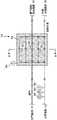
为了用太阳能热加热加热介质,使用把太阳能热收集到加热介质中的太阳能集热装置。太阳能集热装置中存在有抛物槽式集热器、菲涅尔式集热器(或线性菲涅尔集热器)、塔式集热器(或中央塔集热器)等等(参见专利文献2和3)。如图12中所示,抛物槽式集热器具有各自截面为抛物线形状的抛物槽镜1010。抛物槽镜1010被构造成朝向设置在抛物线的焦点、并且加热介质在其中流动的吸热管1012反射太阳光。抛物槽镜1010的倾角根据太阳的移动进行调整。In order to heat the heating medium with solar heat, a solar collector that collects solar heat into the heating medium is used. There are parabolic trough collectors, Fresnel collectors (or linear Fresnel collectors), tower collectors (or central tower collectors), etc. in solar collectors (see patent References 2 and 3). As shown in Fig. 12, the parabolic trough collector has
如图13中所示,菲涅尔式集热器具有多个平面镜1022。吸热管与平面镜1022平行地设置在平面镜1022的上方。平面镜被构造成根据太阳的移动,朝向吸热管1020反射太阳光。各平面镜1022的倾角根据太阳的移动进行调整。As shown in FIG. 13 , the Fresnel collector has a plurality of flat mirrors 1022 . The heat absorption pipe is arranged above the plane mirror 1022 parallel to the plane mirror 1022 . The plane mirror is configured to reflect sunlight toward the heat absorbing tube 1020 according to the movement of the sun. The inclination angle of each plane mirror 1022 is adjusted according to the movement of the sun.
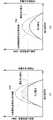
如图14A-14B中所示,塔式集热器具有包括加热介质在其中流动的顶部1030的塔1032,以及设置在各自以塔1032为中心并且至塔1032距离不同的多个同心圆、同心半圆或同心多边形上的多个平面镜1034(以下称为定日镜)。各定日镜1034被构造成朝向塔1032的顶部1030反射太阳光。各定日镜1034的倾角根据太阳的移动进行调整。As shown in FIGS. 14A-14B , the tower heat collector has a tower 1032 including a top 1030 in which a heating medium flows, and a plurality of concentric circles, concentric circles, concentric rings, etc. A plurality of plane mirrors 1034 (hereinafter referred to as heliostats) on a semicircle or concentric polygon. Each heliostat 1034 is configured to reflect sunlight toward the top 1030 of the tower 1032 . The inclination of each heliostat 1034 is adjusted according to the movement of the sun.
使用真空式管或非真空式管,作为用反射的太阳光照射(即,由太阳能热加热)的吸热管。抗散热并且热损失小的真空式管,例如由加热介质流过的钢管和围绕钢管的玻璃管构成。钢管与玻璃管之间的空间(即,腔室)保持真空状态。在钢管的外表面上,形成能够有选择地吸收特定波长的太阳光的涂膜。真空式管常常用在使用油作为加热介质并且使用抛物槽式集热器作为集热装置的系统中。Evacuated or non-evacuated tubes are used as heat absorbing tubes irradiated with reflected sunlight (ie, heated by solar heat). Evacuated tubes that are resistant to heat dissipation and have low heat loss, for example, consist of a steel tube through which a heating medium flows and a glass tube surrounding the steel tube. The space between the steel tube and the glass tube (ie, the chamber) is kept in a vacuum state. On the outer surface of the steel pipe, a coating film capable of selectively absorbing sunlight of a specific wavelength is formed. Evacuated tubes are often used in systems that use oil as the heating medium and parabolic trough collectors as the heat collector.
非真空式管例如是简单的钢管。非真空式管比真空式管更散热,但是具有实现低制造成本和容易处理的简单结构的优点。非真空式管常常用在使用水作为加热介质并且使用菲涅尔式集热器作为集热装置的系统中。Non-evacuated tubes are, for example, simple steel tubes. The non-evacuated type tube dissipates more heat than the vacuum type tube, but has the advantage of a simple structure enabling low manufacturing cost and easy handling. Non-evacuated tubes are often used in systems that use water as the heating medium and Fresnel collectors as the heat collector.
在专利文献4中,公开了一种加热介质流过其中并且蓄存加热介质的热量的管道。专利文献4中公开的太阳能热发电系统被构造成把加热介质的热量蓄存在管道中设置的蓄热介质中,并且用蓄存在蓄热介质中的热量加热加热介质。为了有选择地进行加热介质与蓄热介质之间的热交换,设置有与蓄热介质热连接的主供给管、与蓄热介质热隔离的旁通管、以及用于使加热介质流动至主供给管或旁通管中的任一者的控制阀。In Patent Document 4, a pipe through which a heating medium flows and stores heat of the heating medium is disclosed. The solar thermal power generation system disclosed in Patent Document 4 is configured to store heat of a heating medium in a heat storage medium provided in a pipe, and to heat the heating medium with the heat stored in the heat storage medium. In order to selectively exchange heat between the heating medium and the heat storage medium, a main supply pipe thermally connected to the heat storage medium, a bypass pipe thermally isolated from the heat storage medium, and a main supply pipe for allowing the heating medium to flow to the main A control valve for either the supply pipe or the bypass pipe.
引文列表Citation list
专利文献patent documents
专利文献1:日本特开2007-132330号公报Patent Document 1: Japanese Patent Laid-Open No. 2007-132330
专利文献2:日本特开2010-058058号公报Patent Document 2: Japanese Patent Laid-Open No. 2010-058058
专利文献3:日本特开2009-197733号公报Patent Document 3: Japanese Patent Laid-Open No. 2009-197733
专利文献2:WO2010/052710Patent Document 2: WO2010/052710
发明内容Contents of the invention
发明要解决的技术问题The technical problem to be solved by the invention
到达地面的太阳热能的强度(将称为直接日射辐照度或简称为DNI)根据季节、时间、天气、场所等变化。例如,美国丹佛的直接日射辐照度的变化如图15A-15C中所示,日照时间随日历日而不同,每天的直接日射辐照度随每天的时间而不同。直接日射辐照度随云遮蔽太阳等天气突变而急剧变化。即,存在太阳能热不能充分加热加热介质的可能性。因而,存在利用由太阳能热充分加热的气相加热介质(例如水蒸气)发电的太阳能热发电系统不能充分发电的可能性。The intensity of solar thermal energy reaching the ground (which will be called direct insolation irradiance or simply DNI) varies according to season, time, weather, location, etc. For example, the variation of direct solar irradiance in Denver, USA is shown in FIGS. 15A-15C , with sunshine hours varying with calendar days, and daily direct solar irradiance varying with time of day. Direct solar irradiance changes dramatically with sudden changes in weather such as clouds covering the sun. That is, there is a possibility that the solar heat cannot sufficiently heat the heating medium. Therefore, there is a possibility that a solar thermal power generation system that generates electricity using a gas-phase heating medium (such as water vapor) sufficiently heated by solar heat cannot generate electricity sufficiently.
作为应对该问题的一种措施,如专利文献4中公开的太阳能热发电系统中所述,可设想把由太阳能热充分或过度加热之后加热介质保持的一部分热量蓄存在蓄热介质中,并且利用蓄存在蓄热介质中的热量加热由太阳能热未充分加热的加热介质。为了能够在任何时候加热加热介质,需要提供用于蓄存大量热量的大量蓄热介质,以及用于容纳所述大量蓄热介质的大型容器设施(例如蓄热槽)。结果,这导致太阳能热发电系统的制造成本和维护成本的增加。As a measure to deal with this problem, as described in the solar thermal power generation system disclosed in Patent Document 4, it is conceivable to store a part of the heat retained by the heating medium after being sufficiently or excessively heated by solar heat in the thermal storage medium, and utilize The heat stored in the thermal storage medium heats the heating medium that was not sufficiently heated by the solar heat. In order to be able to heat the heating medium at any time, it is necessary to provide a large amount of heat storage medium for storing a large amount of heat, and a large container facility (such as a heat storage tank) for accommodating the large amount of heat storage medium. As a result, this leads to an increase in manufacturing cost and maintenance cost of the solar thermal power generation system.
作为应对该问题的另一种措施,可设想使用收集太阳能热的效率较高(即,加热介质的加热效率更高)的抛物槽式集热器或塔式集热器,而非菲涅尔式集热器。然而,与菲涅尔式集热器相比,抛物槽式集热器和塔式集热器需要更高的制造成本和更高的维护成本。As an alternative to this problem, it is conceivable to use parabolic trough collectors or tower collectors which are more efficient at collecting solar heat (i.e. more efficient heating of the heating medium) instead of Fresnel type collector. However, parabolic trough and tower collectors require higher manufacturing costs and higher maintenance costs than Fresnel collectors.
本发明的目的是提供一种具有廉价的结构,并且即使在诸如日照时间短、直接日射辐照度低、和/或直接日射辐照度急剧变化等情况下,也能够充分加热加热介质,从而能够充分发电的太阳能热发电系统。It is an object of the present invention to provide a structure that is inexpensive and capable of sufficiently heating the heating medium even under conditions such as short periods of sunlight, low direct solar irradiance, and/or sharp changes in direct solar irradiance, thereby A solar thermal power generation system capable of generating sufficient electricity.
解决问题的手段means of solving problems
为了实现该目的,本发明如下构成。In order to achieve this object, the present invention is constituted as follows.
根据本发明的一方面,提供了一种使用在液相与气相之间进行相变的加热介质的太阳能热发电系统,所述太阳能热发电系统包括:由太阳能热加热加热介质的菲涅尔式集热器;在排出废气的同时发电的燃气轮机发电装置;加热装置,包括由菲涅尔式集热器加热后的加热介质流过的第一通道,和位于第一通道附近并且来自燃气轮机发电装置的废气流过的第二通道,所述加热装置用于由第二通道中的废气加热第一通道中的加热介质;把由加热装置加热后的加热介质分离成气相和液相的气液分离装置;以及由气液分离装置分离的气相的加热介质驱动的涡轮发电装置。According to an aspect of the present invention, there is provided a solar thermal power generation system using a heating medium that undergoes a phase change between a liquid phase and a gas phase, the solar thermal power generation system comprising: a Fresnel type heating medium heated by solar heat A heat collector; a gas turbine power generation device that generates electricity while exhausting exhaust gas; a heating device including a first passage through which a heating medium heated by a Fresnel type heat collector flows, and a gas turbine power generation device located near the first passage and from the gas turbine power generation device The exhaust gas flows through the second channel, and the heating device is used to heat the heating medium in the first channel by the exhaust gas in the second channel; the heating medium heated by the heating device is separated into a gas phase and a liquid phase for gas-liquid separation device; and a turbine power generation device driven by a heating medium of the gas phase separated by the gas-liquid separation device.
发明的效果The effect of the invention
根据本发明,使用廉价的结构,即使在诸如日照时间短、直接日射辐照度低、和/或直接日射辐照度急剧变化等情况下,也能够充分加热加热介质,因而太阳能热发电系统能够充分发电。According to the present invention, using an inexpensive structure, the heating medium can be sufficiently heated even under conditions such as short sunshine hours, low direct solar irradiance, and/or sharp changes in direct solar irradiance, so that the solar thermal power generation system can Full power generation.
附图说明Description of drawings
根据参照附图关于优选实施例的说明,本发明的不同方面和特征将是显而易见的,在附图中:Various aspects and features of the invention will be apparent from the description of preferred embodiments with reference to the accompanying drawings, in which:
图1是根据本发明的实施例1的集成太阳能联合循环发电厂的概念图;1 is a conceptual diagram of an integrated solar combined cycle power plant according to Embodiment 1 of the present invention;
图2是图1中所示的集成太阳能联合循环发电厂的示意性结构图;Fig. 2 is a schematic structural diagram of the integrated solar combined cycle power plant shown in Fig. 1;
图3是加热装置的示意性结构图;Fig. 3 is a schematic structural diagram of a heating device;
图4是图3中所示的加热装置的截面图;Figure 4 is a cross-sectional view of the heating device shown in Figure 3;
图5A-5B是示出直接日射辐照度(DNI)与汽轮机的电力输出之间的关系的图;5A-5B are graphs illustrating the relationship between direct insolation irradiance (DNI) and the electrical output of a steam turbine;
图6是比较例的加热装置的示意性结构图;Fig. 6 is a schematic structural diagram of a heating device of a comparative example;
图7是实施例1的改进形式的加热装置的截面图;Fig. 7 is the sectional view of the heating device of the modified form of embodiment 1;
图8是比较例的集成太阳能联合循环发电厂的示意性结构图;Fig. 8 is a schematic structural diagram of an integrated solar combined cycle power plant of a comparative example;
图9是根据本发明的实施例2的集成太阳能联合循环发电厂中的加热装置的示意性结构图;Fig. 9 is a schematic structural diagram of a heating device in an integrated solar combined cycle power plant according to Embodiment 2 of the present invention;
图10是根据本发明的实施例3的集成太阳能联合循环发电厂中的加热装置的示意性结构图;Fig. 10 is a schematic structural diagram of a heating device in an integrated solar combined cycle power plant according to Embodiment 3 of the present invention;
图11是根据本发明的实施例4的集成太阳能联合循环发电厂中的加热装置的示意性结构图;11 is a schematic structural diagram of a heating device in an integrated solar combined cycle power plant according to Embodiment 4 of the present invention;
图12是示出抛物槽式集热器的图;Figure 12 is a diagram showing a parabolic trough collector;
图13是示出菲涅尔式集热器的图;Figure 13 is a diagram showing a Fresnel collector;
图14A-14B是示出塔式集热器的图;并且14A-14B are diagrams showing tower collectors; and
图15A-15C是示出根据日历日和根据每天的时间而不同的直接日射辐照度的变化的图。15A-15C are graphs showing changes in direct solar irradiance according to calendar days and according to time of day.
具体实施方式Detailed ways
以下,将参照附图说明本发明的实施例。Hereinafter, embodiments of the present invention will be described with reference to the drawings.
(实施例1)(Example 1)
图1概念性地示出根据本发明的实施例1的太阳能热发电系统(即,集成太阳能联合循环发电厂)的结构。FIG. 1 conceptually shows the structure of a solar thermal power generation system (ie, an integrated solar combined cycle power plant) according to Embodiment 1 of the present invention.
图1中所示的集成太阳能联合循环(简称为ISCC)发电厂10是通过利用太阳能热和加热介质发电的太阳能热发电系统的一个示例,并且包括多个发电源。An integrated solar combined cycle (abbreviated as ISCC)
这里,“加热介质”是指能够在保持热量的同时流动的流体。在本实施例中,使用廉价的水作为在液相与气相之间进行相变的加热介质。Here, "heating medium" refers to a fluid that can flow while maintaining heat. In this embodiment, inexpensive water is used as a heating medium for phase transition between liquid phase and gas phase.
如图1所示,集成太阳能联合循环发电厂10具有利用太阳能热使液相的加热介质(即,水)蒸发(即,产生蒸汽)的太阳能场12,加热由太阳能热加热后的、气相的比例低的加热介质以便提高气相的比例的加热装置14,利用由加热装置14加热后的气相的加热介质驱动的汽轮机发电装置18,以及在向加热装置14供给热废气的同时发电的燃气轮机发电装置20。As shown in Figure 1, an integrated solar combined
太阳能场12、加热装置14和燃气轮机发电装置20构成向汽轮机发电装置18供给气相的加热介质的加热介质供给装置。利用汽轮机发电装置18和燃气轮机发电装置20两者发电,利用从燃气轮机发电装置20排出的废气加热和蒸发液相的加热介质,并利用气相的加热介质驱动汽轮机发电的系统被称为燃气轮机联合循环发电厂(即,ccpp)。The
图2示出集成太阳能联合循环发电厂10的具体结构。将根据加热介质的逐步说明,说明集成太阳能联合循环发电厂10的多个组成元件。附图仅示出与本发明相关的主要组成元件。存在未示出的其它组成元件。必须注意的是,以下说明的多个组成元件与本发明相关,但并不是集成太阳能联合循环发电厂10所需的全部组成元件。FIG. 2 shows the specific structure of the integrated solar combined
太阳能场12包括利用太阳能热加热液相的加热介质的菲涅尔式集热器22。菲涅尔式集热器22具有用于加热在吸热管24中流动的液相加热介质的多个平面镜22a。平面镜22a被配置成反射太阳光并用反射的太阳光照射吸热管24。平面镜22a的倾角根据太阳的移动进行调整。The
本发明的吸热管24可以是真空式管或非真空式管。真空式管具有更高的集热效率,但是制造成本更高。非真空式管比真空式管集热效率低,但是因为廉价所以在设备成本方面更有利。The
采用菲涅尔式集热器22作为用于由太阳能热加热加热介质的集热装置,是因为菲涅尔式集热器使用结构简单并且成本低廉的多个平面镜22a,所以比其它集热装置更便宜。Adopting the Fresnel
作为其它的集热装置,图12中所示的抛物槽式集热器具有比菲涅尔式集热器22更高的集热效率,并且常用于具有30MW或更大的大功率输出的太阳能热发电系统。由于通常使用油作为加热介质,因此使用温度有限制(例如约400℃,尽管取决于油的种类)。抛物槽式集热器的制造成本比菲涅尔式集热器高。As other heat collectors, the parabolic trough collector shown in Fig. 12 has higher heat collection efficiency than the
图14中所示的塔式集热器也具有比菲涅尔式集热器22高的集热效率。在使用熔盐作为加热介质的系统中,加热介质可被加热至极高的温度(例如,在使用硝酸钾和硝酸钠的混合盐的情况下超过约560℃的温度,尽管取决于熔盐的种类)。塔式集热器1032需要抗震强度,和把加热介质送到塔1032的顶部1030的高输出泵(未示出)。因而,制造成本比菲涅尔式集热器高。The tower collector shown in FIG. 14 also has a higher heat collection efficiency than the
菲涅尔式集热器22与其它集热装置相比,能够以较低成本构成,但是与其它集热装置相比,集热效率较低。为了提高菲涅尔式集热器22的集热效率,在集成太阳能联合循环发电厂10中设置加热装置14。The
如图1和图2中所示,由于太阳能场12的加热而蒸发的气相加热介质从吸热管24流出,并通过加热装置14。加热装置14加热加热介质,并提高气相加热介质的比例,使得能够向汽轮机发电装置18供给额定的蒸汽流量。优选地,在被加热装置14加热之后,加热介质全部变成气相。加热装置14的细节将在后面说明。As shown in FIGS. 1 and 2 , the vaporized heating medium due to the heating of the
由加热装置14加热后的加热介质由气液分离装置26分离成气相(即,蒸汽)和液相(即,水)。液相加热介质返回至太阳能场12。气相加热介质被供给并储存在储气罐(即,缓冲罐)28中。在储存于储气罐28期间相变为液相的加热介质返回至太阳能场12。The heating medium heated by the
储存在储气罐28中的气相加热介质随后由流量控制阀30控制,以便达到汽轮机发电装置18的额定蒸汽流量。加热介质被提供给汽轮机发电装置18。加热介质(即,蒸汽)驱动汽轮机发电装置18的汽轮机18a。汽轮机18a驱动发电机18b。发电机18b发电。The gas-phase heating medium stored in the
在驱动汽轮机18a之后,气相加热介质由冷凝器32液化。液化的加热介质由泵34输送,由给水加热器36加热,并且由脱气器38脱气。脱气后的加热介质由泵42输送至太阳能场12。After the
下面,将说明加热装置14的细节。图3示意性地示出加热装置14的结构。图4示出加热装置14的截面(A-A截面)。Next, details of the
以下将说明加热装置14的作用。如上所述,需要额定量的蒸汽(即,气相加热介质),以便汽轮机发电装置18能够产生额定的电力。图5A-5B示出一天中的太阳热能强度(DNI)(由点划线表示),汽轮机发电装置18的发电量(由实线表示),和太阳能场12获得的太阳热能(由双点划线表示)。如图5B中所示,在太阳能场12中获得的太阳热能并不与从该热能转换的发电量完全一致。原因在于在太阳热能转换成电能的过程中,因汽轮机发电装置18中的铜损、铁损、滑动摩擦等导致能量损失。The function of the
对太阳能热发电系统的计划而言,通常,基于建造太阳能场12的场所的平均直接日射辐照度,确定汽轮机发电装置18的额定电力输出。原因在于,一天中仅短时间内能够获得最大直接日射辐照度,而在几乎所有其它时间内汽轮机发电装置必须以部分负荷运转。由于以部分负荷运转时汽轮机的效率降低,因而整个发电系统的发电效率降低。因此,基于“平均直接日射辐照度”而非最大直接日射辐照度,确定汽轮机发电装置18的额定电力输出是合理的。“平均直接日射辐照度”是指在假定通过用假想的恒定直接日射辐照度进行计算,获得与利用一天中变化的实际直接日射辐照度所获得的发电量相等的发电量的情况下,得到的假想的恒定直接日射辐照度。在计划的具体步骤中,作为第一步,计算利用根据平均直接日射辐照度提供的太阳能热,在太阳能场12中产生的气相加热介质(即,蒸汽)的量。作为第二步,根据计算的气相加热介质的量,计算可能的发电量。基于计算的发电量,确定汽轮机发电装置18的规格。For planning of a solar thermal power system, typically, the rated electrical output of the
图5A示出一天内的直接日射辐照度有几小时超过平均直接日射辐照度的日子。图5B示出一天内的直接日射辐照度低于平均直接日射辐照度的日子。Figure 5A shows days during which the direct solar irradiance exceeds the average direct solar irradiance for several hours. FIG. 5B shows days in which the direct solar irradiance is lower than the average direct solar irradiance within a day.
在如图5A中所示的直接日射辐照度超过平均直接日射辐照度的情况下,从太阳能场12输出的加热介质具有较大的气相比例。因而,能够获得额定或更大的蒸汽流量。尽管能够产生额定或更大的电力输出,然而汽轮机发电装置18以电力输出不超过额定电力输出的方式运转。即,发生太阳热能的阴影部分未被有效利用的状况。In cases where direct solar irradiance exceeds average direct solar irradiance as shown in FIG. 5A , the heating medium output from
在如图5B中所示的一天中的直接日射辐照度低于平均直接日射辐照度的情况下,从太阳能场12输出的加热介质具有较小的气相比例。即,不能获得额定蒸汽流量。因此,发生汽轮机发电装置18的电力输出未达到额定电力输出的状况。In the case of a day in which direct solar irradiance is lower than average direct solar irradiance as shown in FIG. 5B , the heating medium output from the
考虑到这些事实,加热装置14被配置成利用来自燃气轮机发电装置20的废气,加热由太阳能热(即,由太阳能场12)加热后的加热介质。结果,汽轮机发电装置18能够稳定地产生额定电力,而不废弃太阳热能。设置加热装置14,以便辅助集热效率低于其它集热装置的菲涅尔式集热器22。Taking these facts into account, the
如图3和图4中所示,加热装置14具有加热介质从太阳能场12向气液分离装置26流过的加热介质通道(即,第一通道)50,从燃气轮机发电装置20排出的热废气通过的废气通道(即,第二通道)52,以及能够储存热量的加热材料54。As shown in FIGS. 3 and 4 , the
加热介质通道50和废气通道52由能够在加热介质和废气流动的通道的内部空间与该空间的外部之间进行有效热交换的例如钢管制成。图4示出圆筒形的通道和通道的环形布置,然而通道的形状和布置并不局限于此。The
吸收并储存来自其它物体的热量并把储存的热量提供给其它物体的加热材料54是例如混凝土、沙子、熔盐和陶瓷粉末等材料,但不局限于此。加热材料54可以是密闭空气等的气体。The
如图4中所示,加热材料54与加热介质通道50或加热介质直接地热连接。加热材料54也与废气通道52或废气直接地热连接。因而,加热材料54能够从加热介质或废气吸收并储存热量,并且能够通过向加热介质供给热量,由储存的热量加热加热介质。即,废气和加热介质通过加热材料54相互间接地热连接。As shown in FIG. 4 , the
集成太阳能联合循环发电厂10被配置成使得能够基于从太阳能场12流入加热介质通道50中的气相加热介质的量,控制燃气轮机发电装置20的电力输出,并且调节供给至废气通道52中的废气的量。The integrated solar combined
设置流量测量装置58、压力测量装置60和温度测量装置62,以便测量流入加热介质通道50中的气相加热介质的量。基于由流量测量装置58测量的加热介质的流量,由压力测量装置60测量的加热介质的压力,以及由温度测量装置62测量的加热介质的温度,计算流入加热介质通道50中的气相加热介质的量。A
流入加热装置14中的加热介质通道50中的气相加热介质的量的计算,和基于计算结果对燃气轮机发电装置20的控制,由集成太阳能联合循环发电厂10的主计算机(未示出)进行。主计算机控制例如汽轮机发电装置18、燃气轮机发电装置20、冷凝器32、脱气器38、流量控制阀30、泵34、42等多种装置。Calculation of the amount of gas-phase heating medium flowing into the
加热装置14被配置成在从太阳能场12供给的气相加热介质的量大于规定量的情况下,由加热材料54吸收加热介质中保持的热量。加热装置14被配置成在气相加热介质的量小于规定量的情况下,由加热材料54中储存的热量加热加热介质。这里,气相加热介质的“规定量”是基于在到达汽轮机发电装置18之前损失的量和额定量计算的量。The
在本实施例中,通过控制燃气轮机发电装置20的电力输出,调节供给至废气通道52中的废气的量,使得加热材料54的温度可在规定温度(即,与规定量的储存热量对应的温度)下保持恒定。规定温度优选地设定成使得在流经加热介质通道50的气相加热介质的量与规定量几乎一样大的情况下,不从加热介质向加热材料54传热的温度。为此,在加热装置14中设置用于检测加热材料54的温度的温度测量装置64。温度测量装置64可设置在加热装置14中的任意位置,只要能够测量与加热材料54的温度(即,保持热量)相关的温度。In this embodiment, by controlling the power output of the gas turbine
在加热材料54保持在规定的恒定温度时,流经加热介质通道50的气相加热介质的量超过规定量的情况下,通过降低或中断燃气轮机发电装置20的发电,减少供给至废气通道52中的废气的量。结果,加热材料54中的保持热量减少,使得加热介质中的保持热量的一部分可被加热材料54吸收。在气相加热介质的量低于规定量的情况下,通过增大或重启燃气轮机发电装置20的发电,增加废气的供给量。结果,加热材料54中的保持热量增加,使得加热材料54中的保持热量的一部分可供给至加热介质。因而,从加热装置14输出的气相加热介质的量可维持在规定量。When the
当开始集成太阳能联合循环发电厂10的运转时,为增加加热材料54中的保持热量的目的,或者为使加热介质通道50和废气通道52变暖的目的(即,为使加热装置14变暖的目的),可通过控制燃气轮机发电装置20,把废气供给至废气通道52中。When starting the operation of the integrated solar combined
以下,将说明加热装置14的优点。Hereinafter, advantages of the
作为一个优点,通过加热装置14的补充加热,能够把气相加热介质充分、稳定地供给至汽轮机发电装置18。即,在日照时间短、直接日射辐照度低和/或直接日射辐照度急剧变化等情况下,加热装置14补充加热太阳能场12未充分加热的加热介质。结果,汽轮机发电装置18能够充分地发电。加热加热介质的热源是从燃气轮机发电装置20排出的废气,因而在产生废气时,燃气轮机发电装置20产生的电力可用作集成太阳能联合循环发电厂10的电力输出。由于这些效果,提高了太阳热能的可利用性。例如,即使在直接日射辐照度低的情况下,也不必停止集成太阳能联合循环发电厂10的运转。As an advantage, the gas-phase heating medium can be sufficiently and stably supplied to the steam turbine
作为另一个优点,能够减少加热材料54的量。为了具体说明这一优点,图6示出仅仅由加热材料而不利用废气加热从太阳能场供给的加热介质的加热装置的比较例。As another advantage, the amount of
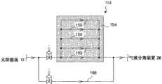
在图6中所示的比较例的加热装置114中,在加热材料154中的储存热量接近下限,并且从太阳能场12供给的气相加热介质的量与规定量几乎一样大的情况下,必须设置加热介质流过且与加热材料154无热连接的旁路通道166。In the
在图2和图3的实施例1的加热装置14中,利用废气使加热材料54的温度(即,保持热量)维持恒定,因而加热材料54不会大量地吸收加热介质的热量。In the
在比较例的加热装置114中,在加热材料154中的储存热量接近下限,并且从太阳能场12供给的气相加热介质的量低于规定量的情况下,不能由加热材料154中的储存热量加热加热介质。因而,汽轮机发电装置18的发电量降低。因此,需要大量的加热材料154。In the
在图2和图3的实施例1的加热装置14中,不仅因为利用燃气轮机发电装置20的废气,使加热材料54的温度(即,储存热量)维持恒定,而且因为通过增大燃气轮机发电装置20的发电,可增加供给至废气通道52中的废气的量,所以能够加热加热介质。In the
在比较例的加热装置114中,在加热材料154中的储存热量接近上限,并且从太阳能场12供给的气相加热介质的量超过规定量的情况下,加热材料154不能吸收加热介质的热量。比较例的加热装置114被配置成利用加热材料154中的储存热量加热加热介质,因而加热材料154与外部热隔离(即,加热材料154的自发散热受到抑制)。因此,需要大量的加热材料154。In the
在实施例1的加热装置14中,在加热材料54中的保持热量接近上限,并且从太阳能场12供给的气相加热介质的量超过规定量的情况下,通过停止燃气轮机发电装置20,停止向废气通道52的废气的供给。结果,通过减少加热材料54中的储存热量,加热介质的热量可被加热材料54吸收。即,废气供给的停止导致加热材料54中的储存热量的一部分转移到废气通道52中,并通过排气烟囱48扩散在空气中。In the
考虑到这些事实,在比较例的加热装置114中,需要旁路通道166和大量的加热材料154。此外,需要容纳大量的加热材料154的大型容器。这增加了制造成本。In consideration of these facts, in the
实施例1的加热装置14不需要大量的加热材料54,因而实现了较低的制造成本。The
本发明可包括用于避免加热介质与加热材料54之间的热交换的任何旁路通道。在频繁从太阳能场12供给规定量的气相加热介质的情况下,加热装置14优选地包括旁路通道。The present invention may include any bypass channels for avoiding heat exchange between the heating medium and the
如图7中所示,加热介质通道50(即,加热介质)和废气通道52(即,废气)可相互直接热连接,使得可由废气直接加热加热介质。这种结构使得与如图4中所示由废气通过加热材料54间接加热加热介质的结构相比,能够对直接日射辐照度的急剧变化(即,气相加热介质的量的急剧变化)作出更快响应。在例如因天气突变,流过加热介质通道50的气相加热介质的量急剧减小的情况下,通过增加燃气轮机发电装置20的电力输出,能够增加供给至废气通道52中的废气的量,使得能够用废气中的保持热量的一部分(即,转移到加热介质通道50中的热量),快速加热加热介质。As shown in FIG. 7 , the heating medium channel 50 (ie, the heating medium) and the exhaust gas channel 52 (ie, the exhaust gas) may be directly thermally connected to each other such that the heating medium may be directly heated by the exhaust gas. This structure makes it possible to respond more quickly to sharp changes in direct solar irradiance (that is, to sharp changes in the amount of heating medium in the gaseous phase) than the structure in which the heating medium is indirectly heated by the exhaust gas through the
如图3中所示,在加热介质流入加热介质通道50之前,即,在加热介质与加热材料54之间进行热交换之前,基于流量测量装置58、压力测量装置60和温度测量装置62等测量装置的测量结果,计算气相加热介质的量。在这种设置中,基于气相加热介质的量,对供给至废气通道52中的废气的量的调节(即,燃气轮机发电装置20的控制)进行前馈控制。替代性地,可在气相加热介质从加热介质通道50流出之后,即,在加热介质与加热材料54之间进行热交换之后,测量气相加热介质的量。在这种设置中,基于气相加热介质的量,对供给至废气通道52中的废气的量的调节(即,燃气轮机发电装置20的控制)进行反馈控制。可以组合进行前馈控制和反馈控制。结果,能够精确地调节废气的量。As shown in FIG. 3 , before the heating medium flows into the
为了调节供给至加热装置14的废气通道52中的废气的量(即,为了控制燃气轮机发电装置20),测量并计算气相加热介质的量,然而本发明并不局限于此。可基于液相加热介质的量的测量结果,调节供给至废气通道52中的废气的量。例如,如图2中所示,设置用于测量由气液分离装置26分离的液相加热介质的量的流量测量装置68,并且基于由流量测量装置68测量的液相加热介质的量,调节燃气轮机发电装置20的发电(即,供给至废气通道52中的废气的量)。例如,在由流量测量装置68测量的液相加热介质的量增加的情况下,燃气轮机发电装置20的电力输出增大,并且供给至废气通道52中的废气的量增加。在由流量测量装置68测量的液相加热介质的量减小的情况下,燃气轮机发电装置20的电力输出减小,并且供给至废气通道52中的废气的量减小。In order to adjust the amount of exhaust gas supplied to the
关于流量测量装置68,在由流量测量装置68测量的液相加热介质的量与由太阳能场12加热之前的液相加热介质的量(即,泵42供给至太阳能场12的加热介质的量)几乎一样大的情况下,可通过停止燃气轮机发电装置20,停止向加热装置14中的废气通道52的废气的供给。由流量测量装置68测量的液相加热介质的量与由太阳能场12加热之前的液相加热介质的量几乎一样大是有原因的。原因在于由于直接日射辐照度低,即使在利用加热装置14加热加热介质之后,气相加热介质的量也不能增加。Regarding the
可基于由流量测量装置68测量的液相加热介质的量,调节供给至太阳能场12的液相加热介质的量(即,泵42供给至太阳能场12的加热介质的量)。例如,在由流量测量装置68测量的液相加热介质的量增加的情况下,通过泵42供给至太阳能场12的液相加热介质的量减少。在由流量测量装置68测量的液相加热介质的量减少的情况下,通过泵42供给至太阳能场12的液相加热介质的量增加。因而,加热装置14能够充分发挥其加热能力。即,可抑制向加热装置14供给超过加热装置14的加热能力(即,蒸发液相加热介质的能力)的大量的液相加热介质。而是向加热装置14供给能够充分利用加热装置14的最佳量的液相加热介质。The amount of heating medium in liquid phase supplied to solar field 12 (ie, the amount of heating medium supplied to
关于泵42,优选地在太阳能场12的吸热管24的温度变得足够高时,泵42开始向太阳能场12供给液相加热介质。在吸热管24的温度未高到足以使加热介质从液相相变成气相的情况下,大量的液相加热介质将不变成气相地从吸热管24流动到加热装置14,因而加热装置14将被冷却。结果,加热装置14的加热材料54储存的热量将被带走。Regarding the
因此,控制泵42使得当太阳能热(即,来自镜22a的反射光)把吸热管24加热到足够热时,开始向太阳能场12供给液相加热介质。例如,当在吸热管24中测量的温度与在加热装置14中测量的温度几乎相等时,泵42开始向太阳能场12供给液相加热介质。这抑制由于供给大量的液相加热介质而使加热装置14冷却。Accordingly, the
如图2中所示,在燃气轮机发电装置20与加热装置14之间,可设置把废气通过排气烟囱48排放到空气中的溢流阀44。例如,存在在汽轮机发电装置18产生额定电力的同时,另外需要燃气轮机发电装置20产生的电力的情况。当汽轮机发电装置18产生额定电力时,从燃气轮机发电装置20向加热装置14的废气的供给将导致已被太阳能场12充分加热的加热介质的过热。为了避免这种情况,可设置溢流阀44,以便调节从燃气轮机发电装置20供给至加热装置14的废气的量。因而,集成太阳能联合循环发电厂10能够输出汽轮机发电装置18产生的额定电力与燃气轮机发电装置20产生的另一额定电力之和。As shown in FIG. 2 , between the gas turbine
以下,将与类似比较例的集成太阳能联合循环发电厂相比较地说明实施例1的集成太阳能联合循环发电厂10的优点。图8示出比较例的集成太阳能联合循环发电厂10'的结构。Hereinafter, the advantages of the integrated solar combined
除加热装置14之外,图8中所示的比较例的集成太阳能联合循环发电厂10'具有与图2中所示的实施例1的集成太阳能联合循环发电厂10基本相同的组成元件。替代加热装置14,比较例的集成太阳能联合循环发电厂10'具有实施例1的集成太阳能联合循环发电厂10不具有的废热回收锅炉装置16。The integrated solar combined
废热回收锅炉装置16包括节能器(预热器)16a、蒸发器16b和过热器16c,并配置成使用来自燃气轮机发电装置20的废气,加热(即,过热)由气液分离装置26分离的气相加热介质。The waste heat
具体地,从储气罐28供给至废热回收锅炉装置16的加热介质与由蒸发器16b蒸发的加热介质混合,随后流入过热器16c。由过热器16c过热的加热介质(即,过热蒸气)被供给至汽轮机18a。Specifically, the heating medium supplied from the
由脱气器38脱气的一部分加热介质由泵40输送至废热回收锅炉装置16,由节能器(即,预热器)16a预热,由蒸发器16b蒸发,并与从储气罐28供给的加热介质混合。A part of the heating medium degassed by the
作为使液相加热介质预热、蒸发和过热的热源,从燃气轮机发电装置20的燃气轮机20a排出的废气被供给至废热回收锅炉装置16。Exhaust gas discharged from the
从燃气轮机发电装置20供给至废热回收锅炉装置16的废气最终通过排气烟囱46排放在空气中。The exhaust gas supplied from the gas turbine
图8中所示的比较例的集成太阳能联合循环发电厂10'因为具有这种废热回收锅炉装置16,所以与实施例1的集成太阳能联合循环发电厂10相比,增加了制造成本。Compared with the integrated solar combined
因为需要向废热回收锅炉装置16持续供给废气,所以在集成太阳能联合循环发电厂10'运行时,比较例的燃气轮机发电装置20需要连续运转。即,在停止从燃气轮机发电装置20向废热回收锅炉装置16供给废气的情况下,从气液分离装置26供给的气相加热介质将被从脱气器38供给的液相加热介质冷却。因此,这使得不能向汽轮机发电装置18供给足够量的气相加热介质,并导致汽轮机发电装置18的发电停止。因此,比较例的燃气轮机发电装置20需要连续运转。Since exhaust gas needs to be continuously supplied to the waste heat
在比较例的集成太阳能联合循环发电厂10'中,在太阳能场12与气液分离装置26之间未设置如实施例1中的加热加热介质的加热装置14。因此,为了从太阳能场12通过气液分离装置26向汽轮机发电装置18稳定地供给气相加热介质,除了应用集热效率更高的集热装置,例如昂贵的抛物槽式集热器或昂贵的塔式集热器之外,别无选择。In the integrated solar combined
比较例的集成太阳能联合循环发电厂10'不具有加热装置14,而是包括废热回收锅炉装置16和集热效率更高的昂贵的集热装置,因而与实施例1的集成太阳能联合循环发电厂10相比,增加了制造成本。The integrated solar combined cycle power plant 10' of the comparative example does not have a
尽管包括集热效率更高的抛物槽式集热器,然而比较例的集成太阳能联合循环发电厂10'在日照时间短、直接日射辐照度低和/或直接日射辐照度急剧变化等情况下,不能向汽轮机发电装置18供给足够量的气相加热介质。另一方面,实施例1的集成太阳能联合循环发电厂10包括加热装置14,即使在日照时间短、直接日射辐照度低和/或直接日射辐照度急剧变化等情况下,也能够向汽轮机发电装置18供给足够量的气相加热介质。Although it includes a parabolic trough collector with higher heat collection efficiency, the integrated solar combined cycle power plant 10' of the comparative example suffers from short sunshine hours, low direct solar irradiance, and/or sharp changes in direct solar irradiance. , a sufficient amount of gas-phase heating medium cannot be supplied to the
在实施例1中,即使在日照时间短、直接日射辐照度低和/或直接日射辐照度急剧变化等情况下,也能够利用廉价的结构充分加热加热介质。此外,加热介质能够被充分蒸发,因此能够向汽轮机发电装置18供给足够量的气相加热介质。结果,汽轮机发电装置18(即,集成太阳能联合循环发电厂10)能够产生足够的电力。In Example 1, the heating medium can be sufficiently heated with an inexpensive structure even in the case of short sunlight time, low direct solar irradiance, and/or sudden change in direct solar irradiance. In addition, the heating medium can be sufficiently vaporized, so that a sufficient amount of the heating medium in the gas phase can be supplied to the steam turbine
(实施例2)(Example 2)
除加热装置之外,根据实施例2的集成太阳能联合循环发电厂与实施例1相同。以下,将说明根据实施例2的加热装置。The integrated solar combined cycle power plant according to Example 2 is the same as Example 1 except for the heating device. Hereinafter, a heating device according to Embodiment 2 will be described.
图9示出实施例2的加热装置214。不同于实施例1的加热装置14,实施例2的加热装置214不具有加热材料。加热介质通道250(即,加热介质)与废气通道252(即,废气)相互热连接。FIG. 9 shows the
在实施例2的加热装置214中,在从太阳能场12供给的气相加热介质的量(即,基于流量测量装置258、压力测量装置260和温度测量装置262的测量结果计算的气相加热介质的量)超过规定量的情况下,通过降低燃气轮机发电装置20的电力输出,减少供给至废气通道252中的废气的量,或者通过停止发电而停止废气的供给。在加热介质流经加热介质通道250的同时,其中的一部分保持热量进入废气通道252,并通过排气烟囱48扩散到空气中。In the
在从太阳能场12供给的气相加热介质的量低于规定量的情况下,基于气相加热介质的量,通过提高燃气轮机发电装置20的电力输出,增加供给至废气通道252中的废气的量,或者通过恢复燃气轮机发电装置20的发电,恢复废气的供给。In the case where the amount of the gas-phase heating medium supplied from the
实施例2的加热装置214不具有加热材料,因此与实施例1的加热装置14相比更紧凑。由于不具有加热材料,因此加热装置214既不能吸收也不能保持加热介质中的储存热量。因此,在从太阳能场12供给的气相加热介质的量超过规定量的情况下,不能由加热材料吸收和储存加热介质中的一部分保持热量。并且,不能利用加热材料中的储存热量加热加热介质。The
在频繁从太阳能场12供给规定量的气相加热介质的情况下,加热装置214优选地包括与废气通道252热隔离的旁路通道。In the case of frequent supply of defined quantities of heating medium in gaseous phase from the
(实施例3)(Example 3)
除加热装置之外,根据实施例3的集成太阳能联合循环发电厂与实施例1相同。以下,将说明根据实施例3的加热装置。The integrated solar combined cycle power plant according to Example 3 is the same as Example 1 except for the heating device. Hereinafter, a heating device according to Embodiment 3 will be described.
图10示出实施例3的加热装置314。在实施例3的加热装置314中,不同于实施例1的加热装置14,加热材料354与废气通道352(即,废气)相互热隔离。即,在加热材料354与废气之间不换热。FIG. 10 shows the
因此,加热装置314具有仅与废气通道352热连接的加热介质通道350a,仅与加热材料354热连接的加热介质通道350b,和用于向至少加热介质通道350a或加热介质通道350b供给加热介质的流量控制阀356a、356b。Therefore, the
对实施例3的加热装置314而言,基于从太阳能场12供给的气相加热介质的量,控制燃气轮机发电装置20。基于流量测量装置358、压力测量装置360和温度测量装置362的测量结果,以及温度测量装置368的测量结果(即,加热材料354中的储存热量),计算加热介质的量。结果,调节供给至废气通道352中的废气的量,并且控制流量控制阀356a、356b。In the
在从太阳能场12供给的气相加热介质的量低于规定量的情况下,一部分加热介质被供给至加热介质通道350a中,以便由废气加热,而另一部分加热介质被供给至加热介质通道350b中,以便由加热材料354加热。In the case where the amount of the gas-phase heating medium supplied from the
具有这种结构的加热装置314能够精确地控制供给至气液分离装置26的气相加热介质的量。The
在频繁从太阳能场12供给规定量的气相加热介质的情况下,加热装置314优选地包括与废气通道352和加热材料354热隔离的旁路通道。In the case of frequent supply of a prescribed amount of heating medium in gaseous phase from the
(实施例4)(Example 4)
除加热装置之外,实施例4的集成太阳能联合循环发电厂与实施例1相同。以下,将说明根据实施例4的加热装置。The integrated solar combined cycle power plant of Embodiment 4 is the same as Embodiment 1 except for the heating device. Hereinafter, a heating device according to Embodiment 4 will be described.
图11示出实施例4的加热装置414。在实施例4的加热装置414中,不同于实施例1的加热装置14,加热材料454与废气通道452(即,废气)相互热隔离。在加热材料454与废气之间不换热。FIG. 11 shows the
加热装置414具有仅与废气通道452热连接的加热介质通道450a,和仅与加热材料454热连接的加热介质通道450b。加热装置414被配置成使得通过加热介质通道450b的加热介质必然流过加热介质通道450a(即,在这点上,加热装置414与实施例3不同)。The
在实施例4的加热装置414中,通过基于从太阳能场12供给的气相加热介质的量,控制燃气轮机发电装置20,来调节供给至废气通道452中的废气的量。基于流量测量装置458、压力测量装置460和温度测量装置462的测量结果,以及温度测量装置468的测量结果(即,加热材料454中的储存热量),计算气相加热介质的量,In the
在从太阳能场12供给的气相加热介质的量低于规定量的情况下,加热介质在通过加热介质通道450b的同时被加热材料454加热,随后加热介质在通过加热介质通道450a的同时,被流过废气通道452的废气加热。In the case where the amount of the gas-phase heating medium supplied from the
具有这种结构的加热装置414能够精确地控制供给至气液分离装置26的气相加热介质的量。实施例4的加热装置414的结构比实施例3的加热装置314简单。The
在频繁从太阳能场12供给规定量的气相加热介质的情况下,加热装置414优选地包括与废气通道452热隔离的旁路通道,以及与加热材料454热隔离的旁路通道。In the case of frequent supply of a prescribed amount of heating medium in gaseous phase from the
尽管已参照附图,结合优选实施例,充分说明了本发明,然而应当注意的是,对本领域技术人员而言,多种变型和改型是明显可见的。这样的变型和改型应被理解为包含在由所附权利要求限定的本发明的范围内,除非其脱离该范围。Although the invention has been fully described in conjunction with the preferred embodiments with reference to the accompanying drawings, it is to be noted that various changes and modifications will be apparent to those skilled in the art. Such changes and modifications are to be understood as being included within the scope of the present invention as defined by the appended claims unless they depart therefrom.
工业适用性Industrial applicability
本发明可应用于利用由太阳能热加热的加热介质发电的任何太阳能热发电系统和任何太阳能热发电方法。根据本发明的加热介质供给装置和加热介质加热装置可应用于需要气相加热介质的任何系统。例如,从根据本发明的加热介质供给装置和加热介质加热装置获得的气相加热介质可用作产生压缩空气的涡轮压缩机的驱动源,或者用作干燥机的热源。The present invention can be applied to any solar thermal power generation system and any solar thermal power generation method that generate electricity using a heating medium heated by solar heat. The heating medium supply device and the heating medium heating device according to the present invention can be applied to any system requiring a heating medium in a gaseous phase. For example, the gas-phase heating medium obtained from the heating medium supply device and the heating medium heating device according to the present invention may be used as a driving source of a turbo compressor generating compressed air, or as a heat source of a dryer.
附图标记列表List of reference signs
10 太阳能热发电系统(集成太阳能联合循环发电厂)10 Solar thermal power generation system (integrated solar combined cycle power plant)
14 加热装置14 heating device
18 涡轮发电装置(汽轮机发电装置)18 Turbine power generation device (steam turbine power generation device)
20 燃气轮机发电装置20 Gas turbine power generation device
22 菲涅尔式集热器22 Fresnel collector
50 第一通道(加热介质通道)50 first channel (heating medium channel)
52 第二通道(废气通道)52 Second channel (exhaust gas channel)
权利要求书(按照条约第19条的修改)Claims (as amended under
1.一种使用在液相与气相之间进行相变的加热介质的太阳能热发电系统,所述太阳能热发电系统包括:1. A solar thermal power generation system using a heating medium that undergoes a phase change between a liquid phase and a gaseous phase, said solar thermal power generation system comprising:
由太阳能热加热加热介质的菲涅尔式集热器,Fresnel collectors with heating medium heated by solar heat,
在排出废气的同时发电的燃气轮机发电装置,A gas turbine power plant that generates electricity while exhausting exhaust gas,
加热装置,包括由所述菲涅尔式集热器加热后的加热介质流过的第一通道,和位于所述第一通道附近并且来自所述燃气轮机发电装置的废气流过的第二通道,所述加热装置用于由所述第二通道中的废气加热所述第一通道中的加热介质,a heating device comprising a first channel through which the heating medium heated by the Fresnel heat collector flows, and a second channel located near the first channel and through which the exhaust gas from the gas turbine power generation device flows, the heating device is used to heat the heating medium in the first channel by the exhaust gas in the second channel,
把由所述加热装置加热后的加热介质分离成气相和液相的气液分离装置,a gas-liquid separation device for separating the heating medium heated by the heating device into a gas phase and a liquid phase,
由所述气液分离装置分离的气相加热介质驱动的涡轮发电装置,以及a turbine power generation device driven by the gas-phase heating medium separated by the gas-liquid separation device, and
测量气相加热介质的量的气体量测量装置,其中A gas quantity measuring device for measuring the quantity of a heating medium in the gaseous phase, wherein
通过基于由所述气体量测量装置测量的气相加热介质的量,控制所述燃气轮机发电装置的电力输出,来调节供给至所述加热装置的第二通道中的废气的量。The amount of exhaust gas supplied to the second passage of the heating device is adjusted by controlling the power output of the gas turbine power generation device based on the amount of the heating medium in the gas phase measured by the gas amount measuring device.
2.根据权利要求1所述的太阳能热发电系统,其中在由所述气体量测量装置测量的气相加热介质的量超过规定量的情况下,停止所述燃气轮机发电装置。2. The solar thermal power generation system according to claim 1, wherein the gas turbine power generation device is stopped in a case where the amount of the gas-phase heating medium measured by the gas amount measuring device exceeds a prescribed amount.
3.根据权利要求1所述的太阳能热发电系统,还包括向所述菲涅尔式集热器供给液相加热介质的供给装置,其中3. The solar thermal power generation system according to claim 1, further comprising a supply device for supplying a liquid-phase heating medium to the Fresnel collector, wherein
在所述供给装置供给至所述菲涅尔式集热器的液相加热介质的量与由所述气液分离装置分离的液相加热介质的量几乎一样大的情况下,停止所述燃气轮机发电装置。Stopping the gas turbine when the amount of the liquid-phase heating medium supplied to the Fresnel heat collector by the supply means is almost as large as the amount of the liquid-phase heating medium separated by the gas-liquid separation means power generation device.
4.根据权利要求1所述的太阳能热发电系统,还包括测量所述加热装置的内部温度的温度测量装置,其中4. The solar thermal power generation system according to claim 1, further comprising a temperature measuring device for measuring the internal temperature of the heating device, wherein
通过控制所述燃气轮机发电装置的电力输出,调节供给至所述加热装置的第二通道中的废气的量,使得由所述温度测量装置测量的温度保持恒定。By controlling the power output of the gas turbine power generating device, the amount of exhaust gas supplied to the second passage of the heating device is adjusted such that the temperature measured by the temperature measuring device is kept constant.
5.根据权利要求1所述的太阳能热发电系统,其中在所述菲涅尔式集热器开始加热加热介质之前,由来自所述燃气轮机发电装置的废气使所述加热装置变暖。5. The solar thermal power generation system of claim 1, wherein the heating device is warmed by exhaust gas from the gas turbine power generation device before the Fresnel collector starts heating the heating medium.
6.根据权利要求1所述的太阳能热发电系统,还包括:6. The solar thermal power generation system according to claim 1, further comprising:
向所述菲涅尔式集热器供给液相加热介质的供给装置,a supply device for supplying a liquid-phase heating medium to the Fresnel collector,
测量所述加热装置的内部温度的加热装置温度测量装置,和heating means temperature measuring means for measuring the internal temperature of said heating means, and
测量液相加热介质流过的所述菲涅尔式集热器的吸热管的温度的吸热管温度测量装置,其中A heat absorbing pipe temperature measuring device for measuring the temperature of the heat absorbing pipe of the Fresnel type heat collector through which the liquid phase heating medium flows, wherein
当由所述吸热管温度测量装置测量的所述吸热管的温度与由所述加热装置温度测量装置测量的所述加热装置的内部温度几乎一样高时,所述供给装置开始向所述菲涅尔式集热器供给液相加热介质。When the temperature of the heat absorbing pipe measured by the heat absorbing pipe temperature measuring means is almost as high as the internal temperature of the heating means measured by the heating means temperature measuring means, the supply means starts to The Fresnel collector supplies the liquid phase heating medium.
7.根据权利要求1所述的太阳能热发电系统,还包括通过使来自所述燃气轮机发电装置的废气流动到空气中,调节供给至所述加热装置的第二通道中的废气的量的废气供给量调节装置。7. The solar thermal power generation system according to claim 1, further comprising an exhaust gas supply that adjusts the amount of exhaust gas supplied to the second channel of the heating device by flowing the exhaust gas from the gas turbine power generation device into the air Quantity adjustment device.
8.根据权利要求1所述的太阳能热发电系统,其中所述加热装置包括从加热介质吸收并储存热量的加热材料,并被配置成使用加热材料中的储存热量加热加热介质。8. The solar thermal power generation system according to claim 1, wherein the heating device includes a heating material that absorbs and stores heat from a heating medium, and is configured to heat the heating medium using the stored heat in the heating material.
9.根据权利要求8所述的太阳能热发电系统,还包括测量气相加热介质的量的气体量测量装置,其中9. The solar thermal power generation system according to
所述加热装置被配置成,在由所述气体量测量装置测量的气相加热介质的量多于规定量的情况下,由加热材料从加热介质吸收热量,并且the heating means is configured to absorb heat from the heating medium by the heating material when the amount of the heating medium in the gaseous phase measured by the gas amount measuring means is more than a prescribed amount, and
在由所述气体量测量装置测量的气相加热介质的量少于规定量的情况下,由加热材料中的保持热量加热加热介质。In a case where the amount of the heating medium in the gaseous phase measured by the gas amount measuring device is less than a prescribed amount, the heating medium is heated by heat retained in the heating material.
10.根据权利要求8所述的太阳能热发电系统,其中10. The solar thermal power generation system according to
所述加热装置被配置成,在由所述气液分离装置分离的液相加热介质的量少于规定量的情况下,由加热材料从加热介质吸收热量,并且The heating device is configured to absorb heat from the heating medium by the heating material when the amount of the liquid-phase heating medium separated by the gas-liquid separation device is less than a prescribed amount, and
在由所述气液分离装置分离的液相加热介质的量多于规定量的情况下,由加热材料中的储存热量加热加热介质。When the amount of the liquid-phase heating medium separated by the gas-liquid separation device exceeds a predetermined amount, the heating medium is heated by stored heat in the heating material.
11.根据权利要求1所述的太阳能热发电系统,还包括向所述菲涅尔式集热器供给液相加热介质的供给装置,其中11. The solar thermal power generation system according to claim 1, further comprising a supply device for supplying a liquid-phase heating medium to the Fresnel collector, wherein
基于由所述气液分离装置分离的液相加热介质的量,调节所述供给装置供给至所述菲涅尔式集热器的液相加热介质的量。The amount of the liquid-phase heating medium supplied by the supply means to the Fresnel heat collector is adjusted based on the amount of the liquid-phase heating medium separated by the gas-liquid separation means.
12.根据权利要求1所述的太阳能热发电系统,其中所述加热介质是水。12. The solar thermal power generation system of claim 1, wherein the heating medium is water.
Claims (13)
Applications Claiming Priority (1)
| Application Number | Priority Date | Filing Date | Title |
|---|---|---|---|
| PCT/JP2011/080232WO2013098945A1 (en) | 2011-12-27 | 2011-12-27 | Solar thermal power generation apparatus |
Publications (1)
| Publication Number | Publication Date |
|---|---|
| CN103842649Atrue CN103842649A (en) | 2014-06-04 |
Family
ID=48696514
Family Applications (1)
| Application Number | Title | Priority Date | Filing Date |
|---|---|---|---|
| CN201180073894.1APendingCN103842649A (en) | 2011-12-27 | 2011-12-27 | Solar thermal power generation apparatus |
Country Status (6)
| Country | Link |
|---|---|
| US (1) | US20140202155A1 (en) |
| CN (1) | CN103842649A (en) |
| AU (1) | AU2011384554A1 (en) |
| MA (1) | MA35871B1 (en) |
| MX (1) | MX2014002631A (en) |
| WO (1) | WO2013098945A1 (en) |
Families Citing this family (9)
| Publication number | Priority date | Publication date | Assignee | Title |
|---|---|---|---|---|
| CN103115445B (en)* | 2013-02-05 | 2014-09-24 | 中盈长江国际新能源投资有限公司 | Solar automatic homogenizing heat pipes, trough components, thermal power generation systems and processes |
| JP6230344B2 (en)* | 2013-09-06 | 2017-11-15 | 株式会社東芝 | Steam turbine plant |
| CN104832384A (en)* | 2015-03-12 | 2015-08-12 | 上海领势新能源科技有限公司 | Liquid nitrogen cooling tower solar thermoelectric power station |
| CN106414902B (en)* | 2015-04-02 | 2017-12-19 | 通用电气公司 | Heat pipe temperature management system for impellers and vanes in turbines |
| US20160290232A1 (en)* | 2015-04-02 | 2016-10-06 | General Electric Company | Heat pipe cooling system for a turbomachine |
| US20160290235A1 (en)* | 2015-04-02 | 2016-10-06 | General Electric Company | Heat pipe temperature management system for a turbomachine |
| US20160290174A1 (en)* | 2015-04-02 | 2016-10-06 | General Electric Company | Heat pipe aftercooling system for a turbomachine |
| US9797310B2 (en)* | 2015-04-02 | 2017-10-24 | General Electric Company | Heat pipe temperature management system for a turbomachine |
| US12047029B2 (en) | 2020-09-10 | 2024-07-23 | Eric Robert ANDERSON | Electricity generation system and method |
Citations (6)
| Publication number | Priority date | Publication date | Assignee | Title |
|---|---|---|---|---|
| US5857322A (en)* | 1997-09-30 | 1999-01-12 | Electric Power Research Institute, Inc. | Hybrid solar and fuel fired electrical generating system |
| CN1447878A (en)* | 2000-10-17 | 2003-10-08 | 西门子公司 | Apparatus and method for preheating fuel in a combined gas and steam turbine plant |
| JP2005207259A (en)* | 2004-01-21 | 2005-08-04 | Mitsui Eng & Shipbuild Co Ltd | Combined power plant |
| US20100175365A1 (en)* | 2006-08-10 | 2010-07-15 | Kawasaki Jukogyo Kabushiki Kaisha | Solar Thermal Electric Power Generation System and Heating Medium Supply System |
| CN102102548A (en)* | 2009-12-22 | 2011-06-22 | 通用电气公司 | System and method for heating feedwater using a solar heating system |
| CN102182652A (en)* | 2009-12-01 | 2011-09-14 | 通用电气公司 | System for generation of power using solar energy |
Family Cites Families (17)
| Publication number | Priority date | Publication date | Assignee | Title |
|---|---|---|---|---|
| JPS58117306A (en)* | 1981-12-29 | 1983-07-12 | Hitachi Ltd | Combined plant |
| US5285962A (en)* | 1992-10-26 | 1994-02-15 | Texaco Inc. | Method and apparatus for automatically transferring and measuring wet steam between multiple constant demand users |
| US5412936A (en)* | 1992-12-30 | 1995-05-09 | General Electric Co. | Method of effecting start-up of a cold steam turbine system in a combined cycle plant |
| US5327772A (en)* | 1993-03-04 | 1994-07-12 | Fredricks William C | Steam quality sensor |
| US5727379A (en)* | 1996-05-31 | 1998-03-17 | Electric Power Research Institute | Hybid solar and fuel fired electrical generating system |
| US6560965B1 (en)* | 2001-08-20 | 2003-05-13 | Honeywell Power Systems Inc. | System and method of cleaning a recuperator in a microturbine power system |
| US7174715B2 (en)* | 2005-02-02 | 2007-02-13 | Siemens Power Generation, Inc. | Hot to cold steam transformer for turbine systems |
| US20060168960A1 (en)* | 2005-02-03 | 2006-08-03 | Wayne Krouse | Machine and system for solar power generation |
| JP2007132330A (en)* | 2005-11-10 | 2007-05-31 | Kokusai Gijutsu Kaihatsu Co Ltd | Solar power generation plant |
| AU2008262309A1 (en)* | 2007-06-06 | 2008-12-18 | Areva Solar, Inc. | Combined cycle power plant |
| DE102007052234A1 (en)* | 2007-10-22 | 2009-04-23 | Deutsches Zentrum für Luft- und Raumfahrt e.V. | Method for operating a solar thermal power plant and solar thermal power plant |
| WO2009105291A1 (en)* | 2008-02-18 | 2009-08-27 | Skyfuel, Inc. | Sun-tracking controller for multiple solar collectors |
| JP5012559B2 (en)* | 2008-02-22 | 2012-08-29 | トヨタ自動車株式会社 | Solar thermal energy storage and transfer method |
| WO2010022184A2 (en)* | 2008-08-19 | 2010-02-25 | Ram Power, Inc. | Solar thermal power generation using multiple working fluids in a rankine cycle |
| US20100154781A1 (en)* | 2008-12-22 | 2010-06-24 | General Electric Company | System and method for heating a fuel using a solar heating system |
| JP2010285965A (en)* | 2009-06-15 | 2010-12-24 | Mitsubishi Heavy Ind Ltd | Solar gas turbine power generator |
| US8463445B2 (en)* | 2010-05-28 | 2013-06-11 | General Electric Company | Method and system for safe drum water level determination in a combined cycle operation |
- 2011
- 2011-12-27MXMX2014002631Apatent/MX2014002631A/enunknown
- 2011-12-27AUAU2011384554Apatent/AU2011384554A1/ennot_activeAbandoned
- 2011-12-27USUS14/238,944patent/US20140202155A1/ennot_activeAbandoned
- 2011-12-27CNCN201180073894.1Apatent/CN103842649A/enactivePending
- 2011-12-27WOPCT/JP2011/080232patent/WO2013098945A1/enactiveApplication Filing
- 2014
- 2014-07-18MAMA37219Apatent/MA35871B1/enunknown
Patent Citations (6)
| Publication number | Priority date | Publication date | Assignee | Title |
|---|---|---|---|---|
| US5857322A (en)* | 1997-09-30 | 1999-01-12 | Electric Power Research Institute, Inc. | Hybrid solar and fuel fired electrical generating system |
| CN1447878A (en)* | 2000-10-17 | 2003-10-08 | 西门子公司 | Apparatus and method for preheating fuel in a combined gas and steam turbine plant |
| JP2005207259A (en)* | 2004-01-21 | 2005-08-04 | Mitsui Eng & Shipbuild Co Ltd | Combined power plant |
| US20100175365A1 (en)* | 2006-08-10 | 2010-07-15 | Kawasaki Jukogyo Kabushiki Kaisha | Solar Thermal Electric Power Generation System and Heating Medium Supply System |
| CN102182652A (en)* | 2009-12-01 | 2011-09-14 | 通用电气公司 | System for generation of power using solar energy |
| CN102102548A (en)* | 2009-12-22 | 2011-06-22 | 通用电气公司 | System and method for heating feedwater using a solar heating system |
Also Published As
| Publication number | Publication date |
|---|---|
| MA35871B1 (en) | 2014-12-01 |
| MX2014002631A (en) | 2014-04-14 |
| WO2013098945A1 (en) | 2013-07-04 |
| US20140202155A1 (en) | 2014-07-24 |
| AU2011384554A1 (en) | 2014-06-26 |
Similar Documents
| Publication | Publication Date | Title |
|---|---|---|
| CN103842649A (en) | Solar thermal power generation apparatus | |
| US8286429B2 (en) | Solar hybrid combined cycle gas and steam power plant | |
| CN104204516B (en) | The thermal energy of solar energy origin stores up the devices, systems, and methods of advanced energy efficiency | |
| CN102318096B (en) | Solar thermal system | |
| JP5602306B2 (en) | Solar boiler and solar power plant using the same | |
| US9638173B2 (en) | Solar thermal power system | |
| AU2013274171B2 (en) | Thermal heat storage system | |
| US20130285380A1 (en) | Thermal storage system and methods | |
| US9638064B2 (en) | Back-up boiler system for a solar thermal power plant based on molten salt technology, a solar thermal power plant and a method for operating a solar thermal power plant | |
| WO2019011309A1 (en) | Heat-transfer and heat-storage separation method and system for solar photothermal utilization | |
| US20130086904A1 (en) | Solar Thermal Power Plant | |
| US20130139807A1 (en) | Thermal energy generation system | |
| WO2012042639A1 (en) | Combined cycle power generation plant utilzing solar heat | |
| CN102753823A (en) | Dual fluid circuit system for generating a vaporous working fluid using solar energy | |
| KR20150028743A (en) | Steam turbine plant | |
| CN104633649B (en) | Auxiliary steam supply system in solar power facility | |
| CN105247208B (en) | Solar thermal collector factory with storage heater | |
| US20240393049A1 (en) | Drying device for providing a process gas for a drying system | |
| CN103608586B (en) | Solar energy system | |
| CN102927546B (en) | Linear Fresnel system for directly generating steam | |
| US20150082792A1 (en) | Solar and renewable/waste energy powered turbine with two stage heating and graphite body heat exchanger | |
| CN103147944A (en) | Two-section tower type solar thermal power generation system | |
| JP7599283B2 (en) | High-temperature water supply equipment | |
| WO2013038563A1 (en) | Solar thermal power generation facility, solar thermal power generation method, heat medium supply device, and heat medium heating device | |
| JP2016099099A (en) | Drying system |
Legal Events
| Date | Code | Title | Description |
|---|---|---|---|
| C06 | Publication | ||
| PB01 | Publication | ||
| C10 | Entry into substantive examination | ||
| SE01 | Entry into force of request for substantive examination | ||
| C02 | Deemed withdrawal of patent application after publication (patent law 2001) | ||
| WD01 | Invention patent application deemed withdrawn after publication | Application publication date:20140604 |