CN103828217A - DC-AC inverter for photovoltaic systems - Google Patents
DC-AC inverter for photovoltaic systemsDownload PDFInfo
- Publication number
- CN103828217A CN103828217ACN201280041767.8ACN201280041767ACN103828217ACN 103828217 ACN103828217 ACN 103828217ACN 201280041767 ACN201280041767 ACN 201280041767ACN 103828217 ACN103828217 ACN 103828217A
- Authority
- CN
- China
- Prior art keywords
- bridge
- inverter
- voltage
- bridge transducer
- output
- Prior art date
- Legal status (The legal status is an assumption and is not a legal conclusion. Google has not performed a legal analysis and makes no representation as to the accuracy of the status listed.)
- Granted
Links
- 238000004891communicationMethods0.000claimsdescription9
- 230000005540biological transmissionEffects0.000claimsdescription8
- 239000003990capacitorSubstances0.000description12
- 238000009434installationMethods0.000description7
- 238000012544monitoring processMethods0.000description4
- 238000003306harvestingMethods0.000description3
- 230000010354integrationEffects0.000description3
- 238000004519manufacturing processMethods0.000description3
- 238000006243chemical reactionMethods0.000description2
- 230000003750conditioning effectEffects0.000description2
- 238000012423maintenanceMethods0.000description2
- 150000003071polychlorinated biphenylsChemical class0.000description2
- 238000003860storageMethods0.000description2
- 206010014357Electric shockDiseases0.000description1
- 230000009286beneficial effectEffects0.000description1
- 238000004140cleaningMethods0.000description1
- 230000005669field effectEffects0.000description1
- 238000002347injectionMethods0.000description1
- 239000007924injectionSubstances0.000description1
- 238000005259measurementMethods0.000description1
- 229910044991metal oxideInorganic materials0.000description1
- 150000004706metal oxidesChemical class0.000description1
- 238000000034methodMethods0.000description1
- 239000004065semiconductorSubstances0.000description1
Images


Classifications
- H—ELECTRICITY
- H02—GENERATION; CONVERSION OR DISTRIBUTION OF ELECTRIC POWER
- H02M—APPARATUS FOR CONVERSION BETWEEN AC AND AC, BETWEEN AC AND DC, OR BETWEEN DC AND DC, AND FOR USE WITH MAINS OR SIMILAR POWER SUPPLY SYSTEMS; CONVERSION OF DC OR AC INPUT POWER INTO SURGE OUTPUT POWER; CONTROL OR REGULATION THEREOF
- H02M7/00—Conversion of AC power input into DC power output; Conversion of DC power input into AC power output
- H02M7/42—Conversion of DC power input into AC power output without possibility of reversal
- H02M7/44—Conversion of DC power input into AC power output without possibility of reversal by static converters
- H02M7/48—Conversion of DC power input into AC power output without possibility of reversal by static converters using discharge tubes with control electrode or semiconductor devices with control electrode
- H02M7/483—Converters with outputs that each can have more than two voltages levels
- H02M7/49—Combination of the output voltage waveforms of a plurality of converters
- H—ELECTRICITY
- H02—GENERATION; CONVERSION OR DISTRIBUTION OF ELECTRIC POWER
- H02J—CIRCUIT ARRANGEMENTS OR SYSTEMS FOR SUPPLYING OR DISTRIBUTING ELECTRIC POWER; SYSTEMS FOR STORING ELECTRIC ENERGY
- H02J3/00—Circuit arrangements for AC mains or AC distribution networks
- H02J3/38—Arrangements for parallely feeding a single network by two or more generators, converters or transformers
- H02J3/381—Dispersed generators
- H—ELECTRICITY
- H02—GENERATION; CONVERSION OR DISTRIBUTION OF ELECTRIC POWER
- H02J—CIRCUIT ARRANGEMENTS OR SYSTEMS FOR SUPPLYING OR DISTRIBUTING ELECTRIC POWER; SYSTEMS FOR STORING ELECTRIC ENERGY
- H02J3/00—Circuit arrangements for AC mains or AC distribution networks
- H02J3/38—Arrangements for parallely feeding a single network by two or more generators, converters or transformers
- H02J3/46—Controlling of the sharing of output between the generators, converters, or transformers
- H—ELECTRICITY
- H02—GENERATION; CONVERSION OR DISTRIBUTION OF ELECTRIC POWER
- H02M—APPARATUS FOR CONVERSION BETWEEN AC AND AC, BETWEEN AC AND DC, OR BETWEEN DC AND DC, AND FOR USE WITH MAINS OR SIMILAR POWER SUPPLY SYSTEMS; CONVERSION OF DC OR AC INPUT POWER INTO SURGE OUTPUT POWER; CONTROL OR REGULATION THEREOF
- H02M7/00—Conversion of AC power input into DC power output; Conversion of DC power input into AC power output
- H02M7/42—Conversion of DC power input into AC power output without possibility of reversal
- H02M7/44—Conversion of DC power input into AC power output without possibility of reversal by static converters
- H02M7/48—Conversion of DC power input into AC power output without possibility of reversal by static converters using discharge tubes with control electrode or semiconductor devices with control electrode
- H02M7/53—Conversion of DC power input into AC power output without possibility of reversal by static converters using discharge tubes with control electrode or semiconductor devices with control electrode using devices of a triode or transistor type requiring continuous application of a control signal
- H02M7/537—Conversion of DC power input into AC power output without possibility of reversal by static converters using discharge tubes with control electrode or semiconductor devices with control electrode using devices of a triode or transistor type requiring continuous application of a control signal using semiconductor devices only, e.g. single switched pulse inverters
- H02M7/5387—Conversion of DC power input into AC power output without possibility of reversal by static converters using discharge tubes with control electrode or semiconductor devices with control electrode using devices of a triode or transistor type requiring continuous application of a control signal using semiconductor devices only, e.g. single switched pulse inverters in a bridge configuration
- H—ELECTRICITY
- H02—GENERATION; CONVERSION OR DISTRIBUTION OF ELECTRIC POWER
- H02S—GENERATION OF ELECTRIC POWER BY CONVERSION OF INFRARED RADIATION, VISIBLE LIGHT OR ULTRAVIOLET LIGHT, e.g. USING PHOTOVOLTAIC [PV] MODULES
- H02S40/00—Components or accessories in combination with PV modules, not provided for in groups H02S10/00 - H02S30/00
- H02S40/30—Electrical components
- H02S40/32—Electrical components comprising DC/AC inverter means associated with the PV module itself, e.g. AC modules
- H—ELECTRICITY
- H02—GENERATION; CONVERSION OR DISTRIBUTION OF ELECTRIC POWER
- H02J—CIRCUIT ARRANGEMENTS OR SYSTEMS FOR SUPPLYING OR DISTRIBUTING ELECTRIC POWER; SYSTEMS FOR STORING ELECTRIC ENERGY
- H02J2300/00—Systems for supplying or distributing electric power characterised by decentralized, dispersed, or local generation
- H02J2300/20—The dispersed energy generation being of renewable origin
- H02J2300/22—The renewable source being solar energy
- H02J2300/24—The renewable source being solar energy of photovoltaic origin
- Y—GENERAL TAGGING OF NEW TECHNOLOGICAL DEVELOPMENTS; GENERAL TAGGING OF CROSS-SECTIONAL TECHNOLOGIES SPANNING OVER SEVERAL SECTIONS OF THE IPC; TECHNICAL SUBJECTS COVERED BY FORMER USPC CROSS-REFERENCE ART COLLECTIONS [XRACs] AND DIGESTS
- Y02—TECHNOLOGIES OR APPLICATIONS FOR MITIGATION OR ADAPTATION AGAINST CLIMATE CHANGE
- Y02E—REDUCTION OF GREENHOUSE GAS [GHG] EMISSIONS, RELATED TO ENERGY GENERATION, TRANSMISSION OR DISTRIBUTION
- Y02E10/00—Energy generation through renewable energy sources
- Y02E10/50—Photovoltaic [PV] energy
- Y02E10/56—Power conversion systems, e.g. maximum power point trackers
Landscapes
- Engineering & Computer Science (AREA)
- Power Engineering (AREA)
- Inverter Devices (AREA)
Abstract
Translated fromChineseDescription
Translated fromChinese技术领域technical field
本发明涉及DC-AC逆变器和光伏系统。The present invention relates to DC-AC inverters and photovoltaic systems.
背景技术Background technique
在相关技术中,已经使用多个不同的DC-AC逆变器类型来将诸如太阳能电池板这样的光伏(PV)元件连接到已有电网。用于将太阳能电池板产生的DC电压转换成AC电压的相关技术转换器类型的示例是诸如串式转换器、电源优化器和微转换器。转换器的各个类型都与特定的优点和缺点关联。例如,串式转换器具有高转换效率,但是当涉及部分遮荫捕光时转换效率差;而功率优化器在部分遮荫处捕光表现良好,但是比串式转换器的转换效率低并且更昂贵。最后,微转换器通常表现良好并且有多种用途,但是比串式转换器和功率优化器都更加昂贵。In the related art, a number of different DC-AC inverter types have been used to connect photovoltaic (PV) elements, such as solar panels, to an existing grid. Examples of related art converter types used to convert DC voltage generated by solar panels to AC voltage are such as string converters, power optimizers, and micro converters. Each type of converter is associated with specific advantages and disadvantages. For example, a string converter has high conversion efficiency, but poor conversion efficiency when it comes to partial shade light harvesting; whereas a power optimizer performs well in partial shade light harvesting, but is less efficient and more efficient than a string converter. expensive. Finally, microconverters generally perform well and are versatile, but are more expensive than both string converters and power optimizers.
在太阳能电池板应用中已经证明有用的进一步的DC-AC逆变器是级联全桥转换器,也被称为级联的H桥转换器或链式链接转换器。级联的H桥转换器由级联连接(即,串联)的多个全桥转换器组成。用DC电压VDC馈电的转换器能够产生由+VDC、0和-VDC组成的3电平输出。相加每个转换器的输出以形成多电平波形。N个级联的H桥转换器能够产生具有2N+1个电压电平的电压波形,利用该电压波形可以获得正弦波的良好逼近。在这样的具体拓扑中,转换器的DC电源被彼此隔离。A further DC-AC inverter that has proven useful in solar panel applications is the cascaded full-bridge converter, also known as a cascaded H-bridge converter or a chain-link converter. A cascaded H-bridge converter consists of multiple full-bridge converters connected in cascade (ie, in series). A converter fed with a DC voltage VDC is capable of producing a 3-level output consisting of +VDC , 0 and -VDC . The outputs of each converter are summed to form a multilevel waveform. N cascaded H-bridge converters are able to generate a voltage waveform with 2N+1 voltage levels with which a good approximation to a sine wave can be obtained. In such a particular topology, the DC power supplies of the converters are isolated from each other.
“11-level Cascaded H-bridge Grid-tied Inverter Interface with Solar Panels”(Filho等,Applied Power Electronics Conference and Exposition(APEC),2010,第25次年度IEEE,发表日期2010年2月21-25日)公开了连接到太阳能电池板的级联的H桥转换器的使用。该公开的系统的问题在于当从各个太阳能电池板向对应的H桥转换器传输太阳能时发生的功率损耗。"11-level Cascaded H-bridge Grid-tied Inverter Interface with Solar Panels" (Filho et al., Applied Power Electronics Conference and Exposition (APEC), 2010, the 25th annual IEEE, published on February 21-25, 2010) The use of cascaded H-bridge converters connected to solar panels is disclosed. A problem with the disclosed system is the power loss that occurs when solar energy is transferred from each solar panel to the corresponding H-bridge converter.
发明内容Contents of the invention
本发明的目的是解决或者至少缓解相关技术中的这些问题。It is an object of the present invention to solve or at least alleviate these problems in the related art.
在本发明的一个方面利用DC-AC逆变器实现该目的,该DC-AC逆变器包括多个H桥转换器,每个所述H桥转换器被设置成与各个光伏元件集成并且从所述光伏元件向所述H桥转换器提供DC电压,所述H桥转换器还被级联以产生多电平电压输出。该DC-AC逆变器还包括:开关控制电路,所述开关控制电路连接到所述多个H桥转换器的每一个以控制其切换,以产生所述多电平电压输出;中央调节单元,所述中央调节单元连接到级联的H桥转换器,以调节所述多电平电压输出使得从所述DC-AC逆变器输出AC电网电压。In one aspect of the invention this object is achieved with a DC-AC inverter comprising a plurality of H-bridge converters each arranged to be integrated with a respective photovoltaic element and derived from The photovoltaic elements provide DC voltages to the H-bridge converters, which are also cascaded to generate multi-level voltage outputs. The DC-AC inverter also includes: a switch control circuit connected to each of the plurality of H-bridge converters to control switching thereof to generate the multi-level voltage output; a central regulation unit , the central regulation unit is connected to cascaded H-bridge converters to regulate the multi-level voltage output such that an AC grid voltage is output from the DC-AC inverter.
在本发明的第二方面利用光伏系统实现该目的,所述光伏系统包括:多个光伏元件和DC-AC逆变器。所述DC-AC逆变器包括多个H桥转换器,各个所述H桥转换器被设置成与所述多个光伏元件中的相应一个光伏元件集成并且从所述相应光伏元件向所述H桥转换器提供DC电压,所述H桥转换器还被级联以产生多电平电压输出。所述DC-AC逆变器还包括:开关控制电路,所述开关控制电路连接到所述多个H桥转换器的每一个以控制其切换为了产生所述多电平电压输出;中央调节单元,所述中央调节单元连接到级联的H桥转换器,以调节所述多电平电压输出使得从所述DC-AC逆变器输出AC电网电压。In a second aspect of the invention this object is achieved with a photovoltaic system comprising: a plurality of photovoltaic elements and a DC-AC inverter. The DC-AC inverter includes a plurality of H-bridge converters, each of the H-bridge converters is arranged to be integrated with a corresponding one of the plurality of photovoltaic elements and connect from the corresponding photovoltaic element to the H-bridge converters provide the DC voltage, which are also cascaded to produce multi-level voltage outputs. The DC-AC inverter further includes: a switch control circuit connected to each of the plurality of H-bridge converters to control switching thereof in order to generate the multi-level voltage output; a central regulation unit , the central regulation unit is connected to cascaded H-bridge converters to regulate the multi-level voltage output such that an AC grid voltage is output from the DC-AC inverter.
通过将H桥逆变器与光伏元件集成,实现了关于制造和安装的许多优点。进一步地,消除了在诸如太阳能电池板这样的PV元件和其H桥转换器之间的DC布线。由于在PV元件和H桥转换器之间没有发送功率损耗,因此与消除DC布线相关的主要优点是效率增加。第二个主要优点是成本方面;DC线缆布线和连接器(尤其是DC额定电缆和连接器)昂贵,而与PV元件集成的DC-AC逆变器将会导致整体成本的大幅下降。第三个优点是安全方面,由于DC-AC逆变器与PV元件集成,因此不再通过冗长的DC电缆连接,显著减小针对诸如维修人员或消防人员的触电或其它电气事故的风险。进一步地,在相关技术中已经设置在各个H桥转换器的功能能够在中央调节单元中实现,例如,各种控制功能和电网兼容性电路。此外,本发明允许对单独的PV面板进行监控。监控每个板的能量生产将例如给操作者提供关于板清洁和维护的要求的早期指示,得到更好的利用率。通常,中央调节单元包括用于吸收在DC-AC逆变器和电网之间的不可避免的电压失配的电感器。By integrating the H-bridge inverter with the photovoltaic elements, many advantages with respect to manufacture and installation are achieved. Further, DC wiring between a PV element such as a solar panel and its H-bridge converter is eliminated. The main advantage associated with eliminating DC wiring is increased efficiency since there is no transmit power loss between the PV elements and the H-bridge converter. The second major advantage is the cost aspect; DC cable routing and connectors (especially DC rated cables and connectors) are expensive, while a DC-AC inverter integrated with PV elements will lead to a significant reduction in the overall cost. The third advantage is safety. Since the DC-AC inverter is integrated with the PV element, it is no longer connected by lengthy DC cables, which significantly reduces the risk of electric shock or other electrical accidents such as maintenance personnel or firefighters. Further, the functions that have been provided in the respective H-bridge converters in the related art can be implemented in the central regulation unit, for example, various control functions and grid compatibility circuits. Furthermore, the invention allows monitoring of individual PV panels. Monitoring the energy production of each panel will eg provide the operator with an early indication of requirements for panel cleaning and maintenance, resulting in better utilization. Typically, the central regulation unit includes an inductor for absorbing the unavoidable voltage mismatch between the DC-AC inverter and the grid.
之前提到的诸如串式转换器的转换器类型、功率优化器和微转换器通常具有95%至98%的效率,而采用级联的H桥转换器的本发明具有大于99%的效率。有利地,由于极低的功率耗散,因此能够避免昂贵的吸热设备。The previously mentioned converter types such as string converters, power optimizers and micro converters typically have efficiencies of 95% to 98%, while the present invention employing cascaded H-bridge converters has efficiencies greater than 99%. Advantageously, due to the extremely low power dissipation, expensive heat sinks can be avoided.
在本发明的实施方式中,每个H桥转换器经由包括通信通道和电力传输路径在内的双芯线缆连接到所述中央调节单元,其中经由所述通信通道从所述中央单元传输控制信号并且经由所述电力传输路径将所述级联的H桥转换器的所述多电平电压输出传输到所述中央单元,所述中央调节单元被设置成适应多电平电压输出使得从DC-AC逆变器输出AC电网电压。In an embodiment of the invention, each H-bridge converter is connected to the central regulation unit via a twin-wire cable comprising a communication channel and a power transmission path via which control is transmitted from the central unit signal and transmits the multilevel voltage output of the cascaded H-bridge converters via the power transmission path to the central unit, the central regulation unit being arranged to adapt the multilevel voltage output such that from DC - The AC inverter outputs the AC grid voltage.
在本发明的另选实施方式中,每个H桥转换器和中央调节单元经由其而连接的通信通道是无线的。In an alternative embodiment of the invention, the communication channel via which each H-bridge converter and the central regulation unit are connected is wireless.
在本发明的进一步实施方式中,H桥转换器的每一个还包括开关,该开关设置在所述H桥转换器的输入端处并且能够被选择性操作以将所述H桥转换器与所述光伏元件连接和断开。In a further embodiment of the invention, each of the H-bridge converters further comprises a switch disposed at an input of said H-bridge converter and capable of being selectively operated to connect said H-bridge converter to said connection and disconnection of the PV elements described above.
在级联的H桥逆变器中,各个H桥的输出之和必须大于最终产生的电网AC电压的所要求的大小。在与PV面板一起使用的级联的H桥转换器的情况下,由面板产生的整个DC电压必须大大高于所要求的AC电压大小,以照顾被遮荫的面板和有故障的面板,从而降低效率。此外,在很多被遮荫的面板和有故障的面板的情况下,由这个偏大地定规格的DC电压容量提供的冗余可能仍是不充足的。该遮荫通常是有诸如树、建筑物或烟囱这样的物体引起的,并且是对于在居民区中的PV面板安装来说是尤其常见的。应当注意,级联的H桥转换器的输出电压是由级联链中的单个H桥的各个输出电压电平决定的。结果,如果一个PV面板被遮荫使得其相应的集成的DC-AC逆变器仅产生小的电压,或在最差的情况下为零的电压,整个级联的H桥的输出电压将受到影响,因为遮荫的PV面板对DC-AC逆变器输出电压仅做出小的贡献(如果有的话),这是非常不受欢迎的并且最终会导致不能够提供充足的AC电网电压的情形。In cascaded H-bridge inverters, the sum of the outputs of the individual H-bridges must be greater than the required magnitude of the finally generated grid AC voltage. In the case of cascaded H-bridge converters used with PV panels, the overall DC voltage generated by the panels must be significantly higher than the required AC voltage magnitude to take care of shaded and faulty panels, thereby Reduce efficiency. Furthermore, in the case of many shaded panels and faulty panels, the redundancy provided by this oversized DC voltage capacity may still be insufficient. This shading is usually caused by objects such as trees, buildings or chimneys, and is especially common for PV panel installations in residential areas. It should be noted that the output voltage of the cascaded H-bridge converters is determined by the individual output voltage levels of the individual H-bridges in the cascaded chain. As a result, if a PV panel is shaded such that its corresponding integrated DC-AC inverter produces only a small voltage, or in the worst case zero voltage, the output voltage of the entire cascaded H-bridge will be affected by impact, since shaded PV panels make only a small contribution (if any) to the DC-AC inverter output voltage, which is highly undesirable and ultimately leads to failure to provide sufficient AC grid voltage situation.
在这个具体的实施方式中,即使PV面板断开,H桥中的电容性存储器(即电容器)可以积极于产生所要求的输出电压。这有利地在很小地增加成本的情况下增加了PV电厂的冗余和容错能力;对于每个H桥仅需要进一步的开关(例如,MOSFET)。在遮荫的情况下,必须从剩余的起作用的面板和H桥向断开的H桥的电容性存储器传输电力,使得利用多个级联的H桥达到所要求的电压水平。In this particular embodiment, the capacitive storage (ie, capacitors) in the H-bridge can be actively generating the required output voltage even when the PV panel is disconnected. This advantageously increases the redundancy and fault tolerance of the PV plant at little increased cost; only further switches (eg MOSFETs) are required for each H-bridge. In case of shading, power must be transferred from the remaining active panels and H-bridges to the capacitive storage of the disconnected H-bridges so that the required voltage level is achieved with multiple cascaded H-bridges.
在进一步的实施方式中,每个H桥设置有用于控制H桥切换的单个的微控制器。进一步地,多个H桥转换器的每一个和相应的单个的微控制器安装在印刷电路板(PCB)上,该印刷电路板设置成与对应的光伏元件集成,并且中央调节单元被距印刷电路板远离地设置。在以下印刷电路板被称作子模块。这会大大促进PV面板与DC-AC逆变器的集成;微控制器向各个子模块加入了大量的智能。In a further embodiment, each H-bridge is provided with a single microcontroller for controlling H-bridge switching. Further, each of the plurality of H-bridge converters and the corresponding single microcontroller are mounted on a printed circuit board (PCB), which is arranged to be integrated with the corresponding photovoltaic element, and the central regulation unit is separated from the printed circuit board (PCB). The circuit board is remotely located. The printed circuit boards are referred to below as submodules. This greatly facilitates the integration of PV panels with DC-AC inverters; microcontrollers add a great deal of intelligence to the individual sub-modules.
各个子模块通常由上面安装有4个MOSFET(在使用断开开关的情况下是5个)、一个或更多个电容器、以及微控制器的PCB组成。可选地,可以在PCB上实现通信电路。由于低的功率耗散,子模块可以被安装在密封的、耐风雨的塑料注塑壳体中。Each sub-module typically consists of a PCB on which are mounted 4 MOSFETs (5 if disconnect switches are used), one or more capacitors, and a microcontroller. Optionally, the communication circuitry can be implemented on the PCB. Due to the low power dissipation, the submodules can be mounted in a sealed, weatherproof plastic injection molded housing.
在本发明的在一个实施方式中,各个印刷电路板(即,各个子模块)被设置在相应的光伏元件的连接盒中。通过将子模块集成到PV面板的连接盒中,能够避免在采用非集成DC-AC逆变器的PV装置中出现的DC布线。由于电缆和连接器昂贵并且受特定的安装和安全规则制约,例如安装DC额定断路器以在发生火灾等情况下隔离各个PV面板,因此省略DC电缆布线和连接器是很有益的。此外,通过将子模块集成到PV面板连接盒中,能够在不增加额外成本的情况下实现安全断开功能。利用子模块能够单独地感测到线缆布线故障并且能够将板电压与线缆立即断开。这使得该装置比利用非集成的DC-AC逆变器的PV装置极大地更加安全。此外,能够容易地、直接地测量各个PV面板的很多特征,例如总体的面板性能、能源采集参数、面板温度等。此外,连接盒中的子模块的集成降低整个制造和安装成本。In one embodiment of the invention, individual printed circuit boards (ie, individual submodules) are arranged in connection boxes of respective photovoltaic elements. By integrating the sub-modules into the junction box of the PV panel, DC wiring that occurs in PV installations with non-integrated DC-AC inverters can be avoided. Omitting DC cable routing and connectors is beneficial as cables and connectors are expensive and subject to specific installation and safety rules such as installing DC rated circuit breakers to isolate individual PV panels in case of fire etc. Furthermore, by integrating the sub-module into the PV panel connection box, it is possible to implement the safety disconnect function without adding additional costs. Cable routing faults can be sensed individually with sub-modules and the board voltage can be disconnected from the cables immediately. This makes the installation substantially safer than PV installations utilizing non-integrated DC-AC inverters. Furthermore, many characteristics of individual PV panels, such as overall panel performance, energy harvesting parameters, panel temperature, etc., can be easily and directly measured. Furthermore, the integration of the submodules in the connection box reduces the overall manufacturing and installation costs.
在本发明的进一步的具体实施方式中,提供了模块级别的最大功率点跟踪(MPPT)。PV面板的电流-电压特性是非线性的。沿着该曲线,能够针对某个电流级别和某个电压级别找到PV面板的最大输出功率。因此,当H桥电容器上的电压位于某个级别时,该板能够提供最大的输出功率。来自PV面板的电流将会连续地对该电容器进行充电,并且,依赖于H桥的开关元件的状态,流过H桥输出端子的电流能够对该电容器充电或放电。当利用H桥插入正电压时,流过H桥输出端子的正电流将会对该电容器充电,负电流将会对该电容放电。当插入负电流时情况正好相反。通过来选择以怎样的间隔与电网AC电流同步地将非零电压插入到级联中(例如利用正弦脉冲宽度调制),可以将电容器电压从输出功率的角度来看控制到最佳。In a further embodiment of the invention, module level maximum power point tracking (MPPT) is provided. The current-voltage characteristics of PV panels are non-linear. Along this curve, the maximum output power of the PV panel can be found for a certain current level and a certain voltage level. Therefore, the board is able to deliver maximum output power when the voltage across the H-bridge capacitors is at a certain level. The current from the PV panel will continuously charge the capacitor and, depending on the state of the switching elements of the H-bridge, the current flowing through the output terminals of the H-bridge can charge or discharge the capacitor. When a positive voltage is inserted using the H-bridge, a positive current flowing through the output terminals of the H-bridge will charge the capacitor and a negative current will discharge the capacitor. The opposite is true when plugging in a negative current. By choosing at what interval to insert a non-zero voltage into the cascade synchronously with the grid AC current (for example with sinusoidal pulse width modulation), the capacitor voltage can be optimally controlled from an output power point of view.
当研究了权利要求和随后的说明书时,本发明的特征和优点将会变得明显。本领域技术人员了解能够组合本发明的不同特征以产生除了以下说明书中描述的具体实施方式以外的具体实施方式。在整个说明书中,可替换的使用PV元件、PV面板和太阳能电池板来指示相同类型的光伏元件。Features and advantages of the invention will become apparent when studying the claims and the ensuing specification. Those skilled in the art appreciate that different features of the present invention can be combined to create embodiments other than those described in the following specification. Throughout the specification, PV element, PV panel and solar panel are used interchangeably to denote the same type of photovoltaic element.
附图说明Description of drawings
现在将通过实例的方式参考附图描述本发明,其中:The invention will now be described, by way of example, with reference to the accompanying drawings, in which:
图1示出根据本发明实施方式中使用的DC-AC逆变器,Figure 1 shows a DC-AC inverter used in an embodiment according to the present invention,
图2示出根据本发明实施方式的DC-AC逆变器;Figure 2 shows a DC-AC inverter according to an embodiment of the present invention;
图3示出根据本发明另一实施方式的DC-AC逆变器;Fig. 3 shows a DC-AC inverter according to another embodiment of the present invention;
图4示出本发明的另一实施方式;以及Figure 4 shows another embodiment of the invention; and
图5示出根据本发明另一方面的完整的光伏系统。Figure 5 shows a complete photovoltaic system according to another aspect of the invention.
具体实施方式Detailed ways
以下将参照示出本发明某些实施方式的附图更充分地描述本发明。但是,本发明可以以很多不同的形式实现并且不应当解释为局限于在此提出的具体实施方式;更确切地说,这些具体实施方式通过示例的方式提供使得本发明是全面的和完整的,并且充分表达本发明的保护范围。The present invention will be described more fully hereinafter with reference to the accompanying drawings that illustrate certain embodiments of the invention. However, the invention may be embodied in many different forms and should not be construed as limited to the specific embodiments set forth herein; rather, these specific embodiments are provided by way of illustration so that this invention will be thorough and complete, And fully express the protection scope of the present invention.
图1示出将会在本发明实施方式中使用的H桥转换器。典型地,H桥转换器10的开关元件以四个金属氧化物半导体场效应晶体管(MOS-FET)Q1、Q2、Q3和Q4的形式来实现,但是能够使用任何其它适合的开关元件。级联的H桥转换器由级联连接的多个转换器10组成,每个转换器10都具有单独的DC连接电容器C。用DC电压VDC馈电的转换器能够产生由+VDC、0和-VDC组成的3电平输出。在本发明中,由PV面板提供DC电压。相加每个转换器的输出使得形成多电平输出VOUT。由N个级联的H桥转换器组成的电路能够产生具有2N+1个电压电平的电压波形。该具体拓补具有用来产生多电平电压输出的四种不同的状态:Figure 1 shows an H-bridge converter that will be used in an embodiment of the invention. Typically, the switching elements of the H-
通过向相应的MOSFET的栅极施加控制电压来控制MOSFET。在本发明实施方式中,向相应的栅极施加控制电压的开关控制电路以微控制器实现。该微控制器与H桥转换器一起被安装在印刷电路板上并被集成在各个PV面板的接线盒中。MOSFETs are controlled by applying control voltages to the gates of the corresponding MOSFETs. In an embodiment of the present invention, the switch control circuit for applying control voltages to the corresponding gates is implemented with a microcontroller. The microcontroller is mounted on a printed circuit board together with the H-bridge converter and integrated in the junction box of each PV panel.
图2示出根据本发明实施方式的DC-AC逆变器。该DC-AC逆变器100包括多个H桥转换器101、102、103、104,每个H桥转换器被设置成与相应的光伏元件集成并且从光伏元件向每个H桥转换器提供DC电压VDC1、VDC2、VDC3、VDC4,H桥转换器进一步被级联以产生多电平电压输出VOUT。要级联的H桥转换器的数量依赖于要使用的PV元件的数量。作为示例,4级H桥转换器能够产生9电平电压输出。进一步地,DC-AC逆变器包括开关控制电路(图2中未示出),该开关控制电路连接到多个H桥转换器中的每一个,以控制其切换以产生多电平电压输出。进一步地,DC-AC逆变器包括连接到级联的H桥转换器的中央调节单元105,该中央调节器单元105用来调节该多电平电压输出,使得从该DC-AC逆变器输出AC电网电压VAC。在其最简单的形式中,利用吸收在DC-AC逆变器和电网之间的不可避免的电压失配的电感器L1来实现中央调节单元。通常距PV面板远程地设置中央调节单元,例如设置在中央监控台处。Fig. 2 shows a DC-AC inverter according to an embodiment of the present invention. The DC-
图3示出根据本发明另一实施方式的DC-AC逆变器。除了图2中所示的实施方式,在各个H桥转换器101、102、103、104的输入端处设置有开关S1、S2、S3、S4。可以选择性地操作该开关以将H桥转换器连接到PV面板或者将H桥转换器与PV板断开。通常利用与H桥转换器一起安装在印刷电路板上的微控制器来操作该开关,并且该微控制器也控制MOSFET的切换。进一步地,开关S1、S2、S3、S4可以MOSFET或其它适合的开关装置的形式实现。即使与PV面板断开,即向断开的H桥的输入的电压是0,各个H桥101、102、103、104的电容器C1、C2、C3、C4也能够积极于生成所要求的输出电压。如前面所讨论的,可能产生断开被遮荫的PV面板的需求,在该情况下,必须从剩余的运行中的面板和H桥向断开的H桥的电容器传输电力,使得利用多个级联的H桥达到所要求的电压电平VOUT(和随后的VAC)。例如,假设开关S2打开并且H桥102因此与其PV面板断开,那么仍然能够经由对H桥101、103、104的级联连接从其它PV面板向H桥102提供充足的电力。Fig. 3 shows a DC-AC inverter according to another embodiment of the present invention. In addition to the embodiment shown in FIG. 2 , switches S1 , S2 , S3 , S4 are provided at the input of the respective H-
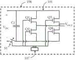
参照图4,在本发明的另一实施方式中,包括MOSFET Q1、Q2、Q3、Q4和电容器C1在内的各个H桥101与开关S1和对MOSFET和开关S1进行操作的微控制器107一起安装在PCB106上。印刷电路板与其相应的面板集成使得能够省略DC布线和线缆。在一个实施方式中,PCB集成在PV面板的连接盒中。为了创建本发明级联的H桥转换器,将承载H桥的多个PCB级联连接。Referring to Figure 4, in another embodiment of the present invention, each H-
图5示出本发明进一步的方面,其中提供了完整的光伏系统。光伏系统200包括:多个PV面板108、109、110、111。相应的H桥转换器101、102、103、104与每个PV面板集成,优选地集成在各个板的连接盒中。从PV面板向每个H桥转换器提供DC电压VDC1、VDC2、VDC3、VDC4。H桥转换器被进一步级联以产生多电平电压输出VOUT。进一步地,为了产生该多电平电压输出,DC-AC逆变器包括开关控制电路(以如之前描述以微控制器的形式实现)来控制其切换。进一步地,PV系统200包括连接到级联的H桥转换器的中央调节单元105,以调节该多电平电压输出使得从该系统中输出AC电网电压VAC,。在其最简单的形式中,利用吸收在该系统和电网之间的不可避免的电压失配的电感器L1来实现中央调节单元。通常距PV面板远程地设置中央调节单元,例如设置在中央监控台处。在遮荫的情况下,为了将H桥与其PV面板断开,该PV系统可以包括以上讨论的开关。Figure 5 shows a further aspect of the invention, where a complete photovoltaic system is provided. The
应当注意的是,如以上在本发明的具体实施方式中已经讨论的中央调节单元105可以包括比电感器更多的智能。例如,中央单元可包括用于经由有线通信通道或无线通信通道与各个PCB通信的微控制器。中央调节单元进一步地或另选地包括一个或多个接地故障断路器和诸如防孤岛电路这样的其它安全组件。此外,中央调节单元可包括用于执行系统诊断的电流和电压测量电路。It should be noted that the
Claims (10)
Applications Claiming Priority (5)
| Application Number | Priority Date | Filing Date | Title |
|---|---|---|---|
| SE1150791-0 | 2011-08-31 | ||
| SE1150791 | 2011-08-31 | ||
| US201161533241P | 2011-09-11 | 2011-09-11 | |
| US61/533,241 | 2011-09-11 | ||
| PCT/EP2012/066782WO2013030236A2 (en) | 2011-08-31 | 2012-08-29 | Dc-ac inverter for photovoltaic systems |
Publications (2)
| Publication Number | Publication Date |
|---|---|
| CN103828217Atrue CN103828217A (en) | 2014-05-28 |
| CN103828217B CN103828217B (en) | 2016-10-12 |
Family
ID=47756977
Family Applications (1)
| Application Number | Title | Priority Date | Filing Date |
|---|---|---|---|
| CN201280041767.8AExpired - Fee RelatedCN103828217B (en) | 2011-08-31 | 2012-08-29 | There is the photovoltaic DC/AC inverter of the H bridge transducer of cascade |
Country Status (8)
| Country | Link |
|---|---|
| US (1) | US9685886B2 (en) |
| EP (1) | EP2751920A2 (en) |
| JP (2) | JP6294824B2 (en) |
| CN (1) | CN103828217B (en) |
| BR (1) | BR112014004876A2 (en) |
| CA (1) | CA2845664C (en) |
| WO (1) | WO2013030236A2 (en) |
| ZA (1) | ZA201401207B (en) |
Cited By (10)
| Publication number | Priority date | Publication date | Assignee | Title |
|---|---|---|---|---|
| CN104333247A (en)* | 2014-10-13 | 2015-02-04 | 华南理工大学 | Cascaded multilevel single-phase inverter and cascaded multilevel three-phase inverter adopting novel three-terminal switching networks |
| CN104460804A (en)* | 2014-12-11 | 2015-03-25 | 无锡市锡容电力电器有限公司 | Small current generating device and reactive compensation device debugging system comprising same |
| CN105140966A (en)* | 2015-10-12 | 2015-12-09 | 国网天津市电力公司 | Modulation strategy for suppressing non-isolated photovoltaic system leakage current |
| CN105720857A (en)* | 2016-04-22 | 2016-06-29 | 阳光电源股份有限公司 | Cascaded H bridge inverter and fault handling method thereof |
| CN106611962A (en)* | 2015-10-27 | 2017-05-03 | 上海交通大学 | Chain type cascaded self-synchronizing photovoltaic power generation controlling device and method |
| CN106712561A (en)* | 2016-08-30 | 2017-05-24 | 阳光电源股份有限公司 | Control method and device for cascade H bridge inverter |
| CN107733269A (en)* | 2017-10-12 | 2018-02-23 | 合肥工业大学 | Square wave compensation control method for expanding the operating range of cascaded H-bridge photovoltaic inverters |
| CN108702106A (en)* | 2016-01-14 | 2018-10-23 | 捷普有限公司 | Low Voltage Low Frequency Multilevel Power Converter |
| CN110971136A (en)* | 2018-10-01 | 2020-04-07 | Abb瑞士股份有限公司 | Inverter device using photovoltaic energy transfer element |
| CN112467981A (en)* | 2019-09-06 | 2021-03-09 | Abb瑞士股份有限公司 | Boost modular multilevel converter |
Families Citing this family (34)
| Publication number | Priority date | Publication date | Assignee | Title |
|---|---|---|---|---|
| US9418864B2 (en) | 2008-01-30 | 2016-08-16 | Infineon Technologies Ag | Method of forming a non volatile memory device using wet etching |
| US9685886B2 (en)* | 2011-08-31 | 2017-06-20 | Optistring Technologies Ab | Photovoltaic DC/AC inverter with cascaded H-bridge converters |
| US9478989B2 (en) | 2012-01-17 | 2016-10-25 | Infineon Technologies Austria Ag | Power converter circuit with AC output |
| US9425622B2 (en) | 2013-01-08 | 2016-08-23 | Infineon Technologies Austria Ag | Power converter circuit with AC output and at least one transformer |
| US9461474B2 (en) | 2012-01-17 | 2016-10-04 | Infineon Technologies Austria Ag | Power converter circuit with AC output |
| US9401663B2 (en) | 2012-12-21 | 2016-07-26 | Infineon Technologies Austria Ag | Power converter circuit with AC output |
| US9484746B2 (en) | 2012-01-17 | 2016-11-01 | Infineon Technologies Austria Ag | Power converter circuit with AC output |
| EP2773036B1 (en)* | 2013-02-27 | 2016-02-24 | Optistring Technologies AB | Method for DC-AC conversion |
| US20160218637A1 (en)* | 2013-09-23 | 2016-07-28 | Siemens Aktiengesellschaft . | A new four-level converter cell topology for cascaded modular multilevel converters |
| CN104052325B (en)* | 2014-06-05 | 2016-07-06 | 上海交通大学 | The method for designing of the cascade multilevel inverter that voltage distortion minimizes on a large scale |
| US10135362B2 (en)* | 2014-07-14 | 2018-11-20 | Alexander Philip Davies | Method for controlling a power conversion system |
| KR101697855B1 (en)* | 2015-03-30 | 2017-01-19 | 숭실대학교산학협력단 | H-bridge multi-level inverter |
| AU2016318966B2 (en)* | 2015-09-11 | 2018-12-06 | Innomotics Gmbh | Printed circuit board power cell with isolation and medium voltage multi-cell power supply |
| US10218285B2 (en) | 2015-10-19 | 2019-02-26 | Siemens Aktiengesellschaft | Medium voltage hybrid multilevel converter and method for controlling a medium voltage hybrid multilevel converter |
| SE539353C2 (en) | 2015-11-18 | 2017-07-25 | Optistring Tech Ab | Combined common mode inductor and differential signal transformer |
| SE539911C2 (en)* | 2015-11-18 | 2018-01-09 | Optistring Tech Ab | Common line communication in cascaded inverters |
| CN106253334B (en)* | 2016-08-19 | 2018-12-28 | 阳光电源股份有限公司 | A kind of Cascade-type photovoltaic grid-connected inverter and its control method and control device |
| CN106602999B (en)* | 2016-12-21 | 2019-01-18 | 湖北工业大学 | A kind of Mixed cascading type photovoltaic inverter and control method based on super capacitor energy-storage |
| US10186995B2 (en) | 2017-01-13 | 2019-01-22 | General Electric Company | Rotating switching strategy for power converters |
| US10148205B2 (en) | 2017-02-02 | 2018-12-04 | General Electric Company | Control method for power converters with inverter blocks with silicon carbide MOSFETs |
| JP7398961B2 (en) | 2017-06-12 | 2023-12-15 | ティーエーイー テクノロジーズ, インコーポレイテッド | Multi-level multi-quadrant hysteresis current controller and method for its control |
| EP3639361A4 (en) | 2017-06-16 | 2021-03-24 | TAE Technologies, Inc. | Multi-level hysteresis voltage controllers for voltage modulators and methods for control thereof |
| CN107947229B (en) | 2017-11-28 | 2020-07-07 | 阳光电源股份有限公司 | Control method and device for alternating current cascade photovoltaic power generation system |
| KR20200135399A (en) | 2018-03-22 | 2020-12-02 | 티에이이 테크놀로지스, 인크. | Systems and methods for power management and control |
| EP3949063A4 (en) | 2019-03-29 | 2023-03-01 | TAE Technologies, Inc. | MODULE-BASED ENERGY SYSTEMS WITH CONVERTER SOURCE MODULES AND METHODS THEREOF |
| AU2021254739A1 (en) | 2020-04-14 | 2022-12-01 | Tae Technologies, Inc. | Modular cascaded energy systems with a cooling apparatus and with replaceable energy source capability |
| CA3191441A1 (en) | 2020-04-14 | 2021-10-21 | Tae Technologies, Inc. | Systems, devices, and methods for charging and discharging module-based cascaded energy systems |
| AU2021271701A1 (en) | 2020-05-14 | 2022-12-22 | Tae Technologies, Inc. | Systems, devices, and methods for rail-based and other electric vehicles with modular cascaded energy systems |
| US20240359595A1 (en)* | 2020-08-24 | 2024-10-31 | Tae Technologies, Inc. | Modular Cascaded Energy Systems with a Cooling Apparatus and with Replaceable Energy Source Capability |
| US11923782B2 (en) | 2020-09-28 | 2024-03-05 | Tae Technologies, Inc. | Multi-phase module-based energy system frameworks and methods related thereto |
| JP2023543834A (en) | 2020-09-30 | 2023-10-18 | ティーエーイー テクノロジーズ, インコーポレイテッド | Systems, devices, and methods for intraphase and interphase equilibrium in module-based cascaded energy systems |
| CA3207256A1 (en) | 2021-01-13 | 2022-07-21 | Tae Technologies, Inc. | Systems, devices, and methods for module-based cascaded energy systems |
| JP2024528571A (en) | 2021-07-07 | 2024-07-30 | ティーエーイー テクノロジーズ, インコーポレイテッド | Systems, devices, and methods for a modular-based cascaded energy system configured to interface with renewable energy sources - Patents.com |
| CN218449870U (en)* | 2022-10-12 | 2023-02-03 | 阳光电源股份有限公司 | Multi-path independent input micro inverter and photovoltaic system |
Citations (3)
| Publication number | Priority date | Publication date | Assignee | Title |
|---|---|---|---|---|
| US4052657A (en)* | 1976-04-22 | 1977-10-04 | Rockwell International Corporation | Distribution system for a. c. electrical energy derived from d. c. energy sources |
| US20080078436A1 (en)* | 2006-09-28 | 2008-04-03 | Jack Nachamkin | Integrated voltaic energy system |
| CN101488668A (en)* | 2008-04-30 | 2009-07-22 | 江苏南自通华新能源电力有限公司 | Reconfigurable distributed access grid-connected inverter |
Family Cites Families (14)
| Publication number | Priority date | Publication date | Assignee | Title |
|---|---|---|---|---|
| JPH01238434A (en)* | 1988-03-16 | 1989-09-22 | Fuji Electric Co Ltd | Output control circuit for grid-connected inverter |
| DE19709766C1 (en)* | 1997-03-10 | 1998-09-03 | Siemens Ag | Controlling several coupled end stages esp. with gradient amplifier of nuclear resonance tomography e.g. Project 039 |
| JPH11312022A (en) | 1998-04-28 | 1999-11-09 | Yaskawa Electric Corp | Photovoltaic power generation inverter device and control method thereof |
| US6111767A (en)* | 1998-06-22 | 2000-08-29 | Heliotronics, Inc. | Inverter integrated instrumentation having a current-voltage curve tracer |
| JP3697121B2 (en)* | 1998-10-15 | 2005-09-21 | キヤノン株式会社 | Photovoltaic power generation apparatus and control method thereof |
| JP2001223377A (en) | 2000-02-07 | 2001-08-17 | Kyocera Corp | Snow melting control method for photovoltaic power generator |
| DE102005045957A1 (en)* | 2005-09-26 | 2006-11-16 | Siemens Ag | Signal transmission method between a central control and decentralized controls and device uses power semiconductor having at least two switch condition and radio or light guide transmission |
| JP4134192B2 (en)* | 2006-04-25 | 2008-08-13 | 株式会社をくだ屋技研 | Overcharge protection device for battery working vehicle |
| EP2156542B1 (en) | 2007-06-04 | 2016-03-30 | Sustainable Energy Technologies | Prediction scheme for step wave power converter and inductive inverter topology |
| US20100116325A1 (en)* | 2008-11-12 | 2010-05-13 | Mehrdad Nikoonahad | High efficiency solar panel and system |
| JP5391872B2 (en)* | 2009-06-29 | 2014-01-15 | Tdk株式会社 | Multiple power supply control system and power conversion device |
| US8772965B2 (en)* | 2010-06-29 | 2014-07-08 | General Electric Company | Solar power generation system and method |
| US20120176076A1 (en)* | 2011-01-10 | 2012-07-12 | Carl Mansfield | Methods and systems for powering auxiliary devices in photovol taic system |
| US9685886B2 (en)* | 2011-08-31 | 2017-06-20 | Optistring Technologies Ab | Photovoltaic DC/AC inverter with cascaded H-bridge converters |
- 2012
- 2012-08-29USUS14/342,381patent/US9685886B2/ennot_activeExpired - Fee Related
- 2012-08-29EPEP12753959.1Apatent/EP2751920A2/ennot_activeCeased
- 2012-08-29BRBR112014004876Apatent/BR112014004876A2/enactiveSearch and Examination
- 2012-08-29CNCN201280041767.8Apatent/CN103828217B/ennot_activeExpired - Fee Related
- 2012-08-29JPJP2014527646Apatent/JP6294824B2/ennot_activeExpired - Fee Related
- 2012-08-29WOPCT/EP2012/066782patent/WO2013030236A2/enactiveApplication Filing
- 2012-08-29CACA2845664Apatent/CA2845664C/ennot_activeExpired - Fee Related
- 2014
- 2014-02-18ZAZA2014/01207Apatent/ZA201401207B/enunknown
- 2017
- 2017-10-02JPJP2017192334Apatent/JP2018029467A/enactivePending
Patent Citations (3)
| Publication number | Priority date | Publication date | Assignee | Title |
|---|---|---|---|---|
| US4052657A (en)* | 1976-04-22 | 1977-10-04 | Rockwell International Corporation | Distribution system for a. c. electrical energy derived from d. c. energy sources |
| US20080078436A1 (en)* | 2006-09-28 | 2008-04-03 | Jack Nachamkin | Integrated voltaic energy system |
| CN101488668A (en)* | 2008-04-30 | 2009-07-22 | 江苏南自通华新能源电力有限公司 | Reconfigurable distributed access grid-connected inverter |
Non-Patent Citations (1)
| Title |
|---|
| ABDUL RAHIMAN BEIG等: "A Novel Fifteen Level Inverter for Photovoltaic Power Supply System", 《INDUSTRY APPLICATIONS CONFERENCE》, 3 October 2004 (2004-10-03)* |
Cited By (17)
| Publication number | Priority date | Publication date | Assignee | Title |
|---|---|---|---|---|
| CN104333247A (en)* | 2014-10-13 | 2015-02-04 | 华南理工大学 | Cascaded multilevel single-phase inverter and cascaded multilevel three-phase inverter adopting novel three-terminal switching networks |
| CN104460804A (en)* | 2014-12-11 | 2015-03-25 | 无锡市锡容电力电器有限公司 | Small current generating device and reactive compensation device debugging system comprising same |
| CN105140966B (en)* | 2015-10-12 | 2017-06-06 | 国网天津市电力公司 | A kind of modulation strategy for suppressing non-isolation type photovoltaic system leakage current |
| CN105140966A (en)* | 2015-10-12 | 2015-12-09 | 国网天津市电力公司 | Modulation strategy for suppressing non-isolated photovoltaic system leakage current |
| CN106611962B (en)* | 2015-10-27 | 2019-02-26 | 上海交通大学 | A chain cascade self-synchronizing solar photovoltaic power generation control device and control method |
| CN106611962A (en)* | 2015-10-27 | 2017-05-03 | 上海交通大学 | Chain type cascaded self-synchronizing photovoltaic power generation controlling device and method |
| CN108702106A (en)* | 2016-01-14 | 2018-10-23 | 捷普有限公司 | Low Voltage Low Frequency Multilevel Power Converter |
| CN115001298A (en)* | 2016-01-14 | 2022-09-02 | 捷普有限公司 | Low-voltage low-frequency multi-level power converter |
| US12136891B2 (en) | 2016-01-14 | 2024-11-05 | Jabil Inc. | Low voltage, low frequency, multi level power converter |
| US10205403B2 (en) | 2016-04-22 | 2019-02-12 | Sungrow Power Supply Co., Ltd. | Cascaded H-bridge inverter and method for handling fault thereof |
| CN105720857A (en)* | 2016-04-22 | 2016-06-29 | 阳光电源股份有限公司 | Cascaded H bridge inverter and fault handling method thereof |
| CN105720857B (en)* | 2016-04-22 | 2019-12-03 | 阳光电源股份有限公司 | A kind of Cascade H bridge inverter and its fault handling method |
| CN106712561A (en)* | 2016-08-30 | 2017-05-24 | 阳光电源股份有限公司 | Control method and device for cascade H bridge inverter |
| CN106712561B (en)* | 2016-08-30 | 2019-05-31 | 阳光电源股份有限公司 | The control method of Cascade H bridge inverter and the control device of Cascade H bridge inverter |
| CN107733269A (en)* | 2017-10-12 | 2018-02-23 | 合肥工业大学 | Square wave compensation control method for expanding the operating range of cascaded H-bridge photovoltaic inverters |
| CN110971136A (en)* | 2018-10-01 | 2020-04-07 | Abb瑞士股份有限公司 | Inverter device using photovoltaic energy transfer element |
| CN112467981A (en)* | 2019-09-06 | 2021-03-09 | Abb瑞士股份有限公司 | Boost modular multilevel converter |
Also Published As
| Publication number | Publication date |
|---|---|
| JP2018029467A (en) | 2018-02-22 |
| ZA201401207B (en) | 2015-05-27 |
| EP2751920A2 (en) | 2014-07-09 |
| JP6294824B2 (en) | 2018-03-14 |
| JP2014525730A (en) | 2014-09-29 |
| BR112014004876A2 (en) | 2017-04-04 |
| CA2845664C (en) | 2019-04-23 |
| WO2013030236A3 (en) | 2013-09-06 |
| WO2013030236A2 (en) | 2013-03-07 |
| US9685886B2 (en) | 2017-06-20 |
| US20150340964A1 (en) | 2015-11-26 |
| CN103828217B (en) | 2016-10-12 |
| CA2845664A1 (en) | 2013-03-07 |
Similar Documents
| Publication | Publication Date | Title |
|---|---|---|
| CN103828217B (en) | There is the photovoltaic DC/AC inverter of the H bridge transducer of cascade | |
| AU2022203915B2 (en) | Systems and methods of DC Power Conversion and Transmission for Solar Fields | |
| JP4322250B2 (en) | Transformer-less grid-connected power conversion circuit | |
| CN108233421B (en) | Photovoltaic power generation system and photovoltaic power transmission method | |
| US20200036191A1 (en) | Distributed substring architecture for maximum power point tracking of energy sources | |
| US7064969B2 (en) | Monopolar DC to bipolar to AC converter | |
| EP2807737B1 (en) | Stacked voltage source inverter with separate dc sources | |
| CN102315798A (en) | Solar power system and method | |
| US20140333141A1 (en) | Photovoltaic (pv)-based ac module and solar systems therefrom | |
| US12136871B2 (en) | Power supply system | |
| US12074444B2 (en) | Power system | |
| EP2882090A1 (en) | Single-phase fullbridge inverter with switchable output filter | |
| CN104242349A (en) | Photovoltaic system with potential induced degradation prevention function and photovoltaic inverter | |
| US11146072B2 (en) | Inverter with at least two DC/DC converters and use of such an inverter in a photovoltaic installation | |
| KR20210121588A (en) | Differential power conditioning system for improving performance of photovoltaic power generation system | |
| Purgat et al. | Power flow control converter for meshed LVDC distribution grids | |
| CN110535172B (en) | Alternating current-direct current wind-solar hybrid power generation system and power smooth control method | |
| CN113162414B (en) | Base unit for electric energy converter, electric energy converter and universal power interface | |
| Zeltner et al. | Power electronics for smart micro and nano grids controlled by a novel two-wire interface with integrated power and signal transfer | |
| Lu et al. | Two-transistor step-down dc/dc converters with fault-tolerant capability | |
| CN204578455U (en) | A kind of photovoltaic combining inverter | |
| KR20230006276A (en) | Switching loss balancing circuit |
Legal Events
| Date | Code | Title | Description |
|---|---|---|---|
| C06 | Publication | ||
| PB01 | Publication | ||
| C10 | Entry into substantive examination | ||
| SE01 | Entry into force of request for substantive examination | ||
| C14 | Grant of patent or utility model | ||
| GR01 | Patent grant | ||
| TR01 | Transfer of patent right | Effective date of registration:20171212 Address after:Baden, Switzerland Patentee after:ABB TECHNOLOGY AG Address before:Stockholm Patentee before:OPTISTRING TECHNOLOGIES AB | |
| TR01 | Transfer of patent right | ||
| TR01 | Transfer of patent right | Effective date of registration:20201116 Address after:Rotterdam Patentee after:Marich holdings Netherlands Ltd. Address before:Baden, Switzerland Patentee before:ABB TECHNOLOGY AG | |
| TR01 | Transfer of patent right | ||
| CF01 | Termination of patent right due to non-payment of annual fee | Granted publication date:20161012 | |
| CF01 | Termination of patent right due to non-payment of annual fee |