CN103828181A - Multiport Vehicle DC Charging System with Variable Power Distribution - Google Patents
Multiport Vehicle DC Charging System with Variable Power DistributionDownload PDFInfo
- Publication number
- CN103828181A CN103828181ACN201280041847.3ACN201280041847ACN103828181ACN 103828181 ACN103828181 ACN 103828181ACN 201280041847 ACN201280041847 ACN 201280041847ACN 103828181 ACN103828181 ACN 103828181A
- Authority
- CN
- China
- Prior art keywords
- power
- charging
- vehicle
- charging station
- port
- Prior art date
- Legal status (The legal status is an assumption and is not a legal conclusion. Google has not performed a legal analysis and makes no representation as to the accuracy of the status listed.)
- Granted
Links
Images


Classifications
- B—PERFORMING OPERATIONS; TRANSPORTING
- B60—VEHICLES IN GENERAL
- B60L—PROPULSION OF ELECTRICALLY-PROPELLED VEHICLES; SUPPLYING ELECTRIC POWER FOR AUXILIARY EQUIPMENT OF ELECTRICALLY-PROPELLED VEHICLES; ELECTRODYNAMIC BRAKE SYSTEMS FOR VEHICLES IN GENERAL; MAGNETIC SUSPENSION OR LEVITATION FOR VEHICLES; MONITORING OPERATING VARIABLES OF ELECTRICALLY-PROPELLED VEHICLES; ELECTRIC SAFETY DEVICES FOR ELECTRICALLY-PROPELLED VEHICLES
- B60L1/00—Supplying electric power to auxiliary equipment of vehicles
- B60L1/003—Supplying electric power to auxiliary equipment of vehicles to auxiliary motors, e.g. for pumps, compressors
- H02J7/0027—
- B—PERFORMING OPERATIONS; TRANSPORTING
- B60—VEHICLES IN GENERAL
- B60L—PROPULSION OF ELECTRICALLY-PROPELLED VEHICLES; SUPPLYING ELECTRIC POWER FOR AUXILIARY EQUIPMENT OF ELECTRICALLY-PROPELLED VEHICLES; ELECTRODYNAMIC BRAKE SYSTEMS FOR VEHICLES IN GENERAL; MAGNETIC SUSPENSION OR LEVITATION FOR VEHICLES; MONITORING OPERATING VARIABLES OF ELECTRICALLY-PROPELLED VEHICLES; ELECTRIC SAFETY DEVICES FOR ELECTRICALLY-PROPELLED VEHICLES
- B60L53/00—Methods of charging batteries, specially adapted for electric vehicles; Charging stations or on-board charging equipment therefor; Exchange of energy storage elements in electric vehicles
- B60L53/10—Methods of charging batteries, specially adapted for electric vehicles; Charging stations or on-board charging equipment therefor; Exchange of energy storage elements in electric vehicles characterised by the energy transfer between the charging station and the vehicle
- B60L53/11—DC charging controlled by the charging station, e.g. mode 4
- B—PERFORMING OPERATIONS; TRANSPORTING
- B60—VEHICLES IN GENERAL
- B60L—PROPULSION OF ELECTRICALLY-PROPELLED VEHICLES; SUPPLYING ELECTRIC POWER FOR AUXILIARY EQUIPMENT OF ELECTRICALLY-PROPELLED VEHICLES; ELECTRODYNAMIC BRAKE SYSTEMS FOR VEHICLES IN GENERAL; MAGNETIC SUSPENSION OR LEVITATION FOR VEHICLES; MONITORING OPERATING VARIABLES OF ELECTRICALLY-PROPELLED VEHICLES; ELECTRIC SAFETY DEVICES FOR ELECTRICALLY-PROPELLED VEHICLES
- B60L53/00—Methods of charging batteries, specially adapted for electric vehicles; Charging stations or on-board charging equipment therefor; Exchange of energy storage elements in electric vehicles
- B60L53/10—Methods of charging batteries, specially adapted for electric vehicles; Charging stations or on-board charging equipment therefor; Exchange of energy storage elements in electric vehicles characterised by the energy transfer between the charging station and the vehicle
- B60L53/14—Conductive energy transfer
- B—PERFORMING OPERATIONS; TRANSPORTING
- B60—VEHICLES IN GENERAL
- B60L—PROPULSION OF ELECTRICALLY-PROPELLED VEHICLES; SUPPLYING ELECTRIC POWER FOR AUXILIARY EQUIPMENT OF ELECTRICALLY-PROPELLED VEHICLES; ELECTRODYNAMIC BRAKE SYSTEMS FOR VEHICLES IN GENERAL; MAGNETIC SUSPENSION OR LEVITATION FOR VEHICLES; MONITORING OPERATING VARIABLES OF ELECTRICALLY-PROPELLED VEHICLES; ELECTRIC SAFETY DEVICES FOR ELECTRICALLY-PROPELLED VEHICLES
- B60L53/00—Methods of charging batteries, specially adapted for electric vehicles; Charging stations or on-board charging equipment therefor; Exchange of energy storage elements in electric vehicles
- B60L53/30—Constructional details of charging stations
- B60L53/305—Communication interfaces
- B—PERFORMING OPERATIONS; TRANSPORTING
- B60—VEHICLES IN GENERAL
- B60L—PROPULSION OF ELECTRICALLY-PROPELLED VEHICLES; SUPPLYING ELECTRIC POWER FOR AUXILIARY EQUIPMENT OF ELECTRICALLY-PROPELLED VEHICLES; ELECTRODYNAMIC BRAKE SYSTEMS FOR VEHICLES IN GENERAL; MAGNETIC SUSPENSION OR LEVITATION FOR VEHICLES; MONITORING OPERATING VARIABLES OF ELECTRICALLY-PROPELLED VEHICLES; ELECTRIC SAFETY DEVICES FOR ELECTRICALLY-PROPELLED VEHICLES
- B60L53/00—Methods of charging batteries, specially adapted for electric vehicles; Charging stations or on-board charging equipment therefor; Exchange of energy storage elements in electric vehicles
- B60L53/60—Monitoring or controlling charging stations
- B60L53/63—Monitoring or controlling charging stations in response to network capacity
- B—PERFORMING OPERATIONS; TRANSPORTING
- B60—VEHICLES IN GENERAL
- B60L—PROPULSION OF ELECTRICALLY-PROPELLED VEHICLES; SUPPLYING ELECTRIC POWER FOR AUXILIARY EQUIPMENT OF ELECTRICALLY-PROPELLED VEHICLES; ELECTRODYNAMIC BRAKE SYSTEMS FOR VEHICLES IN GENERAL; MAGNETIC SUSPENSION OR LEVITATION FOR VEHICLES; MONITORING OPERATING VARIABLES OF ELECTRICALLY-PROPELLED VEHICLES; ELECTRIC SAFETY DEVICES FOR ELECTRICALLY-PROPELLED VEHICLES
- B60L53/00—Methods of charging batteries, specially adapted for electric vehicles; Charging stations or on-board charging equipment therefor; Exchange of energy storage elements in electric vehicles
- B60L53/60—Monitoring or controlling charging stations
- B60L53/64—Optimising energy costs, e.g. responding to electricity rates
- B—PERFORMING OPERATIONS; TRANSPORTING
- B60—VEHICLES IN GENERAL
- B60L—PROPULSION OF ELECTRICALLY-PROPELLED VEHICLES; SUPPLYING ELECTRIC POWER FOR AUXILIARY EQUIPMENT OF ELECTRICALLY-PROPELLED VEHICLES; ELECTRODYNAMIC BRAKE SYSTEMS FOR VEHICLES IN GENERAL; MAGNETIC SUSPENSION OR LEVITATION FOR VEHICLES; MONITORING OPERATING VARIABLES OF ELECTRICALLY-PROPELLED VEHICLES; ELECTRIC SAFETY DEVICES FOR ELECTRICALLY-PROPELLED VEHICLES
- B60L53/00—Methods of charging batteries, specially adapted for electric vehicles; Charging stations or on-board charging equipment therefor; Exchange of energy storage elements in electric vehicles
- B60L53/60—Monitoring or controlling charging stations
- B60L53/65—Monitoring or controlling charging stations involving identification of vehicles or their battery types
- B—PERFORMING OPERATIONS; TRANSPORTING
- B60—VEHICLES IN GENERAL
- B60L—PROPULSION OF ELECTRICALLY-PROPELLED VEHICLES; SUPPLYING ELECTRIC POWER FOR AUXILIARY EQUIPMENT OF ELECTRICALLY-PROPELLED VEHICLES; ELECTRODYNAMIC BRAKE SYSTEMS FOR VEHICLES IN GENERAL; MAGNETIC SUSPENSION OR LEVITATION FOR VEHICLES; MONITORING OPERATING VARIABLES OF ELECTRICALLY-PROPELLED VEHICLES; ELECTRIC SAFETY DEVICES FOR ELECTRICALLY-PROPELLED VEHICLES
- B60L53/00—Methods of charging batteries, specially adapted for electric vehicles; Charging stations or on-board charging equipment therefor; Exchange of energy storage elements in electric vehicles
- B60L53/60—Monitoring or controlling charging stations
- B60L53/66—Data transfer between charging stations and vehicles
- B60L53/665—Methods related to measuring, billing or payment
- B—PERFORMING OPERATIONS; TRANSPORTING
- B60—VEHICLES IN GENERAL
- B60L—PROPULSION OF ELECTRICALLY-PROPELLED VEHICLES; SUPPLYING ELECTRIC POWER FOR AUXILIARY EQUIPMENT OF ELECTRICALLY-PROPELLED VEHICLES; ELECTRODYNAMIC BRAKE SYSTEMS FOR VEHICLES IN GENERAL; MAGNETIC SUSPENSION OR LEVITATION FOR VEHICLES; MONITORING OPERATING VARIABLES OF ELECTRICALLY-PROPELLED VEHICLES; ELECTRIC SAFETY DEVICES FOR ELECTRICALLY-PROPELLED VEHICLES
- B60L58/00—Methods or circuit arrangements for monitoring or controlling batteries or fuel cells, specially adapted for electric vehicles
- B60L58/10—Methods or circuit arrangements for monitoring or controlling batteries or fuel cells, specially adapted for electric vehicles for monitoring or controlling batteries
- B60L58/12—Methods or circuit arrangements for monitoring or controlling batteries or fuel cells, specially adapted for electric vehicles for monitoring or controlling batteries responding to state of charge [SoC]
- H—ELECTRICITY
- H02—GENERATION; CONVERSION OR DISTRIBUTION OF ELECTRIC POWER
- H02J—CIRCUIT ARRANGEMENTS OR SYSTEMS FOR SUPPLYING OR DISTRIBUTING ELECTRIC POWER; SYSTEMS FOR STORING ELECTRIC ENERGY
- H02J7/00—Circuit arrangements for charging or depolarising batteries or for supplying loads from batteries
- H02J7/0013—Circuit arrangements for charging or depolarising batteries or for supplying loads from batteries acting upon several batteries simultaneously or sequentially
- H—ELECTRICITY
- H02—GENERATION; CONVERSION OR DISTRIBUTION OF ELECTRIC POWER
- H02J—CIRCUIT ARRANGEMENTS OR SYSTEMS FOR SUPPLYING OR DISTRIBUTING ELECTRIC POWER; SYSTEMS FOR STORING ELECTRIC ENERGY
- H02J7/00—Circuit arrangements for charging or depolarising batteries or for supplying loads from batteries
- H02J7/0042—Circuit arrangements for charging or depolarising batteries or for supplying loads from batteries characterised by the mechanical construction
- H—ELECTRICITY
- H02—GENERATION; CONVERSION OR DISTRIBUTION OF ELECTRIC POWER
- H02J—CIRCUIT ARRANGEMENTS OR SYSTEMS FOR SUPPLYING OR DISTRIBUTING ELECTRIC POWER; SYSTEMS FOR STORING ELECTRIC ENERGY
- H02J7/00—Circuit arrangements for charging or depolarising batteries or for supplying loads from batteries
- H02J7/02—Circuit arrangements for charging or depolarising batteries or for supplying loads from batteries for charging batteries from AC mains by converters
- B—PERFORMING OPERATIONS; TRANSPORTING
- B60—VEHICLES IN GENERAL
- B60L—PROPULSION OF ELECTRICALLY-PROPELLED VEHICLES; SUPPLYING ELECTRIC POWER FOR AUXILIARY EQUIPMENT OF ELECTRICALLY-PROPELLED VEHICLES; ELECTRODYNAMIC BRAKE SYSTEMS FOR VEHICLES IN GENERAL; MAGNETIC SUSPENSION OR LEVITATION FOR VEHICLES; MONITORING OPERATING VARIABLES OF ELECTRICALLY-PROPELLED VEHICLES; ELECTRIC SAFETY DEVICES FOR ELECTRICALLY-PROPELLED VEHICLES
- B60L2200/00—Type of vehicles
- B60L2200/40—Working vehicles
- B60L2200/42—Fork lift trucks
- B—PERFORMING OPERATIONS; TRANSPORTING
- B60—VEHICLES IN GENERAL
- B60L—PROPULSION OF ELECTRICALLY-PROPELLED VEHICLES; SUPPLYING ELECTRIC POWER FOR AUXILIARY EQUIPMENT OF ELECTRICALLY-PROPELLED VEHICLES; ELECTRODYNAMIC BRAKE SYSTEMS FOR VEHICLES IN GENERAL; MAGNETIC SUSPENSION OR LEVITATION FOR VEHICLES; MONITORING OPERATING VARIABLES OF ELECTRICALLY-PROPELLED VEHICLES; ELECTRIC SAFETY DEVICES FOR ELECTRICALLY-PROPELLED VEHICLES
- B60L2240/00—Control parameters of input or output; Target parameters
- B60L2240/10—Vehicle control parameters
- B60L2240/34—Cabin temperature
- B—PERFORMING OPERATIONS; TRANSPORTING
- B60—VEHICLES IN GENERAL
- B60L—PROPULSION OF ELECTRICALLY-PROPELLED VEHICLES; SUPPLYING ELECTRIC POWER FOR AUXILIARY EQUIPMENT OF ELECTRICALLY-PROPELLED VEHICLES; ELECTRODYNAMIC BRAKE SYSTEMS FOR VEHICLES IN GENERAL; MAGNETIC SUSPENSION OR LEVITATION FOR VEHICLES; MONITORING OPERATING VARIABLES OF ELECTRICALLY-PROPELLED VEHICLES; ELECTRIC SAFETY DEVICES FOR ELECTRICALLY-PROPELLED VEHICLES
- B60L2240/00—Control parameters of input or output; Target parameters
- B60L2240/40—Drive Train control parameters
- B60L2240/54—Drive Train control parameters related to batteries
- B60L2240/545—Temperature
- B—PERFORMING OPERATIONS; TRANSPORTING
- B60—VEHICLES IN GENERAL
- B60L—PROPULSION OF ELECTRICALLY-PROPELLED VEHICLES; SUPPLYING ELECTRIC POWER FOR AUXILIARY EQUIPMENT OF ELECTRICALLY-PROPELLED VEHICLES; ELECTRODYNAMIC BRAKE SYSTEMS FOR VEHICLES IN GENERAL; MAGNETIC SUSPENSION OR LEVITATION FOR VEHICLES; MONITORING OPERATING VARIABLES OF ELECTRICALLY-PROPELLED VEHICLES; ELECTRIC SAFETY DEVICES FOR ELECTRICALLY-PROPELLED VEHICLES
- B60L2240/00—Control parameters of input or output; Target parameters
- B60L2240/80—Time limits
- B—PERFORMING OPERATIONS; TRANSPORTING
- B60—VEHICLES IN GENERAL
- B60L—PROPULSION OF ELECTRICALLY-PROPELLED VEHICLES; SUPPLYING ELECTRIC POWER FOR AUXILIARY EQUIPMENT OF ELECTRICALLY-PROPELLED VEHICLES; ELECTRODYNAMIC BRAKE SYSTEMS FOR VEHICLES IN GENERAL; MAGNETIC SUSPENSION OR LEVITATION FOR VEHICLES; MONITORING OPERATING VARIABLES OF ELECTRICALLY-PROPELLED VEHICLES; ELECTRIC SAFETY DEVICES FOR ELECTRICALLY-PROPELLED VEHICLES
- B60L2250/00—Driver interactions
- B60L2250/14—Driver interactions by input of vehicle departure time
- H—ELECTRICITY
- H02—GENERATION; CONVERSION OR DISTRIBUTION OF ELECTRIC POWER
- H02J—CIRCUIT ARRANGEMENTS OR SYSTEMS FOR SUPPLYING OR DISTRIBUTING ELECTRIC POWER; SYSTEMS FOR STORING ELECTRIC ENERGY
- H02J2310/00—The network for supplying or distributing electric power characterised by its spatial reach or by the load
- H02J2310/40—The network being an on-board power network, i.e. within a vehicle
- H02J2310/48—The network being an on-board power network, i.e. within a vehicle for electric vehicles [EV] or hybrid vehicles [HEV]
- Y—GENERAL TAGGING OF NEW TECHNOLOGICAL DEVELOPMENTS; GENERAL TAGGING OF CROSS-SECTIONAL TECHNOLOGIES SPANNING OVER SEVERAL SECTIONS OF THE IPC; TECHNICAL SUBJECTS COVERED BY FORMER USPC CROSS-REFERENCE ART COLLECTIONS [XRACs] AND DIGESTS
- Y02—TECHNOLOGIES OR APPLICATIONS FOR MITIGATION OR ADAPTATION AGAINST CLIMATE CHANGE
- Y02E—REDUCTION OF GREENHOUSE GAS [GHG] EMISSIONS, RELATED TO ENERGY GENERATION, TRANSMISSION OR DISTRIBUTION
- Y02E60/00—Enabling technologies; Technologies with a potential or indirect contribution to GHG emissions mitigation
- Y—GENERAL TAGGING OF NEW TECHNOLOGICAL DEVELOPMENTS; GENERAL TAGGING OF CROSS-SECTIONAL TECHNOLOGIES SPANNING OVER SEVERAL SECTIONS OF THE IPC; TECHNICAL SUBJECTS COVERED BY FORMER USPC CROSS-REFERENCE ART COLLECTIONS [XRACs] AND DIGESTS
- Y02—TECHNOLOGIES OR APPLICATIONS FOR MITIGATION OR ADAPTATION AGAINST CLIMATE CHANGE
- Y02T—CLIMATE CHANGE MITIGATION TECHNOLOGIES RELATED TO TRANSPORTATION
- Y02T10/00—Road transport of goods or passengers
- Y02T10/60—Other road transportation technologies with climate change mitigation effect
- Y02T10/70—Energy storage systems for electromobility, e.g. batteries
- Y—GENERAL TAGGING OF NEW TECHNOLOGICAL DEVELOPMENTS; GENERAL TAGGING OF CROSS-SECTIONAL TECHNOLOGIES SPANNING OVER SEVERAL SECTIONS OF THE IPC; TECHNICAL SUBJECTS COVERED BY FORMER USPC CROSS-REFERENCE ART COLLECTIONS [XRACs] AND DIGESTS
- Y02—TECHNOLOGIES OR APPLICATIONS FOR MITIGATION OR ADAPTATION AGAINST CLIMATE CHANGE
- Y02T—CLIMATE CHANGE MITIGATION TECHNOLOGIES RELATED TO TRANSPORTATION
- Y02T10/00—Road transport of goods or passengers
- Y02T10/60—Other road transportation technologies with climate change mitigation effect
- Y02T10/7072—Electromobility specific charging systems or methods for batteries, ultracapacitors, supercapacitors or double-layer capacitors
- Y—GENERAL TAGGING OF NEW TECHNOLOGICAL DEVELOPMENTS; GENERAL TAGGING OF CROSS-SECTIONAL TECHNOLOGIES SPANNING OVER SEVERAL SECTIONS OF THE IPC; TECHNICAL SUBJECTS COVERED BY FORMER USPC CROSS-REFERENCE ART COLLECTIONS [XRACs] AND DIGESTS
- Y02—TECHNOLOGIES OR APPLICATIONS FOR MITIGATION OR ADAPTATION AGAINST CLIMATE CHANGE
- Y02T—CLIMATE CHANGE MITIGATION TECHNOLOGIES RELATED TO TRANSPORTATION
- Y02T90/00—Enabling technologies or technologies with a potential or indirect contribution to GHG emissions mitigation
- Y02T90/10—Technologies relating to charging of electric vehicles
- Y02T90/12—Electric charging stations
- Y—GENERAL TAGGING OF NEW TECHNOLOGICAL DEVELOPMENTS; GENERAL TAGGING OF CROSS-SECTIONAL TECHNOLOGIES SPANNING OVER SEVERAL SECTIONS OF THE IPC; TECHNICAL SUBJECTS COVERED BY FORMER USPC CROSS-REFERENCE ART COLLECTIONS [XRACs] AND DIGESTS
- Y02—TECHNOLOGIES OR APPLICATIONS FOR MITIGATION OR ADAPTATION AGAINST CLIMATE CHANGE
- Y02T—CLIMATE CHANGE MITIGATION TECHNOLOGIES RELATED TO TRANSPORTATION
- Y02T90/00—Enabling technologies or technologies with a potential or indirect contribution to GHG emissions mitigation
- Y02T90/10—Technologies relating to charging of electric vehicles
- Y02T90/14—Plug-in electric vehicles
- Y—GENERAL TAGGING OF NEW TECHNOLOGICAL DEVELOPMENTS; GENERAL TAGGING OF CROSS-SECTIONAL TECHNOLOGIES SPANNING OVER SEVERAL SECTIONS OF THE IPC; TECHNICAL SUBJECTS COVERED BY FORMER USPC CROSS-REFERENCE ART COLLECTIONS [XRACs] AND DIGESTS
- Y02—TECHNOLOGIES OR APPLICATIONS FOR MITIGATION OR ADAPTATION AGAINST CLIMATE CHANGE
- Y02T—CLIMATE CHANGE MITIGATION TECHNOLOGIES RELATED TO TRANSPORTATION
- Y02T90/00—Enabling technologies or technologies with a potential or indirect contribution to GHG emissions mitigation
- Y02T90/10—Technologies relating to charging of electric vehicles
- Y02T90/16—Information or communication technologies improving the operation of electric vehicles
- Y02T90/167—Systems integrating technologies related to power network operation and communication or information technologies for supporting the interoperability of electric or hybrid vehicles, i.e. smartgrids as interface for battery charging of electric vehicles [EV] or hybrid vehicles [HEV]
- Y—GENERAL TAGGING OF NEW TECHNOLOGICAL DEVELOPMENTS; GENERAL TAGGING OF CROSS-SECTIONAL TECHNOLOGIES SPANNING OVER SEVERAL SECTIONS OF THE IPC; TECHNICAL SUBJECTS COVERED BY FORMER USPC CROSS-REFERENCE ART COLLECTIONS [XRACs] AND DIGESTS
- Y04—INFORMATION OR COMMUNICATION TECHNOLOGIES HAVING AN IMPACT ON OTHER TECHNOLOGY AREAS
- Y04S—SYSTEMS INTEGRATING TECHNOLOGIES RELATED TO POWER NETWORK OPERATION, COMMUNICATION OR INFORMATION TECHNOLOGIES FOR IMPROVING THE ELECTRICAL POWER GENERATION, TRANSMISSION, DISTRIBUTION, MANAGEMENT OR USAGE, i.e. SMART GRIDS
- Y04S10/00—Systems supporting electrical power generation, transmission or distribution
- Y04S10/12—Monitoring or controlling equipment for energy generation units, e.g. distributed energy generation [DER] or load-side generation
- Y04S10/126—Monitoring or controlling equipment for energy generation units, e.g. distributed energy generation [DER] or load-side generation the energy generation units being or involving electric vehicles [EV] or hybrid vehicles [HEV], i.e. power aggregation of EV or HEV, vehicle to grid arrangements [V2G]
- Y—GENERAL TAGGING OF NEW TECHNOLOGICAL DEVELOPMENTS; GENERAL TAGGING OF CROSS-SECTIONAL TECHNOLOGIES SPANNING OVER SEVERAL SECTIONS OF THE IPC; TECHNICAL SUBJECTS COVERED BY FORMER USPC CROSS-REFERENCE ART COLLECTIONS [XRACs] AND DIGESTS
- Y04—INFORMATION OR COMMUNICATION TECHNOLOGIES HAVING AN IMPACT ON OTHER TECHNOLOGY AREAS
- Y04S—SYSTEMS INTEGRATING TECHNOLOGIES RELATED TO POWER NETWORK OPERATION, COMMUNICATION OR INFORMATION TECHNOLOGIES FOR IMPROVING THE ELECTRICAL POWER GENERATION, TRANSMISSION, DISTRIBUTION, MANAGEMENT OR USAGE, i.e. SMART GRIDS
- Y04S30/00—Systems supporting specific end-user applications in the sector of transportation
- Y04S30/10—Systems supporting the interoperability of electric or hybrid vehicles
- Y04S30/14—Details associated with the interoperability, e.g. vehicle recognition, authentication, identification or billing
Landscapes
- Engineering & Computer Science (AREA)
- Power Engineering (AREA)
- Transportation (AREA)
- Mechanical Engineering (AREA)
- Life Sciences & Earth Sciences (AREA)
- Sustainable Development (AREA)
- Sustainable Energy (AREA)
- Charge And Discharge Circuits For Batteries Or The Like (AREA)
- Electric Propulsion And Braking For Vehicles (AREA)
Abstract
Description
Translated fromChinese技术领域technical field
本发明总体上涉及电池充电系统,并且尤其涉及用于分配电力以从单个源向一个或多个电动和混合动力车辆进行充电的方法和装置。The present invention relates generally to battery charging systems, and more particularly to methods and apparatus for distributing electrical power to charge one or more electric and hybrid vehicles from a single source.
背景技术Background technique
如今全球大部分车辆是使用内燃机利用汽油来运转。使用这样的车辆尤其是使用依赖于例如汽油的矿物燃料的车辆产生了两个问题。首先,由于这样的燃料的数量有限以及受限的地区可用性,汽油成本的主要价格的波动以及基本上升的价格趋势是常见的,这二者对于消费者层面都具有剧烈影响。第二,矿物燃料燃烧是二氧化碳(一种温室气体)的主要来源之一,因此是导致全球变暖的主要原因之一。因此,已经在寻找在个人和商业车辆中使用的替代驱动系统方面付出了相当的努力。Most vehicles in the world today run on gasoline using internal combustion engines. Two problems arise with the use of such vehicles, especially with vehicles that rely on fossil fuels such as petrol. First, due to the limited quantity and limited regional availability of such fuels, major price fluctuations in gasoline costs and generally upward price trends are common, both of which have dramatic impacts at the consumer level. Second, the burning of fossil fuels is one of the main sources of carbon dioxide, a greenhouse gas, and therefore one of the main causes of global warming. Accordingly, considerable effort has been devoted to finding alternative drive systems for use in personal and commercial vehicles.
电动车辆由于其更为清洁且更为有效的驱动系统而提供了使用内燃机驱动系的车辆的最具前景的替代形式之一。然而,要获得成功,电动车辆必须要满足用户有关性能、范围、可靠性、寿命和成本的预期。进而,这些预期就使得电动车辆的可充电电池的设计、配置和实施相当重要。很明显,特别是从消费者的角度来看,可充电电池的关键方面是可以在家中、办公地点或公共充电站对电池进行充电的便利性和可靠性。Electric vehicles offer one of the most promising alternatives to vehicles using internal combustion engine drive trains due to their cleaner and more efficient drive systems. However, to be successful, electric vehicles must meet user expectations regarding performance, range, reliability, longevity and cost. These expectations, in turn, make the design, configuration, and implementation of rechargeable batteries for electric vehicles important. Obviously, especially from a consumer point of view, the key aspects of rechargeable batteries are the convenience and reliability of being able to charge the battery at home, at the office or at a public charging station.
在讨论依靠燃油车辆的社会和大幅依赖电动车辆的社会之间的转换时,讨论经常转向对于充电设施需求,该充电设施将使得电动车辆所有者在远离其主要充电站(例如,家庭充电站)时便于对其车辆进行充电。不幸的是,当前的充电设施十分有限。例如,在大型停车场或建筑中,最多会有一个或两个提供接入充电系统以便对电动车辆的电池进行充电的停车位。而这种情况对于当前电动车辆数量可能是足够的,而随着电动车辆更为广泛地被接受,对于更好的充电站接入的需求将变得更为必要。When discussing the transition between a society that relies on gasoline vehicles and a society that relies heavily on electric vehicles, the discussion often turns to the need for charging facilities that would allow electric It is convenient to charge the vehicle at any time. Unfortunately, current charging facilities are very limited. For example, in a large parking lot or building, there may be at most one or two parking spaces that provide access to a charging system for charging the batteries of electric vehicles. While this may be sufficient for the current number of electric vehicles, as electric vehicles become more widely accepted, the need for better access to charging stations will become more necessary.
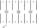
图1图示了一种预期在大型停车场中增加充电站接入能力的一种方法。在该方法中,充电站位于停车场各处而使得每个充电站都处于多个停车位的到达范围之内。例如,在所图示的停车场100的部分中,遍布十二个所图示的停车位分配有三个充电站101-103,因此允许每个充电站处于四个不同车位的范围之内,即充电站101处于车位1、2、7和8的范围内;充电站102处于车位3、4、9和10的范围内;而充电站103处于车位5、6、11和12的范围内。Figure 1 illustrates one approach that is expected to increase charging station access in large car parks. In this method, charging stations are located throughout the parking lot such that each charging station is within reach of a plurality of parking spaces. For example, in the illustrated portion of the
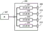
如图1所示的充电站位于停车场或建筑内的中央提供了多部车辆对单个冲电源的物理接入,明显提高了接入能力并因此提高了用户便利性。如果每个充电系统101-103包括多个端口而因此允许同时对多部车辆进行充电,则能够获得进一步的改进。如图2所示,在常规的多端口系统中,通过将四个充电电路201-204整合在单个系统205内而实现了同时充电。充电电路201-204耦合至源207(例如,电网)并且分别耦合至不同车辆端口209-212。在常规的多端口充电站中,充电电路201-204互相独立,即一个充电电路的操作或功率输出并不影响充电站205内的其它充电电路的操作或功率输出。虽然这种方法可以被用来明显改善车辆对于冲电源的接入,但是其由于充电电路201-204的重复而是相对低效且高成本的方法。因此,需要一种从单个充电站对多部车辆同时充电的高效方式。本发明提供了一种这样的充电系统。The charging station shown in Figure 1 is located in the center of the parking lot or building to provide multiple vehicles with physical access to a single charging power supply, which significantly improves the access capability and thus improves user convenience. A further improvement can be obtained if each charging system 101-103 comprises multiple ports thus allowing multiple vehicles to be charged simultaneously. As shown in FIG. 2, simultaneous charging is achieved by integrating four charging circuits 201-204 within a
发明内容Contents of the invention
本发明提供了一种电池充电站,其包括多个充电端口、多个功率级,其中每个功率级包括AC至DC转换器,并且其中每个功率级提供该充电站的最大可用充电功率的一部分,被用来将功率级的输出耦合至充电端口的开关系统(例如,由多个接触器或多个半导体开关所组成),确定当前充电站和端口状态的系统监视器,和依据预定义的功率分配规则集合并且依据当前充电站和端口状态对该开关系统的操作进行控制的控制器。优选地,该开关系统和/或控制器防止一个充电端口被直接耦合至另一个充电端口,由此防止耦合至第一充电端口的车辆连接至耦合至第二充电端口的车辆。The present invention provides a battery charging station comprising a plurality of charging ports, a plurality of power stages, wherein each power stage includes an AC to DC converter, and wherein each power stage provides a fraction of the maximum available charging power of the charging station part, the switching system (e.g. consisting of multiple contactors or multiple semiconductor switches) used to couple the output of the power stage to the charging port, the system monitor to determine the current status of the charging station and the port, and according to the predefined A controller that controls the operation of the switching system based on a set of power allocation rules and controls the operation of the switching system according to the current charging station and port status. Preferably, the switching system and/or controller prevents one charging port from being directly coupled to another charging port, thereby preventing a vehicle coupled to the first charging port from connecting to a vehicle coupled to the second charging port.
在本发明的一个方面,如果该充电站具有两个充电端口,则该控制器将依据预定义的功率分配规则集合以及当前充电站和车辆状态而选择功率级的第一部分耦合至第一端口并且选择功率级的第二部分同时耦合至第二端口,其中该第一和第二部分表示多个功率级的不同功率级;可替换地,如果充电站具有三个充电端口,则该控制器将将依据预定义的功率分配规则集合以及当前充电站和车辆状态而选择功率级的第一部分耦合至第一端口,功率级的第二部分同时耦合至第二端口,并且功率级的第三部分同时耦合至第三端口,其中该第一、第二和第三部分表示多个功率级的不同功率级;可替换地,如果充电站具有四个充电端口,则该控制器将将依据预定义的功率分配规则集合以及当前充电站和车辆状态而选择功率级的第一部分耦合至第一端口,功率级的第二部分同时耦合至第二端口,功率级的第三部分同时耦合至第三端口,并且功率级的第四部分同时耦合至第四端口,其中该第一、第二、第三和第四部分表示多个功率级的不同功率级。In one aspect of the invention, if the charging station has two charging ports, the controller couples to the first port a first portion of a power level selected according to a predefined set of power distribution rules and the current charging station and vehicle state and A second portion of the selected power level is simultaneously coupled to the second port, wherein the first and second portions represent different ones of the plurality of power levels; alternatively, if the charging station has three charging ports, the controller will coupling a first portion of a power level selected according to a predefined set of power allocation rules and a current charging station and vehicle state to a first port, a second portion of a power level is simultaneously coupled to a second port, and a third portion of a power level is simultaneously coupled coupled to a third port, wherein the first, second and third parts represent different power levels of a plurality of power levels; alternatively, if the charging station has four charging ports, the controller will The first part of the power level is coupled to the first port, the second part of the power level is coupled to the second port at the same time, and the third part of the power level is coupled to the third port at the same time based on the set of power distribution rules and the current charging station and vehicle status. And a fourth portion of the power stage is simultaneously coupled to the fourth port, wherein the first, second, third, and fourth portions represent different ones of the plurality of power stages.
在本发明的另一个方面,多个功率级被分组在一起以形成多个功率模块,其中每个功率模块由三个功率级所组成,并且其中该开关系统可以把从零个功率模块到全部功率模块之间耦合至任意充电端口。In another aspect of the invention, a plurality of power stages are grouped together to form a plurality of power modules, wherein each power module consists of three power stages, and wherein the switching system can switch from zero power modules to all The power modules are coupled to any charging port.
该系统监视器可以监视(i)每个充电端口的车辆到达时间,其中预定义功率分配规则集合基于所监视的到达时间授予功率分配优先级;(ii)将车辆耦合至充电端口而支付的充电器使用费,其中预定义功率分配规则集合基于充电器使用费授予功率分配优先级;(iii)车辆优先级信息,其中预定义功率分配规则集合基于车辆优先级信息授予功率分配优先级;(iv)顾客优先级信息,其中预定义功率分配规则集合基于顾客优先级信息授予功率分配优先级;(v)耦合至充电端口的每部车辆的电池组SOC,其中预定义功率分配规则集合基于电池组SOC授予功率分配优先级;和(vi)耦合至充电端口的每部车辆的预期离开时间,其中预定义功率分配规则集合基于预期离开时间授予功率分配优先级。预定义功率分配规则集合可以基于例如到达时间和车辆优先级信息的所监视信息的组合授予功率分配优先级。预定义功率分配规则集合可以使得功率分配以令充电器输出最大化为基础。充电站可以包括键盘(例如,物理键盘和/或触摸屏键盘),其例如可以被用来输入优先级信息或预期离开时间信息。充电站可以接受充电端口预约并且可以包括用于显示充电端口预约信息的显示器。The system monitor can monitor (i) the time of vehicle arrival at each charging port, with a predefined set of power allocation rules granting power allocation priority based on the monitored time of arrival; (ii) the charge paid for coupling the vehicle to the charging port charger usage fee, wherein the set of predefined power allocation rules grants power allocation priority based on the charger usage fee; (iii) vehicle priority information, wherein the predefined set of power allocation rules grants power allocation priority based on the vehicle priority information; (iv ) customer priority information, where the set of predefined power allocation rules grants power allocation priority based on the customer priority information; (v) the battery pack SOC of each vehicle coupled to the charging port, where the set of predefined power allocation rules is based on the battery pack The SOC assigns power allocation priority; and (vi) an expected departure time for each vehicle coupled to the charging port, wherein the predefined set of power allocation rules assigns power allocation priority based on the expected departure time. The predefined set of power allocation rules may grant power allocation priorities based on a combination of monitored information such as time of arrival and vehicle priority information. A set of predefined power allocation rules may base power allocation on maximizing charger output. The charging station may include a keypad (eg, a physical keypad and/or a touchscreen keypad), which may be used to enter priority information or expected departure time information, for example. The charging station may accept charging port appointments and may include a display for displaying charging port appointment information.
通过参考说明书的其余部分以及附图可以实现对本发明的特性和优势的进一步理解。A further understanding of the nature and advantages of the present invention may be realized by reference to the remaining portions of the specification and drawings.
附图说明Description of drawings
图1提供了依据现有技术的利用中央定位充电站的停车场的一部分的图示;Figure 1 provides an illustration of a portion of a parking lot utilizing centrally located charging stations according to the prior art;
图2提供了依据现有技术的多端口充电系统的图示;Figure 2 provides an illustration of a multi-port charging system according to the prior art;
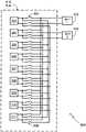
图3图示了包括九个并行功率级和两个充电器端口的充电器;Figure 3 illustrates a charger comprising nine parallel power stages and two charger ports;
图4以图形图示了图3所示的充电器的示例性使用情形;Figure 4 graphically illustrates an exemplary usage scenario for the charger shown in Figure 3;
图5图示了用于随诸如图3所示充电器的充电器使用的具体接触器配置;Figure 5 illustrates a specific contactor configuration for use with a charger such as that shown in Figure 3;
图6图示了可替换的接触器配置;Figure 6 illustrates an alternative contactor configuration;
图7图示了另一种可替换的接触器配置;Figure 7 illustrates another alternative contactor configuration;
图8图示了另一种可替换的接触器配置;Figure 8 illustrates another alternative contactor configuration;
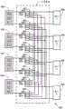
图9图示了图5所示的接触器配置,其被扩展以包括附加功率级和附加端口,其中接触器被打开/关闭以说明示例使用配置;和Figure 9 illustrates the contactor configuration shown in Figure 5 expanded to include additional power stages and additional ports, with the contactors being opened/closed to illustrate an example use configuration; and
图10图示了在向本发明的电池充电站的各个充电端口分配功率时所使用的基本方法。Figure 10 illustrates the basic method used in distributing power to the various charging ports of the battery charging station of the present invention.
具体实施方式Detailed ways
在下文中,术语“电池(battery)”、“电池(cell)”、“电池(batterycell)”可以互换使用并且可以指代任意的各种不同电池类型、化学成分和配置,其包括但并不局限于锂离子(例如锂离子磷酸盐、锂氧化钴、其它锂金属氧化物等)、锂离子聚合物、镍金属氢化物、镍镉、镍氢、镍锌、银锌或者其它电池类型/配置。术语“电池组”在这里被用来指代多个个体电池,它们典型地包含在单块或多块的外壳之内,该个体电池电气互连以实现特定应用所期望的电压和容量。术语“电池”和“电池系统”可以互换使用并且在这里被用来指代电能存储系统,其具有诸如电池、电池组、电容器或超级电容器之类的被充电和放电的能力。术语“电动车辆”在这里被用来指代也被称作EV的全电动车辆、也被称作PHEV的插电式混合动力车辆或者混合动力车辆(HEV),其中混合动力车辆采用其中之一为电驱动系统的多个推进源。应当理解的是,在多个附图上使用相同的附图标记来指代相同的组件或者等同功能的组件。此外,附图仅意在对本发明的范围进行说明而非限制并且不应当被认为是依比例绘制的。Hereinafter, the terms "battery," "cell," and "battery cell" are used interchangeably and may refer to any of a variety of different battery types, chemistries, and configurations, including, but not Limited to Li-ion (e.g. Li-ion phosphate, lithium cobalt oxide, other lithium metal oxides, etc.), Li-ion polymer, nickel metal hydride, nickel cadmium, nickel metal hydride, nickel zinc, silver zinc, or other battery types/configurations . The term "battery pack" is used herein to refer to a plurality of individual batteries, typically contained within a single or multi-piece housing, that are electrically interconnected to achieve the voltage and capacity desired for a particular application. The terms "battery" and "battery system" are used interchangeably and are used herein to refer to electrical energy storage systems that have the ability to be charged and discharged, such as batteries, batteries, capacitors, or supercapacitors. The term "electric vehicle" is used herein to refer to an all-electric vehicle, also known as an EV, a plug-in hybrid vehicle, also known as a PHEV, or a hybrid electric vehicle (HEV), where a hybrid vehicle employs either Multiple propulsion sources for electric drive systems. It should be understood that the use of the same reference numerals throughout the several figures indicates the same or functionally equivalent components. Furthermore, the drawings are only intended to illustrate rather than limit the scope of the invention and should not be considered to be drawn to scale.
本发明的实施例通常可应用于采用电动机的系统,更具体地而非排他性地,可应用于使用多相电动机(例如感应电动机)的电动车辆。电动车辆使用例如电池组之类的一个或多个存储能量源来向车辆提供电能。该能量至少部分被用来推进车辆。所存储的能量还可以被用来提供其它车辆系统所需的能量,例如车辆照明、乘客分区的加热、通风和空调(HVAC)系统、辅助控制系统(例如,传感器、显示器、导航系统等)、车辆娱乐系统(例如,无线电、DVD、MP3等)等。常规电动车辆包括载客车辆和被设计为运输货物的车辆,其示例包括乘用车、卡车、电动自行车和休闲船只。电动车辆还包括专用的工作车辆和推车,其中的一些可以整合有诸如叉车、剪刀式升降机、升降和/或曲臂空中作业平台、街道清洁系统、传送带和平板搬运平台。Embodiments of the invention are generally applicable to systems employing electric motors, and more particularly, but not exclusively, to electric vehicles employing multi-phase electric motors such as induction motors. Electric vehicles use one or more stored energy sources, such as a battery pack, to provide electrical energy to the vehicle. This energy is used at least in part to propel the vehicle. The stored energy can also be used to power other vehicle systems such as vehicle lighting, passenger zone heating, ventilation and air conditioning (HVAC) systems, auxiliary control systems (e.g., sensors, displays, navigation systems, etc.), Vehicle entertainment systems (eg, radio, DVD, MP3, etc.), etc. Conventional electric vehicles include passenger vehicles and vehicles designed to transport goods, examples of which include passenger cars, trucks, electric bicycles, and recreational watercraft. Electric vehicles also include specialized work vehicles and carts, some of which may incorporate features such as forklifts, scissor lifts, lift and/or articulating aerial work platforms, street cleaning systems, conveyor belts, and flatbed platforms.
图3图示了依据本发明的充电系统300的基本元件。这里还被称作充电站的充电器300耦合至例如电网的AC线路电压源301。充电器300包括多个并行功率级303-311,其中每一个包括AC至DC转换器。将要意识到的是,充电器300可以包括更少数量或更多数量的并行功率级,该数量取决于可从源301获得的功率、最大期望充电功率、所期望的充电灵活性水平以及充电端口的数量。在图3所示的示例性实施例中,充电器300包括一对充电端口313/314,但是依据本发明的充电器能够使用多于两个的充电端口,因此允许同时对多于两部的车辆进行充电。Figure 3 illustrates the basic elements of a
在本发明的至少一个优选实施例中并且如图3所示,并行功率级被一起分组为三组。因此在该实施例中功率级303-305被一起分组为功率模块315;功率级306-308被一起分组为功率模块316;并且功率级309-311被一起分组为功率模块317。分组为三个模块有助于确保三相位AC侧保持平衡。如果允许不平衡,则功率级无需被分组在一起,因此允许功率分配为更小的离散功率步长。In at least one preferred embodiment of the invention and as shown in Figure 3, the parallel power stages are grouped together into three groups. Thus in this embodiment power stages 303-305 are grouped together as
来自每个功率模块315-317的输出经由开关系统319而耦合至充电器端口313/314。开关系统319包括多个接触器或半导体开关或者其它开关器件,其允许来自每个功率模块的输出被电连接至任一充电器端口。优选地,开关系统319或对开关系统319进行操作的控制系统并不允许例如端口313的一个充电端口耦合至例如端口314的另一个充电端口。使用开关系统319,经由充电器端口耦合至特定车辆的功率量可以根据车辆需求、充电器端口使用、车辆充电优先级、费用等进行定制。耦合至开关系统319的控制器321通过应用存储器323中所记录的预定义分配规则集合而确定从功率模块到充电器端口的功率分配。在至少一个实施例中,控制器321是基于处理器的控制系统(例如微处理器)而存储器323是闪存、固态磁盘驱动器、硬盘驱动器或其它存储器类型或者存储器类型的组合。系统监视器325也耦合至控制器321,其对包括车辆/端口状态在内的充电系统进行连续监视。具体地,系统监视器325对端口313/314进行连续监视以便确定车辆何时耦合至充电系统。优选地,系统监视器325还通过端口获取车辆信息,但是这样的信息也可以经由其它手段(例如,无线网络、诸如RFID标签的车辆ID等)来获得。优选地,通过这些手段所获得的车辆信息将包括车辆电池容量、当前充电状态(SOC)、所期望SOC、电池充电容量、电池温度等。优选地,系统监视器325还耦合至如所示出的功率级或功率模块以便获得每个级和/或模块的功率输出/容量,对级/模块内的变化输出状态或问题的监视。在至少一个实施例中,系统监视器325还监视输入线路以便检测线路问题。系统监视器325还可以包括或耦合到确定充电费用的子系统327。充电费用可以基于每日时间、源301所提供的功率成本或者基于其它条件而变化。优选地,系统监视器325还包括一个或多个子系统329,其用于从最终用户接受金钱,并且在至少一些情况下用于确定最终用户所输入的金额。例如子系统329能够给从最终用户接受现金并且确定输入了多少金额。子系统329还能够接受信用卡或借记卡或者其它形式的非现金支付。优选地,系统监视器325还包括子系统331,其用于更新充电器300的分配指令或其它方面。子系统331可以包括无线或有线互联网连接。子系统331还可以利用不同通信系统/协议来获得系统更新。Outputs from each power module 315 - 317 are coupled to
在如图3所示的具有三个功率模块的充电器中,并且假设每个功率模块被配置为输出相同数量的功率,则能够以四个不同水平来分配功率:0输出、1/3Pmax、2/3Pmax和Pmax,其中Pmax等于来自充电器300的最大可用功率,即所有三个功率模块都耦合至单个端口。作为这种设计的结果并且如以上所提到的,控制器321能够根据控制器系统用来确定功率分配的标准而以各种不同比率将可用功率分配至耦合到充电器端口的车辆。In a charger with three power modules as shown in Figure 3, and assuming each power module is configured to output the same amount of power, power can be distributed at four different levels: 0 output, 1/3Pmax , 2/3Pmax and Pmax , where Pmax is equal to the maximum available power from the
图4以图形图示了充电器300的可能使用情形。该情形仅意在说明依据本发明所设计的充电系统可以如何被用来向两个车辆“A”和“B”分配功率而非对其进行限制。提供至车辆A和B的充电功率分别由曲线401和403所表示。在该示例中,假设最初在时间t0仅车辆A例如经由充电端口313耦合至充电器300。这样,控制器321最初将整个输出Pmax耦合至端口313。这由曲线401的第一部分所示出。随后,在时间t1,车辆B耦合至充电端口314。在该示例中,从时间t1到时间t2,车辆B没有从端口314接收到充电功率。这可能是因为给予车辆A的优先级或者出于其它一些原因。在时间t2,可从充电器300获得的功率在车辆A和B之间进行划分,其中车辆A降至2/3Pmax而车辆B则接收1/3Pmax。在时间t3,来自充电器300的功率对车辆A和B的划分被反转,其中车辆A现在接收1/3Pmax而车辆B现在接收2/3Pmax。该反转可能是由于车辆A减少了其对充电功率的要求。可替换地,并且如以下详细讨论的,控制器321可以使用一些其它标准来改变来自充电器300的功率对于两部车辆的分配。在时间t4,所有功率即Pmax被发送至车辆B。这例如可能是因为车辆A由于车辆A内的电池被完全充电而从充电器300脱离耦合。FIG. 4 graphically illustrates possible usage scenarios for the
图5-7图示了用于在诸如充电器300的充电器中使用的开关系统319的三种不同配置。如之前所提到的,本发明并不局限于仅九个并行功率级,也并不局限于仅使用两个端口。由此,系统500-700仅意在说明可以被用来向经由端口313/314耦合至充电器的一部或多部车辆提供充电功率的灵活分配的一些开关配置。5-7 illustrate three different configurations of switching
在系统500中,多个接触器501-512或者其它开关器件(例如,半导体开关)被用来控制从充电模块315-317到端口313/314的功率分配。在使用中,控制器321(该图中未示出)基于预设即预定义的分配指令集合而确定哪些功率模块要被耦合至哪些端口。如以下详细讨论的,这里也被称作分配规则的各种分配指令被用来确定有多少可用功率要被提供至每个充电器端口。将要意识到的是,系统500的12个接触器的配置可以被用来向端口313/314提供输出功率的任意组合。例如,通过关闭接触器501、503、506、508、510和512,功率模块315被耦合至端口313(因此向端口313提供1/3Pmax),并且功率模块316和317耦合至端口314(因此向端口314提供2/3Pmax)。In system 500, a plurality of contactors 501-512 or other switching devices (eg, semiconductor switches) are used to control power distribution from charging modules 315-317 to
在系统600中所示出的可替换接触器中,每个功率模块315-317使用一对三位置接触器(即,接触器601-606)来确定功率被耦合至端口313、端口314还是不耦合至任一端口。在系统600中,为了实现之前所描述的功率分配(即,对端口313的1/3Pmax以及对端口314的2/3Pmax),要求接触器601/602耦合至端口313(即,通过接触“A”触头)而接触器603-606则被耦合至端口314(即,通过接触“B”触头)。In the alternative contactors shown in
在系统700中所示的可替换接触器配置中,功率模块315-317使用八个接触器701-708被可控地耦合至端口313/314。虽然这种方法提供了简单的开关系统,但是其自身并不适用于具有多于两个端口的充电器。为了实现之前所描述的功率分配(即,对端口313的1/3Pmax以及对端口314的2/3Pmax),要求接触器701、702和705-708闭合而接触器703/704保持断开。In the alternate contactor configuration shown in
如之前所提到的,虽然优选将功率级叠加为三个分组而使得三相AC侧保持平衡,但是如果不要求平衡,则本发明可同样被应用于非叠加配置。虽然任意的开关系统可以利用非叠加功率级进行配置,但是该方法通过修改系统500中所示的配置而在图8中进行图示。在系统800中,与每个模块使用两对双位置接触器相反,每个功率级使用两对双位置接触器。结果,对于相同数量的功率级以及相同的双端口配置而言,接触器的数量从系统500所示的12个接触器(即接触器501-512)增加为系统800所示的36个接触器(即接触器801-836)(注意,虽然所有36个接触器都在图8中示出,但是为了使得示图更具可读性仅标记了接触器801和836)。因此,虽然系统800所图示的方式提供了更大的功率分配灵活性,但是发明人已经发现该额外的灵活性与额外的开关复杂度和相关成本相比通常并不值得。As previously mentioned, while it is preferable to stack the power stages into three groups so that the three-phase AC side remains balanced, if balancing is not required, the invention can equally be applied to non-stacked configurations. While any switching system can be configured with non-superimposed power stages, the method is illustrated in FIG. 8 by modifying the configuration shown in system 500 . In
虽然已经使用仅三个功率模块和两个车辆端口对本发明进行了阐述,但是本发明在功率模块和车辆端口方面可轻易进行扩展。例如,图9所示的系统900基于图5所示的基本配置,其被修改为包括4个功率模块901-904以及四个端口905-908。如所示出的,优选地每个功率模块901-904都由三个功率级(即,级909-920)所组成,这是为了同时实现三相AC侧上的平衡以及利用最小的开关系统复杂度提供所期望的功率水平。注意到,在所图示的实施例中,接触器921和925被示为闭合以便向端口905提供1/4Pmax;接触器930和934被示为闭合以便向端口906提供1/4Pmax;并且接触器940、944、948和952被示为闭合以便向端口908提供1/2Pmax。如所示出的,当前没有功率被耦合至端口907。Although the invention has been explained using only three power modules and two vehicle ports, the invention is easily expandable in terms of power modules and vehicle ports. For example, the
耦合至该开关系统的控制器在确定如何向耦合至充电器端口的车辆分配可从功率模块或功率级获得的功率时可以使用各种标准。图10图示了控制器(例如,控制器321)在向各个端口分配功率时所应用的基本方法。通常,充电器控制器连续监视系统(例如,充电系统、充电端口和/或附接至充电端口的车辆)以便检测影响充电器的变化(步骤1001)。无论系统何时检测到可能会影响功率分配的变化(步骤1003),控制器就基于预定义分配指令集合和当前所监视的状态来确定适当分配功率(步骤1005)。常见的影响功率分配的变化包括但并不局限于车辆经由充电器端口之一耦合至充电器或与之断开耦合或者改变要应用于耦合至充电器的一部或多部车辆的充电要求。影响功率分配的较不常见的变化示例包括(i)经过时间,例如在分配指令包括时间要求的情况下;(ii)所要充电的车辆之一的状态变化,例如在充电周期开始时所支付的费用已经用尽的情况;和/或(iii)电池温度或其他车辆状态出现的不期望的变化。A controller coupled to the switching system may use various criteria in determining how to distribute the power available from the power module or power stage to the vehicle coupled to the charger port. FIG. 10 illustrates the basic method applied by a controller (eg, controller 321 ) in allocating power to various ports. Typically, the charger controller continuously monitors the system (eg, charging system, charging port, and/or vehicle attached to the charging port) to detect changes affecting the charger (step 1001 ). Whenever the system detects a change that may affect power allocation (step 1003), the controller determines the appropriate allocation of power based on the set of predefined allocation instructions and the current monitored status (step 1005). Common changes affecting power distribution include, but are not limited to, coupling or uncoupling of a vehicle to or from a charger via one of the charger ports or changing the charging requirements to be applied to one or more vehicles coupled to the charger. Examples of less common changes affecting power allocation include (i) elapsed time, such as where the allocation order includes a time requirement; (ii) a change in the state of one of the vehicles to be charged, such as the amount paid at the beginning of a charging cycle. the charge has been exhausted; and/or (iii) an undesired change in battery temperature or other vehicle state.
将要意识到的是,本发明的充电系统可以经由预定义分配指令进行配置而基于各种状态向耦合至充电系统的各车辆分配功率,并且本发明并不局限于以下所描述的示例性分配指令。可以被本发明控制器用来从充电器的功率级/功率模块向接合至充电器的车辆分配功率的示例性功率分配指令包括:It will be appreciated that the charging system of the present invention can be configured via predefined distribution instructions to distribute power to various vehicles coupled to the charging system based on various states, and that the invention is not limited to the exemplary distribution instructions described below . Exemplary power distribution commands that may be used by the controller of the present invention to distribute power from the charger's power stage/power module to the vehicle coupled to the charger include:
到达时间优先级:在功率分配基于到达时间的充电器中,系统监视经由其端口之一耦合至充电器的每部车辆的到达时间,并且基于所监视的到达时间授予优先级。优先车辆被提供以最大量的可用功率,其限制仅在于车辆电池的需求。因此,例如,在依据本发明的该实施例所设计并进行操作的多端口充电器中,耦合至充电器的第一车辆被给予最大可用功率。假设第一车辆要求最大可用功率,则在第一车辆之后耦合至充电器的车辆将不会接收到充电功率。然后,随着第一车辆的需求逐渐减小并且功率变为可用,耦合至充电器的第二车辆被提供以剩余功率。当第一车辆的电池完全充电或者被充电至预设SOC时,在假设第二车辆能够使用最大可用功率的情况下,向第二车辆提供最大可用功率。在优先级基于到达充电器的时间的情况下,这种向优先车辆提供最大可用功率的过程针对耦合至充电器的每部车辆继续进行。作为这种方法的结果,第一部耦合至充电器的车辆是第一部进行充电的车辆,第二部耦合至充电器的车辆是第二部进行充电的车辆,等等。Time of Arrival Priority : In a time of arrival based charger, the system monitors the time of arrival of each vehicle coupled to the charger via one of its ports and grants priority based on the monitored time of arrival. Priority vehicles are provided with the maximum amount of available power, limited only by the needs of the vehicle's batteries. Thus, for example, in a multi-port charger designed and operative in accordance with this embodiment of the invention, the first vehicle coupled to the charger is given the maximum available power. Assuming the first vehicle requires the maximum available power, vehicles coupled to the charger after the first vehicle will not receive charging power. Then, as the first vehicle's demand tapers off and power becomes available, a second vehicle coupled to the charger is provided with the remaining power. When the battery of the first vehicle is fully charged or is charged to a preset SOC, the maximum available power is provided to the second vehicle assuming that the second vehicle is able to use the maximum available power. Where priority is based on time of arrival at the charger, this process of providing the maximum available power to the priority vehicle continues for each vehicle coupled to the charger. As a result of this approach, the first vehicle coupled to the charger is the first vehicle being charged, the second vehicle coupled to the charger is the second vehicle being charged, and so on.
基于费用的优先级:在可替换实施例中,基于最终用户所支付的费用即充电器使用费而给予优先级,因此允许用户通过为使用充电器支付更多费用来获得充电优先级。在一种情况下,无论用户的车辆需要多少功率,充电器都从用户接收每次充电过程的一次性优先费用。在可替换情况下,优先顾客为充电期间所使用的每千瓦功率(或其它量度)支付更高费用。将要意识到的是,基于费用的优先级系统可以应用简单的两层成本费用结构或者采用多层成本费用结构,后者更适用于包括多于两个充电器端口的充电器。通常,使用基于费用的优先级方案分配充电功率的充电器使用另一种优先级方案,例如以上所描述的基于到达时间的优先级方案,而用户能够通过支付优先费用而绕过该优先级方案。实际上,该方案允许用户通过支付更多而跳过其他用户。注意到,如果两个或更多用户支付了优先费用,假设他们支付了相同的优先费用,则优选地该充电系统依赖于基本优先级方案。因此,例如在具有三个或更多端口的充电器中,如果基本优先级方案是基于到达时间的优先级方案并且第一部车辆支付了基本费率而耦合至充电器的第二部和第三部车辆支付了相同的优先级费费用,则即使他们支付了相同的优先费用,第二部车辆也将被给予高于第三部车辆的优先级。显然,这种方法的修改和变化被发明人所预期。Fee-Based Priority : In an alternative embodiment, priority is given based on the fee paid by the end user, charger usage, thus allowing the user to get charging priority by paying more to use the charger. In one instance, the charger receives a one-time priority fee from the user for each charging session, regardless of how much power the user's vehicle requires. In the alternative, preferred customers pay a higher fee per kilowatt of power (or other measure) used during charging. It will be appreciated that a fee-based prioritization system can employ a simple two-tier cost structure or employ a multi-tier cost structure, the latter being more suitable for chargers that include more than two charger ports. Typically, chargers that use a fee-based priority scheme to allocate charging power use another priority scheme, such as the time-of-arrival priority scheme described above, that the user can bypass by paying a priority fee . In effect, the scheme allows users to skip other users by paying more. Note that if two or more users pay priority charges, it is preferred that the charging system relies on the basic priority scheme, assuming they pay the same priority charge. So, for example, in a charger with three or more ports, if the basic priority scheme is a time-of-arrival based priority scheme and the first vehicle pays the basic rate and the second and second vehicles coupled to the charger Three vehicles have paid the same priority fee, the second vehicle will be given priority over the third even though they have paid the same priority fee. Obviously, modifications and variations of this method are contemplated by the inventor.
优先顾客:在可替换实施例中,某些车辆被自动给予高于其它车辆的优先级。例如,优先级可以基于特定车辆厂商(即,制造商)或模型。可替换地,优先级可以被给予属于例如美国汽车协会即AAA的特定俱乐部或协会的充电器顾客。可替换地,可以为使用某种支付形式(例如,相对于信用卡的现金)或特定信用卡(例如,相对于

预约:在可替换实施例中,用户能够预约充电器端口,例如针对具体时间和日期在具体充电站进行预约。优选地,充电器包括能够用来向潜在用户通知端口不可用的显示器或其它器件。在至少一个优选实施例中,控制器在预约时间或预约时间之前使得最后一个剩余的可用端口无效,并且例如在充电系统显示器上显示该最后的剩余端口已经被预约的通知消息。该通知显示允许开车赶到的用户快速确认该端口无法供其使用。预约端口的通知例如也可以在充电站运营商所维护的网页上进行发布。优选地,用户能够使用互联网基于Web的系统针对具体日期和时间预约具体充电器上的端口。通常,兴趣方例如使用基于web的充电器位置服务首先定位所期望位置处的充电站,并且随后使用运营所选择充电器的公司或第三方服务提供商所提供的服务(例如,基于web的服务)来预约端口。Reservation : In an alternative embodiment, the user is able to reserve a charger port, eg at a specific charging station for a specific time and date. Preferably, the charger includes a display or other device that can be used to notify a potential user that the port is unavailable. In at least one preferred embodiment, the controller invalidates the last remaining available port at or before the reserved time, and displays a notification message that the last remaining port has been reserved, eg, on a display of the charging system. The notification display allows users who arrive by car to quickly confirm that the port is not available for their use. The notification of the port reservation may also be published, for example, on a web page maintained by the charging station operator. Preferably, the user is able to reserve a port on a particular charger for a particular date and time using an Internet web-based system. Typically, an interested party first locates a charging station at a desired location, such as using a web-based charger location service, and then uses a service provided by the company operating the selected charger or a third-party service provider (e.g., a web-based service). ) to reserve the port.
预约功率分布:在之前所描述的基于预约的优先级系统的小幅修改形式中,预约方还能够预约具体的充电分布(profile)。例如,最终用户可能希望不仅预约充电器端口而且还预约对其车辆进行快速充电的功能。可替换地,最终用户可能希望确保特定充电站可以使用,该充电站例如其家、酒店、公司等附近的站点,但是同时认识到其车辆将在该位置停留很长一段时间周期,例如整夜。在这种情况下,用户仅需要预约充电器端口而无需预约以加快速率进行充电的功能。Subscriber Power Profiles : In a slightly modified form of the previously described subscription-based priority system, subscribers are also able to subscribe to specific charging profiles. For example, an end user may wish to subscribe not only to a charger port but also the ability to fast charge their vehicle. Alternatively, an end user may wish to ensure that a particular charging station is available, such as a site near their home, hotel, business, etc., but at the same time realize that their vehicle will be at that location for an extended period of time, such as overnight . In this case, the user only needs to reserve the charger port and not the function of charging at an accelerated rate.
基于车辆需求的功率分配:在可替换实施例中,充电器控制器在车辆耦合至充电站时例如通过确认该车辆的SOC和充电容量来确定每部车辆的需求。在确定功率分布时还可以使用每部车辆的电池组的温度。优选地,该信息由所耦合的车辆使用协商的通信协议而提供给充电器控制器。使用该信息,控制器向耦合至充电器的车辆分配功率,例如基于需求,或者基于尽可能快地使得所有耦合车辆达到预定最低SOC水平,或者基于使得所有耦合车辆达到表示该车辆的总电池容量的预定百分比的SOC水平来分配可用充电功率。Power Allocation Based on Vehicle Demand : In an alternative embodiment, the charger controller determines each vehicle's demand when the vehicle is coupled to the charging station, eg, by ascertaining the vehicle's SOC and charging capacity. The temperature of each vehicle's battery pack may also be used in determining the power profile. Preferably, this information is provided to the charger controller by the coupled vehicle using a negotiated communication protocol. Using this information, the controller allocates power to vehicles coupled to the charger, for example based on demand, or based on bringing all coupled vehicles to a predetermined minimum SOC level as quickly as possible, or based on bringing all coupled vehicles to a total battery capacity representative of the vehicle A predetermined percentage of the SOC level is used to allocate the available charging power.
基于用户需求的功率分配:在可替换实施例中,当用户将其车辆耦合至充电系统时,它们向控制器输入可以在确定最优功率分配时使用的信息。例如,用户可以输入其预期离开时间,因此允许控制器确定有多少时间可用于对该特定车辆进行电池充电。当车辆耦合至具有不同离开时间的充电器时,例如一部车辆有两小时进行充电而另一部车辆可能有十二小时来充电,则控制器能够对可用功率的使用进行优化。优选地,如果没有输入或收集到可被充电器控制器用来优化功率分配的信息,则系统依赖于缺省数据集合。Power allocation based on user needs : In an alternative embodiment, when users couple their vehicles to the charging system, they input information to the controller that can be used in determining optimal power allocation. For example, a user may enter their expected departure time, thus allowing the controller to determine how much time is available for battery charging for that particular vehicle. When vehicles are coupled to chargers with different departure times, for example one vehicle has two hours to charge and another vehicle may have twelve hours to charge, the controller can optimize the use of available power. Preferably, the system relies on a default data set if no information is entered or collected that can be used by the charger controller to optimize power distribution.
基于最大充电器输出的功率分配:在可替换实施例中,不同于例如基于到达时间、费用、车辆优先级等向特定车辆或顾客给予优先级,控制器使得充电器输出最大化。车辆优先级仅被作为次要考虑因素。例如,假设充电系统具有如图3和5-7所示的三个功率模块并且其中每个模块具有30kW的输出,并且假设耦合至端口313和314的车辆分别请求35kW和50kW,并且耦合至端口313的车辆具有比其它车辆更高的优先级(例如,由于到达时间或其它原因),如果充电系统在这种模式下进行操作,则控制器将会把一个功率模块耦合至端口313并且将两个功率模块耦合至端口314,因此使用可用的90kW中的80kW。在诸如之前所描述的功率分配基于优先级而非使得充电器输出最大化的那些可替换配置中,两个功率模块将会被耦合至与端口313耦合的较高优先级的车辆以便为该车辆提供以所请求的35kW。结果,该可替换配置将仅使用可用的90kW中的65kW。注意到,在当前所描述的以及如以上所提到的配置中,如果充电器的最大输出在若干分配方案下相同,则优选地使用次要考虑因素(诸如到达时间优先级)来确定适当功率分配。例如,在之前的说明中,如果两部车辆都要求35kW,则控制器将会把两个功率模块耦合至与端口313耦合的车辆,因为该车辆具有更高优先级而且反转该分配且将两个功率模块耦合至端口314将不会产生更高的充电器输出。Power allocation based on maximum charger output : In an alternative embodiment, instead of giving priority to specific vehicles or customers based on eg arrival time, cost, vehicle priority, etc., the controller maximizes charger output. Vehicle priority is only considered a secondary consideration. For example, assume that the charging system has three power modules as shown in Figures 3 and 5-7 and each of these modules has an output of 30kW, and assume that the vehicles coupled to
如之前所提到的,本发明的充电器控制器应用预定义的功率分配规则集合以便确定由于功率级/模块的使用而在离散步骤中可用的充电功率如何在耦合至充电器的充电器端口的车辆之间进行分配。虽然已经对可以单独或相结合应用的各种功率分配规则进行了描述,但是将要意识到的是,本发明并不局限于功率分配规则的特定集合并且这里所提供的意在使得本发明的应用清楚而非对其进行限制。此外,应当理解的是,即使在车辆为耦合至本发明的多端口充电器的仅有车辆的情况下,预定义的功率分配规则集合也可能对应用于该车辆的充电功率加以限制。例如,如果分配规则仅在支付优先费用时才提供最大充电功率或者如果所涉及车辆/用户为优先车辆/用户,则可能会出现这种结果。As previously mentioned, the charger controller of the present invention applies a predefined set of power distribution rules in order to determine how the charging power available in discrete steps due to the use of power stages/modules is distributed among the charger ports coupled to the charger. distribution among the vehicles. While various power allocation rules have been described which may be applied individually or in combination, it will be appreciated that the present invention is not limited to a particular set of power allocation rules and that what is provided herein is intended to enable application of the present invention clear rather than restrictive. Furthermore, it should be understood that even where a vehicle is the only vehicle coupled to the multi-port charger of the present invention, the predefined set of power distribution rules may place limits on the charging power applied to that vehicle. This result may arise, for example, if the allocation rules provide maximum charging power only when the priority fee is paid or if the vehicle/user in question is a priority vehicle/user.
已经在总体上将系统和方法描述为有助于理解本发明的细节。此外,已经给出了各种具体细节以提供本发明实施例的总体理解。然而,相关领域的技术人员将会认识到,本发明的实施例可以在没有一个或多个具体细节的情况下进行实践,或者利用其它装置、系统、配件、方法、组件、材料、部分等进行实践。在其它情况下,并未特别示出或详细描述公知结构、材料和/或操作以避免对本发明实施例的各方面造成混淆。Systems and methods have generally been described in detail to facilitate an understanding of the invention. Additionally, various specific details have been given to provide a general understanding of embodiments of the invention. However, one skilled in the relevant art will recognize that the embodiments of the invention may be practiced without one or more of the specific details, or with other devices, systems, assemblies, methods, components, materials, sections, etc. practice. In other instances, well-known structures, materials, and/or operations are not specifically shown or described in detail to avoid obscuring aspects of the embodiments of the invention.
因此,虽然在此已经参考其特定实施例对本发明进行了描述,但是将要意识到的是,本发明可以以其它具体形式来实现,例如针对特定情形或材料或组件进行调适,而并不背离其精神或必要特征。因此,这里的公开和描述意在作为以下权利要求中所给出的本发明范围的说明而非限制。Thus, although the invention has been described herein with reference to specific embodiments thereof, it will be appreciated that the invention may be embodied in other specific forms, for example adapted to a particular situation or materials or components, without departing from its Spiritual or essential characteristics. Accordingly, the disclosure and description herein are intended as illustrations and not as limitations of the scope of the invention, which is set forth in the following claims.
Claims (46)
Translated fromChinesePriority Applications (1)
| Application Number | Priority Date | Filing Date | Title |
|---|---|---|---|
| CN201710091149.9ACN107026487B (en) | 2011-09-02 | 2012-06-05 | Multiport vehicle DC charging system with variable power distribution |
Applications Claiming Priority (5)
| Application Number | Priority Date | Filing Date | Title |
|---|---|---|---|
| US13/224,506US8643330B2 (en) | 2011-09-02 | 2011-09-02 | Method of operating a multiport vehicle charging system |
| US13/224,506 | 2011-09-02 | ||
| US13/224,368 | 2011-09-02 | ||
| US13/224,368US8810198B2 (en) | 2011-09-02 | 2011-09-02 | Multiport vehicle DC charging system with variable power distribution according to power distribution rules |
| PCT/US2012/000271WO2013032519A1 (en) | 2011-09-02 | 2012-06-05 | Multiport vehicle dc charging system with variable power distribution |
Related Child Applications (1)
| Application Number | Title | Priority Date | Filing Date |
|---|---|---|---|
| CN201710091149.9ADivisionCN107026487B (en) | 2011-09-02 | 2012-06-05 | Multiport vehicle DC charging system with variable power distribution |
Publications (2)
| Publication Number | Publication Date |
|---|---|
| CN103828181Atrue CN103828181A (en) | 2014-05-28 |
| CN103828181B CN103828181B (en) | 2017-04-05 |
Family
ID=47752629
Family Applications (2)
| Application Number | Title | Priority Date | Filing Date |
|---|---|---|---|
| CN201710091149.9AActiveCN107026487B (en) | 2011-09-02 | 2012-06-05 | Multiport vehicle DC charging system with variable power distribution |
| CN201280041847.3AActiveCN103828181B (en) | 2011-09-02 | 2012-06-05 | Multiport Vehicle DC Charging System with Variable Power Distribution |
Family Applications Before (1)
| Application Number | Title | Priority Date | Filing Date |
|---|---|---|---|
| CN201710091149.9AActiveCN107026487B (en) | 2011-09-02 | 2012-06-05 | Multiport vehicle DC charging system with variable power distribution |
Country Status (5)
| Country | Link |
|---|---|
| US (2) | US8810198B2 (en) |
| EP (1) | EP2751902B1 (en) |
| JP (1) | JP2014527393A (en) |
| CN (2) | CN107026487B (en) |
| WO (1) | WO2013032519A1 (en) |
Cited By (43)
| Publication number | Priority date | Publication date | Assignee | Title |
|---|---|---|---|---|
| CN104079052A (en)* | 2014-07-04 | 2014-10-01 | 国家电网公司 | Direct-current charging system of electric automobile |
| CN104539030A (en)* | 2014-12-09 | 2015-04-22 | 许继电气股份有限公司 | Direct-current fast double-charging system and control method with power dynamically distributed |
| CN104578273A (en)* | 2014-12-23 | 2015-04-29 | 深圳市科陆电子科技股份有限公司 | Electric energy dispatching charging system and method |
| CN104600779A (en)* | 2014-12-18 | 2015-05-06 | 深圳市科陆电子科技股份有限公司 | Charging system |
| CN104701948A (en)* | 2015-03-30 | 2015-06-10 | 北京中科盛康科技有限公司 | Charger for battery pack |
| CN105024433A (en)* | 2015-09-01 | 2015-11-04 | 深圳市科华恒盛科技有限公司 | Charge power distribution system and method for dual-path charging |
| CN105186650A (en)* | 2015-10-10 | 2015-12-23 | 愈先梅 | Direct current charging pile system for electric automobile |
| CN105226752A (en)* | 2015-10-10 | 2016-01-06 | 愈先梅 | Electric automobile direct-current charging post system |
| CN105244945A (en)* | 2015-10-10 | 2016-01-13 | 愈先梅 | DC charging pole system of electromobile |
| CN105375599A (en)* | 2015-10-10 | 2016-03-02 | 愈先梅 | Electric automobile direct-current charging pile system |
| CN105375554A (en)* | 2015-10-10 | 2016-03-02 | 愈先梅 | Electric automobile direct-current charging pile system |
| CN106114271A (en)* | 2016-08-18 | 2016-11-16 | 广东志成冠军集团有限公司 | An electric vehicle charging system |
| CN106816901A (en)* | 2015-11-30 | 2017-06-09 | 比亚迪股份有限公司 | Electri forklift charger |
| CN106882062A (en)* | 2017-01-20 | 2017-06-23 | 深圳市丁旺科技有限公司 | It is a kind of can smooth expansion direct-current charging post implementation method |
| CN107565711A (en)* | 2017-09-13 | 2018-01-09 | 深圳先进技术研究院 | Wireless charging power distribution method, device, equipment and storage medium |
| CN107572005A (en)* | 2017-10-16 | 2018-01-12 | 四川航电微能源有限公司 | The multifunctional combined electric power system in airport |
| CN108068650A (en)* | 2016-11-16 | 2018-05-25 | 保时捷股份公司 | general current charger |
| CN108242828A (en)* | 2016-12-27 | 2018-07-03 | 飞宏科技股份有限公司 | Intelligent power distribution system for charging pile |
| CN109165822A (en)* | 2018-08-06 | 2019-01-08 | 上海顺舟智能科技股份有限公司 | A kind of energy recharge management system and management method |
| CN109256828A (en)* | 2017-07-14 | 2019-01-22 | 德尔格制造股份两合公司 | Can cascade multiple charger and operation can cascade multiple charger method |
| CN109478796A (en)* | 2016-05-12 | 2019-03-15 | 力特有限公司 | Relays for use with multiple power supplies |
| WO2019061987A1 (en)* | 2017-09-30 | 2019-04-04 | 安克创新科技股份有限公司 | Charging device and charging method thereof |
| CN109591650A (en)* | 2018-11-20 | 2019-04-09 | 恒大智慧科技(深圳)有限公司 | Charge power dynamic regulation method, computer equipment and storage medium |
| CN109677295A (en)* | 2019-01-15 | 2019-04-26 | 山东电工电气集团新能科技有限公司 | One machine multiple gun power automatic distributing system of direct-current charging post |
| CN109808531A (en)* | 2017-11-20 | 2019-05-28 | 奥迪股份公司 | For giving the method and charging pile of multiple electric vehicle chargings |
| CN110014936A (en)* | 2017-07-20 | 2019-07-16 | 通用汽车环球科技运作有限责任公司 | Charging system for autonomous vehicle |
| CN110014905A (en)* | 2017-08-07 | 2019-07-16 | 现代自动车株式会社 | Wireless charging control method and the power supply unit for using this method |
| CN110435473A (en)* | 2019-08-16 | 2019-11-12 | 山东山大电力技术股份有限公司 | A kind of power switching device, team control charging system and method |
| CN110718953A (en)* | 2019-11-11 | 2020-01-21 | 广州极飞科技有限公司 | Charging circuit and charging system |
| CN110999007A (en)* | 2017-06-23 | 2020-04-10 | 奥迪股份公司 | Electrical energy supply device with a busbar array and method for operating the same |
| CN111009944A (en)* | 2019-12-24 | 2020-04-14 | 广州极飞科技有限公司 | Charging module and charging system |
| CN111301194A (en)* | 2020-02-27 | 2020-06-19 | 北京海博思创科技有限公司 | Movable charging station and movable platform |
| CN112277714A (en)* | 2020-09-18 | 2021-01-29 | 国网浙江省电力有限公司杭州供电公司 | Charging pile allocation method and device based on profit of electric vehicle charging station |
| CN112671062A (en)* | 2020-12-17 | 2021-04-16 | 维沃移动通信有限公司 | Charging control method and device |
| CN112810472A (en)* | 2019-11-15 | 2021-05-18 | 中车株洲电力机车研究所有限公司 | Vehicle-mounted charging system |
| CN112970167A (en)* | 2018-10-26 | 2021-06-15 | 雷诺股份公司 | Method for charging a battery by means of a charging station |
| CN113381471A (en)* | 2021-05-26 | 2021-09-10 | 深圳市德兰明海科技有限公司 | Control method and device for output limit value of charger and battery energy storage system |
| CN113696734A (en)* | 2021-07-31 | 2021-11-26 | 重庆长安新能源汽车科技有限公司 | High-voltage system energy priority arbitration and distribution method, computer storage medium and automobile |
| CN114599545A (en)* | 2019-10-22 | 2022-06-07 | Abb瑞士股份有限公司 | Electric vehicle charging system for preventing simultaneous closing of socket contactors |
| CN115398767A (en)* | 2020-04-06 | 2022-11-25 | 三菱电机株式会社 | Charging power management device and charging power management method |
| CN115649009A (en)* | 2022-12-07 | 2023-01-31 | 小米汽车科技有限公司 | Charging method, charging device, vehicle, readable storage medium and chip |
| CN116394788A (en)* | 2023-02-13 | 2023-07-07 | 深圳市田科信息技术有限公司 | A power distribution system, method and charging pile based on multi-modal sensing |
| CN117601702A (en)* | 2023-11-08 | 2024-02-27 | 国网上海市电力公司 | DC charging device, DC charging method, and computer-readable storage medium |
Families Citing this family (351)
| Publication number | Priority date | Publication date | Assignee | Title |
|---|---|---|---|---|
| US8013570B2 (en) | 2009-07-23 | 2011-09-06 | Coulomb Technologies, Inc. | Electrical circuit sharing for electric vehicle charging stations |
| US9878629B2 (en) | 2009-12-17 | 2018-01-30 | Chargepoint, Inc. | Method and apparatus for electric vehicle charging station load management in a residence |
| KR101180956B1 (en)* | 2010-12-02 | 2012-09-07 | 기아자동차주식회사 | Antitheft system of charger for electric vehicle |
| DE102011008675A1 (en)* | 2011-01-15 | 2012-07-19 | Daimler Ag | Method for charging a battery of a vehicle |
| JP5874268B2 (en)* | 2011-09-22 | 2016-03-02 | 日産自動車株式会社 | Charging apparatus and charging method |
| KR101902795B1 (en)* | 2012-02-21 | 2018-11-14 | 삼성전자주식회사 | Method for wireless charging and apparatus for the same |
| JP5835023B2 (en)* | 2012-03-07 | 2015-12-24 | 株式会社デンソー | Charging point arrival determination system and vehicle side device |
| JP5835024B2 (en)* | 2012-03-07 | 2015-12-24 | 株式会社デンソー | Charging point notification system and vehicle side device |
| US8981718B2 (en)* | 2012-05-25 | 2015-03-17 | Nissan North America, Inc. | Serial multi-vehicle quick charge station |
| JP6179512B2 (en)* | 2012-07-04 | 2017-08-16 | 日本電気株式会社 | Charging system control device, charging system, program, and control method |
| US10381880B2 (en) | 2014-07-21 | 2019-08-13 | Energous Corporation | Integrated antenna structure arrays for wireless power transmission |
| US10211680B2 (en) | 2013-07-19 | 2019-02-19 | Energous Corporation | Method for 3 dimensional pocket-forming |
| US9887739B2 (en) | 2012-07-06 | 2018-02-06 | Energous Corporation | Systems and methods for wireless power transmission by comparing voltage levels associated with power waves transmitted by antennas of a plurality of antennas of a transmitter to determine appropriate phase adjustments for the power waves |
| US9847677B1 (en) | 2013-10-10 | 2017-12-19 | Energous Corporation | Wireless charging and powering of healthcare gadgets and sensors |
| US9939864B1 (en)* | 2014-08-21 | 2018-04-10 | Energous Corporation | System and method to control a wireless power transmission system by configuration of wireless power transmission control parameters |
| US10186913B2 (en) | 2012-07-06 | 2019-01-22 | Energous Corporation | System and methods for pocket-forming based on constructive and destructive interferences to power one or more wireless power receivers using a wireless power transmitter including a plurality of antennas |
| US9900057B2 (en) | 2012-07-06 | 2018-02-20 | Energous Corporation | Systems and methods for assigning groups of antenas of a wireless power transmitter to different wireless power receivers, and determining effective phases to use for wirelessly transmitting power using the assigned groups of antennas |
| US10211674B1 (en) | 2013-06-12 | 2019-02-19 | Energous Corporation | Wireless charging using selected reflectors |
| US10224982B1 (en) | 2013-07-11 | 2019-03-05 | Energous Corporation | Wireless power transmitters for transmitting wireless power and tracking whether wireless power receivers are within authorized locations |
| US10193396B1 (en) | 2014-05-07 | 2019-01-29 | Energous Corporation | Cluster management of transmitters in a wireless power transmission system |
| US9853692B1 (en) | 2014-05-23 | 2017-12-26 | Energous Corporation | Systems and methods for wireless power transmission |
| US10050462B1 (en) | 2013-08-06 | 2018-08-14 | Energous Corporation | Social power sharing for mobile devices based on pocket-forming |
| US10291055B1 (en) | 2014-12-29 | 2019-05-14 | Energous Corporation | Systems and methods for controlling far-field wireless power transmission based on battery power levels of a receiving device |
| US9787103B1 (en) | 2013-08-06 | 2017-10-10 | Energous Corporation | Systems and methods for wirelessly delivering power to electronic devices that are unable to communicate with a transmitter |
| US10256657B2 (en) | 2015-12-24 | 2019-04-09 | Energous Corporation | Antenna having coaxial structure for near field wireless power charging |
| US10263432B1 (en) | 2013-06-25 | 2019-04-16 | Energous Corporation | Multi-mode transmitter with an antenna array for delivering wireless power and providing Wi-Fi access |
| US10090886B1 (en) | 2014-07-14 | 2018-10-02 | Energous Corporation | System and method for enabling automatic charging schedules in a wireless power network to one or more devices |
| US11502551B2 (en) | 2012-07-06 | 2022-11-15 | Energous Corporation | Wirelessly charging multiple wireless-power receivers using different subsets of an antenna array to focus energy at different locations |
| US9973021B2 (en) | 2012-07-06 | 2018-05-15 | Energous Corporation | Receivers for wireless power transmission |
| US9876379B1 (en) | 2013-07-11 | 2018-01-23 | Energous Corporation | Wireless charging and powering of electronic devices in a vehicle |
| US9887584B1 (en) | 2014-08-21 | 2018-02-06 | Energous Corporation | Systems and methods for a configuration web service to provide configuration of a wireless power transmitter within a wireless power transmission system |
| US9843201B1 (en) | 2012-07-06 | 2017-12-12 | Energous Corporation | Wireless power transmitter that selects antenna sets for transmitting wireless power to a receiver based on location of the receiver, and methods of use thereof |
| US9824815B2 (en) | 2013-05-10 | 2017-11-21 | Energous Corporation | Wireless charging and powering of healthcare gadgets and sensors |
| US10312715B2 (en) | 2015-09-16 | 2019-06-04 | Energous Corporation | Systems and methods for wireless power charging |
| US9871398B1 (en) | 2013-07-01 | 2018-01-16 | Energous Corporation | Hybrid charging method for wireless power transmission based on pocket-forming |
| US10270261B2 (en) | 2015-09-16 | 2019-04-23 | Energous Corporation | Systems and methods of object detection in wireless power charging systems |
| US9847679B2 (en) | 2014-05-07 | 2017-12-19 | Energous Corporation | System and method for controlling communication between wireless power transmitter managers |
| US9882430B1 (en) | 2014-05-07 | 2018-01-30 | Energous Corporation | Cluster management of transmitters in a wireless power transmission system |
| US10230266B1 (en) | 2014-02-06 | 2019-03-12 | Energous Corporation | Wireless power receivers that communicate status data indicating wireless power transmission effectiveness with a transmitter using a built-in communications component of a mobile device, and methods of use thereof |
| US10223717B1 (en) | 2014-05-23 | 2019-03-05 | Energous Corporation | Systems and methods for payment-based authorization of wireless power transmission service |
| US9876394B1 (en) | 2014-05-07 | 2018-01-23 | Energous Corporation | Boost-charger-boost system for enhanced power delivery |
| US9893554B2 (en) | 2014-07-14 | 2018-02-13 | Energous Corporation | System and method for providing health safety in a wireless power transmission system |
| US10211682B2 (en) | 2014-05-07 | 2019-02-19 | Energous Corporation | Systems and methods for controlling operation of a transmitter of a wireless power network based on user instructions received from an authenticated computing device powered or charged by a receiver of the wireless power network |
| US9941707B1 (en) | 2013-07-19 | 2018-04-10 | Energous Corporation | Home base station for multiple room coverage with multiple transmitters |
| US9906065B2 (en) | 2012-07-06 | 2018-02-27 | Energous Corporation | Systems and methods of transmitting power transmission waves based on signals received at first and second subsets of a transmitter's antenna array |
| US9252628B2 (en) | 2013-05-10 | 2016-02-02 | Energous Corporation | Laptop computer as a transmitter for wireless charging |
| US10063106B2 (en) | 2014-05-23 | 2018-08-28 | Energous Corporation | System and method for a self-system analysis in a wireless power transmission network |
| US9859756B2 (en) | 2012-07-06 | 2018-01-02 | Energous Corporation | Transmittersand methods for adjusting wireless power transmission based on information from receivers |
| US9954374B1 (en) | 2014-05-23 | 2018-04-24 | Energous Corporation | System and method for self-system analysis for detecting a fault in a wireless power transmission Network |
| US10038337B1 (en) | 2013-09-16 | 2018-07-31 | Energous Corporation | Wireless power supply for rescue devices |
| US9853458B1 (en) | 2014-05-07 | 2017-12-26 | Energous Corporation | Systems and methods for device and power receiver pairing |
| US9838083B2 (en) | 2014-07-21 | 2017-12-05 | Energous Corporation | Systems and methods for communication with remote management systems |
| US9991741B1 (en) | 2014-07-14 | 2018-06-05 | Energous Corporation | System for tracking and reporting status and usage information in a wireless power management system |
| US10218227B2 (en) | 2014-05-07 | 2019-02-26 | Energous Corporation | Compact PIFA antenna |
| US9806564B2 (en) | 2014-05-07 | 2017-10-31 | Energous Corporation | Integrated rectifier and boost converter for wireless power transmission |
| US9948135B2 (en) | 2015-09-22 | 2018-04-17 | Energous Corporation | Systems and methods for identifying sensitive objects in a wireless charging transmission field |
| US9859757B1 (en) | 2013-07-25 | 2018-01-02 | Energous Corporation | Antenna tile arrangements in electronic device enclosures |
| US9825674B1 (en) | 2014-05-23 | 2017-11-21 | Energous Corporation | Enhanced transmitter that selects configurations of antenna elements for performing wireless power transmission and receiving functions |
| US9368020B1 (en) | 2013-05-10 | 2016-06-14 | Energous Corporation | Off-premises alert system and method for wireless power receivers in a wireless power network |
| US9891669B2 (en) | 2014-08-21 | 2018-02-13 | Energous Corporation | Systems and methods for a configuration web service to provide configuration of a wireless power transmitter within a wireless power transmission system |
| US9859797B1 (en) | 2014-05-07 | 2018-01-02 | Energous Corporation | Synchronous rectifier design for wireless power receiver |
| US9899861B1 (en) | 2013-10-10 | 2018-02-20 | Energous Corporation | Wireless charging methods and systems for game controllers, based on pocket-forming |
| US10205239B1 (en) | 2014-05-07 | 2019-02-12 | Energous Corporation | Compact PIFA antenna |
| US9793758B2 (en) | 2014-05-23 | 2017-10-17 | Energous Corporation | Enhanced transmitter using frequency control for wireless power transmission |
| US10206185B2 (en) | 2013-05-10 | 2019-02-12 | Energous Corporation | System and methods for wireless power transmission to an electronic device in accordance with user-defined restrictions |
| US9143000B2 (en) | 2012-07-06 | 2015-09-22 | Energous Corporation | Portable wireless charging pad |
| US10128699B2 (en) | 2014-07-14 | 2018-11-13 | Energous Corporation | Systems and methods of providing wireless power using receiver device sensor inputs |
| US10063105B2 (en) | 2013-07-11 | 2018-08-28 | Energous Corporation | Proximity transmitters for wireless power charging systems |
| US9893768B2 (en) | 2012-07-06 | 2018-02-13 | Energous Corporation | Methodology for multiple pocket-forming |
| US10063064B1 (en) | 2014-05-23 | 2018-08-28 | Energous Corporation | System and method for generating a power receiver identifier in a wireless power network |
| US9876648B2 (en) | 2014-08-21 | 2018-01-23 | Energous Corporation | System and method to control a wireless power transmission system by configuration of wireless power transmission control parameters |
| US10141791B2 (en) | 2014-05-07 | 2018-11-27 | Energous Corporation | Systems and methods for controlling communications during wireless transmission of power using application programming interfaces |
| US9893555B1 (en) | 2013-10-10 | 2018-02-13 | Energous Corporation | Wireless charging of tools using a toolbox transmitter |
| US10965164B2 (en) | 2012-07-06 | 2021-03-30 | Energous Corporation | Systems and methods of wirelessly delivering power to a receiver device |
| US9882427B2 (en) | 2013-05-10 | 2018-01-30 | Energous Corporation | Wireless power delivery using a base station to control operations of a plurality of wireless power transmitters |
| US10992187B2 (en) | 2012-07-06 | 2021-04-27 | Energous Corporation | System and methods of using electromagnetic waves to wirelessly deliver power to electronic devices |
| US9912199B2 (en) | 2012-07-06 | 2018-03-06 | Energous Corporation | Receivers for wireless power transmission |
| US10141768B2 (en) | 2013-06-03 | 2018-11-27 | Energous Corporation | Systems and methods for maximizing wireless power transfer efficiency by instructing a user to change a receiver device's position |
| US10090699B1 (en) | 2013-11-01 | 2018-10-02 | Energous Corporation | Wireless powered house |
| US10243414B1 (en) | 2014-05-07 | 2019-03-26 | Energous Corporation | Wearable device with wireless power and payload receiver |
| US9923386B1 (en) | 2012-07-06 | 2018-03-20 | Energous Corporation | Systems and methods for wireless power transmission by modifying a number of antenna elements used to transmit power waves to a receiver |
| US10199835B2 (en) | 2015-12-29 | 2019-02-05 | Energous Corporation | Radar motion detection using stepped frequency in wireless power transmission system |
| US9899873B2 (en) | 2014-05-23 | 2018-02-20 | Energous Corporation | System and method for generating a power receiver identifier in a wireless power network |
| US9941747B2 (en) | 2014-07-14 | 2018-04-10 | Energous Corporation | System and method for manually selecting and deselecting devices to charge in a wireless power network |
| US9966765B1 (en) | 2013-06-25 | 2018-05-08 | Energous Corporation | Multi-mode transmitter |
| US9941754B2 (en) | 2012-07-06 | 2018-04-10 | Energous Corporation | Wireless power transmission with selective range |
| US10224758B2 (en) | 2013-05-10 | 2019-03-05 | Energous Corporation | Wireless powering of electronic devices with selective delivery range |
| US9438045B1 (en) | 2013-05-10 | 2016-09-06 | Energous Corporation | Methods and systems for maximum power point transfer in receivers |
| US10439448B2 (en) | 2014-08-21 | 2019-10-08 | Energous Corporation | Systems and methods for automatically testing the communication between wireless power transmitter and wireless power receiver |
| US12057715B2 (en) | 2012-07-06 | 2024-08-06 | Energous Corporation | Systems and methods of wirelessly delivering power to a wireless-power receiver device in response to a change of orientation of the wireless-power receiver device |
| US9812890B1 (en) | 2013-07-11 | 2017-11-07 | Energous Corporation | Portable wireless charging pad |
| US10992185B2 (en) | 2012-07-06 | 2021-04-27 | Energous Corporation | Systems and methods of using electromagnetic waves to wirelessly deliver power to game controllers |
| US10128693B2 (en) | 2014-07-14 | 2018-11-13 | Energous Corporation | System and method for providing health safety in a wireless power transmission system |
| US10148097B1 (en) | 2013-11-08 | 2018-12-04 | Energous Corporation | Systems and methods for using a predetermined number of communication channels of a wireless power transmitter to communicate with different wireless power receivers |
| US9124125B2 (en) | 2013-05-10 | 2015-09-01 | Energous Corporation | Wireless power transmission with selective range |
| US9867062B1 (en) | 2014-07-21 | 2018-01-09 | Energous Corporation | System and methods for using a remote server to authorize a receiving device that has requested wireless power and to determine whether another receiving device should request wireless power in a wireless power transmission system |
| US10291066B1 (en) | 2014-05-07 | 2019-05-14 | Energous Corporation | Power transmission control systems and methods |
| US10124754B1 (en) | 2013-07-19 | 2018-11-13 | Energous Corporation | Wireless charging and powering of electronic sensors in a vehicle |
| US20150326070A1 (en) | 2014-05-07 | 2015-11-12 | Energous Corporation | Methods and Systems for Maximum Power Point Transfer in Receivers |
| US10103582B2 (en) | 2012-07-06 | 2018-10-16 | Energous Corporation | Transmitters for wireless power transmission |
| US10075008B1 (en) | 2014-07-14 | 2018-09-11 | Energous Corporation | Systems and methods for manually adjusting when receiving electronic devices are scheduled to receive wirelessly delivered power from a wireless power transmitter in a wireless power network |
| US20140062402A1 (en)* | 2012-08-31 | 2014-03-06 | Michael Farkas | Charger for multiple electric vehicles with toggle switch feature |
| US9434263B2 (en)* | 2012-09-05 | 2016-09-06 | Lear Corporation | Multi-mode battery charger |
| WO2014040233A1 (en)* | 2012-09-11 | 2014-03-20 | 东莞宇龙通信科技有限公司 | Wireless charger and multi-terminal wireless charging method |
| US9397518B1 (en)* | 2013-02-22 | 2016-07-19 | Daniel Theobald | Wirelessly transferring energy to a mobile device |
| US9538382B2 (en) | 2013-05-10 | 2017-01-03 | Energous Corporation | System and method for smart registration of wireless power receivers in a wireless power network |
| US9866279B2 (en) | 2013-05-10 | 2018-01-09 | Energous Corporation | Systems and methods for selecting which power transmitter should deliver wireless power to a receiving device in a wireless power delivery network |
| US9419443B2 (en) | 2013-05-10 | 2016-08-16 | Energous Corporation | Transducer sound arrangement for pocket-forming |
| US9537357B2 (en) | 2013-05-10 | 2017-01-03 | Energous Corporation | Wireless sound charging methods and systems for game controllers, based on pocket-forming |
| US9819230B2 (en) | 2014-05-07 | 2017-11-14 | Energous Corporation | Enhanced receiver for wireless power transmission |
| US10103552B1 (en) | 2013-06-03 | 2018-10-16 | Energous Corporation | Protocols for authenticated wireless power transmission |
| US9973038B2 (en)* | 2013-06-10 | 2018-05-15 | Celico Partnership | Self optimizing antenna for NFC and wireless charging |
| US9774208B2 (en) | 2013-06-10 | 2017-09-26 | Cellco Partnership | NFC assisted wireless charging |
| US10003211B1 (en) | 2013-06-17 | 2018-06-19 | Energous Corporation | Battery life of portable electronic devices |
| US10021523B2 (en) | 2013-07-11 | 2018-07-10 | Energous Corporation | Proximity transmitters for wireless power charging systems |
| US9979440B1 (en) | 2013-07-25 | 2018-05-22 | Energous Corporation | Antenna tile arrangements configured to operate as one functional unit |
| CN103457335B (en)* | 2013-09-17 | 2016-05-11 | 山东鲁能智能技术有限公司 | Electric automobile intelligent integral charger device |
| US9637017B2 (en)* | 2013-10-25 | 2017-05-02 | Korea Institute Of Energy Research | Power-sharing charging system, charging device, and method for controlling the same |
| PT2871090T (en)* | 2013-11-06 | 2020-12-24 | Abb Schweiz Ag | Charger for electric vehicles with distributed power converter arbitration |
| CN104734262B (en)* | 2013-12-20 | 2018-01-23 | 国家电网公司 | Charging station |
| US10075017B2 (en) | 2014-02-06 | 2018-09-11 | Energous Corporation | External or internal wireless power receiver with spaced-apart antenna elements for charging or powering mobile devices using wirelessly delivered power |
| US9935482B1 (en) | 2014-02-06 | 2018-04-03 | Energous Corporation | Wireless power transmitters that transmit at determined times based on power availability and consumption at a receiving mobile device |
| US9630511B2 (en) | 2014-03-05 | 2017-04-25 | Nissan North America, Inc. | Vehicle-to-grid system with power loss compensation |
| JP6003930B2 (en)* | 2014-03-06 | 2016-10-05 | 株式会社デンソー | Power system |
| US9331503B2 (en) | 2014-03-06 | 2016-05-03 | Nissan North America, Inc. | Systems and methods of controlling battery deterioration by controlling battery state-of-health during power exchange |
| US9331484B2 (en) | 2014-03-06 | 2016-05-03 | Nissan North America, Inc. | Systems and methods of controlling battery deterioration by controlling battery temperature during power exchange |
| US9379575B2 (en) | 2014-03-07 | 2016-06-28 | Nissan North America, Inc. | Battery charger noise reduction by frequency switching |
| US9407103B2 (en) | 2014-03-07 | 2016-08-02 | Nissan North America, Inc. | Battery charger noise reduction by variable frequency |
| KR101519780B1 (en)* | 2014-03-14 | 2015-05-13 | 현대자동차주식회사 | Control method for battery reservation charge of vehicle |
| US9966784B2 (en) | 2014-06-03 | 2018-05-08 | Energous Corporation | Systems and methods for extending battery life of portable electronic devices charged by sound |
| US10158257B2 (en) | 2014-05-01 | 2018-12-18 | Energous Corporation | System and methods for using sound waves to wirelessly deliver power to electronic devices |
| US10153653B1 (en) | 2014-05-07 | 2018-12-11 | Energous Corporation | Systems and methods for using application programming interfaces to control communications between a transmitter and a receiver |
| US10170917B1 (en) | 2014-05-07 | 2019-01-01 | Energous Corporation | Systems and methods for managing and controlling a wireless power network by establishing time intervals during which receivers communicate with a transmitter |
| US9800172B1 (en) | 2014-05-07 | 2017-10-24 | Energous Corporation | Integrated rectifier and boost converter for boosting voltage received from wireless power transmission waves |
| US10153645B1 (en) | 2014-05-07 | 2018-12-11 | Energous Corporation | Systems and methods for designating a master power transmitter in a cluster of wireless power transmitters |
| US9876536B1 (en) | 2014-05-23 | 2018-01-23 | Energous Corporation | Systems and methods for assigning groups of antennas to transmit wireless power to different wireless power receivers |
| CA2871232C (en)* | 2014-05-29 | 2018-10-02 | Addenergie Technologies Inc. | Method and system for managing power sharing of a plurality of charging stations sharing the same portion of an electrical network |
| US10068703B1 (en) | 2014-07-21 | 2018-09-04 | Energous Corporation | Integrated miniature PIFA with artificial magnetic conductor metamaterials |
| US9871301B2 (en) | 2014-07-21 | 2018-01-16 | Energous Corporation | Integrated miniature PIFA with artificial magnetic conductor metamaterials |
| US10116143B1 (en) | 2014-07-21 | 2018-10-30 | Energous Corporation | Integrated antenna arrays for wireless power transmission |
| US9917477B1 (en) | 2014-08-21 | 2018-03-13 | Energous Corporation | Systems and methods for automatically testing the communication between power transmitter and wireless receiver |
| US9965009B1 (en) | 2014-08-21 | 2018-05-08 | Energous Corporation | Systems and methods for assigning a power receiver to individual power transmitters based on location of the power receiver |
| DE102014216878A1 (en)* | 2014-08-25 | 2016-02-25 | Robert Bosch Gmbh | Charging device for electric vehicles and method and apparatus for operating such a charging device |
| JP5918330B2 (en)* | 2014-10-01 | 2016-05-18 | 株式会社東光高岳 | Electric mobile charging device |
| JP6330229B2 (en)* | 2014-10-28 | 2018-05-30 | 本田技研工業株式会社 | Charge / discharge system |
| US9804034B2 (en) | 2014-11-14 | 2017-10-31 | Schneider Electric USA, Inc. | EVSE with cordset handle temperature measurement |
| US9573478B2 (en)* | 2014-11-14 | 2017-02-21 | Schneider Electric USA, Inc. | EVSE doubler add-on unit |
| US9707850B2 (en) | 2014-11-18 | 2017-07-18 | Schneider Electric USA, Inc. | EVSE handle with automatic thermal shut down by NTC to ground |
| TW201622294A (en)* | 2014-12-04 | 2016-06-16 | Masterhold Int L Co Ltd | Charging system capable of enhancing charging efficiency and its charging device and power storage apparatus |
| US10122415B2 (en) | 2014-12-27 | 2018-11-06 | Energous Corporation | Systems and methods for assigning a set of antennas of a wireless power transmitter to a wireless power receiver based on a location of the wireless power receiver |
| US9893535B2 (en) | 2015-02-13 | 2018-02-13 | Energous Corporation | Systems and methods for determining optimal charging positions to maximize efficiency of power received from wirelessly delivered sound wave energy |
| CN104659884B (en)* | 2015-03-19 | 2017-03-08 | 南车株洲电力机车有限公司 | A kind of charging device and its control method |
| WO2016183014A1 (en)* | 2015-05-08 | 2016-11-17 | Faa, Llc | Battery charging stations and associated methods of use |
| CN104882928B (en)* | 2015-05-15 | 2018-03-20 | 广西大学 | It is a kind of to preengage public charging device with dynamic reminding function |
| JP6447359B2 (en) | 2015-05-25 | 2019-01-09 | 株式会社Ihi | System, method, and program for managing power transmission device |
| DE102015217213A1 (en)* | 2015-09-09 | 2017-03-09 | Siemens Aktiengesellschaft | Method for controlling charging processes |
| US12283828B2 (en) | 2015-09-15 | 2025-04-22 | Energous Corporation | Receiver devices configured to determine location within a transmission field |
| US9906275B2 (en) | 2015-09-15 | 2018-02-27 | Energous Corporation | Identifying receivers in a wireless charging transmission field |
| US10523033B2 (en) | 2015-09-15 | 2019-12-31 | Energous Corporation | Receiver devices configured to determine location within a transmission field |
| US9893538B1 (en) | 2015-09-16 | 2018-02-13 | Energous Corporation | Systems and methods of object detection in wireless power charging systems |
| US10008875B1 (en) | 2015-09-16 | 2018-06-26 | Energous Corporation | Wireless power transmitter configured to transmit power waves to a predicted location of a moving wireless power receiver |
| US10186893B2 (en) | 2015-09-16 | 2019-01-22 | Energous Corporation | Systems and methods for real time or near real time wireless communications between a wireless power transmitter and a wireless power receiver |
| US11710321B2 (en) | 2015-09-16 | 2023-07-25 | Energous Corporation | Systems and methods of object detection in wireless power charging systems |
| US10199850B2 (en) | 2015-09-16 | 2019-02-05 | Energous Corporation | Systems and methods for wirelessly transmitting power from a transmitter to a receiver by determining refined locations of the receiver in a segmented transmission field associated with the transmitter |
| US10158259B1 (en) | 2015-09-16 | 2018-12-18 | Energous Corporation | Systems and methods for identifying receivers in a transmission field by transmitting exploratory power waves towards different segments of a transmission field |
| US10778041B2 (en) | 2015-09-16 | 2020-09-15 | Energous Corporation | Systems and methods for generating power waves in a wireless power transmission system |
| US9871387B1 (en) | 2015-09-16 | 2018-01-16 | Energous Corporation | Systems and methods of object detection using one or more video cameras in wireless power charging systems |
| US9941752B2 (en) | 2015-09-16 | 2018-04-10 | Energous Corporation | Systems and methods of object detection in wireless power charging systems |
| US10211685B2 (en) | 2015-09-16 | 2019-02-19 | Energous Corporation | Systems and methods for real or near real time wireless communications between a wireless power transmitter and a wireless power receiver |
| US10135294B1 (en) | 2015-09-22 | 2018-11-20 | Energous Corporation | Systems and methods for preconfiguring transmission devices for power wave transmissions based on location data of one or more receivers |
| US10020678B1 (en) | 2015-09-22 | 2018-07-10 | Energous Corporation | Systems and methods for selecting antennas to generate and transmit power transmission waves |
| US10033222B1 (en) | 2015-09-22 | 2018-07-24 | Energous Corporation | Systems and methods for determining and generating a waveform for wireless power transmission waves |
| US10027168B2 (en) | 2015-09-22 | 2018-07-17 | Energous Corporation | Systems and methods for generating and transmitting wireless power transmission waves using antennas having a spacing that is selected by the transmitter |
| US10050470B1 (en) | 2015-09-22 | 2018-08-14 | Energous Corporation | Wireless power transmission device having antennas oriented in three dimensions |
| US10128686B1 (en) | 2015-09-22 | 2018-11-13 | Energous Corporation | Systems and methods for identifying receiver locations using sensor technologies |
| US10153660B1 (en) | 2015-09-22 | 2018-12-11 | Energous Corporation | Systems and methods for preconfiguring sensor data for wireless charging systems |
| US10135295B2 (en) | 2015-09-22 | 2018-11-20 | Energous Corporation | Systems and methods for nullifying energy levels for wireless power transmission waves |
| US20170101022A1 (en)* | 2015-10-12 | 2017-04-13 | Revitalize Charging Solutions, Inc. | Apparatus and method for dual automobile electric charger |
| US10333332B1 (en) | 2015-10-13 | 2019-06-25 | Energous Corporation | Cross-polarized dipole antenna |
| US10734717B2 (en) | 2015-10-13 | 2020-08-04 | Energous Corporation | 3D ceramic mold antenna |
| WO2017066790A1 (en) | 2015-10-16 | 2017-04-20 | California Intitute Of Technology | Adaptive charging algorithms for a network of electric vehicles |
| US11342761B2 (en) | 2015-10-22 | 2022-05-24 | Pure Watercraft, Inc. | Battery fleet charging system |
| US9853485B2 (en) | 2015-10-28 | 2017-12-26 | Energous Corporation | Antenna for wireless charging systems |
| US9899744B1 (en) | 2015-10-28 | 2018-02-20 | Energous Corporation | Antenna for wireless charging systems |
| US10135112B1 (en) | 2015-11-02 | 2018-11-20 | Energous Corporation | 3D antenna mount |
| US10027180B1 (en) | 2015-11-02 | 2018-07-17 | Energous Corporation | 3D triple linear antenna that acts as heat sink |
| US10063108B1 (en) | 2015-11-02 | 2018-08-28 | Energous Corporation | Stamped three-dimensional antenna |
| US10116162B2 (en) | 2015-12-24 | 2018-10-30 | Energous Corporation | Near field transmitters with harmonic filters for wireless power charging |
| US10256677B2 (en) | 2016-12-12 | 2019-04-09 | Energous Corporation | Near-field RF charging pad with adaptive loading to efficiently charge an electronic device at any position on the pad |
| US10038332B1 (en) | 2015-12-24 | 2018-07-31 | Energous Corporation | Systems and methods of wireless power charging through multiple receiving devices |
| US10079515B2 (en) | 2016-12-12 | 2018-09-18 | Energous Corporation | Near-field RF charging pad with multi-band antenna element with adaptive loading to efficiently charge an electronic device at any position on the pad |
| US10320446B2 (en) | 2015-12-24 | 2019-06-11 | Energous Corporation | Miniaturized highly-efficient designs for near-field power transfer system |
| US10027159B2 (en) | 2015-12-24 | 2018-07-17 | Energous Corporation | Antenna for transmitting wireless power signals |
| US11863001B2 (en) | 2015-12-24 | 2024-01-02 | Energous Corporation | Near-field antenna for wireless power transmission with antenna elements that follow meandering patterns |
| US10008886B2 (en) | 2015-12-29 | 2018-06-26 | Energous Corporation | Modular antennas with heat sinks in wireless power transmission systems |
| WO2017119697A1 (en)* | 2016-01-05 | 2017-07-13 | (주)시그넷시스템 | Electric vehicle charger |
| US11171509B2 (en) | 2016-02-25 | 2021-11-09 | California Institute Of Technology | Adaptive charging network using adaptive charging stations for electric vehicles |
| WO2017148496A1 (en)* | 2016-03-01 | 2017-09-08 | Volvo Truck Corporation | A method and system for controlling a current being fed to a battery pack |
| US10069319B2 (en)* | 2016-03-08 | 2018-09-04 | Apple Inc. | Systems and methods for simultaneously charging a battery with multiple power sources |
| US10150380B2 (en) | 2016-03-23 | 2018-12-11 | Chargepoint, Inc. | Dynamic allocation of power modules for charging electric vehicles |
| US10744883B2 (en)* | 2016-05-25 | 2020-08-18 | Chargepoint, Inc. | Dynamic allocation of power modules for charging electric vehicles |
| US20170373522A1 (en)* | 2016-06-23 | 2017-12-28 | Apple Inc. | Charging System |
| KR101845241B1 (en) | 2016-07-07 | 2018-04-04 | 한화시스템(주) | Method for selecting charging speed of Multiple electric car charging machine and The multiple electric car charging machine capable of selecting charging speed |
| DE102016214141B4 (en)* | 2016-08-01 | 2025-07-31 | Bayerische Motoren Werke Aktiengesellschaft | Charging system and method for charging electric vehicles |
| TWI614967B (en)* | 2016-08-16 | 2018-02-11 | 飛宏科技股份有限公司 | Method of intelligent power distribution for system with double charging plugs |
| US10541543B2 (en)* | 2016-10-31 | 2020-01-21 | VoltServer, Inc. | Digital power multiport battery charging system |
| US10923954B2 (en) | 2016-11-03 | 2021-02-16 | Energous Corporation | Wireless power receiver with a synchronous rectifier |
| CN106564399B (en)* | 2016-11-11 | 2018-05-15 | 深圳市沃特玛电池有限公司 | Charging station |
| DE102016223715A1 (en)* | 2016-11-29 | 2018-05-30 | Whiterock Ag | Charging station for electric vehicles, with at least four charging modules with charging cables on cable drums |
| KR102185600B1 (en) | 2016-12-12 | 2020-12-03 | 에너저스 코포레이션 | A method of selectively activating antenna zones of a near field charging pad to maximize transmitted wireless power |
| TWI624132B (en)* | 2016-12-27 | 2018-05-11 | 飛宏科技股份有限公司 | Intelligent power distributing system for charging station |
| US10680319B2 (en) | 2017-01-06 | 2020-06-09 | Energous Corporation | Devices and methods for reducing mutual coupling effects in wireless power transmission systems |
| US10389161B2 (en) | 2017-03-15 | 2019-08-20 | Energous Corporation | Surface mount dielectric antennas for wireless power transmitters |
| US10439442B2 (en) | 2017-01-24 | 2019-10-08 | Energous Corporation | Microstrip antennas for wireless power transmitters |
| EP3358698A1 (en)* | 2017-02-02 | 2018-08-08 | University of Limerick | Battery charging |
| US10549645B2 (en)* | 2017-02-06 | 2020-02-04 | GM Global Technology Operations LLC | Smart-charging apparatus for use with electric-vehicle-sharing stations |
| CN107323274B (en)* | 2017-02-14 | 2020-01-24 | 宁波三星智能电气有限公司 | Charging pile system based on Internet of things and control method thereof |
| DE102017103032A1 (en)* | 2017-02-15 | 2018-08-16 | Konecranes Global Corporation | POWER STATION FOR A CONTAINER TRANSPORT VEHICLE, CONTAINER TRANSPORT VEHICLE AND SYSTEM HEREUNDER |
| CN106849303A (en)* | 2017-03-27 | 2017-06-13 | 深圳市前海中电新能源科技有限公司 | A kind of charger power distribution method and device |
| US11011942B2 (en) | 2017-03-30 | 2021-05-18 | Energous Corporation | Flat antennas having two or more resonant frequencies for use in wireless power transmission systems |
| DE102017110148A1 (en)* | 2017-05-10 | 2018-11-15 | Vector Informatik Gmbh | Method for charging a battery and stationary charging device |
| US10511097B2 (en) | 2017-05-12 | 2019-12-17 | Energous Corporation | Near-field antennas for accumulating energy at a near-field distance with minimal far-field gain |
| US12074460B2 (en) | 2017-05-16 | 2024-08-27 | Wireless Electrical Grid Lan, Wigl Inc. | Rechargeable wireless power bank and method of using |
| US12074452B2 (en) | 2017-05-16 | 2024-08-27 | Wireless Electrical Grid Lan, Wigl Inc. | Networked wireless charging system |
| US11462949B2 (en) | 2017-05-16 | 2022-10-04 | Wireless electrical Grid LAN, WiGL Inc | Wireless charging method and system |
| DE102017209716A1 (en)* | 2017-06-08 | 2018-12-13 | Audi Ag | Method for controlling a charging process of an energy storage device of a motor vehicle, control device, charging management device, server device, and motor vehicle |
| US10848853B2 (en) | 2017-06-23 | 2020-11-24 | Energous Corporation | Systems, methods, and devices for utilizing a wire of a sound-producing device as an antenna for receipt of wirelessly delivered power |
| DE102017210610A1 (en)* | 2017-06-23 | 2018-12-27 | Audi Ag | An electric power supply device having a plurality of exchangeable use units and methods of operating such an energy delivery device |
| DE102017210618A1 (en) | 2017-06-23 | 2018-12-27 | Audi Ag | An electrical energy delivery device having a plurality of utilization units connected in strands, and methods of operating the energy delivery device |
| DE102017210617A1 (en)* | 2017-06-23 | 2018-12-27 | Audi Ag | Electric power supply device with busbar matrix and method for operating the energy delivery device |
| CN111032423A (en)* | 2017-07-10 | 2020-04-17 | Abb瑞士股份有限公司 | Variable power charging |
| EP3431328B1 (en)* | 2017-07-21 | 2020-09-16 | EEBC European Electrical Bus Company GmbH | Charging method and system for electric vehicle depots |
| DE102017116886A1 (en) | 2017-07-26 | 2019-01-31 | Wobben Properties Gmbh | Charging station with dynamic charging current distribution |
| DE102017116887A1 (en) | 2017-07-26 | 2019-01-31 | Wobben Properties Gmbh | Charging station with dynamic charging current distribution |
| DE102017217729B4 (en) | 2017-10-05 | 2020-01-23 | Audi Ag | Energy supply device for providing electrical energy for at least one terminal and method for operating an energy supply device |
| US10122219B1 (en) | 2017-10-10 | 2018-11-06 | Energous Corporation | Systems, methods, and devices for using a battery as a antenna for receiving wirelessly delivered power from radio frequency power waves |
| US11342798B2 (en) | 2017-10-30 | 2022-05-24 | Energous Corporation | Systems and methods for managing coexistence of wireless-power signals and data signals operating in a same frequency band |
| CN107933341A (en)* | 2017-11-08 | 2018-04-20 | 许继电源有限公司 | A kind of electric automobile team control charging system and matrix switch conversion equipment |
| DE102017219965A1 (en)* | 2017-11-09 | 2019-05-09 | Bayerische Motoren Werke Aktiengesellschaft | Method for charging an energy storage, electric vehicle and charging station for electric vehicles |
| KR102510321B1 (en)* | 2017-11-14 | 2023-03-14 | 르노코리아자동차 주식회사 | Multi charger for electric vehicle using both combo 1 mode and combo 2 mode and method thereof |
| CN110015101B (en)* | 2017-11-17 | 2021-05-14 | 宝沃汽车(中国)有限公司 | Charging system and charging method |
| CN107826582A (en)* | 2017-11-30 | 2018-03-23 | 无锡凯乐士科技有限公司 | A kind of new logistics shuttle robot system and its control method |
| WO2019109084A1 (en) | 2017-12-01 | 2019-06-06 | California Institute Of Technology | Optimization framework and methods for adaptive ev charging |
| DE102018207219A1 (en)* | 2018-01-10 | 2019-07-11 | Audi Ag | Method for automatically unlocking a charging arrangement and motor vehicle |
| US10615647B2 (en) | 2018-02-02 | 2020-04-07 | Energous Corporation | Systems and methods for detecting wireless power receivers and other objects at a near-field charging pad |
| DE102018102566A1 (en) | 2018-02-06 | 2019-08-08 | Dr. Ing. H.C. F. Porsche Aktiengesellschaft | Charging system with at least one charging station for electric vehicles and method for charging one or more electric vehicles |
| DE102018202259B4 (en)* | 2018-02-14 | 2024-12-05 | Siemens Aktiengesellschaft | Charging station for charging electric vehicles with distributed energy measurement and method |
| CN110198056B (en)* | 2018-02-26 | 2024-04-09 | 周锡卫 | Control method of multi-alternating-current energy storage module system suitable for manual power exchange |
| US10562406B2 (en)* | 2018-03-12 | 2020-02-18 | Toyota Motor Engineering & Manufacturing North America, Inc. | System and method for autonomous charging of an autonomous vehicle |
| US11159057B2 (en) | 2018-03-14 | 2021-10-26 | Energous Corporation | Loop antennas with selectively-activated feeds to control propagation patterns of wireless power signals |
| GB2574183B (en)* | 2018-03-27 | 2021-07-07 | Zapinamo Ltd | Charging electric vehicles |
| CN108418274B (en)* | 2018-04-02 | 2022-04-29 | 广州昂宝电子有限公司 | Multi-port battery charger |
| DE102019204805A1 (en)* | 2018-05-09 | 2019-11-14 | Robert Bosch Gmbh | DC power supply device and method for charging a battery, in particular a battery of an electric motor vehicle |
| DE102018112622A1 (en) | 2018-05-25 | 2019-11-28 | EnBW Energie Baden-Württemberg AG | Charging system, charging method and charging system |
| US11515732B2 (en) | 2018-06-25 | 2022-11-29 | Energous Corporation | Power wave transmission techniques to focus wirelessly delivered power at a receiving device |
| US10723239B2 (en)* | 2018-06-29 | 2020-07-28 | Ford Global Technologies, Llc | Multi-outlet vehicle charge device and control strategy |
| CN108928252B (en)* | 2018-07-05 | 2022-01-04 | 蔚来(安徽)控股有限公司 | Charging control device and charging station comprising same |
| EP3595078A1 (en) | 2018-07-12 | 2020-01-15 | Nederlandse Organisatie voor toegepast- natuurwetenschappelijk onderzoek TNO | Electrode for use in a layered device structure, as well as a battery device |
| DE102018212927A1 (en) | 2018-08-02 | 2020-02-06 | Audi Ag | Charger for electric vehicles |
| CN112757952B (en)* | 2018-08-09 | 2023-01-17 | 西安艾润物联网技术服务有限责任公司 | Vehicle charging method, device and system |
| JP2020061880A (en)* | 2018-10-11 | 2020-04-16 | 新電元工業株式会社 | Charger and charge control method |
| CN109455106B (en)* | 2018-10-17 | 2022-07-26 | 国网浙江省电力有限公司杭州供电公司 | Intelligent charging station for electric automobile |
| US11437735B2 (en) | 2018-11-14 | 2022-09-06 | Energous Corporation | Systems for receiving electromagnetic energy using antennas that are minimally affected by the presence of the human body |
| CN109447766B (en)* | 2018-11-20 | 2022-04-08 | 安徽天鹏电子科技有限公司 | Charging pile system for balanced charging and method thereof |
| DE102018129335A1 (en)* | 2018-11-21 | 2020-05-28 | Innogy Se | Charging system for electric vehicles |
| DE102018131770A1 (en)* | 2018-12-11 | 2020-06-18 | Innogy Se | Charging system for electric vehicles |
| CN109664791A (en)* | 2019-01-14 | 2019-04-23 | 苏州小点智能家居有限公司 | A kind of electric vehicle charging device based on technology of Internet of things |
| US11539243B2 (en) | 2019-01-28 | 2022-12-27 | Energous Corporation | Systems and methods for miniaturized antenna for wireless power transmissions |
| EP3921945A1 (en) | 2019-02-06 | 2021-12-15 | Energous Corporation | Systems and methods of estimating optimal phases to use for individual antennas in an antenna array |
| WO2020163873A1 (en) | 2019-02-08 | 2020-08-13 | California Institute Of Technology | Systems and methods for adaptive ev charging |
| WO2020173930A1 (en)* | 2019-02-25 | 2020-09-03 | Överås Invest Ab | System for destination charging of electric vehicles |
| EP3699021A1 (en)* | 2019-02-25 | 2020-08-26 | Överås Invest AB | System for destination charging of electric vehicles |
| US11791650B2 (en)* | 2019-03-18 | 2023-10-17 | Texas Instruments Incorporated | Multiple output charging system and controller |
| US12155231B2 (en) | 2019-04-09 | 2024-11-26 | Energous Corporation | Asymmetric spiral antennas for wireless power transmission and reception |
| DE102019205713A1 (en)* | 2019-04-18 | 2020-10-22 | Volkswagen Aktiengesellschaft | Method for predicting the availability of at least one charging station for an electric vehicle |
| US10998730B1 (en) | 2019-04-26 | 2021-05-04 | NeoVolta, Inc. | Adaptive solar power battery storage system |
| FR3095783A1 (en)* | 2019-05-09 | 2020-11-13 | Electric Loading | Charging device for electric vehicles. |
| FR3095992B1 (en)* | 2019-05-14 | 2022-01-21 | Hadi Moussavi | SYSTEM AND METHOD FOR CHARGING MOTOR VEHICLES WITH ELECTRIC ENERGY |
| JP7170587B2 (en)* | 2019-05-28 | 2022-11-14 | 本田技研工業株式会社 | Management device, management method and program |
| CN110605986B (en)* | 2019-07-22 | 2020-06-26 | 苏州达思灵新能源科技有限公司 | Off-grid mobile quick charging system and management method thereof |
| CN110509807B (en)* | 2019-07-30 | 2022-03-11 | 科华恒盛股份有限公司 | Power distribution method, system and terminal equipment |
| CN110588432B (en)* | 2019-08-27 | 2021-06-22 | 深圳市航通北斗信息技术有限公司 | Electric vehicle, battery management method thereof and computer-readable storage medium |
| EP3790148A1 (en)* | 2019-09-03 | 2021-03-10 | Universität der Bundeswehr München | Charging system for electric vehicles |
| US11381118B2 (en) | 2019-09-20 | 2022-07-05 | Energous Corporation | Systems and methods for machine learning based foreign object detection for wireless power transmission |
| WO2021055901A1 (en) | 2019-09-20 | 2021-03-25 | Energous Corporation | Asymmetric spiral antennas with parasitic elements for wireless power transmission |
| WO2021055898A1 (en) | 2019-09-20 | 2021-03-25 | Energous Corporation | Systems and methods for machine learning based foreign object detection for wireless power transmission |
| CN114731061A (en) | 2019-09-20 | 2022-07-08 | 艾诺格思公司 | Classifying and detecting foreign objects using a power amplifier controller integrated circuit in a wireless power transmission system |
| WO2021055899A1 (en) | 2019-09-20 | 2021-03-25 | Energous Corporation | Systems and methods of protecting wireless power receivers using multiple rectifiers and establishing in-band communications using multiple rectifiers |
| DE102019126266A1 (en)* | 2019-09-30 | 2021-04-01 | Audi Ag | Wallbox system with charging interface |
| US10840723B1 (en) | 2019-12-13 | 2020-11-17 | Capital One Services, Llc | Dynamic management of multiple device power consumption |
| US11355966B2 (en) | 2019-12-13 | 2022-06-07 | Energous Corporation | Charging pad with guiding contours to align an electronic device on the charging pad and efficiently transfer near-field radio-frequency energy to the electronic device |
| CN111244955B (en)* | 2019-12-24 | 2020-11-03 | 江苏瑞莫德电气科技有限公司 | Power distribution system suitable for scenic spot and configuration method thereof |
| CN111191828B (en)* | 2019-12-24 | 2020-11-17 | 江苏海恩德电气有限公司 | Power distribution system based on dynamic and static maintenance stations and configuration method thereof |
| US10985617B1 (en) | 2019-12-31 | 2021-04-20 | Energous Corporation | System for wirelessly transmitting energy at a near-field distance without using beam-forming control |
| US10981464B1 (en)* | 2020-01-13 | 2021-04-20 | NAD Grid Corp | Methods and systems for facilitating charging sessions for electric vehicles |
| EP3859931A1 (en)* | 2020-01-29 | 2021-08-04 | E.ON Sverige AB | A method and a system for distribution of power |
| KR102796270B1 (en)* | 2020-02-05 | 2025-04-24 | 주식회사 유비파이 | Charging management system and method for batteries |
| US11799324B2 (en) | 2020-04-13 | 2023-10-24 | Energous Corporation | Wireless-power transmitting device for creating a uniform near-field charging area |
| ES2961592T3 (en)* | 2020-04-16 | 2024-03-12 | Chargepoly | Motor vehicle charging system and procedure |
| ES1249144Y (en)* | 2020-05-14 | 2020-09-28 | Lemil S L | VEHICLE CHARGING STATION |
| IT202000011944A1 (en)* | 2020-05-21 | 2021-11-21 | Free2Move Esolutions S P A | ELECTRIC VEHICLE CHARGING SYSTEM |
| CN111703324B (en)* | 2020-06-08 | 2022-04-26 | 易事特集团股份有限公司 | Power distribution method |
| US11440435B2 (en) | 2020-07-30 | 2022-09-13 | Toyota Motor North America, Inc. | Multiple transport charging sources |
| US11420529B2 (en) | 2020-07-30 | 2022-08-23 | Toyota Motor North America, Inc. | Prioritizing energy delivery to transports which will provide energy to entities |
| US11469629B2 (en) | 2020-08-12 | 2022-10-11 | Energous Corporation | Systems and methods for secure wireless transmission of power using unidirectional communication signals from a wireless-power-receiving device |
| DE102020006087A1 (en)* | 2020-10-05 | 2022-04-07 | Daimler Ag | Method for filling an energy storage device of a motor vehicle by means of a charging device and method for operating a charging device for a motor vehicle |
| GB2600390B (en)* | 2020-10-14 | 2022-09-28 | Msp Tech Ltd | Electric vehicle charging station and method for operation |
| US11888334B2 (en)* | 2020-10-27 | 2024-01-30 | Caterpillar Inc. | Methods and systems for charging or discharging energy storage systems |
| CN112440806B (en)* | 2020-11-23 | 2022-08-09 | 南方电网调峰调频发电有限公司 | Power control method and device for charging pile, computer equipment and storage medium |
| EP4005859A1 (en)* | 2020-11-30 | 2022-06-01 | Wobben Properties GmbH | Method for controlling an exchange between a charging structure and an electrical supply network |
| US12306285B2 (en) | 2020-12-01 | 2025-05-20 | Energous Corporation | Systems and methods for using one or more sensors to detect and classify objects in a keep-out zone of a wireless-power transmission field, and antennas with integrated sensor arrangements |
| US12311789B2 (en) | 2020-12-09 | 2025-05-27 | Lear Corporation | Method and system for controlling on-board battery charger of electric vehicle to accommodate transients in supply voltage |
| DE102020216261A1 (en)* | 2020-12-18 | 2022-06-23 | Zf Friedrichshafen Ag | Method and control device for supplying energy to an agricultural machine |
| CN112787321B (en)* | 2020-12-30 | 2022-06-10 | 江苏省电力试验研究院有限公司 | An integrated DC charging station electrical topology and its operation control method |
| CN114683960A (en)* | 2020-12-31 | 2022-07-01 | 宝能汽车集团有限公司 | Power battery SOC display control method and device, storage medium and management system |
| CN116783609B (en)* | 2021-02-10 | 2024-11-26 | 日产自动车株式会社 | Charge and discharge loss reduction method and charge and discharge loss reduction device |
| GB2623862A (en)* | 2021-02-15 | 2024-05-01 | Peter Boxwell Michael | Improved power supply to charging stations for electric vehicles |
| GB2603902A (en)* | 2021-02-15 | 2022-08-24 | Peter Boxwell Michael | Improved power supply to charging stations for electric vehicles |
| EP4064497A1 (en)* | 2021-03-25 | 2022-09-28 | Vestel Elektronik Sanayi ve Ticaret A.S. | Method and apparatus for controlling charging of electric vehicles |
| MA53185B1 (en)* | 2021-04-26 | 2023-01-31 | Univ Int Rabat | Detachable multi-port system for one-way and two-way AC and DC chargers for electric vehicle (EV) and plug-in hybrid vehicle (PHV) |
| US12088213B2 (en) | 2021-05-19 | 2024-09-10 | Hi-Power Solutions Inc. | Power supply unit for vehicle charging |
| CN117597259A (en)* | 2021-06-25 | 2024-02-23 | 祖克斯有限公司 | Fleet charging station architecture |
| DE102021121261A1 (en) | 2021-08-16 | 2023-02-16 | Prettl Electronics Automotive GmbH | Charging device and method for charging at least one electric vehicle |
| WO2023021062A1 (en)* | 2021-08-19 | 2023-02-23 | Sony Group Corporation | Multi-device transmission via coverage enhancing device |
| EP4357190A4 (en)* | 2021-08-24 | 2024-08-14 | Huawei Digital Power Technologies Co., Ltd. | CHARGING AND SHARING SYSTEM |
| US12077059B2 (en)* | 2021-09-07 | 2024-09-03 | Ford Global Technologies, Llc | Systems and methods for assisting a battery electric vehicle execute a charging operation at a battery charging lot |
| CN115817254A (en)* | 2021-09-17 | 2023-03-21 | 台达电子企业管理(上海)有限公司 | Charging pile cluster power sharing control method, system and device |
| US12427879B2 (en)* | 2021-10-07 | 2025-09-30 | Gm Cruise Holdings Llc | Balancing electrical vehicle power distribution across a charging lane |
| US20230117407A1 (en)* | 2021-10-19 | 2023-04-20 | Chargepoint, Inc. | Dynamic allocation of power modules for charging electric vehicles |
| US11299059B1 (en)* | 2021-10-20 | 2022-04-12 | Future Motion, Inc. | Self-stabilizing skateboard |
| DE202022105943U1 (en) | 2021-10-22 | 2022-10-31 | smopi® - Multi Chargepoint Solution GmbH | charging station |
| CN113895275B (en)* | 2021-11-15 | 2023-07-18 | 华为数字能源技术有限公司 | Power distribution equipment and charging system |
| CN116141993B (en)* | 2021-11-23 | 2024-09-10 | 比亚迪股份有限公司 | Contactor, charging and distributing system, vehicle and charging pile |
| GB2613554B (en)* | 2021-12-03 | 2024-03-27 | Caterpillar Inc | Charging management for electric work vehicles |
| CN114103732B (en)* | 2021-12-16 | 2023-10-24 | 上汽大众汽车有限公司 | Charging and heating method and system for power battery of electric vehicle |
| US11916398B2 (en) | 2021-12-29 | 2024-02-27 | Energous Corporation | Small form-factor devices with integrated and modular harvesting receivers, and shelving-mounted wireless-power transmitters for use therewith |
| CN114347836B (en)* | 2022-01-05 | 2023-06-27 | 福建星云电子股份有限公司 | Bus sharing type parallel operation charging method |
| KR102455901B1 (en)* | 2022-03-31 | 2022-10-18 | 에스케이시그넷 주식회사 | Distributed power sharing type electric vehicle charging system |
| FI131319B1 (en) | 2022-04-26 | 2025-02-17 | Kempower Oyj | SYSTEM AND METHOD FOR DYNAMIC CHARGING OF BATTERY-POWERED VEHICLES AND SWITCHING ARRANGEMENT IN SUCH A SYSTEM |
| BE1029137B1 (en)* | 2022-05-09 | 2023-12-05 | Fcl Holding Nv | Charging the batteries of electric vehicles with external converters using the timesharing principle |
| US12142939B2 (en) | 2022-05-13 | 2024-11-12 | Energous Corporation | Integrated wireless-power-transmission platform designed to operate in multiple bands, and multi-band antennas for use therewith |
| KR20230161208A (en)* | 2022-05-18 | 2023-11-27 | 현대자동차주식회사 | Server and control method for the same |
| PL246039B1 (en)* | 2022-05-27 | 2024-11-25 | Euroloop Spolka Z Ograniczona Odpowiedzialnoscia | DC charger for electric vehicles |
| SE545996C2 (en) | 2022-06-14 | 2024-04-09 | Waybler Ab | Controller, computer-implemented for dynamically distributing electric current, computer program and non-volatile data carrier |
| FI131650B1 (en)* | 2022-06-17 | 2025-08-22 | Liikennevirta Oy / Virta Ltd | Method and device for managing charging transactions and charging station load |
| US12090872B2 (en) | 2022-07-12 | 2024-09-17 | Toyota Motor Engineering & Manufacturing North America, Inc. | Systems, methods, and apparatus for managing storage or delivery of electrical energy |
| US12269363B2 (en) | 2022-10-03 | 2025-04-08 | Toyota Motor North America, Inc. | Determining vehicle charging locations |
| EP4382347A1 (en)* | 2022-12-07 | 2024-06-12 | Ekoenergetyka-Polska S.A. | A charging station for electric vehicles, having a matrix output, and method |
| WO2025026533A1 (en)* | 2023-07-28 | 2025-02-06 | Hitachi Energy Ltd | Charging system with selective distributed redundancy for powering electric vehicles |
| DE102023130954A1 (en) | 2023-11-08 | 2025-05-08 | Compleo Charging Solutions Gmbh & Co. Kg | Fast charging station for electric vehicles |
| WO2025114617A1 (en)* | 2023-11-29 | 2025-06-05 | Innogestiona Ambiental, S.L. | Distributed charging system and method for electric vehicles |
Citations (3)
| Publication number | Priority date | Publication date | Assignee | Title |
|---|---|---|---|---|
| US20090072788A1 (en)* | 2006-05-11 | 2009-03-19 | Commissariat A L'energie Atomique | Method for Managing a Bank of Rechargeable Batteries Using the Coup De Fouet Effect on Charging |
| KR101009485B1 (en)* | 2010-04-20 | 2011-01-19 | (주)모던텍 | Universal charging device |
| US20110031929A1 (en)* | 2009-08-05 | 2011-02-10 | Denso Corporation | Electric supply controller, electric supply system and method for controlling electric supply to charger and vehicle |
Family Cites Families (17)
| Publication number | Priority date | Publication date | Assignee | Title |
|---|---|---|---|---|
| SE9202823L (en)* | 1992-09-30 | 1994-03-31 | Volvo Ab | Device and method for charging electric vehicles |
| JP2008199752A (en)* | 2007-02-09 | 2008-08-28 | Kyushu Electric Power Co Inc | Charger |
| WO2008157443A2 (en)* | 2007-06-13 | 2008-12-24 | Intrago Corporation | Shared vehicle management system |
| JP4333798B2 (en)* | 2007-11-30 | 2009-09-16 | トヨタ自動車株式会社 | Charge control device and charge control method |
| JP5240765B2 (en)* | 2008-07-09 | 2013-07-17 | トヨタ自動車株式会社 | Parking system |
| JP5077701B2 (en)* | 2008-10-31 | 2012-11-21 | 本田技研工業株式会社 | Power supply control device |
| US8085034B2 (en) | 2008-10-31 | 2011-12-27 | Yaniv Sirton | Managing charging of electric vehicles |
| US8111043B2 (en)* | 2009-05-08 | 2012-02-07 | William Gibbens Redmann | Method and apparatus for charging an electric vehicle from a streetlight |
| US8013570B2 (en)* | 2009-07-23 | 2011-09-06 | Coulomb Technologies, Inc. | Electrical circuit sharing for electric vehicle charging stations |
| US8890473B2 (en)* | 2009-07-28 | 2014-11-18 | Bosch Automotive Service Solutions Llc | Sequential charging of multiple electric vehicles |
| US20110145141A1 (en)* | 2009-10-02 | 2011-06-16 | James Blain | Method and apparatus for recharging electric vehicles |
| US20110153474A1 (en)* | 2009-12-17 | 2011-06-23 | Tormey Milton T | Electric vehicle charging and accounting |
| WO2011087860A2 (en)* | 2009-12-22 | 2011-07-21 | G2 Llc | Battery charging and management systems and related methods |
| US8798830B2 (en)* | 2010-02-15 | 2014-08-05 | Denso Corporation | Charge controller and navigation device for plug-in vehicle |
| CN102130478B (en)* | 2011-01-21 | 2013-01-16 | 清华大学 | Coordination charging control method for electric vehicle charging station |
| US20120229085A1 (en)* | 2011-03-07 | 2012-09-13 | Lau David M K | System for charging electric vehicle batteries from street lights and parking meters |
| NL2008058C2 (en)* | 2011-12-29 | 2013-07-03 | Epyon B V | Method, system and charger for charging a battery of an electric vehicle. |
- 2011
- 2011-09-02USUS13/224,368patent/US8810198B2/enactiveActive
- 2011-09-02USUS13/224,506patent/US8643330B2/enactiveActive
- 2012
- 2012-06-05JPJP2014528377Apatent/JP2014527393A/enactivePending
- 2012-06-05CNCN201710091149.9Apatent/CN107026487B/enactiveActive
- 2012-06-05WOPCT/US2012/000271patent/WO2013032519A1/enactiveApplication Filing
- 2012-06-05EPEP12826836.4Apatent/EP2751902B1/enactiveActive
- 2012-06-05CNCN201280041847.3Apatent/CN103828181B/enactiveActive
Patent Citations (3)
| Publication number | Priority date | Publication date | Assignee | Title |
|---|---|---|---|---|
| US20090072788A1 (en)* | 2006-05-11 | 2009-03-19 | Commissariat A L'energie Atomique | Method for Managing a Bank of Rechargeable Batteries Using the Coup De Fouet Effect on Charging |
| US20110031929A1 (en)* | 2009-08-05 | 2011-02-10 | Denso Corporation | Electric supply controller, electric supply system and method for controlling electric supply to charger and vehicle |
| KR101009485B1 (en)* | 2010-04-20 | 2011-01-19 | (주)모던텍 | Universal charging device |
Cited By (57)
| Publication number | Priority date | Publication date | Assignee | Title |
|---|---|---|---|---|
| CN104079052A (en)* | 2014-07-04 | 2014-10-01 | 国家电网公司 | Direct-current charging system of electric automobile |
| CN104539030B (en)* | 2014-12-09 | 2017-12-05 | 许继电气股份有限公司 | A kind of direct current of power dynamically distributes quickly double charging systems and control method |
| CN104539030A (en)* | 2014-12-09 | 2015-04-22 | 许继电气股份有限公司 | Direct-current fast double-charging system and control method with power dynamically distributed |
| CN104600779A (en)* | 2014-12-18 | 2015-05-06 | 深圳市科陆电子科技股份有限公司 | Charging system |
| CN104578273A (en)* | 2014-12-23 | 2015-04-29 | 深圳市科陆电子科技股份有限公司 | Electric energy dispatching charging system and method |
| CN104701948A (en)* | 2015-03-30 | 2015-06-10 | 北京中科盛康科技有限公司 | Charger for battery pack |
| CN105024433A (en)* | 2015-09-01 | 2015-11-04 | 深圳市科华恒盛科技有限公司 | Charge power distribution system and method for dual-path charging |
| CN105186650A (en)* | 2015-10-10 | 2015-12-23 | 愈先梅 | Direct current charging pile system for electric automobile |
| CN105226752A (en)* | 2015-10-10 | 2016-01-06 | 愈先梅 | Electric automobile direct-current charging post system |
| CN105244945A (en)* | 2015-10-10 | 2016-01-13 | 愈先梅 | DC charging pole system of electromobile |
| CN105375599A (en)* | 2015-10-10 | 2016-03-02 | 愈先梅 | Electric automobile direct-current charging pile system |
| CN105375554A (en)* | 2015-10-10 | 2016-03-02 | 愈先梅 | Electric automobile direct-current charging pile system |
| CN106816901A (en)* | 2015-11-30 | 2017-06-09 | 比亚迪股份有限公司 | Electri forklift charger |
| CN106816901B (en)* | 2015-11-30 | 2019-09-13 | 比亚迪股份有限公司 | Electric forklift charger |
| CN109478796B (en)* | 2016-05-12 | 2022-09-13 | 力特有限公司 | Relay for use with multiple power sources |
| CN109478796A (en)* | 2016-05-12 | 2019-03-15 | 力特有限公司 | Relays for use with multiple power supplies |
| CN106114271A (en)* | 2016-08-18 | 2016-11-16 | 广东志成冠军集团有限公司 | An electric vehicle charging system |
| CN108068650A (en)* | 2016-11-16 | 2018-05-25 | 保时捷股份公司 | general current charger |
| CN108068650B (en)* | 2016-11-16 | 2021-07-16 | 保时捷股份公司 | Universal Current Charger |
| CN108242828A (en)* | 2016-12-27 | 2018-07-03 | 飞宏科技股份有限公司 | Intelligent power distribution system for charging pile |
| CN106882062A (en)* | 2017-01-20 | 2017-06-23 | 深圳市丁旺科技有限公司 | It is a kind of can smooth expansion direct-current charging post implementation method |
| CN110999007B (en)* | 2017-06-23 | 2023-09-12 | 奥迪股份公司 | Electrical energy supply device with busbar matrix and method for operating the same |
| CN110999007A (en)* | 2017-06-23 | 2020-04-10 | 奥迪股份公司 | Electrical energy supply device with a busbar array and method for operating the same |
| CN109256828A (en)* | 2017-07-14 | 2019-01-22 | 德尔格制造股份两合公司 | Can cascade multiple charger and operation can cascade multiple charger method |
| CN110014936A (en)* | 2017-07-20 | 2019-07-16 | 通用汽车环球科技运作有限责任公司 | Charging system for autonomous vehicle |
| CN110014905A (en)* | 2017-08-07 | 2019-07-16 | 现代自动车株式会社 | Wireless charging control method and the power supply unit for using this method |
| CN110014905B (en)* | 2017-08-07 | 2023-12-22 | 现代自动车株式会社 | Wireless charging control method and power supply equipment using same |
| CN107565711B (en)* | 2017-09-13 | 2020-04-21 | 深圳先进技术研究院 | Wireless charging power distribution method, device, device and storage medium |
| CN107565711A (en)* | 2017-09-13 | 2018-01-09 | 深圳先进技术研究院 | Wireless charging power distribution method, device, equipment and storage medium |
| US11398741B2 (en) | 2017-09-30 | 2022-07-26 | Anker Innovations Technology Co. Ltd. | Charging device and a charging method thereof |
| WO2019061987A1 (en)* | 2017-09-30 | 2019-04-04 | 安克创新科技股份有限公司 | Charging device and charging method thereof |
| CN107572005A (en)* | 2017-10-16 | 2018-01-12 | 四川航电微能源有限公司 | The multifunctional combined electric power system in airport |
| CN109808531A (en)* | 2017-11-20 | 2019-05-28 | 奥迪股份公司 | For giving the method and charging pile of multiple electric vehicle chargings |
| US11685272B2 (en) | 2017-11-20 | 2023-06-27 | Audi Ag | Method and charging column for recharging a plurality of electric vehicles |
| CN109165822B (en)* | 2018-08-06 | 2021-12-10 | 上海顺舟智能科技股份有限公司 | Energy supply management system and management method |
| CN109165822A (en)* | 2018-08-06 | 2019-01-08 | 上海顺舟智能科技股份有限公司 | A kind of energy recharge management system and management method |
| CN112970167A (en)* | 2018-10-26 | 2021-06-15 | 雷诺股份公司 | Method for charging a battery by means of a charging station |
| CN109591650A (en)* | 2018-11-20 | 2019-04-09 | 恒大智慧科技(深圳)有限公司 | Charge power dynamic regulation method, computer equipment and storage medium |
| CN109677295A (en)* | 2019-01-15 | 2019-04-26 | 山东电工电气集团新能科技有限公司 | One machine multiple gun power automatic distributing system of direct-current charging post |
| CN110435473A (en)* | 2019-08-16 | 2019-11-12 | 山东山大电力技术股份有限公司 | A kind of power switching device, team control charging system and method |
| CN110435473B (en)* | 2019-08-16 | 2020-09-25 | 山东山大电力技术股份有限公司 | Power switching device, group control charging system and method |
| CN114599545A (en)* | 2019-10-22 | 2022-06-07 | Abb瑞士股份有限公司 | Electric vehicle charging system for preventing simultaneous closing of socket contactors |
| CN110718953B (en)* | 2019-11-11 | 2021-05-14 | 广州极飞科技股份有限公司 | Charging circuit and charging system |
| CN110718953A (en)* | 2019-11-11 | 2020-01-21 | 广州极飞科技有限公司 | Charging circuit and charging system |
| CN112810472A (en)* | 2019-11-15 | 2021-05-18 | 中车株洲电力机车研究所有限公司 | Vehicle-mounted charging system |
| CN111009944B (en)* | 2019-12-24 | 2021-12-03 | 广州极飞科技股份有限公司 | Charging module and charging system |
| CN111009944A (en)* | 2019-12-24 | 2020-04-14 | 广州极飞科技有限公司 | Charging module and charging system |
| CN111301194A (en)* | 2020-02-27 | 2020-06-19 | 北京海博思创科技有限公司 | Movable charging station and movable platform |
| CN115398767A (en)* | 2020-04-06 | 2022-11-25 | 三菱电机株式会社 | Charging power management device and charging power management method |
| CN112277714A (en)* | 2020-09-18 | 2021-01-29 | 国网浙江省电力有限公司杭州供电公司 | Charging pile allocation method and device based on profit of electric vehicle charging station |
| CN112671062A (en)* | 2020-12-17 | 2021-04-16 | 维沃移动通信有限公司 | Charging control method and device |
| CN113381471A (en)* | 2021-05-26 | 2021-09-10 | 深圳市德兰明海科技有限公司 | Control method and device for output limit value of charger and battery energy storage system |
| CN113696734A (en)* | 2021-07-31 | 2021-11-26 | 重庆长安新能源汽车科技有限公司 | High-voltage system energy priority arbitration and distribution method, computer storage medium and automobile |
| CN115649009A (en)* | 2022-12-07 | 2023-01-31 | 小米汽车科技有限公司 | Charging method, charging device, vehicle, readable storage medium and chip |
| CN116394788A (en)* | 2023-02-13 | 2023-07-07 | 深圳市田科信息技术有限公司 | A power distribution system, method and charging pile based on multi-modal sensing |
| CN116394788B (en)* | 2023-02-13 | 2024-11-08 | 深圳市田科信息技术有限公司 | Multi-mode sensing-based power distribution system, method and charging pile |
| CN117601702A (en)* | 2023-11-08 | 2024-02-27 | 国网上海市电力公司 | DC charging device, DC charging method, and computer-readable storage medium |
Also Published As
| Publication number | Publication date |
|---|---|
| US20130057209A1 (en) | 2013-03-07 |
| EP2751902B1 (en) | 2017-09-06 |
| CN107026487A (en) | 2017-08-08 |
| CN103828181B (en) | 2017-04-05 |
| WO2013032519A1 (en) | 2013-03-07 |
| JP2014527393A (en) | 2014-10-09 |
| US8810198B2 (en) | 2014-08-19 |
| CN107026487B (en) | 2019-12-03 |
| EP2751902A4 (en) | 2015-07-01 |
| US8643330B2 (en) | 2014-02-04 |
| EP2751902A1 (en) | 2014-07-09 |
| US20130057210A1 (en) | 2013-03-07 |
Similar Documents
| Publication | Publication Date | Title |
|---|---|---|
| CN103828181B (en) | Multiport Vehicle DC Charging System with Variable Power Distribution | |
| US10819145B2 (en) | Apparatus, method and article for authentication, security and control of power storage devices, such as batteries, based on user profiles | |
| JP7145913B2 (en) | Apparatus, methods, and articles for providing information about vehicles via mobile devices | |
| US11710105B2 (en) | Apparatus, method and article for changing portable electrical power storage device exchange plans | |
| US9911252B2 (en) | Apparatus, method and article for providing to a user device information regarding availability of portable electrical energy storage devices at a portable electrical energy storage device collection, charging and distribution machine | |
| EP2737595B1 (en) | Apparatus, method and article for providing locations of power storage device collection, charging and distribution machines | |
| US10186094B2 (en) | Apparatus, method and article for providing locations of power storage device collection, charging and distribution machines | |
| US20170053459A9 (en) | Apparatus, method and article for providing information regarding a vehicle via a mobile device | |
| US20130026972A1 (en) | Apparatus, method and article for authentication, security and control of power storage devices, such as batteries, based on user profiles | |
| WO2013016555A2 (en) | Apparatus, method and article for redistributing power storage devices, such as batteries, between collection, charging and distribution machines | |
| TWI591928B (en) | System for changing portable electrical power storage device exchange plans, method in the system, and non-transitory computer readable storage medium | |
| HK1241146B (en) | Multiport vehicle dc charging system with variable power distribution | |
| HK1241146A1 (en) | Multiport vehicle dc charging system with variable power distribution | |
| HK1197500B (en) | Multiport vehicle dc charging system with variable power distribution | |
| HK1197500A (en) | Multiport vehicle dc charging system with variable power distribution | |
| BE1030772B1 (en) | MOBILE CHARGING STATION AND METHOD FOR MOBILE CHARGING ELECTRIC VEHICLES | |
| CN120396720A (en) | Mobile charging and discharging system and charging vehicle |
Legal Events
| Date | Code | Title | Description |
|---|---|---|---|
| C06 | Publication | ||
| PB01 | Publication | ||
| C10 | Entry into substantive examination | ||
| SE01 | Entry into force of request for substantive examination | ||
| REG | Reference to a national code | Ref country code:HK Ref legal event code:DE Ref document number:1197500 Country of ref document:HK | |
| GR01 | Patent grant | ||
| GR01 | Patent grant | ||
| REG | Reference to a national code | Ref country code:HK Ref legal event code:GR Ref document number:1197500 Country of ref document:HK | |
| CP01 | Change in the name or title of a patent holder | Address after:California, USA Patentee after:Tesla Address before:California, USA Patentee before:Tesla Motors | |
| CP01 | Change in the name or title of a patent holder | ||
| CP02 | Change in the address of a patent holder | Address after:Texas, USA Patentee after:TESLA, Inc. Address before:California, USA Patentee before:TESLA, Inc. | |
| CP02 | Change in the address of a patent holder |