CN103823165A - Insulator pollution flashover pre-warning method and system based on leakage currents - Google Patents
Insulator pollution flashover pre-warning method and system based on leakage currentsDownload PDFInfo
- Publication number
- CN103823165A CN103823165ACN201410065872.6ACN201410065872ACN103823165ACN 103823165 ACN103823165 ACN 103823165ACN 201410065872 ACN201410065872 ACN 201410065872ACN 103823165 ACN103823165 ACN 103823165A
- Authority
- CN
- China
- Prior art keywords
- signal
- insulator
- leakage current
- emitting diode
- light
- Prior art date
- Legal status (The legal status is an assumption and is not a legal conclusion. Google has not performed a legal analysis and makes no representation as to the accuracy of the status listed.)
- Pending
Links
Images


Landscapes
- Testing Of Short-Circuits, Discontinuities, Leakage, Or Incorrect Line Connections (AREA)
Abstract
Translated fromChineseDescription
Translated fromChinese技术领域technical field
本发明属于电气设备污闪在线监测技术领域,具体涉及变电站隔离开关上支柱绝缘子的泄漏电流的污秽程度和污闪在线监测系统的研制及方法的研究。The invention belongs to the technical field of online pollution flashover monitoring of electrical equipment, and specifically relates to the pollution degree of the leakage current of a post insulator on a substation isolating switch and the development and method research of an online pollution flashover monitoring system.
背景技术Background technique
由于输电线路与变电站的电气外绝缘长期暴露在空气中,将会有固体的、液体的和气体的污秽微粒沉积在电气外绝缘的表面。在恶劣气象条件的作用下,绝缘子的电气强度将大大降低,从而使输电线路和变电站的绝缘子不仅可能在过电压作用下发生闪络,更为严重的是在长期运行电压作用下也可能发生闪络,造成电网局部或大面积停电事故,严重影响人们的生活和工农业生产。全国各大电网几乎都发生过大面积污闪,造成了很大的经济损失。为了监控运行绝缘子的污秽程度、预防污闪事故的发生,实时在线监测泄漏电流,并提取其中能预警污秽度的信息量是一种行之有效的方法和手段。如果能通过检测泄漏电流从而及时地掌握绝缘子表面的污秽状况,就能科学地作出清扫或更换计划,最终避免或减少闪络的发生,从而提高电网运行的可靠性。Since the electrical outer insulation of transmission lines and substations is exposed to the air for a long time, there will be solid, liquid and gaseous contamination particles deposited on the surface of the electrical outer insulation. Under the action of bad weather conditions, the electric strength of insulators will be greatly reduced, so that the insulators of transmission lines and substations may not only flashover under the action of overvoltage, but more seriously, flashover may also occur under the action of long-term operating voltage. network, causing partial or large-scale power outages in the power grid, seriously affecting people's lives and industrial and agricultural production. Large-scale pollution flashovers have occurred in almost all major power grids across the country, causing great economic losses. In order to monitor the pollution degree of operating insulators and prevent the occurrence of pollution flashover accidents, it is an effective method and means to monitor the leakage current online in real time and extract the amount of information that can warn the pollution degree. If the contamination status of the insulator surface can be grasped in a timely manner by detecting the leakage current, a cleaning or replacement plan can be made scientifically, and the occurrence of flashover can be avoided or reduced, thereby improving the reliability of power grid operation.
绝缘子污秽度指的是绝缘子表面的积污程度,也是引起闪络电压降低的原因。污秽度是选择绝缘水平和清扫绝缘子的依据,是防止污闪的有效方法。污秽度表示方法多,解释分歧大,对不同表示方法的效果和彼此间的差别需要仔细研究。Insulator pollution refers to the degree of pollution on the surface of the insulator, which is also the cause of the reduction of flashover voltage. Pollution degree is the basis for selecting insulation level and cleaning insulators, and is an effective method to prevent pollution flashover. There are many ways to express the degree of pollution, and there are great differences in interpretation. The effects of different ways of expression and the differences between them need to be carefully studied.
近年来随着传感,通信及计算机技术的进步,国内外在绝缘子远程在线监测与诊断方面的研究和应用很多,并在一定程度上取得了较好的成果。从80年代中期开始国内就对绝缘子泄漏电流进行了大量的研究。清华大学电机系先后采用了磁带记录仪和光线示波器对绝缘子泄漏电流进行了研究,并开发出了局部电导率仪和泄漏电流测量仪等仪器。但在长时间的研究过程种发现这些测量仪器和研究方法在不同的方面都存在一些不足之处,不能满足对绝缘子泄漏电流进行深入细致研究的要求。采用磁带记录仪能大量地采集绝缘子在污秽实验和试品在漏电起痕实验中的泄漏电流信号。能在一定范围内反映绝缘子泄漏电流的特征,并能在事后对采得的绝缘子泄漏电流数据进行分析和研究。但采集的泄漏电流信号的频率范围有限,不能反映出整个实验过程中绝缘子泄漏电流变化与绝缘子污秽性能的关系。In recent years, with the advancement of sensing, communication and computer technology, there have been many researches and applications on remote on-line monitoring and diagnosis of insulators at home and abroad, and good results have been achieved to a certain extent. Since the mid-1980s, a lot of research on insulator leakage current has been carried out in China. The Department of Electrical Engineering of Tsinghua University successively used tape recorders and optical oscilloscopes to study the leakage current of insulators, and developed instruments such as local conductivity meters and leakage current measuring instruments. But in the long-term research process, it is found that these measuring instruments and research methods have some shortcomings in different aspects, which cannot meet the requirements of in-depth and detailed research on insulator leakage current. The tape recorder can be used to collect a large number of leakage current signals of insulators in pollution experiments and test objects in tracking experiments. It can reflect the characteristics of the insulator leakage current within a certain range, and can analyze and research the collected insulator leakage current data afterwards. However, the frequency range of the collected leakage current signal is limited, which cannot reflect the relationship between the change of the leakage current of the insulator and the pollution performance of the insulator during the whole experiment.
发明内容Contents of the invention
本发明的目的是基于对支柱绝缘子泄漏电流的获取、信号处理及特征量提取进行深入研究,提出了一种基于泄漏电流的绝缘子污闪预警试验系统及污闪预警方法。The object of the present invention is to propose an insulator pollution flashover early warning test system and pollution flashover early warning method based on leakage current based on in-depth research on the acquisition of post insulator leakage current, signal processing and feature extraction.
为实现本发明目的而采用的技术方案是这样的,一种基于泄漏电流的绝缘子污闪预警方法,其特征在于:包括由LED光纤传感器、信号前置处理模块、数据采集模块、信号传输模块、供电模块和数据采集分析模块组成的试验系统;The technical solution adopted in order to achieve the purpose of the present invention is as follows, an insulator pollution flashover warning method based on leakage current, which is characterized in that it includes an LED optical fiber sensor, a signal pre-processing module, a data acquisition module, a signal transmission module, A test system composed of a power supply module and a data acquisition and analysis module;
所述的LED光纤传感器包括传感器探头和光电转换器;所述的传感器探头包括两个阴极相连的发光二极管LED1与发光二极管LED2;所述发光二极管LED1的阳极和发光二极管LED2的阳极中的一个连接在绝缘子的外表面、另一个接地;The LED optical fiber sensor includes a sensor probe and a photoelectric converter; the sensor probe includes two light-emitting diodes LED1 and LED2 connected by the cathode; one of the anodes of the light-emitting diode LED1 and the light-emitting diode LED2 is connected On the outer surface of the insulator, the other is grounded;
所述光电转换器包括光电探测器CA1、光电探测器CA2和差分比较电路DA;所述光电探测器CA1接收发光二极管LED1发出的光信号,所述光电探测器CA2接收发光二极管LED2发出的光信号。所述差分比较电路DA具有一个输出泄漏电流初始全波信号的输出端。The photoelectric converter includes a photodetector CA1, a photodetector CA2 and a differential comparison circuit DA; the photodetector CA1 receives the light signal sent by the light-emitting diode LED1, and the photodetector CA2 receives the light signal sent by the light-emitting diode LED2 . The differential comparison circuit DA has an output terminal that outputs an initial full-wave signal of the leakage current.
所述信号前置处理模块包括一个截止频率为300Hz的低通滤波电路和一个截止频率为4kHz的高通滤波电路。The signal pre-processing module includes a low-pass filter circuit with a cut-off frequency of 300Hz and a high-pass filter circuit with a cut-off frequency of 4kHz.
所述泄漏电流初始全波信号输入所述低通滤波电路后,输出信号Ⅰ。所述信号Ⅰ经过程控放大后,被所述数据采集模块采集,得到信号Ⅰ的有效值和幅值,即泄漏电流的效值和幅值。After the initial full-wave signal of the leakage current is input into the low-pass filter circuit, a signal I is output. After the signal I is amplified by program control, it is collected by the data acquisition module to obtain the effective value and amplitude of the signal I, that is, the effective value and amplitude of the leakage current.
所述泄漏电流初始全波信号输入所述高通滤波电路后,输出信号Ⅱ。所述信号Ⅱ被所述数据采集模块采集,得到信号Ⅱ的脉冲数。即泄漏电流的脉冲数。After the initial full-wave signal of the leakage current is input into the high-pass filter circuit, a signal II is output. The signal II is collected by the data acquisition module to obtain the pulse number of the signal II. That is, the number of pulses of leakage current.
利用所述试验系统,通过步骤1~3获得污闪测量数据,并最终获得神经网络模型:Using the test system, the pollution flashover measurement data is obtained through
1)在安装有所述试验系统的绝缘子上涂污,记录绝缘子污秽程度。绝缘子污秽程度采用[0,1]内模糊量化后,得到绝缘子污秽等级。1) Smear on the insulators installed with the test system, and record the pollution degree of the insulators. After the insulator pollution level is quantified by fuzzy inner [0,1], the pollution level of the insulator is obtained.
2)对步骤1)中的绝缘子施加电压。2) Apply voltage to the insulator in step 1).
3)获得信号Ⅰ的有效值、信号Ⅰ的幅值和信号Ⅱ的脉冲数,并记录试验时的相对湿度。对本步骤获得的数据进行归一化处理,转化为[0,1]范围的值。3) Obtain the effective value of signal I, the amplitude of signal I and the pulse number of signal II, and record the relative humidity during the test. The data obtained in this step is normalized and converted into a value in the range [0,1].
4)选择预测模型变量,确定训练样本:4) Select the predictive model variables and determine the training samples:
选择预测模型的输入变量包括:步骤3)获得的信号Ⅰ的有效值、信号Ⅰ的幅值、信号Ⅱ的脉冲数和相对湿度。选择预测模型的输出变量为:步骤1)记录的绝缘子污秽等级。The input variables for selecting the prediction model include: the effective value of signal I, the amplitude of signal I, the pulse number of signal II and the relative humidity obtained in step 3). The output variables of the selected prediction model are: the insulator pollution level recorded in step 1).
值得说明的是,数据归一化处理可以参照以下方法:It is worth noting that the data normalization processing can refer to the following methods:
对输入序列和输出序列中的数据进行归一化处理,转化为[0,1]范围的值xn;Normalize the data in the input sequence and the output sequence, and convert it into a value xn in the range [0,1];
式中:x0为任意输入参数的值,xmax为此参数最大的量值,xmin为此参数最小的量值,xn为归一化处理后的值。In the formula: x0 is the value of any input parameter, xmax is the maximum value of the parameter, xmin is the minimum value of the parameter, and xn is the value after normalization.
5)重复步骤1~4,获得若干训练样本。5) Repeat steps 1-4 to obtain several training samples.
在训练样本量不大的情况下,对于实验室采集的训练样本,通过插值处理得到输入、输出序列:信号Ⅰ的幅值和有效值采用Spline插值处理后,得到信号Ⅰ幅值输入序列和信号Ⅰ有效值输入序列。信号Ⅱ脉冲数进行linear插值处理后,得到信号Ⅱ脉冲数输入序列。相对湿度进行一维插值处理后,得到相对湿度输入序列。In the case of small training samples, for the training samples collected in the laboratory, the input and output sequences are obtained through interpolation: after the amplitude and effective value of signal I are processed by Spline interpolation, the input sequence and signal I amplitude are obtained. Ⅰ RMS input sequence. After the signal II pulse number is processed by linear interpolation, the signal II pulse number input sequence is obtained. After the relative humidity is processed by one-dimensional interpolation, the relative humidity input sequence is obtained.
6)搭建径向基神经网络框架:6) Build a radial basis neural network framework:
调用Matlab神经网络工具箱中的newrbe函数建立径向基神经网络,Call the newrbe function in the Matlab neural network toolbox to establish a radial basis neural network,
[net,tr]=newrbe(P,T,SPREAD),[net,tr]=newrbe(P,T,SPREAD),
其中,P为Q组输入数据组成的R×Q维矩阵。T为Q组目标分类向量组成的S×Q维矩阵。GOAL为均方误差,默认为0。SPREAD为径向基函数的扩展速度,默认为1。MN为神经元的最大数目,默认为Q。DF为两次显示之间所添加的神经元数目,默认为25。net为返回值,返回一个径向基网络。tr为返回值,返回训练记录。Among them, P is an R×Q dimensional matrix composed of Q groups of input data. T is an S×Q dimensional matrix composed of Q groups of target classification vectors. GOAL is the mean square error, the default is 0. SPREAD is the expansion speed of the radial basis function, which is 1 by default. MN is the maximum number of neurons, the default is Q. DF is the number of neurons added between two displays, default is 25. net is the return value, which returns a radial basis network. tr is the return value, returning the training record.
7)训练径向基神经网络:首先设置训练参数训练网络,保存神经网络模型。7) Training radial basis neural network: first set the training parameters to train the network, and save the neural network model.
8)测试径向基神经网络:8) Test radial basis neural network:
对训练完成的径向基神经网络进行测试,将历史数据组成绝缘子污秽等级网络测试矩阵P_test,直接调用Matlab神经网络工具箱中的sim函数,Y=sim(net,P_test),对测试矩阵进行仿真,其中Y为目标函数;Test the trained radial basis neural network, form the historical data into the insulator pollution level network test matrix P_test, directly call the sim function in the Matlab neural network toolbox, Y=sim(net, P_test), and simulate the test matrix , where Y is the objective function;
9)计算误差,将步骤8)的测试结果与步骤1)记录的污秽等级数据进行误差比较分析。9) Calculate the error, compare and analyze the error between the test results of step 8) and the pollution level data recorded in step 1).
10)若步骤9)获得的误差大于阈值,则修改步骤7)的训练参数,并重复步骤7~9。若步骤9)获得的误差小于阈值,则此次训练的神经网络模型满足要求。10) If the error obtained in step 9) is greater than the threshold, modify the training parameters in step 7), and repeat steps 7-9. If the error obtained in step 9) is less than the threshold, the neural network model trained this time meets the requirements.
本发明的另一个目的是提供一种应用上述方案所获得的神经网络模型的绝缘子污闪预警系统,该系统包括LED光纤传感器、信号前置处理模块、数据采集模块、信号传输模块、供电模块和数据采集分析模块组成。Another object of the present invention is to provide an insulator pollution flashover warning system using the neural network model obtained by the above scheme. The system includes an LED optical fiber sensor, a signal pre-processing module, a data acquisition module, a signal transmission module, a power supply module and The data acquisition and analysis module is composed.
所述的LED光纤传感器包括传感器探头和光电转换器。所述的传感器探头包括两个阴极相连的发光二极管LED1与发光二极管LED2。所述发光二极管LED1的阳极和发光二极管LED2的阳极中的一个连接在绝缘子的外表面、另一个接地。The LED optical fiber sensor includes a sensor probe and a photoelectric converter. The sensor probe includes two light-emitting diodes LED1 and LED2 connected with cathodes. One of the anode of the light emitting diode LED1 and the anode of the light emitting diode LED2 is connected to the outer surface of the insulator, and the other is grounded.
所述光电转换器包括光电探测器CA1、光电探测器CA2和差分比较电路DA。所述光电探测器CA1接收发光二极管LED1发出的光信号,所述光电探测器CA2接收发光二极管LED2发出的光信号。所述差分比较电路DA具有一个输出泄漏电流初始全波信号的输出端。The photoelectric converter includes a photodetector CA1, a photodetector CA2 and a differential comparison circuit DA. The photodetector CA1 receives the light signal from the light emitting diode LED1, and the photodetector CA2 receives the light signal from the light emitting diode LED2. The differential comparison circuit DA has an output terminal that outputs an initial full-wave signal of the leakage current.
所述信号前置处理模块包括一个截止频率为300Hz的低通滤波电路和一个截止频率为4kHz的高通滤波电路。The signal pre-processing module includes a low-pass filter circuit with a cut-off frequency of 300Hz and a high-pass filter circuit with a cut-off frequency of 4kHz.
所述泄漏电流初始全波信号输入所述低通滤波电路后,输出信号Ⅰ。所述信号Ⅰ经过程控放大后,被所述数据采集模块采集,得到信号Ⅰ的有效值和幅值。After the initial full-wave signal of the leakage current is input into the low-pass filter circuit, a signal I is output. The signal I is amplified by the program and then collected by the data acquisition module to obtain the effective value and amplitude of the signal I.
所述泄漏电流初始全波信号输入所述高通滤波电路后,输出信号Ⅱ。所述信号Ⅱ被所述数据采集模块采集,得到信号Ⅱ的脉冲数。After the initial full-wave signal of the leakage current is input into the high-pass filter circuit, a signal II is output. The signal II is collected by the data acquisition module to obtain the pulse number of the signal II.
将信号Ⅰ的有效值、信号Ⅰ的幅值、信号Ⅱ的脉冲数和绝缘子所处环境的相对湿度作为神经网络模型的输入量,获得绝缘子的污秽等级。值得说明的是,上述输入量被采集到后,可以通过无线传输技术传送到监控中心进行分析和预警。The effective value of signal I, the amplitude of signal I, the pulse number of signal II and the relative humidity of the environment where the insulator is located are used as the input of the neural network model to obtain the pollution level of the insulator. It is worth noting that after the above input is collected, it can be transmitted to the monitoring center through wireless transmission technology for analysis and early warning.
本发明采用以上技术方案后,主要具有如下的有益效果:After the present invention adopts the above technical scheme, it mainly has the following beneficial effects:
1本发明采用具有强抗电磁干扰性能、快速响应的LED光纤传感器泄漏电流在线获取技术,能避免信号在采集和传输过程中受到高压电路中多变的强电磁干扰,同时将测量对象所在的高压端信号传送至位于低压端的信号处理电路,起到电压隔离,保证工作人员作业安全。本传感器装置方便安装,携带方便,对泄漏电流的采集灵敏度高。1 The present invention adopts the on-line acquisition technology of LED fiber optic sensor leakage current with strong anti-electromagnetic interference performance and fast response, which can avoid the signal from being subject to variable and strong electromagnetic interference in the high-voltage circuit during the acquisition and transmission process, and at the same time, the high-voltage where the measurement object is located The signal at the low-voltage side is transmitted to the signal processing circuit at the low-voltage side to achieve voltage isolation and ensure the safety of the staff. The sensor device is convenient to install and carry, and has high sensitivity to leakage current collection.
2本发明采用的前置信号处理电路能够很好地将泄漏电流的信号进行处理,得到想要的特征参量,数字化的实现便于数据存储到数据采集模块中。2. The pre-signal processing circuit used in the present invention can process the signal of the leakage current well to obtain the desired characteristic parameters, and the realization of digitization is convenient for data storage in the data acquisition module.
3本发明采用的数据采集模块处理速度快,支持在系统、全速、非插入调试和编程,不占用片内资源,支持断点单步观察点堆栈监视器,支持观察/修改存储器和寄存器,具有良好的仿真性能。3. The data acquisition module used in the present invention has a fast processing speed, supports in-system, full-speed, non-insert debugging and programming, does not occupy on-chip resources, supports breakpoint single-step observation point stack monitor, supports observation/modification of memory and registers, and has Good emulation performance.
4本发明可以采用GPRS等无线传输的方式,将泄漏电流大小、有效值、环境温度、湿度等现场数据通过单片机传送到监控中心,利用GPRS网络,数据实现分组发送和接收,用户永远在线且按流量计费,大大降低了服务成本。本发明采用的无线模块体积小巧,拥有强大的数据传输功能,不需要其他的设备;外壳采用冷轧钢板,坚固耐用,可以有效地抵御各种恶劣环境;抗强电磁干扰,并且高温散热能力极强。4. The present invention can adopt wireless transmission methods such as GPRS to transmit on-site data such as leakage current, effective value, ambient temperature, and humidity to the monitoring center through a single-chip microcomputer. Using the GPRS network, the data can be sent and received in groups. Users are always online and press Traffic billing greatly reduces service costs. The wireless module used in the present invention is small in size, has powerful data transmission function, and does not need other equipment; the outer shell is made of cold-rolled steel plate, which is durable and can effectively resist various harsh environments; it is resistant to strong electromagnetic interference and has excellent high-temperature heat dissipation capacity. powerful.
5本发明可以采用太阳能-蓄电池作为供电模块,具有良好的稳定性,适合于在野外长期工作,并且在温差较大的地方,控制器还能对蓄电池进行温度补偿。5. The present invention can use solar-battery as a power supply module, has good stability, is suitable for long-term work in the field, and in places with large temperature differences, the controller can also perform temperature compensation on the battery.
6、本发明的数据分机平台采用径向基神经网络输入泄漏电流的幅值、有效值、脉冲数以及相对湿度,评定出污秽水平,并对污闪进行预警,具有收敛速度快,网络结构自适应的优点,并且不存在局部最小值问题。6. The data extension platform of the present invention adopts the radial basis neural network to input the amplitude, effective value, pulse number and relative humidity of the leakage current, evaluates the pollution level, and carries out early warning of pollution flashover. It has fast convergence speed and automatic network structure. The advantage of adaptation, and there is no local minimum problem.
本发明可广泛用于变电站中绝缘子的泄漏电流的在线监测,实时在线的分析绝缘子的污秽状况,以及污闪风险,并在污秽较重或污闪风险较大时报警,提醒工作人员采取一定的措施,具有良好的应用前景。The present invention can be widely used in on-line monitoring of leakage current of insulators in substations, real-time on-line analysis of the pollution status of insulators and the risk of pollution flashover, and alarms when the pollution is heavy or the risk of pollution flashover is high, reminding the staff to take certain measures measures have good application prospects.
附图说明Description of drawings
图1为整个系统的结构框图Figure 1 is a block diagram of the entire system
图2为传感器头的原理电路图Figure 2 is the schematic circuit diagram of the sensor head
图3为转换器的电路原理图Figure 3 is the circuit schematic diagram of the converter
图4为信号处理模块原理图Figure 4 is a schematic diagram of the signal processing module
图5为低通滤波电路的电路图Figure 5 is a circuit diagram of a low-pass filter circuit
图6为程控电路图Figure 6 is a program control circuit diagram
图7为高通滤波电路Figure 7 is a high-pass filter circuit
图8为脉冲检测电路Figure 8 is the pulse detection circuit
图9为数据采集软件流程图Figure 9 is a flow chart of the data acquisition software
图10为径向基神经网络结构图。Fig. 10 is a structure diagram of radial basis neural network.
具体实施方式Detailed ways
下面结合附图和实施例对本发明作进一步说明,但不应该理解为本发明上述主题范围仅限于下述实施例。在不脱离本发明上述技术思想的情况下,根据本领域普通技术知识和惯用手段,做出各种替换和变更,均应包括在本发明的保护范围内。The present invention will be further described below in conjunction with the accompanying drawings and embodiments, but it should not be understood that the scope of the subject matter of the present invention is limited to the following embodiments. Without departing from the above-mentioned technical ideas of the present invention, various replacements and changes made according to common technical knowledge and conventional means in this field shall be included in the protection scope of the present invention.
实施例1:Example 1:
一种基于泄漏电流的绝缘子污闪预警系统及方法,系统主要包括LED光纤传感器、信号前置处理模块、数据采集模块、GPRS无线传输模块、太阳能-蓄电池供电模块、数据采集分机平台。方法主要包括数据采集方法以及数据分析方法。其中,An insulator pollution flashover warning system and method based on leakage current. The system mainly includes an LED optical fiber sensor, a signal pre-processing module, a data acquisition module, a GPRS wireless transmission module, a solar-battery power supply module, and a data acquisition extension platform. The method mainly includes data collection method and data analysis method. in,
所述的LED光纤传感器包括传感器探头和光电转换器。The LED optical fiber sensor includes a sensor probe and a photoelectric converter.
所述的传感器头由两个发光二极管LED1与LED2以及两个保护电路构成。所述的两个发光二极管LED1和LED2的同极性端口串联,用以分别检测被测绝缘子串的正、负半周波的泄漏电流。所述的每个保护电路由一个导通二极管D、一个稳压二极管VSD和一个放电管GDT并联构成。导通二极管D与发光二极管LED反极性并联,用于疏导不能通过LED的半周波泄漏电流,稳压二极管VSD与发光二极管LED同极性并联,并与放电管GDT并联,用于防止发光二极管的端口承受过电压和流过大电流,从而保证其安全性和稳定性。所述的两个发光二极管LED1和LED2及保护电路封装在传感器头外壳中,分别通过两个固定在传感器头外壳的耦合器接口分别与两根光纤一端的耦合器接头连接,用以将两个发光二极管发出的光信号从传感器头导出进入光纤。所述的两根光纤另一端的耦合器接头分别与转换器上的两个耦合器接口相连,用以将发光二极管检测的绝缘子串泄漏电流转换出的光信号传输至转换器中的光电探测器进行处理。The sensor head is composed of two light emitting diodes LED1 and LED2 and two protection circuits. The ports of the same polarity of the two light emitting diodes LED1 and LED2 are connected in series to detect the positive and negative half cycle leakage currents of the tested insulator strings respectively. Each protection circuit is composed of a conduction diode D, a constant voltage diode VSD and a discharge tube GDT connected in parallel. The conduction diode D is connected in parallel with the reverse polarity of the light-emitting diode LED, which is used to guide the half-cycle leakage current that cannot pass through the LED. The port can withstand overvoltage and flow large current, so as to ensure its safety and stability. The two light-emitting diodes LED1 and LED2 and the protection circuit are packaged in the sensor head shell, respectively connected to the coupler connectors at one end of the two optical fibers through two coupler interfaces fixed on the sensor head shell, so as to connect the two The light signal emitted by the light-emitting diode is guided from the sensor head into the optical fiber. The coupler connectors at the other ends of the two optical fibers are respectively connected to the two coupler interfaces on the converter, so as to transmit the optical signal converted from the leakage current of the insulator string detected by the light-emitting diode to the photodetector in the converter to process.
所述的转换器为由两个光电探测器CA1和CA2与一个常规的差分比较电路DA构成的集成印刷电路板,因而方便安装、拆卸和携带。所述的每个光电探测器CA1或CA2均由一个硅光电二极管SPD1或SPD2和一个常规运算放大器A1或A2组成负反馈运算放大电路。即:每个硅光电二极管SPD1或SPD2的负极先串联电容C1或C2后,再与运算放大器A1或A2的负极输入端相连,两个硅光电二极管SPD1和SPD2的正极和运算放大器A1和A2的正极输入端分别接地,运算放大器A1或A2的负极输入端先串联反馈电阻Rf1或Rf2后再与其输出端连接而组合成一个负反馈的运算放大电路。所述的两个硅光电二极管SPD1和SPD2分别装设在前述的两根光纤另一端的两个耦合器接口处,用以分别接收所述传感器头检测的绝缘子串泄漏电流的正、负半周波进行处理。所述的两个负反馈运算放大电路的输出端,分别串联电阻R1、R2后再分别与差分比较电路DA的第一级运算放大器A3和第二级运算放大器A4的正极输入端连接,用以将两个光电探测器CA1和CA2处理后的反映绝缘子串泄漏电流的正、负半周波电流,分别传输给差分比较电路DA的第一级运算放大器A3和第二级运算放大器A4进行处理。所述的差分比较电路DA由两级常规的运算放大器A3和A4构成,两级运算放大器A3和A4正极输入端分别接收两个前述光电探测器CA1和CA2输出的电信号V1out和V2out,第一级运算放大器A3的负极输入端通过电阻R3接地,第一级运算放大器A3的输出端信号
所述的信号前置处理模块是将经LED获取后的泄漏电流光信号,经光电转换单元转换为电信号后再进行处理,包括两路信号处理:一路信号经低通滤波后进行两级程控放大,得到波形曲线。所述的低通滤波电路设计为二阶Sallen-Key低通滤波器,电信号经过电阻R22输入到运算放大器芯片OP37的引脚3中,即+IN引脚,输出的电信号由引脚6即OUT引脚输出。利用Sallen-Key低通滤波器的设计公式确定电阻R22、R23、R24和电容C21、C22的数值,本发明设计的低通滤波器截止频率为300Hz,品质因数为5。所述的程控放大电路由可编程放大器PGA103与AD526串连来实现,由低通滤波器输出的电信号输入到PGA103芯片的引脚4即VIN引脚,输出为引脚7即VO引脚与AD526芯片的引脚3即VIN相连,从引脚8和9输出。所述波形曲线被单片机采集,获取绝缘子表面泄漏电流信号中的基波及谐波分量,从而用于获取泄漏电流的最大值与有效值;另一路信号经高通滤波后进行电平比较和脉冲计数,主要针对绝缘子表面泄漏电流信号中的高频脉冲信号,用于获取泄漏电流中脉冲个数。所述的高通滤波器为压控二阶高通滤波电路,经LED泄漏电流传感器转换后的电信号通过两个电容输入放大器芯片OP37的引脚3即+IN引脚,从引脚6即OUT脚输出。其通带放大倍数、截止频率和品质因数分别为:The signal pre-processing module is to convert the leakage current optical signal obtained by the LED into an electrical signal through the photoelectric conversion unit and then process it, including two-way signal processing: one-way signal is subjected to two-level program control after low-pass filtering Zoom in to get a wave curve. The low-pass filter circuit is designed as a second-order Sallen-Key low-pass filter, and the electrical signal is input into the
由式上式可知,滤波器下限截止频率为4kHz,频率小于4kHz的泄漏电流将被衰减,不会对后面的脉冲测量及计数电路产生干扰,同时由于通带放大倍数为2,所以经过高通滤波电路后,电压幅值将被放大为原来的2倍。所述的电平比较以及脉冲计数电路是将经高通滤波器产生的信号输入到快速比较器LM324芯片的input1+、input2+、input3+和input4+四个引脚中,分别于经电源分压后的电压进行计较,将单指数或者双指数波形通过正极性或负极性比较器全部转换为正极性的方波电平信号,然后输入到脉冲计数芯片,就可以得到一段时间内局放信号的脉冲数及脉冲幅值。输出的高低电平信号统一接到J4的插槽中便于与单片机采集连接。It can be seen from the above formula that the lower limit cut-off frequency of the filter is 4kHz, and the leakage current with a frequency less than 4kHz will be attenuated, and will not interfere with the subsequent pulse measurement and counting circuits. After the circuit, the voltage amplitude will be amplified to 2 times of the original. The level comparison and pulse counting circuit is to input the signal generated by the high-pass filter into the four pins of input1+, input2+, input3+ and input4+ of the fast comparator LM324 chip, and carry out the operation on the voltage divided by the power supply respectively. Calculate, convert the single-exponential or double-exponential waveform into a positive square wave level signal through a positive or negative comparator, and then input it to the pulse counting chip, you can get the pulse number and pulse of the partial discharge signal within a period of time amplitude. The output high and low level signals are uniformly connected to the slot of J4, which is convenient for collecting and connecting with the single-chip microcomputer.
所述的数据采集模块是采用美国Cygnal公司新推出的一种兼容51内核的C8051F120系列单片机。The data acquisition module adopts a C8051F120 series single-chip microcomputer compatible with 51 core newly introduced by Cygnal Company of the United States.
所述的GPRS无线传输模块是以中国移动通信的GPRS网络作为通信媒介,将前端机处理得到的泄漏电流大小、有效值、环境温度、湿度等现场数据都是通过单片机的串口与GPRS通信模块实现时实数据传输,然后通过该模块传送到监控中心。Described GPRS wireless transmission module is to use the GPRS network of China Mobile as the communication medium, and the on-site data such as the leakage current size, effective value, ambient temperature, humidity obtained by the front-end computer processing are all realized by the serial port of the single-chip microcomputer and the GPRS communication module Real-time data transmission, and then sent to the monitoring center through this module.
所述的太阳能-蓄电池供电模块是选用太阳电池板与蓄电池组成的,太阳能电池板选购深圳万家好太阳能有限公司的18v-50w型,蓄电池选购佛山市南海雷斯顿电子科技有限公司的bN12V55AH型,电源控制器选购深圳万家好太阳能有限公司的SR-SL型。The solar-battery power supply module is composed of solar panels and batteries. The solar panels are 18v-50w from Shenzhen Wanjiahao Solar Energy Co., Ltd., and the batteries are from Foshan Nanhai Reston Electronic Technology Co., Ltd. bN12V55AH type, the power controller can choose SR-SL type from Shenzhen Wanjiahao Solar Energy Co., Ltd.
所述的数据采集分机平台是用于显示接收到的泄漏电流有效值,基波最大值,各个等级的脉冲幅值以及周围现场环境温湿度数据,并将其转换为波形曲线,以便于用户观察。同时当泄漏电流各个特征量综合比较超过预定值时,对污秽等级进行评定,将污秽等级分为5级,进行污秽等级的预警工作。The data acquisition extension platform is used to display the received effective value of the leakage current, the maximum value of the fundamental wave, the pulse amplitude of each level, and the temperature and humidity data of the surrounding field environment, and convert them into waveform curves for the convenience of users to observe . At the same time, when the comprehensive comparison of various characteristic quantities of the leakage current exceeds the predetermined value, the pollution level is evaluated, and the pollution level is divided into 5 levels, and the early warning work of the pollution level is carried out.
所述的数据采集方法是进行系统初始化后启动看门狗,设置初始增益,启动AD采样,采集N周波电流值然后计算幅值和有效值,从而判断增益是否合适,若合适则保存,若不合适则重新设置增益再进行采集,循环下去直到增益合适为止。所述的数据分析方法是采用径向基神经网络的方法,输入参量为泄漏电流幅值、有效值、脉冲、和环境参量相对湿度,将绝缘子的污秽程度和污闪预警作为输出,污秽程度分为五个等级:I=[污秽轻度]、II=[污秽程度中度]、III=[污秽程度重度]和IV=[污秽程度严重]、V=[污秽程度非常严重],污闪的风险等级分为三个等级:A=[不报警]、B=[一般报警]、C=[危险报警],为了方便神经网络进行拟合建模,分别赋予0-1之间的一个量化的值。根据实验室人工污秽实验采集到的数据,需要进行插值处理,然后进行归一化处理,将归一化后的训练数据和测试数据输入到网络中,设置参数用训练数据训练网络并保存,用测试数据测试网络性能,将预测值与真实值进行对比,计算误差,判断此次的参数的训练能力是否最优,否则继续改变参数进行训练。训练的结果表明当SPREAD=2.5时,基于径向基神经网络的绝缘子污秽程度评定模型计算出来的结果与试验结果的最大绝对误差不超过-0.05,与试验结果基本相符合;当SPREAD=1.8时,污秽预警与神经网络计算值之间的误差最小,网络的训练能力达到最优,至此两个网络训练完毕,基于径向基神经网络的绝缘子污秽程度和污闪预警模型建立。The described data acquisition method is to start the watchdog after system initialization, set the initial gain, start AD sampling, collect the N cycle current value and then calculate the amplitude and effective value, thereby judging whether the gain is suitable, if it is suitable, save it, if not If it is suitable, reset the gain and then collect, and the cycle continues until the gain is suitable. The data analysis method adopts the radial basis neural network method, the input parameters are the leakage current amplitude, effective value, pulse, and the relative humidity of the environmental parameters, and the pollution degree of the insulator and the pollution flashover warning are used as outputs, and the pollution degree is classified into There are five grades: I=[mild pollution], II=[moderate pollution], III=[severe pollution], IV=[serious pollution], V=[very serious pollution], flashing pollution The risk level is divided into three levels: A=[no alarm], B=[general alarm], C=[dangerous alarm], in order to facilitate the fitting and modeling of the neural network, a quantitative value between 0-1 is assigned value. According to the data collected by the artificial pollution experiment in the laboratory, interpolation processing is required, and then normalization processing is performed. The normalized training data and test data are input into the network, and the parameters are set to train the network with the training data and save it. The test data tests the performance of the network, compares the predicted value with the real value, calculates the error, and judges whether the training ability of the parameters is optimal this time, otherwise continue to change the parameters for training. The training results show that when SPREAD=2.5, the maximum absolute error between the results calculated by the radial basis neural network-based insulator pollution degree evaluation model and the test results does not exceed -0.05, which is basically consistent with the test results; when SPREAD=1.8 , the error between the pollution warning and the calculated value of the neural network is the smallest, and the training ability of the network is optimal. So far, the training of the two networks is completed, and the insulator pollution degree and pollution flashover warning model based on the radial basis neural network is established.
本发明的使用方法是:使用集流环安装在支柱绝缘子最下面一片伞的下方,经导线连接到LED光纤传感器中,其中包括了光电转换器,将LED获取后的泄漏电流光信号,经光电转换单元转换为电信号,然后经过同轴电缆接到前置处理电路中,滤去泄漏电流中的基波以及谐波分量,获取泄漏电流的最大值和有效值,并对脉冲进行计数。前置处理电路后连接单片机处理电路,对泄漏电流信号进行较为全面的分析处理,数据采集软件流程图如附图9。前端机处理得到的泄漏电流大小、有效值、环境温度、湿度等现场数据都是通过单片机的串口与GPRS通信模块实现时实数据传输,然后通过该模块传送到监控中心的,监控中心显示接收到的泄漏电流有效值,基波最大值,各个等级的脉冲幅值以及周围现场环境温湿度数据,对污秽等级进行评定并且当污秽较重导致污闪风险较大时进行预警。The use method of the present invention is: use the collector ring to be installed under the umbrella at the bottom of the pillar insulator, and connect it to the LED optical fiber sensor through the wire, which includes a photoelectric converter, and the leakage current optical signal obtained by the LED is passed through the photoelectric sensor. The conversion unit converts it into an electrical signal, and then connects it to the pre-processing circuit through a coaxial cable, filters out the fundamental wave and harmonic components in the leakage current, obtains the maximum value and effective value of the leakage current, and counts the pulses. The pre-processing circuit is connected to the single-chip processing circuit, and the leakage current signal is analyzed and processed comprehensively. The flow chart of the data acquisition software is shown in Figure 9. The leakage current, effective value, ambient temperature, humidity and other on-site data processed by the front-end computer are transmitted in real time through the serial port of the single-chip microcomputer and the GPRS communication module, and then transmitted to the monitoring center through the module, and the monitoring center displays the received data. RMS value of leakage current, maximum value of fundamental wave, pulse amplitude of each level and ambient temperature and humidity data of the surrounding site are used to evaluate the pollution level and give early warning when the pollution is heavy and the risk of pollution flashover is high.
实施例2Example 2
如图1所示,基于泄漏电流的绝缘子污闪预警系统主要包括LED光纤传感器、信号前置处理模块、数据采集模块、GPRS无线传输模块、太阳能-蓄电池供电模块、数据采集分机平台。As shown in Figure 1, the insulator pollution flashover warning system based on leakage current mainly includes LED fiber optic sensor, signal pre-processing module, data acquisition module, GPRS wireless transmission module, solar-battery power supply module, and data acquisition extension platform.
所述的LED光纤传感器包括传感器探头和光电转换器。The LED optical fiber sensor includes a sensor probe and a photoelectric converter.
所述的传感器头原理图如附图2所示,由两个发光二极管LED1与LED2以及两个保护电路构成。所述的两个发光二极管LED1和LED2的同极性端口串联,用以分别检测被测绝缘子串的正、负半周波的泄漏电流。所述的每个保护电路由一个导通二极管D、一个稳压二极管VSD和一个放电管GDT并联构成。导通二极管D与发光二极管LED反极性并联,用于疏导不能通过LED的半周波泄漏电流,稳压二极管VSD与发光二极管LED同极性并联,并与放电管GDT并联,用于防止发光二极管的端口承受过电压和流过大电流,从而保证其安全性和稳定性。所述的两个发光二极管LED1和LED2及保护电路封装在传感器头外壳中,分别通过两个固定在传感器头外壳的耦合器接口分别与两根光纤一端的耦合器接头连接,用以将两个发光二极管发出的光信号从传感器头导出进入光纤。所述的两根光纤另一端的耦合器接头分别与转换器上的两个耦合器接口相连,用以将发光二极管检测的绝缘子串泄漏电流转换出的光信号传输至转换器中的光电探测器进行处理。The principle diagram of the sensor head is shown in Figure 2, which consists of two light-emitting diodes LED1 and LED2 and two protection circuits. The ports of the same polarity of the two light emitting diodes LED1 and LED2 are connected in series to detect the positive and negative half cycle leakage currents of the tested insulator strings respectively. Each protection circuit is composed of a conduction diode D, a constant voltage diode VSD and a discharge tube GDT connected in parallel. The conduction diode D is connected in parallel with the reverse polarity of the light-emitting diode LED, which is used to guide the half-cycle leakage current that cannot pass through the LED. The port can withstand overvoltage and flow large current, so as to ensure its safety and stability. The two light-emitting diodes LED1 and LED2 and the protection circuit are packaged in the sensor head shell, respectively connected to the coupler connectors at one end of the two optical fibers through two coupler interfaces fixed on the sensor head shell, so as to connect the two The light signal emitted by the light-emitting diode is guided from the sensor head into the optical fiber. The coupler connectors at the other ends of the two optical fibers are respectively connected to the two coupler interfaces on the converter, so as to transmit the optical signal converted from the leakage current of the insulator string detected by the light-emitting diode to the photodetector in the converter to process.
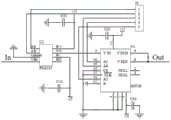
所述的转换器原理图如附图3所示,为由两个光电探测器CA1和CA2与一个常规的差分比较电路DA构成的集成印刷电路板,因而方便安装、拆卸和携带。所述的每个光电探测器CA1或CA2均由一个硅光电二极管SPD1或SPD2和一个常规运算放大器A1或A2组成负反馈运算放大电路。即:每个硅光电二极管SPD1或SPD2的负极先串联电容C1或C2后,再与运算放大器A1或A2的负极输入端相连,两个硅光电二极管SPD1和SPD2的正极和运算放大器A1和A2的正极输入端分别接地,运算放大器A1或A2的负极输入端先串联反馈电阻Rf1或Rf2后再与其输出端连接而组合成一个负反馈的运算放大电路。所述的两个硅光电二极管SPD1和SPD2分别装设在前述的两根光纤另一端的两个耦合器接口处,用以分别接收所述传感器头检测的绝缘子串泄漏电流的正、负半周波进行处理。所述的两个负反馈运算放大电路的输出端,分别串联电阻R1、R2后再分别与差分比较电路DA的第一级运算放大器A3和第二级运算放大器A4的正极输入端连接,用以将两个光电探测器CA1和CA2处理后的反映绝缘子串泄漏电流的正、负半周波电流,分别传输给差分比较电路DA的第一级运算放大器A3和第二级运算放大器A4进行处理。所述的差分比较电路DA由两级常规的运算放大器A3和A4构成,两级运算放大器A3和A4正极输入端分别接收两个前述光电探测器CA1和CA2输出的电信号V1out和V2out,第一级运算放大器A3的负极输入端通过电阻R3接地,第一级运算放大器A3的输出端信号
所述的信号前置处理模块原理图如附图4所示,包括滤波电路、程控放大电路、电平比较和脉冲计数电路。The schematic diagram of the signal pre-processing module is shown in Figure 4, including a filter circuit, a program-controlled amplifier circuit, a level comparison and a pulse counting circuit.
所述的滤波电路是泄漏电流经过采集后,成为频率分别为50HZ的工频电压信号和高频的脉冲信号,而且工频电压信号的幅值比高频脉冲电压小,因此设计高性能的滤波电路既能将两类信号进行分离,同时还能有效抑制外部信号的干扰,进而获得有效的泄漏电流信号。包括低通和高通两种滤波器。In the filter circuit, after the leakage current is collected, it becomes a power-frequency voltage signal and a high-frequency pulse signal with a frequency of 50HZ, and the amplitude of the power-frequency voltage signal is smaller than the high-frequency pulse voltage, so a high-performance filter is designed The circuit can not only separate the two types of signals, but also effectively suppress the interference of external signals, so as to obtain an effective leakage current signal. Both low-pass and high-pass filters are included.
所述的低通滤波电路设计为二阶Sallen-Key低通滤波器,电路图如附图5所示,电信号经过电阻R22输入到运算放大器芯片OP37的引脚3中,即+IN引脚,输出的电信号由引脚6即OUT引脚输出。设计低通滤波器时,先确定了滤波器的截止频率关,确定截止频率后,选择带宽合适的放大器。放大器的闭环带宽为滤波器的截止频率100倍。本专利采用Sallen—Key结构,滤波器的增益为-1V/V,闭环带宽的求解公式如下:Described low-pass filtering circuit is designed as a second-order Sallen-Key low-pass filter, and the circuit diagram is as shown in accompanying drawing 5, and electrical signal is input in the
GBWP≥100fcGBWP≥100fc
放大器的带宽确定后,进而对转换率进行估算,以保证滤波器不会产生信号失真。放大器转换率是由内部电流和电容决定的,当大信号通过放大器时,适当电流会对这些内部电容充电。充电速度取决于放大器的内部电阻、电容和电流值。为确保有源滤波器正确运作,所选的有源放大器的转换率SR应为:After the bandwidth of the amplifier is determined, the slew rate is estimated to ensure that the filter does not distort the signal. The slew rate of the amplifier is determined by the internal current and capacitance. When a large signal passes through the amplifier, the appropriate current will charge these internal capacitances. The charging speed depends on the internal resistance, capacitance and current value of the amplifier. To ensure correct operation of the active filter, the slew ratio SR of the selected active amplifier should be:
SR≥2πVopfcSR≥2πVopfc
式中,Vop为频率低于fc情况时期望的输出电压峰-峰值。where Vop is the expected peak-to-peak output voltage at frequencies lower than fc.
本专利只考虑泄漏电流的基波、三次谐波和五次谐波,其他高次谐波对泄漏电流有效值的计算影响很小,所以设计滤波器fc=300Hz,根据公式计算结果,可选用运算放大器的闭环带宽GBW﹥10KHz,转换率SR>l0V/ms的运算放大器,可形成性能良好的低通滤波器。This patent only considers the fundamental wave, the third harmonic and the fifth harmonic of the leakage current, and other higher harmonics have little influence on the calculation of the effective value of the leakage current, so the design filter fc=300Hz, according to the calculation results of the formula, can be selected The closed-loop bandwidth of the operational amplifier GBW﹥10KHz, and the operational amplifier with a conversion rate SR>l0V/ms can form a low-pass filter with good performance.
利用泄漏电流判断绝缘子的污秽程度需要关心电流的幅值而无需考虑电流的相位,因此,在设计低通滤波器时可以着眼于幅频响应,而不考虑相频响应。常用的巴特沃思滤波电路在小于截止频率ωc的范围内,具有最平幅度的响应,而在ω>ωc后幅频响应迅速下降。本专利所设计为二阶sallen-Key低通滤波器。Judging the degree of pollution of insulators by using leakage current needs to care about the amplitude of the current without considering the phase of the current. Therefore, when designing a low-pass filter, we can focus on the amplitude-frequency response without considering the phase-frequency response. The commonly used Butterworth filter circuit has the most flat amplitude response in the range less than the cut-off frequency ωc, and the amplitude-frequency response drops rapidly after ω>ωc. This patent is designed as a second-order sallen-Key low-pass filter.
利用Sallen-Key低通滤波器的设计公式,确定电阻R22、R23、R24和电容C21、C22的数值,本专利设计的低通滤波器截止频率为300Hz,品质因数为5。Use the Sallen-Key low-pass filter design formula to determine the values of resistors R22, R23, R24 and capacitors C21, C22. The cut-off frequency of the low-pass filter designed in this patent is 300 Hz, and the quality factor is 5.
所述的程控放大电路由可编程放大器PGA103与AD526串连来实现,如附图6所示,由低通滤波器输出的电信号输入到PGA103芯片的引脚4即VIN引脚,输出为引脚7即VO引脚与AD526芯片的引脚3即VIN相连,从引脚8和9输出。所述的程控放大电路由于泄漏电流幅值变化从0.5mA~300mA,有600倍的差别,所以传统的固定增益运放是没法使用的。Described program-controlled amplifying circuit is realized by programmable amplifier PGA103 and AD526 series connection, as shown in accompanying drawing 6, the
所述的PGA103与AD526都是软件可编程的单片仪表放大器,其增益范围分别为1、10、100和1、2、4、8、16。在增益为1时,带宽可达4MHz。PGA103与AD526与普通运算放大器构成的常规仪表放大器相比,前两者均提供了激光调整电阻和其它的单片集成电路技术,使得它的有源和无源器件被置于同一块芯片上,而且模拟地与数字地分离布置,这些器件能很好地匹配,保证了放大器具有高的共模抑制。此外,这些器件能在很大的温度范围内保持匹配,保证了仪表放大器在整个温度范围内的优良性能。The PGA103 and AD526 are both software-programmable single-chip instrumentation amplifiers, and their gain ranges are 1, 10, 100 and 1, 2, 4, 8, 16 respectively. When the gain is 1, the bandwidth can reach 4MHz. Compared with conventional instrumentation amplifiers composed of ordinary operational amplifiers, PGA103 and AD526 both provide laser-adjusted resistors and other monolithic integrated circuit technology, so that its active and passive devices are placed on the same chip. Moreover, the analog and digital grounds are arranged separately, and these devices can be well matched to ensure that the amplifier has high common-mode rejection. In addition, these devices are matched over a wide temperature range, ensuring excellent performance of the instrumentation amplifier over the entire temperature range.
所述的高通滤波器为压控二阶高通滤波电路,如附图7所示,经LED泄漏电流传感器转换后的电信号通过两个电容输入放大器芯片OP37的引脚3即+IN引脚,从引脚6即OUT脚输出。其通带放大倍数、截止频率和品质因数分别为:The high-pass filter is a voltage-controlled second-order high-pass filter circuit, as shown in Figure 7, the electrical signal converted by the LED leakage current sensor is input to the
由式上式可知,滤波器下限截止频率为4kHz,频率小于4kHz的泄漏电流将被衰减,不会对后面的脉冲测量及计数电路产生干扰,同时由于通带放大倍数为2,所以经过高通滤波电路后,电压幅值将被放大为原来的2倍。所述的电平比较以及脉冲计数电路如附图8所示。经高通滤波器产生的信号输入到快速比较器LM324芯片的input1+、input2+、input3+和input4+四个引脚中,分别于经电源分压后的电压进行计较,将单指数或者双指数波形通过正极性或负极性比较器全部转换为正极性的方波电平信号,然后输入到脉冲计数芯片,就可以得到一段时间内局放信号的脉冲数及脉冲幅值。输出的高低电平信号统一接到J4的插槽中便于与单片机采集连接。It can be seen from the above formula that the lower limit cut-off frequency of the filter is 4kHz, and the leakage current with a frequency less than 4kHz will be attenuated, and will not interfere with the subsequent pulse measurement and counting circuits. After the circuit, the voltage amplitude will be amplified to 2 times of the original. The level comparison and pulse counting circuit is shown in FIG. 8 . The signal generated by the high-pass filter is input to the four pins of input1+, input2+, input3+ and input4+ of the fast comparator LM324 chip, and the voltage after the voltage division of the power supply is calculated respectively, and the single-exponential or double-exponential waveform is passed through the positive polarity Or the negative polarity comparator is all converted into a positive polarity square wave level signal, and then input to the pulse counting chip, the pulse number and pulse amplitude of the partial discharge signal within a period of time can be obtained. The output high and low level signals are uniformly connected to the slot of J4, which is convenient for collecting and connecting with the single-chip microcomputer.
所述的前置处理电路主要分为两个部分,将泄漏电流信号进行分频处理,一个分支为低通滤波电路,对工频周期及低次谐波进行程控放大,然后接入单片机进行采样计算有效值等处理。另一路分支接高通滤波电路,对泄漏电流信号中的高频脉冲信号进行处理,即对各个范围内的脉冲进行计数。前置处理电路后连接单片机处理电路,对泄漏电流信号进行较为全面的分析处理。从而预测绝缘子污秽状态,为绝缘子污秽预警提供有效的数据。The pre-processing circuit is mainly divided into two parts, the leakage current signal is subjected to frequency division processing, and one branch is a low-pass filter circuit, which performs program-controlled amplification of the power frequency cycle and low-order harmonics, and then accesses the single-chip microcomputer for sampling Calculate the effective value and other processing. The other branch is connected to a high-pass filter circuit to process the high-frequency pulse signal in the leakage current signal, that is, to count the pulses in each range. After the pre-processing circuit is connected with the single-chip processing circuit, the leakage current signal is analyzed and processed comprehensively. In this way, the pollution status of insulators can be predicted, and effective data can be provided for early warning of insulator pollution.
所述的数据采集模块采用的是C8051F120单片机,利用该单片机系统,开发出的数据采集软件流程如附图9所示。The data acquisition module used is a C8051F120 single-chip microcomputer. Using this single-chip microcomputer system, the developed data acquisition software flow is shown in Figure 9.
所述的GPRS无线传输模块是以中国移动通信的GPRS网络作为通信媒介,将前端机处理得到的泄漏电流大小、有效值、环境温度、湿度等现场数据都是通过单片机的串口与GPRS通信模块实现时实数据传输,然后通过该模块传送到监控中心。Described GPRS wireless transmission module is to use the GPRS network of China Mobile as the communication medium, and the on-site data such as the leakage current size, effective value, ambient temperature, humidity obtained by the front-end computer processing are all realized by the serial port of the single-chip microcomputer and the GPRS communication module Real-time data transmission, and then sent to the monitoring center through this module.
所述的太阳能-蓄电池供电模块是选用太阳电池板与蓄电池组成的,太阳能电池板选购深圳万家好太阳能有限公司的18v-50w型,蓄电池选购佛山市南海雷斯顿电子科技有限公司的bN12V55AH型,电源控制器选购深圳万家好太阳能有限公司的SR-SL型。The solar-battery power supply module is composed of solar panels and batteries. The solar panels are 18v-50w from Shenzhen Wanjiahao Solar Energy Co., Ltd., and the batteries are from Foshan Nanhai Reston Electronic Technology Co., Ltd. bN12V55AH type, the power controller can choose SR-SL type from Shenzhen Wanjiahao Solar Energy Co., Ltd.
所述的数据采集分机平台用于显示采集到的泄漏电流幅值、有效值、脉冲数和温湿度。根据采集到的泄漏电流特征量,采用径向基神经网络的方法评定污秽绝缘子的污秽等级,并对污闪进行预警。所述的数据采集方法是进行系统初始化后启动看门狗,设置初始增益,启动AD采样,采集N周波电流值然后计算幅值和有效值,从而判断增益是否合适,若合适则保存,若不合适则重新设置增益再进行采集,循环下去直到增益合适为止。所述的数据分析方法是采用径向基神经网络的方法,输入参量为泄漏电流幅值、有效值、脉冲、和环境参量相对湿度,将绝缘子的污秽程度和污闪预警作为输出,污秽程度分为五个等级:I=[污秽轻度]、II=[污秽程度中度]、III=[污秽程度重度]和IV=[污秽程度严重]、V=[污秽程度非常严重],污闪的风险等级分为三个等级:A=[不报警]、B=[一般报警]、C=[危险报警],为了方便神经网络进行拟合建模,分别赋予0-1之间的一个量化的值。根据实验室人工污秽实验采集到的数据,需要进行插值处理,然后进行归一化处理,将归一化后的训练数据和测试数据输入到网络中,设置训练参数用训练数据训练网络并保存,用测试数据测试网络性能,将预测值与真实值进行对比,计算误差,判断此次的参数的训练能力是否最优,否则继续改变参数进行训练。训练的结果表明当SPREAD=2.5时,基于径向基神经网络的绝缘子污秽程度评定模型计算出来的结果与试验结果的最大绝对误差绝对值不超过0.05,与试验结果基本相符合;当SPREAD=1.8时,污秽预警与神经网络计算值之间的误差最小,网络的训练能力达到最优,至此两个网络训练完毕,基于径向基神经网络的绝缘子污秽程度和污闪预警模型建立。The data collection extension platform is used to display the collected leakage current amplitude, effective value, pulse number and temperature and humidity. According to the characteristic quantity of the leakage current collected, the radial basis neural network method is used to evaluate the pollution level of the polluted insulator, and the pollution flashover is given an early warning. The described data acquisition method is to start the watchdog after system initialization, set the initial gain, start AD sampling, collect the N cycle current value and then calculate the amplitude and effective value, thereby judging whether the gain is suitable, if it is suitable, save it, if not If it is suitable, reset the gain and then collect, and the cycle continues until the gain is suitable. The data analysis method adopts the radial basis neural network method, the input parameters are the leakage current amplitude, effective value, pulse, and the relative humidity of the environmental parameters, and the pollution degree of the insulator and the pollution flashover warning are used as outputs, and the pollution degree is classified into There are five grades: I=[mild pollution], II=[moderate pollution], III=[severe pollution], IV=[serious pollution], V=[very serious pollution], flashing pollution The risk level is divided into three levels: A=[no alarm], B=[general alarm], C=[dangerous alarm], in order to facilitate the fitting and modeling of the neural network, a quantitative value between 0-1 is assigned value. According to the data collected by the artificial pollution experiment in the laboratory, interpolation processing is required, and then normalization processing is performed. The normalized training data and test data are input into the network, and the training parameters are set to train the network with the training data and save. Use the test data to test the network performance, compare the predicted value with the real value, calculate the error, and judge whether the training ability of the parameters is optimal this time, otherwise continue to change the parameters for training. The training results show that when SPREAD=2.5, the maximum absolute error between the results calculated by the radial basis neural network-based insulator pollution degree evaluation model and the test results does not exceed 0.05, which is basically consistent with the test results; when SPREAD=1.8 When , the error between the pollution early warning and the calculated value of the neural network is the smallest, and the training ability of the network is optimal. So far, the two networks are trained, and the insulator pollution degree and pollution flashover early warning model based on the radial basis neural network is established.
Claims (2)
Priority Applications (1)
| Application Number | Priority Date | Filing Date | Title |
|---|---|---|---|
| CN201410065872.6ACN103823165A (en) | 2014-02-26 | 2014-02-26 | Insulator pollution flashover pre-warning method and system based on leakage currents |
Applications Claiming Priority (1)
| Application Number | Priority Date | Filing Date | Title |
|---|---|---|---|
| CN201410065872.6ACN103823165A (en) | 2014-02-26 | 2014-02-26 | Insulator pollution flashover pre-warning method and system based on leakage currents |
Publications (1)
| Publication Number | Publication Date |
|---|---|
| CN103823165Atrue CN103823165A (en) | 2014-05-28 |
Family
ID=50758320
Family Applications (1)
| Application Number | Title | Priority Date | Filing Date |
|---|---|---|---|
| CN201410065872.6APendingCN103823165A (en) | 2014-02-26 | 2014-02-26 | Insulator pollution flashover pre-warning method and system based on leakage currents |
Country Status (1)
| Country | Link |
|---|---|
| CN (1) | CN103823165A (en) |
Cited By (18)
| Publication number | Priority date | Publication date | Assignee | Title |
|---|---|---|---|---|
| CN104361216A (en)* | 2014-10-29 | 2015-02-18 | 国家电网公司 | Insulator pollution flashover early warning method on basis of variable weight analytic hierarchy process |
| CN104616060A (en)* | 2014-12-23 | 2015-05-13 | 南京工程学院 | Method for predicating contamination severity of insulator based on BP neural network and fuzzy logic |
| CN105137265A (en)* | 2015-08-26 | 2015-12-09 | 芜湖市凯鑫避雷器有限责任公司 | Insulator leakage current prediction method |
| CN105184067A (en)* | 2015-08-26 | 2015-12-23 | 芜湖市凯鑫避雷器有限责任公司 | Isolator pollution flashover state fuzzy evaluation method |
| CN105182118A (en)* | 2015-08-26 | 2015-12-23 | 芜湖市凯鑫避雷器有限责任公司 | Insulator contamination degree monitoring system |
| CN105242187A (en)* | 2015-11-09 | 2016-01-13 | 江苏省电力公司检修分公司 | Self-triggering power transmission line insulator pollution flashover early-warning device |
| CN105403759A (en)* | 2015-10-14 | 2016-03-16 | 嘉兴金尚节能科技有限公司 | Leakage current detection circuit for ADC sampling |
| CN105891688A (en)* | 2016-04-12 | 2016-08-24 | 苏州寅泽缕弦电子技术有限公司 | Insulator detection device |
| CN106597241A (en)* | 2017-01-24 | 2017-04-26 | 桂林师范高等专科学校 | Monitoring system for insulator arc-over |
| CN107515362A (en)* | 2017-08-08 | 2017-12-26 | 江苏大学 | A monitoring and early warning method for insulator pollution degree based on leakage current characteristics |
| CN108037411A (en)* | 2017-12-04 | 2018-05-15 | 国网江苏省电力有限公司检修分公司 | A kind of transmission line of electricity hidden danger electric discharge method for early warning |
| CN108181562A (en)* | 2018-01-18 | 2018-06-19 | 福州大学 | Insulator breakdown diagnostic device and method based on Study On Reliability Estimation Method For Cold Standby Systems |
| CN109959847A (en)* | 2017-12-25 | 2019-07-02 | 国家电网公司 | Optical fiber passive pollution flashover monitoring system |
| CN110472772A (en)* | 2019-07-09 | 2019-11-19 | 长沙能川信息科技有限公司 | A kind of disconnecting switch overheat method for early warning and a kind of disconnecting switch overheat early warning system |
| CN112307655A (en)* | 2020-10-21 | 2021-02-02 | 江苏省送变电有限公司 | Composite insulator contamination risk grade assessment method and system based on temperature detection |
| CN113791324A (en)* | 2021-09-16 | 2021-12-14 | 华北电力大学 | Pollution insulator flashover risk early warning system and method |
| CN116203462A (en)* | 2023-02-07 | 2023-06-02 | 广东电网有限责任公司 | Insulator fault detection system, method and medium |
| CN117368797A (en)* | 2023-11-17 | 2024-01-09 | 国网青海省电力公司海南供电公司 | Composite insulator flashover early warning method based on leakage current and EFS |
Citations (7)
| Publication number | Priority date | Publication date | Assignee | Title |
|---|---|---|---|---|
| CN201413371Y (en)* | 2009-04-09 | 2010-02-24 | 哈尔滨国力电气有限公司 | On-line monitoring and fault diagnosis system for substation equipment |
| CN102012451A (en)* | 2010-11-10 | 2011-04-13 | 重庆大学 | Light-emitting diode-based insulator leakage current fiber sensor system |
| WO2011080696A1 (en)* | 2009-12-29 | 2011-07-07 | Kuzin, Anton | Fiber optic current sensor |
| CN102156214A (en)* | 2011-04-29 | 2011-08-17 | 重庆大学 | Double-light-path leakage current optical fiber sensor device |
| CN102221641A (en)* | 2011-04-07 | 2011-10-19 | 北京交通大学 | On-line monitoring system for leakage current of high-voltage power transmission line insulator |
| CN102331540A (en)* | 2011-05-26 | 2012-01-25 | 江苏科技大学 | An on-line monitoring device and method for corona discharge of UHV transmission lines |
| CN103558498A (en)* | 2013-11-18 | 2014-02-05 | 华北电力大学 | Insulator pollution flashover leakage current signal sparse representation method based on wavelet analysis |
- 2014
- 2014-02-26CNCN201410065872.6Apatent/CN103823165A/enactivePending
Patent Citations (7)
| Publication number | Priority date | Publication date | Assignee | Title |
|---|---|---|---|---|
| CN201413371Y (en)* | 2009-04-09 | 2010-02-24 | 哈尔滨国力电气有限公司 | On-line monitoring and fault diagnosis system for substation equipment |
| WO2011080696A1 (en)* | 2009-12-29 | 2011-07-07 | Kuzin, Anton | Fiber optic current sensor |
| CN102012451A (en)* | 2010-11-10 | 2011-04-13 | 重庆大学 | Light-emitting diode-based insulator leakage current fiber sensor system |
| CN102221641A (en)* | 2011-04-07 | 2011-10-19 | 北京交通大学 | On-line monitoring system for leakage current of high-voltage power transmission line insulator |
| CN102156214A (en)* | 2011-04-29 | 2011-08-17 | 重庆大学 | Double-light-path leakage current optical fiber sensor device |
| CN102331540A (en)* | 2011-05-26 | 2012-01-25 | 江苏科技大学 | An on-line monitoring device and method for corona discharge of UHV transmission lines |
| CN103558498A (en)* | 2013-11-18 | 2014-02-05 | 华北电力大学 | Insulator pollution flashover leakage current signal sparse representation method based on wavelet analysis |
Non-Patent Citations (3)
| Title |
|---|
| 夏青: ""线路绝缘子交流污秽预测的新特征量研究"", 《中国优秀硕士学位论文全文数据库工程科技Ⅱ辑》* |
| 胡岳: ""基于无线通信的手持式低零值绝缘子检测仪的研制"", 《中国优秀硕士学位论文全文数据库工程科技Ⅱ辑》* |
| 黄欢: ""基于泄漏电流特征量的绝缘子污闪预测的研究"", 《中国优秀硕士学位论文全文数据库工程科技Ⅱ辑》* |
Cited By (24)
| Publication number | Priority date | Publication date | Assignee | Title |
|---|---|---|---|---|
| CN104361216B (en)* | 2014-10-29 | 2017-06-23 | 国网河南省电力公司电力科学研究院 | A kind of insulator contamination method for early warning based on change power analytic hierarchy process (AHP) |
| CN104361216A (en)* | 2014-10-29 | 2015-02-18 | 国家电网公司 | Insulator pollution flashover early warning method on basis of variable weight analytic hierarchy process |
| CN104616060A (en)* | 2014-12-23 | 2015-05-13 | 南京工程学院 | Method for predicating contamination severity of insulator based on BP neural network and fuzzy logic |
| CN104616060B (en)* | 2014-12-23 | 2018-03-27 | 南京工程学院 | Insulator dirty degree Forecasting Methodology based on BP neural network and fuzzy logic |
| CN105137265A (en)* | 2015-08-26 | 2015-12-09 | 芜湖市凯鑫避雷器有限责任公司 | Insulator leakage current prediction method |
| CN105184067A (en)* | 2015-08-26 | 2015-12-23 | 芜湖市凯鑫避雷器有限责任公司 | Isolator pollution flashover state fuzzy evaluation method |
| CN105182118A (en)* | 2015-08-26 | 2015-12-23 | 芜湖市凯鑫避雷器有限责任公司 | Insulator contamination degree monitoring system |
| CN105403759B (en)* | 2015-10-14 | 2018-03-27 | 嘉兴金尚节能科技有限公司 | For the leakage current detection circuit of ADC samplings |
| CN105403759A (en)* | 2015-10-14 | 2016-03-16 | 嘉兴金尚节能科技有限公司 | Leakage current detection circuit for ADC sampling |
| CN105242187A (en)* | 2015-11-09 | 2016-01-13 | 江苏省电力公司检修分公司 | Self-triggering power transmission line insulator pollution flashover early-warning device |
| CN105891688A (en)* | 2016-04-12 | 2016-08-24 | 苏州寅泽缕弦电子技术有限公司 | Insulator detection device |
| CN106597241A (en)* | 2017-01-24 | 2017-04-26 | 桂林师范高等专科学校 | Monitoring system for insulator arc-over |
| CN107515362A (en)* | 2017-08-08 | 2017-12-26 | 江苏大学 | A monitoring and early warning method for insulator pollution degree based on leakage current characteristics |
| CN108037411A (en)* | 2017-12-04 | 2018-05-15 | 国网江苏省电力有限公司检修分公司 | A kind of transmission line of electricity hidden danger electric discharge method for early warning |
| CN109959847B (en)* | 2017-12-25 | 2024-03-29 | 国家电网公司 | Optical fiber passive pollution flashover monitoring system |
| CN109959847A (en)* | 2017-12-25 | 2019-07-02 | 国家电网公司 | Optical fiber passive pollution flashover monitoring system |
| CN108181562A (en)* | 2018-01-18 | 2018-06-19 | 福州大学 | Insulator breakdown diagnostic device and method based on Study On Reliability Estimation Method For Cold Standby Systems |
| CN110472772A (en)* | 2019-07-09 | 2019-11-19 | 长沙能川信息科技有限公司 | A kind of disconnecting switch overheat method for early warning and a kind of disconnecting switch overheat early warning system |
| CN110472772B (en)* | 2019-07-09 | 2020-11-10 | 长沙能川信息科技有限公司 | Overheating early warning method for isolating switch and overheating early warning system for isolating switch |
| CN112307655A (en)* | 2020-10-21 | 2021-02-02 | 江苏省送变电有限公司 | Composite insulator contamination risk grade assessment method and system based on temperature detection |
| CN112307655B (en)* | 2020-10-21 | 2023-12-05 | 江苏省送变电有限公司 | Composite insulator pollution risk level assessment method and system based on temperature detection |
| CN113791324A (en)* | 2021-09-16 | 2021-12-14 | 华北电力大学 | Pollution insulator flashover risk early warning system and method |
| CN116203462A (en)* | 2023-02-07 | 2023-06-02 | 广东电网有限责任公司 | Insulator fault detection system, method and medium |
| CN117368797A (en)* | 2023-11-17 | 2024-01-09 | 国网青海省电力公司海南供电公司 | Composite insulator flashover early warning method based on leakage current and EFS |
Similar Documents
| Publication | Publication Date | Title |
|---|---|---|
| CN103823165A (en) | Insulator pollution flashover pre-warning method and system based on leakage currents | |
| CN106093720B (en) | High-voltage cable condition monitoring system based on protective grounding box and its realization method | |
| CN201355384Y (en) | System for detecting and managing partial discharge of switch cabinet on-line | |
| CN105866638B (en) | A kind of city net cable connector state of insulation on-line monitoring prior-warning device and method | |
| CN105910649A (en) | High voltage cable state monitoring system based on direct grounding box and realization method thereof | |
| CN101576593B (en) | Array Type Inferior Insulator Local Electric Field Detection Device and Reverse Diagnosis Method | |
| CN102331540A (en) | An on-line monitoring device and method for corona discharge of UHV transmission lines | |
| CN104330615B (en) | The how identical survey devices and methods therefor of arrester and transformer based on fft algorithm | |
| CN110609220A (en) | A detection and evaluation system for transmission cable insulation status based on multiple signal acquisition and analysis | |
| CN103529057A (en) | Device and method for detecting pollution of insulator by image analysis combined with ultrasonic principle | |
| CN203337722U (en) | Voltage and current collecting device of grid overhead transmission line | |
| CN112505430B (en) | A passive high-voltage capacitor capacitance online monitoring system and method | |
| CN117310405A (en) | Time/frequency domain dielectric response detection system and method for oiled paper insulating sleeve | |
| CN102156214B (en) | A Dual Optical Path Leakage Current Optical Fiber Sensor Device | |
| CN112129348A (en) | Transformer oil leakage monitoring device based on oil level monitoring | |
| CN116754903A (en) | A non-contact overhead line pollution flashover early warning system and method | |
| CN209586594U (en) | Wind-powered electricity generation multichannel lightning monitoring system | |
| CN204964656U (en) | Portable insulator intellectual detection system appearance | |
| CN205404706U (en) | Electric automobile fills electric pile's electric energy quality dynamic monitoring system based on DSP | |
| CN109839531A (en) | A kind of capacitance type potential transformer and its Transmission Characteristics system and operating method | |
| CN207336615U (en) | A kind of Zinc-Oxide Arrester electrification detection system | |
| CN106771882B (en) | An offline detection and positioning method and device for potential problems in high-voltage cables | |
| CN217360058U (en) | Lightning current monitoring device | |
| CN215218981U (en) | Passive high-voltage capacitor capacitance on-line monitoring system | |
| CN108761297A (en) | A kind of dry-type air-core reactor partial discharges fault on-line computing model based on high-frequency signal |
Legal Events
| Date | Code | Title | Description |
|---|---|---|---|
| C06 | Publication | ||
| PB01 | Publication | ||
| C10 | Entry into substantive examination | ||
| SE01 | Entry into force of request for substantive examination | ||
| WD01 | Invention patent application deemed withdrawn after publication | ||
| WD01 | Invention patent application deemed withdrawn after publication | Application publication date:20140528 |