CN103818128A - Tape cartridge and tape printer - Google Patents
Tape cartridge and tape printerDownload PDFInfo
- Publication number
- CN103818128A CN103818128ACN201310727219.7ACN201310727219ACN103818128ACN 103818128 ACN103818128 ACN 103818128ACN 201310727219 ACN201310727219 ACN 201310727219ACN 103818128 ACN103818128 ACN 103818128A
- Authority
- CN
- China
- Prior art keywords
- tape
- rotation guide
- tape drum
- core
- guide portion
- Prior art date
- Legal status (The legal status is an assumption and is not a legal conclusion. Google has not performed a legal analysis and makes no representation as to the accuracy of the status listed.)
- Granted
Links
Images


Classifications
- B—PERFORMING OPERATIONS; TRANSPORTING
- B41—PRINTING; LINING MACHINES; TYPEWRITERS; STAMPS
- B41J—TYPEWRITERS; SELECTIVE PRINTING MECHANISMS, i.e. MECHANISMS PRINTING OTHERWISE THAN FROM A FORME; CORRECTION OF TYPOGRAPHICAL ERRORS
- B41J15/00—Devices or arrangements of selective printing mechanisms, e.g. ink-jet printers or thermal printers, specially adapted for supporting or handling copy material in continuous form, e.g. webs
- B41J15/04—Supporting, feeding, or guiding devices; Mountings for web rolls or spindles
- B41J15/044—Cassettes or cartridges containing continuous copy material, tape, for setting into printing devices
- B—PERFORMING OPERATIONS; TRANSPORTING
- B41—PRINTING; LINING MACHINES; TYPEWRITERS; STAMPS
- B41J—TYPEWRITERS; SELECTIVE PRINTING MECHANISMS, i.e. MECHANISMS PRINTING OTHERWISE THAN FROM A FORME; CORRECTION OF TYPOGRAPHICAL ERRORS
- B41J3/00—Typewriters or selective printing or marking mechanisms characterised by the purpose for which they are constructed
- B41J3/407—Typewriters or selective printing or marking mechanisms characterised by the purpose for which they are constructed for marking on special material
- B41J3/4075—Tape printers; Label printers
- B—PERFORMING OPERATIONS; TRANSPORTING
- B41—PRINTING; LINING MACHINES; TYPEWRITERS; STAMPS
- B41J—TYPEWRITERS; SELECTIVE PRINTING MECHANISMS, i.e. MECHANISMS PRINTING OTHERWISE THAN FROM A FORME; CORRECTION OF TYPOGRAPHICAL ERRORS
- B41J32/00—Ink-ribbon cartridges
Landscapes
- Impression-Transfer Materials And Handling Thereof (AREA)
- Printers Characterized By Their Purpose (AREA)
- Handling Of Continuous Sheets Of Paper (AREA)
- Replacement Of Web Rolls (AREA)
- Basic Packing Technique (AREA)
Abstract
Description
Translated fromChinese本发明专利申请是发明名称为“带盒及带印刷装置”、申请日为2011年6月22日、申请号为“201110169424.7”的发明专利申请的分案申请。The patent application for the present invention is a divisional application of the invention patent application with the invention name "tape cassette and tape printing device", the application date is June 22, 2011, and the application number is "201110169424.7".
技术领域technical field
本发明涉及将带芯以能够自如旋转的方式轴支承在盒壳体内、并且将卷绕于带芯的带以能够送出的方式进行收纳的带盒及带印刷装置。The present invention relates to a tape cassette and a tape printing apparatus in which a tape core is rotatably supported in a cassette case, and a tape wound around the tape core is housed in a feedable manner.
背景技术Background technique
以往,周知由带芯及盒壳体构成的带盒,所述带芯具有芯主体和圆板状的肋部,所述芯主体在外周面卷绕有带,所述圆板状的肋部设在芯主体的内周面的中段位置并被旋转自如地轴支承于下壳体的突起,所述盒壳体分割为上下两部分(参照专利文献1)。Conventionally, there is known a tape cassette composed of a tape core having a core body and a disc-shaped rib, the core body having a tape wound around its outer peripheral surface, and a cassette case. The cartridge case is provided in the middle position of the inner peripheral surface of the core body and is rotatably supported by a protrusion of a lower case divided into upper and lower parts (refer to Patent Document 1).
带盒的带芯中,肋部设于芯主体的内周面的轴向中间部,因此不管贯穿插入于突起的带芯的朝向为哪个朝向都是可以的,能够将组装时的安装错误防止于未然。In the tape core of the tape cassette, since the rib is provided at the axially intermediate portion of the inner peripheral surface of the core body, the orientation of the tape core inserted through the protrusion can be any direction, and it is possible to prevent installation errors during assembly. Before it happens.
专利文献1:日本特开平10-071756号公报Patent Document 1: Japanese Patent Application Laid-Open No. 10-071756
但是,带芯仅利用肋部以预定的尺寸公差轴支承于突起,因此伴随由带的送出等引起的带芯的旋转而产生了带芯的“晃动”等。因此,当拉出带的力在带的宽度方向上不均匀地进行作用时,存在带芯倾斜、带一边倾斜移动一边被送出等问题。However, since the tape core is axially supported by the protrusion with predetermined dimensional tolerances only by the ribs, “wobbling” of the tape core or the like occurs due to rotation of the tape core due to feeding out of the tape or the like. Therefore, when the force for pulling out the tape acts unevenly in the width direction of the tape, the tape core is inclined, and the tape is fed out while being inclined.
发明内容Contents of the invention
本发明的课题在于,提供能够抑制带芯的倾斜且能够使带芯的旋转稳定的带盒及带印刷装置。An object of the present invention is to provide a tape cassette and a tape printing device capable of suppressing the inclination of the tape core and stabilizing the rotation of the tape core.
本发明的带盒被安装于具有盒安装部的带印刷装置,该盒安装部设置有配合轴和从所述配合轴的外周面突出的配合突起,其特征在于,所述带盒具有:带芯,其具有在外周面卷绕有带的芯主体和形成于所述芯主体的轴心的轴孔;以及收纳所述带芯的盒壳体,所述盒壳体具有:轴支承部,其贯穿插入于所述轴孔,并将所述带芯轴支承成能够自如旋转;以及旋转引导部,其从所述轴支承部的外周面突出,在所述轴支承部设置有供所述配合轴配合的中空部,在所述旋转引导部设置有供所述配合突起配合的凹部。The tape cassette of the present invention is mounted on a tape printing device having a cassette mounting portion provided with an engaging shaft and an engaging protrusion protruding from an outer peripheral surface of the engaging shaft, wherein the tape cassette has: a core having a core main body with a tape wound around its outer peripheral surface; an axial hole formed in the axial center of the core main body; and a case housing for accommodating the tape core, the case case having: It is inserted through the shaft hole, and supports the belt mandrel so as to be rotatable; and a rotation guide protrudes from the outer peripheral surface of the shaft support, and a The hollow part to which the shaft is fitted is provided with a concave part into which the fitting protrusion fits in the rotation guide part.
此外,优选的是,通过所述配合轴与所述轴支承部的所述中空部配合,所述配合突起与所述旋转引导部的所述凹部配合,由此将所述带盒定位于所述盒安装部。In addition, it is preferable that the engaging protrusion is engaged with the concave portion of the rotation guide portion by the engaging shaft engaging with the hollow portion of the shaft supporting portion, thereby positioning the cassette at the box installation section.
此外,优选的是,所述旋转引导部部分地设置在所述轴支承部的周向上。Furthermore, it is preferable that the rotation guide portion is partially provided in a circumferential direction of the shaft support portion.
此外,优选的是,所述旋转引导部设置在所述轴支承部的整周范围内。Furthermore, it is preferable that the rotation guide portion is provided over the entire circumference of the shaft support portion.
此外,优选的是,所述旋转引导部与所述芯主体的内周面滑动接触。Furthermore, it is preferable that the rotation guide is in sliding contact with the inner peripheral surface of the core main body.
此外,优选的是,所述轴支承部和所述旋转引导部与所述盒壳体一体地成型。Furthermore, it is preferable that the shaft support portion and the rotation guide portion are integrally formed with the cartridge case.
本发明的带印刷装置能够安装上述任意一项所述的带盒,其特征在于,所述带印刷装置具有所述盒安装部,该盒安装部设置有所述配合轴和从所述配合轴的外周面突出的所述配合突起。The tape printing device of the present invention is capable of mounting the tape cassette described in any one of the above, and is characterized in that the tape printing device has the cassette mounting portion, and the cassette mounting portion is provided with the coupling shaft and the coupling axis from the coupling shaft. The fitting protrusion protrudes from the outer peripheral surface.
附图说明Description of drawings
图1是带印刷装置的开盖状态的外观立体图。FIG. 1 is an external perspective view of the tape printing device in an opened state.
图2是将上壳体剖开后的第1实施方式的带盒的俯视图。Fig. 2 is a plan view of the tape cassette according to the first embodiment with the upper case cut away.
图3是带盒的表面和背面立体图。Fig. 3 is a front and rear perspective view of the cassette.
图4是带盒的分解立体图。Fig. 4 is an exploded perspective view of the tape cassette.
图5是图2所示的带盒的沿A-A线的剖视图及盒安装部的剖视图。5 is a cross-sectional view along line AA of the tape cassette shown in FIG. 2 and a cross-sectional view of a cassette mounting portion.
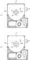
图6是省略了上壳体的第2实施方式的带盒的俯视图。Fig. 6 is a plan view of a tape cassette according to a second embodiment in which an upper case is omitted.
图7是省略了上壳体的带盒,其中(a)是第3实施方式的带盒的俯视图,(b)是其变形例的带盒的俯视图。7 is a tape cassette without an upper case, wherein (a) is a top view of the tape cassette according to the third embodiment, and (b) is a top view of a tape cassette according to a modified example thereof.
标号说明Label description
1:带印刷装置;2:带盒;18b:配合突起;21a:印刷带;21b:带芯;25:盒壳体;26:芯主体;27:肋部;28:轴孔;41:轴支承部;42:旋转引导部。1: belt printing device; 2: belt box; 18b: mating protrusion; 21a: printing belt; 21b: belt core; 25: box shell; 26: core body; 27: rib; 28: shaft hole; 41: shaft Supporting part; 42: rotating guide part.
具体实施方式Detailed ways
下面,一边参照附图一边对第1实施方式所涉及的本发明的带印刷装置进行说明。关于该带印刷装置,从所安装的带盒中送出印刷带及墨带,在施加了张力的状态下一边使它们同时移动一边进行印刷,然后将印刷带的已印刷部分切断,从而制作成记录单(带片)。Next, the tape printing device of the present invention according to the first embodiment will be described with reference to the drawings. With regard to this tape printing device, a printing tape and an ink ribbon are sent out from a mounted tape cassette, and printing is performed while moving them simultaneously while tension is applied, and then the printed portion of the printing tape is cut to produce a record. Single (with sheet).
参照图1及图2,对带印刷装置1等进行说明。图1是带印刷装置1的开盖状态的外观立体图。图2是将上壳体25a剖开后的带盒2的俯视图。带印刷装置1包括:装置主体10,其形成带印刷装置1的外壳;盒安装部12,该盒安装部12凹陷形成于开闭盖11的内侧,并且收纳有印刷带21a等的带盒2以能够自如装卸的方式安装于该盒安装部12;带传送单元13,其一边从带盒2送出印刷带21a一边对印刷带21a进行传送;以及切断器单元14,其将已印刷的印刷带21a切断。用户操作在装置主体10的上表面配置的键盘15,一边对显示出操作结果等的显示器16进行确认一边执行印刷动作。The tape printing device 1 and the like will be described with reference to FIGS. 1 and 2 . FIG. 1 is an external perspective view of the tape printing apparatus 1 in an opened state. FIG. 2 is a plan view of the
带盒2包括:将印刷带21a卷绕于带芯21b而形成的带体21;将墨带22a卷绕于墨带芯22b而形成的墨带体22;卷绕使用后的墨带22a的卷绕芯23;以及将印刷带21a从带体21送出并对印刷带21a进行传送的压辊(platen roller)24。The
带传送单元13包括:多个驱动轴17,它们使压辊24及卷绕芯23旋转,以使安装于盒安装部12的带盒2内的印刷带21a及墨带22a移动;定位突起18,其与带芯21b卡合而进行定位;以及驱动机构(图示省略),其使多个驱动轴17同步旋转。The
当将带盒2安装于盒安装部12时,热敏头19隔着印刷带21a及墨带22a与压辊24抵接,成为印刷待机状态(参照图2)。当印刷开始时,墨带22a在压辊24的部分与印刷带21a重叠着同时移动。然后,通过热敏头19进行了印刷处理的印刷带21a被向带盒2及装置主体10的外部送出,通过切断器单元14将已印刷部分沿带宽度方向切断,从而制作成带片(记录单)。另一方面,墨带22a在带盒2内沿预定的路径被传送并卷绕于卷绕芯23。When the
接着,参照图2至图5,对带盒2进行详细说明。图3是带盒2的表面和背面立体图。图4是带盒2的分解立体图。图5是图2所示的带盒2的沿A-A线的剖视图及盒安装部12的剖视图。关于带盒2,通过由上壳体25a和下壳体25b构成的盒壳体25来形成带盒2的外壳,在盒壳体25内收纳有上述的带体21、墨带体22、卷绕芯23及压辊24。上壳体25a及下壳体25b通过在接合端面形成的销及贯通孔而被压入接合(能够分解和再利用)。Next, the
构成带体21的带芯21b由以下部分一体形成:在外周面卷绕有印刷带21a的芯主体26;在芯主体26的内周面的轴向中间部突出设置的肋部27;以及在肋部27的轴心形成的轴孔28(参照图2及图5)。芯主体26形成为中空圆筒形,肋部27形成为在轴心开口出轴孔28的中空圆板状。The
另外,在芯主体26的内周面组装有防止反转机构31,该防止反转机构31用于防止印刷带21a的送出端被向盒壳体25内拉入(参照图4及图5)。防止反转机构31具有:棘轮槽(图示省略),其由锯齿状的棘轮构成,所述棘轮分别形成在上述的肋部27的表面和背面,并形成为仅允许向印刷带21a的送出方向旋转;以及防止反转弹簧32(所谓的螺旋弹簧),该防止反转弹簧32的两端部分别与肋部27及上壳体25a抵接,并且在该防止反转弹簧32的下侧端部形成有呈直线状延长的线状卡定部33。In addition, an
下壳体25b具有:轴支承部41,其贯穿插入于轴孔28并将带芯21b轴支承成能够自如旋转;以及旋转引导部42,其以与芯主体26的内周面滑动接触的方式附加设置于轴支承部41。The
轴支承部41形成为从下壳体25b直立设置的中空圆筒形,从其上端形成有纵槽43。纵槽43一直切入至比安装在轴支承部41的带芯21b的棘轮槽要低的位置(参照图5的(a))。The
因此,当防止反转弹簧32以使线状卡定部33与纵槽43对位的方式被放入到轴支承部41的内周部分时,线状卡定部33载置于棘轮槽上,进而,当在该状态下安装上壳体25a时,防止反转弹簧32被压缩,其线状卡定部33被按压于棘轮槽(参照图5的(a))。由此,带芯21b向印刷带21a的送出方向(图2中的B方向)的旋转被允许,而向其反方向的旋转则被阻止。另一方面,在将带盒2安装于盒安装部12时,上述的定位突起18从下侧推压防止反转弹簧32,解除线状卡定部33相对于棘轮槽的卡合(参照图5的(b))。即,线状卡定部33从棘轮槽离开,从而带芯21b能够自由旋转。另外,防止反转弹簧32也可以形成为安装于轴支承部41的外周面的结构。Therefore, when the
旋转引导部42在轴支承部41的基端部分从轴支承部41凸出设置,该旋转引导部42具有预定的厚度且与下壳体25b一体地成型。另外,本实施方式中,在图2中的上侧设置有一处旋转引导部42。旋转引导部42中,与芯主体26的内周面滑动接触的部分形成为具有与该内周面大致相同的曲率,从而不会妨碍带芯21b的旋转。根据这种结构,当带芯21b的轴孔28由下壳体25b支承时,芯主体26的肋部27与轴支承部41滑动接触,并且旋转引导部42与芯主体26的内周面滑动接触。因此,带芯21b在轴支承部41和旋转引导部42这2个部位被旋转自如地轴支承于下壳体25b内。由此,带芯21b以不“晃动”(不倾斜)的方式旋转,能够防止卷绕于带芯21b的印刷带21a一边倾斜移动一边被送出。A
另外,在下壳体25b的下表面(背面)形成有配合开口部44,该配合开口部44由作为轴支承部41的内周面的中空部44a和通过旋转引导部42形成的凹部44b一体地构成(参照图3的(b))。In addition, on the lower surface (back surface) of the
接着,对以能够自如装卸的方式安装带盒2的盒安装部12进行说明。在盒安装部12,如上所述地直立设置有与带芯21b卡合而进行定位的定位突起18(参照图1及图5)。定位突起18一体地设置有:配合轴18a,当带盒2安装于盒安装部12时,该配合轴18a与轴支承部41的中空部44a配合;和配合突起18b,其与通过旋转引导部42形成的凹部44b配合。即,在将带盒2安装于盒安装部12时,定位突起18与下壳体25b的下表面的配合开口部44配合,从而将带盒2定位于盒安装部12并以不能旋转的方式固定。由此,能够消除盒安装部12中的带盒2自身的“晃动”,能够使带盒2内的带芯21b的旋转稳定。Next, the
根据以上的结构,通过肋部27和旋转引导部42,能够使带芯21b的旋转稳定,能够正确地送出卷绕于带芯21b的印刷带21a。According to the above structure, the rotation of the
另外,在本实施方式中,旋转引导部42附加设置于轴支承部41,并与轴支承部41一体地形成,但也可以在与轴支承部41分离的位置独立地设置旋转引导部42。In this embodiment, the
(第2实施方式)(Second embodiment)
参照图6,说明第2实施方式的带盒2。另外,省略与第1实施方式相同的说明。图6是省略了上壳体25a的第2实施方式的带盒2的俯视图。第2实施方式的带盒2中,旋转引导部42配置在印刷带21a被送出而解开卷绕状态的位置的法线上。这样,通过在产生倾斜的力集中作用的(施加的力最大的)部分设置旋转引导部42,能够可靠地防止带芯21b倾斜,能够保证无“晃动”的、稳定的旋转。Referring to Fig. 6, a
(第3实施方式)(third embodiment)
图7的(a)是第3实施方式的带盒2的俯视图。另外,省略与第1实施方式相同的说明。该带盒2在轴支承部41的周向上等间隔地设置有多个(在本实施方式中为4个)旋转引导部42。该情况下,旋转引导部42的数量及位置是任意的。根据该结构,能够阻止带芯21b向多个方向的倾斜,能够可靠地防止带芯21b的“晃动”。(a) of FIG. 7 is a top view of the
(第3实施方式的变形例)(Modification of the third embodiment)
图7的(b)是第3实施方式的变形例的带盒2的俯视图。该带盒2中,旋转引导部42设置在轴支承部41的整周范围内。根据该结构,能够进一步阻止带芯21b的倾斜,能够可靠地防止带芯21b的“晃动”。(b) of FIG. 7 is a plan view of a
Claims (9)
Applications Claiming Priority (3)
| Application Number | Priority Date | Filing Date | Title |
|---|---|---|---|
| JP2010145005AJP5556435B2 (en) | 2010-06-25 | 2010-06-25 | Tape cartridge |
| JP2010-145005 | 2010-06-25 | ||
| CN201110169424.7ACN102295197B (en) | 2010-06-25 | 2011-06-22 | With cassette and with printing unit |
Related Parent Applications (1)
| Application Number | Title | Priority Date | Filing Date |
|---|---|---|---|
| CN201110169424.7ADivisionCN102295197B (en) | 2010-06-25 | 2011-06-22 | With cassette and with printing unit |
Publications (2)
| Publication Number | Publication Date |
|---|---|
| CN103818128Atrue CN103818128A (en) | 2014-05-28 |
| CN103818128B CN103818128B (en) | 2017-04-12 |
Family
ID=44629622
Family Applications (2)
| Application Number | Title | Priority Date | Filing Date |
|---|---|---|---|
| CN201110169424.7AActiveCN102295197B (en) | 2010-06-25 | 2011-06-22 | With cassette and with printing unit |
| CN201310727219.7AExpired - Fee RelatedCN103818128B (en) | 2010-06-25 | 2011-06-22 | Tape cartridge and tape printer |
Family Applications Before (1)
| Application Number | Title | Priority Date | Filing Date |
|---|---|---|---|
| CN201110169424.7AActiveCN102295197B (en) | 2010-06-25 | 2011-06-22 | With cassette and with printing unit |
Country Status (8)
| Country | Link |
|---|---|
| US (3) | US8974131B2 (en) |
| EP (1) | EP2585306B1 (en) |
| JP (1) | JP5556435B2 (en) |
| KR (3) | KR101421118B1 (en) |
| CN (2) | CN102295197B (en) |
| RU (1) | RU2543424C2 (en) |
| TW (3) | TWI430894B (en) |
| WO (1) | WO2011161955A1 (en) |
Cited By (3)
| Publication number | Priority date | Publication date | Assignee | Title |
|---|---|---|---|---|
| CN106103116A (en)* | 2014-03-24 | 2016-11-09 | 精工爱普生株式会社 | Tape drum |
| CN107206811A (en)* | 2015-02-23 | 2017-09-26 | 精工爱普生株式会社 | With printing equipment and with print system |
| CN107867093A (en)* | 2014-10-16 | 2018-04-03 | 精工爱普生株式会社 | Tape drum |
Families Citing this family (21)
| Publication number | Priority date | Publication date | Assignee | Title |
|---|---|---|---|---|
| JP5556435B2 (en) | 2010-06-25 | 2014-07-23 | セイコーエプソン株式会社 | Tape cartridge |
| JP6015266B2 (en)* | 2012-09-13 | 2016-10-26 | コクヨ株式会社 | Transfer tool and transfer tool refill |
| US9539833B2 (en)* | 2013-03-21 | 2017-01-10 | Seiko Epson Corporation | Tape cartridge and tape printing apparatus |
| JP6172457B2 (en)* | 2013-10-31 | 2017-08-02 | ブラザー工業株式会社 | Tape cartridge |
| JP6218657B2 (en)* | 2014-03-24 | 2017-10-25 | セイコーエプソン株式会社 | Tape cartridge |
| EP3124258B1 (en) | 2014-03-24 | 2019-04-17 | Seiko Epson Corporation | Tape printing device and tape printing system |
| JP6144221B2 (en)* | 2014-03-24 | 2017-06-07 | セイコーエプソン株式会社 | Tape cartridge |
| JP6113207B2 (en)* | 2014-03-24 | 2017-04-12 | セイコーエプソン株式会社 | Tape cartridge |
| JP6346766B2 (en) | 2014-03-24 | 2018-06-20 | セイコーエプソン株式会社 | Tape cartridge |
| JP5876125B2 (en)* | 2014-09-19 | 2016-03-02 | セイコーエプソン株式会社 | Tape cartridge |
| JP2016068407A (en)* | 2014-09-30 | 2016-05-09 | セイコーエプソン株式会社 | Tape cartridge |
| JP6508904B2 (en)* | 2014-09-30 | 2019-05-08 | セイコーエプソン株式会社 | Tape cartridge |
| JP6297514B2 (en)* | 2015-03-19 | 2018-03-20 | セイコーエプソン株式会社 | Tape cartridge |
| JP6509006B2 (en)* | 2015-03-30 | 2019-05-08 | セイコーエプソン株式会社 | Tape cartridge |
| JP6561750B2 (en) | 2015-09-15 | 2019-08-21 | セイコーエプソン株式会社 | Tape cartridge |
| WO2019189711A1 (en)* | 2018-03-29 | 2019-10-03 | セイコーエプソン株式会社 | Ribbon cartridge |
| KR102580618B1 (en)* | 2018-03-29 | 2023-09-19 | 세이코 엡슨 가부시키가이샤 | Ribbon cartridge and printing device |
| JP6535796B2 (en)* | 2018-08-03 | 2019-06-26 | セイコーエプソン株式会社 | Tape cartridge |
| CN111376620B (en)* | 2018-12-26 | 2022-04-29 | 精工爱普生株式会社 | Cartridge to be mounted on tape printer |
| JP7456204B2 (en)* | 2020-03-11 | 2024-03-27 | セイコーエプソン株式会社 | cartridge |
| JP2024047408A (en)* | 2022-09-26 | 2024-04-05 | セイコーエプソン株式会社 | Tape cartridges, tape rolls and tape cartridge sets |
Citations (7)
| Publication number | Priority date | Publication date | Assignee | Title |
|---|---|---|---|---|
| US5518328A (en)* | 1993-07-23 | 1996-05-21 | Brother Kogyo Kabushiki Kaisha | Tape unit |
| JPH0939346A (en)* | 1995-08-02 | 1997-02-10 | Fujicopian Co Ltd | Ink ribbon cassette |
| JPH1199719A (en)* | 1993-06-15 | 1999-04-13 | Brother Ind Ltd | Tape unit |
| US6042039A (en)* | 1996-04-05 | 2000-03-28 | Seiko Epson Corporation | Tape reel device with brake mechanism applying constant back tension |
| JP2000103129A (en)* | 1998-09-28 | 2000-04-11 | Brother Ind Ltd | Tape cassette |
| JP2003211750A (en)* | 2003-01-16 | 2003-07-29 | Seiko Epson Corp | Tape cartridge |
| CN1762720A (en)* | 2004-10-21 | 2006-04-26 | 精工爱普生株式会社 | Tape cassette and tape processing device for attaching and detachably attaching the tape cassette |
Family Cites Families (18)
| Publication number | Priority date | Publication date | Assignee | Title |
|---|---|---|---|---|
| JP2985911B2 (en) | 1992-01-08 | 1999-12-06 | ブラザー工業株式会社 | Tape cassette mounting structure in tape printer |
| US5595447A (en) | 1992-10-13 | 1997-01-21 | Seiko Epson Corporation | Tape cartridge and printing device having print medium cartridge |
| JP3478598B2 (en)* | 1994-05-25 | 2003-12-15 | ブラザー工業株式会社 | Tape cassette |
| JP3031450B2 (en) | 1994-07-21 | 2000-04-10 | ブラザー工業株式会社 | Printing cassette |
| JP3968130B2 (en)* | 1994-08-09 | 2007-08-29 | セイコーエプソン株式会社 | Tape cartridge |
| JP3333324B2 (en)* | 1994-08-23 | 2002-10-15 | セイコーエプソン株式会社 | Tape cartridge and tape printer |
| JP3113532B2 (en)* | 1994-12-28 | 2000-12-04 | アルプス電気株式会社 | Tape cassette |
| US5685656A (en)* | 1995-10-19 | 1997-11-11 | Brother Kogyo Kabushiki Kaisha | Tape-shaped label printing device having color range setting means |
| JP2811174B2 (en)* | 1997-08-21 | 1998-10-15 | セイコーエプソン株式会社 | Printing tape cartridge |
| DE69727580T2 (en)* | 1997-11-27 | 2004-07-08 | Esselte N.V. | Refillable ribbon cassette |
| JP3610782B2 (en) | 1998-08-24 | 2005-01-19 | セイコーエプソン株式会社 | Tape cartridge and tape printer having the same |
| CN1253319C (en) | 2000-10-19 | 2006-04-26 | 兄弟工业株式会社 | Tape cassette and tape unit |
| JP3815266B2 (en)* | 2001-06-27 | 2006-08-30 | カシオ計算機株式会社 | Printing device |
| JP2005329569A (en)* | 2004-05-18 | 2005-12-02 | Seiko Epson Corp | cartridge |
| CN101039807B (en)* | 2004-07-30 | 2011-03-23 | 迪默公司 | Cassette locking and ejecting apparatus |
| JP2006069789A (en)* | 2004-09-06 | 2006-03-16 | Brother Ind Ltd | Rolled print medium holding device |
| CN201483902U (en)* | 2009-08-04 | 2010-05-26 | 广州广电运通金融电子股份有限公司 | Vouchers printing device |
| JP5556435B2 (en) | 2010-06-25 | 2014-07-23 | セイコーエプソン株式会社 | Tape cartridge |
- 2010
- 2010-06-25JPJP2010145005Apatent/JP5556435B2/enactiveActive
- 2011
- 2011-06-21KRKR1020137001932Apatent/KR101421118B1/ennot_activeExpired - Fee Related
- 2011-06-21KRKR1020147018737Apatent/KR101664095B1/enactiveActive
- 2011-06-21KRKR1020147003878Apatent/KR101473800B1/enactiveActive
- 2011-06-21RURU2013103369/12Apatent/RU2543424C2/enactive
- 2011-06-21EPEP11740732.0Apatent/EP2585306B1/enactiveActive
- 2011-06-21USUS13/805,313patent/US8974131B2/enactiveActive
- 2011-06-21WOPCT/JP2011/003541patent/WO2011161955A1/enactiveApplication Filing
- 2011-06-22TWTW100121881Apatent/TWI430894B/ennot_activeIP Right Cessation
- 2011-06-22TWTW105130393Apatent/TWI655101B/ennot_activeIP Right Cessation
- 2011-06-22TWTW103102569Apatent/TWI556982B/enactive
- 2011-06-22CNCN201110169424.7Apatent/CN102295197B/enactiveActive
- 2011-06-22CNCN201310727219.7Apatent/CN103818128B/ennot_activeExpired - Fee Related
- 2015
- 2015-01-09USUS14/593,378patent/US9327531B2/ennot_activeExpired - Fee Related
- 2016
- 2016-03-31USUS15/087,964patent/US10022990B2/ennot_activeExpired - Fee Related
Patent Citations (7)
| Publication number | Priority date | Publication date | Assignee | Title |
|---|---|---|---|---|
| JPH1199719A (en)* | 1993-06-15 | 1999-04-13 | Brother Ind Ltd | Tape unit |
| US5518328A (en)* | 1993-07-23 | 1996-05-21 | Brother Kogyo Kabushiki Kaisha | Tape unit |
| JPH0939346A (en)* | 1995-08-02 | 1997-02-10 | Fujicopian Co Ltd | Ink ribbon cassette |
| US6042039A (en)* | 1996-04-05 | 2000-03-28 | Seiko Epson Corporation | Tape reel device with brake mechanism applying constant back tension |
| JP2000103129A (en)* | 1998-09-28 | 2000-04-11 | Brother Ind Ltd | Tape cassette |
| JP2003211750A (en)* | 2003-01-16 | 2003-07-29 | Seiko Epson Corp | Tape cartridge |
| CN1762720A (en)* | 2004-10-21 | 2006-04-26 | 精工爱普生株式会社 | Tape cassette and tape processing device for attaching and detachably attaching the tape cassette |
Cited By (4)
| Publication number | Priority date | Publication date | Assignee | Title |
|---|---|---|---|---|
| CN106103116A (en)* | 2014-03-24 | 2016-11-09 | 精工爱普生株式会社 | Tape drum |
| CN106103116B (en)* | 2014-03-24 | 2018-06-15 | 精工爱普生株式会社 | with box |
| CN107867093A (en)* | 2014-10-16 | 2018-04-03 | 精工爱普生株式会社 | Tape drum |
| CN107206811A (en)* | 2015-02-23 | 2017-09-26 | 精工爱普生株式会社 | With printing equipment and with print system |
Also Published As
| Publication number | Publication date |
|---|---|
| KR101664095B1 (en) | 2016-10-10 |
| TW201704043A (en) | 2017-02-01 |
| CN102295197B (en) | 2015-03-18 |
| WO2011161955A1 (en) | 2011-12-29 |
| TWI430894B (en) | 2014-03-21 |
| EP2585306A1 (en) | 2013-05-01 |
| TW201210850A (en) | 2012-03-16 |
| KR20140038551A (en) | 2014-03-28 |
| CN103818128B (en) | 2017-04-12 |
| US8974131B2 (en) | 2015-03-10 |
| US10022990B2 (en) | 2018-07-17 |
| TW201418045A (en) | 2014-05-16 |
| EP2585306B1 (en) | 2019-09-18 |
| KR20140102281A (en) | 2014-08-21 |
| US20150124041A1 (en) | 2015-05-07 |
| RU2013103369A (en) | 2014-07-27 |
| KR101473800B1 (en) | 2014-12-24 |
| TWI556982B (en) | 2016-11-11 |
| RU2543424C2 (en) | 2015-02-27 |
| KR101421118B1 (en) | 2014-07-18 |
| JP5556435B2 (en) | 2014-07-23 |
| JP2012006295A (en) | 2012-01-12 |
| CN102295197A (en) | 2011-12-28 |
| KR20130059388A (en) | 2013-06-05 |
| US9327531B2 (en) | 2016-05-03 |
| US20130089366A1 (en) | 2013-04-11 |
| TWI655101B (en) | 2019-04-01 |
| US20160214416A1 (en) | 2016-07-28 |
Similar Documents
| Publication | Publication Date | Title |
|---|---|---|
| CN103818128B (en) | Tape cartridge and tape printer | |
| CN102555556B (en) | Tape reel device and tape cartridge including the same | |
| CN107073982A (en) | Tape drum | |
| US7736076B2 (en) | Ribbon cassette and printer | |
| TWI831006B (en) | Ribbon cassette | |
| CN108025567B (en) | with box | |
| CN102390186B (en) | Tape placement apparatus and tape printer provided therewith | |
| US11945244B2 (en) | Cartridge | |
| CN116728981B (en) | Box (B) | |
| CN116728986A (en) | Tape cartridge, tape spool, and tape cartridge set |
Legal Events
| Date | Code | Title | Description |
|---|---|---|---|
| C06 | Publication | ||
| PB01 | Publication | ||
| C10 | Entry into substantive examination | ||
| SE01 | Entry into force of request for substantive examination | ||
| ASS | Succession or assignment of patent right | Owner name:KING JIM CO., LTD. Effective date:20150318 | |
| C41 | Transfer of patent application or patent right or utility model | ||
| TA01 | Transfer of patent application right | Effective date of registration:20150318 Address after:Tokyo, Japan Applicant after:Seiko Epson Corp. Applicant after:King Jim Co., Ltd. Address before:Tokyo, Japan Applicant before:Seiko Epson Corp. | |
| GR01 | Patent grant | ||
| GR01 | Patent grant | ||
| CF01 | Termination of patent right due to non-payment of annual fee | Granted publication date:20170412 Termination date:20210622 | |
| CF01 | Termination of patent right due to non-payment of annual fee |