CN103782240A - Lithographic system and method for storing positional data of an object - Google Patents
Lithographic system and method for storing positional data of an objectDownload PDFInfo
- Publication number
- CN103782240A CN103782240ACN201280044030.1ACN201280044030ACN103782240ACN 103782240 ACN103782240 ACN 103782240ACN 201280044030 ACN201280044030 ACN 201280044030ACN 103782240 ACN103782240 ACN 103782240A
- Authority
- CN
- China
- Prior art keywords
- feedback control
- data
- storage
- delay
- target
- Prior art date
- Legal status (The legal status is an assumption and is not a legal conclusion. Google has not performed a legal analysis and makes no representation as to the accuracy of the status listed.)
- Pending
Links
Images


Classifications
- G—PHYSICS
- G03—PHOTOGRAPHY; CINEMATOGRAPHY; ANALOGOUS TECHNIQUES USING WAVES OTHER THAN OPTICAL WAVES; ELECTROGRAPHY; HOLOGRAPHY
- G03F—PHOTOMECHANICAL PRODUCTION OF TEXTURED OR PATTERNED SURFACES, e.g. FOR PRINTING, FOR PROCESSING OF SEMICONDUCTOR DEVICES; MATERIALS THEREFOR; ORIGINALS THEREFOR; APPARATUS SPECIALLY ADAPTED THEREFOR
- G03F7/00—Photomechanical, e.g. photolithographic, production of textured or patterned surfaces, e.g. printing surfaces; Materials therefor, e.g. comprising photoresists; Apparatus specially adapted therefor
- G03F7/70—Microphotolithographic exposure; Apparatus therefor
- G03F7/70691—Handling of masks or workpieces
- G03F7/70716—Stages
- G03F7/70725—Stages control
- G—PHYSICS
- G03—PHOTOGRAPHY; CINEMATOGRAPHY; ANALOGOUS TECHNIQUES USING WAVES OTHER THAN OPTICAL WAVES; ELECTROGRAPHY; HOLOGRAPHY
- G03F—PHOTOMECHANICAL PRODUCTION OF TEXTURED OR PATTERNED SURFACES, e.g. FOR PRINTING, FOR PROCESSING OF SEMICONDUCTOR DEVICES; MATERIALS THEREFOR; ORIGINALS THEREFOR; APPARATUS SPECIALLY ADAPTED THEREFOR
- G03F7/00—Photomechanical, e.g. photolithographic, production of textured or patterned surfaces, e.g. printing surfaces; Materials therefor, e.g. comprising photoresists; Apparatus specially adapted therefor
- G03F7/70—Microphotolithographic exposure; Apparatus therefor
- G03F7/70691—Handling of masks or workpieces
- G03F7/70775—Position control, e.g. interferometers or encoders for determining the stage position
Landscapes
- Physics & Mathematics (AREA)
- General Physics & Mathematics (AREA)
- Exposure And Positioning Against Photoresist Photosensitive Materials (AREA)
- Electron Beam Exposure (AREA)
- Exposure Of Semiconductors, Excluding Electron Or Ion Beam Exposure (AREA)
Abstract
Description
Translated fromChinese技术领域technical field
本发明涉及用于在移动的目标(例如晶片)上绘刻图案的光刻系统,以及用于存储包括所述目标在所述系统内的测量的位置在内的数据的存储系统。本发明还涉及存储这样的位置数据的方法。The present invention relates to a lithographic system for writing patterns on a moving target, such as a wafer, and a storage system for storing data including the measured position of said target within said system. The invention also relates to a method of storing such position data.
背景技术Background technique
美国专利申请2011/0029685披露了一种方法和系统,其中,经由通信通路将记录曝光设备操作的数据输出至包括用于存储所述数据的存储单元和用于将由一个或多个终端请求的数据传送至所述一个或多个终端的通信单元的信息处理设备。该记录曝光设备操作的数据可包括由晶片阶段测量系统以由晶片阶段控制系统使用以控制晶片的位置的信息,并且可存储数周或数天以供一个或多个终端以后请求用于进一步分析。US patent application 2011/0029685 discloses a method and system in which data recording the operation of the exposure apparatus is output via a communication path to a storage unit comprising said data and for data to be requested by one or more terminals An information processing device transmitted to the communication unit of the one or more terminals. The data recording the operation of the exposure equipment may include information used by the wafer stage measurement system to be used by the wafer stage control system to control the position of the wafer, and may be stored for weeks or days to be later requested by one or more terminals for further analysis .
在相似的系统中,存储单元构成反馈控制回路的部分,所述反馈控制回路包括:用于检测目标在曝光设备内的位置的一个或多个传感器,其中,所述感测的位置被存储在存储单元中;用于移动所述曝光设备的所述目标的致动器;以及基于存储在所述存储单元内的测量的位置控制所述致动器以移动所述曝光设备内的目标的控制单元。In a similar system, the storage unit forms part of a feedback control loop comprising: one or more sensors for detecting the position of the object within the exposure apparatus, wherein the sensed position is stored in a storage unit; an actuator for moving the target of the exposure apparatus; and a control for controlling the actuator to move the target within the exposure apparatus based on a measured position stored in the storage unit unit.
这些公知系统的缺点在于存储单元,为了使其能够保持数据的供应,必须能够至少以与晶片阶段测量系统相同的速率处理数据。当要记录的位置数据量非常庞大时,尤其是当数据被几乎同时被存储进存储系统或从存储系统读出时,成本高的惊人。A disadvantage of these known systems is that the storage unit, in order for it to be able to keep the data supplied, must be able to process data at least at the same rate as the wafer-level measurement system. When the amount of location data to be recorded is very large, especially when the data is stored into or read out from the storage system almost simultaneously, the cost is surprisingly high.
本发明的目的在于提供一种光刻系统和方法,所述系统和方法提供在存储目标的位置数据方面更具成本优势的方式。It is an object of the present invention to provide a lithography system and method which provide a more cost-effective way of storing position data of objects.
发明内容Contents of the invention
第一方面,本发明提供了一种使用一束或多束曝光光束在目标上绘刻图案的光刻系统,所述系统包括:反馈控制系统,所述反馈控制系统包括用于移动所述光刻系统内的所述目标的致动器、用于基本连续地测量所述目标相对于所述光刻系统的位置的测量系统以及用于基于由所述测量系统测量的位置控制所述致动器的控制单元,所述反馈控制系统具有第一延迟,所述第一延迟被定义成所述测量和基于所述测量的所述控制致动器之间的最大延迟;存储系统,用于存储所测量的位置,所述存储系统包括接收缓存器和存储单元,所述存储系统具有第二延迟,所述第二延迟被定义成在所述接收缓存器内接收测量的位置和在所述存储单元内存储所述测量的位置之间的平均延迟,其中,所述第一延迟比所述第二延迟至少小一个数量级,所述反馈控制系统包括用于将所述测量的位置传送至所述存储系统的单向连接。In a first aspect, the present invention provides a photolithography system for drawing a pattern on a target using one or more exposure beams, the system includes: a feedback control system, the feedback control system includes a device for moving the light an actuator of the target within the lithography system, a measurement system for substantially continuously measuring the position of the target relative to the lithography system, and for controlling the actuation based on the position measured by the measurement system A control unit of an actuator, the feedback control system has a first delay defined as the maximum delay between the measurement and the control actuator based on the measurement; a storage system for storing The location of the measurement, the storage system includes a receive buffer and a storage unit, the storage system has a second delay defined to receive a measured location in the receive buffer and in the storage storing an average delay between said measured positions within the unit, wherein said first delay is at least an order of magnitude less than said second delay, said feedback control system comprising means for communicating said measured positions to said A one-way connection to a storage system.
由于存储系统的存储单元可具有相对高的延迟,所以可使用相对便宜的存储单元。例如,存储单元可包括一组硬盘或磁带驱动器,而不是更昂贵的基于晶体管的存储器或固态存储器。此外,在存储系统发生延误或故障的情况下,反馈控制系统的操作不受影响,因为信息仅从反馈控制系统传送至存储系统,反向则行不通。Since memory cells of a memory system may have relatively high latencies, relatively inexpensive memory cells may be used. For example, a storage unit may include a set of hard disks or tape drives rather than more expensive transistor-based memory or solid-state memory. Furthermore, in the event of a delay or failure of the storage system, the operation of the feedback control system is not affected because information is only passed from the feedback control system to the storage system, not vice versa.
在一个实施例中,反馈控制系统适于独立于存储系统基本连续地工作。因此,即使当存储系统没有可用空间剩下,失效或被替换时,光刻系统可继续被用于绘刻目标。即使当测量的位置和/或其它数据的存储在任何时间比反馈控制系统的延迟慢时,反馈控制系统因此不会受到影响,并且进而,在光刻中的目标的定位保持不受影响。In one embodiment, the feedback control system is adapted to operate substantially continuously independently of the storage system. Thus, even when the storage system has no free space left, fails or is replaced, the lithography system can continue to be used to draw objects. Even when the storage of measured position and/or other data is at any time slower than the delay of the feedback control system, the feedback control system is therefore not affected and, in turn, the positioning of the target in lithography remains unaffected.
在一个实施例中,没有数据或信号从存储系统发送至反馈控制系统。由于反馈控制系统因此完全独立于存储系统操作,因此,将数据存储在存储系统中的任何错误或延误不会影响通过致动器和控制单元对光刻系统内的目标定位。In one embodiment, no data or signals are sent from the storage system to the feedback control system. Since the feedback control system thus operates completely independently of the storage system, any errors or delays in storing data in the storage system will not affect the positioning of objects within the lithography system by the actuators and control units.
在一个实施例中,存储系统在反馈控制系统外部。存储系统因此提供了对来自反馈控制系统的数据的长期的存储而没有形成反馈控制系统的一部分。In one embodiment, the storage system is external to the feedback control system. The storage system thus provides long-term storage of data from the feedback control system without forming part of the feedback control system.
在一个实施例中,单向连接包括网络连接,允许存储系统和定位系统之间的简单连接,与光刻系统的测量系统和/或光刻系统的其它模块(例如,用于反馈控制系统内的通信的网络设备)的简单连接。In one embodiment, the unidirectional connection includes a network connection, allowing simple connection between the storage system and the positioning system, with the measurement system of the lithography system and/or other modules of the lithography system (e.g., for feedback control systems within Simple connection of network devices for communication).
为了便于模块的物理耦接,所述连接优选包括光纤以太网电缆。数据可以通过这样的电缆以高速传送数据而不在光刻系统内产生电场。可替换的,可使用非屏蔽双绞线(UTP),屏蔽双绞线(STP)或箔屏蔽双绞线(foiledtwisted pair,FTP)电缆。To facilitate the physical coupling of the modules, the connection preferably comprises a fiber optic Ethernet cable. Data can be transferred over such cables at high speeds without generating electric fields within the lithography system. Alternatively, unshielded twisted pair (UTP), shielded twisted pair (STP) or foiled twisted pair (Foiled twisted pair (FTP)) cables may be used.
在一个实施例中,所述系统还包括具有多个输入和至少一个输出的网络交换机,其中,所述输入中的至少一个经由单向连接被连接至反馈控制系统,并且其中,所述输出被连接至接收缓存器。同样的存储系统因此可被用于存储来自多个输入的数据。除了来自反馈控制系统的数据,还包括由测量单元测量的位置数据和/或由控制单元产生的用于控制致动器的控制数据,来自光刻系统的其它模块的数据可被提供至交换机的其它输入以由存储系统长期存储。优选地,使用分开的单向连接将光刻系统的每个模块连接至网络交换机。In one embodiment, the system further comprises a network switch having a plurality of inputs and at least one output, wherein at least one of the inputs is connected to the feedback control system via a unidirectional connection, and wherein the output is Connect to receive buffer. The same storage system can thus be used to store data from multiple inputs. In addition to data from the feedback control system, including position data measured by the measurement unit and/or control data generated by the control unit for controlling the actuators, data from other modules of the lithography system can be supplied to the switch's Other inputs are for long-term storage by the storage system. Preferably, each module of the lithographic system is connected to the network switch using separate unidirectional connections.
在一个实施例中,单向连接包括从测量系统到交换机的连接和/或从反馈控制系统到交换机的连接。例如,反馈控制系统可以向交换机的两个不同的输入提供两条单向连接,一条这样的连接从测量单元到交换机用于将测量的位置传送至存储系统,而另一条这样的连接从控制单元到交换机用于将由控制单元产生的用于控制致动器的控制数据传送至存储系统。可替换的,当控制单元接收来自测量单元的测量的位置时,单向连接可包括从控制单元到存储系统的单条连接,以用于将测量的位置和由控制单元产生的用于控制致动器的控制数据传送至存储系统。In one embodiment, the unidirectional connections include connections from the measurement system to the switch and/or connections from the feedback control system to the switch. For example, a feedback control system may provide two unidirectional connections to two different inputs of the switch, one such connection from the measurement unit to the switch for communicating the measured position to the storage system, and another such connection from the control unit to the switch for transferring the control data generated by the control unit for controlling the actuators to the storage system. Alternatively, when the control unit receives the measured position from the measurement unit, the one-way connection may comprise a single connection from the control unit to the storage system for combining the measured position and the data generated by the control unit for controlling the actuation The control data of the controller is sent to the storage system.
在一个实施例中,所述多个输入的最大数据速率的和小于至少一个输出的最大数据速率。例如,当所述交换机具有两个输入,每个输入具有最大n比特/秒的数据速率时,那么交换机的输出必须具有至少2*n比特/秒的数据速率。优选地,输出的最大数据速率比输入的数据速率的和至少大5倍以减少在交换机处拥堵的机率。同样,在该实施例中,输入的组合数据速率总是小于至少一个输出的可用数据速率,所有输入到交换机的数据将能够从交换机输出,并且在交换机内不会发生数据丢失。In one embodiment, the sum of the maximum data rates of the plurality of inputs is less than the maximum data rate of at least one output. For example, when the switch has two inputs each with a maximum data rate of n bits/s, then the output of the switch must have a data rate of at least 2*n bits/s. Preferably, the output maximum data rate is at least 5 times greater than the sum of the input data rates to reduce the chance of congestion at the switch. Also, in this embodiment where the combined data rate of the inputs is always less than the available data rate of at least one of the outputs, all data input to the switch will be able to be output from the switch and no data loss will occur within the switch.
在一个实施例中,第一延迟至多为200微秒,并且第二延迟至少为2000微秒。In one embodiment, the first delay is at most 200 microseconds and the second delay is at least 2000 microseconds.
在一个实施例中,由测量系统测量的位置包括至少两个维度中的位置。因此,目标可被精确地放置在发射光学系统下方。当目标的表面基本上是平面的时,这两个分开的方向优选平行于所述平面并且优选彼此互相垂直。In one embodiment, the position measured by the measurement system includes position in at least two dimensions. Thus, targets can be placed precisely below the launch optics. When the surface of the object is substantially planar, the two directions of separation are preferably parallel to said plane and are preferably mutually perpendicular to each other.
在一个实施例中,系统适于在单向连接上使用用户数据报协议(UserDatagram Protocol)。该协议尤其适用于传送数据而不需要其确收。由于反馈控制系统在单向连接上仅传送数据而不接收数据,所以反馈控制系统的操作不受存储系统的操作影响。In one embodiment, the system is adapted to use the User Datagram Protocol over a unidirectional connection. This protocol is especially suitable for transmitting data without requiring its acknowledgment. Since the feedback control system only transmits data and does not receive data over the one-way connection, the operation of the feedback control system is not affected by the operation of the storage system.
在一个实施例中,存储系统适于至少在从开始处理目标至结束所需的整个时间段期间存储测量的位置。在从开始到结束的处理过程中,目标通常由除根据本发明的光刻以外的多个不同的模块处理,例如用于用抗蚀剂涂覆目标的模块,用于将目标曝光至曝光光束的模块,用于显影曝光的抗蚀剂的模块,用于检查目标的模块和/或用于蚀刻目标的模块。为了便于模块的物理耦接,所述连接优选包括非屏蔽双绞线(UTP),屏蔽双绞线(STP)或箔屏蔽双绞线(FTP)电缆或光纤以太网电缆。In one embodiment, the storage system is adapted to store the measured positions at least during the entire time period required from the start of processing the object to the end. During processing from start to finish, the target is typically processed by a number of different modules in addition to photolithography according to the invention, for example a module for coating the target with resist, for exposing the target to an exposure beam A module for developing exposed resist, a module for inspecting targets and/or a module for etching targets. To facilitate physical coupling of the modules, the connections preferably comprise unshielded twisted pair (UTP), shielded twisted pair (STP) or foil shielded twisted pair (FTP) cables or fiber optic Ethernet cables.
从开始处理目标到结束的时间段被定义成在光刻系统内处理目标的开始与目标被完全处理并且不会再发生对目标的进一步处理的时间之间的时长。因此,在目标的处理期间的任何时间,关于先前处理步骤的信息是可用的。只有在近乎完成目标的处理时才容易发现的目标中的缺陷成因因此可以从存储在存储系统内的所述目标的数据被回溯地确定。在实践中,目标处理的开始和目标处理的结束之间的时长至少是两个月,在该时间段内,目标可在同一个光刻系统内被反复处理,例如,对目标的不同层进行曝光。The time period from start to end of processing an object is defined as the length of time between the start of processing the object within the lithographic system and the time when the object is fully processed and no further processing of the object will occur. Thus, at any time during the processing of an object, information about previous processing steps is available. Causes of defects in an object, which are only readily found when the processing of the object is nearly complete, can thus be determined retrospectively from the data of said object stored in the storage system. In practice, the period between the start of object processing and the end of object processing is at least two months, during which time the object can be processed repeatedly within the same lithography system, e.g. different layers of the object are processed. exposure.
在一个实施例中,以5kHz或更大的采样频率测量所述位置,每个样本优选包括至少512比特的数据。In one embodiment, the position is measured at a sampling frequency of 5 kHz or greater, each sample preferably comprising at least 512 bits of data.
在一个实施例中,从存储系统读出数据不影响反馈控制系统的操作,即使当数据正在被从存储系统的接收缓存器传送至存储单元时。In one embodiment, reading data from the storage system does not affect the operation of the feedback control system even when the data is being transferred from the storage system's receive buffer to the storage unit.
在一个实施例中,接收缓存器适于当在接收缓存器已经存满时丢弃来自反馈控制系统的数据。In one embodiment, the receive buffer is adapted to discard data from the feedback control system when the receive buffer is already full.
在一个实施例中,接收缓存器包括后进先出或先进先出缓存器或当有新数据输入时缓存器内存在最久的数据被覆盖的缓存器。优选地,当接收缓存器存满并且新数据被供应至所述缓存器时,所述新数据以旧数据与新数据交叉存取的方式进行存储。因此,尽管一些数据可能在将其存储在存储系统之前丢失,但被存储的数据将与随着时间更均匀记录的数据关联。例如,当缓存器存满并且位置测量d1、d2、d3、d4在缓存器中时,那么新的测量d5和d6将分别替换测量d1和d3。In one embodiment, the receiving buffer includes a last-in-first-out or first-in-first-out buffer or a buffer in which the oldest data in the buffer is overwritten when new data is input. Preferably, when the receive buffer is full and new data is supplied to said buffer, said new data is stored interleaved with old data and new data. Thus, while some data may be lost before it is stored in the storage system, the data that is stored will be associated with data that is more evenly recorded over time. For example, when the buffer is full and position measurements d1, d2, d3, d4 are in the buffer, then new measurements d5 and d6 will replace measurements d1 and d3 respectively.
在一个实施例中,接收缓存器包括固态存储器,所述固态存储器能够至少以数据从反馈控制系统传送至接收缓存器的速率接收包括来自反馈控制系统的位置测量的数据。In one embodiment, the receive buffer includes solid state memory capable of receiving data including position measurements from the feedback control system at least at the rate at which data is transferred from the feedback control system to the receive buffer.
在一个实施例中,接收缓存器具有第一存储容量并且存储单元具有第二存储容量,其中,所述第二存储容量比所述第一存储容量大至少3个数量级,优选至少5个数量级。In one embodiment, the receive buffer has a first storage capacity and the storage unit has a second storage capacity, wherein the second storage capacity is at least 3 orders of magnitude larger, preferably at least 5 orders of magnitude larger than the first storage capacity.
在一个实施例中,反馈控制系统进一步适于经由单向连接向存储系统发送给控制数据、时间戳、序列号、表示控制单元内部状态的数据和控制单元定时设置中的一种或多种。In one embodiment, the feedback control system is further adapted to send one or more of control data, time stamps, serial numbers, data indicative of the internal state of the control unit, and control unit timing settings to the storage system via the one-way connection.
在一个实施例中,存储系统适于不按顺序接收所述数据。基于诸如序列号或时间的信息,数据随后可以顺序被处理。In one embodiment, the storage system is adapted to receive said data out of order. Data can then be processed sequentially based on information such as serial number or time.
在一个实施例中,光刻系统包括用于使用一束或多书曝光光束在目标上绘刻图案的光学组件,其中,所述光学组件包括用于将一束或多束曝光光束聚焦至目标上的聚焦阵列。In one embodiment, a lithography system includes an optical assembly for patterning a target using one or more exposure beams, wherein the optical assembly includes a focusing array on .
在一个实施例中,测量系统包括干涉仪。In one embodiment, the measurement system includes an interferometer.
在一个实施例中,光刻系统适于在目标在光刻系统内移动的同时绘刻图案。在该系统中,目标的在任何时间被曝光光束照射的面积远小于目标的总曝光表面积。因此,对整个目标表面进行曝光需要相对长的时间,并且曝光过程中目标的精确定位是尤为重要的。因此,存储系统必须能够存储在目标曝光过程中反馈控制系统产生的非常大量的数据。In one embodiment, the lithography system is adapted to draw the pattern while the target is moving within the lithography system. In this system, the area of the target illuminated by the exposure beam at any one time is much smaller than the total exposed surface area of the target. Therefore, it takes a relatively long time to expose the entire target surface, and precise positioning of the target during exposure is particularly important. Therefore, the storage system must be able to store the very large amount of data generated by the feedback control system during exposure of the target.
在一个实施例中,一束或多束曝光光束包括大量带电粒子束流(charged particle beamlet)。该粒子束流被用于以纳米级绘刻图案上的特征,因此精确定位是尤为重要的。In one embodiment, the one or more exposure beams include a plurality of charged particle beamlets. The particle beam is used to draw features on the pattern at the nanoscale, so precise positioning is critical.
根据第二方面,本发明提供了一种存储在光刻系统内可移动的目标的位置数据的方法,所述方法包括步骤:According to a second aspect, the present invention provides a method of storing position data of an object movable within a lithographic system, said method comprising the steps of:
基本连续地测量在光刻系统内的目标的位置,substantially continuously measuring the position of the target within the lithography system,
基本连续地控制所述目标的位移以校正所述目标的测量的位置与期望位置之间的偏差,其中,第一延迟被定义成所述测量和基于所述测量的所述控制致动器之间的最大延迟,controlling the displacement of the target substantially continuously to correct for deviations between a measured position of the target and a desired position, wherein a first delay is defined as between the measurement and the control actuator based on the measurement the maximum delay between
将所测量的位置存储在存储系统中,其中,第二延迟被定义成在接收缓存器中接收测量的位置和在存储单元中存储所述测量的位置之间的平均延迟,storing the measured position in the storage system, wherein the second delay is defined as the average delay between the position at which the measurement is received in the receive buffer and the position at which the measurement is stored in the storage unit,
其中,所述第一延迟比所述第二延迟至少小一个数量级,wherein the first delay is at least an order of magnitude smaller than the second delay,
所述反馈控制系统包括用于将所述测量的位置传送至所述存储系统的单向连接。The feedback control system includes a one-way connection for communicating the measured position to the storage system.
优选地,在所述方法中使用的光刻系统是根据本发明的光刻系统。Preferably, the lithographic system used in the method is a lithographic system according to the invention.
在一个实施例中,独立于所述存储操作进行所述控制操作。In one embodiment, said control operation is performed independently of said storage operation.
在一个实施例中,将所述测量的位置至少存储从开始处理目标至结束所需的整个时间段。In one embodiment, said measured position is stored for at least the entire time period required from the start of processing the object to the end.
说明书中描述和示出的各个方面和特征可单独应用于任何可能的地方。这些单独的方面,尤其是在所附的从属权利要求中所述的方面和特征可作为分案申请的主题。The various aspects and features described and shown in the specification can be applied individually wherever possible. These individual aspects, in particular the aspects and features stated in the appended dependent claims, may be the subject of a divisional application.
附图说明Description of drawings
将通过以下附图中所示的示例性实施例对本发明进行阐述,其中:The invention will be elucidated by means of exemplary embodiments shown in the following drawings, in which:
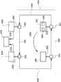
图1示出了根据本发明的光刻系统的第一实施例。Fig. 1 shows a first embodiment of a lithography system according to the invention.
图2示出了根据本发明的光刻系统的第二实施例的反馈控制系统和存储系统的细节。Fig. 2 shows details of a feedback control system and a storage system of a second embodiment of a lithographic system according to the present invention.
图3示出了根据本发明的光刻系统的第三实施例的反馈控制系统和存储系统的细节。Fig. 3 shows details of a feedback control system and a storage system of a third embodiment of a lithography system according to the present invention.
图4示意性示出了在根据本发明的光刻系统中用于处理目标的不同步骤和模块。Fig. 4 schematically shows the different steps and modules for processing an object in a lithography system according to the invention.
具体实施方式Detailed ways
图1中示出了根据本发明的光刻系统的实施例。光刻系统1包括光学组件(optical column)10,所述光学组件10包括发射带电粒子束2的带电粒子束源11。带电粒子束2在入射在孔阵列(aperture arrary)14上之前,穿过双八极(double octopole)12和准直透镜13。孔阵列14将带电粒子束2分成被聚光阵列15会聚的大量带电粒子束流(charged particlebeamlet)3。在流抑制器阵列16处,这些不同的束流中的一些被抑制,即,流4a被偏转使得它们稍后沿着它们的轨迹遇到流阻器阵列17而不是通过流阻器阵列17中的孔。没有被抑制的束流4b然后通过偏转器单元18,所述偏转器阵列18适于提供束流沿X和Y方向的扫描偏转。在它们的轨迹的端部,束流4b通过透镜阵列19,所述透镜阵列19适于将束流聚焦至由目标载板31支撑的目标30的表面上。目标载板31包括用于支撑目标30的基本平坦的表面32以及与目标30基本持平的上翘边沿33并且包括反射材料。致动器40适于根据来自控制单元60的控制信号相对于光学组件10沿着X和/或Y方向移动目标载板31和其上的目标30。在目标30的图案化过程中,目标载板31和目标30由致动器40在光学组件10下移动,从而使得未被阻止的流4b被机械地扫描至目标上的不同位置。测量系统50基本上连续地测量光刻系统1内的目标30的位置,优选相对于光学组件10的位置。在所示的实施例中,测量系统50包括干涉仪50,所述干涉仪50向目标载板31的反射表面33上发射测量光束51并且测量其反射以确定光刻系统1内的目标30的位置。通过单向连接80将测量的位置发送至控制单元60,控制单元60基于光刻系统1内目标30的期望的位置和测量位置之间的差来更新发送至致动器的控制信号。通过单向连接81将更新后的控制信号发送至致动器40。An embodiment of a lithography system according to the invention is shown in FIG. 1 . The lithographic system 1 comprises an
致动器40,干涉仪50和控制单元60一起构成反馈控制系统90,所述反馈控制系统基本上连续地测量并且更新光刻系统1内目标30的位置。在所示实施例中,反馈控制系统90内的通过测量系统50进行的位置测量和将更新后的控制信号发送至致动器40之间的最大延迟λ1至多为200ms,并且通过测量系统50进行的位置的测量或采样的频率至少在5到10kHz的数量级。通常,每个位置测量包括至少512比特的数据,使得每秒产生至少2.56MB的位置数据。The
除了控制致动器40,控制单元60还经由单向连接82将测量的位置和/或处理后的测量位置传送至储存系统70中的接收缓存器71。为了保证反馈控制系统90可连续不间断地操作,通过仅在反馈控制系统90和储存系统70之间设置单向连接来保证没有数据或信号从储存系统70发送到反馈控制系统90。In addition to controlling the
接收缓存器71具有存储多个测量的足够容量,例如,存储在20ms时间段内得到的所有位置测量数据。在所示的实施例中,接收缓存器70能够以与通过测量系统50测量位置数据的速率相同或更高的速率接收数据。当接收缓存器71存满时,不再接受来自反馈控制系统90的数据并且从反馈控制系统90传送至接收缓存器50的任何数据都被丢弃。The receive
存储系统还包括存储单元72,存储单元72的容量足够存储使用光刻系统从开始处理晶片或一批晶片到结束所需的至少整个时间段期间的测量的位置数据。所需的存储容量C可计算成C=T*R,其中,T为从开始处理晶片或一批晶片到结束所需的以秒为单位的时间,而R为测量系统每秒产生的数据量。例如,当从开始处理晶片到结束所需的时间是60天(即,5,184,000秒),并且每秒产生的测量的位置数据量为2.56MB时,那么所需要的存储容量是5,184,000s*2.56MB/s=13,271,040MB=13.27104TB。在接收缓存器71内接收位置数据和在存储单元72中存储所述数据之间的延迟比反馈控制环90的最大延迟λ1至少大一个数量级。接收缓存器71包括具有低延迟的相对小的内存,并且存储单元72包括相对大但具有更高平均延迟的较便宜内存。The storage system also includes a
图2示意性示出了在根据本发明的用在光刻系统101的另一个实施例中的存储系统170和反馈控制系统190。光刻系统101适用于使用从光学组件102投射至目标130上的一个或多个光束对目标130进行图案化,其中,所述图案可使用刻线或掩模形成,或通过使用调制多个光束的光束调制器形成。反馈控制系统190包括晶片定位系统110,晶片定位系统110包括致动器140,所述致动器140适于将目标,即,晶片在光刻系统中位移,尤其是平行于将要被光刻系统曝光的目标所横跨的平面。反馈控制系统190还包括测量系统150,所述测量系统适于基本连续地测量光刻系统内目标的位置。晶片定位系统110还包括基于测量的位置控制致动器140的控制单元160。环191表示测量系统150和晶片定位系统110之间的信息交换;由测量系统测量的目标位置被反传回晶片定位系统160,晶片定位系统160相应地基于测量结果调整系统内目标的位置。反馈控制系统190在所谓的实时约束的状态下操作。这意味着为了反馈控制系统能够操作,必须满足的条件是:晶片定位系统110的控制单元160在加上或减去预定的误差余量的预定固定时间点接收来自测量系统的140的每个位置测量,并且控制单元160在加上或减去预定的误差余量的预定固定时间点基于此提供给致动器140控制信号。如果这些条件中的一个不能满足,目标的定位被认为失败。例如,当由控制单元160接收的目标曝光过程中的位置测量比需要的晚时,控制系统将不能够及时控制致动器140以校正目标位置的任何误差并且曝光光束将在错误的位置照射在目标上。尽管反馈控制系统190必须在严格的实时约束内操作,但存储系统170不必在这种约束下操作,或至少在相对不严格的实时约束下工作。Fig. 2 schematically shows a
测量系统150经由第一单向连接180连接至存储系统170的交换机173的第一输入。晶片定位系统110经由第二单向连接182连接至交换机173的第二输入。单向连接180、182都是包括光纤以太网电缆的网络连接。使用用户数据报协议(UDP)通过这些连接将数据从晶片定位系统110和测量系统150发送至交换机173,但也可使用其它适用于单程通信的传输协议。分别连接至单向连接180,182的交换机173的第一和第二输入,每个都具有100Mb/s的最大数据速率。交换机包括连接至从交换机到接收缓存器171的连接174的输出,具有1Gb/s的最大数据速率,使得交换机的吞吐量不受其输出的数据速率限制。以5KHz的频率测量和校正位置,并且反馈控制环的延迟λ1小于200微秒,而在接收缓存器171内接收数据和在存储单元172内存储数据之间的平均延迟λ2是2100微秒。The
图3示意性示出了根据本发明的光刻系统的另一个实施例的细节,包括存储系统270,反馈控制系统290,测量计算机230和晶片定位计算机220。反馈控制系统290包括测量系统250,适于测量光刻系统内晶片的位置,以及晶片定位系统210,适于对光刻系统内的晶片进行定位。反馈控制系统290还包括由网络装置251、211、221、231和单向连接201、202、203、204形成的网络。网络装置251、211、221、231分别经由单向连接201、202、203、204将测量系统250,晶片定位系统210,晶片定位计算机220和测量控制计算机230连接至网络。测量计算机230适于将基本的控制数据发送至测量单元,例如,用于开始其校准。晶片定位计算机220为晶片定位系统210及时提供与目标的期望的位置有关的数据。在任何时间控制单元260控制致动器与校正期望的位置和测量的位置之间的偏差。FIG. 3 schematically shows details of another embodiment of a lithography system according to the present invention, including a
连接201、202、203、204包括光纤以太网电缆。从任何网络装置通过连接201、202、203、204发出的数据在网络内游走直到它到达数据最初产生的网络装置。因此,由测量系统250测量的位置数据被从网络装置251分别发送至网络装置211、221、231,从而使得网络中的所有网络装置接收相同的信息。箭头205表示当测量目标的物理位置时,关于由致动器的控制引起的目标的实际位置的改变的信息对测量系统250是可用的。换言之,测量系统250不依赖单向网络连接201、202、203或204得到光刻系统内目标的位置的测量。
在将数据发送至网络中的下一个目的地之前,每个网络装置211、221、231、251将传送给自己的本地拷贝数据存储到本地内存中。在单向连接201、202、203、204上传送的任何数据因此可通过从网络装置231或网络装置221的本地内存读出该数据的方式从反馈控制环290的外部读取,并且从网络装置231或网络装置221中任何一个读取数据的操作不改变反馈控制环290的测量位置和基于所述测量的位置将控制信号发送至致动器240之间的延迟。Each
存储系统270,如在本文所述包括接收缓存器和存储单元,分别经由单向连接233和223连接至测量计算机230和晶片控制计算机220,从而使得存储系统270操作中的任何故障或拖延都不会影响反馈控制系统290、测量计算机230和晶片定位计算机220。在存储系统270中的接收缓存器中接收数据和在存储系统270中的存储单元中存储数据之间的平均延迟比反馈控制系统290的测量目标的位置和基于所述测量的位置将控制信号发送至致动器之间延迟大三个数量级。
反馈控制系统290在严格的实时要求下操作,而测量计算机230及其存储系统270至少在较不严格的实时要求下操作。
图4示意性示出了用于处理目标的生产线,包括涂覆设备402、根据本发明的光刻系统403、显影设备404、检查设备405和蚀刻设备407,以上所有设备都可以接收来自主控单元401的控制数据402b、403b、404b、405b、407b,并且可将反馈数据402a、403a、404a、405a、407a传送至主控单元401。所述生产线还包括用于在处理过程中从已经被丢弃的目标上剥离抗蚀剂的剥离设备(stripping appratus)406。Figure 4 schematically shows a production line for processing objects, including a coating device 402, a photolithography system 403 according to the present invention, a developing device 404, an inspection device 405 and an etching device 407, all of which can receive information from the main control The control data 402b, 403b, 404b, 405b, 407b of the unit 401, and the feedback data 402a, 403a, 404a, 405a, 407a can be transmitted to the main control unit 401. The production line also includes a stripping appratus 406 for stripping resist from objects that have been discarded during processing.
处理从目标开始,在该情况下为晶片410。目标被插入到涂覆设备402中,涂覆设备402将抗蚀剂应用至晶片的曝光表面。接着,涂覆后的晶片被插入进光刻系统403,所述光刻系统是根据本发明的光刻系统。如上文所述,光刻系统403包括反馈控制系统和存储系统。由于光刻系统的反馈控制系统基本独立于存储系统工作,所以存储的反馈数据可从存储系统读出并且被传送至主控单元而不影响反馈控制系统的操作。Processing begins with a target, in this case a wafer 410 . The target is inserted into coating apparatus 402, which applies resist to the exposed surface of the wafer. Next, the coated wafer is inserted into a photolithography system 403, which is a photolithography system according to the present invention. As described above, the lithography system 403 includes a feedback control system and a storage system. Since the feedback control system of the lithography system works substantially independently of the storage system, stored feedback data can be read from the storage system and transferred to the main control unit without affecting the operation of the feedback control system.
接着,曝光后的晶片被传送至抗蚀剂被显影的显影设备404。在曝光没有在预定的误差余量的过程中定位的情况下,抗蚀剂没有被显影而是丢弃晶片并将所述晶片传送至剥离设备406。剥离设备406适于从晶片剥离抗蚀剂,从而使得同一晶片通过涂覆设备402再次涂覆而重新使用。在晶片的显影过程中确定了错误的情况下,晶片也被传送至剥离设备406。Next, the exposed wafer is transferred to a developing device 404 where the resist is developed. In the event that the exposure is not positioned within a predetermined margin of error, the resist is not developed but the wafer is discarded and transferred to the stripping apparatus 406 . The stripping device 406 is adapted to strip the resist from the wafer so that the same wafer is re-coated by the coating device 402 for reuse. The wafer is also transferred to the stripping apparatus 406 in the event that an error is determined during the development of the wafer.
在加工过程中基本没检测到错误的情况下,在检查设备405处检查晶片。该设备使用扫描电子显微镜等检查抗蚀剂中的曝光的特征的尺寸是否符合要求。例如,可测量特征的线宽。如果抗蚀剂中被检查的特征不符合要求,那么晶片被丢弃并且被传送至剥离设备406以从晶片上剥离抗蚀剂并且准备将晶片重新使用。In the event that substantially no errors are detected during processing, the wafer is inspected at inspection facility 405 . This equipment uses a scanning electron microscope or the like to check that the exposed features in the resist are sized as required. For example, you can measure the line width of a feature. If the features inspected in the resist are not satisfactory, the wafer is discarded and sent to stripping equipment 406 to strip the resist from the wafer and prepare the wafer for reuse.
如果曝光的图案符合要求那么晶片被传送至蚀刻设备407并且被蚀刻或化学机械抛光。If the exposed pattern is satisfactory then the wafer is transferred to the etch apparatus 407 and etched or chemical mechanically polished.
通常,从晶片切割得到的集成电路包括多个层并且晶片被引导通过涂覆设备402、光刻系统405、显影设备404、检查设备405和蚀刻设备407相应的次数以形成这些层。因此在从开始处理目标到结束的过程中,大量的位置数据是可用的,这些位置数据至少必须在目标被处理时被存储。在目标处理步骤中的任何一个处理中发生错误的情况下,位置数据可帮助追溯错误的起源。此外,可将位置数据用于改进工艺。Typically, integrated circuits cut from a wafer include multiple layers and the wafer is directed through coating equipment 402, lithography system 405, developing equipment 404, inspection equipment 405, and etching equipment 407 a corresponding number of times to form the layers. From the beginning to the end of processing an object, therefore, a large amount of position data is available which must be stored at least while the object is being processed. In the event that an error occurs in any one of the target processing steps, the location data can help trace the origin of the error. Furthermore, the location data can be used to improve the process.
综上,本发明涉及一种图案化目标的光刻系统,所述系统包括反馈控制系统,所述反馈控制系统包括用于移动目标的致动器、用于测量所述目标的位置的测量系统,和适于基于由所述测量系统测量的位置控制致动器的控制单元,所述反馈控制系统具有第一延迟,所述第一延迟为测量和基于所述测量控制致动器之间的最大延迟;存储系统,用于存储所述测量的位置,所述存储系统包括接收缓存器和存储单元,所述存储系统具有第二延迟,所述第二延迟为在接收缓存器中接收测量的位置和在存储单元中存储所述测量的位置之间的平均延迟,其中,所述第一延迟比所述第二延迟小至少一个数量级,所述反馈控制系统包括用于将测量的位置传送至存储系统的单向连接。In summary, the present invention relates to a lithography system for patterning a target, said system comprising a feedback control system comprising an actuator for moving the target, a measurement system for measuring the position of the target , and a control unit adapted to control the actuator based on the position measured by the measurement system, the feedback control system has a first delay between measuring and controlling the actuator based on the measurement a maximum delay; a storage system for storing the location of the measurements, the storage system comprising a receive buffer and a storage unit, the storage system having a second delay for receiving the measurements in the receive buffer an average delay between a position and storing said measured position in a storage unit, wherein said first delay is at least an order of magnitude less than said second delay, said feedback control system includes means for communicating the measured position to A one-way connection to a storage system.
应当理解的是,包括上述描述以示出优选实施例的操作并且目的不在于限制本发明的保护范围。从上面的讨论可知,对于本领域的技术人员来说大量的变形实施例是显而易见的,这些变形实施例同包括在本发明的精神和范围内。It should be understood that the above description is included to illustrate the operation of the preferred embodiment and is not intended to limit the scope of the invention. From the above discussion, numerous variations will be apparent to those skilled in the art which are within the spirit and scope of the invention.
Claims (27)
Translated fromChineseApplications Claiming Priority (3)
| Application Number | Priority Date | Filing Date | Title |
|---|---|---|---|
| US201161506581P | 2011-07-11 | 2011-07-11 | |
| US61/506,581 | 2011-07-11 | ||
| PCT/NL2012/050494WO2013028066A1 (en) | 2011-07-11 | 2012-07-10 | Lithography system and method for storing positional data of a target |
Publications (1)
| Publication Number | Publication Date |
|---|---|
| CN103782240Atrue CN103782240A (en) | 2014-05-07 |
Family
ID=46579303
Family Applications (1)
| Application Number | Title | Priority Date | Filing Date |
|---|---|---|---|
| CN201280044030.1APendingCN103782240A (en) | 2011-07-11 | 2012-07-10 | Lithographic system and method for storing positional data of an object |
Country Status (8)
| Country | Link |
|---|---|
| US (1) | US9009631B2 (en) |
| EP (1) | EP2732341B1 (en) |
| JP (1) | JP5805868B2 (en) |
| KR (1) | KR101611546B1 (en) |
| CN (1) | CN103782240A (en) |
| RU (1) | RU2583003C2 (en) |
| TW (1) | TWI497228B (en) |
| WO (1) | WO2013028066A1 (en) |
Cited By (2)
| Publication number | Priority date | Publication date | Assignee | Title |
|---|---|---|---|---|
| CN107608173A (en)* | 2017-11-07 | 2018-01-19 | 黄志群 | A kind of photochrome laser film processor for increasing photographic processing length |
| TWI765201B (en)* | 2018-12-28 | 2022-05-21 | 荷蘭商Asml荷蘭公司 | Charged-particle beam system and non-transitory computer readable medium |
Families Citing this family (2)
| Publication number | Priority date | Publication date | Assignee | Title |
|---|---|---|---|---|
| JP2017063101A (en) | 2015-09-24 | 2017-03-30 | 株式会社アドバンテスト | Exposure apparatus and exposure method |
| EP3893264A1 (en)* | 2020-04-06 | 2021-10-13 | ASML Netherlands B.V. | Charged particle assessment tool, inspection method |
Citations (7)
| Publication number | Priority date | Publication date | Assignee | Title |
|---|---|---|---|---|
| CN1601386A (en)* | 2003-09-22 | 2005-03-30 | Asml荷兰有限公司 | Lithographic apparatus, device manufacturing method, and device manufactured thereby |
| CN1839463A (en)* | 2003-07-09 | 2006-09-27 | 株式会社尼康 | Exposure apparatus and device manufacturing method |
| US20070182944A1 (en)* | 2006-02-07 | 2007-08-09 | Asml Netherlands B.V. | Lithographic apparatus and device manufacturing method |
| CN101080807A (en)* | 2005-07-01 | 2007-11-28 | 株式会社尼康 | Exposure apparatus, exposure method, device manufacturing method, and system |
| CN101464634A (en)* | 2007-12-19 | 2009-06-24 | Asml荷兰有限公司 | Lithographic apparatus, workbench system and its control method |
| EP2096494A1 (en)* | 2008-02-29 | 2009-09-02 | Canon Kabushiki Kaisha | Iterative learning for position control in an exposure apparatus |
| US20110029685A1 (en)* | 2009-07-31 | 2011-02-03 | Canon Kabushiki Kaisha | Information processing method and information processing apparatus for transmitting data generated by device manufacturing apparatus |
Family Cites Families (16)
| Publication number | Priority date | Publication date | Assignee | Title |
|---|---|---|---|---|
| JPH0616391B2 (en)* | 1984-07-13 | 1994-03-02 | 株式会社日立製作所 | Ion beam irradiation device |
| JPH0744221A (en)* | 1993-07-26 | 1995-02-14 | Komatsu Ltd | Dead time compensator in feedback controller |
| SE9800665D0 (en)* | 1998-03-02 | 1998-03-02 | Micronic Laser Systems Ab | Improved method for projection printing using a micromirror SLM |
| JP4722244B2 (en)* | 1998-07-14 | 2011-07-13 | ノバ・メジャリング・インストルメンツ・リミテッド | Apparatus for processing a substrate according to a predetermined photolithography process |
| US7230964B2 (en)* | 2001-04-09 | 2007-06-12 | Cymer, Inc. | Lithography laser with beam delivery and beam pointing control |
| KR100545294B1 (en)* | 2002-05-10 | 2006-01-24 | 에이에스엠엘 네델란즈 비.브이. | Lithographic apparatus, device manufacturing methods, performance measurement methods, calibration methods and computer programs |
| JP4017935B2 (en)* | 2002-07-30 | 2007-12-05 | 株式会社日立ハイテクノロジーズ | Multi-beam type electron beam drawing method and apparatus |
| JP4078150B2 (en) | 2002-08-22 | 2008-04-23 | 株式会社日立ハイテクノロジーズ | Semiconductor manufacturing equipment |
| US20040128918A1 (en) | 2002-11-06 | 2004-07-08 | Pai-Hsueh Yang | Control system and method for improving tracking accuracy of a stage through processing of information from previous operations |
| JP2006064570A (en)* | 2004-08-27 | 2006-03-09 | Nikon Corp | Interferometer system, signal processing method in interferometer system, and stage using the signal processing method |
| JP2006078262A (en) | 2004-09-08 | 2006-03-23 | Nikon Corp | Position detection apparatus, exposure apparatus, measurement system, and position detection method |
| US7327437B2 (en)* | 2004-12-07 | 2008-02-05 | Asml Netherlands B.V. | Lithographic apparatus and device manufacturing method |
| JP4984074B2 (en)* | 2005-05-31 | 2012-07-25 | 株式会社ニコン | Evaluation system and evaluation method |
| US20070239390A1 (en) | 2006-03-28 | 2007-10-11 | Yun Janet L | Low-power dissipation and monitoring method and apparatus in a measurement system |
| JP2010262000A (en)* | 2009-04-30 | 2010-11-18 | Orc Mfg Co Ltd | Drawing apparatus |
| US9507277B2 (en)* | 2010-07-30 | 2016-11-29 | Asml Netherlands B.V. | Lithographic apparatus and device manufacturing method |
- 2012
- 2012-07-10CNCN201280044030.1Apatent/CN103782240A/enactivePending
- 2012-07-10USUS13/545,896patent/US9009631B2/enactiveActive
- 2012-07-10RURU2014104561/28Apatent/RU2583003C2/enactive
- 2012-07-10EPEP12738653.0Apatent/EP2732341B1/enactiveActive
- 2012-07-10JPJP2014520155Apatent/JP5805868B2/enactiveActive
- 2012-07-10WOPCT/NL2012/050494patent/WO2013028066A1/enactiveApplication Filing
- 2012-07-10KRKR1020147003116Apatent/KR101611546B1/enactiveActive
- 2012-07-11TWTW101124896Apatent/TWI497228B/enactive
Patent Citations (7)
| Publication number | Priority date | Publication date | Assignee | Title |
|---|---|---|---|---|
| CN1839463A (en)* | 2003-07-09 | 2006-09-27 | 株式会社尼康 | Exposure apparatus and device manufacturing method |
| CN1601386A (en)* | 2003-09-22 | 2005-03-30 | Asml荷兰有限公司 | Lithographic apparatus, device manufacturing method, and device manufactured thereby |
| CN101080807A (en)* | 2005-07-01 | 2007-11-28 | 株式会社尼康 | Exposure apparatus, exposure method, device manufacturing method, and system |
| US20070182944A1 (en)* | 2006-02-07 | 2007-08-09 | Asml Netherlands B.V. | Lithographic apparatus and device manufacturing method |
| CN101464634A (en)* | 2007-12-19 | 2009-06-24 | Asml荷兰有限公司 | Lithographic apparatus, workbench system and its control method |
| EP2096494A1 (en)* | 2008-02-29 | 2009-09-02 | Canon Kabushiki Kaisha | Iterative learning for position control in an exposure apparatus |
| US20110029685A1 (en)* | 2009-07-31 | 2011-02-03 | Canon Kabushiki Kaisha | Information processing method and information processing apparatus for transmitting data generated by device manufacturing apparatus |
Cited By (3)
| Publication number | Priority date | Publication date | Assignee | Title |
|---|---|---|---|---|
| CN107608173A (en)* | 2017-11-07 | 2018-01-19 | 黄志群 | A kind of photochrome laser film processor for increasing photographic processing length |
| TWI765201B (en)* | 2018-12-28 | 2022-05-21 | 荷蘭商Asml荷蘭公司 | Charged-particle beam system and non-transitory computer readable medium |
| TWI853234B (en)* | 2018-12-28 | 2024-08-21 | 荷蘭商Asml荷蘭公司 | Charged-particle beam system and non-transitory computer readable medium |
Also Published As
| Publication number | Publication date |
|---|---|
| JP5805868B2 (en) | 2015-11-10 |
| RU2014104561A (en) | 2015-08-20 |
| US9009631B2 (en) | 2015-04-14 |
| TW201310174A (en) | 2013-03-01 |
| US20130016327A1 (en) | 2013-01-17 |
| EP2732341A1 (en) | 2014-05-21 |
| JP2014521220A (en) | 2014-08-25 |
| RU2583003C2 (en) | 2016-04-27 |
| TWI497228B (en) | 2015-08-21 |
| KR101611546B1 (en) | 2016-04-12 |
| WO2013028066A1 (en) | 2013-02-28 |
| EP2732341B1 (en) | 2016-11-30 |
| KR20140050040A (en) | 2014-04-28 |
Similar Documents
| Publication | Publication Date | Title |
|---|---|---|
| US8502978B2 (en) | Surface position detecting apparatus, exposure apparatus, surface position detecting method, and device manufacturing method | |
| US8411249B2 (en) | Surface position detecting apparatus, exposure apparatus, surface position detecting method, and device manufacturing method | |
| US8223345B2 (en) | Surface position detecting apparatus, exposure apparatus, surface position detecting method, and device manufacturing method | |
| TW200928600A (en) | Method and system of driving movable body, method and device of forming pattern, exposure method and apparatus, and device manufacturing method | |
| JP3926805B2 (en) | Apparatus for transferring an object, method of use thereof, and lithographic projection apparatus including the transfer apparatus | |
| US9164371B2 (en) | Method of correcting defects in a reflection-type mask and mask-defect correction apparatus | |
| JPS6313329A (en) | Exposure method | |
| CN103782240A (en) | Lithographic system and method for storing positional data of an object | |
| KR101764169B1 (en) | Maskless exposure apparatus and method for getting spot beam position using the same | |
| JP6521223B2 (en) | Lithographic apparatus management method and apparatus, and exposure method and system | |
| WO1999066543A1 (en) | Position sensing method, position sensor, exposure method, exposure apparatus, and production process thereof, and device and device manufacturing method | |
| US9904170B2 (en) | Reticle transmittance measurement method, projection exposure method using the same, and projection exposure device | |
| CN110114727B (en) | Metrology tool and method of using the same | |
| JP5128065B2 (en) | Information processing apparatus, device manufacturing processing system, device manufacturing processing method, program | |
| JPS6047418A (en) | semiconductor exposure equipment | |
| JP2013175500A (en) | Exposure device and exposure method | |
| WO2002047132A1 (en) | X-ray projection exposure device, x-ray projection exposure method, and semiconductor device | |
| CN113495437A (en) | Exposure apparatus, pattern forming apparatus, and exposure method | |
| KR101450518B1 (en) | Electron beam lithography and method for adjusting focus thereof | |
| JP4332891B2 (en) | Position detection apparatus, position detection method, exposure method, and device manufacturing method | |
| JP3937883B2 (en) | Alignment method and alignment apparatus | |
| JP6465565B2 (en) | Exposure apparatus, alignment method, and device manufacturing method | |
| JP2006186254A (en) | Data structure and data processing method used in substrate processing apparatus, recording medium, and program | |
| KR20230131225A (en) | Fast uniformity drift correction | |
| TWI667458B (en) | Reticle transmittance measurement method, projection exposure device, and projection exposure method |
Legal Events
| Date | Code | Title | Description |
|---|---|---|---|
| C06 | Publication | ||
| PB01 | Publication | ||
| C10 | Entry into substantive examination | ||
| SE01 | Entry into force of request for substantive examination | ||
| C02 | Deemed withdrawal of patent application after publication (patent law 2001) | ||
| WD01 | Invention patent application deemed withdrawn after publication | Application publication date:20140507 |