CN103767759A - Medical grinding cutter - Google Patents
Medical grinding cutterDownload PDFInfo
- Publication number
- CN103767759A CN103767759ACN201410041760.7ACN201410041760ACN103767759ACN 103767759 ACN103767759 ACN 103767759ACN 201410041760 ACN201410041760 ACN 201410041760ACN 103767759 ACN103767759 ACN 103767759A
- Authority
- CN
- China
- Prior art keywords
- bistrique
- cutter pipe
- sheath
- grinding head
- grinding
- Prior art date
- Legal status (The legal status is an assumption and is not a legal conclusion. Google has not performed a legal analysis and makes no representation as to the accuracy of the status listed.)
- Granted
Links
Images


Classifications
- A—HUMAN NECESSITIES
- A61—MEDICAL OR VETERINARY SCIENCE; HYGIENE
- A61B—DIAGNOSIS; SURGERY; IDENTIFICATION
- A61B17/00—Surgical instruments, devices or methods
- A61B17/16—Instruments for performing osteoclasis; Drills or chisels for bones; Trepans
- A—HUMAN NECESSITIES
- A61—MEDICAL OR VETERINARY SCIENCE; HYGIENE
- A61B—DIAGNOSIS; SURGERY; IDENTIFICATION
- A61B17/00—Surgical instruments, devices or methods
- A61B17/16—Instruments for performing osteoclasis; Drills or chisels for bones; Trepans
- A61B2017/1602—Mills
Landscapes
- Health & Medical Sciences (AREA)
- Surgery (AREA)
- Life Sciences & Earth Sciences (AREA)
- Biomedical Technology (AREA)
- Medical Informatics (AREA)
- Orthopedic Medicine & Surgery (AREA)
- Oral & Maxillofacial Surgery (AREA)
- Engineering & Computer Science (AREA)
- Dentistry (AREA)
- Heart & Thoracic Surgery (AREA)
- Nuclear Medicine, Radiotherapy & Molecular Imaging (AREA)
- Molecular Biology (AREA)
- Animal Behavior & Ethology (AREA)
- General Health & Medical Sciences (AREA)
- Public Health (AREA)
- Veterinary Medicine (AREA)
- Surgical Instruments (AREA)
Abstract
Translated fromChineseDescription
Translated fromChinese技术领域technical field
本发明涉及一种医疗器械,特别涉及一种骨科外科手术用的医用磨削刀具。The invention relates to a medical device, in particular to a medical grinding tool for orthopedic surgery.
背景技术Background technique
在进行骨科手术过程中,有时需对体内骨组织进行磨削;在现有技术中,磨削一般采用动力手柄直接驱动磨头转动进行磨削。由于由动力手柄直接驱动磨头,且磨头伸入人体内部;对于深入形成较深的手术部位,对于磨头的控制较为困难;特别是对于磨削部位的不同,无法外力控制磨头改变磨削部位,使用实现不了灵活方便,手术效率较低。In the process of orthopedic surgery, it is sometimes necessary to grind the bone tissue in the body; in the prior art, the power handle is generally used to directly drive the grinding head to rotate for grinding. Since the grinding head is directly driven by the power handle, and the grinding head extends into the inside of the human body; it is difficult to control the grinding head for deep surgical sites; especially for different grinding parts, it is impossible to control the grinding head to change the grinding head by external force. Cut the position, use can not realize flexible and convenient, and operation efficiency is lower.
为了解决上述问题,出现了一种可弯曲磨头,通过控制磨头进行俯仰动作,以适应磨削部位的改变;该结构的磨头采用万向节进行连接传动,结构以及制造工艺复杂,并且增加了刀具的半径,而骨科的上述手术一般则要求磨削刀具整体外径较小,否则刀具则无法到达手术部位或者手术过程中发生运动干扰。同时,该结构中,磨头与内刀管之间为了实现俯仰运动和转动传动的同时进行,采用万向头的连接结构,结构复杂且控制不稳定;并且该结构只具有俯仰动作,无法实现圆周方向磨削部位改变后的适应性操作,只有将刀具和驱动手柄整体转向,使用非常不便;并且,其驱动俯仰的驱动件也较为原始,影响刀具的紧凑性。In order to solve the above problems, a bendable grinding head has appeared, which can adapt to the change of the grinding part by controlling the pitching movement of the grinding head; the grinding head of this structure uses a universal joint for connection and transmission, and the structure and manufacturing process are complex, and The radius of the tool is increased, and the above-mentioned operations in orthopedics generally require the overall outer diameter of the grinding tool to be small, otherwise the tool cannot reach the surgical site or motion interference occurs during the operation. At the same time, in this structure, in order to realize the simultaneous pitching motion and rotation transmission between the grinding head and the inner cutter tube, the connection structure of the universal head is used, the structure is complicated and the control is unstable; and this structure only has pitching motion, which cannot realize The adaptive operation after changing the grinding part in the circumferential direction is to turn the tool and the driving handle as a whole, which is very inconvenient to use; moreover, the driving parts for driving the pitching are relatively primitive, which affects the compactness of the tool.
因此,需要一种医用磨削刀具,在手术过程中,能够使磨头实现纵向和周向的位置调节,对于手术部位具有较好的适应性,具有较好的精确性,提高手术过程效率,缩短术后恢复周期,减轻患者的痛苦的同时降低治疗成本;并且整体可拆卸,结构简单,传动链短,易于稳定控制,提高手术的效率。Therefore, there is a need for a medical grinding tool, which can adjust the position of the grinding head in the longitudinal and circumferential directions during the operation, has better adaptability to the operation site, has better accuracy, and improves the efficiency of the operation process. Shorten the postoperative recovery period, reduce the pain of patients and reduce the cost of treatment; and the whole is detachable, simple in structure, short in transmission chain, easy to control stably, and improve the efficiency of surgery.
发明内容Contents of the invention
有鉴于此,本发明提供一种医用磨削刀具,在手术过程中,能够使磨头实现纵向和周向的位置调节,对于手术部位具有较好的适应性,具有较好的精确性,提高手术过程效率,缩短术后恢复周期,减轻患者的痛苦的同时降低治疗成本;并且整体可拆卸,结构简单,传动链短,易于稳定控制,提高手术的效率。In view of this, the present invention provides a medical grinding tool, which can adjust the longitudinal and circumferential position of the grinding head during the operation, has better adaptability to the surgical site, has better accuracy, and improves The efficiency of the operation process shortens the postoperative recovery period, reduces the pain of the patient and reduces the cost of treatment; and the whole is detachable, the structure is simple, the transmission chain is short, easy to control stably, and the efficiency of the operation is improved.
本发明的医用磨削刀具,包括刀管组件和安装于刀管组件前端的磨头,所述磨头以可被驱动俯仰和自转的方式设置,其特征在于:所述刀管组件包括外刀管和同轴转动配合内套于外刀管且与磨头传动配合的内刀管,所述磨头尾端在圆周方向传动的方式铰接于内刀管,所述内刀管至少位于其前端设有用于与磨头尾端铰接且能够传递扭矩的柔性传动段。The medical grinding tool of the present invention comprises a knife tube assembly and a grinding head mounted on the front end of the knife tube assembly, the grinding head is set in a manner that can be driven to pitch and rotate, and it is characterized in that: the knife tube assembly includes an outer knife The tube and the inner knife tube coaxially rotated and fitted inside the outer knife tube and matched with the grinding head transmission, the tail end of the grinding head is hinged to the inner knife tube in the way of driving in the circumferential direction, and the inner knife tube is at least located at its front end There is a flexible transmission section for hinged connection with the tail end of the grinding head and capable of transmitting torque.
进一步,所述磨头尾端形成端部开口的铰接槽,所述柔性传动段前端传动配合设有用于与铰接槽交接配合的轴形铰接部;Further, the tail end of the grinding head forms an open-ended hinged groove, and the front end of the flexible transmission section is equipped with a shaft-shaped hinged part for handover and cooperation with the hinged groove;
进一步,所述磨头尾端形成铰接槽,所述柔性传动段前端传动配合设有用于与铰接槽铰接配合的轴形铰接部,该轴形铰接部与柔性传动段形成T形结构;Further, the tail end of the grinding head forms an articulation groove, and the front end of the flexible transmission section is drivingly equipped with a shaft-shaped hinge part for hinged cooperation with the articulation groove, and the shaft-shaped hinge part forms a T-shaped structure with the flexible transmission section;
进一步,柔性传动段与轴形铰接部连接根部在T形平面上缩颈;Further, the root of the connection between the flexible transmission section and the shaft-shaped hinge part is necked down on a T-shaped plane;
进一步,所述磨头设有磨头柄,所述铰接槽位于磨头柄的尾端;所述外刀管前端单自由度铰接设有磨头安装鞘,所述磨头柄单自由度转动配合内套于磨头安装鞘,磨头的磨削刃向前延伸出磨头安装鞘;所述柔性传动段连接于内刀管前端,所述轴形铰接部一体成形于柔性传动段前端;Further, the grinding head is provided with a grinding head handle, and the hinge groove is located at the tail end of the grinding head handle; the front end of the outer knife tube is hinged with a grinding head installation sheath, and the grinding head handle rotates with a single degree of freedom Cooperate with the inner sleeve of the grinding head installation sheath, the grinding edge of the grinding head extends forward out of the grinding head installation sheath; the flexible transmission section is connected to the front end of the inner knife tube, and the shaft-shaped hinge part is integrally formed at the front end of the flexible transmission section;
进一步,所述外刀管可被驱动其沿圆周方向转动的方式设置,使磨头安装鞘以及磨头以可被驱动公转的方式设置;Further, the outer knife tube can be driven to rotate in the circumferential direction, so that the grinding head installation sheath and the grinding head can be driven to rotate;
进一步,还包括连接柄和驱动组件,所述驱动组件包括用于驱动磨头安装鞘俯仰运动的俯仰驱动组件和用于驱动外刀管沿圆周方向转动的方向驱动组件;Further, it also includes a connecting handle and a drive assembly, the drive assembly includes a pitch drive assembly for driving the grinding head installation sheath to pitch and a direction drive assembly for driving the outer knife tube to rotate in the circumferential direction;
所述俯仰驱动组件包括往复中间件和往复驱动件,所述往复中间件前端以可驱动磨头安装鞘俯仰运动的方式连接磨头安装鞘,往复中间件后端与往复驱动件至少在轴向可驱动配合,所述往复驱动件与连接柄以可轴向相对运动的方式配合;The pitch drive assembly includes a reciprocating intermediate piece and a reciprocating driving piece. The front end of the reciprocating middle piece is connected to the grinding head installation sheath in a manner that can drive the grinding head installation sheath to pitch. The rear end of the reciprocating middle piece and the reciprocating driving piece are at least axially Driveable fit, the reciprocating drive part is matched with the connecting handle in a manner that can move relative to the axial direction;
所述方向驱动组件包括与磨削刀具的外刀管同轴固定的连接套和在圆周方向固定轴向可滑动外套于连接套的驱动套,所述驱动套沿轴向滑动可与连接柄啮合或分离实现周向限位或释放;The direction drive assembly includes a connecting sleeve fixed coaxially with the outer cutter tube of the grinding tool and a driving sleeve fixed axially and slidably over the connecting sleeve in the circumferential direction, and the driving sleeve can slide axially and engage with the connecting handle Or separation to achieve circumferential limit or release;
进一步,所述驱动套设有向后的预紧力且该预紧力使得驱动套与连接柄前端靠紧并周向啮合;所述往复中间件尾端轴向固定连接有过渡套,所述过渡套外圆设有径向驱动杆,该径向驱动杆与往复驱动件单自由度转动配合;所述往复驱动件为设有内螺纹的往复驱动套,其内螺纹与连接柄设有的外螺纹配合;所述驱动套后段设有缩颈,往复驱动套前段外套于驱动套的缩颈外圆,后段外套于连接柄。Further, the drive sleeve is provided with a backward pre-tightening force, and the pre-tightening force makes the drive sleeve and the front end of the connecting handle close together and engaged in the circumferential direction; the tail end of the reciprocating intermediate piece is axially fixedly connected with a transition sleeve, and the The outer circle of the transition sleeve is provided with a radial drive rod, and the radial drive rod cooperates with the reciprocating drive part in a single degree of freedom; Cooperating with external threads; the rear section of the drive sleeve is provided with a constricted neck, the front section of the reciprocating drive sleeve is covered with the necked outer circle of the drive sleeve, and the rear section is covered with the connecting handle.
本发明还公开了一种医用磨削刀具,包括刀管组件和安装于刀管组件前端的磨头,所述磨头以可被驱动俯仰和自转的方式设置,所述刀管组件包括外刀管和同轴转动配合内套于外刀管且与磨头传动配合的内刀管,所述外刀管前端单自由度铰接设有磨头安装鞘,磨削刀具的磨头设有磨头柄,磨头柄单自由度转动配合设有限位环,磨头柄通过该限位环以可轴向限位的方式内套于磨头安装鞘。The invention also discloses a medical grinding tool, which includes a knife tube assembly and a grinding head mounted on the front end of the knife tube assembly, the grinding head is set in a manner that can be driven to pitch and rotate, and the knife tube assembly includes an outer knife The tube and the inner knife tube coaxially rotated and fitted inside the outer knife tube and matched with the grinding head. The single-degree-of-freedom rotation of the grinding head handle is fitted with a limit ring, through which the grinding head handle is sleeved in the grinding head installation sheath in an axially limited manner.
进一步,所述磨头安装鞘包括外套和内套于外套的内套,所述限位环径向对称设有两个限位凸,磨头柄外圆设有用于使限位环卡入且具有径向活动余量的环形限位槽,所述内套设有两个径向对称的轴向开口槽,所述外套设有径向贯通的限位通孔且外套为具有轴向开口的开口套;所述磨头柄内套于内套中,限位环的两个限位凸起沿轴向开口槽卡入且其中一个限位凸起嵌入限位通孔内,另一个限位凸起则抵住外套内壁。Further, the grinding head installation sheath includes an outer sleeve and an inner sleeve which is sleeved on the outer sleeve, the limiting ring is radially symmetrically provided with two limiting projections, and the outer circle of the grinding head handle is provided with a ring for snapping in and An annular limiting groove with a radial movable margin, the inner sleeve is provided with two radially symmetrical axial opening grooves, the outer sleeve is provided with a radially penetrating limiting through hole and the outer sleeve is an axial opening Open sleeve; the grinding head handle is set inside the inner sleeve, and the two limit protrusions of the limit ring are snapped into the axial open groove, and one of the limit protrusions is embedded in the limit through hole, and the other limit The protrusion is against the inner wall of the coat.
本发明还公开了一种医用磨削刀具,包括刀管组件和安装于刀管组件前端的磨头,所述磨头以可被驱动俯仰和自转的方式设置,所述刀管组件包括外刀管和同轴转动配合内套于外刀管且与磨头传动配合的内刀管;所述外刀管前端单自由度铰接设有磨头安装鞘,磨削刀具的磨头沿圆周方向转动配合安装于磨头安装鞘,磨头的磨削刃向前延伸出磨头安装鞘;磨头安装鞘设有用于驱动其在铰接转动方向上俯仰运动的往复中间件,所述往复中间件至少在磨头安装鞘俯仰运动方向上具有活动余量。The invention also discloses a medical grinding tool, which includes a knife tube assembly and a grinding head mounted on the front end of the knife tube assembly, the grinding head is set in a manner that can be driven to pitch and rotate, and the knife tube assembly includes an outer knife The tube and the inner knife tube coaxially rotated and fitted inside the outer knife tube and matched with the grinding head; the front end of the outer knife tube is hinged with a single degree of freedom and equipped with a grinding head installation sheath, and the grinding head of the grinding tool rotates in the circumferential direction Cooperate with the mounting sheath of the grinding head, the grinding edge of the grinding head extends out of the mounting sheath of the grinding head; There is a margin of activity in the pitching direction of the grinding head installation sheath.
进一步,往复中间件为位于内刀管和外刀管之间的中间管,所述中间管与内刀管和外刀管之间均具有径向活动余量,该径向活动余量用于适应在驱动磨头安装鞘俯仰运动时中间管产生的径向位移;所述中间管前端向前延伸形成俯仰铰接段用于与磨头安装鞘铰接,所述俯仰铰接段为刚性。Further, the reciprocating intermediate piece is an intermediate tube located between the inner cutter tube and the outer cutter tube, and there is a radial movable margin between the intermediate tube and the inner cutter tube and the outer cutter tube, and the radial movable margin is used for To adapt to the radial displacement of the intermediate pipe when the grinding head installation sheath is driven to pitch; the front end of the intermediate pipe extends forward to form a pitch hinge section for hinged connection with the grinding head installation sheath, and the pitch hinge section is rigid.
本发明还公开了一种医用磨削刀具,包括刀管组件和安装于刀管组件前端的磨头,所述磨头以可被驱动俯仰和自转的方式设置,所述刀管组件包括外刀管和同轴转动配合内套于外刀管且与磨头传动配合的内刀管,外刀管前端设有用于安装磨头并用于带动磨头俯仰运动的磨头安装鞘,所述磨头安装鞘后端与外刀管前端以铰接头和铰接槽相互嵌入的方式形成单自由度铰接结构,外刀管用于与磨头安装鞘铰接的部位加厚处理。The invention also discloses a medical grinding tool, which includes a knife tube assembly and a grinding head mounted on the front end of the knife tube assembly, the grinding head is set in a manner that can be driven to pitch and rotate, and the knife tube assembly includes an outer knife The tube and the inner knife tube coaxially rotated and fitted inside the outer knife tube and matched with the grinding head transmission. The front end of the outer knife tube is provided with a grinding head installation sheath for installing the grinding head and driving the grinding head to pitch. The rear end of the installation sheath and the front end of the outer knife tube form a single-degree-of-freedom hinged structure in a manner of mutual embedding of the hinge head and the hinge groove, and the outer knife tube is used for thickening the part hinged with the grinding head installation sheath.
进一步,所述外刀管用于与磨头安装鞘铰接的部位为外刀管前端固定连接设有外刀管铰接段,外刀管铰接段前端面径向相对形成两个弧形铰接头,磨头安装鞘的尾端面径向相对形成两个用于使两个弧形铰接头对应嵌入并与其形成单自由度铰接结构的弧形铰接槽;所述外刀管铰接段位于两个弧形铰接头之间形成用于通过内刀管的通道。Further, the part where the outer knife tube is used to be hinged with the grinding head installation sheath is fixedly connected to the front end of the outer knife tube to be provided with an outer knife tube hinged section, and the front end faces of the outer knife tube hinged section are radially opposite to form two arc-shaped hinged joints. The tail end surface of the head mounting sheath is radially opposite to form two arc-shaped hinge grooves for correspondingly embedding the two arc-shaped hinge heads and forming a single-degree-of-freedom hinge structure; A channel for passing the inner knife tube is formed between the heads.
本发明的有益效果:本发明的医用磨削刀具,采用直接的铰接结构进行传递内刀管与磨头之间的传动,并且可进行俯仰运动,利用柔性传动结构补偿由于俯仰并传动导致的轴线偏离,传动结构简单,传动链较短,利于稳定控制,从而提高手术效率;并且采用可将磨头进行俯仰和周向位置均可以调节的结构,实现了磨头的万向方位调节,在手术过程中,能够使磨头根据手术方位的改变实现纵向和周向的位置调节,对于手术部位具有较好的适应性,具有较好的精确性,提高手术过程效率,缩短术后恢复周期,减轻患者的痛苦的同时降低治疗成本。Beneficial effects of the present invention: the medical grinding tool of the present invention adopts a direct hinge structure to transmit the transmission between the inner knife tube and the grinding head, and can perform pitching motion, and uses a flexible transmission structure to compensate the axis caused by pitching and transmission Deviation, the transmission structure is simple, the transmission chain is short, which is conducive to stable control, thereby improving the efficiency of surgery; and the structure that can adjust the pitch and circumferential position of the grinding head realizes the universal azimuth adjustment of the grinding head. During the process, the grinding head can be adjusted longitudinally and circumferentially according to the change of the surgical orientation, which has better adaptability to the surgical site, better accuracy, improves the efficiency of the surgical process, shortens the postoperative recovery period, and relieves the Reduce the cost of treatment while reducing the suffering of patients.
附图说明Description of drawings
下面结合附图和实施例对本发明作进一步描述。The present invention will be further described below in conjunction with the accompanying drawings and embodiments.
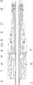
图1为本发明的结构示意图;Fig. 1 is a structural representation of the present invention;
图2为本发明前段剖视图;Fig. 2 is a sectional view of the front section of the present invention;
图3为本发明后段剖视图;Fig. 3 is a sectional view of the rear section of the present invention;
图4为图1A处放大图;Figure 4 is an enlarged view of Figure 1A;
图5为磨头结构图;Fig. 5 is a grinding head structural diagram;
图6为柔性传动段的结构图。Fig. 6 is a structural diagram of the flexible transmission section.
具体实施方式Detailed ways
图1为本发明的结构示意图,图2为本发明前段剖视图,图3为本发明后段剖视图,图4为图1A处放大图,图5为磨头结构图,图6为柔性传动段的结构图,如图所示:包括刀管组件和安装于刀管组件前端的磨头1,所述磨头1以可被驱动俯仰和自转的方式设置,所述刀管组件包括外刀管3和同轴转动配合内套于外刀管且与磨头传动配合的内刀管11,所述磨头1尾端在圆周方向传动的方式铰接于内刀管11,所述内刀管11至少位于其前端设有用于与磨头1尾端铰接且能够传递扭矩的柔性传动段13;俯仰是指相对于刀管组件的轴线呈一定的角度转动,自转是指磨头在驱动下进行磨削的转动,该磨头在使用时可调整为与刀管组件同轴,进入工作环境后根据需要调整俯仰位置,并进行磨削;俯仰后在进行磨削,传动则是通过柔性传动段适应传动轴线的变化。Fig. 1 is a schematic structural view of the present invention, Fig. 2 is a sectional view of the front section of the present invention, Fig. 3 is a sectional view of the rear section of the present invention, Fig. 4 is an enlarged view at Fig. 1A, Fig. 5 is a structural diagram of a grinding head, and Fig. 6 is a sectional view of a flexible transmission section Structural diagram, as shown in the figure: It includes a knife tube assembly and a
本实施例中,所述磨头1尾端形成端部开口的铰接槽1d,所述柔性传动段13前端传动配合设有用于与铰接槽1d交接配合的轴形铰接部13a;除了具有柔性传动段以适应俯仰后的驱动自转以外,铰接槽结构还与轴形铰接部之间具有活动余量,能较好的适应于俯仰后形成的长度差,以便顺畅传动,并且可将内刀管以及柔性传动段从外刀管内拔出,安装拆卸方便;In this embodiment, the tail end of the
本实施例中,轴形铰接部与柔性传动段形成T形结构,不但能够保证铰接结构的传动强度,还可在外刀管俯仰铰接处向内加厚以后顺利通过;当然,本结构的铰接部还能适用于铰接槽不是开口的结构。In this embodiment, the shaft-shaped hinge part and the flexible transmission section form a T-shaped structure, which can not only ensure the transmission strength of the hinge structure, but also pass through smoothly after the pitch hinge of the outer knife tube is thickened inward; of course, the hinge part of this structure It is also applicable to structures where the hinge groove is not an opening.
本实施例中,柔性传动段与轴形铰接部连接根部在T形平面上缩颈;本结构在轴形铰接部铰接如铰接槽后发生偏转可适应于铰接槽的结构,不与铰接槽的槽壁发生干涉。In this embodiment, the root of the connection between the flexible transmission section and the shaft-shaped hinge part is necked on the T-shaped plane; this structure deflects after the shaft-shaped hinge part is hinged such as a hinge groove, which can be adapted to the structure of the hinge groove, and does not match the structure of the hinge groove. The groove walls interfere.
本实施例中,所述磨头1设有磨头柄1a,所述铰接槽1d位于磨头柄1a的尾端;所述外刀管3前端单自由度铰接设有磨头安装鞘4,所述磨头柄1a单自由度转动配合内套于磨头安装鞘4,磨头1的磨削刃向前延伸出磨头安装鞘4,单自由度转动配合的配合方式可采用能够实现该结构的任何机械方式,包括轴向机械限位等等;采用磨头柄1a的结构,利于安装和装配,并且利于保证结构的紧凑性,适用于本领域,并利用磨头安装鞘4带动磨头1完成俯仰动作;所述柔性传动段连接于内刀管11前端,连接可采用螺纹连接或者卡接等等,具有较好的适应性,可根据需要更换柔性传动段,以保证刀具的长周期使用;所述轴形铰接部一体成形于柔性传动段前端;单自由度铰接指的是二者的相对运动只局限于铰接的转动方向,铰接的方式可采用现有的轴铰接结构,由于本结构更倾向于细小,因此,直接采用在一个部件上设置铰接槽,另一部件加工出与铰接槽配合的轴状结构或径向对称的球状结构等;如图所示,所述外刀管3前端面径向相对形成两个弧形铰接头3a,磨头安装鞘4的尾端面径向相对形成两个用于使两个弧形铰接头3a对应嵌入并与其形成单自由度铰接结构的弧形铰接槽4a;结构简单,加工方便,铰接转动灵活,且易于拆卸;该结构使得外刀管轴线与铰接轴线处于同一平面,运动灵活;In this embodiment, the grinding
如图所示,所述磨头柄1a与柔性传动段13铰接后可具有轴向的活动余量,形成了完全的开式铰接结构,即由轴形铰接部直接嵌入铰接槽形成,并可具有轴向的余量,从而使二者之间运动顺畅,使得内刀管11以及柔性传动段13能够随时抽出,方便清洗以及维护;本结构去除了现有技术的万向轴结构,实现了结构的紧凑和体积的减小,更适用于深度及狭小空间。As shown in the figure, after the grinding head handle 1a is hinged with the
本实施例中,所述外刀管3可被驱动其沿圆周方向转动的方式设置,使磨头安装鞘4以及磨头1以可被驱动公转的方式设置;公转是指整个磨头1绕刀管组件的轴线转动,以达到万向磨削的目的,即采用俯仰以及周向的两个自由度,组合形成多个方向的工作状态;该磨头在使用时可调整为与刀管组件同轴,进入工作环境后根据需要调整俯仰以及公转位置,并进行磨削。In this embodiment, the
本实施例中,还包括连接柄9和驱动组件,所述驱动组件包括用于驱动磨头安装鞘俯仰运动的俯仰驱动组件和用于驱动外刀管沿圆周方向转动的方向驱动组件;In this embodiment, it also includes a connecting
所述俯仰驱动组件包括往复中间件和往复驱动件,所述往复中间件前端以可驱动磨头安装鞘俯仰运动的方式连接磨头安装鞘,用于驱动磨头安装鞘4在俯仰铰接方向上转动,带动磨头实现俯仰运动;往复中间件后端与往复驱动件至少在轴向可驱动配合,所述往复驱动件与连接柄以可轴向相对运动的方式配合,用于驱动往复中间件往复运动,以实现磨头安装鞘的俯仰运动;所述往复驱动件与连接柄以可轴向相对运动的方式配合,可通过螺纹配合或者其他的往复运动且可随时定位的配合方式。The pitching drive assembly includes a reciprocating middle piece and a reciprocating driving piece. The front end of the reciprocating middle piece is connected to the grinding head installation sheath in a manner that can drive the grinding head installation sheath to move in pitch, and is used to drive the grinding
所述方向驱动组件包括与磨削刀具的外刀管同轴固定的连接套和在圆周方向固定轴向可滑动外套于连接套的驱动套7,外刀管3与连接套6之间采用焊接连接,连接套6与驱动套7之间可采用轴向的平键或者花键的配合方式实现,在此不再赘述;所述驱动套沿轴向滑动可与连接柄啮合或分离实现周向限位或释放;本结构中,可在连接柄9前端设置端面花键,同时,驱动套7尾端也设置有端面花键,当驱动套7在外力驱动轴向滑动时,可使两端面花键啮合或者分离,达到使驱动套7相对固定或可转动的状态;当两端面花键分离时,可手动驱动驱动套7转动并带动连接套6转动,从而带动外刀管3转动,使得磨头1实现公转,结合磨头1的自转以及俯仰运动,实现万向功能。The directional drive assembly includes a connecting sleeve fixed coaxially with the outer knife tube of the grinding tool and a
本实施例中,所述驱动套7设有向后的预紧力且该预紧力使得驱动套与连接柄前端靠紧并周向啮合,该预紧力可通过弹簧或者卡簧实现,利用预紧力实现啮合,避免出现误操作或者运行时出现脱挂问题;如图所示,驱动套7内圆形成弹簧腔,一柱状弹簧14外套于连接套6并两端分别顶住连接套外圆形成的外凸台和驱动套7内圆形成的内凸台;所述往复中间件尾端轴向固定连接有过渡套15,所述过渡套15外圆设有径向驱动杆15a,该径向驱动杆15a与往复驱动件单自由度转动配合,如图所示,通过与连接柄8螺纹配合的压套16将径向驱动杆15a压接轴向固定;所述往复驱动件8为设有内螺纹的往复驱动套,其内螺纹与连接柄8设有的外螺纹配合;所述驱动套7后段设有缩颈,往复驱动套前段外套于驱动套的缩颈外圆,后段外套于连接柄8;通过旋转往复驱动套并带动径向驱动杆15a往复运动,平稳而精确,避免现有技术中存在的顿挫感,同时,螺纹配合使得各个部件之间紧凑而完整性好;所述驱动套7后段设有缩颈,往复驱动套前段外套于驱动套7的缩颈外圆,往复驱动套前段内圆形成台阶,该台阶通过连接的压盖形成环形槽,如图所示,径向驱动杆15a嵌合于该环形槽内形成轴向固定周向可转动的配合结构,当然,径向驱动杆15a可以沿圆周方向设置多个,如图所示的两个对称设置也较为均匀的传递驱动力,由于径向驱动杆位于驱动套与连接柄9以及往复驱动套之间,因此,需要避开驱动套7与连接柄9之间的端面花键,以避免运动干扰;往复驱动套后段外套于连接柄9,如图所示,往复驱动套后段外套于连接柄并且螺纹配合,方便操作。In this embodiment, the driving
该医用磨削刀具尾部设有与动力连接的接头10,并与连接柄9通过连接柄9内表面须设有必要的支撑,如图所示的支撑过渡套17,前端外套于过渡套15,后段内套于密封过渡套18,为转动配合。密封过渡套18转动配合,设有必要的密封圈和滑动轴承等,在此不自爱赘述。The tail of the medical grinding tool is provided with a joint 10 connected to the power, and the connecting
本发明还公开了一种医用磨削刀具的具体实施方式,包括刀管组件和安装于刀管组件前端的磨头1,所述磨头以可被驱动俯仰和自转的方式设置,所述刀管组件包括外刀管3和同轴转动配合内套于外刀管3且与磨头1传动配合的内刀管11,所述外刀管前端单自由度铰接设有磨头安装鞘4,磨削刀具的磨头1设有磨头柄1a,磨头柄1a单自由度转动配合设有限位环1c,磨头柄1a通过该限位环1c以可轴向限位的方式内套于磨头安装鞘4.结构简单,拆装容易,可通过限位环1c直接嵌入磨头安装鞘4内,实现轴向限位;单自由度转动配合的方式可较多的采用嵌入环形槽的方式。The invention also discloses a specific embodiment of a medical grinding tool, which includes a knife tube assembly and a grinding
本实施例中,所述磨头安装鞘4包括外套和内套于外套的内套4c,所述限位环1c径向对称设有两个限位凸1c1、1c2,磨头柄1a外圆设有用于使限位环1c卡入且具有径向活动余量的环形限位槽1b,单自由度转动配合是通过限位环1c嵌入的环形限位槽1b实现;所述内套4c设有两个径向对称的轴向开口槽4c1、4c2,所述外套设有径向贯通的限位通孔4b且外套为具有轴向开口的开口套;所述磨头柄1a内套于内套4c中,限位环1c的两个限位凸起1c1、1c2沿内套4c的轴向开口槽4c1、4c2卡入且其中一个限位凸起1c1嵌入限位通孔内,另一个限位凸1c2起则抵住外套内壁,由于磨头安装鞘4的外套具有轴向开口,因而具有径向的弹性,可用于固定限位环1c;如图所示,外套的轴向开口与限位通孔成45°分布于外套;安装时,将磨头柄1a与限位环1c一同内套入内套4c,两个限位凸1c1、1c2被径向限制压缩,当限位环滑到安装位,其中一个限位凸起1c1嵌入外套的限位通孔,实现轴向限位;拆卸时,将限位通孔4b内的限位凸起1c1沿径向下压,限位环1c(限位环为开口环,方便装入环形限位槽1b且利于变形)本身以及外套都会发生变形,该限位凸起1c1从限位通孔4b内径向向内脱出,可拆出磨头柄1a;如图所示,外套不但轴向开有开口,沿圆周方向还开有周向槽,该周向槽在前述轴向开口槽边缘具有开口,减小了安装和拆卸的难度。In this embodiment, the grinding
本实施例的医用磨削刀具与前述的技术方案可结合使用,以取得更好的效果。The medical grinding tool of this embodiment can be used in combination with the aforementioned technical solutions to achieve better results.
本发明还公开了一种医用磨削刀具,包括刀管组件和安装于刀管组件前端的磨头,所述磨头1以可被驱动俯仰和自转的方式设置,所述刀管组件包括外刀管3和同轴转动配合内套于外刀管3且与磨头1传动配合的内刀管11;所述外刀管3前端单自由度铰接设有磨头安装鞘4,磨削刀具的磨头1沿圆周方向转动配合安装于磨头安装鞘4,磨头1的磨削刃向前延伸出磨头安装鞘4;磨头安装鞘4设有用于驱动其在铰接转动方向上俯仰运动的往复中间件,所述往复中间件至少在磨头安装鞘俯仰运动方向上具有活动余量;以适应由于直接铰接后磨头安装鞘4俯仰运动导致的往复中间件的径向移动,避免发生干扰,结构简单实用。The invention also discloses a medical grinding tool, which includes a knife tube assembly and a grinding head installed at the front end of the knife tube assembly. The
本实施例中,往复中间件为位于内刀管11和外刀管3之间的中间管12,所述中间管12与内刀管11和外刀管3之间均具有径向活动余量,该径向活动余量用于适应在驱动磨头安装鞘4俯仰运动时中间管产生的径向位移;所述中间管12前端向前延伸形成俯仰铰接段5用于与磨头安装鞘铰接,所述俯仰铰接段5为刚性,使得中间管不但利用径向活动余量适应磨头安装鞘俯仰时较小的径向位移,俯仰铰接段的刚性结构能够较为顺畅的驱动磨头安装鞘的俯仰运动,结构简单紧凑,避免复杂结构导致的体积增大,保证手术的顺利进行;如图所示,俯仰铰接段5为刚性通过加厚实现,该加厚结构In this embodiment, the reciprocating intermediate piece is an
俯仰铰接段5形成一短节上,该短节与中间管固定连接,当然,也可以直接成形于中间管,并不影响本发明的发明目的。由于本具体实施方式可以与前述技术方案结合使用,因此,所述中间管12尾端轴向固定连接前述的过渡套15,所述过渡套15外圆设有径向驱动杆15a,本实施例中过渡套与中间管焊接连接,过渡套15与径向驱动杆15a一体成形;该径向驱动杆15a与往复驱动件单自由度转动配合,实现前后驱动,结构简单紧凑,拆装方便。The pitching
本发明还公开了一种医用磨削刀具具体实施方式,包括刀管组件和安装于刀管组件前端的磨头1,所述磨头1以可被驱动俯仰和自转的方式设置,所述刀管组件包括外刀管3和同轴转动配合内套于外刀管3且与磨头1传动配合的内刀管11,外刀管3前端设有用于安装磨头并用于带动磨头1俯仰运动的磨头安装鞘4,所述磨头安装鞘4后端与外刀管前端以铰接头和铰接槽相互嵌入的方式形成单自由度铰接结构,外刀管3用于与磨头安装鞘4铰接的部位加厚处理,本设计使铰链具有了足够的厚度,从而增加了强度,中间只留一个狭小的通道,该加厚处理结构利于在磨削过程中增加弯折部位承担较大的侧向弯矩,从而保证手术的顺利进行。The invention also discloses a specific embodiment of a medical grinding tool, which includes a knife tube assembly and a grinding
本实施例中,所述外刀管3用于与磨头安装鞘4铰接的部位为外刀管3前端固定连接设有外刀管铰接段3b,外刀管3铰接段可通过螺纹连接、焊接等连接方式,在此不再赘述;外刀管3铰接段前端面径向相对形成两个弧形铰接头3a,磨头安装鞘4的尾端面径向相对形成两个用于使两个弧形铰接头3a对应嵌入并与其形成单自由度铰接结构的弧形铰接槽4a;所述外刀管铰接段3b位于两个弧形铰接头3a之间形成用于通过内刀管的通道,所述外刀管铰接段的加厚处理在该通道内径向向内;内刀管(包括柔性传动段)头部的特定形状使其可以通过两个弧形铰接头之间的狭小的通道(由于加厚导致的通道狭小)后,避开两个弧形铰接头和前端磨头形成万向节,进行旋转驱动;该结构对于铰接头部位加厚处理并且采用外刀管铰接段3b和外刀管3的连接结构,不但增加了铰接处的强度,还方便安装。In this embodiment, the part of the outer knife tube 3 that is used to be hinged with the grinding head installation sheath 4 is fixedly connected to the front end of the outer knife tube 3 and is provided with an outer knife tube hinged section 3b, and the outer knife tube 3 hinged section can be connected by threads, Connection methods such as welding are not repeated here; the front end faces of the hinged section of the outer knife tube 3 are radially opposite to form two arc-shaped hinge joints 3a, and the tail end faces of the grinding head mounting sheath 4 are radially opposite to form two for making the two The arc-shaped hinge 3a is correspondingly embedded and forms an arc-shaped hinge groove 4a with a single-degree-of-freedom hinge structure; the outer knife tube hinge section 3b is located between the two arc-shaped hinges 3a to form a passage for passing through the inner knife tube, The thickening treatment of the hinged section of the outer knife tube is radially inward in the channel; the specific shape of the head of the inner knife tube (including the flexible transmission section) allows it to pass through the narrow channel between the two arc-shaped hinged joints ( After the channel is narrow due to thickening), avoid the two arc-shaped hinge joints and the front-end grinding head to form a universal joint for rotation drive; this structure thickens the hinge joint and uses the outer knife tube hinge section 3b and The connection structure of the outer knife tube 3 not only increases the strength of the hinge, but also facilitates installation.
以上使本发明中的具体实施方式独立形成技术方案的同时,所有技术方案均可以组合,共同实现本发明的目的,也就是,该结构可独立形成方案或者结合并应用于本发明的刀具中,在此不再赘述;While the above-mentioned specific embodiments in the present invention independently form technical solutions, all technical solutions can be combined to jointly achieve the purpose of the present invention, that is, the structure can independently form a solution or be combined and applied to the cutting tool of the present invention, I won't repeat them here;
最后说明的是,以上实施例仅用以说明本发明的技术方案而非限制,尽管参照较佳实施例对本发明进行了详细说明,本领域的普通技术人员应当理解,可以对本发明的技术方案进行修改或者等同替换,而不脱离本发明技术方案的宗旨和范围,其均应涵盖在本发明的权利要求范围当中。Finally, it is noted that the above embodiments are only used to illustrate the technical solutions of the present invention without limitation. Although the present invention has been described in detail with reference to the preferred embodiments, those of ordinary skill in the art should understand that the technical solutions of the present invention can be carried out Modifications or equivalent replacements without departing from the spirit and scope of the technical solution of the present invention shall be covered by the claims of the present invention.
Claims (14)
Priority Applications (13)
| Application Number | Priority Date | Filing Date | Title |
|---|---|---|---|
| CN201410041760.7ACN103767759B (en) | 2014-01-28 | 2014-01-28 | Medical grinding cutter |
| EP17179220.3AEP3260062B1 (en) | 2013-11-29 | 2014-09-26 | Lateral grinding drill with continuously variable angle and driving component thereof |
| EP17179219.5AEP3260061B1 (en) | 2013-11-29 | 2014-09-26 | Lateral grinding drill with continuously variable angle and driving component thereof |
| ES17179219TES2775187T3 (en) | 2013-11-29 | 2014-09-26 | Continuously variable angle side grinding cutter and drive component |
| KR1020157034145AKR101740976B1 (en) | 2013-11-29 | 2014-09-26 | Electrodeless variable angle sideways drill grinding head and drive components thereof |
| KR1020177012397AKR102050216B1 (en) | 2013-11-29 | 2014-09-26 | Electrodeless variable angle sideways drill grinding head and drive components thereof |
| KR1020177012399AKR102050221B1 (en) | 2013-11-29 | 2014-09-26 | Electrodeless variable angle sideways drill grinding head and drive components thereof |
| PCT/CN2014/087552WO2015078229A1 (en) | 2013-11-29 | 2014-09-26 | Electrodeless variable angle sideways drill grinding head and drive components thereof |
| US14/894,939US10178998B2 (en) | 2013-11-29 | 2014-09-26 | Lateral grinding drill with continuously variable angle and driving component thereof |
| EP14866116.8AEP3000417B1 (en) | 2013-11-29 | 2014-09-26 | Electrodeless variable angle sideways drill grinding head and drive components thereof |
| JP2016553696AJP6227159B2 (en) | 2013-11-29 | 2014-09-26 | Side grinding drill with continuously variable angle |
| JP2017110056AJP6303048B2 (en) | 2013-11-29 | 2017-06-02 | Side grinding drill with continuously variable angle |
| JP2017110065AJP6410876B2 (en) | 2013-11-29 | 2017-06-02 | Side grinding drill including continuously variable angle part and its driving parts |
Applications Claiming Priority (1)
| Application Number | Priority Date | Filing Date | Title |
|---|---|---|---|
| CN201410041760.7ACN103767759B (en) | 2014-01-28 | 2014-01-28 | Medical grinding cutter |
Publications (2)
| Publication Number | Publication Date |
|---|---|
| CN103767759Atrue CN103767759A (en) | 2014-05-07 |
| CN103767759B CN103767759B (en) | 2015-04-15 |
Family
ID=50560834
Family Applications (1)
| Application Number | Title | Priority Date | Filing Date |
|---|---|---|---|
| CN201410041760.7AActiveCN103767759B (en) | 2013-11-29 | 2014-01-28 | Medical grinding cutter |
Country Status (1)
| Country | Link |
|---|---|
| CN (1) | CN103767759B (en) |
Cited By (20)
| Publication number | Priority date | Publication date | Assignee | Title |
|---|---|---|---|---|
| CN104546063A (en)* | 2015-01-27 | 2015-04-29 | 范伟力 | Spine end plate processing grinding head and spine end plate processing device |
| WO2015078229A1 (en)* | 2013-11-29 | 2015-06-04 | 重庆西山科技有限公司 | Electrodeless variable angle sideways drill grinding head and drive components thereof |
| CN104688295A (en)* | 2015-01-14 | 2015-06-10 | 雷东 | Medical grinding power device with angle adjusting function |
| CN105030295A (en)* | 2015-06-30 | 2015-11-11 | 浙江天松医疗器械股份有限公司 | Bone tissue grinding tool for surgery |
| CN105411646A (en)* | 2015-11-30 | 2016-03-23 | 重庆西山科技股份有限公司 | Medical grinding tool capable of being laterally bent |
| CN105534573A (en)* | 2015-12-15 | 2016-05-04 | 宁波华科润生物科技有限公司 | Novel medical camber-adjustable tissue removing device |
| CN105726085A (en)* | 2016-04-18 | 2016-07-06 | 珠海维尔康生物科技有限公司 | Driving force transmission component and manufacturing method as well as bendable grinding head and medical grinding tool |
| CN105796153A (en)* | 2016-04-13 | 2016-07-27 | 成都格瑞思文化传播有限公司 | Novel osteotome |
| CN106238798A (en)* | 2014-05-26 | 2016-12-21 | 昆山科森科技股份有限公司 | Minimally Invasive Surgery aluminum pipe organisation of working |
| CN106725747A (en)* | 2016-12-30 | 2017-05-31 | 重庆西山科技股份有限公司 | Medical cutting device |
| CN107072673A (en)* | 2014-07-14 | 2017-08-18 | Kb医疗公司 | Anti-skidding operating theater instruments for preparing hole in bone tissue |
| CN109124726A (en)* | 2018-07-11 | 2019-01-04 | 芜湖帮许来诺医疗设备科技有限公司 | A kind of artery turnery interposers |
| CN109431572A (en)* | 2018-11-20 | 2019-03-08 | 宁波华科润生物科技有限公司 | A kind of medical deflectable bistrique |
| CN110811758A (en)* | 2019-11-27 | 2020-02-21 | 中南大学湘雅医院 | An adjustable medical grinder |
| CN111012436A (en)* | 2020-01-09 | 2020-04-17 | 博能华医疗器械(北京)有限公司 | Intervertebral foramen mirror down variable angle flat file grinding device |
| US10765438B2 (en) | 2014-07-14 | 2020-09-08 | KB Medical SA | Anti-skid surgical instrument for use in preparing holes in bone tissue |
| US11160562B2 (en) | 2020-01-09 | 2021-11-02 | Arthrex, Inc. | Assemblies for preparation of surgical sites |
| US11246604B2 (en) | 2019-10-02 | 2022-02-15 | Arthrex, Inc. | Reaming assemblies for preparation of surgical sites |
| WO2022148296A1 (en)* | 2021-01-11 | 2022-07-14 | 丰凯医疗器械(上海)有限公司 | Flexible transmission device |
| CN117854767A (en)* | 2023-12-18 | 2024-04-09 | 中核核电运行管理有限公司 | Nuclear power plant steam generator secondary side heat transfer pipe foreign matter cutting device |
Citations (7)
| Publication number | Priority date | Publication date | Assignee | Title |
|---|---|---|---|---|
| WO2001060232A2 (en)* | 2000-02-16 | 2001-08-23 | Axiamed, Inc. | Apparatus for forming curved axial bores through spinal vertebrae |
| US20050147478A1 (en)* | 2003-12-30 | 2005-07-07 | Greenberg Alex M. | Sleeved stop for a drill bit |
| US20050203527A1 (en)* | 2004-03-03 | 2005-09-15 | Scimed Life Systems, Inc. | Apparatus and methods for removing vertebral bone and disc tissue |
| CN201346224Y (en)* | 2009-01-19 | 2009-11-18 | 梁雄 | Reciprocating bone saw |
| CN102210604A (en)* | 2010-04-02 | 2011-10-12 | 北京市春立正达科技开发有限公司 | Medical grater |
| CN103200885A (en)* | 2010-11-03 | 2013-07-10 | 吉鲁斯恩特公司 | Surgical tool with sheath |
| CN203388927U (en)* | 2013-07-29 | 2014-01-15 | 重庆西山科技有限公司 | Joint surgery grinding knife |
- 2014
- 2014-01-28CNCN201410041760.7Apatent/CN103767759B/enactiveActive
Patent Citations (7)
| Publication number | Priority date | Publication date | Assignee | Title |
|---|---|---|---|---|
| WO2001060232A2 (en)* | 2000-02-16 | 2001-08-23 | Axiamed, Inc. | Apparatus for forming curved axial bores through spinal vertebrae |
| US20050147478A1 (en)* | 2003-12-30 | 2005-07-07 | Greenberg Alex M. | Sleeved stop for a drill bit |
| US20050203527A1 (en)* | 2004-03-03 | 2005-09-15 | Scimed Life Systems, Inc. | Apparatus and methods for removing vertebral bone and disc tissue |
| CN201346224Y (en)* | 2009-01-19 | 2009-11-18 | 梁雄 | Reciprocating bone saw |
| CN102210604A (en)* | 2010-04-02 | 2011-10-12 | 北京市春立正达科技开发有限公司 | Medical grater |
| CN103200885A (en)* | 2010-11-03 | 2013-07-10 | 吉鲁斯恩特公司 | Surgical tool with sheath |
| CN203388927U (en)* | 2013-07-29 | 2014-01-15 | 重庆西山科技有限公司 | Joint surgery grinding knife |
Cited By (29)
| Publication number | Priority date | Publication date | Assignee | Title |
|---|---|---|---|---|
| WO2015078229A1 (en)* | 2013-11-29 | 2015-06-04 | 重庆西山科技有限公司 | Electrodeless variable angle sideways drill grinding head and drive components thereof |
| CN106238798A (en)* | 2014-05-26 | 2016-12-21 | 昆山科森科技股份有限公司 | Minimally Invasive Surgery aluminum pipe organisation of working |
| US10945742B2 (en) | 2014-07-14 | 2021-03-16 | Globus Medical Inc. | Anti-skid surgical instrument for use in preparing holes in bone tissue |
| US11534179B2 (en) | 2014-07-14 | 2022-12-27 | Globus Medical, Inc. | Anti-skid surgical instrument for use in preparing holes in bone tissue |
| CN107072673A (en)* | 2014-07-14 | 2017-08-18 | Kb医疗公司 | Anti-skidding operating theater instruments for preparing hole in bone tissue |
| US10765438B2 (en) | 2014-07-14 | 2020-09-08 | KB Medical SA | Anti-skid surgical instrument for use in preparing holes in bone tissue |
| CN104688295A (en)* | 2015-01-14 | 2015-06-10 | 雷东 | Medical grinding power device with angle adjusting function |
| CN104546063A (en)* | 2015-01-27 | 2015-04-29 | 范伟力 | Spine end plate processing grinding head and spine end plate processing device |
| CN105030295A (en)* | 2015-06-30 | 2015-11-11 | 浙江天松医疗器械股份有限公司 | Bone tissue grinding tool for surgery |
| CN105411646A (en)* | 2015-11-30 | 2016-03-23 | 重庆西山科技股份有限公司 | Medical grinding tool capable of being laterally bent |
| WO2017092578A1 (en)* | 2015-11-30 | 2017-06-08 | 重庆西山科技股份有限公司 | Laterally bendable grinding knife for medical use |
| CN105411646B (en)* | 2015-11-30 | 2019-02-15 | 重庆西山科技股份有限公司 | Medical side bendable grinding tool |
| CN105534573A (en)* | 2015-12-15 | 2016-05-04 | 宁波华科润生物科技有限公司 | Novel medical camber-adjustable tissue removing device |
| CN105534573B (en)* | 2015-12-15 | 2019-03-05 | 宁波华科润生物科技有限公司 | A kind of medical adjustable bending tissue removal instrument |
| CN105796153A (en)* | 2016-04-13 | 2016-07-27 | 成都格瑞思文化传播有限公司 | Novel osteotome |
| CN105726085A (en)* | 2016-04-18 | 2016-07-06 | 珠海维尔康生物科技有限公司 | Driving force transmission component and manufacturing method as well as bendable grinding head and medical grinding tool |
| CN106725747A (en)* | 2016-12-30 | 2017-05-31 | 重庆西山科技股份有限公司 | Medical cutting device |
| CN106725747B (en)* | 2016-12-30 | 2023-08-04 | 重庆西山科技股份有限公司 | medical cutting device |
| CN109124726A (en)* | 2018-07-11 | 2019-01-04 | 芜湖帮许来诺医疗设备科技有限公司 | A kind of artery turnery interposers |
| CN109431572A (en)* | 2018-11-20 | 2019-03-08 | 宁波华科润生物科技有限公司 | A kind of medical deflectable bistrique |
| CN109431572B (en)* | 2018-11-20 | 2023-12-08 | 宁波华科润生物科技有限公司 | Medical deflectable grinding head |
| US11246604B2 (en) | 2019-10-02 | 2022-02-15 | Arthrex, Inc. | Reaming assemblies for preparation of surgical sites |
| US12256947B2 (en) | 2019-10-02 | 2025-03-25 | Arthrex, Inc. | Reaming assemblies for preparation of surgical sites |
| CN110811758A (en)* | 2019-11-27 | 2020-02-21 | 中南大学湘雅医院 | An adjustable medical grinder |
| US11160562B2 (en) | 2020-01-09 | 2021-11-02 | Arthrex, Inc. | Assemblies for preparation of surgical sites |
| CN111012436A (en)* | 2020-01-09 | 2020-04-17 | 博能华医疗器械(北京)有限公司 | Intervertebral foramen mirror down variable angle flat file grinding device |
| US11717305B2 (en) | 2020-01-09 | 2023-08-08 | Arthrex, Inc. | Assemblies for preparation of surgical sites |
| WO2022148296A1 (en)* | 2021-01-11 | 2022-07-14 | 丰凯医疗器械(上海)有限公司 | Flexible transmission device |
| CN117854767A (en)* | 2023-12-18 | 2024-04-09 | 中核核电运行管理有限公司 | Nuclear power plant steam generator secondary side heat transfer pipe foreign matter cutting device |
Also Published As
| Publication number | Publication date |
|---|---|
| CN103767759B (en) | 2015-04-15 |
Similar Documents
| Publication | Publication Date | Title |
|---|---|---|
| CN103767759B (en) | Medical grinding cutter | |
| EP3000417B1 (en) | Electrodeless variable angle sideways drill grinding head and drive components thereof | |
| CN106214214B (en) | Medical Grinding Tool | |
| JP6147270B2 (en) | Drive mechanism for articulated tacker | |
| CN105411646B (en) | Medical side bendable grinding tool | |
| CN205144657U (en) | But medical side bend abrasive drilling head | |
| CN202932982U (en) | Medical surgery plane cutter | |
| CN205795766U (en) | Knife bar dismountable break-in abrasive drilling cutter | |
| CN111658062B (en) | Bend grinding tool with adjustable head angle | |
| CN105902295A (en) | Direction-variable grinding drill power handle and assembly thereof | |
| CN212415808U (en) | Endoscope cutting anastomat | |
| CN205569019U (en) | Diversion abrasive drilling cutter | |
| KR101434861B1 (en) | Apparatus for transferring driving force | |
| CN209574808U (en) | Directional Grinding Tools | |
| CN113069199A (en) | Clamping device for kirschner wire | |
| CN209392029U (en) | Medical Grinding Knife Preventing Rotation Seizure | |
| CN209996421U (en) | Medical grinding cutter |
Legal Events
| Date | Code | Title | Description |
|---|---|---|---|
| C06 | Publication | ||
| PB01 | Publication | ||
| C10 | Entry into substantive examination | ||
| SE01 | Entry into force of request for substantive examination | ||
| C53 | Correction of patent of invention or patent application | ||
| CB03 | Change of inventor or designer information | Inventor after:Guo Yijun Inventor after:Liu Changfeng Inventor after:Zhang Jinbin Inventor before:Guo Yijun Inventor before:Liu Changfeng | |
| COR | Change of bibliographic data | Free format text:CORRECT: INVENTOR; FROM: GUO YIJUN LIU CHANGFENG TO: GUO YIJUN LIU CHANGFENG ZHANG JINBIN | |
| C14 | Grant of patent or utility model | ||
| GR01 | Patent grant | ||
| C56 | Change in the name or address of the patentee | ||
| CP01 | Change in the name or title of a patent holder | Address after:The 401121 northern New District of Chongqing Municipality Jupiter technology development center is a district 4 Building Patentee after:CHONGQING XISHAN SCIENCE & TECHNOLOGY Co.,Ltd. Address before:The 401121 northern New District of Chongqing Municipality Jupiter technology development center is a district 4 Building Patentee before:CHONGQING XISHAN SCIENCE & TECHNOLOGY Co.,Ltd. | |
| CP03 | Change of name, title or address | ||
| CP03 | Change of name, title or address | Address after:No. 2 Kangzhu Road, Kangmei Street, Liangjiang New District, Yubei District, Chongqing 401123 Patentee after:CHONGQING XISHAN SCIENCE & TECHNOLOGY Co.,Ltd. Country or region after:China Address before:4th Floor, Zone 1, Jupiter Technology Development Center, High tech Park, North New District, Chongqing 401121 Patentee before:CHONGQING XISHAN SCIENCE & TECHNOLOGY Co.,Ltd. Country or region before:China |