CN103764217A - through tip of catheter - Google Patents
through tip of catheterDownload PDFInfo
- Publication number
- CN103764217A CN103764217ACN201280025222.8ACN201280025222ACN103764217ACN 103764217 ACN103764217 ACN 103764217ACN 201280025222 ACN201280025222 ACN 201280025222ACN 103764217 ACN103764217 ACN 103764217A
- Authority
- CN
- China
- Prior art keywords
- distal
- distal end
- end members
- sacculus
- balloon
- Prior art date
- Legal status (The legal status is an assumption and is not a legal conclusion. Google has not performed a legal analysis and makes no representation as to the accuracy of the status listed.)
- Granted
Links
Images


Classifications
- A—HUMAN NECESSITIES
- A61—MEDICAL OR VETERINARY SCIENCE; HYGIENE
- A61M—DEVICES FOR INTRODUCING MEDIA INTO, OR ONTO, THE BODY; DEVICES FOR TRANSDUCING BODY MEDIA OR FOR TAKING MEDIA FROM THE BODY; DEVICES FOR PRODUCING OR ENDING SLEEP OR STUPOR
- A61M25/00—Catheters; Hollow probes
- A61M25/10—Balloon catheters
- A61M25/1006—Balloons formed between concentric tubes
- A—HUMAN NECESSITIES
- A61—MEDICAL OR VETERINARY SCIENCE; HYGIENE
- A61M—DEVICES FOR INTRODUCING MEDIA INTO, OR ONTO, THE BODY; DEVICES FOR TRANSDUCING BODY MEDIA OR FOR TAKING MEDIA FROM THE BODY; DEVICES FOR PRODUCING OR ENDING SLEEP OR STUPOR
- A61M25/00—Catheters; Hollow probes
- A61M25/10—Balloon catheters
- A61M25/104—Balloon catheters used for angioplasty
- A—HUMAN NECESSITIES
- A61—MEDICAL OR VETERINARY SCIENCE; HYGIENE
- A61M—DEVICES FOR INTRODUCING MEDIA INTO, OR ONTO, THE BODY; DEVICES FOR TRANSDUCING BODY MEDIA OR FOR TAKING MEDIA FROM THE BODY; DEVICES FOR PRODUCING OR ENDING SLEEP OR STUPOR
- A61M25/00—Catheters; Hollow probes
- A61M25/10—Balloon catheters
- A61M2025/1043—Balloon catheters with special features or adapted for special applications
- A61M2025/1061—Balloon catheters with special features or adapted for special applications having separate inflations tubes, e.g. coaxial tubes or tubes otherwise arranged apart from the catheter tube
- A—HUMAN NECESSITIES
- A61—MEDICAL OR VETERINARY SCIENCE; HYGIENE
- A61M—DEVICES FOR INTRODUCING MEDIA INTO, OR ONTO, THE BODY; DEVICES FOR TRANSDUCING BODY MEDIA OR FOR TAKING MEDIA FROM THE BODY; DEVICES FOR PRODUCING OR ENDING SLEEP OR STUPOR
- A61M25/00—Catheters; Hollow probes
- A61M25/10—Balloon catheters
- A61M2025/1043—Balloon catheters with special features or adapted for special applications
- A61M2025/1093—Balloon catheters with special features or adapted for special applications having particular tip characteristics
- Y—GENERAL TAGGING OF NEW TECHNOLOGICAL DEVELOPMENTS; GENERAL TAGGING OF CROSS-SECTIONAL TECHNOLOGIES SPANNING OVER SEVERAL SECTIONS OF THE IPC; TECHNICAL SUBJECTS COVERED BY FORMER USPC CROSS-REFERENCE ART COLLECTIONS [XRACs] AND DIGESTS
- Y10—TECHNICAL SUBJECTS COVERED BY FORMER USPC
- Y10T—TECHNICAL SUBJECTS COVERED BY FORMER US CLASSIFICATION
- Y10T29/00—Metal working
- Y10T29/49—Method of mechanical manufacture
- Y10T29/49826—Assembling or joining
Landscapes
- Health & Medical Sciences (AREA)
- Heart & Thoracic Surgery (AREA)
- Life Sciences & Earth Sciences (AREA)
- Anesthesiology (AREA)
- Child & Adolescent Psychology (AREA)
- Biophysics (AREA)
- Pulmonology (AREA)
- Engineering & Computer Science (AREA)
- Biomedical Technology (AREA)
- Hematology (AREA)
- Animal Behavior & Ethology (AREA)
- General Health & Medical Sciences (AREA)
- Public Health (AREA)
- Veterinary Medicine (AREA)
- Vascular Medicine (AREA)
- Media Introduction/Drainage Providing Device (AREA)
Abstract
Description
Translated fromChinese相关申请的交叉引用Cross References to Related Applications
本申请要求于2011年5月26日提交的名称为“Through Tip For A Catheter”的美国临时专利申请序列号61/490,444的权益,该临时专利申请的全部内容以参考的方式并入本文中。This application claims the benefit of U.S. Provisional Patent Application Serial No. 61/490,444, entitled "Through Tip For A Catheter," filed May 26, 2011, which is hereby incorporated by reference in its entirety.
技术领域technical field
本文中公开的主题一般地涉及医疗装置,并且具体地涉及一种用于治疗或诊断用途的体内装置(例如球囊导管)的远端构造。The subject matter disclosed herein relates generally to medical devices, and in particular to the configuration of the distal end of an in vivo device, such as a balloon catheter, for therapeutic or diagnostic use.
背景技术Background technique
在经皮冠状动脉血管成形术(PTCA)中,使导向导管在患者的脉管系统中行进,直到导向导管的远端固定在期望的冠状动脉中。使导丝从导向导管的远端行进入冠状动脉中,直到导丝的远端穿过被扩张的病变部位。在其远侧部分具有可膨胀球囊的扩张导管在以前所导入的导丝上行进到冠状动脉解剖结构中,直到将扩张导管的球囊定位在病变部位。一旦定位,则用膨胀流体在适当的压力下使扩张球囊一次或多次膨胀使其达到预定的尺寸,以挤压动脉壁的狭窄部位从而打开血管通道。通常,球囊的扩张直径是与被扩张体腔的原来直径大致相同的直径,从而完成扩张但不过分扩张动脉壁。在使球囊萎陷之后,血液恢复流经扩张的动脉并且可以从动脉中去除扩张导管和导丝。In percutaneous coronary angioplasty (PTCA), a guide catheter is advanced through the patient's vasculature until the distal end of the guide catheter is secured in the desired coronary artery. A guidewire is advanced from the distal end of the guide catheter into the coronary artery until the distal end of the guidewire passes through the dilated lesion. A dilation catheter with an expandable balloon at its distal portion is advanced over a previously introduced guidewire into the coronary anatomy until the balloon of the dilation catheter is positioned at the lesion. Once positioned, the inflation balloon is inflated one or more times to a predetermined size with an inflation fluid at an appropriate pressure to compress the narrowed portion of the arterial wall and thereby open the vessel passage. Typically, the expanded diameter of the balloon is approximately the same diameter as the original diameter of the dilated body lumen, thereby accomplishing dilation without overdilation of the arterial wall. After deflation of the balloon, blood flow resumes through the dilated artery and the dilation catheter and guidewire can be removed from the artery.
在这种血管成形术中,可能会存在动脉的再狭窄,即动脉阻塞的再形成,因此必须执行另一次血管成形术、或者用于修复或加强扩张区域的一些其它方法。为了降低再狭窄的发生率并且加强扩张区域,医生此外或可替代地会在病变部位将血管内假体植入动脉内部。这种支架可以是裸露的金属、聚合材料,或者用药物或其它治疗剂涂覆。还可利用支架来修复具有内膜拍动或剥离的血管或者通常强化血管的弱化的部分。通常在收缩状态下将位于导管球囊上的支架传递至管状动脉内的期望位置,这在许多方面类似于球囊血管成形术导管,并且利用球囊的扩张使支架扩张到较大直径。通过使球囊萎陷而去除在扩张的病变部位植入动脉中的带支架的导管。支架的内或外表面上的覆盖物已被应用于例如假性动脉瘤和动脉穿孔的治疗,并且用于防止斑块脱垂。类似地,包括由组织或合成材料(例如聚酯、膨体聚四氟乙烯和涤纶织物(DACRON))所制成的圆柱形管的血管移植物可以被植入血管以加强或修复血管、或者用于吻合术以便将各血管段连接到一起。为获得示例性支架的详细情况,可参见例如美国专利第5,507,768号(Lau等人)和美国专利第5,458,615号(Klemm等人),这些专利文件的内容以参考的方式并入本文中。In such angioplasty, there may be restenosis of the artery, ie reformation of a blockage in the artery, so another angioplasty, or some other method for repairing or strengthening the dilated area, must be performed. To reduce the incidence of restenosis and strengthen the dilated area, doctors will additionally or alternatively place an endovascular prosthesis inside the artery at the site of the disease. Such stents can be bare metal, polymeric material, or coated with drugs or other therapeutic agents. Stents may also be used to repair vessels with intimal flapping or detachment or to generally strengthen weakened portions of vessels. A stent on a catheter balloon is typically delivered to a desired location within a tubular artery in a deflated state, similar in many respects to a balloon angioplasty catheter, and expansion of the balloon is used to expand the stent to a larger diameter. A stented catheter implanted in an artery at a dilated lesion is removed by deflation of the balloon. Coverings on the inner or outer surfaces of stents have been used in the treatment of, for example, pseudoaneurysms and arterial perforations, and to prevent plaque prolapse. Similarly, vascular grafts comprising cylindrical tubes made of tissue or synthetic materials such as polyester, expanded polytetrafluoroethylene, and Dacron fabric (DACRON) can be implanted in blood vessels to strengthen or repair them, or Used in anastomosis to join vessel segments together. For details of exemplary stents, see, eg, US Patent No. 5,507,768 (Lau et al.) and US Patent No. 5,458,615 (Klemm et al.), the contents of which are incorporated herein by reference.
除了PTA、PTCA和斑块旋切术之外,球囊导管还可应用于外周系统(例如静脉系统等)中。例如,最初使球囊导管在导丝上行进以便将球囊定位在与狭窄病变部位相邻的位置。一旦固定就位,则使球囊膨胀,并且打开对血管的限制。同样地,球囊导管也可用于对体内的其它内腔系统的治疗。In addition to PTA, PTCA, and atherectomy, balloon catheters can also be used in peripheral systems (eg, venous system, etc.). For example, a balloon catheter is initially advanced over a guidewire to position the balloon adjacent to the stenosed lesion. Once secured in place, the balloon is inflated and the restriction to the vessel is opened. Likewise, balloon catheters can also be used to treat other luminal systems in the body.
通常,球囊导管包括具有固定在远端的球囊的空心导管轴。球囊的内部与沿导管轴的长度延伸的膨胀腔处于流体流动的关系。由此,可以在压力下将流体经过膨胀腔提供至球囊的内部。为了将球囊定位在变窄区域,而将导管轴设计成具有适当的推送性(即,沿导管的长度传递力的能力)、可跟踪性和柔性,以便可容易地在脉管系统的曲折解剖结构内行进。用于血管内手术(例如血管成形术和支架传递)的常规球囊导管常常具有相对较硬的近侧轴部(以便于导管在体腔内的行进)和相对较柔性的远侧轴部(以便于在不对血管壁造成损伤的情况下通过曲折的解剖结构(例如远侧冠状动脉和神经动脉))。Typically, balloon catheters include a hollow catheter shaft with a balloon secured at the distal end. The interior of the balloon is in fluid flow relationship with an inflation lumen extending along the length of the catheter shaft. Thereby, fluid may be provided under pressure through the inflation lumen to the interior of the balloon. In order to position the balloon in the narrowed area, the catheter shaft is designed to have appropriate pushability (i.e., the ability to transmit force along the length of the catheter), trackability, and flexibility so that it can easily navigate the tortuousness of the vasculature. Travel within the anatomy. Conventional balloon catheters used for endovascular procedures such as angioplasty and stent delivery often have a relatively stiff proximal shaft (to facilitate the advancement of the catheter within the body lumen) and a relatively flexible distal shaft (to facilitate Ideal for navigating tortuous anatomical structures (such as distal coronary arteries and neural arteries) without causing damage to the vessel wall.
传统的导管轴通常具有内和外构件管,在内和外构件管之间具有用于球囊膨胀的环形空间。在导管轴的设计中,理想的是预先确定或控制其特性(例如导管轴各种部分的强度、刚度和柔性)从而提供期望的导管性能。这通常是通过将不同材料和/或尺寸的单独长度的管状构件加以组合然后将单独的构件组装成单个轴长度。然而,在不同刚度或材料的部分之间的过渡可以是沿导管长度的不良扭折的一个原因。这种扭折在快速交换(RX)型导管中特别明显,其中远侧轴部不包括其它结构的导丝腔管。例如,常规的RX导管通常由近侧海波管和远端部处的双腔或同轴管构造构成,海波管具有穿过其中的单个膨胀腔,双腔或同轴管构造在其内具有导丝腔和膨胀腔。使在更刚性近侧部分和更柔性远侧部分之间的过渡处的扭折最小化的已知技术包括:将不同柔性的两个以上段结合到一起而形成轴。这种过渡结合需足够地牢固,以承受使用期间作用于轴的推力和拉力。Conventional catheter shafts typically have inner and outer member tubes with an annular space between the inner and outer member tubes for balloon inflation. In the design of a catheter shaft, it is desirable to predetermine or control its properties, such as strength, stiffness, and flexibility of various portions of the catheter shaft, to provide desired catheter performance. This is usually done by combining separate lengths of tubular members of different materials and/or sizes and then assembling the separate members into a single shaft length. However, transitions between sections of different stiffness or material can be a cause of undesirable kinks along the length of the catheter. This kink is particularly pronounced in rapid-exchange (RX) catheters, where the distal shaft does not include a guidewire lumen for other configurations. For example, conventional RX catheters typically consist of a proximal hypotube and a dual lumen or coaxial tube configuration at the distal end, the hypotube having a single inflation lumen passing through it, and the dual lumen or coaxial tube configuration within it With guide wire lumen and inflation lumen. Known techniques to minimize kink at the transition between a more rigid proximal portion and a more flexible distal portion include joining together two or more segments of different flexibility to form a shaft. This transition bond needs to be strong enough to withstand the push and pull forces on the shaft during use.
为了解决上述问题,已开发出了具有变化的柔性和/或刚度的导管,该导管具有特别定制以提供期望的导管性能的各种部分的导管轴。例如,授予Maguire的美国专利第4,782,834号和授予Burns的美国专利第5,370,655号公开了一种具有沿其长度的由具有不同刚度的材料形成的各段的导管;授予Solar的美国专利第4,976,690号公开了一种具有中间腰部的导管,该中间腰部提供沿导管轴的增加的柔性;授予Cornelius的美国专利第5,423,754号公开了一种由于导管轴中的材料和尺寸过渡因而在其远侧部分具有更大柔性的导管;授予Cornelius的美国专利第5,649,909号公开了一种具有近侧部分的导管,该导管由于涂覆有聚合物涂层因而具有更大刚度;和授予Haslinger美国专利公开第2010/0130925号公开了一种采用减小扭折的高邵氏D硬度值材料与较低邵氏D硬度值材料的组合的多层导管轴。To address the above issues, catheters of varying flexibility and/or stiffness have been developed with various sections of the catheter shaft specifically tailored to provide the desired catheter properties. For example, U.S. Patent No. 4,782,834 to Maguire and U.S. Patent No. 5,370,655 to Burns disclose a conduit having sections along its length formed of materials of varying stiffness; U.S. Patent No. 4,976,690 to Solar discloses No. 5,423,754 to Cornelius discloses a catheter with an intermediate waist that provides increased flexibility along the catheter shaft; U.S. Patent No. 5,423,754 to Cornelius discloses a catheter with a more Highly flexible catheters; US Patent No. 5,649,909 to Cornelius discloses a catheter with a proximal portion that is more rigid due to a polymer coating; and US Patent Publication No. 2010/0130925 to Haslinger discloses a multilayer catheter shaft employing a combination of high Shore D and lower Shore D materials that reduce kink.
特别令人感兴趣的是医疗装置或导管的远侧段或顶端的构造和结合。经常理想的是为远端提供减小的剖面轮廓以及通常为非创伤性或柔软的构造,同时仍然维持在远端构件(远侧顶端构件)与远端构件所附接的球囊和/或内管状构件之间的结合的充分强度。Of particular interest are the construction and integration of the distal segment or tip of the medical device or catheter. It is often desirable to provide the distal end with a reduced cross-sectional profile and generally atraumatic or soft configuration while still maintaining the distal end member (distal tip member) and the balloon and/or Sufficient strength of the bond between the inner tubular members.
因此,对于包括具有改善的特性组合(例如强度、弹性和制造的容易性)的导管轴的导管存在着需求。本文中公开的主题满足了这些需要和其它需要。Accordingly, there is a need for catheters that include catheter shafts with an improved combination of properties, such as strength, flexibility, and ease of manufacture. The subject matter disclosed herein fulfills these needs and others.
发明内容Contents of the invention
基于下面的描述,本文中所公开主题的目的和优点将得以陈述和理解,并且将通过对所公开主题的实施而得以认知。通过在书面描述及其权利要求以及附图中所特别指出的方法和系统,将认识和获得本文所公开主题的其它优点。The objects and advantages of the subject matter disclosed herein will be stated and understood based on the following description, and will be learned by practice of the disclosed subject matter. Other advantages of the subject matter disclosed herein will be realized and attained by means of the methods and systems particularly pointed out in the written description and claims hereof as well as the appended drawings.
为了实现上述优点和其它的优点并且根据所公开主题的目的,正如实施例中的广泛描述,根据一个实施例,所公开的主题包括导管,该导管包括具有近侧部分和远侧部分的细长管状轴,该细长管状轴包括内管状构件,内管状构件具有从管状轴的远侧部分向远侧延伸的远侧长度。细长管状轴具有限定在其中的膨胀腔和导丝腔,导丝腔至少沿内管状构件的远侧长度延伸。导管还包括具有近端和远端的远端构件,其中远端构件是整体的并且远端构件的近端被固定到内管状构件的远端,远端构件具有与内管状构件的导丝腔相连通的导丝腔。该导管还包括具有近侧部分、远侧部分和在其间的工作长度的球囊,球囊的近侧部分密封地联接到细长管状轴的远侧部分。球囊的远侧部分密封地联接到远端构件并且球囊限定与膨胀腔流体连通的内室,其中远端构件的近端被设置在内室中。To achieve the above advantages and other advantages and in accordance with the purposes of the disclosed subject matter, as broadly described in the embodiments, according to one embodiment, the disclosed subject matter includes a catheter comprising an elongated catheter having a proximal portion and a distal portion. A tubular shaft, the elongated tubular shaft includes an inner tubular member having a distal length extending distally from a distal portion of the tubular shaft. The elongated tubular shaft has an inflation lumen defined therein and a guidewire lumen extending at least along the distal length of the inner tubular member. The catheter also includes a distal member having a proximal end and a distal end, wherein the distal member is integral and the proximal end of the distal member is secured to the distal end of the inner tubular member, the distal member has a guidewire lumen with the inner tubular member connected guide wire lumen. The catheter also includes a balloon having a proximal portion, a distal portion and a working length therebetween, the proximal portion of the balloon sealingly coupled to the distal portion of the elongated tubular shaft. A distal portion of the balloon is sealingly coupled to the distal member and the balloon defines an inner chamber in fluid communication with the inflation lumen, wherein the proximal end of the distal member is disposed within the inner chamber.
根据所公开主题的另一方面,公开了一种制作球囊导管的方法。该方法包括:提供一种具有近侧部分和远侧部分的细长管状轴,该细长管状轴包括内管状构件,内管状构件具有从细长管状轴的远侧部分向远侧延伸的远侧长度,细长管状轴具有限定在其中的膨胀腔和导丝腔,导丝腔至少沿内管状构件的远侧长度延伸。该方法还包括:提供远端构件,其中远端构件是整体的并且包括近端和远端,远端构件具有限定成穿过其中的导丝腔。远端构件被固定到内管状构件的远端,使得远端构件的导丝腔与内管状构件的导丝腔连通。提供一种具有近侧部分、远侧部分和在其间的工作长度的球囊,球囊在其中限定内室。该方法还包括:将球囊的近侧部分联接到细长管状轴的远侧部分,使得球囊的内室与膨胀腔流体连通;以及将球囊的远侧部分联接到远端构件,使得远端构件的近端设置在球囊的内部。According to another aspect of the disclosed subject matter, a method of making a balloon catheter is disclosed. The method includes providing an elongated tubular shaft having a proximal portion and a distal portion, the elongated tubular shaft comprising an inner tubular member having a distal end extending distally from the distal portion of the elongated tubular shaft. The elongate tubular shaft has an inflation lumen defined therein and a guidewire lumen extending at least along the distal length of the inner tubular member. The method also includes providing a distal member, wherein the distal member is unitary and includes a proximal end and a distal end, the distal member having a guidewire lumen defined therethrough. The distal member is secured to the distal end of the inner tubular member such that the guidewire lumen of the distal member communicates with the guidewire lumen of the inner tubular member. A balloon is provided having a proximal portion, a distal portion, and a working length therebetween, the balloon defining a lumen therein. The method also includes: coupling a proximal portion of the balloon to a distal portion of the elongated tubular shaft such that the inner chamber of the balloon is in fluid communication with the inflation lumen; and coupling the distal portion of the balloon to the distal member such that The proximal end of the distal member is disposed inside the balloon.
在所公开主题的另一个实施例中,公开了一种部署球囊导管的方法。该方法包括提供导管,该导管包括具有近侧部分和远侧部分的细长管状轴,细长管状轴包括内管状构件,内管状构件具有从细长管状轴的远侧部分向远侧延伸的远侧长度。细长管状轴具有限定在其中的膨胀腔和导丝腔,该导丝腔至少沿内管状构件的远侧长度延伸。导管还包括具有近端和远端的远端构件,其中远端构件是整体的并且远端构件的近端被固定到内管状构件的远端。远端构件具有与内管状构件的导丝腔连通的导丝腔,并且球囊具有近侧部分、远侧部分以及在其间的工作长度。球囊的近侧部分密封地联接到细长管状轴的远侧部分,球囊的远侧部分密封地联接到远端构件。球囊限定与膨胀腔流体连通的内室,其中将远端构件的近端设置在内室中。该方法还包括:将导管的球囊定位在体腔内部;以及通过经过细长管状轴的膨胀腔导入加压流体而使球囊膨胀。In another embodiment of the disclosed subject matter, a method of deploying a balloon catheter is disclosed. The method includes providing a catheter comprising an elongated tubular shaft having a proximal portion and a distal portion, the elongated tubular shaft comprising an inner tubular member having a tube extending distally from the distal portion of the elongated tubular shaft. Distal length. The elongated tubular shaft has an inflation lumen defined therein and a guidewire lumen extending at least along the distal length of the inner tubular member. The catheter also includes a distal member having a proximal end and a distal end, wherein the distal member is unitary and the proximal end of the distal member is secured to the distal end of the inner tubular member. The distal member has a guidewire lumen in communication with the guidewire lumen of the inner tubular member, and the balloon has a proximal portion, a distal portion, and a working length therebetween. A proximal portion of the balloon is sealingly coupled to the distal portion of the elongated tubular shaft, and a distal portion of the balloon is sealingly coupled to the distal member. The balloon defines an inner chamber in fluid communication with the inflation lumen, wherein the proximal end of the distal member is disposed within the inner chamber. The method also includes positioning a balloon of the catheter within the body cavity; and inflating the balloon by introducing pressurized fluid through the inflation lumen of the elongate tubular shaft.
应该理解的是,前面的概述和下面的详细说明均为实施例,并且意图是提供对要求专利保护的本公开主题的进一步解释。包括在本说明书中且构成其一部分的附图,是用来说明并提供对所公开主题的系统和方法的进一步理解。连同说明,这些附图的目的是用来解释所公开主题的原理。It is to be understood that both the foregoing general description and the following detailed description are examples and are intended to provide further explanation of the claimed subject matter of the present disclosure. The accompanying drawings, which are included in and constitute a part of this specification, are intended to illustrate and provide a further understanding of the systems and methods of the disclosed subject matter. Together with the description, the purpose of the drawings is to explain the principles of the disclosed subject matter.
附图说明Description of drawings
从下面的详细说明并结合附图将更容易地理解本申请的主题,在附图中:The subject matter of the present application will be more easily understood from the following detailed description when taken in conjunction with the accompanying drawings, in which:
图1是使所公开主题的特征具体化的球囊导管的局部剖切示意性侧视图,该球囊导管具有连接到位于球囊内部的内管状构件的远端构件和单个中心标志带。FIG. 1 is a schematic side view, partially cut away, of a balloon catheter embodying features of the disclosed subject matter having a distal member connected to an inner tubular member located inside the balloon and a single central marker band.
图2A是使所公开主题的特征具体化的球囊导管的局部剖切示意性侧视图,该球囊导管具有远端构件,该远端构件从远端构件的近端到远端构件的远端形成锥形。2A is a partially cutaway schematic side view of a balloon catheter embodying features of the disclosed subject matter, the balloon catheter having a distal member extending from the proximal end of the distal member to the distal end of the distal member. The ends are tapered.
图2B是使所公开主题的特征具体化的球囊导管的局部剖切示意性侧视图,该球囊导管具有远端构件,该远端构件向球囊的远端的远侧形成锥形。2B is a schematic side view, partially cut away, of a balloon catheter embodying features of the disclosed subject matter, having a distal end member tapered distally of the distal end of the balloon.
图3是沿线3-3所截取的图1的导管的横向剖视图。3 is a transverse cross-sectional view of the catheter of FIG. 1 taken along line 3-3.
图4是沿线4-4所截取的图1的导管的横向剖视图。4 is a transverse cross-sectional view of the catheter of FIG. 1 taken along line 4-4.
图5A和图5B分别是以在根据所公开主题的一个实施例的导管的示意图与常规导管进行比较为目的的视图。5A and 5B are views, respectively, for the purpose of comparing a schematic diagram of a catheter according to one embodiment of the disclosed subject matter with conventional catheters.
图6A和图6B分别是图5A和图5B的导管的远侧视图。6A and 6B are distal views of the catheter of FIGS. 5A and 5B , respectively.
图7是部分地在使所公开主题的特征具体化的穿丝(over the wire)型球囊导管的剖面中的示意性侧视图;该穿丝型球囊导管具有连接到位于球囊内部的内管状构件的远端构件和两个标志带。7 is a schematic side view, partly in section, of an over the wire balloon catheter embodying features of the disclosed subject matter; A distal member of the inner tubular member and two marker bands.
具体实施方式Detailed ways
现在将详细地参考所公开主题的实施例、在附图中图解说明的实例。这些实例并非意图以任何方式限制所公开主题的范围。将结合对本发明系统的详细说明来描述本文中公开的主题。Reference will now be made in detail to embodiments of the disclosed subject matter, examples of which are illustrated in the accompanying drawings. These examples are not intended to limit the scope of the disclosed subject matter in any way. The subject matter disclosed herein will be described in conjunction with a detailed description of the inventive system.
根据所公开的主题,提供一种包括具有近侧部分和远侧部分的细长管状轴的导管;细长管状轴包括内管状构件,内管状构件具有从细长管状轴的远侧部分向远侧延伸的远侧长度。细长管状轴具有限定在其中的膨胀腔和导丝腔,导丝腔至少沿内管状构件的远侧长度延伸。该导管还包括具有近端和远端的远端构件,其中远端构件是整体的并且远端构件的近端被固定到内管状构件的远端,该远端构件具有与内管状构件的导丝腔相连通的导丝腔。导管还包括具有近侧部分、远侧部分和在其间的工作长度的球囊,球囊的近侧部分被密封地联接到细长管状轴的远侧部分。球囊的远侧部分被密封地联接到远端构件并且球囊限定与膨胀腔流体相连通的内室,其中远端构件的近端被设置在内室中。In accordance with the disclosed subject matter, there is provided a catheter comprising an elongated tubular shaft having a proximal portion and a distal portion; the elongated tubular shaft comprising an inner tubular member having The distal length of the lateral extension. The elongated tubular shaft has an inflation lumen defined therein and a guidewire lumen extending at least along the distal length of the inner tubular member. The catheter also includes a distal member having a proximal end and a distal end, wherein the distal member is integral and the proximal end of the distal member is fixed to the distal end of the inner tubular member, the distal member has a guide to the inner tubular member. A wire lumen that communicates with the wire lumen. The catheter also includes a balloon having a proximal portion, a distal portion, and a working length therebetween, the proximal portion of the balloon being sealingly coupled to the distal portion of the elongated tubular shaft. A distal portion of the balloon is sealingly coupled to the distal member and the balloon defines an inner chamber in fluid communication with the inflation lumen, wherein the proximal end of the distal member is disposed within the inner chamber.
根据所公开主题的另一方面,公开了一种制作球囊导管的方法。该方法包括提供一种具有近侧部分和远侧部分的细长管状轴;细长管状轴包括内管状构件,内管状构件具有从细长管状轴的远侧部分向远侧延伸的远侧长度,细长管状轴具有限定在其中的膨胀腔和导丝腔,导丝腔至少沿内管状构件的远侧长度延伸。该方法还包括提供一种远端构件,其中远端构件是整体的并且包括近端和远端,远端构件具有限定成穿过其中的导丝腔。将远端构件固定到内管状构件的远端,其中远端构件的导丝腔与内管状构件的导丝腔相连通。提供一种具有近侧部分、远侧部分和在其间的工作长度的球囊;该球囊在其中限定内室。该方法还包括:将球囊的近侧部分联接到管状轴的远侧部分,使得球囊的内室与膨胀腔流体连通,以及将球囊的远侧部分联接到远端构件,使得远端构件的近端设置在球囊内部。According to another aspect of the disclosed subject matter, a method of making a balloon catheter is disclosed. The method includes providing an elongated tubular shaft having a proximal portion and a distal portion; the elongated tubular shaft comprising an inner tubular member having a distal length extending distally from the distal portion of the elongated tubular shaft The elongated tubular shaft has an inflation lumen defined therein and a guidewire lumen extending at least along the distal length of the inner tubular member. The method also includes providing a distal member, wherein the distal member is unitary and includes a proximal end and a distal end, the distal member having a guidewire lumen defined therethrough. A distal member is secured to the distal end of the inner tubular member, wherein the guidewire lumen of the distal member communicates with the guidewire lumen of the inner tubular member. A balloon is provided having a proximal portion, a distal portion, and a working length therebetween; the balloon defining a lumen therein. The method also includes coupling the proximal portion of the balloon to the distal portion of the tubular shaft such that the inner chamber of the balloon is in fluid communication with the inflation lumen, and coupling the distal portion of the balloon to the distal member such that the distal end The proximal end of the member is disposed inside the balloon.
在所公开主题的另一个实施例中,公开了一种部署球囊导管的方法。该方法包括提供导管,该导管包括具有近侧部分和远侧部分的细长管状轴;细长管状轴包括内管状构件,内管状构件具有从细长管状轴的远侧部分向远侧延伸的远侧长度。细长管状轴具有限定在其中的膨胀腔和导丝腔,该导丝腔至少沿内管状构件的远侧长度延伸。该导管还包括具有近端和远端的远端构件,其中远端构件是整体的并且远端构件的近端被固定到内管状构件的远端。远端构件具有与内管状构件的导丝腔连通的导丝腔,并且球囊具有近侧部分、远侧部分以及在其间的工作长度。球囊的近侧部分被密封地联接到细长管状轴的远侧部分,球囊的远侧部分密封地联接到远端构件。球囊限定与膨胀腔流体连通的内室,其中,远端构件的近端被设置在内室中。该方法还包括将导管的球囊定位在体腔内部;以及通过经过细长管状轴的膨胀腔导入加压流体而使球囊膨胀。In another embodiment of the disclosed subject matter, a method of deploying a balloon catheter is disclosed. The method includes providing a catheter comprising an elongated tubular shaft having a proximal portion and a distal portion; the elongated tubular shaft comprising an inner tubular member having a tube extending distally from the distal portion of the elongated tubular shaft. Distal length. The elongated tubular shaft has an inflation lumen defined therein and a guidewire lumen extending at least along the distal length of the inner tubular member. The catheter also includes a distal member having a proximal end and a distal end, wherein the distal member is unitary and the proximal end of the distal member is secured to the distal end of the inner tubular member. The distal member has a guidewire lumen in communication with the guidewire lumen of the inner tubular member, and the balloon has a proximal portion, a distal portion, and a working length therebetween. The proximal portion of the balloon is sealingly coupled to the distal portion of the elongated tubular shaft, and the distal portion of the balloon is sealingly coupled to the distal member. The balloon defines an inner chamber in fluid communication with the inflation lumen, wherein the proximal end of the distal member is disposed within the inner chamber. The method also includes positioning a balloon of the catheter within the body lumen; and inflating the balloon by introducing pressurized fluid through the inflation lumen of the elongate tubular shaft.
为了说明的目的而并非为了限制的目的,现在将详细地参照具体实施例,附图中图解说明了实施例的实例。为了本公开的目的,除非另有说明,在附图中相似的附图标记应指代相似的特征。另外,为了理解的目的,接合导管和相关特征来描述所公开的主题的方法。Reference will now be made in detail to specific embodiments, examples of which are illustrated in the accompanying drawings, for purposes of illustration and not for purposes of limitation. For the purposes of this disclosure, unless otherwise indicated, like reference numerals in the drawings shall refer to like features. Additionally, for purposes of understanding, the methods of the disclosed subject matter are described in conjunction with catheters and related features.
图1示出了使所公开主题的特征具体化的球囊导管110的局部剖切侧视图,球囊导管110通常包括具有近侧部分和远侧部分的细长管状轴111、膨胀腔112和至少沿细长管状轴的长度的一部分延伸的导丝腔113。1 shows a partial cutaway side view of a
导管的细长管状轴可以由多种构造制成。例如,细长管状轴可以提供穿丝型(OTW)构造,其中导丝腔通常在细长管状轴的整个长度上延伸。在本实施例中,细长管状轴可以是单件多腔构件,或者可以包括同轴布置,如图1中示意性地示出。因此,细长管状轴可以包括同轴的构造,其中,内管状构件118被设置在外管状构件117的至少一段内,使得外管状构件117和内管状构件118在两者之间限定细长管状轴的膨胀腔112。亦即,该同轴布置包括外管状构件117和内管状构件118,其中膨胀腔112被限定在两者之间。在任一种布置中,即多腔或同轴的内管状构件118延伸超过外管状构件117的远端并且进一步限定导丝腔113,如图1中详细地图示。The elongated tubular shaft of the catheter can be made in a variety of configurations. For example, the elongated tubular shaft may be provided in an over-the-wire (OTW) configuration in which the guidewire lumen generally extends the entire length of the elongated tubular shaft. In this embodiment, the elongated tubular shaft may be a single-piece multi-lumen member, or may comprise a coaxial arrangement, as shown schematically in FIG. 1 . Accordingly, the elongated tubular shaft may comprise a coaxial configuration wherein the inner
作为替代,导管可以是快速交换型(RX)构造,如本领域中所知,并且导管的近侧部包括近侧海波管等。快速交换型导管的远侧剖面可以是如上所述的同轴构造或者多腔构造。在多腔构造中,导管的远侧部包括具有沿其长度延伸的膨胀腔112的细长管状轴,并且还包括至少沿细长管状轴构件的长度的一部分延伸的导丝腔113。膨胀腔112和导丝腔113被设置成彼此相邻。细长管状轴包括内管状构件118,内管状构件118具有从细长管状轴远侧部分的向远侧延伸的远侧长度并且导丝腔至少沿内管状构件118的远侧长度延伸。因此,细长管状轴可以包括多腔构造,并且内管状构件118限定与膨胀腔相邻的导丝腔。为了描述本文但不是为了限制的目的,图1-7中示出了OTW构造。Alternatively, the catheter may be of rapid exchange (RX) configuration, as known in the art, and the proximal portion of the catheter includes a proximal hypotube or the like. The distal profile of the rapid exchange catheter may be of a coaxial configuration or a multi-lumen configuration as described above. In a multilumen configuration, the distal portion of the catheter includes an elongated tubular shaft having an
如本文中所述,内管状构件118可以比外管状轴构件117更具柔性,尽管内管状构件118不必比外管状轴构件117更具柔性。例如,根据另一个实施例,向外管状构件的远侧延伸的内管状构件中的仅一部分可以具有比外管状构件更大的弹性。而且,内构件可以具有多种合适构造,包括单个整体的管,或者利用端到端接头、对接接头或者搭接接头而连接的多个管。As described herein, the inner
根据所公开的主题,图1中示出了远端构件127。该远端构件是整体的构件并且具有近端127P和远端127D。远端构件127的近端127P被固定到内管状构件118的远端127D。本文中所具体实现的远端构件具有限定成穿过其中并且与内管状构件118的导丝腔113连通联接的导丝腔213。In accordance with the disclosed subject matter, a
远端构件127可以具有多种合适的构造。在一个实施例中,如图1中所示,远端构件可以具有通常具有均匀直径和壁厚的圆柱形构造。可替代地并且如图2A中所示,远端构件可以具有向远侧减小的剖面尺寸,例如从远端构件的近端到远端构件的远端的锥度。在本实施例中,远端构件从近端到远端具有基本恒定的锥度。The
例如并且参照冠状动脉扩张导管,远端构件也可以沿远端构件的长度具有均匀的或变化的轮廓。远端构件的外剖面尺寸可以在近端和远端之间在远侧方向上减小。例如,在紧挨着球囊远端的远侧位置在位置L处,远端构件的外剖面尺寸或轮廓可以在大约0.018英寸至大约0.028英寸之间的范围内。在一个实例中,在紧挨着球囊的远端的远侧位置,远端构件的剖面轮廓约为0.023英寸。相反,远端构件的远端在位置E的剖面尺寸或轮廓是在大约0.012英寸至大约0.028英寸之间。在一个实例中,在3.0×20 mm球囊的远端构件的远端,远端的剖面轮廓约为0.017英寸。For example and with reference to coronary dilation catheters, the distal member may also have a uniform or varying profile along the length of the distal member. The outer cross-sectional dimension of the distal member may decrease in a distal direction between the proximal end and the distal end. For example, the outer cross-sectional dimension or profile of the distal end member may be in the range of between about 0.018 inches to about 0.028 inches at a location L at a location distal to the distal end of the balloon. In one example, the cross-sectional profile of the distal end member is about 0.023 inches at a location just distal to the distal end of the balloon. In contrast, the cross-sectional dimension or profile of the distal end of the distal member at location E is between about 0.012 inches and about 0.028 inches. In one example, the cross-sectional profile of the distal end is about 0.017 inches distal to the distal end member of the 3.0 x 20 mm balloon.
在如图2B中所示的另一个实施例中,远端构件可以仅在位置L处向球囊114的远端的远侧形成锥形。例如并且仅仅为了说明的目的,图2B示出了在远端构件的近端到位置L之间具有均匀轮廓然后向远侧减小轮廓的远端构件。亦即从远端构件的近端到位置L(其在紧挨着球囊的远端的远侧),远端构件包括大致均匀的剖面轮廓。然而,从位置L到在位置E的远端构件的远端,远端构件127超过球囊的远端形成锥形。在用于冠状动脉扩张的3.0 mm膨胀球囊的一个实例中,在位置L的远端构件127的外剖面尺寸或轮廓可以为大约0.021"并且对于3×20 mm的球囊远端构件127在位置E的进入轮廓可以为大约0.017"。远端构件的横切轮廓测量在远侧球囊密封部的远侧边缘进行。In another embodiment, as shown in FIG. 2B , the distal end member may taper distally of the distal end of the
远端构件可以具有多种合适的剖面形状和构造。在图2A和图2B的实施例中,远端构件包括大致为圆形的剖面构造。例如并且参照冠状动脉扩张导管,远端构件的内直径可以在大约0.008英寸至大约0.038英寸的范围内并且远端构件的外直径可以在从大约0.014英寸至大约0.045英寸的范围内。The distal member can have a variety of suitable cross-sectional shapes and configurations. In the embodiment of FIGS. 2A and 2B , the distal member includes a generally circular cross-sectional configuration. For example and with reference to coronary dilation catheters, the inner diameter of the distal member may range from about 0.008 inches to about 0.038 inches and the outer diameter of the distal member may range from about 0.014 inches to about 0.045 inches.
在本实施例中,远端构件可以具有小于或等于大约0.006英寸的壁厚。在如图2B中所示的实施例中,远端构件还包括在远侧方向上减小的壁厚。In this embodiment, the distal member may have a wall thickness of less than or equal to about 0.006 inches. In an embodiment as shown in FIG. 2B , the distal member also includes a wall thickness that decreases in the distal direction.
为了说明的目的并非为了限制的目的,再次参照冠状动脉扩张导管,远端构件可以包括至多大约5 mm的长度。在一个实施例中,远端构件的长度约为3 mm。远端构件可以向球囊的远端的远侧延伸合适长度。例如,远端构件从球囊的远端向远侧延伸至多大约2 mm。For purposes of illustration and not limitation, referring again to a coronary dilation catheter, the distal member may comprise a length of up to about 5 mm. In one embodiment, the length of the distal member is about 3 mm. The distal member may extend a suitable length distal to the distal end of the balloon. For example, the distal member extends up to about 2 mm distally from the distal end of the balloon.
远端构件127的远端可以包括滚圆构造或者钝形构造,以便增加腔的剖面尺寸。可以利用激光、研磨或者其它合适的技术形成该滚圆顶端构造。可以采用的合适的顶端构造的其它实施例,例如,本文中描述的构造还描述于美国申请第11/958,106号、美国专利第7,862,541号、美国申请第12/983,504号、美国专利第7,549,975号、美国专利申请第12/468,745号、美国专利第6,964,750号和美国专利申请第11/241,936号,它们的全部内容以参考的方式并入本文中。The distal end of the
远端构件可以通过多种合适的方式联接到细长管状轴。以举例为目的,可以通过对接接头126或者搭接接头128将远端构件联接到内管状构件,分别如关于图2A和图2B所示。同样地可以使用其它合适的结合部和接头。如图2B中所示,远端构件与内管状构件彼此是同延的。远端构件通常构造成提供弹性并且通常由比内管状构件的相邻剖面更软的聚合材料形成。这样,较软的远端构件可以与内管状构件的外表面重叠并且结合到该外表面,或者远端构件可以重叠内管状构件的外表面并且结合到该外表面。The distal member can be coupled to the elongated tubular shaft in any suitable manner. For purposes of example, the distal end member may be coupled to the inner tubular member by a butt joint 126 or a lap joint 128, as shown with respect to FIGS. 2A and 2B, respectively. Other suitable junctions and linkers may likewise be used. As shown in Figure 2B, the distal member and inner tubular member are coextensive with each other. The distal member is typically configured to provide elasticity and is typically formed from a softer polymeric material than an adjacent section of the inner tubular member. As such, the softer distal member may overlap and bond to the outer surface of the inner tubular member, or the distal member may overlap and bond to the outer surface of the inner tubular member.
远端构件可以包括多种合适材料。例如,远端构件可以由多种合适的聚合材料形成。例如,理想的是顶端构件的表面适于与球囊和/或内管状构件的材料熔接或热粘接,如这里进一步的描述,在一个实施例中,远端构件由聚醚嵌段酰胺(PEBAX)或嵌段共聚物或者热塑性材料制成。柔软的远端材料的相对较低的邵氏硬度可以在从大约55D至72D的范围内。在一个实施例中,远端构件至少部分地由比内管状构件的远侧部分更软的聚合材料形成,在近侧方向上与远端构件相邻。远端构件比作为整体的内管状构件更加柔软且更具柔性。这样,远端构件127可以由相对较软的聚合材料形成从而为导管提供非创伤性远侧前端。The distal member can comprise a variety of suitable materials. For example, the distal member can be formed from a variety of suitable polymeric materials. For example, it is desirable that the surface of the tip member be adapted to be welded or thermally bonded to the material of the balloon and/or inner tubular member, as further described herein. In one embodiment, the distal member is made of polyether block amide ( PEBAX) or block copolymers or thermoplastics. The relatively low Shore durometer of the soft distal end material may range from about 55D to 72D. In one embodiment, the distal member is at least partially formed of a softer polymeric material than a distal portion of the inner tubular member, proximally adjacent the distal member. The distal member is softer and more flexible than the inner tubular member as a whole. As such,
在一些实施例中,远端构件是单个的层管状构件,例如能够与内管状构件118和/或球囊的相邻层熔接的聚合物。可替代地,多层构造可以应用于适于与被接合材料(例如内管状构件和/或球囊)熔接或热粘接的暴露层。如果远端构件的材料不适于熔接或热粘接,那么可以采用其它常规的结合或连接技术,例如胶粘剂等。In some embodiments, the distal member is a single layer tubular member, such as a polymer capable of being welded to adjacent layers of the inner
远端构件127提供柔性的超低断面以获得极好的传递性。该低横切轮廓允许更容易地进入复杂的病变部位。这样,可以使导管在脉管系统内行进从而将球囊定位在期望的位置。The
根据所公开主题的实施例的导管还可以包括涂层,例如亲水性涂层。例如,在一个实施例中,至少远端构件的外部包括涂层。这种亲水性涂层描述于美国专利公开2010/0285085和美国专利公开2010/0189876,它们的全部内容以参考的方式并入本文中。Catheters according to embodiments of the disclosed subject matter may also include a coating, such as a hydrophilic coating. For example, in one embodiment, at least the exterior of the distal member includes a coating. Such hydrophilic coatings are described in US Patent Publication 2010/0285085 and US Patent Publication 2010/0189876, the entire contents of which are incorporated herein by reference.
如上所述,导管还包括具有萎陷状态和膨胀状态的球囊。该球囊通常包括近侧部分、远侧部分以及在其间的工作长度。该球囊的近侧部分密封地联接到细长管状轴的远侧部分并且球囊的远侧部分被密封地联接到远端构件使得远端构件的近端被设置在内室中。该球囊限定与膨胀腔流体连通的内室。As noted above, the catheter also includes a balloon having a collapsed state and an inflated state. The balloon generally includes a proximal portion, a distal portion, and a working length therebetween. The proximal portion of the balloon is sealingly coupled to the distal portion of the elongated tubular shaft and the distal portion of the balloon is sealingly coupled to the distal member such that the proximal end of the distal member is disposed within the inner chamber. The balloon defines an inner chamber in fluid communication with the inflation lumen.
例如并且参照图1,近侧球囊114包括近侧裙部116p、近侧锥体部115p、远侧锥体部115d和远侧裙部116d。球囊114包括在近侧锥体部115p和远侧锥体部115d之间的工作长度。如本文中的图解说明,近侧裙部被密封地固定到细长管状轴构件。在图1的实施例中,近侧裙部116p联接到外管状构件117。远侧裙部116d被密封地固定到远端构件127。球囊的内室141被限定在球囊的近侧裙部116p和远侧裙部116d之间。内室联接到细长管状轴,与膨胀腔112流体连通。如图1中所示,内室中的远端构件的近端127P与内管状构件118联接。因此,远侧裙部116d被设置在远端构件127的近端127P的远侧。For example and referring to FIG. 1 , the
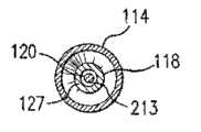
图3是沿线3-3截取的图1的导管110的剖面。在图3中,远端构件127限定导丝腔213,导丝120延伸穿过导丝腔213。球囊114处于膨胀状态,并且远侧锥体115d从远端构件127向外径向延伸。FIG. 3 is a cross-section of
图4是沿线4-4所截取的图1的导管110的剖面。在图4中,远侧裙部116d被密封地固定到远端构件127。远端构件127还限定导丝腔213,导丝120延伸穿过导丝腔213。FIG. 4 is a cross-section of the
需要时,可以将远端构件的近端127P设置在球囊内室中的合适位置。例如,在一个实施例中,近端127P可以位于最接近远侧裙部116d的位置,例如用于支架传递系统等。在另一个实施例中,近端127P从球囊的远端向近侧隔开,如图2A和图2B中所示,例如用于扩张球囊导管。通常,在内管状构件和远端构件的近端之间的接头或结合部位于球囊内部的中心处或中心的远侧。近端127P在球囊114内部的位置允许导管110与常规导管相比更平稳的逐渐过渡。If desired, the
图5A示出了根据所公开主题一个实施例的导管,而图5B示出了已知导管。在图5A中,导管包括在内管状构件118的远侧部分和远端构件127的近侧部分之间的逐渐过渡区。图5A示出了联接到球囊114(导丝120设置在其中)内室中的远端构件127的内管状构件118。不透射线标志140被设置在顶端构件127上。球囊的远侧裙部116d被设置在远端构件127的近端的远侧的远端构件上。此逐渐过渡是通过一个或多个同延长度的内管状构件和远端构件而完成,球囊内室中的结合部的位置、远端构件的锥形形状、远端构件使用比内管状构件更软的材料、和/或远端构件的增加长度而实现。相反,图5B示出了内构件到顶端的突然转变。这种已知的构造增加了当移动经过弯曲路径时在导管远侧部分和导管扭折处的硬度。Figure 5A shows a catheter according to one embodiment of the disclosed subject matter, while Figure 5B shows a known catheter. In FIG. 5A , the catheter includes a gradual transition between the distal portion of the inner
图6A和图6B分别示出了图5A和图5B的导管的远侧视图,参照根据本文中所公开主题的导管。在图6A中,内管状构件118与远端构件127的结合部被设置在球囊114的内室中并且从远侧裙部116d处的远端构件127与球囊114远侧部分的结合部向近侧隔开。此近侧隔开允许导管的逐渐过渡以便增加弹性并且防止扭折。在图6A中,不透射线标志140被设置在远端构件127上。相反,参照如图6B中所示的常规导管,内构件与顶端的结合部位于球囊远端与内构件的结合部处。如图5B和图6B中所示的这种构造形成突然的和较小柔性的过渡。6A and 6B show distal views of the catheter of FIGS. 5A and 5B , respectively, with reference to a catheter according to the subject matter disclosed herein. In FIG. 6A, the junction of the inner
如图1和图7中进一步的示出,并且根据所公开主题的另一方面,导管可以包括至少一个不透射线标志。该不透射线标志可以联接到内管状构件。该标志可以由不透射线的材料制成,例如金属或者不透射线加载的聚合物,例如公开于美国专利序列号11/455,382中,该专利的全部内容以参考的方式并入本文中。As further shown in FIGS. 1 and 7 , and according to another aspect of the disclosed subject matter, the catheter may include at least one radiopaque marker. The radiopaque marker can be coupled to the inner tubular member. The marker can be made of a radiopaque material such as metal or a radiopaque loaded polymer such as disclosed in US Patent Serial No. 11/455,382, which is incorporated herein by reference in its entirety.
标志的位置可以取决于球囊的尺寸。例如,在具有较小球囊的实施例中,可以使用一个不透射线标志,如图1中所示。在使用一个不透射线标志的实施例中,该标志可以位于可膨胀工作长度114w的中央。然而,取决于球囊尺寸,可以在在多种位置设置不透射线标志,包括工作长度段的端部。The location of the markers may depend on the size of the balloon. For example, in embodiments with a smaller balloon, a radiopaque marker may be used, as shown in FIG. 1 . In embodiments using a radiopaque marker, the marker may be located in the center of the expandable working length 114w. However, depending on the balloon size, radiopaque markers may be placed at various locations, including the end of the working length.
图7示出了联接到导管的内管状构件的至少一个标志的另一种布置。导管110具有两个不透射线标志140,标志140位于球囊114的内室141中的内管状构件118上以及沿着球囊114的工作长度114w。在本实施例中,标志140与近侧和远侧锥体部114c大致对准以便将球囊的工作长度114w限定在这两者之间。Figure 7 shows another arrangement of at least one marker coupled to the inner tubular member of the catheter. The
具有标志的导管构造的其它实施例描述于美国专利申请第11/775,480号、美国专利申请第12/945,566号、美国专利第7,862,541号、美国专利申请第12/983,504号、美国专利第7,549,975号、美国专利申请第12/468,745号、美国专利第6,964,750号、美国专利申请第11/455,382号、美国专利第7,833,597号、美国专利第7,322,959号、美国专利第7,303,798号、美国专利申请第11/775,480号、美国专利申请第12/945,566号、美国专利公开2010/0285085、美国专利公开2010/0189876和美国专利申请第11/241,936号,上述文件的全部内容以参考的方式并入本文中。Other examples of catheter configurations with markers are described in U.S. Patent Application No. 11/775,480, U.S. Patent Application No. 12/945,566, U.S. Patent No. 7,862,541, U.S. Patent Application No. 12/983,504, U.S. Patent No. 7,549,975, U.S. Patent Application No. 12/468,745, U.S. Patent No. 6,964,750, U.S. Patent Application No. 11/455,382, U.S. Patent No. 7,833,597, U.S. Patent No. 7,322,959, U.S. Patent No. 7,303,798, U.S. Patent Application No. 11/775,480 , US Patent Application No. 12/945,566, US Patent Publication 2010/0285085, US Patent Publication 2010/0189876, and US Patent Application No. 11/241,936, the entire contents of which are incorporated herein by reference.
导管可以还包括一种联接到球囊的医疗装置。医疗装置的实例包括支架以及类似地利用所述导管和方法而传递的其它合适装置和植入物。为获得关于示例性支架的细节,例如可参见美国专利第5,507,768号(Lau等人)和美国专利第5,458,615号(Klemm等人),这些文件的内容以参考的方式并入本文中。The catheter may also include a medical device coupled to the balloon. Examples of medical devices include stents and other suitable devices and implants similarly delivered using the catheters and methods described. For details on exemplary scaffolds, see, eg, US Patent No. 5,507,768 (Lau et al.) and US Patent No. 5,458,615 (Klemm et al.), the contents of which are incorporated herein by reference.
包括外管状构件和内管状构件的细长管状轴构件可以具有多层构造,其具有一层可容易结合的材料。例如,内管状构件可以具有便于结合到相邻部件的材料(例如聚酰胺)的外层以及光滑/低摩擦材料(例如HDPE)的内层。The elongated tubular shaft member comprising the outer tubular member and the inner tubular member may have a multilayer construction having a layer of readily bondable material. For example, the inner tubular member may have an outer layer of a material that facilitates bonding to adjacent components, such as polyamide, and an inner layer of a slippery/low friction material, such as HDPE.
在另一个实施例中,内管状构件是三层管状构件,其具有通常由光滑材料(例如HDPE)形成的内层、例如官能化的聚烯烃胶粘剂聚合物的中间连接层以及可容易结合的外层(例如聚酰胺,例如尼龙,或者聚醚嵌段酰胺(PEBAX))。In another embodiment, the inner tubular member is a three-layer tubular member having an inner layer generally formed of a lubricious material such as HDPE, an intermediate tie layer such as a functionalized polyolefin adhesive polymer, and an outer layer that can be easily bonded. layer (eg polyamide, eg nylon, or polyether block amide (PEBAX)).
在如图1中所示的实施例中,将球囊114描绘成单层球囊。然而,本文也设想了多层球囊。用于导管的多层球囊的一例描述于美国专利第7,828,766号和美国专利申请第12/897,202号中,这些文件的全部内容以参考的方式并入本文中。此外,具有其它球囊构造的导管的各种实施例描述于美国专利第6,923,822号、美国专利申请第11/189,536、美国专利公开第2009/0036829号和第2007/0021772号,这些文件的全部内容以参考的方式并入本文中。In the embodiment shown in FIG. 1 ,
所公开主题的导管尺寸主要决定于所使用球囊和导丝的尺寸、导管类型和动脉或导管必须经过的其它体腔的尺寸、或者被传递支架的尺寸。例如,外管状构件117可以具有大约0.025至大约0.04英寸(0.064至0.10 cm)的外直径,在一些实施例中为大约0.037英寸(0.094 cm),并且外管状构件117的壁厚可以从大约0.002变化至大约0.008英寸(0.0051至0.02 cm),在一些实施例中大约0.003至0.005英寸(0.0076至0.013 cm)。内管状构件118通常具有大约0.01至大约0.018英寸(0.025至0.046 cm)的内直径,在一些实施例中为大约0.016英寸(0.04 cm),并且具有大约0.004至大约0.008英寸(0.01至0.02 cm)的壁厚。导管110的总长度可以在从大约100至大约150 cm的范围内,并且在一些实施例中约为143 cm。球囊114可以具有大约0.8 cm至大约6 cm(0.315英寸至2.362英寸)的长度以及大约0.5至大约10 mm(0.0197至0.3937英寸)的膨胀后的工作直径。远端构件127的长度可以在从1 mm至35 mm的范围内并且内直径为大约0.010至大约0.035英寸(0.025至0.046 cm),在一些实施例中为大约0.016英寸(0.04 cm),并且壁厚为大约0.004至大约0.008英寸(0.01至0.02 cm)。本文也设想了其它尺寸,并且上述尺寸只是作为例子而提供。The size of the catheter of the disclosed subject matter is primarily determined by the size of the balloon and guide wire used, the type of catheter and the size of the artery or other body lumen through which the catheter must pass, or the size of the stent being delivered. For example, outer
尽管细长管状轴111的管状构件被图示为具有均匀的内直径和外直径以及壁厚,但这些构件可以各自或者同时在沿细长管状轴长度的各种位置具有锥形的内直径和/或外直径。内管状构件118可以具有锥形的远端(即,通过在管状构件的整个圆周形成均匀的锥形而减小管状构件的外直径),并且软的顶端构件的近端可以重叠在锥形的远端上以便结合到该远端。此外并且例如,顶端构件127可以具有比将要被结合到其上的内管状构件的端部更薄的壁厚,在这种情况下,在结合期间,可以对准内表面并且导致内构件的外表面向远侧流动,以使结合部处的外表面平滑。Although the tubular members of the elongated
根据所公开主题的另一方面,公开了一种制作球囊导管的方法。该方法包括提供一种具有近侧部分和远侧部分的细长管状轴,该细长管状轴包括内管状构件,内管状构件具有从细长管状轴的远侧部分向远侧延伸的远侧长度,该细长管状轴具有限定在其中的膨胀腔和导丝腔,导丝腔至少沿内管状构件的远侧长度延伸。该方法还包括提供一种远端构件,其中远端构件是整体的并且包括近端和远端,该远端构件具有限定成穿过其中的导丝腔。远端构件被固定到内管状构件的远端,其中远端构件的导丝腔与内管状构件的导丝腔相连通。提供一种具有近侧部分、远侧部分和在其间的工作长度的球囊,该球囊在其中限定内室。该方法还包括将球囊的近侧部分联接到细长管状轴的远侧部分,使得球囊的内室与膨胀腔流体连通,以及将球囊的远侧部分联接到远端构件,使得远端构件的近端设置在球囊的内部。According to another aspect of the disclosed subject matter, a method of making a balloon catheter is disclosed. The method includes providing an elongated tubular shaft having a proximal portion and a distal portion, the elongated tubular shaft comprising an inner tubular member having a distal end extending distally from the distal portion of the elongated tubular shaft. The elongated tubular shaft has an inflation lumen defined therein and a guidewire lumen extending at least along the distal length of the inner tubular member. The method also includes providing a distal member, wherein the distal member is unitary and includes a proximal end and a distal end, the distal member having a guidewire lumen defined therethrough. A distal member is secured to the distal end of the inner tubular member, wherein the guidewire lumen of the distal member communicates with the guidewire lumen of the inner tubular member. A balloon is provided having a proximal portion, a distal portion, and a working length therebetween, the balloon defining a lumen therein. The method also includes coupling a proximal portion of the balloon to a distal portion of the elongated tubular shaft such that the inner chamber of the balloon is in fluid communication with the inflation lumen, and coupling the distal portion of the balloon to the distal member such that the distal The proximal end of the end member is disposed inside the balloon.
可以利用多种技术可以来联接或以其他方式形成本文中所公开导管的结合部或结合部。例如,参考在球囊和远端构件之间的结合部。为了将球囊的远侧部分联接到远端构件,收缩包覆物可以提供在远端构件和球囊的远侧部分的至少一部分上。利用激光等将球囊的远侧部分的至少该部分热熔接到远端构件。例如,激光可以以螺旋状的方式相对于远端构件的外表面沿其纵向轴线移动。这样,球囊的远侧部分和远端构件的材料将变软和熔融。当激光以螺旋状的方式在顶端构件的纵向轴线周围向远侧移动时移动,将在远侧方向上推进较软的和/或熔融的材料从而在收缩包覆物的下面形成锥形形状。一旦完成,则可除去收缩包覆物。远端构件的远端可以是滚圆的,或者利用激光、研磨或其它方法将形状调整为形成创伤性较小的端部。The junction or joints of the catheters disclosed herein may be joined or otherwise formed using a variety of techniques. For example, refer to the junction between the balloon and the distal member. To couple the distal portion of the balloon to the distal member, a shrink wrap may be provided over the distal member and at least a portion of the distal portion of the balloon. At least the portion of the distal portion of the balloon is thermally fused to the distal member using a laser or the like. For example, the laser may move in a helical fashion relative to the outer surface of the distal member along its longitudinal axis. In this way, the material of the distal portion of the balloon and the distal member will soften and melt. As the laser moves distally about the longitudinal axis of the tip member in a helical fashion, the softer and/or molten material will be pushed in the distal direction to form a conical shape underneath the shrink wrap. Once complete, the shrink wrap can be removed. The distal end of the distal member may be rounded or otherwise shaped using laser, grinding, or other methods to form a less traumatic end.
类似地,当使远端构件的近端结合到内管状构件时,可以在管状构件118、127内部设置芯棒以支撑内腔形状。可以在管状构件118、127上在配对的或联接的表面的位置处设置热缩管(未图示)等,以便于在结合期间形成沿结合部的平滑过渡。在结合形成之后,去除收缩管和芯棒。Similarly, a mandrel may be provided inside the
可利用常规技术来形成细长管状轴外和内管状构件以及顶端构件,例如通过将已发现可用于血管内导管的材料(例如聚乙烯、聚氯乙烯、聚酯类、聚酰胺类、聚酰亚胺类、聚氨酯类和复合材料)进行挤出和颈缩。可利用常规的结合方法(例如但不限于熔接或者使用胶粘剂)将各种构件加以连接。内管状构件和外管状构件可以是多层管,或者端到端连接的管段,如对于球囊导管轴所通常知道的。尽管细长管状轴被图示为具有内和外管状构件,但可以采用多种合适的轴构造,包括具有在其内挤出的并列腔的多腔挤出轴。对于快速交换型构造而言,在快速交换型实施例(未图示)中,外管状构件还可以包括具有高强度构件(例如在近侧轴部和/或经过导丝近侧端口的海波管)的支撑构件。示例性的构造公开于美国专利第7,906,066号中,该专利的全部内容以参考的方式并入本文中。The elongated tubular outer and inner tubular members and the tip member can be formed using conventional techniques, such as by incorporating materials that have been found useful for intravascular catheters (e.g., polyethylene, polyvinyl chloride, polyesters, polyamides, polyamides, etc.) imines, polyurethanes and composites) for extrusion and necking. The various components may be joined using conventional bonding methods such as, but not limited to, welding or the use of adhesives. The inner and outer tubular members may be multilayer tubing, or segments of tubing connected end-to-end, as is commonly known for balloon catheter shafts. Although the elongated tubular shaft is illustrated as having inner and outer tubular members, a variety of suitable shaft configurations may be employed, including multi-lumen extruded shafts having parallel lumens extruded therein. For rapid-exchange configurations, in a rapid-exchange embodiment (not shown), the outer tubular member may also include a hypotenuse with a high-strength member (e.g., at the proximal shaft and/or through the proximal port of the guidewire). tube) support members. Exemplary configurations are disclosed in US Patent No. 7,906,066, which is incorporated herein by reference in its entirety.
在制造期间,可以利用常规技术形成球囊并且利用激光熔合或者热熔合中的至少一种将球囊结合到远端构件。在球囊远侧裙部的热熔合期间,可以将球囊的远侧锥体冷却到远端构件的基本剖面例如通过在远侧锥体处引导冷却流体(例如,空气流)。在结合之前,球囊的远侧裙部116可以具有与远端构件127外直径紧密配合的内直径,使得所形成远侧裙部密封件具有低断面。在组装期间,将远端构件127设置在远侧裙部116d内。因此,在远端构件127位于远侧裙部116d下方的适当位置的情况下,在远侧裙部116d和远端127之间形成结合,如本文中所描述。具有其它球囊构造的导管的各种实施例描述于美国专利第6,923,822号、美国专利申请第11/189,536号、美国专利公开第2009/0036829号和第2007/0021772号,这些文件的全部内容以参考的方式并入本文中。用于导管的多层球囊的一例描述于美国专利第7,828,766号和美国专利申请第12/897,202号中,这些文件的全部内容以参考的方式并入本文中。During manufacture, the balloon may be formed using conventional techniques and bonded to the distal member using at least one of laser fusion or thermal fusion. During thermal fusion of the balloon distal skirt, the distal cone of the balloon may be cooled to a substantial profile of the distal end member, for example by directing a cooling fluid (eg, air flow) at the distal cone. Prior to bonding, the
在所公开主题的另一个实施例中,公开了一种部署球囊导管的方法。该方法包括提供导管,该导管包括具有近侧部分和远侧部分的细长管状轴,该细长管状轴包括内管状构件,内管状构件具有从细长管状轴的远侧部分向远侧延伸的远侧长度。细长管状轴具有膨胀腔和导丝腔限定在其中的,该导丝腔至少沿内管状构件的远侧长度延伸。该导管还包括具有近端和远端的远端构件,其中远端构件是整体的并且远端构件的近端被固定到内管状构件的远端。远端构件具有与内管状构件的导丝腔连通的导丝腔,并且球囊具有近侧部分、远侧部分和在其间的工作长度。球囊的近侧部分密封地联接到细长管状轴的远侧部分,球囊的远侧部分密封地联接到远端构件。球囊限定与膨胀腔流体连通的内室,其中,远端构件的近端被设置在内室质中。该方法还包括将导管的球囊定位在体腔内部以及通过经过细长管状轴的膨胀腔导入加压流体而使球囊膨胀。In another embodiment of the disclosed subject matter, a method of deploying a balloon catheter is disclosed. The method includes providing a catheter comprising an elongated tubular shaft having a proximal portion and a distal portion, the elongated tubular shaft comprising an inner tubular member having a tube extending distally from the distal portion of the elongated tubular shaft. of the distal length. The elongated tubular shaft has an inflation lumen and a guidewire lumen defined therein, the guidewire lumen extending at least along the distal length of the inner tubular member. The catheter also includes a distal member having a proximal end and a distal end, wherein the distal member is unitary and the proximal end of the distal member is secured to the distal end of the inner tubular member. The distal member has a guidewire lumen in communication with the guidewire lumen of the inner tubular member, and the balloon has a proximal portion, a distal portion, and a working length therebetween. A proximal portion of the balloon is sealingly coupled to the distal portion of the elongated tubular shaft, and a distal portion of the balloon is sealingly coupled to the distal member. The balloon defines a lumen in fluid communication with the inflation lumen, wherein the proximal end of the distal member is disposed within the lumen. The method also includes positioning a balloon of the catheter within the body lumen and inflating the balloon by introducing pressurized fluid through the inflation lumen of the elongated tubular shaft.
虽然本文中利用某些实施例描述了公开的主题,但本领域技术人员将认识到在不背离其范围的前提下,可对所公开主题做出各种修改和改进。此外,尽管本文中描述了所公开主题的一个实施例的独立特征,或者在一个实施例但不在其它实施例的图示中示出了独立特征,但应当理解的是一个实施例的独立特征可与另一个实施例的一个或多个特征或者多个实施例的特征相结合。While the disclosed subject matter is described herein using certain embodiments, those skilled in the art will recognize that various modifications and improvements can be made to the disclosed subject matter without departing from its scope. Furthermore, although individual features of one embodiment of the disclosed subject matter are described herein or shown in illustrations of one embodiment but not others, it is to be understood that individual features of one embodiment may be In combination with one or more features of another embodiment or features of multiple embodiments.
应当理解的是,可以对本公开的主题的以上描述作出各种修改、变化和调整,并且这些修改、变化和调整意图被包括在所附权利要求及其等同物的含义和范围内。It should be understood that various modifications, changes and adjustments may be made to the above description of the disclosed subject matter and are intended to be included within the meaning and scope of the appended claims and their equivalents.
Claims (26)
Priority Applications (1)
| Application Number | Priority Date | Filing Date | Title |
|---|---|---|---|
| CN201710092876.7ACN107007921B (en) | 2011-05-26 | 2012-05-25 | Through tip of catheter |
Applications Claiming Priority (3)
| Application Number | Priority Date | Filing Date | Title |
|---|---|---|---|
| US201161490444P | 2011-05-26 | 2011-05-26 | |
| US61/490444 | 2011-05-26 | ||
| PCT/US2012/039700WO2012162661A1 (en) | 2011-05-26 | 2012-05-25 | Through tip for a catheter |
Related Child Applications (1)
| Application Number | Title | Priority Date | Filing Date |
|---|---|---|---|
| CN201710092876.7ADivisionCN107007921B (en) | 2011-05-26 | 2012-05-25 | Through tip of catheter |
Publications (2)
| Publication Number | Publication Date |
|---|---|
| CN103764217Atrue CN103764217A (en) | 2014-04-30 |
| CN103764217B CN103764217B (en) | 2017-03-15 |
Family
ID=46201882
Family Applications (2)
| Application Number | Title | Priority Date | Filing Date |
|---|---|---|---|
| CN201710092876.7AExpired - Fee RelatedCN107007921B (en) | 2011-05-26 | 2012-05-25 | Through tip of catheter |
| CN201280025222.8AExpired - Fee RelatedCN103764217B (en) | 2011-05-26 | 2012-05-25 | through tip of catheter |
Family Applications Before (1)
| Application Number | Title | Priority Date | Filing Date |
|---|---|---|---|
| CN201710092876.7AExpired - Fee RelatedCN107007921B (en) | 2011-05-26 | 2012-05-25 | Through tip of catheter |
Country Status (4)
| Country | Link |
|---|---|
| US (4) | US10406329B2 (en) |
| EP (1) | EP2714179A1 (en) |
| CN (2) | CN107007921B (en) |
| WO (1) | WO2012162661A1 (en) |
Cited By (7)
| Publication number | Priority date | Publication date | Assignee | Title |
|---|---|---|---|---|
| CN103223207A (en)* | 2012-01-31 | 2013-07-31 | 株式会社戈德曼 | A balloon catheter |
| CN105536121A (en)* | 2014-09-04 | 2016-05-04 | 雅培心血管系统有限公司 | Balloon catheter |
| CN106166322A (en)* | 2015-05-19 | 2016-11-30 | 雅培心血管系统有限公司 | There is the conduit of monoblock type multilamellar distally external member |
| CN107243107A (en)* | 2017-06-12 | 2017-10-13 | 南方医科大学 | Peritoneal cavity drainage tube |
| CN110167466A (en)* | 2016-11-04 | 2019-08-23 | 莱斯桑柏特医疗解决方案股份有限公司 | The device for passing through foley's tube for conveying machinery wave |
| CN113069669A (en)* | 2016-02-16 | 2021-07-06 | 埃姆博尔克斯公司 | Balloon catheter and methods of making and using |
| US12409298B2 (en) | 2019-08-20 | 2025-09-09 | Embolx, Inc. | Catheters and methods of manufacture and use |
Families Citing this family (19)
| Publication number | Priority date | Publication date | Assignee | Title |
|---|---|---|---|---|
| EP2560722A2 (en) | 2010-04-21 | 2013-02-27 | The Regents of the University of Michigan | Fluoroscopy-independent, endovascular aortic occlusion system |
| CN107096111A (en) | 2011-05-26 | 2017-08-29 | 雅培心血管系统有限公司 | The conduit of thin hypotube is cut with stairstepping |
| CN107007921B (en)* | 2011-05-26 | 2020-01-21 | 雅培心血管系统有限公司 | Through tip of catheter |
| US8840743B2 (en) | 2012-09-11 | 2014-09-23 | Abbott Cardiovascular Systems Inc. | Soft tip balloon catheter |
| US9078740B2 (en) | 2013-01-21 | 2015-07-14 | Howmedica Osteonics Corp. | Instrumentation and method for positioning and securing a graft |
| US10569062B2 (en) | 2013-09-09 | 2020-02-25 | Prytime Medical Devices, Inc. | Low profile occlusion catheter |
| US10232142B2 (en) | 2014-06-10 | 2019-03-19 | Prytime Medical Devices, Inc. | Conduit guiding tip |
| CN205287203U (en) | 2014-09-04 | 2016-06-08 | 雅培心血管系统有限公司 | balloon catheter |
| CA2980018C (en) | 2015-03-19 | 2018-02-20 | Prytime Medical Devices, Inc. | System and method for low-profile occlusion balloon catheter |
| CN106166323A (en) | 2015-05-19 | 2016-11-30 | 雅培心血管系统有限公司 | Balloon catheter |
| US10368872B2 (en) | 2016-06-02 | 2019-08-06 | Prytime Medical Devices, Inc. | System and method for low profile occlusion balloon catheter |
| EP4327732A3 (en) | 2017-01-12 | 2024-04-24 | The Regents of The University of California | Endovascular perfusion augmentation for critical care |
| CA3060519A1 (en) | 2017-04-21 | 2018-10-25 | The Regents Of The University Of California | Aortic flow meter and pump for partial-aortic occlusion |
| US20190307993A1 (en)* | 2018-04-04 | 2019-10-10 | Qxmedical, Llc | Low Profile Balloon Catheter And Related Systems And Methods |
| EP3833273A4 (en) | 2018-08-06 | 2022-06-29 | Prytime Medical Devices, Inc. | System and method for low profile occlusion balloon catheter |
| US12420069B2 (en) | 2018-12-19 | 2025-09-23 | Covidien Lp | Internal carotid artery thrombectomy devices and methods |
| EP4121159A2 (en) | 2020-03-16 | 2023-01-25 | Certus Critical Care, Inc. | Blood flow control devices, systems, and methods and error detection thereof |
| WO2022024348A1 (en)* | 2020-07-31 | 2022-02-03 | 朝日インテック株式会社 | Balloon catheter |
| WO2022197895A1 (en) | 2021-03-18 | 2022-09-22 | Prytime Medical Devices, Inc. | Vascular occlusion catheter |
Citations (4)
| Publication number | Priority date | Publication date | Assignee | Title |
|---|---|---|---|---|
| US5304134A (en)* | 1992-01-17 | 1994-04-19 | Danforth Biomedical, Inc. | Lubricious yet bondable catheter channel sleeve for over-the-wire catheters |
| US5769819A (en)* | 1997-04-24 | 1998-06-23 | Medtronic, Inc. | Catheter distal tip component |
| WO2007146572A2 (en)* | 2006-06-15 | 2007-12-21 | Medtronic Vascular, Inc. | Catheter assembly having a grooved distal tip |
| US20090156998A1 (en)* | 2007-12-17 | 2009-06-18 | Abbott Cardiovascular Systems Inc. | Catheter having transitioning shaft segments |
Family Cites Families (256)
| Publication number | Priority date | Publication date | Assignee | Title |
|---|---|---|---|---|
| US4425919A (en) | 1981-07-27 | 1984-01-17 | Raychem Corporation | Torque transmitting catheter apparatus |
| US4563181A (en) | 1983-02-18 | 1986-01-07 | Mallinckrodt, Inc. | Fused flexible tip catheter |
| US4596563A (en) | 1983-06-09 | 1986-06-24 | Cordis Corporation | Thin-walled multi-layered catheter having a fuseless tip |
| US4921483A (en) | 1985-12-19 | 1990-05-01 | Leocor, Inc. | Angioplasty catheter |
| US5350395A (en) | 1986-04-15 | 1994-09-27 | Yock Paul G | Angioplasty apparatus facilitating rapid exchanges |
| US5061273A (en) | 1989-06-01 | 1991-10-29 | Yock Paul G | Angioplasty apparatus facilitating rapid exchanges |
| US4721117A (en)* | 1986-04-25 | 1988-01-26 | Advanced Cardiovascular Systems, Inc. | Torsionally stabilized guide wire with outer jacket |
| US4775371A (en) | 1986-09-02 | 1988-10-04 | Advanced Cardiovascular Systems, Inc. | Stiffened dilatation catheter and method of manufacture |
| US5312430A (en) | 1986-12-09 | 1994-05-17 | Rosenbluth Robert F | Balloon dilation catheter |
| US4886506A (en) | 1986-12-23 | 1989-12-12 | Baxter Travenol Laboratories, Inc. | Soft tip catheter |
| US4782834A (en) | 1987-01-06 | 1988-11-08 | Advanced Cardiovascular Systems, Inc. | Dual lumen dilatation catheter and method of manufacturing the same |
| US4976720A (en) | 1987-01-06 | 1990-12-11 | Advanced Cardiovascular Systems, Inc. | Vascular catheters |
| US5358486A (en) | 1987-01-09 | 1994-10-25 | C. R. Bard, Inc. | Multiple layer high strength balloon for dilatation catheter |
| US4820349A (en) | 1987-08-21 | 1989-04-11 | C. R. Bard, Inc. | Dilatation catheter with collapsible outer diameter |
| US4892519A (en) | 1987-12-03 | 1990-01-09 | Advanced Cardiovascular Systems, Inc. | Steerable perfusion dilatation catheter |
| US5156594A (en) | 1990-08-28 | 1992-10-20 | Scimed Life Systems, Inc. | Balloon catheter with distal guide wire lumen |
| US5078702A (en) | 1988-03-25 | 1992-01-07 | Baxter International Inc. | Soft tip catheters |
| US4877031A (en) | 1988-07-22 | 1989-10-31 | Advanced Cardiovascular Systems, Inc. | Steerable perfusion dilatation catheter |
| US5207700A (en) | 1988-08-08 | 1993-05-04 | Scimed Life Systems, Inc. | Polyimide balloon catheter and method of forming a balloon therefor |
| US4952357A (en) | 1988-08-08 | 1990-08-28 | Scimed Life Systems, Inc. | Method of making a polyimide balloon catheter |
| US5499980A (en) | 1988-08-08 | 1996-03-19 | Scimed Life Systems, Inc. | Polyimide balloon catheter and method of making same |
| US5176661A (en) | 1988-09-06 | 1993-01-05 | Advanced Cardiovascular Systems, Inc. | Composite vascular catheter |
| US5304197A (en) | 1988-10-04 | 1994-04-19 | Cordis Corporation | Balloons for medical devices and fabrication thereof |
| US5335675A (en) | 1988-11-15 | 1994-08-09 | Family Health International | Stress-softened elastomeric films, articles, and method and apparatus for making such films and articles |
| US5032113A (en) | 1989-04-13 | 1991-07-16 | Scimed Life Systems, Inc. | Innerless catheter |
| US5454789A (en) | 1989-01-13 | 1995-10-03 | Scimed Life Systems, Inc. | Innerless dilatation balloon catheter |
| US5112304A (en) | 1989-03-17 | 1992-05-12 | Angeion Corporation | Balloon catheter |
| US5100381A (en) | 1989-11-13 | 1992-03-31 | Scimed Life Systems, Inc. | Angioplasty catheter |
| US5047045A (en) | 1989-04-13 | 1991-09-10 | Scimed Life Systems, Inc. | Multi-section coaxial angioplasty catheter |
| US5759191A (en)* | 1989-06-27 | 1998-06-02 | C. R. Bard, Inc. | Coaxial PTCA catheter with anchor joint |
| US6179856B1 (en) | 1989-07-05 | 2001-01-30 | Medtronic Ave, Inc. | Coaxial PTCA catheter with anchor joint |
| US4976690A (en) | 1989-08-10 | 1990-12-11 | Scimed Life Systems, Inc. | Variable stiffness angioplasty catheter |
| US5484409A (en) | 1989-08-25 | 1996-01-16 | Scimed Life Systems, Inc. | Intravascular catheter and method for use thereof |
| EP0414350B1 (en) | 1989-08-25 | 1994-08-24 | C.R. Bard, Inc. | Pleated balloon dilatation catheter and method of manufacture |
| DE69002295T2 (en) | 1989-09-25 | 1993-11-04 | Schneider Usa Inc | MULTILAYER EXTRUSION AS A METHOD FOR PRODUCING BALLOONS FOR VESSEL PLASTICS. |
| US5364357A (en) | 1989-09-25 | 1994-11-15 | Schneider (Usa) Inc. | Small diameter dilatation catheter having wire reinforced coaxial tubular body |
| US5256144A (en)* | 1989-11-02 | 1993-10-26 | Danforth Biomedical, Inc. | Low profile, high performance interventional catheters |
| US5478320A (en) | 1989-11-29 | 1995-12-26 | Cordis Corporation | Puncture resistant balloon catheter and method of manufacturing |
| US5290306A (en) | 1989-11-29 | 1994-03-01 | Cordis Corporation | Puncture resistant balloon catheter |
| US5342301A (en) | 1992-08-13 | 1994-08-30 | Advanced Polymers Incorporated | Multi-lumen balloons and catheters made therewith |
| US6004289A (en) | 1990-05-15 | 1999-12-21 | Medtronic Ave, Inc. | Multiple layer high strength balloon for dilatation catheter |
| US5217482A (en) | 1990-08-28 | 1993-06-08 | Scimed Life Systems, Inc. | Balloon catheter with distal guide wire lumen |
| EP0476807A1 (en) | 1990-09-17 | 1992-03-25 | C.R. Bard, Inc. | Core wire steerable catheters |
| US5423754A (en) | 1990-09-20 | 1995-06-13 | Scimed Life Systems, Inc. | Intravascular catheter |
| US5085649A (en) | 1990-11-21 | 1992-02-04 | Flynn Vincent J | Torque controlled tubing |
| CA2060067A1 (en) | 1991-01-28 | 1992-07-29 | Lilip Lau | Stent delivery system |
| US5195969A (en) | 1991-04-26 | 1993-03-23 | Boston Scientific Corporation | Co-extruded medical balloons and catheter using such balloons |
| CA2068483A1 (en) | 1991-05-15 | 1992-11-16 | Motasim Mahmoud Sirhan | Low profile dilatation catheter |
| US5743875A (en) | 1991-05-15 | 1998-04-28 | Advanced Cardiovascular Systems, Inc. | Catheter shaft with an oblong transverse cross-section |
| US5205822A (en) | 1991-06-10 | 1993-04-27 | Cordis Corporation | Replaceable dilatation catheter |
| EP0592720B1 (en) | 1991-06-10 | 1998-07-29 | Cordis Corporation | Replaceable dilatation catheter |
| US5490837A (en) | 1991-07-05 | 1996-02-13 | Scimed Life Systems, Inc. | Single operator exchange catheter having a distal catheter shaft section |
| US5795325A (en) | 1991-07-16 | 1998-08-18 | Heartport, Inc. | Methods and apparatus for anchoring an occluding member |
| US5766151A (en) | 1991-07-16 | 1998-06-16 | Heartport, Inc. | Endovascular system for arresting the heart |
| US5879499A (en) | 1996-06-17 | 1999-03-09 | Heartport, Inc. | Method of manufacture of a multi-lumen catheter |
| US5378238A (en) | 1991-10-15 | 1995-01-03 | Scimed Life Systems, Inc. | Innerless dilatation catheter with balloon stretch or manual valve |
| US5338295A (en) | 1991-10-15 | 1994-08-16 | Scimed Life Systems, Inc. | Dilatation catheter with polyimide-encased stainless steel braid proximal shaft |
| US5217434A (en) | 1991-10-15 | 1993-06-08 | Scimed Life Systems, Inc. | Innerless dilatation catheter with balloon stretch valve |
| US5250059A (en) | 1992-01-22 | 1993-10-05 | Devices For Vascular Intervention, Inc. | Atherectomy catheter having flexible nose cone |
| US5318032A (en) | 1992-02-05 | 1994-06-07 | Devices For Vascular Intervention | Guiding catheter having soft tip |
| US5649909A (en) | 1992-04-06 | 1997-07-22 | Scimed Life Systems, Inc. | Variable stiffness multi-lumen catheter |
| US5318525A (en) | 1992-04-10 | 1994-06-07 | Medtronic Cardiorhythm | Steerable electrode catheter |
| WO1993020882A1 (en) | 1992-04-20 | 1993-10-28 | Advanced Cardiovascular Systems, Inc. | Low profile dilatation catheter |
| US5447497A (en) | 1992-08-06 | 1995-09-05 | Scimed Life Systems, Inc | Balloon catheter having nonlinear compliance curve and method of using |
| US5318526A (en) | 1992-09-29 | 1994-06-07 | Neuro Navigational Corporation | Flexible endoscope with hypotube activating wire support |
| US5300025A (en) | 1992-09-30 | 1994-04-05 | Advanced Cardiovascular Systems, Inc. | Dilatation catheter having a coil supported inflation lumen |
| JP3310031B2 (en) | 1992-10-23 | 2002-07-29 | テルモ株式会社 | Catheter tube |
| US5342386A (en) | 1992-10-26 | 1994-08-30 | Cordis Corporation | Catheter with multiple flexibilities along the shaft |
| US5512051A (en) | 1993-02-16 | 1996-04-30 | Boston Scientific Corporation | Slip-layered catheter balloon |
| ES2118392T3 (en) | 1993-04-09 | 1998-09-16 | Schneider Usa Inc | DILATOR CATHETER WITH FLEXIBLE CUSHION POINT. |
| US5395336A (en) | 1993-04-26 | 1995-03-07 | Mallinckrodt Medical, Inc. | Method for joining portions of a inflation/expansion catheter and a catheter so formed |
| US5437632A (en) | 1993-06-02 | 1995-08-01 | Target Therapeutics, Inc. | Variable stiffness balloon catheter |
| US5458615A (en) | 1993-07-06 | 1995-10-17 | Advanced Cardiovascular Systems, Inc. | Stent delivery system |
| US6896842B1 (en) | 1993-10-01 | 2005-05-24 | Boston Scientific Corporation | Medical device balloons containing thermoplastic elastomers |
| JP3577082B2 (en) | 1993-10-01 | 2004-10-13 | ボストン・サイエンティフィック・コーポレーション | Medical device balloon made of thermoplastic elastomer |
| WO1995018647A2 (en) | 1994-01-06 | 1995-07-13 | Scimed Life Systems Inc | Thermoplastic polyimide balloon catheter |
| US5538510A (en) | 1994-01-31 | 1996-07-23 | Cordis Corporation | Catheter having coextruded tubing |
| US5911715A (en) | 1994-02-14 | 1999-06-15 | Scimed Life Systems, Inc. | Guide catheter having selected flexural modulus segments |
| US6146356A (en) | 1994-03-02 | 2000-11-14 | Scimed Life Systems, Inc. | Block copolymer elastomer catheter balloons |
| ES2141928T5 (en) | 1994-03-02 | 2009-04-16 | Boston Scientific Limited | BALLS OF ELASTOMERO COPOLIMERO IN BLOCKS FOR CATHETER. |
| US6171278B1 (en) | 1994-03-02 | 2001-01-09 | Scimed Life Systems, Inc. | Block copolymer elastomer catheter balloons |
| US5902290A (en) | 1994-03-14 | 1999-05-11 | Advanced Cardiovascular Systems, Inc. | Catheter providing intraluminal access |
| FR2718645B1 (en) | 1994-04-15 | 1996-07-12 | Nycomed Lab Sa | Rapid exchange dilation catheter. |
| US5533985A (en) | 1994-04-20 | 1996-07-09 | Wang; James C. | Tubing |
| US5554121B1 (en) | 1994-07-25 | 1998-07-14 | Advanced Cardiovascular System | Intraluminal catheter with high strength proximal shaft |
| US5554120A (en) | 1994-07-25 | 1996-09-10 | Advanced Cardiovascular Systems, Inc. | Polymer blends for use in making medical devices including catheters and balloons for dilatation catheters |
| US5669383A (en) | 1994-07-28 | 1997-09-23 | Sims Deltec, Inc. | Polyimide sheath for a catheter detector and method |
| US5587125A (en) | 1994-08-15 | 1996-12-24 | Schneider (Usa) Inc. | Non-coextrusion method of making multi-layer angioplasty balloons |
| US5743874A (en) | 1994-08-29 | 1998-04-28 | Fischell; Robert E. | Integrated catheter for balloon angioplasty and stent delivery |
| US5470315A (en) | 1994-09-20 | 1995-11-28 | Scimed Life Systems, Inc. | Over-the-wire type balloon catheter with proximal hypotube |
| US5632760A (en) | 1994-10-20 | 1997-05-27 | Cordis Corporation | Balloon catheter for stent implantation |
| US5658264A (en) | 1994-11-10 | 1997-08-19 | Target Therapeutics, Inc. | High performance spiral-wound catheter |
| EP0794811B1 (en) | 1994-11-23 | 2002-07-31 | Micro Interventional Systems, Inc. | High torque balloon catheter |
| US5599326A (en) | 1994-12-20 | 1997-02-04 | Target Therapeutics, Inc. | Catheter with multi-layer section |
| AU4605896A (en) | 1995-01-04 | 1996-07-24 | Medtronic, Inc. | Improved method of soft tip forming |
| US6017577A (en) | 1995-02-01 | 2000-01-25 | Schneider (Usa) Inc. | Slippery, tenaciously adhering hydrophilic polyurethane hydrogel coatings, coated polymer substrate materials, and coated medical devices |
| US5549552A (en) | 1995-03-02 | 1996-08-27 | Scimed Life Systems, Inc. | Balloon dilation catheter with improved pushability, trackability and crossability |
| AU5189496A (en) | 1995-03-30 | 1996-10-16 | Heartport, Inc. | Endovascular cardiac venting catheter and method |
| AU5558096A (en) | 1995-05-01 | 1996-11-21 | Medtronic Cardiorhythm | Dual curve ablation catheter and method |
| US5833657A (en) | 1995-05-30 | 1998-11-10 | Ethicon, Inc. | Single-walled balloon catheter with non-linear compliance characteristic |
| WO1996038194A2 (en) | 1995-06-01 | 1996-12-05 | Scimed Life Systems, Inc. | Flow assisted catheter |
| WO1996040342A1 (en) | 1995-06-07 | 1996-12-19 | Cardima, Inc. | Guiding catheter for coronary sinus |
| DE69636829T3 (en) | 1995-10-11 | 2016-07-21 | Terumo K.K. | Balloon for catheters and balloon catheters |
| US5843050A (en) | 1995-11-13 | 1998-12-01 | Micro Therapeutics, Inc. | Microcatheter |
| US5772641A (en) | 1995-12-12 | 1998-06-30 | Medi-Dyne Inc. | Overlapping welds for catheter constructions |
| US5643209A (en) | 1995-12-15 | 1997-07-01 | Medtronic, Inc. | High pressure balloon tip |
| JP2000507117A (en) | 1996-01-31 | 2000-06-13 | イー・アイ・デユポン・ドウ・ヌムール・アンド・カンパニー | Dilatation catheter balloon with improved puncture resistance |
| US6124007A (en) | 1996-03-06 | 2000-09-26 | Scimed Life Systems Inc | Laminate catheter balloons with additive burst strength and methods for preparation of same |
| US6071266A (en) | 1996-04-26 | 2000-06-06 | Kelley; Donald W. | Lubricious medical devices |
| US6488637B1 (en) | 1996-04-30 | 2002-12-03 | Target Therapeutics, Inc. | Composite endovascular guidewire |
| US5782811A (en) | 1996-05-30 | 1998-07-21 | Target Therapeutics, Inc. | Kink-resistant braided catheter with distal side holes |
| SE9602529D0 (en) | 1996-06-26 | 1996-06-26 | Astra Ab | Medical device |
| US5797887A (en) | 1996-08-27 | 1998-08-25 | Novovasc Llc | Medical device with a surface adapted for exposure to a blood stream which is coated with a polymer containing a nitrosyl-containing organo-metallic compound which releases nitric oxide from the coating to mediate platelet aggregation |
| US6004339A (en) | 1996-11-13 | 1999-12-21 | Angiodynamics Incorporated | Balloon catheter with multiple distensibilities |
| US5690613A (en) | 1996-12-06 | 1997-11-25 | Medtronic, Inc. | Rapid exchange high pressure transition for high pressure catheter with non-compliant balloon |
| US5779731A (en) | 1996-12-20 | 1998-07-14 | Cordis Corporation | Balloon catheter having dual markers and method |
| US5791036A (en) | 1996-12-23 | 1998-08-11 | Schneider (Usa) Inc | Catheter transition system |
| US5769817A (en) | 1997-02-28 | 1998-06-23 | Schneider (Usa) Inc. | Coextruded balloon and method of making same |
| US5792144A (en) | 1997-03-31 | 1998-08-11 | Cathco, Inc. | Stent delivery catheter system |
| JPH10290837A (en) | 1997-04-18 | 1998-11-04 | Kanegafuchi Chem Ind Co Ltd | Balloon catheter and manufacture of multi-lumen shaft used therefor |
| US6165166A (en) | 1997-04-25 | 2000-12-26 | Schneider (Usa) Inc. | Trilayer, extruded medical tubing and medical devices incorporating such tubing |
| CA2232250C (en) | 1997-05-14 | 2007-06-26 | Navius Corporation | Balloon for a dilation catheter and method for manufacturing a balloon |
| US6165195A (en) | 1997-08-13 | 2000-12-26 | Advanced Cardiovascylar Systems, Inc. | Stent and catheter assembly and method for treating bifurcations |
| EP0904795A1 (en) | 1997-09-05 | 1999-03-31 | Cordis Webster, Inc. | Thin-walled catheter with high torsional stiffness |
| US6242063B1 (en) | 1997-09-10 | 2001-06-05 | Scimed Life Systems, Inc. | Balloons made from liquid crystal polymer blends |
| US6358227B1 (en) | 1997-09-10 | 2002-03-19 | Scimed Life Systems, Inc. | Dilatation catheter balloon made from pen based homopolymer or random copolymer |
| WO1999013924A2 (en) | 1997-09-17 | 1999-03-25 | Advanced Cardiovascular Systems, Inc. | Polyether block amide catheter balloons |
| US6010521A (en) | 1997-11-25 | 2000-01-04 | Advanced Cardiovasular Systems, Inc. | Catheter member with bondable layer |
| US6027510A (en) | 1997-12-08 | 2000-02-22 | Inflow Dynamics Inc. | Stent delivery system |
| US6036670A (en) | 1997-12-23 | 2000-03-14 | Cordis Corporation | Coiled transition balloon catheter, assembly and procedure |
| US6129707A (en) | 1998-01-21 | 2000-10-10 | Advanced Cardiovascular Systems, Inc. | Intravascular catheter with expanded distal tip |
| JP3691236B2 (en) | 1998-01-23 | 2005-09-07 | 朝日インテック株式会社 | catheter |
| US6056719A (en) | 1998-03-04 | 2000-05-02 | Scimed Life Systems, Inc. | Convertible catheter incorporating a collapsible lumen |
| US6179827B1 (en) | 1998-03-16 | 2001-01-30 | Chase Medical | Catheter having integral expandable/collapsible lumen |
| US5964778A (en) | 1998-03-17 | 1999-10-12 | Medtronic, Inc. | Balloon attachment at catheter tip |
| US20010001113A1 (en) | 1998-04-21 | 2001-05-10 | Florencia Lim | Balloon catheter |
| US6673291B1 (en) | 1998-05-01 | 2004-01-06 | Smiths Group Plc | Methods of manufacturing medico-surgical tubes |
| US6342047B1 (en) | 1998-06-02 | 2002-01-29 | Terumo Kabushiki Kaisha | Indwelling catheter |
| CN2332195Y (en) | 1998-06-11 | 1999-08-11 | 齐晓明 | Novel man underpants and its lining |
| US6416494B1 (en) | 1998-06-11 | 2002-07-09 | Infinity Extrusion & Engineering, Inc. | Semi-compliant catheter balloons and methods of manufacture thereof |
| EP1096965B1 (en) | 1998-07-16 | 2007-12-05 | Mark Cohen | Reinforced variable stiffness tubing |
| US6024693A (en) | 1998-10-16 | 2000-02-15 | Datascope Investment Corp. | Intra-aortic balloon catheter |
| US6264063B1 (en) | 1998-10-23 | 2001-07-24 | Vought Aircraft Industries, Inc. | Orientation maintained fastener delivery system and method |
| US6102890A (en) | 1998-10-23 | 2000-08-15 | Scimed Life Systems, Inc. | Catheter having improved proximal shaft design |
| US6245053B1 (en) | 1998-11-09 | 2001-06-12 | Medtronic, Inc. | Soft tip guiding catheter and method of fabrication |
| US6171275B1 (en) | 1998-12-03 | 2001-01-09 | Cordis Webster, Inc. | Irrigated split tip electrode catheter |
| US6197015B1 (en) | 1998-12-09 | 2001-03-06 | Medi-Dyne Inc. | Angiography catheter with sections having different mechanical properties |
| CA2369307C (en)* | 1999-05-11 | 2009-04-07 | Kaneka Corporation | Balloon catheter |
| US6306097B1 (en) | 1999-06-17 | 2001-10-23 | Acuson Corporation | Ultrasound imaging catheter guiding assembly with catheter working port |
| US6210396B1 (en) | 1999-06-24 | 2001-04-03 | Medtronic, Inc. | Guiding catheter with tungsten loaded band |
| US6193686B1 (en) | 1999-06-30 | 2001-02-27 | Advanced Cardiovascular Systems, Inc. | Catheter with enhanced flexibility |
| US6179810B1 (en) | 1999-08-17 | 2001-01-30 | Advanced Cardiovascular Systems, Inc. | Catheter with a flexible and pushable shaft |
| DE60042414D1 (en) | 1999-08-27 | 2009-07-30 | Angiodevice Internat Gmbh | INTERPENETRATING POLYMER NETWORKS FOR USE |
| US6695809B1 (en) | 1999-09-13 | 2004-02-24 | Advanced Cardiovascular Systems, Inc. | Catheter balloon with a discontinuous elastomeric outer layer |
| US6702802B1 (en) | 1999-11-10 | 2004-03-09 | Endovascular Technologies, Inc. | Catheters with improved transition |
| JP2001353225A (en) | 2000-06-15 | 2001-12-25 | Terumo Corp | Catheter |
| GB9927814D0 (en) | 1999-11-26 | 2000-01-26 | Smiths Industries Plc | Tubes |
| US6549812B1 (en) | 1999-11-29 | 2003-04-15 | Medtronic, Inc. | Medical electrical lead having bending stiffness which increase in the distal direction |
| US6620127B2 (en) | 1999-12-01 | 2003-09-16 | Advanced Cardiovascular Systems, Inc. | Medical device balloon |
| US6579484B1 (en) | 1999-12-16 | 2003-06-17 | Advanced Cardiovascular Systems, Inc. | Co-extruded taper shaft |
| US6589207B1 (en) | 1999-12-21 | 2003-07-08 | Advanced Cardiovascular Systems, Inc. | Rapid exchange catheter having a support mandrel |
| US6602224B1 (en) | 1999-12-22 | 2003-08-05 | Advanced Cardiovascular Systems, Inc. | Medical device formed of ultrahigh molecular weight polyolefin |
| US6641694B1 (en) | 1999-12-22 | 2003-11-04 | Advanced Cardiovascular Systems, Inc. | Angioplasty balloon with thin-walled taper and method of making the same |
| US6572813B1 (en) | 2000-01-13 | 2003-06-03 | Advanced Cardiovascular Systems, Inc. | Balloon forming process |
| US6756094B1 (en) | 2000-02-28 | 2004-06-29 | Scimed Life Systems, Inc. | Balloon structure with PTFE component |
| US7947059B2 (en) | 2000-03-02 | 2011-05-24 | Boston Scientific Scimed, Inc. | Multilayer medical device |
| US6585687B1 (en) | 2000-03-27 | 2003-07-01 | Cordis Corporation | Inflatable balloon catheter body construction |
| US6508784B1 (en) | 2000-05-19 | 2003-01-21 | Yan-Ho Shu | Balloon catheter having adjustable centering capabilities and methods thereof |
| US7862541B2 (en) | 2000-05-22 | 2011-01-04 | Abbott Laboratories Vascular Enterprises Limited | Catheter having a soft distal tip |
| US6575958B1 (en) | 2000-05-23 | 2003-06-10 | Advanced Cardiovascular Systems, Inc. | Catheter with improved transition |
| US6364894B1 (en) | 2000-06-12 | 2002-04-02 | Cordis Corporation | Method of making an angioplasty balloon catheter |
| EP1289597B1 (en) | 2000-06-16 | 2006-03-08 | Abbott Laboratories | Balloon occlusion device having a proximal valve |
| GB2370506B (en) | 2000-10-04 | 2005-02-16 | Biocompatibles Ltd | Catheter tip |
| US6589226B1 (en) | 2000-10-20 | 2003-07-08 | Advanced Cardiovascular Systems, Inc. | Catheter shaft and method of making a catheter shaft |
| US6620128B1 (en) | 2000-10-20 | 2003-09-16 | Advanced Cardiovascular Systems, Inc. | Balloon blowing process with metered volumetric inflation |
| US7229518B1 (en) | 2000-11-02 | 2007-06-12 | Nike, Inc. | Process for improving interfacial adhesion in a laminate |
| US6663614B1 (en) | 2000-11-06 | 2003-12-16 | Advanced Cardiovascular Systems, Inc. | Catheter shaft having variable thickness layers and method of making |
| US6875197B1 (en) | 2000-11-14 | 2005-04-05 | Advanced Cardiovascular Systems, Inc. | Dimensionally stable and growth controlled inflatable member for a catheter |
| US6575934B2 (en)* | 2000-12-21 | 2003-06-10 | Advanced Cardiovascular Systems, Inc. | Low profile catheter |
| US6893456B2 (en) | 2000-12-22 | 2005-05-17 | Advanced Cardiovascular Systems, Inc. | Catheter and method for making the same |
| US8277868B2 (en) | 2001-01-05 | 2012-10-02 | Abbott Cardiovascular Systems Inc. | Balloon catheter for delivering therapeutic agents |
| US6673302B2 (en) | 2001-01-24 | 2004-01-06 | Scimed Life Systems, Inc. | Wet processing method for catheter balloons |
| US6740191B2 (en) | 2001-02-22 | 2004-05-25 | Medtronic Ave, Inc. | Through-transmission welding of catheter components |
| RU2003129519A (en) | 2001-03-05 | 2005-01-20 | Унилевер Нв (Nl) | BLACK TEA PRODUCTION |
| US6796960B2 (en) | 2001-05-04 | 2004-09-28 | Wit Ip Corporation | Low thermal resistance elastic sleeves for medical device balloons |
| US6911038B2 (en) | 2001-05-08 | 2005-06-28 | Scimed Life Systems, Inc. | Matched balloon to stent shortening |
| US20030009151A1 (en) | 2001-07-03 | 2003-01-09 | Scimed Life Systems, Inc. | Biaxially oriented multilayer polymer tube for medical devices |
| US20030005544A1 (en)* | 2001-07-06 | 2003-01-09 | Felix Harold St. | Integrated toothbrush and floss dispenser |
| US6626889B1 (en) | 2001-07-25 | 2003-09-30 | Advanced Cardiovascular Systems, Inc. | Thin-walled guiding catheter with improved radiopacity |
| US6692461B2 (en) | 2001-08-07 | 2004-02-17 | Advanced Cardiovascular Systems, Inc. | Catheter tip |
| US6946092B1 (en) | 2001-09-10 | 2005-09-20 | Scimed Life Systems, Inc. | Medical balloon |
| US6863678B2 (en) | 2001-09-19 | 2005-03-08 | Advanced Cardiovascular Systems, Inc. | Catheter with a multilayered shaft section having a polyimide layer |
| US6979342B2 (en)* | 2001-09-19 | 2005-12-27 | Advanced Cardiovascular Systems, Incc | Catheter with a polyimide distal tip |
| US20040267280A1 (en) | 2001-09-28 | 2004-12-30 | Takuji Nishide | Stent delivery catheter |
| US6746423B1 (en) | 2001-11-01 | 2004-06-08 | Advanced Cardiovascular Systems, Inc. | Catheter having improved rapid exchange junction |
| US6918920B1 (en) | 2001-11-01 | 2005-07-19 | Advanced Cardiovascular Systems, Inc. | Catheter having an improved distal tip |
| US6960188B2 (en) | 2001-11-30 | 2005-11-01 | Abbott Laboratories Vascular Entities Limited | Catheter having enhanced distal pushability |
| US7037291B2 (en) | 2001-12-04 | 2006-05-02 | Advanced Cardiovascular Systems, Inc. | Catheter shaft junction having a polymeric reinforcing member with a high glass transition temperature |
| US6837890B1 (en) | 2001-12-26 | 2005-01-04 | Advanced Cardiovascular Systems, Inc. | Expanded UHMWPE for guiding catheter liners and other lubricious coatings |
| US7112357B2 (en) | 2002-01-23 | 2006-09-26 | Boston Scientific Scimed, Inc. | Medical devices comprising a multilayer construction |
| US7029732B2 (en) | 2002-02-28 | 2006-04-18 | Boston Scientific Scimed, Inc. | Medical device balloons with improved strength properties and processes for producing same |
| JP3813112B2 (en) | 2002-06-26 | 2006-08-23 | テルモ株式会社 | Catheter and medical tubing |
| ATE376442T1 (en) | 2002-08-06 | 2007-11-15 | Abbott Lab Vascular Entpr Ltd | BALLOON CATHETER WITH RADIO-OPAQUE MARKINGS |
| US6905477B2 (en) | 2002-09-20 | 2005-06-14 | Medtronic Vascular, Inc. | Catheter with improved transition section |
| US7323233B2 (en) | 2002-09-26 | 2008-01-29 | Scimed Life Systems, Inc. | Sheath materials and processes |
| US7488304B2 (en) | 2002-10-08 | 2009-02-10 | Boston Scientific Scimed, Inc. | Covered hypotube to distal port bond |
| US6835189B2 (en) | 2002-10-15 | 2004-12-28 | Scimed Life Systems, Inc. | Controlled deployment balloon |
| US20040097892A1 (en) | 2002-11-20 | 2004-05-20 | Evans Michael Lee | Single use urine absorbing external catheter for men |
| US7141059B2 (en)* | 2002-12-12 | 2006-11-28 | Advanced Cardiovascular Systems, Inc. | Balloon catheter having a flexible distal end |
| US7195638B1 (en) | 2002-12-30 | 2007-03-27 | Advanced Cardiovascular Systems, Inc. | Catheter balloon |
| US7147817B1 (en) | 2002-12-31 | 2006-12-12 | Advanced Cardiovascular Systems, Inc. | Method of making a low profile balloon |
| US6951675B2 (en) | 2003-01-27 | 2005-10-04 | Scimed Life Systems, Inc. | Multilayer balloon catheter |
| ES2325398T3 (en) | 2003-02-26 | 2009-09-03 | Boston Scientific Limited | BALL CATETER. |
| US20040167441A1 (en) | 2003-02-26 | 2004-08-26 | Reynolds Brian R. | Composite medical device |
| US7250041B2 (en) | 2003-03-12 | 2007-07-31 | Abbott Cardiovascular Systems Inc. | Retrograde pressure regulated infusion |
| US20050015048A1 (en) | 2003-03-12 | 2005-01-20 | Chiu Jessica G. | Infusion treatment agents, catheters, filter devices, and occlusion devices, and use thereof |
| US7273485B2 (en) | 2003-03-20 | 2007-09-25 | Advanced Cardiovascular Systems, Inc. | Balloon catheter having a shaft with a variable stiffness inner tubular member |
| US20040267195A1 (en) | 2003-06-24 | 2004-12-30 | Arnoldo Currlin | Catheter balloon having visible marker |
| US7335185B2 (en) | 2003-07-18 | 2008-02-26 | Boston Scientific Scimed, Inc. | Protective coatings for medical devices |
| US9180620B2 (en) | 2003-08-21 | 2015-11-10 | Boston Scientific Scimed, Inc. | Medical balloons |
| US20050064223A1 (en) | 2003-09-22 | 2005-03-24 | Bavaro Vincent Peter | Polymeric marker with high radiopacity |
| JP2005167638A (en) | 2003-12-02 | 2005-06-23 | Sharp Corp | Moving object surrounding monitoring device, moving object, and image conversion method |
| US20050124976A1 (en) | 2003-12-04 | 2005-06-09 | Devens Douglas A.Jr. | Medical devices |
| US7575568B2 (en) | 2003-12-10 | 2009-08-18 | Boston Scientific Scimed, Inc. | Catheter distal tip |
| US7601285B2 (en) | 2003-12-31 | 2009-10-13 | Boston Scientific Scimed, Inc. | Medical device with varying physical properties and method for forming same |
| US7491213B2 (en) | 2004-01-13 | 2009-02-17 | Boston Scientific Scimed, Inc. | Catheter shaft having distal support |
| US7713233B2 (en) | 2004-04-12 | 2010-05-11 | Boston Scientific Scimed, Inc. | Balloons having a crosslinkable layer |
| US7785318B2 (en)* | 2004-05-27 | 2010-08-31 | Abbott Laboratories | Catheter having plurality of stiffening members |
| US7635510B2 (en) | 2004-07-07 | 2009-12-22 | Boston Scientific Scimed, Inc. | High performance balloon catheter/component |
| US7341571B1 (en) | 2004-09-02 | 2008-03-11 | Advanced Cardiovascular Systems, Inc. | Balloon catheter having a multilayered distal tip |
| US20060136032A1 (en) | 2004-12-16 | 2006-06-22 | Advanced Cardiovascular Systems, Inc. | Balloon catheter having a balloon with hybrid porosity sublayers |
| US20060165926A1 (en) | 2005-01-27 | 2006-07-27 | Jan Weber | Medical devices including nanocomposites |
| US20060175739A1 (en) | 2005-02-08 | 2006-08-10 | Medtronic Vascular, Inc. | Hybrid balloon mold and method of using the mold to form a balloon that is used to manufacture a medical dilatation catheter |
| US20060247661A1 (en) | 2005-04-20 | 2006-11-02 | Richards Kathryn E | Joint for operatively coupling a contoured inner compression member and an inner guide channel member for medical device delivery systems |
| WO2006126311A1 (en) | 2005-05-27 | 2006-11-30 | Kaneka Corporation | Balloon and balloon catheter |
| US7967836B2 (en) | 2005-06-17 | 2011-06-28 | Abbott Laboratories | Dilatation balloon having reduced rigidity |
| US8052637B2 (en) | 2005-07-12 | 2011-11-08 | Abbott Laboratories | Medical device balloon |
| US8034066B2 (en) | 2005-09-15 | 2011-10-11 | Boston Scientific Scimed, Inc. | Multi-layer medical balloons |
| EP1948288B1 (en) | 2005-11-14 | 2009-12-23 | Abbott Laboratories Vascular Enterprises Limited | Balloon catheter with elastic segment |
| JP2009519770A (en) | 2005-12-16 | 2009-05-21 | インターフェイス・アソシエイツ・インコーポレーテッド | Medical multilayer balloon and method for producing the same |
| US7828766B2 (en) | 2005-12-20 | 2010-11-09 | Advanced Cardiovascular Systems, Inc. | Non-compliant multilayered balloon for a catheter |
| US7662129B2 (en) | 2006-02-14 | 2010-02-16 | Boston Scientific Scimed, Inc. | Medical device employing liquid crystal block copolymers and method of making the same |
| US7678223B2 (en) | 2006-04-17 | 2010-03-16 | Boston Scientific Scimed, Inc. | Catheter having a multi-section tubular member and method of making the same |
| US7906066B2 (en) | 2006-06-30 | 2011-03-15 | Abbott Cardiovascular Systems, Inc. | Method of making a balloon catheter shaft having high strength and flexibility |
| US8382738B2 (en) | 2006-06-30 | 2013-02-26 | Abbott Cardiovascular Systems, Inc. | Balloon catheter tapered shaft having high strength and flexibility and method of making same |
| US8216267B2 (en) | 2006-09-12 | 2012-07-10 | Boston Scientific Scimed, Inc. | Multilayer balloon for bifurcated stent delivery and methods of making and using the same |
| US7549975B2 (en) | 2007-04-20 | 2009-06-23 | Abbott Cardiovascular Systems, Inc. | Catheter having a readily bondable multilayer soft tip |
| US8292872B2 (en) | 2007-06-29 | 2012-10-23 | Cook Medical Technologies Llc | Distal wire stop having adjustable handle |
| JP2009021809A (en)* | 2007-07-11 | 2009-01-29 | Canon Inc | Imaging device driving method, imaging device, and imaging system |
| US20090264822A1 (en) | 2008-04-21 | 2009-10-22 | Medtronic Vascular, Inc. | Method of Making a Zero-Fold Balloon With Variable Inflation Volume |
| US8052638B2 (en) | 2008-11-26 | 2011-11-08 | Abbott Cardiovascular Systems, Inc. | Robust multi-layer balloon |
| US8444608B2 (en) | 2008-11-26 | 2013-05-21 | Abbott Cardivascular Systems, Inc. | Robust catheter tubing |
| US8070719B2 (en) | 2008-11-26 | 2011-12-06 | Abbott Cardiovascular Systems, Inc. | Low compliant catheter tubing |
| US20100285085A1 (en) | 2009-05-07 | 2010-11-11 | Abbott Cardiovascular Systems Inc. | Balloon coating with drug transfer control via coating thickness |
| CN201551713U (en)* | 2009-12-11 | 2010-08-18 | 东莞市迪凯精密管材有限公司 | Balloon dilatation catheter with novel head end design |
| CN107007921B (en)* | 2011-05-26 | 2020-01-21 | 雅培心血管系统有限公司 | Through tip of catheter |
- 2012
- 2012-05-25CNCN201710092876.7Apatent/CN107007921B/ennot_activeExpired - Fee Related
- 2012-05-25CNCN201280025222.8Apatent/CN103764217B/ennot_activeExpired - Fee Related
- 2012-05-25EPEP12725273.2Apatent/EP2714179A1/ennot_activeWithdrawn
- 2012-05-25USUS13/481,532patent/US10406329B2/enactiveActive
- 2012-05-25WOPCT/US2012/039700patent/WO2012162661A1/enactiveApplication Filing
- 2019
- 2019-09-09USUS16/565,086patent/US11383070B2/enactiveActive
- 2022
- 2022-06-09USUS17/836,508patent/US12290649B2/enactiveActive
- 2025
- 2025-04-02USUS19/098,408patent/US20250295896A1/enactivePending
Patent Citations (4)
| Publication number | Priority date | Publication date | Assignee | Title |
|---|---|---|---|---|
| US5304134A (en)* | 1992-01-17 | 1994-04-19 | Danforth Biomedical, Inc. | Lubricious yet bondable catheter channel sleeve for over-the-wire catheters |
| US5769819A (en)* | 1997-04-24 | 1998-06-23 | Medtronic, Inc. | Catheter distal tip component |
| WO2007146572A2 (en)* | 2006-06-15 | 2007-12-21 | Medtronic Vascular, Inc. | Catheter assembly having a grooved distal tip |
| US20090156998A1 (en)* | 2007-12-17 | 2009-06-18 | Abbott Cardiovascular Systems Inc. | Catheter having transitioning shaft segments |
Cited By (9)
| Publication number | Priority date | Publication date | Assignee | Title |
|---|---|---|---|---|
| CN103223207A (en)* | 2012-01-31 | 2013-07-31 | 株式会社戈德曼 | A balloon catheter |
| CN105536121A (en)* | 2014-09-04 | 2016-05-04 | 雅培心血管系统有限公司 | Balloon catheter |
| CN106166322A (en)* | 2015-05-19 | 2016-11-30 | 雅培心血管系统有限公司 | There is the conduit of monoblock type multilamellar distally external member |
| CN113069669A (en)* | 2016-02-16 | 2021-07-06 | 埃姆博尔克斯公司 | Balloon catheter and methods of making and using |
| CN113069669B (en)* | 2016-02-16 | 2023-03-10 | 埃姆博尔克斯公司 | Balloon catheter and methods of making and using |
| CN110167466A (en)* | 2016-11-04 | 2019-08-23 | 莱斯桑柏特医疗解决方案股份有限公司 | The device for passing through foley's tube for conveying machinery wave |
| CN110167466B (en)* | 2016-11-04 | 2023-07-04 | 莱斯桑柏特医疗解决方案股份有限公司 | Device for delivering mechanical waves through balloon catheters |
| CN107243107A (en)* | 2017-06-12 | 2017-10-13 | 南方医科大学 | Peritoneal cavity drainage tube |
| US12409298B2 (en) | 2019-08-20 | 2025-09-09 | Embolx, Inc. | Catheters and methods of manufacture and use |
Also Published As
| Publication number | Publication date |
|---|---|
| EP2714179A1 (en) | 2014-04-09 |
| CN107007921B (en) | 2020-01-21 |
| US10406329B2 (en) | 2019-09-10 |
| WO2012162661A1 (en) | 2012-11-29 |
| US20200069924A1 (en) | 2020-03-05 |
| US20220370770A1 (en) | 2022-11-24 |
| US11383070B2 (en) | 2022-07-12 |
| US20120302994A1 (en) | 2012-11-29 |
| CN107007921A (en) | 2017-08-04 |
| CN103764217B (en) | 2017-03-15 |
| US20250295896A1 (en) | 2025-09-25 |
| US12290649B2 (en) | 2025-05-06 |
Similar Documents
| Publication | Publication Date | Title |
|---|---|---|
| US12290649B2 (en) | Through tip for catheter | |
| US9468744B2 (en) | Catheter having transitioning shaft segments | |
| CN103796707B (en) | Catheter with step-cut thinned hypotube | |
| CN205287203U (en) | balloon catheter | |
| US6887219B2 (en) | Catheter having improved rapid exchange junction | |
| US6575958B1 (en) | Catheter with improved transition | |
| US6692461B2 (en) | Catheter tip | |
| CA2348073C (en) | Catheter having improved bonding region | |
| CN205494628U (en) | balloon catheter | |
| US10426933B2 (en) | Catheter having monolithic multilayer distal outer member |
Legal Events
| Date | Code | Title | Description |
|---|---|---|---|
| C06 | Publication | ||
| PB01 | Publication | ||
| C10 | Entry into substantive examination | ||
| SE01 | Entry into force of request for substantive examination | ||
| C14 | Grant of patent or utility model | ||
| GR01 | Patent grant | ||
| CF01 | Termination of patent right due to non-payment of annual fee | ||
| CF01 | Termination of patent right due to non-payment of annual fee | Granted publication date:20170315 |