CN103764205A - Device for automatic injection of drug doses - Google Patents
Device for automatic injection of drug dosesDownload PDFInfo
- Publication number
- CN103764205A CN103764205ACN201280043367.0ACN201280043367ACN103764205ACN 103764205 ACN103764205 ACN 103764205ACN 201280043367 ACN201280043367 ACN 201280043367ACN 103764205 ACN103764205 ACN 103764205A
- Authority
- CN
- China
- Prior art keywords
- dose
- outer body
- axial
- sliding sleeve
- cam
- Prior art date
- Legal status (The legal status is an assumption and is not a legal conclusion. Google has not performed a legal analysis and makes no representation as to the accuracy of the status listed.)
- Granted
Links
- 238000002347injectionMethods0.000titleclaimsabstractdescription46
- 239000007924injectionSubstances0.000titleclaimsabstractdescription46
- 239000003814drugSubstances0.000titleclaimsabstractdescription38
- 229940079593drugDrugs0.000titleclaimsabstractdescription29
- 238000002360preparation methodMethods0.000claimsabstractdescription20
- 230000009471actionEffects0.000claimsdescription15
- 238000003860storageMethods0.000claimsdescription14
- 230000002441reversible effectEffects0.000claimsdescription9
- 230000004913activationEffects0.000claimsdescription7
- 238000006073displacement reactionMethods0.000claimsdescription7
- 238000012377drug deliveryMethods0.000claimsdescription5
- 238000007689inspectionMethods0.000claimsdescription5
- 230000014759maintenance of locationEffects0.000claimsdescription3
- 230000000670limiting effectEffects0.000claimsdescription2
- 230000003750conditioning effectEffects0.000claims1
- 150000001875compoundsChemical class0.000abstractdescription5
- 238000010276constructionMethods0.000abstract1
- 229940090047auto-injectorDrugs0.000description19
- 230000001174ascending effectEffects0.000description9
- 230000000977initiatory effectEffects0.000description7
- 238000003825pressingMethods0.000description7
- 238000003780insertionMethods0.000description6
- 230000037431insertionEffects0.000description6
- 238000000034methodMethods0.000description6
- 230000036961partial effectEffects0.000description6
- 230000000630rising effectEffects0.000description6
- UCTWMZQNUQWSLP-VIFPVBQESA-N(R)-adrenalineChemical compoundCNC[C@H](O)C1=CC=C(O)C(O)=C1UCTWMZQNUQWSLP-VIFPVBQESA-N0.000description5
- 230000006835compressionEffects0.000description5
- 238000007906compressionMethods0.000description5
- 238000004519manufacturing processMethods0.000description5
- 229930182837(R)-adrenalineNatural products0.000description4
- 229960005139epinephrineDrugs0.000description4
- 230000008569processEffects0.000description4
- 238000000926separation methodMethods0.000description4
- 239000000243solutionSubstances0.000description4
- 230000002093peripheral effectEffects0.000description3
- 238000006243chemical reactionMethods0.000description2
- 239000002245particleSubstances0.000description2
- 229940071643prefilled syringeDrugs0.000description2
- 230000037452primingEffects0.000description2
- 230000000172allergic effectEffects0.000description1
- 208000010668atopic eczemaDiseases0.000description1
- 238000005452bendingMethods0.000description1
- 230000001419dependent effectEffects0.000description1
- 230000007246mechanismEffects0.000description1
- 238000012986modificationMethods0.000description1
- 230000004048modificationEffects0.000description1
- 230000002829reductive effectEffects0.000description1
- 230000000284resting effectEffects0.000description1
Images


Classifications
- A—HUMAN NECESSITIES
- A61—MEDICAL OR VETERINARY SCIENCE; HYGIENE
- A61M—DEVICES FOR INTRODUCING MEDIA INTO, OR ONTO, THE BODY; DEVICES FOR TRANSDUCING BODY MEDIA OR FOR TAKING MEDIA FROM THE BODY; DEVICES FOR PRODUCING OR ENDING SLEEP OR STUPOR
- A61M5/00—Devices for bringing media into the body in a subcutaneous, intra-vascular or intramuscular way; Accessories therefor, e.g. filling or cleaning devices, arm-rests
- A61M5/178—Syringes
- A61M5/31—Details
- A61M5/32—Needles; Details of needles pertaining to their connection with syringe or hub; Accessories for bringing the needle into, or holding the needle on, the body; Devices for protection of needles
- A61M5/3205—Apparatus for removing or disposing of used needles or syringes, e.g. containers; Means for protection against accidental injuries from used needles
- A61M5/321—Means for protection against accidental injuries by used needles
- A61M5/322—Retractable needles, i.e. disconnected from and withdrawn into the syringe barrel by the piston
- A61M5/3232—Semi-automatic needle retraction, i.e. in which triggering of the needle retraction requires a deliberate action by the user, e.g. manual release of spring-biased retraction means
- A—HUMAN NECESSITIES
- A61—MEDICAL OR VETERINARY SCIENCE; HYGIENE
- A61M—DEVICES FOR INTRODUCING MEDIA INTO, OR ONTO, THE BODY; DEVICES FOR TRANSDUCING BODY MEDIA OR FOR TAKING MEDIA FROM THE BODY; DEVICES FOR PRODUCING OR ENDING SLEEP OR STUPOR
- A61M5/00—Devices for bringing media into the body in a subcutaneous, intra-vascular or intramuscular way; Accessories therefor, e.g. filling or cleaning devices, arm-rests
- A61M5/178—Syringes
- A61M5/20—Automatic syringes, e.g. with automatically actuated piston rod, with automatic needle injection, filling automatically
- A—HUMAN NECESSITIES
- A61—MEDICAL OR VETERINARY SCIENCE; HYGIENE
- A61M—DEVICES FOR INTRODUCING MEDIA INTO, OR ONTO, THE BODY; DEVICES FOR TRANSDUCING BODY MEDIA OR FOR TAKING MEDIA FROM THE BODY; DEVICES FOR PRODUCING OR ENDING SLEEP OR STUPOR
- A61M5/00—Devices for bringing media into the body in a subcutaneous, intra-vascular or intramuscular way; Accessories therefor, e.g. filling or cleaning devices, arm-rests
- A61M5/178—Syringes
- A61M5/31—Details
- A61M5/315—Pistons; Piston-rods; Guiding, blocking or restricting the movement of the rod or piston; Appliances on the rod for facilitating dosing ; Dosing mechanisms
- A61M5/31533—Dosing mechanisms, i.e. setting a dose
- A61M5/31535—Means improving security or handling thereof, e.g. blocking means, means preventing insufficient dosing, means allowing correction of overset dose
- A—HUMAN NECESSITIES
- A61—MEDICAL OR VETERINARY SCIENCE; HYGIENE
- A61M—DEVICES FOR INTRODUCING MEDIA INTO, OR ONTO, THE BODY; DEVICES FOR TRANSDUCING BODY MEDIA OR FOR TAKING MEDIA FROM THE BODY; DEVICES FOR PRODUCING OR ENDING SLEEP OR STUPOR
- A61M5/00—Devices for bringing media into the body in a subcutaneous, intra-vascular or intramuscular way; Accessories therefor, e.g. filling or cleaning devices, arm-rests
- A61M5/178—Syringes
- A61M5/31—Details
- A61M5/315—Pistons; Piston-rods; Guiding, blocking or restricting the movement of the rod or piston; Appliances on the rod for facilitating dosing ; Dosing mechanisms
- A61M5/31533—Dosing mechanisms, i.e. setting a dose
- A61M5/31545—Setting modes for dosing
- A61M5/31548—Mechanically operated dose setting member
- A61M5/3155—Mechanically operated dose setting member by rotational movement of dose setting member, e.g. during setting or filling of a syringe
- A61M5/31553—Mechanically operated dose setting member by rotational movement of dose setting member, e.g. during setting or filling of a syringe without axial movement of dose setting member
- A—HUMAN NECESSITIES
- A61—MEDICAL OR VETERINARY SCIENCE; HYGIENE
- A61M—DEVICES FOR INTRODUCING MEDIA INTO, OR ONTO, THE BODY; DEVICES FOR TRANSDUCING BODY MEDIA OR FOR TAKING MEDIA FROM THE BODY; DEVICES FOR PRODUCING OR ENDING SLEEP OR STUPOR
- A61M5/00—Devices for bringing media into the body in a subcutaneous, intra-vascular or intramuscular way; Accessories therefor, e.g. filling or cleaning devices, arm-rests
- A61M5/178—Syringes
- A61M5/31—Details
- A61M5/315—Pistons; Piston-rods; Guiding, blocking or restricting the movement of the rod or piston; Appliances on the rod for facilitating dosing ; Dosing mechanisms
- A61M5/31533—Dosing mechanisms, i.e. setting a dose
- A61M5/31545—Setting modes for dosing
- A61M5/31548—Mechanically operated dose setting member
- A61M5/3156—Mechanically operated dose setting member using volume steps only adjustable in discrete intervals, i.e. individually distinct intervals
- A—HUMAN NECESSITIES
- A61—MEDICAL OR VETERINARY SCIENCE; HYGIENE
- A61M—DEVICES FOR INTRODUCING MEDIA INTO, OR ONTO, THE BODY; DEVICES FOR TRANSDUCING BODY MEDIA OR FOR TAKING MEDIA FROM THE BODY; DEVICES FOR PRODUCING OR ENDING SLEEP OR STUPOR
- A61M5/00—Devices for bringing media into the body in a subcutaneous, intra-vascular or intramuscular way; Accessories therefor, e.g. filling or cleaning devices, arm-rests
- A61M5/178—Syringes
- A61M5/31—Details
- A61M5/32—Needles; Details of needles pertaining to their connection with syringe or hub; Accessories for bringing the needle into, or holding the needle on, the body; Devices for protection of needles
- A61M5/3202—Devices for protection of the needle before use, e.g. caps
- A61M5/3204—Needle cap remover, i.e. devices to dislodge protection cover from needle or needle hub, e.g. deshielding devices
- A—HUMAN NECESSITIES
- A61—MEDICAL OR VETERINARY SCIENCE; HYGIENE
- A61M—DEVICES FOR INTRODUCING MEDIA INTO, OR ONTO, THE BODY; DEVICES FOR TRANSDUCING BODY MEDIA OR FOR TAKING MEDIA FROM THE BODY; DEVICES FOR PRODUCING OR ENDING SLEEP OR STUPOR
- A61M5/00—Devices for bringing media into the body in a subcutaneous, intra-vascular or intramuscular way; Accessories therefor, e.g. filling or cleaning devices, arm-rests
- A61M5/178—Syringes
- A61M5/20—Automatic syringes, e.g. with automatically actuated piston rod, with automatic needle injection, filling automatically
- A61M2005/2006—Having specific accessories
- A61M2005/2013—Having specific accessories triggering of discharging means by contact of injector with patient body
- A—HUMAN NECESSITIES
- A61—MEDICAL OR VETERINARY SCIENCE; HYGIENE
- A61M—DEVICES FOR INTRODUCING MEDIA INTO, OR ONTO, THE BODY; DEVICES FOR TRANSDUCING BODY MEDIA OR FOR TAKING MEDIA FROM THE BODY; DEVICES FOR PRODUCING OR ENDING SLEEP OR STUPOR
- A61M5/00—Devices for bringing media into the body in a subcutaneous, intra-vascular or intramuscular way; Accessories therefor, e.g. filling or cleaning devices, arm-rests
- A61M5/178—Syringes
- A61M5/20—Automatic syringes, e.g. with automatically actuated piston rod, with automatic needle injection, filling automatically
- A61M2005/206—With automatic needle insertion
- A—HUMAN NECESSITIES
- A61—MEDICAL OR VETERINARY SCIENCE; HYGIENE
- A61M—DEVICES FOR INTRODUCING MEDIA INTO, OR ONTO, THE BODY; DEVICES FOR TRANSDUCING BODY MEDIA OR FOR TAKING MEDIA FROM THE BODY; DEVICES FOR PRODUCING OR ENDING SLEEP OR STUPOR
- A61M5/00—Devices for bringing media into the body in a subcutaneous, intra-vascular or intramuscular way; Accessories therefor, e.g. filling or cleaning devices, arm-rests
- A61M5/178—Syringes
- A61M5/31—Details
- A61M5/32—Needles; Details of needles pertaining to their connection with syringe or hub; Accessories for bringing the needle into, or holding the needle on, the body; Devices for protection of needles
- A61M5/3205—Apparatus for removing or disposing of used needles or syringes, e.g. containers; Means for protection against accidental injuries from used needles
- A61M5/321—Means for protection against accidental injuries by used needles
- A61M5/3243—Means for protection against accidental injuries by used needles being axially-extensible, e.g. protective sleeves coaxially slidable on the syringe barrel
- A61M5/3245—Constructional features thereof, e.g. to improve manipulation or functioning
- A61M2005/3247—Means to impede repositioning of protection sleeve from needle covering to needle uncovering position
- A—HUMAN NECESSITIES
- A61—MEDICAL OR VETERINARY SCIENCE; HYGIENE
- A61M—DEVICES FOR INTRODUCING MEDIA INTO, OR ONTO, THE BODY; DEVICES FOR TRANSDUCING BODY MEDIA OR FOR TAKING MEDIA FROM THE BODY; DEVICES FOR PRODUCING OR ENDING SLEEP OR STUPOR
- A61M2205/00—General characteristics of the apparatus
- A61M2205/58—Means for facilitating use, e.g. by people with impaired vision
- A61M2205/581—Means for facilitating use, e.g. by people with impaired vision by audible feedback
- A—HUMAN NECESSITIES
- A61—MEDICAL OR VETERINARY SCIENCE; HYGIENE
- A61M—DEVICES FOR INTRODUCING MEDIA INTO, OR ONTO, THE BODY; DEVICES FOR TRANSDUCING BODY MEDIA OR FOR TAKING MEDIA FROM THE BODY; DEVICES FOR PRODUCING OR ENDING SLEEP OR STUPOR
- A61M2205/00—General characteristics of the apparatus
- A61M2205/58—Means for facilitating use, e.g. by people with impaired vision
- A61M2205/582—Means for facilitating use, e.g. by people with impaired vision by tactile feedback
Landscapes
- Health & Medical Sciences (AREA)
- Engineering & Computer Science (AREA)
- Animal Behavior & Ethology (AREA)
- General Health & Medical Sciences (AREA)
- Biomedical Technology (AREA)
- Heart & Thoracic Surgery (AREA)
- Hematology (AREA)
- Life Sciences & Earth Sciences (AREA)
- Vascular Medicine (AREA)
- Anesthesiology (AREA)
- Public Health (AREA)
- Veterinary Medicine (AREA)
- Environmental & Geological Engineering (AREA)
- Infusion, Injection, And Reservoir Apparatuses (AREA)
- Medicinal Preparation (AREA)
- Acyclic And Carbocyclic Compounds In Medicinal Compositions (AREA)
- Medicines That Contain Protein Lipid Enzymes And Other Medicines (AREA)
- Medicines Containing Plant Substances (AREA)
Abstract
Translated fromChinese
Description
Translated fromChinese技术领域technical field
本发明通常涉及用于药物的注射的设备,更确切地说,涉及一种用于药物(特别是根据所要求的时间顺序,用于过敏性突发事件的药物,例如肾上腺素)的自动注射的设备。特别地,本发明涉及一种用于两种剂量的药物的连续两次的自动注射的设备。The present invention relates generally to a device for the injection of medicines, more precisely to an automatic injection of medicines, in particular for allergic emergencies, such as epinephrine, according to the required chronological order device of. In particular, the invention relates to a device for two consecutive automatic injections of two doses of a medicament.
背景技术Background technique
允许患者自我施用一种或多种(一般为两种)剂量的药物的、上述类型的许多设备是已知的。美国专利6575939公开了一种自动注射器设备,该自动注射器设备包括注射器,该注射器容纳在、由能够相对彼此滑动的内部部件和外部部件形成的、壳体内。通过将内部部件的端部(针头出口端)压向位于注射部位的患者的皮肤,外部部件沿着内部部件向前滑动,从而解锁按钮。通过按下按钮,注射器以及相关的活塞被起动,以首先推入针头,然后输送药物。通过停止将外部部件端部压向皮肤而获得针头在壳体内的回缩。该自动注射器允许单一剂量的药物被施用。A number of devices of the above-mentioned type are known which allow a patient to self-administer one or more (typically two) doses of a drug. US patent 6575939 discloses an autoinjector device comprising a syringe housed within a housing formed by an inner part and an outer part which can slide relative to each other. By pressing the end of the inner part (needle exit end) against the patient's skin at the injection site, the outer part slides forward along the inner part, thereby unlocking the button. By pressing a button, the syringe and associated piston are activated to first advance the needle and then deliver the drug. Retraction of the needle within the housing is achieved by ceasing to press the end of the outer member against the skin. The auto-injector allows a single dose of drug to be administered.
用于自动施用单一剂量的药物、的自动注射器设备从美国专利4031893中也是已知的。该自动注射器配备有解锁装置,该解锁装置具有用于驱动装置的可变形件。注射器活塞被轴向连接至包括四个柔性轴臂的杆,该柔性轴臂具有在开口的边缘上啮合的齿形端部,该开口形成在位于注射器壳体的端部的盖子上。盖子滑动,使得臂端部变形以及其啮齿从开口边缘松开。用这种方式,驱动装置被起动。根据该文件的自动注射器还包括安全装置,以防止臂端部的意外变形以及驱动装置的起动。该安全装置包括插入件,该插入件从盖子向中心延伸并且能够在杆臂之间来回以防止其弯曲。An autoinjector device for automatically administering a single dose of a medicament is also known from US patent 4031893. The autoinjector is equipped with an unlocking device with a deformable part for the drive device. The syringe plunger is axially connected to a rod comprising four flexible shaft arms with toothed ends engaging on the edge of an opening formed in a cap at the end of the syringe housing. The cover slides so that the end of the arm deforms and its teeth loosen from the edge of the opening. In this way, the drive is activated. The autoinjector according to this document also includes a safety device to prevent accidental deformation of the end of the arm and activation of the drive means. The safety device includes an insert that extends centrally from the cover and is capable of going back and forth between the lever arms to prevent them from bending.
EP700307公开了一种允许第一剂量的药物的自动输送以及第二剂量的手动施用的两剂自动注射器。根据该专利的自动注射器设备预知注射器的使用,该注射器能滑动地容纳在分成两部分的管状壳体内,该两部分能被分离,以允许、含有待输送的两种剂量的药物的、注射器的定位以及使用后的移除。注射器在壳体内滑动,以穿透针头并注射药物,该过程由在准备位置和延伸位置之间可移动的致动器操作。可松开的锁紧装置被提供,以限制注射器活塞滑动至、与第一剂量的容量相对应的长度。注射器以可移动的方式被安装在管状壳体内,以使得如果第二剂量被自动施用,在第一剂量被输送后,锁紧装置将被移除,且活塞驱动装置将再次准备,或者如果第二剂量被手动施用,该注射器将被移除。此外,该驱动装置设有由构件形成的安全锁,该构件与驱动装置的可变形销接合,以保持其(驱动装置)处于变形状态,从而防止其起动。这种类型的自动注射器的可商购的商标为Twinject?,并且允许第一剂量被自动施用,但第二剂量必须被手动施用。EP700307 discloses a two-dose auto-injector allowing automatic delivery of a first dose of drug and manual administration of a second dose. The automatic injector device according to this patent foresees the use of a syringe slidably housed in a tubular housing divided into two parts which can be separated to allow Location and removal after use. The syringe slides within the housing to penetrate the needle and inject the drug, a process operated by an actuator movable between a primed position and an extended position. Releasable locking means are provided to limit sliding of the syringe plunger to a length corresponding to the volume of the first dose. The syringe is movably mounted within the tubular housing so that if the second dose is administered automatically, after the first dose has been delivered, the locking means will be removed and the piston drive will be ready again, or if the second dose The second dose is administered manually and the syringe will be removed. Furthermore, the drive is provided with a safety lock formed by a member which engages with the deformable pin of the drive to keep it (the drive) in the deformed state, thus preventing its activation. This type of auto-injector is commercially available under the trademark Twinject® and allows the first dose to be administered automatically, but the second dose must be administered manually.
根据EP651662的自动注射器被设计为由单一的注射器进行喷射顺序,该单一的注射器能够在管状壳体内进行有限的滑动运动。该注射器具有活塞,以通过针头来输送一定剂量的药物,并且弹簧驱动装置与活塞杆接合。一旦它们(弹簧驱动装置)被安装,保持杆处于第一位置,而当它们被起动时,使得杆向前移动,并首先使得注射器滑动以及针头突出,然后活塞受控制地滑动,以输送药物剂量。提供手动准备装置以再次起动弹簧驱动装置。The autoinjector according to EP651662 is designed to carry out the injection sequence from a single syringe capable of limited sliding movement within the tubular housing. The syringe has a plunger to deliver a dose of drug through the needle, and a spring drive engages the plunger rod. Once they (spring drive) are installed, hold the rod in the first position, and when they are activated, cause the rod to move forward and first cause the syringe to slide and the needle to protrude, then the piston to slide in a controlled manner to deliver the drug dose . A manual prep is provided to reactivate the spring drive.
活塞杆具有齿形轮廓,驱动装置的锁钩(catch)接合在该齿形轮廓上,且注射器被容纳在能够以有限的方式在管状壳体内移动的套管内,并设有另一个锁钩,该锁钩也与杆的齿形轮廓接合。当设备由手动准备装置安装时,驱动装置以及套管都被移向管状壳体的后端,两个锁钩与杆的齿形轮廓接合,其中注射器安置在该套管内。套管和驱动装置之间的轴向槽连接允许锁钩和齿形轮廓之间的进一步滑动,滑动长度等于轮廓的间距,其中锁钩与驱动装置为一体。当设备被起动时,首先驱动装置使得注射器套管向上滑动至前制点,然后杆开始相对套管锁钩滑动一段与轮廓间距相对应的距离,从而药物容量的位移与其输送一起、通过针头起动。the piston rod has a toothed profile on which a catch of the drive engages and the syringe is housed in a sleeve capable of moving in a limited manner within the tubular housing and provided with another catch, The shackle also engages with the toothed profile of the rod. When the device is mounted by the manual preparation means, both the drive means and the sleeve are moved towards the rear end of the tubular housing, and the two locking hooks engage the toothed profile of the rod in which the syringe is seated. The axial slot connection between the bushing and the driver allows further sliding between the hook and the toothed profile, the sliding length being equal to the pitch of the profile, wherein the hook is integral with the driver. When the device is activated, the actuation mechanism first slides the syringe cannula upwards to the forward actuation point, and then the lever begins to slide relative to the cannula latch by a distance corresponding to the pitch of the profile, so that the displacement of the drug volume, together with its delivery, is actuated by the needle .
强烈需要用于两种连续的剂量的药物的自动注射的注射器设备,该注射器设备与常规的设备相比更便于使用且更容易制造。因此,本发明的目的是通过提供一种能够使病人以尽可能简单的方式自我施用至少两种连续的剂量的药物,从而不用患者进行有潜在危险的、复杂的拆卸/重装操作。There is a strong need for an injector device for the automatic injection of two consecutive doses of a drug which is more user-friendly and easier to manufacture than conventional devices. It is therefore an object of the present invention to spare the patient from potentially dangerous, complicated disassembly/reassembly operations by providing a drug which enables the patient to self-administer at least two consecutive doses of the medicament in as simple a manner as possible.
发明内容Contents of the invention
本发明的一般目的是提供一种用于多个离散的额定容量的药物化合物(特别是来自同一注射器的两种剂量的药物化合物)的自动注射的设备。A general object of the present invention is to provide a device for automatic injection of multiple discrete nominal volumes of a pharmaceutical compound, in particular two doses of a pharmaceutical compound from the same syringe.
本发明的特别目的是提供一种上述类型的设备,其中通过设备组件的转动和平移运动的结合,离散的额定容量的药物化合物的自动注射被实现。It is a particular object of the present invention to provide a device of the above type in which automatic injection of discrete nominal volumes of a pharmaceutical compound is achieved by a combination of rotational and translational movements of the device components.
本发明的另一目的是提供一种上述类型的设备,其中通过组件的线性滑动与活塞装置的角位移相结合的使用,预定剂量的自动注射被起动,其中该组件由患者起动,该活塞装置由封装底座中的凸轮装置引导。Another object of the present invention is to provide a device of the above type, wherein the automatic injection of a predetermined dose is initiated by the use of linear sliding of an assembly, which is actuated by the patient, in combination with angular displacement of a piston means, the piston means Guided by a cam arrangement in the package base.
本发明的另一目的是提供一种上述类型的设备,该设备具有自动覆盖(sheathing)锁定功能,用于用户选择剂量之前的针头保护以及防止无意中起动设备。Another object of the present invention is to provide a device of the above type with an automatic sheathing locking function for needle protection prior to user selection of a dose and to prevent inadvertent activation of the device.
本发明的另一目的是提供一种上述类型的设备,该设备在剂量被注射后,能够将针头重新覆盖并复位锁定状态。Another object of the present invention is to provide a device of the above type which, after a dose has been injected, is capable of recapping the needle and resetting the locked state.
本发明的另一目的是提供一种上述类型的设备,其中起动功能和驱动功能都集成在同一支撑件上,以降低公差,提高可靠性,降低设备的组件的数量,其还生成简单的设备结构,降低生产成本。Another object of the present invention is to provide a device of the above-mentioned type, in which both the starting function and the driving function are integrated on the same support, in order to reduce tolerances, increase reliability, reduce the number of components of the device, which also results in a simple device structure, reducing production costs.
本发明的另一目的是提供一种上述类型的自动注射器设备,其中生产和组装都易于进行。Another object of the present invention is to provide an autoinjector device of the above-mentioned type in which both production and assembly are easy.
使用本发明的用于一定剂量的药物的自动注射的设备,上述目的被实现,其中本发明的主要特征被记载在所附的权利要求1中。进一步的重要特征被记载在从属权利要求中。The above objects are achieved using the device for automatic injection of doses of medicaments according to the invention, the main features of which are stated in the appended
根据本发明的、用于一定剂量的药物的自动注射的、设备的一个重要方面,由用户将滑动套管的前端压向注射部位所引起的、滑动套管的轴向移动,使得凸轮装置进行角位移,其中凸轮装置与台阶导向装置配合,控制注射器组件的活塞装置的移动,从而控制预定剂量的药物化合物的输送。活塞装置的移动是通过轴向操作第一弹性装置而产生的,而滑动套管的轴向移动被第二弹性装置阻碍,其中当压力作用停止时,第二弹性装置将恢复套管的最初的针头覆盖状态。为了使设备便于剂量的输送,设备准备装置被提供(当其被操作时),以解锁套管的轴向滑动。当压力在第二弹性装置的作用下停止时,锁定状态以及针头在滑动套管内的回缩将自动恢复。According to an important aspect of the device for the automatic injection of doses of medicaments according to the invention, the axial movement of the sliding sleeve caused by the user pressing the front end of the sliding sleeve against the injection site causes the cam arrangement to The angular displacement, wherein the cam arrangement cooperates with the stepped guide arrangement, controls the movement of the plunger arrangement of the syringe assembly, thereby controlling the delivery of the predetermined dose of the pharmaceutical compound. The movement of the piston means is produced by the axial operation of the first elastic means, while the axial movement of the sliding sleeve is hindered by the second elastic means, wherein when the pressure action ceases, the second elastic means will restore the original position of the sleeve Needle coverage status. In order to facilitate the delivery of doses of the device, device preparation means are provided (when operated) to unlock the axial sliding of the sleeve. When the pressure stops under the action of the second elastic means, the locked state and the retraction of the needle in the sliding sleeve will be automatically restored.
根据本发明的另一个重要方面,凸轮起动装置被设于同一支撑件上,能够轴向转动,随着凸轮驱动装置与滑动套管相互作用,以控制注射器组件的活塞装置的起动。According to another important aspect of the invention, the cam actuation means is provided on the same support, capable of axial rotation, as the cam drive means interacts with the sliding sleeve to control the actuation of the plunger means of the syringe assembly.
根据本发明的另一方面,允许将设备保持在静止状态的装置被设于凸轮起动装置的支撑件上,并且凸轮驱动装置由于剂量选择旋钮的转动而被解锁,其中剂量选择旋钮被能转动地安装在设备主体上并被暂时性地连接至该支撑件。According to another aspect of the invention, the means allowing to keep the device in a stationary state are provided on the support of the cam actuation means and the cam actuation means are unlocked due to the rotation of the dose selection knob which is rotatably Mounted on the device body and temporarily connected to the support.
附图说明Description of drawings
参照附图,本发明的自动注射器设备的上述和其他特征以及优点在示例性的、非限制性的实施例的以下说明中将变得显而易见,其中:The above and other features and advantages of the autoinjector device of the present invention will become apparent from the following description of exemplary, non-limiting embodiments, with reference to the accompanying drawings, in which:
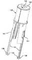
图1是本发明的自动注射器设备的立体装配图;Fig. 1 is the three-dimensional assembly drawing of automatic injector device of the present invention;
图2是图1的设备的立体局部分解图;Fig. 2 is a three-dimensional partial exploded view of the device of Fig. 1;
图3是图1的设备的完全分解图;Figure 3 is a complete exploded view of the device of Figure 1;
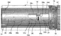
图4是图1的设备的纵向剖面;Fig. 4 is the longitudinal section of the equipment of Fig. 1;
图5是沿图4的直线V-V的图1的设备的纵向剖面;Fig. 5 is the longitudinal section along the equipment of Fig. 1 of the straight line V-V of Fig. 4;
图6是图1的设备中的剂量选择旋钮和活塞杆之间的连接的细节图;Figure 6 is a detailed view of the connection between the dose selection knob and the piston rod in the device of Figure 1;
图7是图6的细节的分解图;Figure 7 is an exploded view of the details of Figure 6;
图8是剂量选择旋钮的轴向立体图;Figure 8 is an axial perspective view of the dose selection knob;
图9是活塞杆的顶部的局部立体图;Fig. 9 is a partial perspective view of the top of the piston rod;
图10是图1的设备的外部主体的立体图;Figure 10 is a perspective view of the outer body of the device of Figure 1;
图11是图10的外部主体的纵向剖面;Figure 11 is a longitudinal section of the outer body of Figure 10;
图12是图10的外部主体的顶部的局部立体图;Figure 12 is a partial perspective view of the top of the outer body of Figure 10;
图13是本发明的设备的注射器组件的装配图;Figure 13 is an assembled view of the syringe assembly of the device of the present invention;
图14是本发明的设备中的凸轮套管和滑动套管之间的操作连接的立体图;Figure 14 is a perspective view of the operative connection between the cam bushing and the sliding bushing in the device of the present invention;
图15是滑动套管的轴向侧视图;Figure 15 is an axial side view of the sliding sleeve;
图16示出了沿图15的直线XVI – XVI的滑动套管的剖面图;Fig. 16 shows the sectional view of the sliding sleeve along the line XVI-XVI of Fig. 15;
图17是图15和图16的滑动套管的正视立体图;Figure 17 is a front perspective view of the sliding sleeve of Figures 15 and 16;
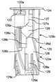
图18是本发明的设备中的凸轮套管的轴向侧视图;Figure 18 is an axial side view of the cam sleeve in the apparatus of the present invention;
图19是图18的凸轮套管的后视立体图;Figure 19 is a rear perspective view of the cam bushing of Figure 18;
图20是图18的凸轮套管的正视立体图;Figure 20 is a front perspective view of the cam bushing of Figure 18;
图21示出了准备起动用于第一剂量输送的设备;Figure 21 shows the device ready to start for first dose delivery;
图22a、22b和22c是本发明的设备在位置0(存储位置)和位置1(第一剂量准备位置)的细节图;Figures 22a, 22b and 22c are detailed views of the device of the present invention in position 0 (storage position) and position 1 (first dose preparation position);
图23a和23b示出了第一剂量输送步骤开始时和结束时的本发明的设备;Figures 23a and 23b show the device of the invention at the beginning and at the end of the first dose delivery step;
图24示出了重新覆盖和复位步骤时的设备;Figure 24 shows the device during the re-cover and reset steps;
图25a和25b示出了第二剂量选择步骤时的细节;Figures 25a and 25b show details during the second dose selection step;
图26a、26b和26c示出了第二剂量的输送的步骤;Figures 26a, 26b and 26c illustrate the steps of delivery of the second dose;
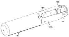
图27是本发明的自动注射器设备的第二实施例的立体装配图;Figure 27 is a perspective assembled view of a second embodiment of the automatic injector device of the present invention;
图28是图27的设备的立体局部分解图;Figure 28 is a three-dimensional partial exploded view of the device of Figure 27;
图29是图27的设备的完全分解图;Figure 29 is a fully exploded view of the device of Figure 27;
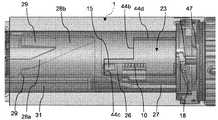
图30是图27的设备的纵向剖面;Figure 30 is a longitudinal section of the device of Figure 27;
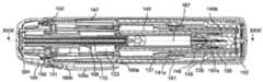
图31是沿图30的直线XXXI-XXXI的图27的设备的纵向剖面;Figure 31 is a longitudinal section of the device of Figure 27 along the line XXXI-XXXI of Figure 30;
图32是图27的设备中的剂量选择旋钮和活塞杆之间的连接的细节图;Figure 32 is a detail view of the connection between the dose selection knob and the piston rod in the device of Figure 27;
图33是图32的细节的分解图;Figure 33 is an exploded view of the detail of Figure 32;
图33a是活塞杆和棘轮之间的连接的细节剖面图;Figure 33a is a detailed cross-sectional view of the connection between the piston rod and the ratchet;
图34是活塞杆的顶部的局部立体图;Figure 34 is a partial perspective view of the top of the piston rod;
图35是剂量选择旋钮-棘轮组件的轴向立体图;Figure 35 is an axial perspective view of the dose selection knob-ratchet assembly;
图36是、形成图27的设备的外部主体的、底座-外部套管组件的分解立体图;36 is an exploded perspective view of the base-outer sleeve assembly forming the outer body of the apparatus of FIG. 27;
图37是图36的底座-外部套管组件的组装时的纵向剖面;Figure 37 is an assembled longitudinal section of the base-outer sleeve assembly of Figure 36;
图38是图36的底座的顶部的局部立体图;Figure 38 is a partial perspective view of the top of the base of Figure 36;
图39是图27的设备的注射器组件的装配图;Figure 39 is an assembled view of the syringe assembly of the device of Figure 27;
图40a、40b和40c分别是图27的设备中的滑动套管的侧视图、立体图以及沿图40a的直线40c-40c的纵向剖面图;Figures 40a, 40b and 40c are a side view, a perspective view and a longitudinal sectional view along the
图41a、41b和41c分别是图27的设备中的凸轮套管的侧视图、立体图以及反向的立体图;Figures 41a, 41b and 41c are side, perspective and reverse perspective views, respectively, of a cam bushing in the apparatus of Figure 27;
图42是图27的设备中的凸轮套管和滑动套管之间的操作连接的立体图;Figure 42 is a perspective view of the operative connection between the cam bushing and the sliding bushing in the apparatus of Figure 27;
图43a和43b是图27的设备在位置0(存储位置)和位置1(第一剂量准备位置)的细节图;Figures 43a and 43b are detailed views of the device of Figure 27 in position 0 (storage position) and position 1 (first dose preparation position);
图43c是图43b的第一剂量准备位置中的设备的横向剖面图;Figure 43c is a transverse sectional view of the device in the first dose preparation position of Figure 43b;
图44a和44b示出了处于起动点之前以及处于起动点的设备;Figures 44a and 44b show the device before and at the start point;
图45示出了重新覆盖步骤期间、输送第一剂量后的设备;Figure 45 shows the device after delivery of the first dose during the re-covering step;
图46a和46b分别示出了处于输送第一剂量后的存储位置的设备以及处于第二剂量准备位置并准备输送第二剂量的设备;Figures 46a and 46b show the device in the storage position after delivery of the first dose and the device in the second dose preparation position ready to deliver the second dose, respectively;
图47a、47b和47c是断裂的局部侧视立体图,分别示出了移向起动点期间、处于图46b的第二剂量准备位置的图27的设备以及在第二剂量起动步骤时的图27的设备;Figures 47a, 47b and 47c are fragmentary side perspective views showing, respectively, the device of Figure 27 in the second dose preparation position of Figure 46b during movement towards the start point, and the device of Figure 27 during the second dose start step equipment;
图48a、48b和48c分别是分离步骤之前、期间的本发明的第二实施例的设备的卡口连接的细节侧视图。Figures 48a, 48b and 48c are detailed side views of the bayonet connection of the device of the second embodiment of the invention before, during the separation step, respectively.
具体实施方式Detailed ways
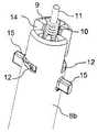
参照图1至图5,本发明的自动注射器设备包括:管状的外部主体1(特别是圆筒体),该外部主体1沿轴线X延伸,并包含大部分的设备组件。外部主体由两个同轴对齐的主体部分1a、1b形成,该两个主体部分1a、1b具有不同的直径并且由台阶1c隔开。可拆卸的端部盖子2的端部抵接于台阶1c,所述盖子2将设备的前端3遮盖。如后面所解释的,设备的另一端(后端)的附近形成或标记有角度间隔的参考标记,例如数字0、1、2,用于表示设备的静止或存储状态(0)以及两个操作状态(1、2)。在本说明书中,术语“前”、“后”及等同物涉及用于针头出口的设备的部件,分别是轴向相对的部件。还应当指出的是,在本说明书中总是参照一种用于两种剂量的药物的自动注射的设备,但应当理解的是,本发明还包括能够连续多次输送至少两种剂量的药物的设备,通过对设备的改变和改动,这对于本领域的技术人员来说是显而易见的。Referring to Figures 1 to 5, the autoinjector device of the present invention comprises: a tubular outer body 1 (in particular a cylinder) extending along axis X and containing most of the device components. The outer body is formed by two coaxially aligned
剂量选择旋钮4设于设备的后端,参考指标5设于剂量选择旋钮4上。剂量选择旋钮4能相对外部主体1轴向转动,以允许指标5与形成在其上的参考标记4对齐。The
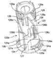
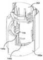
注射器组件(通常显示为6)被容纳在外部主体1内。如图13所示,注射器组件包括具有针头7a、针头护罩7b、圆筒7c以及内活塞止动器7d的药物预装式注射器7。活塞杆8的端部接合在圆筒7c内,该活塞杆8由、分为不同直径的两个部件8a、8b的、管状元件形成。部件8a具有横截面和端部,该横截面相对于圆筒7c的内部处于间隙状态,以便它能够在圆筒7c内滑动,该端部以这样一种方式成形,其由于轴向移动而与活塞止动器7d接合,以推进药物输送。活塞杆8的部件8b具有较大的直径,并设有内部径向肋条9,用于对准在活塞杆8内轴向延伸的动力弹簧10。动力弹簧10处于压缩状态,其一端抵靠活塞杆8的部件8a的闭合端,其另一端抵靠剂量选择旋钮4的底壁4a。动力弹簧10还围绕着支撑杆11,该支撑杆11从剂量选择旋钮4的同一底壁4a延伸至活塞杆8的部件8a的闭合端。径向肋条9与活塞杆的部件8a之间的以及与支撑杆11之间的动力弹簧10的布置有助于最大限度地减小动力弹簧10的屈曲。A syringe assembly (shown generally at 6 ) is housed within the
具体如图5至图9所示,在设备的存储状态,剂量选择旋钮4通过卡口连接而被连接至活塞杆8的部件8b。该卡口连接包括一对大致为L形的槽12以及一对固定夹13,该一对槽12在径向相对的位置沿周向形成在部件8b上,该一对固定夹13在径向相对的位置从剂量选择旋钮4向内突出。大致为L形的槽12包括沿周向延伸的固位槽分支12a以及沿轴向延伸至活塞杆8的部件8b的边缘的释放槽分支12b。当旋钮4上的指标5与参考标记0对齐时,两个固定夹13接合在槽12的相应的固位槽分支12a内,从而防止活塞杆8轴向滑动。由于活塞杆相对于旋钮4的轴向角位移,固定夹13在固位槽分支12a内滑动,直到它们开始与相应的释放槽分支12b对齐,从而使活塞杆8在动力弹簧10的作用下前进,其中该释放槽分支12b向后延伸至活塞杆8的部件8b的自由端,关于设备的操作将在后面说明。As shown in particular in Figures 5 to 9, in the stored state of the device, the
两个径向栓钉15的径向相对的部分从活塞杆的部件8b向外突出。如后面所解释的,在起动凸轮装置内滑动的两个径向栓钉11提供装置,以引导控制药物剂量输送的、活塞杆8的移动。Radially opposite parts of the two
如图4、图5和图6所示,剂量选择旋钮4设有周界槽16,位于外部主体1的后端的底部切口17能滑动地接合在周界槽16内,从而剂量选择旋钮4能相对于外部主体1转动,使得待输送的剂量允许被选择。As shown in Figure 4, Figure 5 and Figure 6, the
剂量选择旋钮4能只在一个方向转动,为此旋钮4和外部主体1之间的连接包括装置,该装置用于防止在与剂量选择的方向相反的方向转动。这些装置包括一对棘轮支脚18(参见图6和图7),该棘轮支脚18从旋钮4的边缘周向延伸。当旋钮4转动时,该棘轮支脚18适于能滑动地抵接在分度的斜坡表面19上,该斜坡表面19限定出两个斜坡台阶19a、19b(在图10和图11中仅示出一个)。当支脚18在斜坡表面19上滑动时,首先支脚18弯曲,然后一旦斜坡承受住压力(overcome),支脚18即会在此时位于斜坡的端部的斜坡台阶19a、19b上起动,紧靠斜坡台阶19a、19b,防止反向转动。止动肋条20也设于斜坡表面上,棘轮支脚18抵接于止动肋条20,以防止旋钮、在到达对应于第二剂量输送的位置后、进行任何进一步的转动。The
如图6至图8所示,一对径向相对的支脚21从剂量选择旋钮4的自由边缘、在活塞杆8的部件8b上轴向延伸,并接合在相应的底座22内,该底座22设于管状的支撑件23的后端,其中支撑件23在本说明书中被称为凸轮套管23(图18至图20)。底座22具有前端边缘22a,支脚21抵接于该前端边缘22a,以使得凸轮套管23与剂量选择旋钮4一体转动。定位凸缘24绕凸轮套管23的同一端向外延伸,其被设计为安置在相应的轮辋25上,从而防止相互轴向滑动,其中轮辋25位于外部主体1内并靠近外部主体1的后端。As shown in Figures 6 to 8, a pair of diametrically
如图18至图20所示,凸轮套管23设有两个具有不同的功能的分段:第一分段23a朝向前端,称为前段,第二分段23b朝向后端,称为后段。前段23a被可操作地连接至能滑动的套管30(见图14),该套管30的轴向滑动使得凸轮套管23有角度地移动,这将在稍后说明,而后段23b通过其径向栓钉15被可操作地连接至活塞杆8,并如上所述,连接至剂量选择旋钮4(具体参见图20)。As shown in FIGS. 18 to 20 , the
凸轮套管23在外部主体1内能够转动,并通过定位凸缘24保持轴向对齐。The
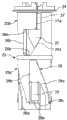
凸轮套管23的后段23b设有起动凸轮装置,以控制活塞杆8的移动。起动凸轮装置包括两个窗口26,该两个窗口26径向相对,至于它们的形状则相对轴向旋转轴对称,其通过相应的轴向延伸的通道27通向凸轮套管的后端边缘,其中通道27界定出第一剂量起动凸轮轨道27a。每个窗口由两个平行的周向侧部26a,26b界定,侧部26a,26b的两个端部由轴向侧部26c连接,与通道27相对的、侧部26b的另一端部由倾斜的侧部26d连接至通道27的一侧,其中侧部26d与轴向侧部26c相对。通道27在窗口26内的倾斜的侧部26d开放,并且轴向侧部26c形成第二剂量起动凸轮轨道。第一剂量起动凸轮轨道26c从第二剂量起动凸轮轨道27a有角度地间隔开。The
驱动凸轮装置28在凸轮套管23的前段23a的外表面上突出。驱动凸轮装置28由凸轮轮廓形成,该凸轮轮廓以等角度间距的方式在所述表面上重复四次。凸轮轮廓包括第一驱动凸轮轨道28a和第二驱动凸轮轨道28b,其中第一驱动凸轮轨道28a从凸轮套管23的端部延伸并相对于轴线X倾斜,为简单起见称为上升轨道;而第二驱动凸轮轨道28b从凸轮套管23的同一端延伸并和第一驱动凸轮轨道28a一样倾斜,为简单起见称为下降轨道。一对驱动销32被设计为依次在上升轨道28a和下降轨道28b上滑动。驱动销32从滑动套管30的两个径向相对的轴向驱动支脚31向内突出(图15至图17)。当压力作用被施加在滑动套管30的自由端3上时,凸轮套管23转动,其转动方向与上升轨道28a的倾斜方向相反。并且当压力作用停止时,一对驱动销32分别在上升轨道28a和下降轨道28b上滑动。On the outer surface of the
相关的悬臂支脚29被设于驱动凸轮装置28的下降轨道28b内,向内偏转以允许驱动销32的穿过。在设备的的存储状态,驱动销32抵接于位于悬臂支脚29的自由端的轴向锁定边缘29a(图4和图14),从而防止滑动套管30移向设备的后端。止动边缘28c,设于轴向锁定边缘29a的侧面,用作驱动销32的基台(abutment),以防止剂量选择旋钮4转动超过第一剂量输送和第二剂量输送的位置,这将在稍后说明。An associated
滑动套管30的位于驱动支脚31的相对的一侧的端部构成该设备的前端3,即该端部用于被带入而在注射部位与患者的皮肤接触。注射器7的针头7a从所述前端3突出并穿过位于前端3上的中心孔33。用于能滑动地容纳注射器7的中心弹簧凸台34从滑动套管30的前端3的内表面延伸。复位弹簧35卷绕着中心弹簧凸台34,其一端抵接于前端3的内表面,其另一端抵接于外部主体1的表面。The end of the sliding
驱动支脚31能滑动地与设于外部主体1内的轴向导轨36接合,从而滑动套管30能够仅在外部主体1内轴向移动。两个宽的轴向开口37被设于滑动套管30上,相对于驱动支脚31呈90°布置。轴向开口37与设于外部主体1上的相应的透明的检查窗口38轴向对齐,注射器7的圆筒7c通过窗口38是可见的,从而用户能够控制药物输送的条件。外部主体1上的用于复位弹簧35的抵接表面由所述检查窗口38的底壁38a构成。轴向开口37允许滑动套管30在外部主体1内根据所需的距离轴向行进,而不与窗口碰撞。The
一对装配夹39从滑动套管30的底部、在滑动套管30的轴向开口37内延伸,以与设于外部主体1的前端的相应的端部止动器40快速接合,从而允许滑动套管30在外部主体1内的组装,并防止其分离。A pair of
外部主体1的前端边缘抵接于一对弹性尖齿41的相应的前端边缘41a,该一对弹性尖齿41设于滑动套管30上的径向相对的两侧。这些尖齿的前端边缘41a是倾斜的,以承受滑动套管30的移动,并使得该移动仅由于适度地推力而可能发生,其中该推力使尖齿41向内偏转,直到外部主体1的边缘承受住(overcomes)尖齿41的最突出的端部。随后由尖齿41的释放所产生的移动有助于将注射器7的针头7a快速插入注射部位。The front edge of the
用于注射器7的管状壳体42设于外部主体1内,凸缘42a设于管状壳体42的一端,圆筒7c的相应凸缘7e安置在凸缘42a上。两个凸缘由固定夹43相互锁定,该固定夹43从外部主体1向内突出(参见图5、图11和图13)。A
如图11所示,导向装置44在外部主体1的内表面上突出,以控制活塞杆8的轴向移动,并以这种方式限制被输送的药物的容量。这些导向装置为台阶导轨,该台阶导轨在与轴线X垂直的平面上具有第一位置面44a、第二位置面44b以及止动凸缘44c。第一位置面44a的边缘通过第一轴向侧部44d而被连接至第二位置面44b,而第二位置面44b的边缘通过第二轴向侧部44e而被连接至止动凸缘44c。一对径向相对的台阶轨道形成在外部主体1上,其形状相对于轴向旋转轴对称。如后面所解释的,活塞杆8的径向栓钉15被设计用于随着凸轮套管23的转动而沿第一位置面44a滑动以及沿第二位置面44b滑动,并从第一位置面44a掉落至第二位置面44b以及从第二位置面44b掉落至止动凸缘44c,用于输送第一剂量的药物和第二剂量的药物,同时径向栓钉15沿第一轴向侧部44d移动以及相应地沿第二轴向侧部44e移动。As shown in FIG. 11 , guide means 44 protrude on the inner surface of the
针头护罩脱离器45(图2至图5)通过能卡扣接合的固定销45a而被可拆卸地固定至外部主体1,并且设有适于和针头护罩7b接合的内部管状手柄45b。从而在第一剂量被施用之前拉动针头护罩脱离器45,用户能够将针头护罩7b移除,并将针头7a释放以用于注射。A needle shield disconnector 45 (Figures 2-5) is detachably secured to the
以下是所使用的本发明的自动注射器设备的方法的说明。The following is a description of the method of use of the autoinjector device of the present invention.
在最初的存储状态下,动力弹簧10在活塞杆8的部件8a的闭合端与剂量选择旋钮4的底臂4a之间处于压缩状态。旋钮4和活塞杆8之间的卡口连接确保动力弹簧10处于压缩状态,直到第一剂量被选择。由于动力弹簧10在其一侧被布置在径向肋条9与活塞杆8的部件8a之间,且在其另一侧被布置在径向肋条9与支撑杆11之间,从而动力弹簧10的任何屈曲被防止出现。针头护罩7b被固定至注射器7,且针头护罩脱离器45被固定至针头护罩7b。盖子2被固定至外部主体1,并且由于驱动支脚31的驱动销32抵接于凸轮套管23的相应的锁定边缘29a,滑动套管30被阻止轴向移动。In the initial stored state, the
剂量选择旋钮4通过其外部周界槽16而被连接至外部主体1,位于外部主体1的后端的底部切口17能滑动地与周界槽16接合。一旦被安装,剂量选择旋钮4不能轴向移动,只能在一个方向上转动。转动方向由外部主体1上的参考标记指示:即指标5从位置0开始,当选择第一剂量时转动至位置1,然后当选择第二剂量时转动至位置2。The
在存储状态下,设备是“锁定的”,即滑动套管30不能在外部主体1内移动,因为滑动套管30的驱动支脚31抵接于凸轮套管23的轴向锁定边缘29a。该状态具体在图14中示出。如图21所示,当选择第一剂量(位置1)时,设备被解锁。由于剂量选择旋钮4的支脚21抵接于凸轮套管23的底座22的前端边缘22a上,通过转动剂量选择旋钮4,凸轮套管23由旋钮4的支脚21在相同的方向上推进。由于支脚31的驱动销32紧靠凸轮套管23上的凸轮轨道28的圆周止动边缘28d,剂量选择旋钮4不能转动超过位置1,直到第一剂量被输送。由于支脚31只能在外部主体1上的轴向导轨36内沿轴向前后移动,从而能滑动的套管30被阻止转动。In the storage state the device is "locked", ie the sliding
首先,用户必须向后滑动并取下端部盖子2,以露出针头护罩脱离器45。一旦第一剂量被输送后,当设备不使用时,端部盖子2必须被盖回。端部盖子2保护药物避免光照射,并防止颗粒进入而与设备的前端3接触。First, the user must slide back and remove the
为了进行第一次注射,用户必须取下针头护罩脱离器45。用这种方式,针头护罩7b也被取下,使针头7a保持为暴露状态,然而前端3仍然是稍稍嵌入,不容易被用户看见。为了使设备解锁并选择第一剂量的输送,用户将剂量选择旋钮4从位置0(存储状态)转动到位置1(第一剂量准备状态)。To perform the first injection, the user must remove the
剂量选择旋钮4从位置0到位置1的转动引起凸轮套管23的转动,从而悬臂支脚29的轴向锁定边缘29a相对于能滑动的套管30的支脚31的驱动销32移动,其中该驱动销32抵接圆周止动边缘28d,以防止旋钮4进一步转动,直到第一剂量被输送,并且驱动销32与凸轮轨道28的上升部28a对齐,以沿上升部28a自由移动。当他/她看见指标5与位置1的标记对齐,并感觉到由驱动销32接触凸轮轨道28所产生的转动阻力增加,且还听到由棘轮支脚18从斜坡表面19的台阶19a掉落所产生的“咔”的声音时,用户确认转动至位置1的过程结束。支脚18和台阶19a之间的对比度(contrast)防止旋钮4朝相反的方向转动。Rotation of the
通过握住(keeping)设备的外部主体1,用户将滑动套管30的前端3压向注射部位,设备被起动。由于弹性尖齿41与外部主体1的端部之间的对比度,滑动套管30在外部主体1内的移动产生阻力。由于其弹性以及倾斜的接触表面,弹性尖齿41受压力作用并完全向内偏转,以允许能够在外部主体1内滑动的滑动套管30穿过,让针头7a从其前端3突出,从而针头能够伸入注射部位。随后由弹性尖齿41的释放所产生的移动有助于将针头7a迅速插入注射部位。By keeping the
滑动套管30在外部主体1内的轴向移动引起凸轮套管23的转动,而后者通过摩擦也使得剂量选择旋钮4转动。为了防止旋钮4在第一剂量输送期间转动,剂量选择旋钮4和外部主体1之间设有临时止动装置,当棘轮支脚18的自由端从外部主体1的斜坡表面19的台阶19a脱落时,该临时止动装置相互接合。如图6、图11和图22c所示,本实施例中,临时止动装置包括外部主体的固定尖头(pips)46,该固定尖头46与旋钮4的相应的锁钩47(catches)接合。起动时,作用在剂量选择旋钮4上的转动力小于由尖头46提供的固定力。然而,用户能够提供的转动力比尖头的转动力大得多。因此,用户能够克服尖头的力,并转动旋钮4,使设备为第二剂量准备。Axial movement of the sliding
由于其径向栓钉15接合在相应的轴向通道27内,凸轮套管23的转动使得活塞杆8转动。转动几度后,由于旋钮4的固定夹13到达活塞杆8的相关的轴向分离槽分支12b,剂量选择旋钮4和活塞杆8之间的卡口连接分离,并且在动力弹簧10的作用下,活塞杆8被推进,以使径向栓钉15倚靠在外部主体1的台阶导轨44的第一位置面44a上。The rotation of the
当凸轮套管23继续转动时,在动力弹簧10的作用下,由第一剂量起动凸轮轨道27a推动的径向栓钉在第一位置面44a上滑动,直到它们到达其端部并从台阶导轨44的第二位置面44b脱落。该顺序在图23a和图23b中示出。所得的活塞杆8的轴向滑动引起第一剂量的输送。When the
输送第一剂量后,用户将设备从注射部位移除,针头7a从其中退出。复位弹簧35不再由前端3和注射部位之间的强制接触所阻碍,从而将滑动套管30沿轴向推进,进而重新覆盖针头。如图24所示,同时驱动支脚31的驱动销32在凸轮轨道28的下降部28b内向下滑动,将悬臂支脚29向内按压,直到设备恢复到“锁定”状态,其中驱动销32接触悬臂支脚29的自由端29a,并且滑动套管30的装配夹39再次与外部主体1的端部止动器40接合。由于被滑动套管30覆盖,针头7a此时被阻止进入。在该状态下,滑动套管30被阻止滑动,直到用户将剂量选择旋钮4转动至位置2。然后用户检查(recaps)设备。端部盖子2与外部主体1扣合,以牢固地固定在设备上。After delivering the first dose, the user removes the device from the injection site and the
如果需要第二剂量的输送,用户从设备取下盖子2,以能够进入滑动套管30。为了解锁设备,用户必须将剂量选择旋钮4从位置1(第一剂量准备位置)转动至位置2(第二剂量准备位置)。If delivery of a second dose is required, the user removes the
为此,用户必须克服旋钮4的锁钩47在外部主体1的固定尖头46上的反作用力。如图25a和图25b所示,旋钮4的支脚21开始在凸轮套管23的底座22上自由行进,直到它们到达前端边缘22a,以将凸轮套管23转动到位置2。同时,由于滑动套管30的驱动支脚31的驱动销32与凸轮轨道28的上升部28a对齐,凸轮套管30的转动使得设备解锁,同时一旦到达位置2,驱动销32接触圆周止动边缘28d,以防止旋钮4的进一步的转动。剂量选择旋钮4的反向转动由棘轮支脚18阻止,该棘轮支脚18卡接在斜坡表面19的台阶19a上。凸轮套管23的转动也使得径向栓钉15从窗口26内的轴向通道27的出口处重新定位至相对的轴向侧部26c,而它们在台阶导轨44的第二位置面44b上的位置是不变的。To do this, the user has to overcome the reaction force of the locking
通过握住(keeping)设备的外部主体1,用户将滑动套管30的前端3压向注射部位,设备被起动用于第二剂量的输送。由于弹性尖齿41与外部主体1的端部之间的对比度,滑动套管30在外部主体1内的移动产生阻力。由于其弹性以及倾斜的接触表面,弹性尖齿41受压力作用并完全向内偏转,以允许能够在外部主体1内滑动的滑动套管30穿过,让针头7a从其前端3突出,从而针头能够伸入注射部位。随后由弹性尖齿41的释放所产生的移动有助于将针头7a迅速插入注射部位。By keeping the
为了防止旋钮4的任何的进一步的转动,一旦到达位置2,当凸轮套管23的如下转动结束时,棘轮支脚18的基部接触分度斜坡19的止动肋条20。通过该接触,棘轮支脚19被固定在台阶19a与所述止动肋条20之间。To prevent any further rotation of the
当凸轮套管23继续转动时,在动力弹簧10的作用下,由窗口26的轴向侧部26c推动的径向栓钉15在第二位置面44b上滑动,直到它们到达所述面的端部,并在该端部它们从台阶导轨44的止动边缘44c脱落。该操作顺序在图26a和图26b中示出。所得的活塞杆8的轴向滑动引起第二剂量的输送。As the
值得注意的是,注射器圆筒内总是会剩余小容量的药物。事实上,台阶导轨44的止动边缘44c的位置以这样一种方式被设计,即当径向栓钉15到达止动边缘44c时,活塞止动器7d不接触圆筒7c的底部。这样,不仅预定量的药物的输送允许被控制,而且相对于注射器圆筒的内部长度的、任何制造误差被确保得到减小。因此,剂量精度得到改善。It is important to note that there will always be a small volume of drug remaining in the syringe barrel. In fact, the position of the
输送第二剂量后,用户将设备从注射部位移除,针头7a从其中退出。复位弹簧35不再由前端3和注射部位之间的强制接触所阻碍,从而将滑动套管30沿轴向推进,进而重新覆盖针头。正如第一剂量的输送结束时,同时驱动支脚31的驱动销32在驱动凸轮装置28的下降轨道28b内向下滑动,将悬臂支脚29向内按压,直到设备恢复到“锁定”状态,其中驱动销32接触悬臂支脚29的自由端29a,并且滑动套管30的装配夹39再次与外部主体1的端部止动器40接合。由于被滑动套管30覆盖,针头7a再次不能进入。然后在设备由医护人员处理/操作前,用户检查设备的端部盖子2。After delivering the second dose, the user removes the device from the injection site and the
尽管上述本发明的自动注射器设备配备有两个径向栓钉15,以引导活塞杆8的移动,该解决方案优选具有对称分布的力来作用于各组件上。很显然,在该解决方案中,在本发明的范围内也可仅设有一个径向栓钉15,作为其明显的变化。在这种情况下,台阶导向装置44、起动凸轮装置26、27以及驱动凸轮装置28将因此改变。Although the autoinjector device of the invention described above is equipped with two
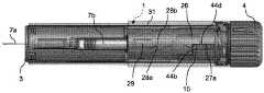
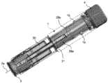
图27至图48示出了本发明的自动注射器设备的第二实施例,其特征在于一些部件的不同的结构,同时相对于上述的自动注射器设备保持基本上相同的操作。Figures 27 to 48 show a second embodiment of the autoinjector device of the present invention, characterized by a different configuration of some components, while maintaining substantially the same operation with respect to the autoinjector device described above.
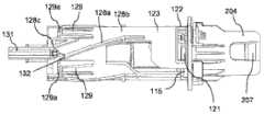
参照图27至图31,在本发明的第二实施例的自动注射器设备中,外部主体(通常表示为100)由两个不同的部件100a和100b组成,分别称为底座和外部套管,其能够彼此同轴固定。特别地,底座100a的一部分接合在套管100b内,并通过齿101a嵌入套管100b的相应的槽101b内而被固定在其上(见图36)。套管100b的外径大于底座100a的外径,从而形成台阶101c,可拆卸的端部盖子102的端部抵接于该台阶101c,所述盖子102遮盖设备的前端103。通过盖子固定齿101d嵌入形成在端部盖子102上的相应的槽102a内,可拆卸的端部盖子102被可拆卸地固定至底座100a。笔型夹100c沿套管100b的侧壁延伸,以将自动注射器设备悬挂至(例如)口袋。Referring to Figures 27 to 31 , in an autoinjector device according to a second embodiment of the present invention, the outer body (generally denoted 100 ) consists of two
如后面所解释的,外部主体100的另一端(后端)的附近形成或标记有角度间隔的参考标记,例如数字0、1、2,用于表示设备的静止或存储状态(0)以及两个操作状态(1、2)。As will be explained later, the vicinity of the other end (rear end) of the outer body 100 is formed or marked with angularly spaced reference marks, such as the
剂量选择旋钮104设于外部主体100的后端,参考指标105从剂量选择旋钮104轴向延伸。剂量选择旋钮104能相对外部主体100轴向转动,以允许指标105与形成在其上的参考标记对齐。A
在本发明的本实施例中,大致为杯状的棘轮204被容纳在剂量选择旋钮104的下方。棘轮204通过一对翼部205而与旋钮104为一体,该一对翼部205在旋钮内的径向相对的部分向内延伸,并设有切口206,该切口206用于与棘轮204的侧部轴向固定肋条204c卡扣配合(见图32和图33)。In this embodiment of the invention, a generally cup-shaped
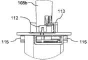
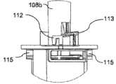
注射器组件(通常显示为106)被容纳在外部主体100内。如图39所示,注射器组件包括具有针头107a、针头护罩107b(还参见图29)、圆筒107c以及内活塞止动器107d的药物预装式注射器107。活塞杆108的端部接合在圆筒107c内,该活塞杆108由管状元件形成,该管状元件分为不同外径的两个部件,即前部108a和后部108b。前部108a具有横截面和端部,该横截面相对于圆筒107c的内部处于间隙状态,以便它能够在圆筒107c内滑动,该端部被配置用于由于轴向移动而与活塞止动器107d接合,以推进药物输送。活塞杆108的后部108b具有较大的直径。A syringe assembly (shown generally at 106 ) is housed within the outer body 100 . As shown in Figure 39, the syringe assembly includes a
活塞杆108的内径的尺寸适于容纳动力弹簧110,该动力弹簧110沿其整个长度轴向延伸。如图30和图31所示,动力弹簧110处于压缩状态,其一端抵靠活塞杆108的前部108a的闭合端,其另一端抵靠棘轮204的底壁204a。动力弹簧110还围绕着支撑杆111,该支撑杆111从设于棘轮204的底壁204a中心的固定孔204b延伸至活塞杆108的前部108a的闭合端。支撑杆111与活塞杆的前部108a的内壁之间的动力弹簧110的布置有助于最大限度地减小动力弹簧110的屈曲。The inner diameter of the
从剂量选择旋钮104的底壁向内延伸出一对径向相对的凸台109(图35),该凸台109被配置以与设于棘轮204的底部的相应的切口207接合,从而由用户施加在剂量选择旋钮104上的转动力矩通过凸台109和切口207传递到棘轮204,并从棘轮204传递到连接在其上的自动注射器设备组件,这将在下面说明。Extending inwardly from the bottom wall of
活塞杆108和棘轮204通过卡口连接耦合,该卡口连接使动力弹簧保持为压缩状态,直到设备被起动。参照图33至图35,卡口连接包括一对固定支脚112以及相应的驱动槽113,其中该固定支脚112在径向相对的部分从棘轮204向内突出,该驱动槽113从活塞杆108延伸并悬挂在固定支脚112上。保持稳定性通过由压缩的动力弹簧110所提供的轴向力保障,但连接不具有任何的周向约束,除了支脚112和槽113之间的相互摩擦。
两个径向栓钉115的径向相对的部分从活塞杆108的后部108b向外突出。如后面所解释的,具体如图32至图34所示,两个径向栓钉115提供装置,通过在起动凸轮装置内滑动,以引导控制药物剂量输送的、活塞杆108的移动。Radially opposite portions of the two
通过套管100b的向内凸缘150抵接在棘轮204的行进轮辋(running rim)151上,外部套管100b和旋钮-棘轮组件之间的连接(见图30和31)被形成,而旋钮104的自由边缘抵接在外部套管100b的后端边缘上。以这种方式,在接合过程期间,套管100b在选择旋钮104和棘轮204之间被控制(held captive)。定心肋条152从棘轮204上的行进轮辋151延伸,以提供棘轮204和套管100b之间的轴向对齐。The connection between the
剂量选择旋钮104能只在一个方向相对套管100b转动,为此棘轮204和套管100b之间的连接包括装置,该装置用于在旋钮到达一个操作位置后,防止在与剂量选择的方向相反的方向转动。这些装置包括一对弹性的棘轮支脚118(参见图35和图36),该棘轮支脚118从棘轮204的边缘周向延伸。当旋钮104转动时,该棘轮支脚118适于能滑动地抵接在套管100b的相应的防反向转动肋条119上(从图43c中可见)。当支脚118滑动时,首先由于肋条119的存在,支脚118弯曲,然后一旦肋条承受住压力(overcome),支脚118即会起动,紧靠肋条119,防止旋钮104的反向转动。止动肋条120(从图43c中可见)也沿套管100b的表面设置,棘轮204在止动肋条120上滑动。棘轮204的相应的突出部120a抵靠止动肋条120,以防止在旋钮到达与剂量输送相对应的位置后,进行任何进一步的向前转动。然而,突出部120a在适度的力的作用下必须偏转,以克服止动肋条120,并允许从一个操作位置通向另一个操作位置。The
如图33和图41a、图41b、图41c所示,一对径向相对的支脚121从棘轮204、在活塞杆108的部件108b上轴向延伸,并接合在管状的支撑件123的相应的槽122内,该槽122设于管状的支撑件123的后端,其中支撑件123在本说明书中被称为凸轮套管123。槽122具有前端边缘122a,支脚121的转动支脚121a抵接于该前端边缘122a,以使得凸轮套管123通过棘轮204而与剂量选择104一体转动。定位凸缘124(还参见图30和图31)绕凸轮套管123的同一端向外延伸,其被设计为用一个面安置在相应的轮辋125上,且另一个面安置在底座100a的后端边缘上,从而防止相互轴向滑动,其中轮辋125位于外部套管100b内并靠近外部套管100b的后端。As shown in Figure 33 and Figure 41a, Figure 41b, Figure 41c, a pair of diametrically
如图41a、图41b和图41c所示,凸轮套管123设有两个具有不同的功能的分段:第一分段123a朝向设备的前端,称为前段,第二分段123b朝向后端,称为后段。前段123a被可操作地连接至能滑动的套管130(见图30),该套管130的轴向滑动使得凸轮套管123有角度地移动,这将在稍后说明,而后段123b通过棘轮204被可操作地连接至活塞杆108的径向栓钉115,并如上所述,被连接至剂量选择旋钮104(具体参见图42)。As shown in Fig. 41a, Fig. 41b and Fig. 41c, the
凸轮套管123在外部套管100b内能够转动,并通过定位凸缘124保持轴向对齐。转动止动端部由位于凸缘124的外部边缘上的一对侧部肋条124a制成,该侧部肋条124a抵接于设于套管100b内的相应的基台(未示出)。
凸轮套管123的后段123b设有起动凸轮装置,以控制活塞杆108的移动。起动凸轮装置包括两个窗口126,该两个窗口126径向相对,至于它们的形状则相对轴向旋转轴对称,其通过相应的轴向延伸的通道127通向凸轮套管的后端边缘,其中通道127界定出第一剂量起动凸轮轨道127a。每个窗口126由两个平行的周向侧部126a,126b界定,侧部126a,126b的两个端部由轴向侧部126c连接,与通道127相对的、侧部126b的另一端部由倾斜的侧部126d连接至通道127的一侧,其中侧部126d与轴向侧部126c相对。通道127在窗口126内的倾斜的侧部126d开放,并且轴向侧部126c形成第二剂量起动凸轮轨道。第一剂量起动凸轮轨道127a从第二剂量起动凸轮轨道126c有角度地间隔开。本实施例中,侧部126b被置于窗口126内的加宽缺口的端部,以适应与组件特征的制造变化相关联的间隙和公差。The
驱动凸轮装置128在凸轮套管123的前段123a的外表面上突出。驱动凸轮装置128由凸轮轮廓形成,该凸轮轮廓以等角度间距的方式在所述表面上重复四次。凸轮轮廓包括第一驱动凸轮轨道128a和第二驱动凸轮轨道128b,其中第一驱动凸轮轨道128a从凸轮套管123的端部延伸并相对于轴线X倾斜,为简单起见称为上升轨道;而第二驱动凸轮轨道128b从凸轮套管123的同一端延伸并和第一驱动凸轮轨道128a一样倾斜,为简单起见称为下降轨道。一对驱动销132被设计为依次在上升轨道128a和下降轨道128b上滑动。驱动销132从滑动套管130的两个径向相对的轴向驱动支脚131向内突出(图40a、图40b和图40c)。当压力作用被施加在滑动套管130的自由端103上时,滑动开始,从而凸轮套管123转动,其转动方向与上升轨道128a的倾斜方向相反。并且当压力作用停止时,一对驱动销132分别在上升轨道128a和下降轨道128b上滑动。On the outer surface of the
相关的悬臂支脚129被设于驱动凸轮装置128的下降轨道128b内,向内偏转,以允许在驱动销在下降轨道内回程的期间,驱动销132穿过。在设备的的存储状态,驱动销132抵接于位于悬臂支脚129的自由端的轴向锁定边缘129a,从而防止滑动套管130移向设备的后端。止动边缘128c,设于轴向锁定边缘129a的侧面,用作驱动销132的基台(abutment),以防止棘轮204转动超过第一剂量输送和第二剂量输送的位置,这将在稍后说明。An associated
滑动套管130的位于驱动支脚131的相对的一侧的端部构成该设备的前端103,即该端部用于被带入而在注射部位与患者的皮肤接触。注射器107的针头107a从所述前端103突出并穿过位于前端103上的中心孔133。复位弹簧135的一端抵接于滑动套管130的前端103的内表面,其另一端抵接于底座100a的推进表面。在一侧,复位弹簧135由设于套管130内的定位肋条134引导。The end of the sliding
一对装配夹139从支脚131的端部向外延伸,以与沿底座100a形成的轴向导向槽147快速接合。当设备被组装时,支脚131偏转,从而允许装配夹139接合在槽147内以及滑动套管130沿轴向移动,防止设备分离。A pair of mounting
由于驱动支脚131能滑动地与设于底座100a内的轴向导向槽147接合,从而滑动套管130能够仅在外部主体100内沿轴向定位轨道136轴向移动,该轴向定位轨道136从底座100a的内表面向内突出。两个宽的轴向开口137被设于滑动套管130上,相对于驱动支脚131呈90°布置。轴向开口137与设于底座100a上的相应的透明的检查窗口138轴向对齐,注射器107的圆筒107c通过窗口138是可见的,从而用户能够控制药物输送的条件。底座100a上的用于复位弹簧135的抵接表面由所述检查窗口138的底壁138a构成。轴向开口137允许滑动套管130根据所需的距离轴向行进,而不与底座100a的窗口138碰撞。Since the driving
弹性尖齿141从滑动套管130的径向相对的部分突出,并具有倾斜的活动表面,从而当其紧靠、位于底座100a的轴向定位轨道136的前端的、相应的内部突出部141a时,能够承受滑动套管130的移动(参见图30和图37),并使得该移动仅由于适度地推力而可能发生,其中该推力使尖齿141向内偏转,以承受住(overcome)突出部141a。随后由尖齿141的释放所产生的移动有助于将注射器107的针头107a快速插入注射部位。The
用于注射器107的管状壳体142设于底座100a内,向内边缘142a设于管状壳体142的前端,圆筒107c的前端坐落于向内边缘142a上。在管状壳体142的另一端,圆筒107c具有突出的凸缘107e,凸轮套管123的前表面位于凸缘107e上(参见图30和图31)。A
如图37所示,用于径向栓钉115的导向装置144在底座100a的内表面上突出,以控制活塞杆108的轴向移动,并以这种方式限制被输送的药物的容量。这些导向装置为台阶导轨,该台阶导轨在与轴线X垂直的平面上具有位置面144a、和止动凸缘144c。位置面144a的边缘通过第一轴向侧部144d而被连接至底座100a的后端边缘,并通过第二轴向侧部144e而被连接至止动凸缘144c。一对径向相对的台阶轨道形成在底座100a的内表面上,其形状相对于轴向旋转轴对称。如后面所解释的,活塞杆108的径向栓钉115被设计用于在输送第一剂量时,从位于底座100a的后端的位置跳下至位置面144a上,从而栓钉115的相对轴向位置由固定支脚113和驱动槽112之间的卡口部件的连接所限定,并且栓钉115随着凸轮套管123的转动而在位置面144a上滑动,最后在输送第二剂量的药物时,从位置面144a掉落至止动凸缘144c,同时径向栓钉115沿第一轴向侧部144d移动以及相应地沿第二轴向侧部144e移动。As shown in Figure 37, guides 144 for the radial pegs 115 protrude on the inner surface of the
针头护罩脱离器145通过能卡扣接合的固定销145a而被可拆卸地固定至滑动套管130,该固定销145a紧靠位于套管130的前端的凸缘。针头护罩脱离器145设有内部管状手柄145b,插入件146被布置在内部管状手柄145b内,用于通过固定挂钩(未示出)卡入橡胶针头护罩而接合在针头护罩107b上。从而在第一剂量被施用之前拉动针头护罩脱离器145,用户能够将针头护罩107b移除,并将针头107a释放以用于注射。The
本发明的第二实施例的自动注射器设备的操作被描述如下。如上所述,该操作基本上和本发明的先前所描述的实施例的操作相同。参照图42至图48,这些图中的虚线149(当存在时)表示底座100a的前端的位置。The operation of the automatic injector device of the second embodiment of the present invention is described as follows. As mentioned above, the operation is substantially the same as that of the previously described embodiment of the present invention. Referring to Figures 42-48, the dashed
在最初的存储状态下,动力弹簧110在活塞杆108的部件108a的闭合端与棘轮204的底臂204a之间处于压缩状态,其中棘轮204与剂量选择旋钮104为一体。棘轮204和活塞杆108之间的卡口连接确保动力弹簧110处于压缩状态,直到第一剂量被起动。由于动力弹簧110被布置在活塞杆108的部件108b与支撑杆111之间,从而动力弹簧110的任何屈曲被防止出现。In the initial stored state, the
针头护罩107b被固定至注射器107,且针头护罩脱离器145通过插入件146而被固定至针头护罩107b。盖子102被固定至底座100a,并且由于驱动支脚131的驱动销132抵接于凸轮套管123的相应的锁定边缘129a,滑动套管130被阻止轴向移动。The
由于套管100b在相互为一体的旋钮104和棘轮204之间被控制(held captive),从而剂量选择旋钮104被连接至外部主体100。一旦被安装,由剂量选择旋钮104和棘轮204形成的组件不能轴向移动,只能在一个方向上转动。转动方向由外部主体100上的参考标记指示:即指标105从位置0开始,当选择第一剂量时转动至位置1,然后当选择第二剂量时转动至位置2。The
在存储状态下,设备是“锁定的”,即滑动套管130不能在外部主体100内移动,因为滑动套管130的驱动支脚131抵接于凸轮套管123的轴向锁定边缘129a。该状态具体在图42和图43a中示出。如图43b所示,当选择第一剂量(位置1)时,设备被解锁。由于棘轮204的支脚121由它们的转动支脚121a抵接于凸轮套管123的槽122的前端边缘122a上,通过转动剂量选择旋钮104,凸轮套管123由棘轮204的支脚121在相同的方向上推进。由于支脚131的驱动销132紧靠凸轮套管123上的凸轮轨道128的止动边缘128c,剂量选择旋钮104不能转动超过位置1,直到第一剂量被输送。由于支脚131只能在底座100a上的轴向导向槽147内沿轴向前后移动,从而能滑动的套管130被阻止转动。In the storage state, the device is "locked", ie the sliding
必须指出的是,如图43a所示,在静止位置,起动凸轮轨道127a和相应的径向栓钉115之间存在设计间隙Y。棘轮204的支脚121的转动支脚121a和凸轮套管123的槽122的相应的前端边缘122a之间存在程度较低(lower extent)的设计间隙Z。当用户转动剂量选择旋钮104时,一开始,他/她必须克服由套管100b的止动肋条120所提供的反向阻力,其中止动肋条120抵靠棘轮204的突出部120a(图43c)。小转动有必要做到这一点,其使转动支脚121a接触前端边缘122a,而剩余的间隙在起动凸轮轨道127a和相应的径向栓钉115之间仍然存在。It must be noted that there is a design gap Y between the starting
首先,用户必须向后滑动并取下端部盖子102,以露出针头护罩脱离器145。一旦第一剂量被输送后,当设备不使用时,端部盖子102必须被盖回。端部盖子102保护药物避免光照射,并防止颗粒进入而与设备的前端103接触。First, the user must slide back and remove the
为了进行第一次注射,用户必须取下针头护罩脱离器145。用这种方式,插入件146以及针头护罩107b也被取下,使针头107a保持为暴露状态,然而前端103仍然是稍稍嵌入,不容易被用户看见。为了使设备解锁并选择第一剂量的输送,用户将剂量选择旋钮104从位置0(存储状态)转动到位置1(第一剂量准备状态)。To perform the first injection, the user must remove the
剂量选择旋钮104从位置0到位置1的转动引起凸轮套管123的转动,从而悬臂支脚129的轴向锁定边缘129a相对于能滑动的套管130的支脚131的驱动销132移动,其中该驱动销132抵接于止动边缘128c,以防止旋钮104进一步转动,直到第一剂量被输送,并且驱动销132与凸轮轨道128的上升部128a对齐,以沿上升部128a自由移动(参见图43b和图45)。当他/她看见指标105与位置1的标记对齐,并感觉到由驱动销132接触凸轮轨道128所产生的转动阻力增加,且还听到由棘轮支脚118从相关的肋条119掉落所产生的“咔”的声音时,用户确认转动至位置1的过程结束。支脚118和相关的肋条119之间的对比度(contrast)防止旋钮104的反向转动,而任何的正向转动由套管100b的止动肋条120与棘轮204的突出部120a之间的基台所阻碍(图43c)。Rotation of the
通过握住(keeping)设备的外部主体100,用户将滑动套管130的前端103压向注射部位,设备被起动。由于滑动套管130的弹性尖齿141与底座100a的内部突出部141a之间的对比度,滑动套管130在外部主体100内的移动产生阻力。由于其弹性以及倾斜的接触表面,弹性尖齿141受压力作用并完全向内偏转,同时承受住(overcoming)突出部141a,以允许能够在底座100a内滑动的滑动套管130穿过,让针头107a从其前端103突出,从而针头能够伸入注射部位。随后由弹性尖齿141的释放所产生的移动有助于将针头107a迅速插入注射部位(图44a)。By holding the outer body 100 of the device, the user presses the
滑动套管130在外部主体100内的轴向移动引起凸轮套管123的转动,而后者通过摩擦也使得棘轮204和剂量选择旋钮104转动。为了防止旋钮104在第一剂量输送期间转动,棘轮204和套管100b之间设有临时止动装置,当棘轮支脚118的自由端从套管100b的肋条119脱落时,该临时止动装置相互接合。如图43c所示,本实施例中,临时止动装置包括套管100b的止动肋条120,该止动肋条120抵靠棘轮204的相应的突出部120a。起动时,作用在棘轮204上的转动力小于由止动肋条120提供的固定力。然而,用户能够提供的转动力比止动肋条120的转动力大得多。因此,用户能够克服肋条的力,并转动旋钮104,使设备为第二剂量准备。Axial movement of the sliding
由于其径向栓钉115接合在相应的轴向通道127内,由起动凸轮轨道127a推动,凸轮套管123的转动使得活塞杆108转动。随着活塞杆108的驱动槽113在棘轮204的相应的固定支脚112上滑动,直到槽113从支脚112分离,从而活塞杆108的角位移使得卡口连接分离。该顺序在图49中示出。此时动力弹簧110,不再由卡口连接固定,将其弹性推力施加在活塞杆108上,该活塞杆108在凸轮套管123内向前移动,直到径向栓钉115(在轴向通道127内滑动)倚靠在套管100b的台阶导轨144的位置面144a上(参见图47a)。所得的活塞杆108的轴向滑动引起第一剂量的输送。Rotation of the
输送第一剂量后,用户将设备从注射部位移除,针头107a从其中退出。复位弹簧135不再由前端103和注射部位之间的强制接触所阻碍,从而将滑动套管130沿轴向推进,进而重新覆盖针头。如图46a所示,同时驱动支脚131的驱动销132在凸轮轨道128的下降部128b内向下滑动,将悬臂支脚129向内按压,直到设备恢复到“锁定”状态,其中驱动销132接触悬臂支脚129的自由端129a,并且滑动套管130的装配夹139再次与底座100a的轴向导轨136内的端部止动器140a接合。After delivering the first dose, the user removes the device from the injection site and the
由于被滑动套管130覆盖,针头107a此时被阻止进入。在该状态下,滑动套管130被阻止滑动,直到用户将剂量选择旋钮104转动至位置2。然后用户检查设备。端部盖子102与外部主体100扣合,以牢固地固定在底座100a上。The
如果需要第二剂量的输送,用户从设备取下盖子102,以能够进入滑动套管130。为了解锁设备,用户必须将剂量选择旋钮104从位置1(第一剂量准备位置)转动至位置2(第二剂量准备位置)(参见图46a和图46b)。If delivery of a second dose is required, the user removes the
为此,用户必须克服套管100b的止动肋条120在棘轮204的突出部120a上的反作用力。突出部120a的偏转允许旋钮104转动。如图46a和图46b所示,棘轮204的支脚121开始在凸轮套管123的槽122上自由行进,直到转动支脚121a到达前端边缘122a,以将凸轮套管123转动到位置2。本实施例中,到达位置2也如到达位置1时,由“咔”的声音通知。To do this, the user must overcome the reaction force of the stop rib 120 of the
由于滑动套管130的驱动支脚131的驱动销132与凸轮轨道128的上升部128a对齐,凸轮套管123的转动使得设备解锁,同时一旦到达位置2,驱动销132接触止动边缘128c,以防止旋钮104的进一步的转动。剂量选择旋钮104的反向转动由棘轮支脚118阻止,该棘轮支脚118卡接在套管100b的突出部119上。凸轮套管123的转动也使得径向栓钉115从窗口126内的轴向通道127的出口处重新定位至相对的轴向侧部126c,而它们在台阶导轨144的位置面144a上的位置是不变的(图46b和图47a)。Since the
通过握住设备的外部主体100,用户将滑动套管130的前端103压向注射部位,设备被起动用于第二剂量的输送。由于滑动套管130的弹性尖齿141与底座100a的内部突出部141a之间的对比度,滑动套管130在底座100a内的移动产生阻力,该移动由支脚131的驱动销132将滑动套管130推向上升轨道128a而产生。由于其弹性以及倾斜的接触表面,弹性尖齿141受压力作用并完全向内偏转,承受住(overcoming)突出部141a,以允许能够在底座100a内滑动的滑动套管130穿过,让针头107a从其前端103突出,从而针头能够伸入注射部位。随后由弹性尖齿141的释放所产生的移动有助于将针头107a迅速插入注射部位。由于其定位凸缘124沿轴向抵靠套管100b的轮辋125,由驱动销132所产生的推力不会引起凸轮套管123的任何显著的轴向移动。By holding the outer body 100 of the device, the user presses the
为了防止旋钮104的任何的进一步的转动,一旦到达位置2,当凸轮套管123的如下转动结束时,棘轮支脚118的自由端抵靠止动肋条119,从而防止旋钮104的反向转动,而正向转动由套管100b的止动肋条120和棘轮204的突出部120a之间的对比度所阻碍(图43c)。To prevent any further rotation of the
当凸轮套管123继续转动时,在动力弹簧110的作用下,由窗口126的轴向侧部126c推动的径向栓钉115在台阶导轨144的位置面144a上滑动,直到它们到达所述面的端部,并在该端部它们从台阶导轨144的止动边缘144c脱落。该操作顺序在图47a至图47c中示出。所得的活塞杆108的轴向滑动引起第二剂量的输送。When the
输送第二剂量后,用户将设备从注射部位移除,针头107a从其中退出。复位弹簧135不再由前端103和注射部位之间的强制接触所阻碍,从而将滑动套管130沿轴向推进,进而重新覆盖针头。正如第一剂量的输送结束时,同时驱动支脚131的驱动销132在驱动凸轮装置128的下降轨道128b内向下滑动,将悬臂支脚129向内按压,直到设备恢复到“锁定”状态,其中驱动销132接触悬臂支脚129的自由端129a,并且滑动套管130的装配夹139再次与底座100a的轴向导轨136内的端部止动器140a接合。由于被滑动套管130覆盖,针头107a再次不能进入。然后在设备由医护人员处理/操作前,用户检查设备的端部盖子102。After the second dose has been delivered, the user removes the device from the injection site and the
本发明的自动注射器设备适用于溶液中的药物(尤其是肾上腺素)的输送。The autoinjector device of the present invention is suitable for the delivery of medicaments in solution, especially epinephrine.
特别地,可使用本发明的设备进行施用的、肾上腺素的剂量优选每次的输送剂量为0.05毫克-0.5毫克(如果考虑两种剂量,为 0.1毫克-1毫克)。In particular, the dose of epinephrine that can be administered using the device of the invention is preferably in the range of 0.05 mg to 0.5 mg (0.1 mg to 1 mg if two doses are considered) per delivered dose.
每次输送的剂量优选为0.05毫克、0.10毫克、0.15毫克、0.30毫克和0.50毫克。The doses delivered are preferably 0.05 mg, 0.10 mg, 0.15 mg, 0.30 mg and 0.50 mg per delivery.
上述剂量根据肾上腺素溶液的浓度,优选为0.05毫克/毫升-0.5毫克/毫升,特别优选0.05毫克/毫升、0.1毫克/毫升、0.16毫克/毫升、0.3毫克/毫升和0.5毫克/毫升的浓度。The above-mentioned dosage is based on the concentration of epinephrine solution, preferably 0.05 mg/ml-0.5 mg/ml, particularly preferably 0.05 mg/ml, 0.1 mg/ml, 0.16 mg/ml, 0.3 mg/ml and 0.5 mg/ml.
Claims (31)
Translated fromChineseApplications Claiming Priority (3)
| Application Number | Priority Date | Filing Date | Title |
|---|---|---|---|
| ITFI2011A000194 | 2011-09-08 | ||
| IT000194AITFI20110194A1 (en) | 2011-09-08 | 2011-09-08 | MEDICINE DOSES SELF-INJECTION DEVICE |
| PCT/EP2012/067438WO2013034651A1 (en) | 2011-09-08 | 2012-09-06 | Device for automatic injection of drug doses |
Publications (2)
| Publication Number | Publication Date |
|---|---|
| CN103764205Atrue CN103764205A (en) | 2014-04-30 |
| CN103764205B CN103764205B (en) | 2016-08-31 |
Family
ID=44898625
Family Applications (1)
| Application Number | Title | Priority Date | Filing Date |
|---|---|---|---|
| CN201280043367.0AActiveCN103764205B (en) | 2011-09-08 | 2012-09-06 | Devices for automatic injection of drug doses |
Country Status (35)
| Country | Link |
|---|---|
| US (1) | US9017293B2 (en) |
| EP (1) | EP2753382B1 (en) |
| JP (1) | JP5972378B2 (en) |
| KR (1) | KR101965559B1 (en) |
| CN (1) | CN103764205B (en) |
| AP (1) | AP3487A (en) |
| AR (1) | AR087820A1 (en) |
| AU (1) | AU2012306332B2 (en) |
| BR (1) | BR112014005382B1 (en) |
| CA (1) | CA2842747C (en) |
| CL (1) | CL2014000564A1 (en) |
| CU (1) | CU24166B1 (en) |
| CY (1) | CY1117313T1 (en) |
| DK (1) | DK2753382T3 (en) |
| EA (1) | EA024822B1 (en) |
| ES (1) | ES2563989T3 (en) |
| GE (1) | GEP20166466B (en) |
| GT (1) | GT201400040A (en) |
| HR (1) | HRP20160242T1 (en) |
| HU (1) | HUE027133T2 (en) |
| IL (1) | IL231396A (en) |
| IT (1) | ITFI20110194A1 (en) |
| ME (1) | ME02361B (en) |
| MX (1) | MX341284B (en) |
| MY (1) | MY167129A (en) |
| PE (1) | PE20141619A1 (en) |
| PH (1) | PH12014500189A1 (en) |
| PL (1) | PL2753382T3 (en) |
| RS (1) | RS54665B1 (en) |
| SI (1) | SI2753382T1 (en) |
| SM (1) | SMT201600063B (en) |
| TN (1) | TN2014000028A1 (en) |
| UA (1) | UA110146C2 (en) |
| WO (1) | WO2013034651A1 (en) |
| ZA (1) | ZA201400728B (en) |
Cited By (8)
| Publication number | Priority date | Publication date | Assignee | Title |
|---|---|---|---|---|
| CN105517599A (en)* | 2013-07-09 | 2016-04-20 | 赛诺菲-安万特德国有限公司 | auto injector |
| CN106110443A (en)* | 2016-07-20 | 2016-11-16 | 苏州翰尔西医疗器械开发有限公司 | A kind of syringe |
| CN106999679A (en)* | 2014-12-05 | 2017-08-01 | 诺和诺德股份有限公司 | Drive mechanism for injection device |
| CN109475700A (en)* | 2016-07-27 | 2019-03-15 | 艾斯曲尔医疗公司 | Cap assembly for drug delivery devices |
| CN110072589A (en)* | 2016-12-13 | 2019-07-30 | 贝克顿·迪金森公司 | Safety needle device |
| US10646654B2 (en) | 2014-03-28 | 2020-05-12 | Sanofi-Aventis Deutschland Gmbh | Autoinjector triggered by skin contact |
| CN113082393A (en)* | 2021-04-14 | 2021-07-09 | 郑州万辉医疗设备有限公司 | Automatic needle inserting and assisting device for injection needle |
| CN118903605A (en)* | 2024-07-22 | 2024-11-08 | 安徽宏宇五洲医疗器械股份有限公司 | Needle-punching-preventing auxiliary injection device |
Families Citing this family (46)
| Publication number | Priority date | Publication date | Assignee | Title |
|---|---|---|---|---|
| EP2399635A1 (en) | 2010-06-28 | 2011-12-28 | Sanofi-Aventis Deutschland GmbH | Auto-injector |
| WO2014104391A1 (en) | 2012-12-28 | 2014-07-03 | Jfeスチール株式会社 | Production method for grain-oriented electrical steel sheet and primary recrystallized steel sheet for production of grain-oriented electrical steel sheet |
| US10232118B2 (en) | 2013-04-10 | 2019-03-19 | Sanofi | Drive assembly for a drug delivery device |
| US11801075B2 (en)* | 2013-05-29 | 2023-10-31 | Spinal Simplicity, Llc | Instrument for inserting an interspinous process implant |
| EP2823838A1 (en)* | 2013-07-09 | 2015-01-14 | Sanofi-Aventis Deutschland GmbH | Autoinjector |
| EA032285B1 (en) | 2013-08-08 | 2019-05-31 | Глобал Био Терапьютикс, Инк. | Injection device for minimally invasive procedures and uses thereof |
| WO2015021443A1 (en) | 2013-08-08 | 2015-02-12 | Global Bio Therapeutics Usa, Inc. | Clamp device for minimally invasive procedures and uses thereof |
| GB2521212B (en)* | 2013-12-13 | 2016-07-27 | Owen Mumford Ltd | Selectable dose injection device |
| EP2886144A1 (en)* | 2013-12-20 | 2015-06-24 | Sanofi-Aventis Deutschland GmbH | Drug delivery device |
| US10441725B2 (en)* | 2014-05-28 | 2019-10-15 | Sanofi-Aventis Deutschland Gmbh | Dose setting mechanism for a drug delivery device and drug delivery device |
| TW201611853A (en) | 2014-07-01 | 2016-04-01 | Sanofi Sa | Injection device |
| KR101983199B1 (en) | 2014-11-27 | 2019-05-28 | 제이에프이 스틸 가부시키가이샤 | Method for manufacturing grain-oriented electrical steel sheet |
| BR112017011464A2 (en)* | 2014-12-08 | 2018-02-27 | Genentech, Inc. | drug delivery devices and methods of manufacturing a device |
| CA3009221A1 (en) | 2014-12-23 | 2016-06-30 | Automed Pty Ltd | Delivery apparatus, system and associated methods |
| US20170246395A1 (en)* | 2016-02-29 | 2017-08-31 | Shl Group Ab | Delivery Device |
| US11612700B2 (en) | 2016-02-29 | 2023-03-28 | Shl Medical Ag | Delivery device |
| US20170246400A1 (en)* | 2016-02-29 | 2017-08-31 | Shl Group Ab | Delivery Device |
| US11065390B2 (en) | 2016-02-29 | 2021-07-20 | Shl Medical Ag | Automatic delivery device with end of injection indication device |
| EP4035711B1 (en)* | 2016-03-15 | 2025-06-04 | Amgen Inc. | Reducing probability of glass breakage in drug delivery devices |
| ES2944914T3 (en) | 2016-03-16 | 2023-06-27 | Lilly Co Eli | Medication injection device with automatic needle retraction after injection |
| JP6617203B2 (en)* | 2016-03-16 | 2019-12-11 | イーライ リリー アンド カンパニー | Trigger assembly for automatic drug injection device |
| US10420591B2 (en) | 2016-04-14 | 2019-09-24 | Spinal Simplicity, Llc | Interspinous implant insertion instrument with staggered path implant deployment mechanism |
| GB201607491D0 (en)* | 2016-04-29 | 2016-06-15 | Owen Mumford Ltd | Injection devices |
| US10549044B2 (en) | 2016-06-09 | 2020-02-04 | Becton, Dickinson And Company | Spacer assembly for drug delivery system |
| US10751476B2 (en) | 2016-06-09 | 2020-08-25 | Becton, Dickinson And Company | Actuator assembly for drug delivery system |
| US10603445B2 (en) | 2016-06-09 | 2020-03-31 | Becton, Dickinson And Company | Needle actuator assembly for drug delivery system |
| US10792432B2 (en) | 2016-06-09 | 2020-10-06 | Becton, Dickinson And Company | Drive assembly and spacer for drug delivery system |
| EP3492613B1 (en) | 2016-07-29 | 2020-09-02 | JFE Steel Corporation | Hot-rolled steel sheet for grain-oriented magnetic steel sheet and production method therefor, and production method for grain-oriented magnetic steel sheet |
| JP7111809B2 (en) | 2017-10-16 | 2022-08-02 | ベクトン・ディキンソン・アンド・カンパニー | Spacer assembly for drug delivery device |
| US20220118184A1 (en)* | 2019-01-04 | 2022-04-21 | Novo Nordisk A/S | A shield trigger mechanism and an injection device with a shield trigger mechanism |
| EP3952957A1 (en)* | 2019-04-09 | 2022-02-16 | Battelle Memorial Institute | Autoinjectors having advanced release and sound features |
| WO2021045212A1 (en) | 2019-09-06 | 2021-03-11 | Jfeスチール株式会社 | Grain-oriented electromagnetic steel plate and production method therefor |
| KR102283889B1 (en)* | 2019-09-27 | 2021-08-03 | 주식회사 케이 | Needless injector |
| EP4076598B1 (en)* | 2019-12-18 | 2025-08-06 | Novo Nordisk A/S | Fixed dose injection device |
| WO2021122200A1 (en) | 2019-12-18 | 2021-06-24 | Novo Nordisk A/S | Fixed dose injection device |
| JP7656611B2 (en)* | 2019-12-18 | 2025-04-03 | ノボ・ノルデイスク・エー/エス | Drug delivery device for delivering a predetermined fixed dose - Patents.com |
| JP2023506854A (en)* | 2019-12-18 | 2023-02-20 | ノボ・ノルデイスク・エー/エス | fixed dose injection device |
| US11065392B1 (en) | 2020-03-25 | 2021-07-20 | Action Medical Technologies, Llc | Apparatuses and methods for injecting medicaments |
| US12005244B2 (en) | 2020-03-27 | 2024-06-11 | Medivena Sp. Z O.O. | Needle-based device based on direct wing-based coupling of a needle shield to a barrel thereof and safety mechanism implemented therein |
| EP4138961B1 (en) | 2020-04-23 | 2024-06-05 | Novo Nordisk A/S | Activatable drug delviery device with safety assembly |
| US11957542B2 (en) | 2020-04-30 | 2024-04-16 | Automed Patent Holdco, Llc | Sensing complete injection for animal injection device |
| KR102842753B1 (en)* | 2020-05-15 | 2025-08-06 | 바이오콘 바이오로직스 리미티드 | Autoinjector device for drug delivery |
| US11759576B2 (en) | 2020-06-05 | 2023-09-19 | Action Medical Technologies, Llc | Parenteral injection apparatus |
| IL312017A (en)* | 2021-10-11 | 2024-06-01 | Congruence Medical Solutions Llc | Automatic injection device |
| EP4173656A1 (en) | 2021-10-27 | 2023-05-03 | medmix Switzerland AG | Needle guard, drug delivery device and method for manufacturing |
| WO2024204818A1 (en) | 2023-03-29 | 2024-10-03 | Jfeスチール株式会社 | Method for producing grain-oriented electrical steel sheet, production facility line for grain-oriented electrical steel sheet, and hot rolled sheet for grain-oriented electrical steel sheet |
Citations (4)
| Publication number | Priority date | Publication date | Assignee | Title |
|---|---|---|---|---|
| CN88102557A (en)* | 1987-05-08 | 1988-12-14 | 斯普卢特-海伦公司 | Injection pen |
| US6575939B1 (en)* | 1998-02-04 | 2003-06-10 | Sanofi-Synthelabo | Device for automatic injection of a dose of medicinal product |
| CN1679978A (en)* | 1999-04-16 | 2005-10-12 | 法马西雅公司 | Injector device and method for its operation |
| WO2009040602A1 (en)* | 2007-09-25 | 2009-04-02 | Becton Dickinson France | Autoinject0r with deactivating means moveable by a safety shield |
Family Cites Families (13)
| Publication number | Priority date | Publication date | Assignee | Title |
|---|---|---|---|---|
| US4031893A (en) | 1976-05-14 | 1977-06-28 | Survival Technology, Inc. | Hypodermic injection device having means for varying the medicament capacity thereof |
| GB9310163D0 (en) | 1993-05-18 | 1993-06-30 | Owen Mumford Ltd | Improvements relating to injection devices |
| US5540664A (en) | 1993-05-27 | 1996-07-30 | Washington Biotech Corporation | Reloadable automatic or manual emergency injection system |
| US6808507B2 (en)* | 2002-05-10 | 2004-10-26 | Cambridge Biostability Ltd. | Safety injectors |
| US20050027255A1 (en) | 2003-07-31 | 2005-02-03 | Sid Technologies, Llc | Automatic injector |
| JP4934051B2 (en) | 2004-11-24 | 2012-05-16 | エスホーエル メディカル アクチボラゲット | Injection device |
| ES2557778T3 (en) | 2004-11-24 | 2016-01-28 | Group Ab Shl | Injection device |
| FR2905273B1 (en) | 2006-09-06 | 2009-04-03 | Becton Dickinson France Soc Pa | AUTOMATIC INJECTION DEVICE WITH TIMING MEANS. |
| ES2365931T3 (en)* | 2006-12-13 | 2011-10-13 | Shl Group Ab | AUTOMATIC INJECTOR |
| JP5264916B2 (en) | 2007-09-25 | 2013-08-14 | ベクトン・ディキンソン・フランス・エス.エー.エス. | Automatic syringe with deactivating means movable by safety shield |
| CA2711653C (en)* | 2008-01-23 | 2016-07-05 | Novo Nordisk A/S | Device for injecting apportioned doses of liquid drug |
| US8376993B2 (en) | 2008-08-05 | 2013-02-19 | Antares Pharma, Inc. | Multiple dosage injector |
| GB0913385D0 (en) | 2009-07-31 | 2009-09-16 | Medical House The Plc | Improved autoinjector |
- 2011
- 2011-09-08ITIT000194Apatent/ITFI20110194A1/enunknown
- 2012
- 2012-06-09UAUAA201403597Apatent/UA110146C2/enunknown
- 2012-09-06MYMYPI2014000237Apatent/MY167129A/enunknown
- 2012-09-06USUS14/342,754patent/US9017293B2/enactiveActive
- 2012-09-06RSRS20160140Apatent/RS54665B1/enunknown
- 2012-09-06CACA2842747Apatent/CA2842747C/enactiveActive
- 2012-09-06KRKR1020147009127Apatent/KR101965559B1/enactiveActive
- 2012-09-06SISI201230472Tpatent/SI2753382T1/enunknown
- 2012-09-06PHPH1/2014/500189Apatent/PH12014500189A1/enunknown
- 2012-09-06BRBR112014005382-0Apatent/BR112014005382B1/enactiveIP Right Grant
- 2012-09-06MXMX2014002750Apatent/MX341284B/enactiveIP Right Grant
- 2012-09-06APAP2014007489Apatent/AP3487A/enactive
- 2012-09-06CUCU20140030Apatent/CU24166B1/enactiveIP Right Grant
- 2012-09-06MEMEP-2016-42Apatent/ME02361B/enunknown
- 2012-09-06CNCN201280043367.0Apatent/CN103764205B/enactiveActive
- 2012-09-06PLPL12754014Tpatent/PL2753382T3/enunknown
- 2012-09-06GEGEAP201213438Apatent/GEP20166466B/enunknown
- 2012-09-06AUAU2012306332Apatent/AU2012306332B2/enactiveActive
- 2012-09-06PEPE2014000305Apatent/PE20141619A1/enactiveIP Right Grant
- 2012-09-06EAEA201490586Apatent/EA024822B1/enunknown
- 2012-09-06JPJP2014528976Apatent/JP5972378B2/enactiveActive
- 2012-09-06HUHUE12754014Apatent/HUE027133T2/enunknown
- 2012-09-06HRHRP20160242TTpatent/HRP20160242T1/enunknown
- 2012-09-06EPEP12754014.4Apatent/EP2753382B1/enactiveActive
- 2012-09-06DKDK12754014.4Tpatent/DK2753382T3/enactive
- 2012-09-06WOPCT/EP2012/067438patent/WO2013034651A1/enactiveApplication Filing
- 2012-09-06ESES12754014.4Tpatent/ES2563989T3/enactiveActive
- 2012-09-07ARARP120103324Apatent/AR087820A1/enactiveIP Right Grant
- 2014
- 2014-01-20TNTNP2014000028Apatent/TN2014000028A1/enunknown
- 2014-01-30ZAZA2014/00728Apatent/ZA201400728B/enunknown
- 2014-03-04GTGT201400040Apatent/GT201400040A/enunknown
- 2014-03-06ILIL231396Apatent/IL231396A/enactiveIP Right Grant
- 2014-03-07CLCL2014000564Apatent/CL2014000564A1/enunknown
- 2016
- 2016-02-26CYCY20161100161Tpatent/CY1117313T1/enunknown
- 2016-03-03SMSM201600063Tpatent/SMT201600063B/enunknown
Patent Citations (4)
| Publication number | Priority date | Publication date | Assignee | Title |
|---|---|---|---|---|
| CN88102557A (en)* | 1987-05-08 | 1988-12-14 | 斯普卢特-海伦公司 | Injection pen |
| US6575939B1 (en)* | 1998-02-04 | 2003-06-10 | Sanofi-Synthelabo | Device for automatic injection of a dose of medicinal product |
| CN1679978A (en)* | 1999-04-16 | 2005-10-12 | 法马西雅公司 | Injector device and method for its operation |
| WO2009040602A1 (en)* | 2007-09-25 | 2009-04-02 | Becton Dickinson France | Autoinject0r with deactivating means moveable by a safety shield |
Cited By (19)
| Publication number | Priority date | Publication date | Assignee | Title |
|---|---|---|---|---|
| CN105517599B (en)* | 2013-07-09 | 2019-12-03 | 赛诺菲-安万特德国有限公司 | auto injector |
| US11541188B2 (en) | 2013-07-09 | 2023-01-03 | Sanofi-Aventis Deutschland Gmbh | Autoinjector |
| US12156996B2 (en) | 2013-07-09 | 2024-12-03 | Sanofi-Aventis Deutschland Gmbh | Autoinjector |
| US12161847B2 (en) | 2013-07-09 | 2024-12-10 | Sanofi-Aventis Deutschland Gmbh | Autoinjector |
| CN105517599A (en)* | 2013-07-09 | 2016-04-20 | 赛诺菲-安万特德国有限公司 | auto injector |
| US10646654B2 (en) | 2014-03-28 | 2020-05-12 | Sanofi-Aventis Deutschland Gmbh | Autoinjector triggered by skin contact |
| US11660396B2 (en) | 2014-03-28 | 2023-05-30 | Sanofi-Aventis Deutschland Gmbh | Autoinjector |
| US12233244B2 (en) | 2014-03-28 | 2025-02-25 | Sanofi-Aventis Deutschland Gmbh | Autoinjector |
| CN106999679A (en)* | 2014-12-05 | 2017-08-01 | 诺和诺德股份有限公司 | Drive mechanism for injection device |
| CN106110443B (en)* | 2016-07-20 | 2022-07-22 | 昆山翰尔西医疗器械有限公司 | Syringe |
| CN106110443A (en)* | 2016-07-20 | 2016-11-16 | 苏州翰尔西医疗器械开发有限公司 | A kind of syringe |
| CN109475700B (en)* | 2016-07-27 | 2021-04-13 | 艾斯曲尔医疗公司 | Cap assembly for a medicament delivery device |
| CN109475700A (en)* | 2016-07-27 | 2019-03-15 | 艾斯曲尔医疗公司 | Cap assembly for drug delivery devices |
| CN110072589A (en)* | 2016-12-13 | 2019-07-30 | 贝克顿·迪金森公司 | Safety needle device |
| CN110072589B (en)* | 2016-12-13 | 2021-09-03 | 贝克顿·迪金森公司 | Safety needle device |
| CN113082393B (en)* | 2021-04-14 | 2022-07-22 | 郑州万辉医疗设备有限公司 | Automatic needle inserting and assisting device for injection needle |
| CN113082393A (en)* | 2021-04-14 | 2021-07-09 | 郑州万辉医疗设备有限公司 | Automatic needle inserting and assisting device for injection needle |
| CN118903605A (en)* | 2024-07-22 | 2024-11-08 | 安徽宏宇五洲医疗器械股份有限公司 | Needle-punching-preventing auxiliary injection device |
| CN118903605B (en)* | 2024-07-22 | 2025-03-18 | 安徽宏宇五洲医疗器械股份有限公司 | A needle-stick-proof auxiliary injection device |
Also Published As
Similar Documents
| Publication | Publication Date | Title |
|---|---|---|
| CN103764205B (en) | Devices for automatic injection of drug doses | |
| CN103957963B (en) | Device for automatic injection of two doses of medicine | |
| US11141536B2 (en) | Injection device with dosing control means | |
| CN102917742B (en) | Device for automatic injection of two doses of medicine | |
| JP6139697B2 (en) | Drug delivery device | |
| KR101543942B1 (en) | Medicament delivery device | |
| US10709841B2 (en) | Injection device | |
| KR20200053630A (en) | Auto-injector device | |
| CN102770173A (en) | Automatic injection device with delay mechanism including dual function biasing member | |
| CN114340702A (en) | Drug delivery device with needle carrier | |
| HK1195880B (en) | Device for automatic injection of drug doses | |
| NZ623615B2 (en) | Device for automatic injection of drug doses | |
| OA16748A (en) | Device for automatic injection of drug doses. |
Legal Events
| Date | Code | Title | Description |
|---|---|---|---|
| C06 | Publication | ||
| PB01 | Publication | ||
| C10 | Entry into substantive examination | ||
| SE01 | Entry into force of request for substantive examination | ||
| C14 | Grant of patent or utility model | ||
| GR01 | Patent grant |