CN103764035A - Hybrid multi-row detector and flat panel imaging system - Google Patents
Hybrid multi-row detector and flat panel imaging systemDownload PDFInfo
- Publication number
- CN103764035A CN103764035ACN201280040969.0ACN201280040969ACN103764035ACN 103764035 ACN103764035 ACN 103764035ACN 201280040969 ACN201280040969 ACN 201280040969ACN 103764035 ACN103764035 ACN 103764035A
- Authority
- CN
- China
- Prior art keywords
- detector
- source
- image
- flat
- panel detector
- Prior art date
- Legal status (The legal status is an assumption and is not a legal conclusion. Google has not performed a legal analysis and makes no representation as to the accuracy of the status listed.)
- Granted
Links
Images


Classifications
- A—HUMAN NECESSITIES
- A61—MEDICAL OR VETERINARY SCIENCE; HYGIENE
- A61B—DIAGNOSIS; SURGERY; IDENTIFICATION
- A61B6/00—Apparatus or devices for radiation diagnosis; Apparatus or devices for radiation diagnosis combined with radiation therapy equipment
- A61B6/02—Arrangements for diagnosis sequentially in different planes; Stereoscopic radiation diagnosis
- A61B6/03—Computed tomography [CT]
- A61B6/032—Transmission computed tomography [CT]
- A—HUMAN NECESSITIES
- A61—MEDICAL OR VETERINARY SCIENCE; HYGIENE
- A61B—DIAGNOSIS; SURGERY; IDENTIFICATION
- A61B6/00—Apparatus or devices for radiation diagnosis; Apparatus or devices for radiation diagnosis combined with radiation therapy equipment
- A—HUMAN NECESSITIES
- A61—MEDICAL OR VETERINARY SCIENCE; HYGIENE
- A61B—DIAGNOSIS; SURGERY; IDENTIFICATION
- A61B6/00—Apparatus or devices for radiation diagnosis; Apparatus or devices for radiation diagnosis combined with radiation therapy equipment
- A61B6/42—Arrangements for detecting radiation specially adapted for radiation diagnosis
- A61B6/4266—Arrangements for detecting radiation specially adapted for radiation diagnosis characterised by using a plurality of detector units
- A—HUMAN NECESSITIES
- A61—MEDICAL OR VETERINARY SCIENCE; HYGIENE
- A61B—DIAGNOSIS; SURGERY; IDENTIFICATION
- A61B6/00—Apparatus or devices for radiation diagnosis; Apparatus or devices for radiation diagnosis combined with radiation therapy equipment
- A61B6/02—Arrangements for diagnosis sequentially in different planes; Stereoscopic radiation diagnosis
- A61B6/03—Computed tomography [CT]
- A—HUMAN NECESSITIES
- A61—MEDICAL OR VETERINARY SCIENCE; HYGIENE
- A61B—DIAGNOSIS; SURGERY; IDENTIFICATION
- A61B6/00—Apparatus or devices for radiation diagnosis; Apparatus or devices for radiation diagnosis combined with radiation therapy equipment
- A61B6/42—Arrangements for detecting radiation specially adapted for radiation diagnosis
- A61B6/4208—Arrangements for detecting radiation specially adapted for radiation diagnosis characterised by using a particular type of detector
- A61B6/4233—Arrangements for detecting radiation specially adapted for radiation diagnosis characterised by using a particular type of detector using matrix detectors
- A—HUMAN NECESSITIES
- A61—MEDICAL OR VETERINARY SCIENCE; HYGIENE
- A61B—DIAGNOSIS; SURGERY; IDENTIFICATION
- A61B6/00—Apparatus or devices for radiation diagnosis; Apparatus or devices for radiation diagnosis combined with radiation therapy equipment
- A61B6/44—Constructional features of apparatus for radiation diagnosis
- A61B6/4405—Constructional features of apparatus for radiation diagnosis the apparatus being movable or portable, e.g. handheld or mounted on a trolley
- G—PHYSICS
- G21—NUCLEAR PHYSICS; NUCLEAR ENGINEERING
- G21K—TECHNIQUES FOR HANDLING PARTICLES OR IONISING RADIATION NOT OTHERWISE PROVIDED FOR; IRRADIATION DEVICES; GAMMA RAY OR X-RAY MICROSCOPES
- G21K1/00—Arrangements for handling particles or ionising radiation, e.g. focusing or moderating
- G21K1/02—Arrangements for handling particles or ionising radiation, e.g. focusing or moderating using diaphragms, collimators
Landscapes
- Health & Medical Sciences (AREA)
- Life Sciences & Earth Sciences (AREA)
- Engineering & Computer Science (AREA)
- Medical Informatics (AREA)
- Physics & Mathematics (AREA)
- High Energy & Nuclear Physics (AREA)
- Heart & Thoracic Surgery (AREA)
- Animal Behavior & Ethology (AREA)
- Optics & Photonics (AREA)
- Pathology (AREA)
- Radiology & Medical Imaging (AREA)
- Biomedical Technology (AREA)
- Biophysics (AREA)
- Molecular Biology (AREA)
- Surgery (AREA)
- Nuclear Medicine, Radiotherapy & Molecular Imaging (AREA)
- General Health & Medical Sciences (AREA)
- Public Health (AREA)
- Veterinary Medicine (AREA)
- Pulmonology (AREA)
- Theoretical Computer Science (AREA)
- Mathematical Physics (AREA)
- Spectroscopy & Molecular Physics (AREA)
- General Engineering & Computer Science (AREA)
- Apparatus For Radiation Diagnosis (AREA)
Abstract
Description
Translated fromChinese技术领域technical field
本公开涉及对受验者成像,且特定地涉及使用具有多-行检测器和平板检测器的成像系统来生成受验者的图像。The present disclosure relates to imaging a subject, and in particular to generating images of a subject using an imaging system having a multi-row detector and a flat panel detector.
背景技术Background technique
本部分提供与本公开有关的背景信息,不必定是现有技术。This section provides background information related to the present disclosure which is not necessarily prior art.
诸如人类患者之类的受验者可选择或被要求进行外科手术来修正或加强的患者的解剖构造。解剖构造的增强可包括各种手术,诸如骨的移动或增强、可植入设备的插入、或其它合适的手术。外科医生可使用可由诸如磁共振成像(MRI)系统、计算机断层扫描(CT)系统、透视(如,C型臂成像系统)、或其它合适的成像系统之类的成像系统得到的患者图像,来对受验者执行手术。A subject, such as a human patient, may select or be required to undergo surgery to modify or enhance the patient's anatomy. Augmentation of the anatomy may include various procedures, such as movement or augmentation of bone, insertion of implantable devices, or other suitable procedures. Using patient images available from imaging systems such as magnetic resonance imaging (MRI) systems, computed tomography (CT) systems, fluoroscopy (e.g., C-arm imaging systems), or other suitable imaging systems, the surgeon may Surgery is performed on the subject.
患者的图像有助于外科医生执行手术,包括规划手术或执行手术。外科医生可选择表示患者的二维图像或三维图像。当执行手术时,通过允许外科医生在无需移除覆盖的组织(包括皮肤或肌肉组织)的情况下查看患者的解剖构造,这些图像可辅助外科医生用微创技术执行手术。Images of the patient assist the surgeon in performing the procedure, including planning the procedure or performing the procedure. The surgeon may choose to represent the two-dimensional image or the three-dimensional image of the patient. When performing surgery, these images assist surgeons in performing procedures with minimally invasive techniques by allowing them to view the patient's anatomy without removing overlying tissue, including skin or muscle tissue.
发明内容Contents of the invention
本部分提供本公开的一般概览,且不是本公开的全部范围或所有特征的全面性公开。This section provides a general overview of the disclosure, and is not a comprehensive disclosure of the full scope or all features of the disclosure.
根据各个实施例,提供了一种用成像系统来捕获受验者图像数据的系统。系统可包括完全环形地包围受验者的至少一部分的机架,以及置于机架内且相对于机架可移动的源。该源可响应于信号而输出至少一个脉冲。该系统可包括位于机架内和相对于机架可移动的多-行检测器。可将该多-行检测器放置为与该源对准,以检测由该源发射的至少一个脉冲,并且基于所检测到的至少一个信号来设置该多-行检测器数据。该系统可包括置于机架内且相对于机架可移动的平板检测器。可使平板检测器放置为与该源对准,以检测由该源发射的至少一个脉冲,并且基于所检测到的至少一个信号来设置平板检测器数据。该系统可包括图像捕获控制模块,该模块设置该源的信号并确定使用多-行检测器和平板检测器中的哪一个来检测由该源发射的至少一个脉冲。According to various embodiments, a system for capturing image data of a subject with an imaging system is provided. The system can include a gantry that completely annularly surrounds at least a portion of the subject, and a source positioned within the gantry and movable relative to the gantry. The source may output at least one pulse in response to the signal. The system may include a multi-row detector located within and movable relative to the frame. The multi-row detector can be positioned in alignment with the source to detect at least one pulse emitted by the source, and set the multi-row detector data based on the detected at least one signal. The system may include a flat panel detector disposed within and movable relative to the frame. A flat panel detector can be placed in alignment with the source to detect at least one pulse emitted by the source and set flat panel detector data based on the at least one detected signal. The system can include an image capture control module that sets the signal of the source and determines which of the multi-row detector and the flat panel detector to use to detect at least one pulse emitted by the source.
进一步提供一种用成像系统捕获受验者的图像数据的方法。该方法可包括提供可用于完全环形地包围受验者的至少一部分的机架,该成像系统包括置于机架内并耦合到相对机架可移动的转子的源、多-行检测器、以及平板检测器。该方法可包括接收至少一个用户输入,该用户输入提供用于捕获受验者的一部分的图像数据的请求,并且基于该用户输入来确定使用多-行检测器和平板检测器中的哪一个来捕获图像数据。该方法还可包括移动多-行检测器和平板检测器中被选中者与源对准,并且用该源输出至少一个脉冲。该方法可包括用多-行检测器和平板检测器中被选中者接收该至少一个脉冲,并且基于检测器接收到的该至少一个脉冲来输出受验者的图像。A method of capturing image data of a subject with an imaging system is further provided. The method may include providing a gantry operable to completely annularly surround at least a portion of a subject, the imaging system comprising a source disposed within the gantry and coupled to a rotor movable relative to the gantry, a multi-row detector, and flat panel detector. The method may include receiving at least one user input providing a request for capturing image data of a portion of the subject, and determining, based on the user input, which of a multi-row detector and a flat panel detector to use for Capture image data. The method may also include moving a selected one of the multi-row detector and the flat panel detector into alignment with the source, and outputting at least one pulse with the source. The method may include receiving the at least one pulse with a selected one of the multi-row detector and the flat panel detector, and outputting an image of the subject based on the at least one pulse received by the detector.
还提供了一种用成像系统捕获受验者的图像数据的方法。该方法可包括提供可用于完全环形地包围受验者的至少一部分的机架,该成像系统包括置于机架内并且耦合到相对机架可移动的转子的源、多-行检测器、以及平板检测器。该方法可包括接收至少一个用户输入,该用户输入提供捕获受验者的一部分的图像数据的请求,并且基于该用户输入来确定使用高对比度图像捕获还是使用低对比度图像捕获来捕获该图像数据。该方法还可包括移动多-行检测器与源对准而执行低对比度图像捕获,以及移动平板检测器与源对准而执行高对比度图像捕获。该方法可包括用该源输出至少一个脉冲,并且用多-行检测器和平板检测器中被选中者接收该至少一个脉冲。该方法还可包括基于检测器接收到的至少一个脉冲来重建受验者的图像,并把重建的受验者图像显示在显示器上。Also provided is a method of capturing image data of a subject with an imaging system. The method may include providing a gantry operable to completely annularly surround at least a portion of the subject, the imaging system comprising a source disposed within the gantry and coupled to a rotor movable relative to the gantry, a multi-row detector, and flat panel detector. The method may include receiving at least one user input providing a request to capture image data of a portion of the subject, and determining, based on the user input, whether to capture the image data using high contrast image capture or low contrast image capture. The method may also include moving the multi-row detector in alignment with the source for low-contrast image capture, and moving the flat-panel detector in alignment with the source for high-contrast image capture. The method may include outputting at least one pulse with the source, and receiving the at least one pulse with a selected one of a multi-row detector and a flat panel detector. The method may also include reconstructing an image of the subject based on the at least one pulse received by the detector, and displaying the reconstructed image of the subject on the display.
从此处提供的描述中,进一步的应用领域会变得显而易见。本概要中的描述和特定示例示例仅是说明性目的,而并非旨在限制本公开的范围。Further areas of application will become apparent from the description provided herein. The description and specific examples in this summary are intended for purposes of illustration only and are not intended to limit the scope of the present disclosure.
附图说明Description of drawings
此处描述的附图仅作为所选实施例而非全部可能的实现,且不旨在限制本公开的范围。The drawings described herein represent only selected embodiments and not all possible implementations, and are not intended to limit the scope of the present disclosure.
图1是根据各个实施例的、包括多-行检测器和平板检测器的、手术室中的示例性成像系统的环境图;1 is an environmental diagram of an exemplary imaging system in an operating room including a multi-row detector and a flat panel detector, according to various embodiments;
图2是与图1的成像系统一起使用的示例性计算系统的示意图;2 is a schematic diagram of an exemplary computing system for use with the imaging system of FIG. 1;
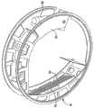
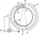
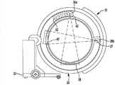
图3A是根据第一示例性配置的、包括多-行检测器和平板检测器的、图1的成像系统的机架的示意图;3A is a schematic diagram of a chassis of the imaging system of FIG. 1 including a multi-row detector and a flat panel detector according to a first exemplary configuration;
图3B是根据第二示例性配置的、包括多-行检测器和平板检测器的、图1的成像系统的机架的示意图;3B is a schematic diagram of a chassis of the imaging system of FIG. 1 including a multi-row detector and a flat panel detector according to a second exemplary configuration;
图4A是与多-行检测器对准的、图1的成像系统的源的示意图;Figure 4A is a schematic diagram of a source of the imaging system of Figure 1 aligned with a multi-row detector;
图4B是与平板检测器对准的、图1的成像系统的源的示意图;Figure 4B is a schematic diagram of a source of the imaging system of Figure 1 aligned with a flat panel detector;
图5是示出用于实现根据各个实施例的图像捕获控制模块的系统的简化框图;Figure 5 is a simplified block diagram illustrating a system for implementing an image capture control module according to various embodiments;
图6是示出由图5的图像捕获控制模块执行的示例性控制系统的数据流图;6 is a data flow diagram illustrating an exemplary control system executed by the image capture control module of FIG. 5;
图7是示出由图像捕获控制模块执行的示例性方法的流程图;以及7 is a flowchart illustrating an exemplary method performed by an image capture control module; and
图8是示例性成像系统的示意图,该系统包括与多-行检测器对准的第一源以及与平板检测器对准的第二源。8 is a schematic diagram of an exemplary imaging system including a first source aligned with a multi-row detector and a second source aligned with a flat panel detector.
具体实施方式Detailed ways
实质上,下述描述只是示例性的。应该理解,在整个附图中,相应的参考标记表示相似的或相应的部件和特性。如上所述,本教示涉及成像设备,诸如在美国Louisville,CO具有商业地位的Medtronic Navigation有限公司销售的O型臂
参考图1,在手术室或手术房间10中,诸如用户12之类的用户可对患者14进行手术。在进行手术时,用户12可使用成像系统16来捕获患者14的图像数据用于进行手术。所捕获的患者14的图像数据可包括用X-射线成像系统(包括这里所公开的那些)捕获的二-维(2D)投影。然而,要理解,还可生成体积模型的2D正向投影,也如这里所公开的那样。Referring to FIG. 1 , in an operating room or room 10 , a user such as user 12 may operate on a patient 14 . While performing a procedure, user 12 may use
在一个示例中,可使用所捕获的图像数据来生成模型。该模型可以是基于使用包括代数迭代技术之类的各种技术捕获的图像数据所生成的三-维(3D)体积模型,也如这里进一步讨论的那样。可在显示设备20上显示所显示的图像数据18,且此外,可在与成像计算系统32相关联的显示设备32a上显示图像数据18,如这里下面更详细地讨论。所显示的图像数据18可以是2D图像、3D图像、或时间变化的四维图像。所显示的图像数据18还可包括捕获的图像数据、生成的图像数据、两者、或两种类型图像数据的合并。In one example, captured image data can be used to generate a model. The model may be a three-dimensional (3D) volumetric model generated based on image data captured using various techniques, including algebraic iteration techniques, as also discussed further herein. Displayed
要理解,可捕获患者14的所捕获的图像数据作为2D投影,例如,用X-射线成像系统。然后可使用2D投影来重建患者14的3D体积图像数据。同样,可从3D体积图像数据中生成理论的或正向的2D投影。因此,要理解,图像数据可以是2D投影或3D投影的一个或两者。It is understood that the captured image data of patient 14 may be captured as a 2D projection, for example, with an x-ray imaging system. The 2D projections can then be used to reconstruct the 3D volumetric image data of patient 14 . Likewise, theoretical or forward 2D projections can be generated from 3D volumetric image data. Thus, it is to be understood that the image data may be one or both of 2D projections or 3D projections.
显示设备20可以是计算系统22的一部分。计算系统22可包括各种计算机可读介质。计算机可读介质可以是计算系统22可访问的任何可用的介质,并且可包括易失性和非-易失性介质、以及可移动和不可移动介质两者。作为示例,并非限制,计算机可读介质可包括计算机存储介质和通信介质。存储介质包括,但是不限于,RAM、ROM、EEPROM、闪存、或其它存储器技术、CD-ROM、数字多功能盘(DVD)、或其它光盘存储器、盒式磁带、磁带、磁盘存储器、或其它磁存储器件、或可用来存储计算机可读指令、软件、数据结构、程序模块与其它数据且计算系统22可访问的任何其它介质。可直接访问计算机可读介质,或通过诸如因特网之类的网络来访问计算机可读介质。
在一个示例中,计算系统22可包括诸如键盘之类的输入设备24、以及可与计算系统22结合在一起的一个或多个处理器26(一个或多个处理器可包括多-处理核处理器、微处理器等)。输入设备24可包括能使用户与计算系统22接口的任何合适设备,诸如触摸垫、触摸笔、触摸屏、键盘、鼠标、摇杆、跟踪球、无线鼠标、音频控制、或它们的组合。此外,尽管这里描述和示出计算系统22为包括与显示设备20分立的输入设备24,但是计算系统22可包括触摸垫、或平板计算设备,且此外,计算系统22可结合在成像计算系统32中或是与成像系统16相关联的成像计算系统32的一部分。可在计算系统22和显示设备20之间提供用于数据通信的连接28,以允许驱动显示设备20来示出图像数据18。In one example, computing system 22 may include an input device 24, such as a keyboard, and one or more processors 26 that may be integrated with computing system 22 (the one or more processors may include multi-processing core processing devices, microprocessors, etc.). Input device 24 may include any suitable device that enables a user to interface with computing system 22, such as a touch pad, stylus, touch screen, keyboard, mouse, joystick, trackball, wireless mouse, audio controls, or combinations thereof. Additionally, although computing system 22 is described and shown herein as including input device 24 separate from
成像系统16可包括在美国Louisville,CO具有商业地位的MedtronicNavigation有限公司销售的O型臂
O型臂
继续参考图1,机架34可定义成像系统16的等中心。在这个方面,通过机架34的中心线C1可定义成像系统16的等中心或中心。一般而言,可沿机架34的中心线C1放置患者14,以致患者14的纵轴可与成像系统16的等中心对准。With continued reference to FIG. 1 ,
参考图2,提供了示出成像计算系统32的示例性实施例的图,其中一些或所有的组件可结合与本公开的教示一起使用。成像计算系统32可包括各种计算机可读介质。计算机可读介质可以是成像计算系统32可访问的任何可用的介质,并且包括易失性和非-易失性介质、可移动和不可移动介质两者。作为示例,而非限制,计算机可读介质可包括计算机存储介质和通信介质。存储介质包括,但不限于,RAM、ROM、EEPROM、闪存、或其它存储器技术、CD-ROM、数字多功能盘(DVD)、或其它光盘存储器、盒式磁带、磁带、磁盘存储器、或其它磁存储器件、或可用来存储计算机可读指令、软件、数据结构、程序模块与其它数据且成像计算系统32可访问的何其它介质。可直接访问计算机可读介质,或通过诸如因特网之类的网络访问计算机可读介质。Referring to FIG. 2 , a diagram is provided illustrating an exemplary embodiment of an imaging computing system 32 in which some or all of the components may be used in conjunction with the teachings of the present disclosure. Imaging computing system 32 may include various computer readable media. Computer readable media can be any available media that can be accessed by imaging computing system 32 and includes both volatile and non-volatile media, removable and non-removable media. By way of example, and not limitation, computer readable media may comprise computer storage media and communication media. Storage media include, but are not limited to, RAM, ROM, EEPROM, flash memory, or other memory technology, CD-ROM, digital versatile disk (DVD), or other optical disk storage, cassette tape, magnetic tape, magnetic disk storage, or other magnetic memory device, or any other medium that can be used to store computer readable instructions, software, data structures, program modules, and other data and that is accessible by imaging computing system 32 . The computer readable medium can be accessed directly or over a network such as the Internet.
在一个示例中,成像计算系统32包括显示设备32a和系统单元32b。如所示,显示设备32a可包括计算机视频屏幕或监视器。成像计算系统32还可包括至少一个输入设备32c。如100处的分解图所示,系统单元32b包括处理器102和可包括软件106和数据108的存储器104。In one example, imaging computing system 32 includes
在这个示例中,至少一个输入设备32c包括键盘。然而,应该理解,至少一个输入设备32c可包括能使用户与成像计算系统32接口的任何合适的设备,诸如触摸垫、触摸笔、触摸屏、键盘、鼠标、摇杆、跟踪球、无线鼠标、音频控制、或它们的组合。此外,尽管这里描述和示出成像计算系统32为包括具有显示设备32a的系统单元32b,成像计算系统32可包括触摸垫或平板计算设备或可使用显示设备20。In this example, at least one
如将关于图5-7所讨论地,成像计算系统32可独立地控制多-行检测器38、平板检测器40、和转子42的移动、放置、和调节,从而能经由图像捕获控制模块110启动图像数据捕获,可把图像数据的每一个都存储在存储器104中且可由处理器102访问。可在处理器102和显示设备32a之间提供用于数据通信的连接,以允许驱动显示设备32a而示出图像数据18。As will be discussed with respect to FIGS. 5-7 , imaging computing system 32 can independently control the movement, placement, and adjustment of
简而言之,参考图1和3-4B,源36可发射X-射线通过患者14,这将由多-行检测器38或平板检测器40所检测到。本领域技术人员会理解,源36发射的X-射线可由准直器37成形,并发射由多-行检测器38检测(图4A)或由平板检测器40检测(图4B)。如一般已知地,准直器37可使源36发射的X-射线成形。由于可准直器37可商用地获得为美国,CO,Collimate EngineeringOf Wheat Ridge销售的紧凑型方形场准直器,并且包括有美国Louisville,CO的Medtronic Navigation(美敦力导航)有限公司销售的O型臂成像系统,此处对准直器37不再进行详细讨论。然而,简而言之,准直器37可包括一个或多个叶片,可控制这些叶片来使得源36发射的X-射线成形。如所讨论地,可使用准直器37使由源36发射的X-射线成形为为与多-行检测器38和平板检测器40中被选中者的形状对应的光束。可选择多-行检测器38来捕获解剖结构的低对比度区域(诸如软组织区域)的图像数据。可选择平板检测器40来捕获解剖结构的高对比度区域(诸如骨)的图像数据。源36、准直器37、多-行检测器38和平板检测器40可各自耦合至转子42。Briefly, referring to FIGS. 1 and 3-4B ,
一般而言,可把多-行检测器38和平板检测器40耦合至转子42,以使与机架34中的源36和准直器37直径相对,相对于彼此独立地可移动为与源36和准直器37对准,以便执行期望的成像操作。在一个示例中,可将多-行检测器38放置为使得平板检测器40可与多-行检测器38相邻(图3A)。在一个可选示例中,当期望用平板检测器40捕获图像时,可挪开多-行检测器38使平板检测器40与源36对准。在另一个示例中,可挪开平板检测器40来放置多-行检测器38(图3B)。作为进一步的可选示例,多-行检测器38和平板检测器40各自可分离地移动,从而对于期望的成像步骤,可使选中的多-行检测器38或平板检测器40与源36和准直器37对准。一般而言,当多-行检测器38和平板检测器40中被选中者与源36和准直器37基本上相对或与源36和准直器37相差180度时,多-行检测器38和平板检测器40中被选中者可与源36和准直器37对准。In general, the
参考图1,当使源36、准直器37、多-行检测器38、和平板检测器40耦合至转子42时,源36、准直器37、多-行检测器38、和平板检测器40在机架34中围绕患者14可移动。因此,通常在箭头39所示的方向上,多-行检测器38和平板检测器40可围绕患者14进行360°旋转地移动,且源36和准直器37可与多-行检测器38和平板检测器40中的至少一个协同移动,以使源36和准直器37大致间隔180°,并且与多-行检测器38和平板检测器40中的至少一个相对。Referring to FIG. 1 , when the
通常,在箭头41的方向上,相对于被置于患者支持物或桌子15上的患者14,机架34可等轴地摆动(sway)或摇摆(swing)(下文称为等距摆(iso-sway))。机架34还可相对于患者14倾斜,如箭头43所示,沿线44相对于患者14和移动推车30纵向移动,可沿线46相对于移动推车30且横向于患者14一般地向上和向下移动,并且在箭头48的方向上相对于患者14一般垂直地移动,以允许相对于患者14来放置源36、准直器37、多-行检测器38、和平板检测器40。Generally, in the direction of arrow 41, relative to the patient 14 placed on the patient support or table 15, the
成像计算系统32可精确地控制O型臂
简而言之,继续参考图1,根据各个实施例,可与非导航手术或导航手术一起使用成像系统16。在导航手术中,可使用包括光学定位器60或电磁定位器62中之一或两者的定位器,来在相对于患者14的导航域中生成场或接收或发送信号。如果期望,与执行导航手术相关联的部件可结合到成像系统16内。可把相对于患者14的导航空间或导航域注册到图像数据18中,以允许对在导航域中定义的导航空间以及由图像数据18定义的图像空间进行注册。可把患者跟踪器或动态参考框架64连接至患者14,以允许患者14对于图像数据18的动态注册和注册的维护。Briefly, with continued reference to FIG. 1 , according to various embodiments,
然后可相对于患者14跟踪仪器66,以允许导航手术。仪器66可包括光学跟踪设备68和/或电磁跟踪设备70,以允许跟踪具有光学定位器60或电磁定位器62中之一或两者的仪器66。仪器66可包括具有导航接口设备74的通信线72,可与电磁定位器62和/或光学定位器60通信。分别使用通信线72、78,导航接口设备74就可用通信线80与处理器26通信。可理解,任何连接或通信线28、50、76、78、或80可以是有线的、无线的、物理介质传输或移动、或任何其它合适的通信。无论如何,合适的通信系统可配备相应的定位器,允许相对于患者14跟踪仪器66,从而允许相对于图像数据18示出仪器66的跟踪位置,以便执行手术。Instrument 66 can then be tracked relative to patient 14 to allow for navigation of the procedure. Instrument 66 may include optical tracking device 68 and/or electromagnetic tracking device 70 to allow tracking of instrument 66 with either or both optical locator 60 or electromagnetic locator 62 . Instrument 66 may include a communication line 72 with a navigation interface device 74 that may communicate with electromagnetic locator 62 and/or optical locator 60 . Navigation interface device 74 may communicate with processor 26 using communication line 80 using communication lines 72, 78, respectively. It will be appreciated that any connection or communication line 28, 50, 76, 78, or 80 may be wired, wireless, physical medium transport or mobile, or any other suitable communication. Regardless, a suitable communication system may be equipped with a corresponding locator that allows tracking of instrument 66 relative to patient 14, thereby allowing the tracked position of instrument 66 to be shown relative to image
可理解,仪器66可以是介入仪器和/或植入物。植入物可包括心室或血管支架、脊柱植入物、神经支架等。仪器66可以是介入仪器,诸如深部脑或神经刺激器、射频消融设备、或其它合适的仪器。跟踪仪器66允许使用注册的图像数据18且在不直接查看患者14中的仪器66的情况下,查看仪器66相对于患者14的位置。例如,可将仪器66图形化地示出为叠加在图像数据18上的图标。It is understood that instrument 66 may be an interventional instrument and/or an implant. Implants may include ventricular or vascular stents, spinal implants, neural stents, and the like. Instrument 66 may be an interventional instrument, such as a deep brain or neurostimulator, radio frequency ablation device, or other suitable instrument. Tracking the instrument 66 allows viewing of the position of the instrument 66 relative to the patient 14 using the registered
此外,成像系统16可包括用各自的光学定位器60或电磁定位器62进行跟踪的诸如光学跟踪设备82或电磁跟踪设备84之类的跟踪设备。跟踪设备82、84可直接与源36、多-行检测器38、平板检测器40、转子42、机架34、或成像系统16的其它合适部件相关联,以确定源36、多-行检测器38、平板检测器40、转子42、和/或机架34相对于选中的参考框架的定位或位置。如所示,跟踪设备82、84可位于机架34的外壳的外部。因此,可相对于患者14跟踪成像系统16,因此仪器66可允许患者14相对于图像数据18的初始注册、自动注册、或继续注册。在上文结合的、2009年5月13日提交的、美国专利申请No.12/465,206中讨论了注册和导航手术。Additionally,
参考图5,简化框图示意性地示出用于实现根据各个实施例的图像捕获控制模块110的示例性系统114。在一个示例中,可由成像系统16的图像计算系统32实现该图像捕获控制模块。图像捕获控制模块110可包括图像控制模块116和移动控制模块118。Referring to FIG. 5 , a simplified block diagram schematically illustrates an
图像控制模块116可接收来自输入设备32c的用户输入数据120,并且可把图像数据18输出到显示设备32a。注意,尽管这里示出和描述显示设备为包括显示设备32a时,成像计算系统32可把图像数据18输出到显示设备20。用户输入数据120可包括捕获患者14的图像数据的请求,如此处将讨论的那样。基于用户输入数据120,图像控制模块116可对移动控制模块118设置检测器信号122和运动信号124。检测器信号122可包括用于图像捕获的选中的检测器,而运动信号124可包括转子42移动从而捕获图像数据的运动曲线。图像控制模块116还可向源36发送源信号126。源信号126可包括使源36输出或发射至少一个或多个X-射线脉冲128的信号。图像控制模块116还可把准直信号123发送到准直器37。准直信号123可包括表示一个或多个准直的X-射线脉冲129的所选形状的信号。准直的X-射线脉冲129的所选形状可对应于多-行检测器38和平板检测器40中被选中者。在这个方面,如果选中多-行检测器38,则由准直器37定形准直X-射线脉冲129与多-行检测器38的形状匹配。如果选中平板检测器40,则由准直器37定形准直X-射线脉冲129的形状与平板检测器40的形状匹配。Graphics control
图像控制模块116还可接收多-行检测器信号130作为输入,该信号可包括由多-行检测器38检测到的一个或多个准直的X-射线脉冲129。图像控制模块116可接收平板检测器信号132作为输入,该信号可包括由平板检测器40检测到的一个或多个准直的X-射线脉冲129。基于接收到的准直的X-射线脉冲129,图像控制模块116可生成图像数据18。
在一个示例中,图像数据18可包括单个2D图像。在另一个示例中,图像控制模块116可执行患者14的感兴趣区域的初始三维模型的自动重建。可以任何合适的方式执行三维模型的自动重建,诸如使用进行最优化的代数技术。合适的代数技术包括期望最大化(EM)、有序子集EM(OS-EM)、同时代数重建技术(SART)、和总变差最小化。基于2D投影执行3D体积重建的应用允许有效的和完整的体积重建。In one example,
一般而言,代数技术可包括迭代过程,以执行患者14的重建用于显示为图像数据18。例如,可迭代地改变纯粹的或理论的图像数据投影(诸如基于“理论”患者的图谱或程式化模型的、或从中生成的那些)直到理论投影图像与患者14的捕获的2D投影图像数据匹配。然后,可适当地改变程式化模型作为所选择的患者14的捕获的2D投影图像数据的3D体积重建模型,并且可在诸如,导航、诊断、或规划之类的外科干预中使用该程式化模型。在这个方面,程式化模型可提供关于患者14的解剖结构的附加细节,这能使用户更有效地规划外科干预。理论模型可与理论图像数据相关联以重建理论模型。以此方式,可基于用成像系统16捕获的患者14的图像数据来构造模型或图像数据18。图像控制模块116可把图像数据18输出到显示设备32a。In general, algebraic techniques may include an iterative process to perform reconstruction of patient 14 for display as
移动控制模块118可接收来自图像控制模块116的检测器信号122和运动信号124作为输入。基于来自图像控制模块116的检测器信号122,移动控制模块118可设置移动信号134以移动多-行检测器38或平板检测器40中被选中者使之与源36和准直器37对准。基于运动信号124,移动控制模块118还可设置移动信号136使转子42移动或使转子42相对于患者14在机架34中旋转。一般而言,转子42可移动源36、准直器37、多-行检测器38、和平板检测器40使之在机架34中围绕患者14的纵轴转动360°。可使源36、准直器37、多-行检测器38、和平板检测器40围绕患者14的移动最优化,以允许成像系统16在相对于患者14的多个所选择位置和取向处捕获图像数据。The
在这个方面,通过源36、多-行检测器38、和平板检测器40围绕患者14的基本环形或360°取向的移动,可捕获2D投影图像数据。同样,由于机架34的运动,源36、多-行检测器38、和平板检测器40永远不需以纯圆移动,而是围绕或相对于患者14按螺旋线或其它旋转移动而移动。这可减少患者暴露于辐射。In this regard, 2D projection image data may be captured by movement of
同样,基于成像系统16(诸如机架34)的移动,路径实质上可是不对称的和/或非线性的。换言之,在遵循最优路径的情况下,路径不必连续,其中机架34可停止、从机架34刚过来的方向移动回去(例如,振荡)等。因此,源36、准直器37、多-行检测器38、和平板检测器40永远不需围绕患者14行进完整的360°,因为机架34可倾斜或移动,并且源36、准直器37、多-行检测器38、和平板检测器40可停止和以它已经通过的方向移动回去。Also, the path may be asymmetric and/or non-linear in nature based on the movement of imaging system 16 (such as gantry 34). In other words, the path need not be continuous in order to follow the optimal path, where the
参考图6,数据流图示出可嵌入图像捕获控制模块110中的图像控制系统的各个组件。图像捕获控制模块110可控制成像系统16以生成显示在显示设备32a和/或显示设备20上的图像数据18。根据本公开的图像捕获控制系统的各个实施例可包括嵌入在图像捕获控制模块110内的任何数量的子模块。可组合所示出的子模块和/或进一步划分所示出的子模块而类似地生成图像数据18。此外,图像捕获控制模块110可包括一个或多个软件模块,这些模块以运行在处理器102上的非瞬态、机器可读代码具体化。从输入设备32c、输入设备24、或甚至从计算系统22或成像计算系统32内的其它控制模块(未示出)接收系统输入,和/或由图像捕获控制模块110(未示出)中其它子模块(未示出)可确定接收系统的输入。Referring to FIG. 6 , a data flow diagram illustrates various components of an image control system that may be embedded in the image
继续参考图6,图像捕获控制模块110可包括图像控制模块116、移动控制模块118、源控制模块140、准直器控制模块141、多-行控制模块142、平板控制模块144、以及转子控制模块145。图像控制模块116可接收用户输入数据120作为输入。用户输入数据120可包括从输入设备32c或输入设备24接收到的输入。用户输入数据120可包括对于成像系统16捕获患者14的图像数据的请求,并且可包括关于患者14的感兴趣区域是高对比度区域(如,骨组织)还是低对比度区域(如,软组织)的信息。在一个示例中,用户输入数据120可包括在解剖学上感兴趣的区域,并且图像控制模块116可基于感兴趣区域来自动地确定使用多-行检测器38还是平板检测器40。例如,用户可采用多-行检测器38来捕获软组织的图像,并且采用平板检测器40来捕获骨组织的图像。With continued reference to FIG. 6 , the image
基于用户输入数据120,图像控制模块116可设置源控制模块140的源数据148,并且可设置移动控制模块118的检测器类型数据150。图像控制模块116还可设置移动控制模块118的运动曲线数据152以及准直器控制模块141的准直器数据153。源数据148可包括输出X-射线脉冲128的信号,或使成像系统16断电的信号。检测器类型数据150可包括用于捕获数据的多-行检测器38和平板检测器40中的被选中者。运动曲线数据152可包括机架34中转子42期望的移动曲线。准直器数据153可包括使X-射线脉冲128定形为准直的X-射线脉冲129的信号,从而与多-行检测器38和平板检测器40中被选中者匹配。Based on
图像控制模块116还可接收多-行检测器数据154和平板检测器数据156作为输入。多-行检测器数据154可包括来自由多-行检测器38接收到的准直的X-射线脉冲129的能量。平板检测器数据156可包括来自由平板检测器40接收到的准直的X-射线脉冲129的能量。基于多-行检测器数据154和平板检测器数据156,图像控制模块116可生成图像数据18,并且可把图像数据18输出到显示设备32a或显示设备20。
移动控制模块118可接收检测器类型数据150和运动曲线数据152作为输入。基于检测器类型数据150,移动控制模块118可设置平板移动数据158或多-行移动数据160。平板移动移动数据158可包括多-行检测器38要移动至的期望位置,从而与源36和准直器37对准。多-行移动数据160可包括多-行检测器38要移动至的期望位置,从而与源36和准直器37对准。应该注意,这个数据流只是示例性的,且如果期望,多-行检测器38和平板检测器40中只有一个可相对于另一个移动。
基于运动曲线数据152,移动控制模块118可设置转子控制模块145的转子移动数据162。转子移动数据162可包括转子42在机架34中移动的期望移动曲线,能进行图像数据的捕获。Based on
继续参考图6,源控制模块140可接收来自图像控制模块116的源数据148作为输入。基于源数据148,源36可设置准直器控制模块141的脉冲数据146。脉冲数据146可包括至少一个X-射线脉冲128。With continued reference to FIG. 6 ,
准直器控制模块141可接收来自图像控制模块116的准直器数据153以及来自源控制模块140的脉冲数据146作为输入。基于准直器数据153,准直器37可定形脉冲数据146,并且输出多-行检测器38和平板检测器40中被选中者的准直脉冲数据149。准直的脉冲数据149可包括至少一个准直的X-射线脉冲129。The
多-行控制模块142可接收多-行移动数据160和准直的脉冲数据149作为输入。基于多-行移动数据160,多-行检测器38可移动为与源36对准。基于接收到的脉冲数据146,多-行控制模块142可设置图像控制模块116的多-行检测器数据154。The
平板控制模块144可接收平板移动数据158和准直的脉冲数据149作为输入。基于平板移动数据158,平板检测器40可移动至与源36对准。根据接收到的脉冲数据146,平板控制模块144可设置图像控制模块116的平板检测器数据156。The
转子控制模块145可接收转子移动数据162作为输入。根据转子移动数据162,转子42可在机架34中移动到期望位置从而捕获图像数据。The
现在参考图7,流程图示出图像捕获控制模块110执行的示例性方法。应该注意,这里描述的流程图只是示例性的,因为成像系统16可处于任何要求的或用户请求的方式。继续参考图7,在判定框200处,该方法确定是否已经经由输入设备32c接收到启动请求信号。如果没有接收到,则该方法循环。否则,该方法转到框202。Referring now to FIG. 7 , a flowchart illustrates an example method performed by the image
在判定框202处,该方法确定是否已经指定要图像捕获的患者区域。例如,用户输入数据120可包括对于收集关于患者脊柱的一部分的图像数据的请求。在另一个示例中,用户输入数据120可包括对于收集关于患者心脏的图像数据的请求。如果指定患者的区域,则该方法进行到框204。否则,该方法进行到判定框206。在框204处,该方法可确定采用多-行检测器38和平板检测器40中的哪一个来捕获所请求的图像数据。例如,可图像多-行检测器38来捕获软组织的图像,并且可图像平板检测器40来捕获骨组织的图像。然后,该方法进行到框210。At
在判定框206处,该方法确定是否已经指定检测器的类型。例如,如果用户输入数据120包括使用多-行检测器38或平板检测器40的请求。如果尚未指定检测器的类型,则该方法在框208处标记错误,并且转到判定框202以请求用户输入患者的区域。否则,如果已经指定检测器的类型,则该方法转到框210。At
在框210处,该方法使多-行检测器38和平板检测器40中被选中者与源36和准直器37对准。例如,如果选中多-行检测器38,则可使多-行检测器38与源36和准直器37对准,以使多-行检测器38与源36和准直器37相对,如图4A所示。如果选中平板检测器40,则可使平板检测器40与源36和准直器37对准,以使平板检测器40与源36和准直器37相对,如图4B所示。At
返回参考图7,在框211处,该方法可基于多-行检测器38和平板检测器40中被选中者来调节准直器37,以使准直的X-射线脉冲129可与多-行检测器38和平板检测器40中被选中者匹配。然后,在框212处,该方法可确定捕获图像数据的运动曲线。运动曲线可包括转子42在机架34中行进以捕获图像数据的路径或图案。例如,为了捕获脊柱的图像,机架34可轴向运动和沿着脊柱移动以便捕获3D重建的脊柱的图像。在框214处,该方法可沿运动曲线捕获图像数据。在框216处,该方法基于捕获的图像数据来重建3D体积图像数据18,并且在框218处可把图像数据18输出到显示设备32a或显示设备20。应该理解,框216只是示例性的,因为如果期望的话,该方法可简单地在显示设备32a或显示设备20上输出作为2D图像的图像数据而无需重建三-维图像。Referring back to FIG. 7, at
在判定框220处,该方法可确定用户12是否经由输入设备32c请求附加图像。如果请求附加图像,则该方法可行进到判定框202。否则,该方法行进到判定框222。在判定框222处,该方法可确定是否已经经由输入设备32c接收到断电请求。如果已经接收到断电请求,则该方法可结束。否则,该方法可转到判定框220。At
因此,可使用图像捕获控制模块110来使用户能够捕获患者解剖结构的各个部分(包括软组织和硬或骨组织)的图像。在成像系统16的单个机架34内使用多-行检测器38和平板检测器40两者,使用单个便携式设备捕获各种图像成为可能。可控制准直器37以使源36发射的X-射线的形状对应于多-行检测器38和平板检测器40中被选中者,这可改进图像捕获。通过在单个设备中采用高对比度和低对比度成像能力两者,患者不必在不同的成像设备之间移动,并且可在单次手术中实现成像。Accordingly, the image
尽管已经在说明书中描述和附图中示出特定示例,本领域普通技术人员会理解,可对其中的元素作出各种改变和可用等效物来替代而不偏离本教示的范围。此外,此处可明确地构想各个示例之间的特征、元素、和/或功能的混合和匹配,以使本领域普通技术人员可从本教示理解到,除非另行描述上述一个示例的特征、元素和/或功能可按需结合到另一个示例中。此外,对本教示可作出许多修改来适应特定情况或材料而不偏离其本质范围。因此,旨在不使本教示受限于附图示出的和说明书描述的特定的示例,而本教示的范围将包括落在上述说明中的任何实施例。While specific examples have been described in the specification and shown in the drawings, it will be understood by those skilled in the art that various changes may be made and equivalents may be substituted for elements thereof without departing from the scope of the teachings. In addition, mixing and matching of features, elements, and/or functions between various examples are expressly contemplated herein, so that those of ordinary skill in the art can understand from the present teachings, unless a feature, element of one example above is described otherwise And/or functionality can be combined into another example as desired. In addition, many modifications may be made to adapt a particular situation or material to the present teachings without departing from its essential scope. Accordingly, it is intended that the present teachings not be limited to the particular examples shown in the drawings and described in the specification, but that the scope of the present teachings will include any embodiments falling within the foregoing description.
例如,尽管这里已经描述成像系统16具有与多-行检测器38和平板检测器40直径相对的单个源36,本领域技术人员会理解,从广义方面来说,可稍微不同地构建本公开。在这个方面,参考图8,成像系统可包括两个源36a、36b,一个源被放置为与多-行检测器38直径相对且一个源放置为与平板检测器40直径相对。源36a、36b可被放置为彼此相隔约90°,并且多-行检测器38和平板检测器40可被放置为彼此相隔约90°。For example, although the
Claims (21)
Priority Applications (1)
| Application Number | Priority Date | Filing Date | Title |
|---|---|---|---|
| CN201610242398.9ACN105919612B (en) | 2011-06-22 | 2012-06-21 | Mix multi-row detector and plate imaging system |
Applications Claiming Priority (3)
| Application Number | Priority Date | Filing Date | Title |
|---|---|---|---|
| US13/166,070US8767910B2 (en) | 2011-06-22 | 2011-06-22 | Hybrid multi-row detector and flat panel imaging system |
| US13/166,070 | 2011-06-22 | ||
| PCT/US2012/043530WO2012177863A2 (en) | 2011-06-22 | 2012-06-21 | Hybrid multi-row detector and flat panel imaging system |
Related Child Applications (1)
| Application Number | Title | Priority Date | Filing Date |
|---|---|---|---|
| CN201610242398.9ADivisionCN105919612B (en) | 2011-06-22 | 2012-06-21 | Mix multi-row detector and plate imaging system |
Publications (2)
| Publication Number | Publication Date |
|---|---|
| CN103764035Atrue CN103764035A (en) | 2014-04-30 |
| CN103764035B CN103764035B (en) | 2016-05-18 |
Family
ID=46545885
Family Applications (2)
| Application Number | Title | Priority Date | Filing Date |
|---|---|---|---|
| CN201610242398.9AActiveCN105919612B (en) | 2011-06-22 | 2012-06-21 | Mix multi-row detector and plate imaging system |
| CN201280040969.0AActiveCN103764035B (en) | 2011-06-22 | 2012-06-21 | Hybrid multi-row detector and flat panel imaging system |
Family Applications Before (1)
| Application Number | Title | Priority Date | Filing Date |
|---|---|---|---|
| CN201610242398.9AActiveCN105919612B (en) | 2011-06-22 | 2012-06-21 | Mix multi-row detector and plate imaging system |
Country Status (7)
| Country | Link |
|---|---|
| US (2) | US8767910B2 (en) |
| EP (1) | EP2723239B1 (en) |
| JP (3) | JP6078058B2 (en) |
| KR (2) | KR101607274B1 (en) |
| CN (2) | CN105919612B (en) |
| AU (1) | AU2012272865B2 (en) |
| WO (1) | WO2012177863A2 (en) |
Cited By (3)
| Publication number | Priority date | Publication date | Assignee | Title |
|---|---|---|---|---|
| US9042513B2 (en) | 2011-06-22 | 2015-05-26 | Medtronic Navigation, Inc. | Hybrid multi-row detector and flat panel imaging system |
| CN113226185A (en)* | 2018-12-27 | 2021-08-06 | 美敦力导航股份有限公司 | System and method for imaging a subject |
| US12070344B2 (en) | 2018-12-27 | 2024-08-27 | Medtronic Navigation, Inc. | System and method for imaging a subject |
Families Citing this family (19)
| Publication number | Priority date | Publication date | Assignee | Title |
|---|---|---|---|---|
| CN102202576B (en)* | 2008-10-10 | 2015-04-08 | 皇家飞利浦电子股份有限公司 | Angiographic image acquisition system and method with automatic shutter adaptation for yielding a reduced field of view covering a segmented target structure or lesion for decreasing x-radiation dose in minimally invasive x-ray-guided interventions |
| US9510793B2 (en) | 2014-01-27 | 2016-12-06 | Epica International, Inc. | Radiological imaging device with advanced sensors |
| ES2751069T3 (en)* | 2014-01-27 | 2020-03-30 | Epica Int Inc | Radiological imaging device with improved performance |
| KR101648897B1 (en)* | 2014-12-02 | 2016-08-17 | 주식회사 에이치디엑스윌 | Smart Patient Image Acquisition System |
| CN104510485B (en)* | 2014-12-19 | 2017-03-08 | 中国科学院深圳先进技术研究院 | 3 D X-ray imaging system |
| US10898271B2 (en) | 2015-06-29 | 2021-01-26 | Medtronic Navigation, Inc. | Method and apparatus for identification of multiple navigated instruments |
| US9962134B2 (en)* | 2015-10-28 | 2018-05-08 | Medtronic Navigation, Inc. | Apparatus and method for maintaining image quality while minimizing X-ray dosage of a patient |
| US10028713B2 (en) | 2016-03-09 | 2018-07-24 | Medtronic Navigation, Inc. | Transformable imaging system |
| EP3488785B1 (en) | 2016-03-09 | 2024-07-03 | Medtronic Navigation, Inc. | Transformable imaging system |
| EP3442421B1 (en)* | 2016-04-11 | 2020-11-25 | Dedicated2Imaging, LLC | C-arm with integrated ct system |
| AU2017340607B2 (en) | 2016-10-05 | 2022-10-27 | Nuvasive, Inc. | Surgical navigation system and related methods |
| WO2019036446A2 (en)* | 2017-08-17 | 2019-02-21 | The United States Of America, As Represented By The Secretary, Department Of Health And Human Services | Hybrid ct system with additional detectors in close proximity to the body |
| KR102434986B1 (en) | 2018-03-30 | 2022-08-22 | 삼성전자주식회사 | Memory device improving data reliabliity and operating method thereof |
| US10758194B1 (en)* | 2019-04-17 | 2020-09-01 | Medtronic Navigation, Inc. | Filter system and method for imaging a subject |
| WO2020232558A1 (en)* | 2019-05-23 | 2020-11-26 | Ka Imaging Inc. | Method and apparatus for flat panel computed tomography |
| CN111166369A (en)* | 2020-03-03 | 2020-05-19 | 南京安科医疗科技有限公司 | Openable O-shaped arm structure of double-source CT (computed tomography) equipment |
| CN111265229A (en)* | 2020-03-03 | 2020-06-12 | 南京安科医疗科技有限公司 | Omnidirectional movement type multi-degree-of-freedom double-source X-ray equipment and application thereof |
| US11253211B2 (en) | 2020-05-22 | 2022-02-22 | GE Precision Healthcare LLC | System and method for utilizing an X-ray imaging system having a hybrid detector |
| KR102601103B1 (en)* | 2022-11-28 | 2023-11-10 | 제이피아이헬스케어 주식회사 | Apparatus for cone beam computed tomography aligning with patient table and the operation method thereof |
Citations (4)
| Publication number | Priority date | Publication date | Assignee | Title |
|---|---|---|---|---|
| US20030002626A1 (en)* | 2001-06-20 | 2003-01-02 | Martin Hoheisel | Computed tomography apparatus also employable for X-ray diagnostic examinations |
| CN1668246A (en)* | 2002-06-11 | 2005-09-14 | 分离成像有限责任公司 | Cantilever stand device for X-ray imaging |
| CN101254111A (en)* | 2008-04-07 | 2008-09-03 | 深圳市蓝韵实业有限公司 | Digital radial photography system bulb sport control device |
| US20110080993A1 (en)* | 2006-09-19 | 2011-04-07 | David Michael Hoffman | Stacked x-ray detector assembly and method of making same |
Family Cites Families (25)
| Publication number | Priority date | Publication date | Assignee | Title |
|---|---|---|---|---|
| JPH06225867A (en)* | 1993-02-02 | 1994-08-16 | Toshiba Corp | X-ray diagnostic device |
| JPH08299328A (en)* | 1995-04-29 | 1996-11-19 | Shimadzu Corp | X-ray CT system |
| DE19802405B4 (en)* | 1998-01-22 | 2004-07-08 | Siemens Ag | X-ray diagnostic device with a computer tomograph |
| ATE376389T1 (en) | 2002-02-15 | 2007-11-15 | Breakaway Imaging Llc | GANTRY RING WITH REMOVABLE SEGMENT FOR MULTI-DIMENSIONAL X-RAY IMAGING |
| US7188998B2 (en) | 2002-03-13 | 2007-03-13 | Breakaway Imaging, Llc | Systems and methods for quasi-simultaneous multi-planar x-ray imaging |
| AU2003224711A1 (en) | 2002-03-19 | 2003-10-08 | Breakaway Imaging, Llc | Computer tomograph with a detector following the movement of a pivotable x-ray source |
| ATE471110T1 (en)* | 2002-08-21 | 2010-07-15 | Breakaway Imaging Llc | SCAFFOLD POSITIONING DEVICE FOR X-RAY EQUIPMENT |
| US7106825B2 (en) | 2002-08-21 | 2006-09-12 | Breakaway Imaging, Llc | Apparatus and method for reconstruction of volumetric images in a divergent scanning computed tomography system |
| DE102004028124B4 (en)* | 2004-06-09 | 2008-08-07 | Siemens Ag | Multi-mode imaging tomography device and method for changing the operating mode of the tomographic device |
| CN100471453C (en)* | 2005-06-14 | 2009-03-25 | 佳能株式会社 | Radiographic imaging apparatus, control method thereof, and radiographic imaging system |
| JP4936687B2 (en)* | 2005-06-30 | 2012-05-23 | 株式会社東芝 | Multi-tube CT system |
| JP4675753B2 (en)* | 2005-11-11 | 2011-04-27 | ジーイー・メディカル・システムズ・グローバル・テクノロジー・カンパニー・エルエルシー | X-ray CT system |
| US7343001B2 (en)* | 2006-01-13 | 2008-03-11 | General Electric Company | Automatic detector selection by study type |
| JP5180181B2 (en)* | 2006-03-16 | 2013-04-10 | コーニンクレッカ フィリップス エレクトロニクス エヌ ヴィ | Computer tomography data collection apparatus and method |
| US7249886B1 (en)* | 2006-05-30 | 2007-07-31 | General Electric Company | Method and apparatus for measuring effective focal spot parameters of an X-ray source |
| US7460636B2 (en)* | 2006-10-26 | 2008-12-02 | Moshe Ein-Gal | CT scanning system with interlapping beams |
| US7852980B2 (en)* | 2007-10-31 | 2010-12-14 | Xoran Technologies, Inc. | Computed tomography with resolution recovery |
| JP5677723B2 (en)* | 2009-02-05 | 2015-02-25 | 株式会社東芝 | X-ray computed tomography apparatus and imaging control program |
| US8238631B2 (en) | 2009-05-13 | 2012-08-07 | Medtronic Navigation, Inc. | System and method for automatic registration between an image and a subject |
| FR2945724B1 (en)* | 2009-05-22 | 2012-11-16 | Gen Electric | X-RAY APPARATUS |
| JP5711761B2 (en)* | 2009-12-18 | 2015-05-07 | ゼネラル・エレクトリック・カンパニイ | System and method for automatically supporting movable image acquisition |
| US20120177173A1 (en)* | 2011-01-07 | 2012-07-12 | General Electric Company | Method and apparatus for reducing imaging artifacts |
| US8565377B2 (en)* | 2011-03-07 | 2013-10-22 | Dalhousie University | Methods and apparatus for imaging in conjunction with radiotherapy |
| CN102793552B (en)* | 2011-05-23 | 2014-05-21 | 北京东方惠尔图像技术有限公司 | Computed tomography (CT) image acquisition device and CT scanning imaging system |
| US8767910B2 (en)* | 2011-06-22 | 2014-07-01 | Medtronic Navigation, Inc. | Hybrid multi-row detector and flat panel imaging system |
- 2011
- 2011-06-22USUS13/166,070patent/US8767910B2/enactiveActive
- 2012
- 2012-06-21AUAU2012272865Apatent/AU2012272865B2/ennot_activeCeased
- 2012-06-21JPJP2014517155Apatent/JP6078058B2/ennot_activeExpired - Fee Related
- 2012-06-21KRKR1020147001654Apatent/KR101607274B1/ennot_activeExpired - Fee Related
- 2012-06-21EPEP12737639.0Apatent/EP2723239B1/enactiveActive
- 2012-06-21CNCN201610242398.9Apatent/CN105919612B/enactiveActive
- 2012-06-21KRKR1020167007724Apatent/KR101885694B1/ennot_activeExpired - Fee Related
- 2012-06-21WOPCT/US2012/043530patent/WO2012177863A2/enunknown
- 2012-06-21CNCN201280040969.0Apatent/CN103764035B/enactiveActive
- 2014
- 2014-06-30USUS14/319,155patent/US9042513B2/enactiveActive
- 2017
- 2017-01-13JPJP2017003858Apatent/JP2017099909A/enactivePending
- 2019
- 2019-08-01JPJP2019142086Apatent/JP6906022B2/ennot_activeExpired - Fee Related
Patent Citations (4)
| Publication number | Priority date | Publication date | Assignee | Title |
|---|---|---|---|---|
| US20030002626A1 (en)* | 2001-06-20 | 2003-01-02 | Martin Hoheisel | Computed tomography apparatus also employable for X-ray diagnostic examinations |
| CN1668246A (en)* | 2002-06-11 | 2005-09-14 | 分离成像有限责任公司 | Cantilever stand device for X-ray imaging |
| US20110080993A1 (en)* | 2006-09-19 | 2011-04-07 | David Michael Hoffman | Stacked x-ray detector assembly and method of making same |
| CN101254111A (en)* | 2008-04-07 | 2008-09-03 | 深圳市蓝韵实业有限公司 | Digital radial photography system bulb sport control device |
Cited By (4)
| Publication number | Priority date | Publication date | Assignee | Title |
|---|---|---|---|---|
| US9042513B2 (en) | 2011-06-22 | 2015-05-26 | Medtronic Navigation, Inc. | Hybrid multi-row detector and flat panel imaging system |
| CN113226185A (en)* | 2018-12-27 | 2021-08-06 | 美敦力导航股份有限公司 | System and method for imaging a subject |
| US12070344B2 (en) | 2018-12-27 | 2024-08-27 | Medtronic Navigation, Inc. | System and method for imaging a subject |
| US12201466B2 (en) | 2018-12-27 | 2025-01-21 | Medtronic Navigation, Inc. | System and method for imaging a subject |
Also Published As
| Publication number | Publication date |
|---|---|
| CN105919612B (en) | 2019-09-06 |
| JP6906022B2 (en) | 2021-07-21 |
| US9042513B2 (en) | 2015-05-26 |
| JP2014516759A (en) | 2014-07-17 |
| JP2019217301A (en) | 2019-12-26 |
| AU2012272865B2 (en) | 2015-08-20 |
| KR101885694B1 (en) | 2018-08-06 |
| CN103764035B (en) | 2016-05-18 |
| KR20140058504A (en) | 2014-05-14 |
| KR20160039301A (en) | 2016-04-08 |
| US20140314199A1 (en) | 2014-10-23 |
| US20120328072A1 (en) | 2012-12-27 |
| AU2012272865A1 (en) | 2014-02-06 |
| JP2017099909A (en) | 2017-06-08 |
| JP6078058B2 (en) | 2017-02-08 |
| EP2723239B1 (en) | 2022-06-08 |
| KR101607274B1 (en) | 2016-03-29 |
| EP2723239A2 (en) | 2014-04-30 |
| US8767910B2 (en) | 2014-07-01 |
| WO2012177863A3 (en) | 2013-04-25 |
| WO2012177863A2 (en) | 2012-12-27 |
| CN105919612A (en) | 2016-09-07 |
Similar Documents
| Publication | Publication Date | Title |
|---|---|---|
| CN103764035B (en) | Hybrid multi-row detector and flat panel imaging system | |
| US10722193B2 (en) | Image acquisition optimization | |
| US8562211B2 (en) | System and method for off-center imaging | |
| EP2723238B1 (en) | Interventional imaging | |
| JP2014523295A5 (en) |
Legal Events
| Date | Code | Title | Description |
|---|---|---|---|
| C06 | Publication | ||
| PB01 | Publication | ||
| C10 | Entry into substantive examination | ||
| SE01 | Entry into force of request for substantive examination | ||
| C14 | Grant of patent or utility model | ||
| GR01 | Patent grant |