CN103760874A - Method for locating meter reading fault source of low-voltage area - Google Patents
Method for locating meter reading fault source of low-voltage areaDownload PDFInfo
- Publication number
- CN103760874A CN103760874ACN201410041057.6ACN201410041057ACN103760874ACN 103760874 ACN103760874 ACN 103760874ACN 201410041057 ACN201410041057 ACN 201410041057ACN 103760874 ACN103760874 ACN 103760874A
- Authority
- CN
- China
- Prior art keywords
- meter
- concentrator
- collector
- source
- low
- Prior art date
- Legal status (The legal status is an assumption and is not a legal conclusion. Google has not performed a legal analysis and makes no representation as to the accuracy of the status listed.)
- Granted
Links
Images


Classifications
- Y—GENERAL TAGGING OF NEW TECHNOLOGICAL DEVELOPMENTS; GENERAL TAGGING OF CROSS-SECTIONAL TECHNOLOGIES SPANNING OVER SEVERAL SECTIONS OF THE IPC; TECHNICAL SUBJECTS COVERED BY FORMER USPC CROSS-REFERENCE ART COLLECTIONS [XRACs] AND DIGESTS
- Y02—TECHNOLOGIES OR APPLICATIONS FOR MITIGATION OR ADAPTATION AGAINST CLIMATE CHANGE
- Y02P—CLIMATE CHANGE MITIGATION TECHNOLOGIES IN THE PRODUCTION OR PROCESSING OF GOODS
- Y02P90/00—Enabling technologies with a potential contribution to greenhouse gas [GHG] emissions mitigation
- Y02P90/02—Total factory control, e.g. smart factories, flexible manufacturing systems [FMS] or integrated manufacturing systems [IMS]
Landscapes
- Management, Administration, Business Operations System, And Electronic Commerce (AREA)
- Remote Monitoring And Control Of Power-Distribution Networks (AREA)
Abstract
Translated fromChineseDescription
Translated fromChinese技术领域technical field
本发明涉及电力用户的故障源定位方法,尤其涉及一种低压台区抄表故障源定位方法。The invention relates to a method for locating a fault source of an electric power user, in particular to a method for locating a fault source for meter reading in a low-voltage station area.
背景技术Background technique
国家电网规划,2014年底用电信息采集系统覆盖率达到100%,对直供直管区域内所有用户实现“全覆盖、全采集、全费控”。据统计资料显示,截止2012年年底,各省基本完成95%的覆盖要求。用户用电信息采集系统是通过对配电变压器和终端用户的用电数据的采集和分析,实现用电监控、推行阶梯定价、负荷管理、线损分析,最终达到自动抄表、错峰用电、用电检查(防窃电)、负荷预测和节约用电成本等目的。 According to the national grid plan, the coverage rate of the electricity consumption information collection system will reach 100% by the end of 2014, and "full coverage, full collection, and full cost control" will be realized for all users in the direct supply and direct management area. According to statistics, by the end of 2012, the provinces basically completed 95% of the coverage requirements. The user electricity consumption information collection system is through the collection and analysis of the electricity consumption data of distribution transformers and end users to realize electricity consumption monitoring, implementation of ladder pricing, load management, line loss analysis, and finally automatic meter reading and peak-shifting power consumption , Electricity inspection (anti-stealing electricity), load forecasting and saving electricity cost, etc. the
目前,用电信息采集系统的采集拓扑如图1所示,主站定期通过Q/GDW376.1-2009《主站与采集终端通信协议》规约发送采集指令给集中器获取表计的抄表数据,单个表计的抄表的抄表链路包括到主站与集中器之间的通信链路、集中器、集中器到采集器之间的通信链路、采集器、采集器与表计之间的接线以及最终的表计,整个抄表链路节点多,当发生抄表故障时,主站无法直接判定故障点。 At present, the collection topology of the power consumption information collection system is shown in Figure 1. The master station regularly sends collection instructions to the concentrator to obtain the meter reading data of the meter through the Q/GDW376.1-2009 "Communication Protocol between the master station and the collection terminal" , the meter reading link of a single meter reading includes the communication link between the master station and the concentrator, the concentrator, the communication link between the concentrator and the collector, the collector, and the connection between the collector and the meter. Between the wiring and the final meter, the entire meter reading link has many nodes. When a meter reading fault occurs, the master station cannot directly determine the fault point. the
目前为及时排除故障,由用电信息采集系统主站运维人员定期统计采集故障的表计,然后由抄表运维人员在去台区现场从台区的集中器开始逐步向下人工排查故障,包括利用手持机现场采集集中器数据判断集中器是否正常、人工梳理集中器与采集器直接的接线确认接线是否正常,人工梳理采集器与电表之间的接线确认接线是否正常,利用手持机现场采集电表判断电表是否正常。现场人工故障处理方法仅能判断集中器、电表是否故障,而无法准确给出抄表链路中具体的出错环节;由于台区下电表分布范围较广,逐个检查电表是否正常工作量大,现场实际操作复杂;同时由于无法准确确定故障点,每次现场调整均需要主站人员配合才能确定故障是否已排除。可知目前的故障定位方法严重妨碍了抄表故障的及时消除,需要一种快速定位抄表故障点的方法以准确定位故障方便现场处理。 At present, in order to eliminate faults in time, the operation and maintenance personnel of the main station of the electricity consumption information collection system regularly count and collect faulty meters, and then the meter reading operation and maintenance personnel go to the station area to manually check the faults gradually from the concentrator in the station area , including using the handset to collect concentrator data on site to determine whether the concentrator is normal, manually combing the direct connection between the concentrator and the collector to confirm whether the wiring is normal, manually combing the connection between the collector and the meter to confirm whether the wiring is normal, and using the handheld to on-site Collect the ammeter to judge whether the ammeter is normal. The on-site manual fault handling method can only judge whether the concentrator and the ammeter are faulty, but cannot accurately give the specific error link in the meter reading link; due to the wide distribution of the ammeters in the station area, it is a large workload to check whether the ammeters are normal one by one. The actual operation is complicated; at the same time, because the fault point cannot be accurately determined, each on-site adjustment requires the cooperation of the main station personnel to determine whether the fault has been eliminated. It can be seen that the current fault location method seriously hinders the timely elimination of meter reading faults, and a method for quickly locating meter reading fault points is needed to accurately locate faults and facilitate on-site processing. the
而居民及低压一般三相单相工商业用户占电网系统营业户数的绝大多数,有效解决低压台区抄表故障源是提升整个用户用电信息采集系统抄表成功率的关键。 Residential and low-voltage general three-phase single-phase industrial and commercial users account for the vast majority of business households in the power grid system. Effectively solving the source of meter reading faults in low-voltage station areas is the key to improving the success rate of meter reading in the entire user electricity information collection system. the
发明内容Contents of the invention
本发明为解决上述现有技术存在的不足之处,提供一种可现场操作的低压台区抄表故障源定位方法,能准确高效地定位抄表故障点,方便运维人员及时排除故障。 In order to solve the deficiencies in the above-mentioned prior art, the present invention provides a method for locating fault source of meter reading in a low-voltage station area that can be operated on site, which can accurately and efficiently locate the fault point of meter reading, and is convenient for operation and maintenance personnel to troubleshoot in time. the
本发明为解决技术问题采用如下技术方案: The present invention adopts following technical scheme for solving technical problems:
本发明一种低压台区抄表的故障源定位方法,所述低压台区包括由主站控制的集中器、由所述集中器控制的各采集器,以及由各采集器分别对应控制的各表计;所述主站定期向所 述集中器发送采集指令,所述集中器通过各采集器获取所述各表计的抄表数据,所述各采集器具有各自唯一的采集器通信地址;所述各表计具有各自唯一的测点号;其特点是,所述故障源定位方法按如下步骤进行: The invention relates to a fault source location method for meter reading in a low-voltage station area. meter; the master station regularly sends collection instructions to the concentrator, and the concentrator obtains the meter reading data of each meter through each collector, and each collector has its own unique collector communication address; Each meter has its own unique measuring point number; it is characterized in that the fault source location method is carried out as follows:
步骤1:获取低压台区抄表的拓扑结构: Step 1: Obtain the topology structure of meter reading in the low-voltage station area:
利用手持机通过红外串口向集中器发送查询参数命令,获取表计信息数据,根据所述表计信息数据提取所述集中器中所有表计集合,以及表计所属采集器集合,由所述集中器、表计集合和采集器集合构成所述低压台区的拓扑结构; Use the handheld device to send query parameter commands to the concentrator through the infrared serial port to obtain meter information data, extract all meter sets in the concentrator according to the meter information data, and the collector set to which the meters belong, and the centralized The topological structure of the low-voltage platform area is composed of the device, the meter set and the collector set;
步骤2:定义故障源识别模型: Step 2: Define the fault source identification model:
2.1)根据所述拓扑结构,定义故障源集合; 2.1) According to the topology, define the set of fault sources;
2.2)根据所述故障源集合,定义故障源识别模型,所述故障源识别模型的输入数据为表计抄表结果,所述表计抄表结果是指集中器现场采集结果以及所有表计现场采集结果,所述表计抄表结果分别表征为采集成功和采集失败,所述故障源识别模型的输出数据为所述故障源集合; 2.2) According to the set of fault sources, define a fault source identification model, the input data of the fault source identification model is the meter reading result, and the meter reading result refers to the on-site collection results of the concentrator and all meter on-site Acquisition results, the meter reading results of the meter are respectively characterized as acquisition success and acquisition failure, and the output data of the fault source identification model is the fault source set;
步骤3:根据所述拓扑结构及表计抄表结果,利用分类识别方法以及所述故障源识别模型的输入数据实现故障源的定位。 Step 3: According to the topology structure and the result of meter reading, use the classification identification method and the input data of the fault source identification model to locate the fault source. the
本发明低压台区抄表的故障源定位方法的特点也在于: The characteristics of the fault source location method for meter reading in the low-voltage station area of the present invention also lie in:
所述步骤1中根据表计信息数据提取低压台区中所有表计集合是:根据表计信息数据获取各表计测点号与表计通信地址间的映射表作为表计集合。 In the step 1, extracting all the meter sets in the low-voltage station area according to the meter information data is as follows: according to the meter information data, the mapping table between each meter measuring point number and the meter communication address is obtained as the meter set. the
所述步骤1中表计所属采集器集合按如下方式获取:利用主站提供的集中器台账信息,获得各表计测点号与表计所属采集器通信地址之间的对应关系为表计所属采集器集合。 In the step 1, the set of collectors to which the meter belongs is obtained as follows: use the concentrator ledger information provided by the master station to obtain the corresponding relationship between the number of each meter measurement point and the communication address of the collector to which the meter belongs. The collector collection to which it belongs. the
与已有技术相比,本发明的有益效果体现在: Compared with prior art, the beneficial effect of the present invention is reflected in:
1、本发明根据低压台区拓扑结构及现场抄表结果,利用分类识别方法与故障源识别模型迅速找到出错环节,实现故障点的准确定位,避免了利用手持机现场采集集中器数据判断集中器是否正常、人工梳理集中器与采集器直接的接线确认接线是否正常、逐个检查电表是否正常工作等一系列复杂的步骤来定位故障源的问题,克服了现有技术中故障排查的盲目性。 1. According to the topological structure of the low-voltage station area and the results of on-site meter reading, the present invention uses the classification identification method and the fault source identification model to quickly find the error link, realize the accurate positioning of the fault point, and avoid using the hand-held mobile phone to collect data from the on-site concentrator to judge the concentrator Whether it is normal, manually combing the direct wiring of the concentrator and the collector to confirm whether the wiring is normal, checking whether the ammeters work normally one by one, and a series of complicated steps to locate the source of the fault, overcome the blindness of troubleshooting in the prior art. the
2、本发明可现场操作,不需要主站人员配合,能够现场准确给出抄表链路中具体的出错环节,现场调整后,能现场判断故障是否已排除,方便运维人员快速发现抄表故障点,准确定位故障源及修复,提高了运维人员的工作效率的同时也节省了人力资源。 2. The invention can be operated on site without the cooperation of the main station personnel, and can accurately give the specific error link in the meter reading link on site. After on-site adjustment, it can judge whether the fault has been eliminated on site, which is convenient for operation and maintenance personnel to quickly find out the meter reading Fault points, accurate location and repair of fault sources, improve the work efficiency of operation and maintenance personnel and save human resources. the
3、本发明有效的解决低压台区抄表故障源,从而提升用户用电信息采集系统抄表成功率。 3. The present invention effectively solves the fault source of meter reading in the low-voltage station area, thereby improving the success rate of meter reading in the user's electricity information collection system. the
附图说明Description of drawings
图1为现有用电信息采集系统的采集拓扑图; Figure 1 is the collection topology diagram of the existing power consumption information collection system;
图2为手持机的结构框图; Fig. 2 is the structural block diagram of handheld device;
图3为本发明中集中器所有表计通信地址及其所属的测点号对应集合中元素示例; Fig. 3 is an example of elements in the corresponding set of all meter communication addresses of the concentrator and the corresponding set of measuring point numbers of the concentrator in the present invention;
图4为本发明中集中器下表计和采集器之间的对应关系集合中元素示例; Fig. 4 is an example of elements in the correspondence relation set between the meter under the concentrator and the collector in the present invention;
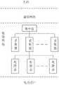
图5为本发明中低压台区抄表拓扑结构; Fig. 5 is the topological structure of meter reading in the medium and low voltage station area of the present invention;
图6为利用当前正向有功电能示值的抄表结果集合C对拓扑结构上的表计进行抄表状态标示得到的模型输入。 Fig. 6 is the model input obtained by using the meter reading result set C of the current forward active energy indication value to mark the meter reading status of the meters on the topological structure. the
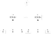
图7为以采集器为单位划分成和采集器数目一致的若干个模型子输入结构图。 Fig. 7 is a structural diagram of several model sub-inputs that are divided into several model sub-inputs that are consistent with the number of collectors. the
具体实施方式Detailed ways
本实例中,低压台区包括由主站控制的集中器、由集中器控制的各采集器,以及由各采集器分别对应控制的各表计;主站定期向集中器发送采集指令,集中器通过各采集器获取各表计的抄表数据,各采集器具有各自唯一的采集器通信地址;各表计具有各自唯一的测点号;一种低压台区抄表的故障源定位方是按如下步骤进行: In this example, the low-voltage station area includes the concentrator controlled by the master station, the collectors controlled by the concentrator, and the meters respectively controlled by the collectors; the master station periodically sends collection instructions to the concentrator, and the concentrator The meter reading data of each meter is obtained through each collector, and each collector has its own unique collector communication address; each meter has its own unique measuring point number; a fault source location method for meter reading in a low-voltage station area is based on Follow the steps below:
步骤1:获取低压台区抄表的拓扑结构: Step 1: Obtain the topology structure of meter reading in the low-voltage station area:
低压台区拓扑结构由集中器与采集器之间的对应关系以及采集器与表计之间的对应关系构成,通过简化可知只需要获取到集中器下面的所有表计集合以及表计所属的采集器即可确定低压台区的抄表拓扑结构。其中集中器下的表计集合可以从集中器中通过Q/GDW376.1-2009协议获取,表计所属的采集器信息通过主站导出后导入到现场采用的手持机中。 The topology of the low-voltage station area is composed of the corresponding relationship between the concentrator and the collector and the corresponding relationship between the collector and the meter. Through simplification, it can be known that only all the meter sets under the concentrator and the collector to which the meter belongs are obtained. The device can determine the meter reading topology of the low-voltage station area. Among them, the meter set under the concentrator can be obtained from the concentrator through the Q/GDW376.1-2009 protocol, and the information of the collector to which the meter belongs is exported by the master station and then imported into the handheld device used on site. the
如图2所示,该手持机包括主控处理模块、LCD显示屏、触摸屏、输入按键模块、I/O接口、电源及管理模块、红外数据采集模块,以及Wi-Fi通信模块,LCD显示屏、触摸屏、输入按键、I/O接口、红外数据采集模块,以及Wi-Fi通信模块均连接到主控处理模块,电源及管理模块分别连接到主控处理模块、LCD显示屏、触摸屏、输入按键模块、I/O接口、红外数据采集模块,以及Wi-Fi通信模块,用于给这些设备供电。 As shown in Figure 2, the handset includes a main control processing module, LCD display, touch screen, input button module, I/O interface, power supply and management module, infrared data acquisition module, and Wi-Fi communication module, LCD display , touch screen, input buttons, I/O interface, infrared data acquisition module, and Wi-Fi communication module are all connected to the main control processing module, and the power supply and management modules are respectively connected to the main control processing module, LCD display, touch screen, and input buttons Module, I/O interface, infrared data acquisition module, and Wi-Fi communication module are used to supply power to these devices. the
Wi-Fi模块是预置了TCP/IP协议栈的数据透传装置,通过总线连接作为主控处理模块的外部无线传输通信接口,实时与主站保持联系。 The Wi-Fi module is a data transparent transmission device with a preset TCP/IP protocol stack. It is connected to the external wireless transmission communication interface as the main control processing module through the bus, and keeps in touch with the master station in real time. the
LCD显示屏、输入按键模块和触摸屏作为主控处理模块重要的I/O端口装置,提供快捷的人机交互方式,也便于使用人员携带和操作。 LCD display screen, input button module and touch screen are important I/O port devices of the main control processing module, which provide fast human-computer interaction and are also convenient for users to carry and operate. the
集中器下面的所有表计集合获取步骤如下: The steps to obtain all meter collections under the concentrator are as follows:
步骤11、根据Q/GDW376.1-2009协议,手持机的主控处理模块获取到触摸屏或输入按键模块的输入操作指令后控制红外数据采集模块通过红外串口与集中器连接,利用通用终端地址FFFFH向集中器发送查询参数命令(AFN=0CH)中的终端脉冲配置参数(功能码F11),集 中器接收查询参数命令后将表计信息数据反馈给红外数据采集模块,红外数据采集模块接收集中器返回的表计信息数据并传递给主控处理模块进行存储; Step 11. According to the Q/GDW376.1-2009 protocol, the main control processing module of the handset obtains the input operation instructions of the touch screen or the input button module and then controls the infrared data acquisition module to connect to the concentrator through the infrared serial port, using the general terminal address FFFFH Send the terminal pulse configuration parameters (function code F11) in the query parameter command (AFN=0CH) to the concentrator, the concentrator will feed back the meter information data to the infrared data acquisition module after receiving the query parameter command, and the infrared data acquisition module will receive the centralized The meter information data returned by the meter is passed to the main control processing module for storage;
步骤12、手持机的主控处理模块解析集中器返回的表计信息数据,根据表计信息数据提取集中器中所有表计集合,具体为:根据表计信息数据获取各表计测点号与表计通信地址间的映射表作为表计集合,令表计集合为集合A;集合A中元素示例如图3所示。 Step 12. The main control processing module of the handset analyzes the meter information data returned by the concentrator, and extracts all the meter sets in the concentrator according to the meter information data. The mapping table between the communication addresses of meters is used as a set of meters, and the set of meters is set A; an example of elements in set A is shown in Figure 3. the
步骤13、获取表计所属采集器集合:具体为,利用主站提供的集中器台账信息,获得各表计测点号与表计所属采集器通信地址之间的对应关系为表计所属采集器集合; Step 13. Obtain the collection of collectors to which the meter belongs: specifically, use the ledger information of the concentrator provided by the master station to obtain the corresponding relationship between the meter measurement point number and the communication address of the collector to which the meter belongs. collection of devices;
利用主站提供的集中器台账明细查询功能,将集中器明细台账导出成csv文件,文件中内容格式如下表1所示: Use the concentrator ledger details query function provided by the main station to export the concentrator detailed ledger into a csv file. The format of the content in the file is shown in Table 1 below:
表1csv文件中内容格式 Table 1 Content format in csv file

步骤14、利用csv文件中的列和所属采集器通信地址列确定集中器下表计和采集器之间的对应关系,令表计所属采集器集合为集合B;集合B中元素示例如图4所示。 Step 14. Use the columns in the csv file and the communication address columns of the collectors to determine the corresponding relationship between the meters and collectors under the concentrator, so that the collection of collectors to which the meters belong is set B; an example of the elements in set B is shown in Figure 4 shown. the
步骤15、从集合B中获取所有的采集器通信地址形成采集器列表,列表中的所有采集器在拓扑结构中与集中器进行连接; Step 15, obtain all collector communication addresses from set B to form a collector list, and all collectors in the list are connected with the concentrator in the topology;
步骤16、针对集中器列表中的每个采集器,并在拓扑结构中将获取的表计与该采集器进行连接,最终得到采集器,利用采集器通信地址从集合A中获取到对应的表计测点号列表,由集中器、表计集合和采集器集合构成低压台区的拓扑结构;如图5所示。 Step 16. For each collector in the concentrator list, connect the obtained meters with the collector in the topology structure, and finally obtain the collector, and use the communication address of the collector to obtain the corresponding meter from set A The list of measurement point numbers, the topological structure of the low-voltage station area is composed of concentrators, meter collections and collector collections; as shown in Figure 5. the
步骤2:定义故障源识别模型: Step 2: Define the fault source identification model:
2.1)根据拓扑结构,定义故障源集合; 2.1) According to the topology, define the set of fault sources;
结合低压台区抄表的拓扑结构,本方法定义的故障源如下表2所示: Combined with the topological structure of meter reading in the low-voltage station area, the fault sources defined by this method are shown in Table 2 below:
表2定义的故障源 Fault sources defined in Table 2


2.2)根据故障源集合,定义故障源识别模型,故障源识别模型的输入数据为表计抄表结果,表计抄表结果是指集中器现场采集结果以及所有表计现场采集结果,表计抄表结果分别表征为采集成功和采集失败,用符号


表3识别模型定义 Table 3 Identification model definition


上述定义的故障源识别模型是基于集中器下表计的单次抄表状态,但针对模型中的部输入类型,模型输入只能给出可能的故障源集合,不能唯一定位故障,为此在现场可采集不同时段的多次抄表结果,利用不同时段的抄表结果给出的故障源集合进行交集以进一步缩小定位出来的故障源集合。 The fault source identification model defined above is based on the single meter reading status of the meter under the concentrator, but for all input types in the model, the model input can only give a set of possible fault sources, and cannot uniquely locate the fault. Multiple meter reading results in different time periods can be collected on site, and the fault source sets given by the meter reading results in different time periods can be used for intersection to further narrow down the located fault source set. the
本方法采用现场手持机,基于Q/GDW376.1-2009协议首先请求一类数据(AFN=0CH)中当前正向有功电能示值(F129),对请求结果进行解析获得确定的每块表计的抄表状态,记为集合C,其中抄表成功的表计当前可获取抄表时间及正向有功电能示值。 This method adopts the on-site handheld device, based on the Q/GDW376.1-2009 protocol, firstly requests the current forward active energy indication value (F129) in the first type of data (AFN=0CH), and analyzes the request result to obtain the determined value of each meter. The meter reading state of the meter is recorded as set C, where the meter reading success can currently obtain the meter reading time and positive active energy indication. the
针对需要采集其他时段抄表结果的表计,同样在现场采用手持机,基于Q/GDW376.1-2009协议首先请求二类数据(AFN=0DH)中前一日日冻结数据,对请求结果进行解析获得确定的每块表计在前一日24时的抄表状态,记为集合D。 For meters that need to collect meter reading results in other time periods, handheld devices are also used on site. Based on the Q/GDW376.1-2009 protocol, firstly request the frozen data of the previous day in the second type of data (AFN=0DH), and then perform Analyze and obtain the determined meter reading status of each meter at 24:00 of the previous day, which is recorded as set D. the
步骤3:根据拓扑结构及表计抄表结果,利用分类识别方法与故障源识别模型的输入数据实现故障源的定位。 Step 3: According to the topological structure and the results of meter reading, use the classification identification method and the input data of the fault source identification model to locate the fault source. the
基上述通过步骤1和步骤2获取到的低压台区抄表拓扑结构及表计抄表情况,本方法利用分类识别方法与上述定义的模型输入进行比对实现故障源的定位,具体步骤如下: Based on the meter reading topology and meter reading conditions of the low-voltage station area obtained through steps 1 and 2 above, this method uses the classification recognition method to compare with the model input defined above to locate the fault source. The specific steps are as follows:
步骤31:首先利用当前正向有功电能示值的抄表结果集合C对拓扑结构上的表计进行抄表状态标示,得到与定义的模型输入结构一致的模型输入,类似图6所示; Step 31: First, use the meter reading result set C of the current forward active energy indication value to mark the meter reading status of the meters on the topological structure, and obtain a model input consistent with the defined model input structure, similar to that shown in Figure 6;
步骤32:将步骤31中的模型输入与定义的模型输入①进行比对,比对时首先比对主站节点的状态,若状态一致,则匹配成功,判定故障②,诊断结束; Step 32: Compare the model input in step 31 with the defined model input ①. When comparing, first compare the status of the master station node. If the status is consistent, the matching is successful, determine the fault ②, and the diagnosis is over;
步骤33:将步骤31中的模型输入与模型输入②进行比对,比对时首先比对主站节点的状态,若状态一致,再逐个统计表记节点的状态,若表记节点为成功节点数大于0,则匹配成功,确认故障①,否则排除故障①,并后续诊断其他故障源; Step 33: Compare the model input in step 31 with the model input ②. When comparing, first compare the status of the main station node. If the status is consistent, then count the status of the registration nodes one by one. If the registration node is a successful node If the number is greater than 0, the matching is successful, confirm the fault ①, otherwise eliminate the fault ①, and then diagnose other fault sources;
步骤34:在故障源①②诊断结束继续定位集中器及表计故障,为此将步骤31中的模型输入以采集器为单位划分成多个子输入,划分方式如图7所示,形成和采集器数目一致的若干个模型子输入; Step 34: After the diagnosis of the fault source ①②, continue to locate the fault of the concentrator and the meter. For this reason, the model input in step 31 is divided into multiple sub-inputs in units of collectors. The division method is shown in Figure 7, forming and collectors Several model sub-inputs with the same number;
步骤35:针对步骤34中形成的每个模型子输入,统计输入模型中表计总数量M及抄表故障的表计数目N,若M=N,成功匹配诊断模型中的模型输入③,故障定位为故障源③④;若M>N且N>1成功匹配诊断模型中的模型输入④,故障定位为故障源⑤⑥;若M>N且N=1成功匹配诊断模型中的模型输入⑤,故障定位为故障源⑤⑥; Step 35: For each model sub-input formed in step 34, count the total number of meters M in the input model and the number N of meters with meter reading faults, if M=N, successfully match the model input ③ in the diagnosis model, the fault Locate as the fault source ③④; if M>N and N>1 successfully match the model input ④ in the diagnosis model, the fault is located as the fault source ⑤⑥; if M>N and N=1 successfully match the model input ⑤ in the diagnosis model, the fault Locate as the fault source ⑤⑥;
步骤36:在步骤35中,针对单个模型子输入,输出集合中均存在两种可能的故障源;为了进一步缩小故障源范围,本方法利用集合D对输出集合进行进一步缩减,首先利用集合D中的采集结果,结合当前的子输入的拓扑结构构建一个新的模型子输入,即对同一个采集器,构建了两例模型子输入,利用两例子输入的输出交集来对输出进行缩减,定义步骤35中匹配成功的模型输入为F,构建的新的模型子输入匹配成功的模型输入为L,本方法定义的二者交集如下表4所示。 Step 36: In step 35, for a single model sub-input, there are two possible fault sources in the output set; in order to further narrow the range of fault sources, this method uses the set D to further reduce the output set, first using the Based on the collection results of the current sub-input topology, a new model sub-input is constructed, that is, two examples of model sub-inputs are constructed for the same collector, and the output intersection of the two example inputs is used to reduce the output. Define the steps The input of the successfully matched model in 35 is F, and the input of the successfully matched model of the new model sub-input is L. The intersection of the two defined by this method is shown in Table 4 below. the
表4定义的二者交集 The intersection of the two defined in Table 4


Claims (3)
Priority Applications (1)
| Application Number | Priority Date | Filing Date | Title |
|---|---|---|---|
| CN201410041057.6ACN103760874B (en) | 2014-01-28 | 2014-01-28 | Check meter source of trouble localization method in a kind of low-voltage platform area |
Applications Claiming Priority (1)
| Application Number | Priority Date | Filing Date | Title |
|---|---|---|---|
| CN201410041057.6ACN103760874B (en) | 2014-01-28 | 2014-01-28 | Check meter source of trouble localization method in a kind of low-voltage platform area |
Publications (2)
| Publication Number | Publication Date |
|---|---|
| CN103760874Atrue CN103760874A (en) | 2014-04-30 |
| CN103760874B CN103760874B (en) | 2016-09-14 |
Family
ID=50528129
Family Applications (1)
| Application Number | Title | Priority Date | Filing Date |
|---|---|---|---|
| CN201410041057.6AActiveCN103760874B (en) | 2014-01-28 | 2014-01-28 | Check meter source of trouble localization method in a kind of low-voltage platform area |
Country Status (1)
| Country | Link |
|---|---|
| CN (1) | CN103760874B (en) |
Cited By (17)
| Publication number | Priority date | Publication date | Assignee | Title |
|---|---|---|---|---|
| CN105160853A (en)* | 2015-09-06 | 2015-12-16 | 国网山东利津县供电公司 | Electric power measurement remote meter reading failure patrolling system and method |
| CN105321331A (en)* | 2014-07-28 | 2016-02-10 | 国家电网公司 | Method, device and system for processing electricity meter information |
| CN105591826A (en)* | 2016-03-18 | 2016-05-18 | 光一科技股份有限公司 | Device and method for fault diagnosis of low-voltage power line broadband carrier communication network |
| CN105763355A (en)* | 2014-12-19 | 2016-07-13 | 深圳市国电科技通信有限公司 | Information collection and communication network management method and system |
| CN106652416A (en)* | 2017-01-10 | 2017-05-10 | 国电南瑞三能电力仪表(南京)有限公司 | Debugging output method suitable for centralized meter reading terminal |
| CN107196801A (en)* | 2017-05-27 | 2017-09-22 | 深圳市均方根科技有限公司 | A kind of platform area topological automatic identification system |
| CN108093039A (en)* | 2017-12-07 | 2018-05-29 | 积成电子股份有限公司 | It is sunk into sleep the method for ammeter based on state's net Q/GDW3761 protocol processes |
| CN108646140A (en)* | 2018-05-25 | 2018-10-12 | 广东电网有限责任公司 | A kind of method and apparatus of determining faulty equipment |
| CN109410448A (en)* | 2017-08-15 | 2019-03-01 | 广东电网有限责任公司佛山供电局 | A kind of meter register method |
| CN110009892A (en)* | 2019-05-15 | 2019-07-12 | 广东电网有限责任公司 | A kind of low-voltage collecting meter reading sand table exercise method |
| CN110470948A (en)* | 2019-08-15 | 2019-11-19 | 国网四川省电力公司电力科学研究院 | A kind of fault location system and method based on platform area circuit topology relationship |
| CN110749802A (en)* | 2019-11-01 | 2020-02-04 | 深圳供电局有限公司 | Fault positioning method and system for low-voltage distribution network |
| CN111737253A (en)* | 2020-05-25 | 2020-10-02 | 清远博依特智能科技有限公司 | Method and device for identifying interruption data of regional meter |
| CN112162174A (en)* | 2020-09-03 | 2021-01-01 | 国电南瑞科技股份有限公司 | Distribution room fault positioning method and system based on marketing and distribution integration |
| CN112557822A (en)* | 2020-12-05 | 2021-03-26 | 青岛鼎信通讯股份有限公司 | Medium-voltage distribution area topological relation positioning and identifying method |
| CN113066276A (en)* | 2021-03-18 | 2021-07-02 | 国网陕西省电力公司电力科学研究院 | Communication fault monitoring method and device for electricity consumption information acquisition system and storage medium |
| CN116723089A (en)* | 2023-05-16 | 2023-09-08 | 国网上海市电力公司 | Meter reading link fault location method based on Internet of Things |
Citations (5)
| Publication number | Priority date | Publication date | Assignee | Title |
|---|---|---|---|---|
| JPH07271759A (en)* | 1994-03-30 | 1995-10-20 | Nec Corp | Production simulation system |
| CN101989766A (en)* | 2009-08-03 | 2011-03-23 | 南京南瑞继保电气有限公司 | Method for diagnosing faults of power system on the basis of protecting action chain |
| CN102545204A (en)* | 2011-11-23 | 2012-07-04 | 广东省电力调度中心 | Automatic generation method and device of power grid fault set |
| CN103248122A (en)* | 2013-04-27 | 2013-08-14 | 国家电网公司 | Active reporting system for power failure |
| CN103490523A (en)* | 2011-12-04 | 2014-01-01 | 江苏省电力公司南京供电公司 | Intelligent power distribution network fault treatment system |
- 2014
- 2014-01-28CNCN201410041057.6Apatent/CN103760874B/enactiveActive
Patent Citations (5)
| Publication number | Priority date | Publication date | Assignee | Title |
|---|---|---|---|---|
| JPH07271759A (en)* | 1994-03-30 | 1995-10-20 | Nec Corp | Production simulation system |
| CN101989766A (en)* | 2009-08-03 | 2011-03-23 | 南京南瑞继保电气有限公司 | Method for diagnosing faults of power system on the basis of protecting action chain |
| CN102545204A (en)* | 2011-11-23 | 2012-07-04 | 广东省电力调度中心 | Automatic generation method and device of power grid fault set |
| CN103490523A (en)* | 2011-12-04 | 2014-01-01 | 江苏省电力公司南京供电公司 | Intelligent power distribution network fault treatment system |
| CN103248122A (en)* | 2013-04-27 | 2013-08-14 | 国家电网公司 | Active reporting system for power failure |
Cited By (24)
| Publication number | Priority date | Publication date | Assignee | Title |
|---|---|---|---|---|
| CN105321331A (en)* | 2014-07-28 | 2016-02-10 | 国家电网公司 | Method, device and system for processing electricity meter information |
| CN105321331B (en)* | 2014-07-28 | 2019-01-08 | 国家电网公司 | The processing method of ammeter information, apparatus and system |
| CN105763355A (en)* | 2014-12-19 | 2016-07-13 | 深圳市国电科技通信有限公司 | Information collection and communication network management method and system |
| CN105160853A (en)* | 2015-09-06 | 2015-12-16 | 国网山东利津县供电公司 | Electric power measurement remote meter reading failure patrolling system and method |
| CN105591826A (en)* | 2016-03-18 | 2016-05-18 | 光一科技股份有限公司 | Device and method for fault diagnosis of low-voltage power line broadband carrier communication network |
| CN105591826B (en)* | 2016-03-18 | 2018-12-11 | 光一科技股份有限公司 | Low-voltage power line broadband carrier communication network fault diagnosis device and method |
| CN106652416A (en)* | 2017-01-10 | 2017-05-10 | 国电南瑞三能电力仪表(南京)有限公司 | Debugging output method suitable for centralized meter reading terminal |
| CN106652416B (en)* | 2017-01-10 | 2019-08-20 | 国电南瑞三能电力仪表(南京)有限公司 | A debug output method suitable for centralized meter reading terminal |
| CN107196801A (en)* | 2017-05-27 | 2017-09-22 | 深圳市均方根科技有限公司 | A kind of platform area topological automatic identification system |
| CN109410448A (en)* | 2017-08-15 | 2019-03-01 | 广东电网有限责任公司佛山供电局 | A kind of meter register method |
| CN108093039A (en)* | 2017-12-07 | 2018-05-29 | 积成电子股份有限公司 | It is sunk into sleep the method for ammeter based on state's net Q/GDW3761 protocol processes |
| CN108093039B (en)* | 2017-12-07 | 2020-10-30 | 积成电子股份有限公司 | Method for processing sleeping electric meter based on national network Q/GDW3761 protocol |
| CN108646140A (en)* | 2018-05-25 | 2018-10-12 | 广东电网有限责任公司 | A kind of method and apparatus of determining faulty equipment |
| CN110009892A (en)* | 2019-05-15 | 2019-07-12 | 广东电网有限责任公司 | A kind of low-voltage collecting meter reading sand table exercise method |
| CN110470948A (en)* | 2019-08-15 | 2019-11-19 | 国网四川省电力公司电力科学研究院 | A kind of fault location system and method based on platform area circuit topology relationship |
| CN110749802B (en)* | 2019-11-01 | 2021-09-28 | 深圳供电局有限公司 | Fault positioning method and system for low-voltage distribution network |
| CN110749802A (en)* | 2019-11-01 | 2020-02-04 | 深圳供电局有限公司 | Fault positioning method and system for low-voltage distribution network |
| CN111737253A (en)* | 2020-05-25 | 2020-10-02 | 清远博依特智能科技有限公司 | Method and device for identifying interruption data of regional meter |
| CN111737253B (en)* | 2020-05-25 | 2023-07-14 | 清远博依特智能科技有限公司 | Regional meter break data identification method and device |
| CN112162174A (en)* | 2020-09-03 | 2021-01-01 | 国电南瑞科技股份有限公司 | Distribution room fault positioning method and system based on marketing and distribution integration |
| CN112162174B (en)* | 2020-09-03 | 2024-04-26 | 国电南瑞科技股份有限公司 | Station area fault positioning method and system based on marketing and distribution integration |
| CN112557822A (en)* | 2020-12-05 | 2021-03-26 | 青岛鼎信通讯股份有限公司 | Medium-voltage distribution area topological relation positioning and identifying method |
| CN113066276A (en)* | 2021-03-18 | 2021-07-02 | 国网陕西省电力公司电力科学研究院 | Communication fault monitoring method and device for electricity consumption information acquisition system and storage medium |
| CN116723089A (en)* | 2023-05-16 | 2023-09-08 | 国网上海市电力公司 | Meter reading link fault location method based on Internet of Things |
Also Published As
| Publication number | Publication date |
|---|---|
| CN103760874B (en) | 2016-09-14 |
Similar Documents
| Publication | Publication Date | Title |
|---|---|---|
| CN103760874B (en) | Check meter source of trouble localization method in a kind of low-voltage platform area | |
| CN106443345B (en) | A kind of fault location system and method for overhead distribution | |
| AU2011367734B2 (en) | Electric quantity collection terminal function tester | |
| CN206421561U (en) | Power information real-time data acquisition device | |
| CN203232115U (en) | A FTU field tester powered by battery | |
| CN106814286B (en) | Distribution network fault location system, method and server based on multiple fault acquisition | |
| CN108736923A (en) | A kind of low-voltage platform area line loss on-line monitoring terminal | |
| CN111257820B (en) | Three-phase intelligent electric meter wiring remote detection method | |
| CN201926727U (en) | Power quality monitor | |
| CN104901720A (en) | Monitoring device used for power user electric energy data acquire system | |
| CN110687494A (en) | Method and system for fault monitoring of remote gateway electric energy meter | |
| CN203632354U (en) | Electricity consumption information acquisition abnormity positioning system in electric network | |
| CN202957659U (en) | Line Loss Measurement and Positioning System Based on High Voltage Electric Energy Meter | |
| CN105634406A (en) | Wireless monitoring system of intelligent photovoltaic array | |
| CN111562544B (en) | Parameter consistency diagnosis method and system for digital electric energy metering system | |
| Nan et al. | Centralized automatic meter reading system based on GPRS technology | |
| CN110672983B (en) | Power failure recovery analysis and rush repair method and management system | |
| CN105785117A (en) | Metering circuit | |
| CN209329781U (en) | A distribution network operation and maintenance monitoring device | |
| CN201247311Y (en) | Electric meter tester | |
| CN103928986A (en) | Power grid dispatching wiring diagram error correction and verification system and its verification method | |
| CN203722341U (en) | Direct-current side fault data acquisition monitoring system of photovoltaic zone of photovoltaic power station | |
| CN207946476U (en) | A lightning arrester test system based on ZigBee technology | |
| CN206115680U (en) | Use electric information collection device | |
| CN204925245U (en) | Electric quantity information acquisition device |
Legal Events
| Date | Code | Title | Description |
|---|---|---|---|
| C06 | Publication | ||
| PB01 | Publication | ||
| C10 | Entry into substantive examination | ||
| SE01 | Entry into force of request for substantive examination | ||
| C14 | Grant of patent or utility model | ||
| GR01 | Patent grant |