CN103754675A - Lining paper roll clamping support and method - Google Patents
Lining paper roll clamping support and methodDownload PDFInfo
- Publication number
- CN103754675A CN103754675ACN201410053009.9ACN201410053009ACN103754675ACN 103754675 ACN103754675 ACN 103754675ACN 201410053009 ACN201410053009 ACN 201410053009ACN 103754675 ACN103754675 ACN 103754675A
- Authority
- CN
- China
- Prior art keywords
- cylinder
- mandrel
- lining paper
- internal lining
- clamping
- Prior art date
- Legal status (The legal status is an assumption and is not a legal conclusion. Google has not performed a legal analysis and makes no representation as to the accuracy of the status listed.)
- Granted
Links
- 238000000034methodMethods0.000titleclaimsabstractdescription8
- NJPPVKZQTLUDBO-UHFFFAOYSA-NnovaluronChemical compoundC1=C(Cl)C(OC(F)(F)C(OC(F)(F)F)F)=CC=C1NC(=O)NC(=O)C1=C(F)C=CC=C1FNJPPVKZQTLUDBO-UHFFFAOYSA-N0.000claims11
- 238000010276constructionMethods0.000claims2
- 238000007789sealingMethods0.000claims1
- 238000004519manufacturing processMethods0.000abstractdescription6
- 238000009434installationMethods0.000abstractdescription5
- 238000010586diagramMethods0.000description4
- 241000208125NicotianaSpecies0.000description1
- 235000002637Nicotiana tabacumNutrition0.000description1
- 238000012986modificationMethods0.000description1
- 230000004048modificationEffects0.000description1
Images


Landscapes
- Paper (AREA)
- Winding Of Webs (AREA)
Abstract
Translated fromChinese
Description
Translated fromChinese技术领域technical field
本发明涉及烟草机械领域,尤其涉及一种内衬纸卷筒装夹支架及应用内衬纸卷筒装夹支架进行内衬纸卷筒装夹的方法。The invention relates to the field of tobacco machinery, in particular to a bracket for clamping an inner-lining paper roll and a method for clamping the inner-lining paper roll by using the bracket for clamping the inner-lining paper roll.
背景技术Background technique
如图1所示,内衬纸转塔a1上有一对内衬纸卷筒装夹支架a2,分别在图中高、低两个位置上。对于内衬纸卷筒装夹支架a2来说,如图2所示,主要由卡圈a7、滑块a8、弹簧a3、座a4、夹紧块a5、芯轴a6等部分组成。内衬纸卷筒装夹支架a2的左端有一个单作用气缸(图中未示出),能够控制着内衬纸卷筒装夹支架a2对内衬纸卷筒锁紧与松开。As shown in Figure 1, there is a pair of inner lining paper reel clamping brackets a2 on the inner lining paper turret a1, which are respectively at the high and low positions in the figure. For the inner liner paper reel clamping bracket a2, as shown in Figure 2, it is mainly composed of collar a7, slider a8, spring a3, seat a4, clamping block a5, mandrel a6 and other parts. There is a single-acting cylinder (not shown in the figure) at the left end of the inner lining paper reel clamping bracket a2, which can control the inner lining paper reel clamping bracket a2 to lock and release the inner lining paper reel.
当一卷耗尽的内衬纸卷筒在内衬纸转塔a1的带动下,转至低位位置停顿后,单作用气缸开始工作,滑块a8在气缸的推动下向右侧运动,带动芯轴a6克服弹簧a3的弹簧力向右侧推进,夹紧块a5镶嵌在芯轴a6上,随着芯轴a6向右移动,夹紧块a5向下收回,松开内衬纸卷筒,此时可取下内衬纸卷筒装夹支架a2上耗尽的内衬纸卷筒。When a roll of exhausted inner lining paper is driven by the inner lining paper turret a1, turns to the low position and pauses, the single-acting cylinder starts to work, and the slider a8 moves to the right under the push of the cylinder, driving the core The shaft a6 overcomes the spring force of the spring a3 and advances to the right, and the clamping block a5 is embedded on the mandrel a6. As the mandrel a6 moves to the right, the clamping block a5 is retracted downward, and the lining paper roll is released. The exhausted inner lining paper roll on the clamping bracket a2 of the inner lining paper roll can be removed at the same time.
当内衬纸卷筒取下后,单作用气缸保持不动,紧压滑块a8,使与其连接的芯轴a6和夹紧块a5处于停顿状态,内衬纸卷筒装夹支架a2制动,便于新内衬纸卷筒装载。当新的内衬纸卷筒装在内衬纸卷筒装夹支架a2后,单作用气缸收回,在弹簧a3作用下,推动芯轴a6向左运动与芯轴a6相连的夹紧块a5向外运动,当滑块a8接触卡圈a7后,芯轴a6的运动停止,夹紧块a5锁紧卷筒。When the inner liner paper roll is removed, the single-acting cylinder remains stationary and presses the slider a8 so that the mandrel a6 and the clamping block a5 connected to it are at a standstill, and the inner liner paper roll clamping bracket a2 brakes , for easy loading of new lined paper rolls. When the new inner lining paper roll is mounted on the inner lining paper roll clamping bracket a2, the single-acting cylinder retracts, and under the action of the spring a3, pushes the mandrel a6 to move to the left and the clamping block a5 connected with the mandrel a6 When the slider a8 touches the collar a7, the movement of the mandrel a6 stops, and the clamping block a5 locks the reel.
虽然内衬纸使用部门对内衬纸卷筒的内直径有明确规定(例如75mm),但由于现今使用的内衬纸卷筒芯都为硬质纸芯,在纸芯的制造过程中,往往会存在大小差异,如果制造的纸芯直径过大,则夹紧块难以夹紧内衬纸卷筒,如果纸芯直径过小,则又会造成纸卷筒装夹不上。Although the inner diameter of the inner lining paper reel is clearly stipulated by the department using the inner lining paper (for example, 75mm), since the inner lining paper reel cores used today are all hard paper cores, in the manufacturing process of the paper cores, often There will be size differences. If the diameter of the manufactured paper core is too large, it will be difficult for the clamping block to clamp the inner lining paper roll. If the diameter of the paper core is too small, the paper roll will not be able to be clamped.
发明内容Contents of the invention
本发明的目的是提出一种内衬纸卷筒装夹支架及装夹方法,能够适应制造过程中所存在的内直径大小差异的各种内衬纸卷筒的安装夹紧。The object of the present invention is to provide a clamping bracket and clamping method for the inner lining paper roll, which can adapt to the installation and clamping of various inner lining paper rolls with different inner diameters in the manufacturing process.
为实现上述目的,本发明提供了一种内衬纸卷筒装夹支架,包括:座体、芯轴、夹紧块、滑块和卡圈,所述座体为半封闭的套筒,所述芯轴为两阶圆柱体,设置在所述座体内腔之内,并能够在所述座体的内腔中滑动,所述芯轴的外周设有多个倾斜的燕尾槽,所述夹紧块为与所述燕尾槽的倾斜角度一致的斜楔块,所述夹紧块靠近所述芯轴的轴心的一侧有与所述燕尾槽配合的燕尾形凸缘,且所述燕尾形凸缘能够在所述燕尾槽滑动,所述卡圈固定在所述座体内腔的开放一端,在所述卡圈与所述芯轴上较大直径的圆柱体段之间的滑块为弹性滑块结构,在所述芯轴与所述座体内腔的封闭一端之间还设有气缸调整弹性结构。In order to achieve the above object, the present invention provides a clamping bracket for a lined paper roll, including: a seat body, a mandrel, a clamping block, a slider and a collar, the seat body is a semi-closed sleeve, and the The mandrel is a two-stage cylinder, which is arranged in the inner cavity of the seat and can slide in the inner cavity of the seat. The outer periphery of the mandrel is provided with a plurality of inclined dovetail grooves, and the clip The tight block is an oblique wedge block consistent with the inclination angle of the dovetail groove, and the side of the clamping block close to the axis of the mandrel has a dovetail-shaped flange matched with the dovetail groove, and the dovetail The shaped flange can slide in the dovetail groove, the collar is fixed on the open end of the inner cavity of the seat, and the slider between the collar and the larger diameter cylinder section on the mandrel is The elastic slider structure is also provided with a cylinder to adjust the elastic structure between the mandrel and the closed end of the inner cavity of the seat.
进一步的,所述弹性滑块结构包括两个圆柱形滑块和设置在所述两个圆柱形滑块之间的第一弹簧,所述两个圆柱形滑块均设有通孔,并套在所述芯轴上较小直径的圆柱体段。Further, the elastic slider structure includes two cylindrical sliders and a first spring arranged between the two cylindrical sliders, the two cylindrical sliders are provided with through holes, and Smaller diameter cylindrical segments on the mandrel.
进一步的,在所述座体内腔的开放一端还设有第一气缸,所述第一气缸安装在内衬纸转塔上,所述第一气缸的活塞杆顶靠着所述芯轴上较小直径的圆柱体段。Further, a first air cylinder is also provided at the open end of the inner chamber of the seat, the first air cylinder is installed on the inner liner turret, and the piston rod of the first air cylinder leans against the mandrel relatively Small diameter cylinder segment.
进一步的,所述气缸调整弹性结构包括第二气缸、顶杆和第二弹簧,所述第二气缸安装在所述座体内腔的封闭端,并且所述第二气缸的活塞杆连接所述顶杆,所述第二弹簧设置在所述顶杆与所述芯轴上较大直径的圆柱体段之间。Further, the cylinder adjustment elastic structure includes a second cylinder, a push rod and a second spring, the second cylinder is installed at the closed end of the inner cavity of the seat, and the piston rod of the second cylinder is connected to the top rod, and the second spring is arranged between the push rod and the larger-diameter cylinder section on the mandrel.
进一步的,所述第一气缸和第二气缸均为行程可调的单作用气缸,所述第一气缸和第二气缸的无杆腔分别与换向阀的两个工作口相通,所述换向阀的进气口与气泵相通。Further, both the first cylinder and the second cylinder are single-acting cylinders with adjustable stroke, and the rodless chambers of the first cylinder and the second cylinder communicate with the two working ports of the reversing valve respectively, and the reversing valve The air inlet of the valve communicates with the air pump.
进一步的,在所述第一气缸和第二气缸的无杆腔分别与换向阀的两个工作口之间的气路上还设有单向节流阀。Further, a one-way throttle valve is also provided on the air path between the rodless chambers of the first cylinder and the second cylinder and the two working ports of the reversing valve respectively.
进一步的,所述换向阀为二位五通双电磁铁先导式换向阀。Further, the reversing valve is a two-position five-way double solenoid pilot-operated reversing valve.
为实现上述目的,本发明提供了一种应用前述内衬纸卷筒装夹支架进行内衬纸卷筒装夹的方法,包括以下步骤:In order to achieve the above object, the present invention provides a method for clamping the inner lining paper roll using the aforementioned inner lining paper roll clamping bracket, comprising the following steps:
控制换向阀的切换方向来使第一气缸伸出活塞杆,推动芯轴向座体内腔的封闭端移动,并带动第二气缸收回活塞杆;Control the switching direction of the reversing valve to make the first cylinder extend the piston rod, push the core shaft to move to the closed end of the inner cavity of the seat, and drive the second cylinder to retract the piston rod;
将内衬纸卷筒套在所述座体上,并控制所述换向阀的切换方向来使所述第二气缸伸出活塞杆,推动所述芯轴向所述座体内腔的开放端移动,并带动所述第一气缸收回活塞杆。Put the lining paper roll on the seat body, and control the switching direction of the reversing valve to make the second cylinder extend the piston rod, and push the core shaft to the open end of the seat inner cavity move, and drive the first cylinder to retract the piston rod.
基于上述技术方案,本发明利用弹性滑块结构和气缸调整弹性结构调整芯轴在座体内的位置,带动芯轴上的斜楔块从套筒中伸出或缩回,相比于现有的内衬纸卷筒装夹支架,本发明可以获得更大的调整范围,能够适应制造过程中所存在的内直径大小差异的各种内衬纸卷筒的安装夹紧。Based on the above technical solution, the present invention utilizes the elastic slider structure and the cylinder to adjust the elastic structure to adjust the position of the mandrel in the seat, and drives the wedge on the mandrel to protrude or retract from the sleeve. Compared with the existing inner The clamping bracket of the lining paper reel, the present invention can obtain a larger adjustment range, and can adapt to the installation and clamping of various inner lining paper reels with different inner diameters in the manufacturing process.
附图说明Description of drawings
此处所说明的附图用来提供对本发明的进一步理解,构成本申请的一部分,本发明的示意性实施例及其说明用于解释本发明,并不构成对本发明的不当限定。在附图中:The accompanying drawings described here are used to provide a further understanding of the present invention and constitute a part of the application. The schematic embodiments of the present invention and their descriptions are used to explain the present invention and do not constitute improper limitations to the present invention. In the attached picture:
图1为现有的内衬纸转塔的结构示意图。Fig. 1 is a structural schematic diagram of an existing paper-lined turret.
图2为现有的内衬纸卷筒装夹支架的结构示意图。Fig. 2 is a structural schematic diagram of the existing clamping bracket for the inner liner paper roll.
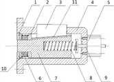
图3为本发明内衬纸卷筒装夹支架的一实施例的结构示意图。Fig. 3 is a schematic structural view of an embodiment of the clamping bracket for the inner liner paper roll of the present invention.
图4为本发明内衬纸卷筒装夹支架实施例的气路原理图。Fig. 4 is a schematic diagram of the air circuit of an embodiment of the clamping bracket for the inner liner paper roll of the present invention.
具体实施方式Detailed ways
下面通过附图和实施例,对本发明的技术方案做进一步的详细描述。The technical solution of the present invention will be described in further detail below with reference to the drawings and embodiments.
如图3所示,为本发明内衬纸卷筒装夹支架的一实施例的结构示意图。在本实施例中,内衬纸卷筒装夹支架包括:座体4、芯轴7、夹紧块3、滑块和卡圈1。座体4为半封闭的套筒,可采用法兰盘实现,能够通过底部的多个螺丝孔将座体4固定在内衬纸转塔。As shown in FIG. 3 , it is a structural schematic view of an embodiment of the lining paper roll clamping bracket of the present invention. In this embodiment, the bracket for clamping the inner liner paper roll includes: a
芯轴7为两阶圆柱体,设置在座体4的内腔之内,并能够在座体4的内腔中滑动。芯轴7的两阶圆柱体段的直径不同,并可采用塑料材质。在芯轴7的外周可设有多个倾斜的燕尾槽,夹紧块3为与燕尾槽的倾斜角度一致的斜楔块,夹紧块3靠近芯轴7的轴心的一侧有与燕尾槽配合的燕尾形凸缘11,且燕尾形凸缘11能够在燕尾槽滑动。燕尾槽除了能带动夹紧块3在径向上运动,还能够避免夹紧块3从座体4中脱出。The
座体4的内腔的开放一端(即图3中左侧一端)可以设置一卡圈槽,用来固定卡圈10,在卡圈10与芯轴7上较大直径的圆柱体段之间的滑块为弹性滑块结构,卡圈10可以对弹性滑块结构进行限位。在芯轴7与座体4的内腔的封闭一端(即图3中右侧一端)之间还设有气缸调整弹性结构。The open end of the inner cavity of the seat body 4 (i.e., the left end in Fig. 3 ) can be provided with a collar groove for fixing the
在图3所示实施例中,弹性滑块结构可以包括两个圆柱形滑块和第一弹簧6,两个圆柱形滑块分别为圆柱形滑块2和圆柱形滑块10,第一弹簧6设置在圆柱形滑块2和圆柱形滑块10之间,圆柱形滑块2和圆柱形滑块10均设有通孔,并套在芯轴7上较小直径的圆柱体段,圆柱形滑块2和圆柱形滑块10的通孔与芯轴7可以为间隙配合,而外圆柱面与座体4的内腔间隙配合,并能够在座体4的内腔滑动。为了固定第一弹簧6,可以在圆柱形滑块2的一端设置凸台,在圆柱形滑块10的另一端设置沉孔。In the embodiment shown in Figure 3, the elastic slider structure can include two cylindrical sliders and a
在另一个实施例中,在座体4的内腔的开放一端还设有第一气缸12(参见图4),第一气缸12安装在内衬纸转塔上,第一气缸12的活塞杆顶靠着芯轴7上较小直径的圆柱体段。In another embodiment, a first air cylinder 12 (see Fig. 4 ) is also provided at the open end of the inner cavity of the
在图3实施例中,气缸调整弹性结构包括第二气缸5、顶杆9和第二弹簧8,第二气缸5安装在座体4的内腔的封闭端,并且第二气缸5的活塞杆连接顶杆9,第二弹簧8设置在顶杆9与芯轴7上较大直径的圆柱体段之间。顶杆9的一端可以通过螺纹连接的方式安装在第二气缸5的活塞杆上,另一端可以设置沉孔。而芯轴7上较大直径的圆柱体段上也可以设置一沉孔,与顶杆9上的沉孔共同固定第二弹簧8。In the embodiment of Fig. 3, the cylinder adjustment elastic structure includes a
第一气缸12和第二气缸5均可采用行程可调的单作用气缸,第一气缸12用来驱动芯轴7向另一侧(即图3的右侧)移动一定的距离,进而带动夹紧块3收缩。第二气缸5用来控制芯轴7向另一侧(即图3的左侧)移动一定的距离,进而带动夹紧块3伸出。在另一个实施例中,第一气缸12和第二气缸5也可以采用双作用气缸。单作用气缸由于满足本发明气缸较高的伸出动作要求,而回程影响较小,因此优选采用单作用气缸,另外,双作用气缸的气路和控制信号更复杂。Both the
参照图4所示的气路原理图,第一气缸12和第二气缸5的无杆腔分别与换向阀14的两个工作口相通,换向阀14的进气口与气泵13相通。为了控制流入第一气缸12和第二气缸5的高压气体的流量和速度,还可以在第一气缸12和第二气缸5的无杆腔分别与换向阀14的两个工作口之间的气路上还设有单向节流阀15。换向阀14优选采用二位五通双电磁铁先导式换向阀。Referring to the schematic diagram of the air circuit shown in FIG. 4 , the rodless chambers of the
应用图4实施例所对应的内衬纸卷筒装夹支架实施例进行内衬纸卷筒装夹的方法包括以下步骤:控制换向阀的切换方向来使第一气缸伸出活塞杆,推动芯轴向座体内腔的封闭端移动,并带动第二气缸收回活塞杆,这样就将夹紧块收回到座体内;再将内衬纸卷筒套在所述座体上,并控制所述换向阀的切换方向来使所述第二气缸伸出活塞杆,推动所述芯轴向所述座体内腔的开放端移动,并带动所述第一气缸收回活塞杆,这样就利用夹紧块顶紧了内衬纸卷筒的内腔。The method for clamping a lined paper roll using the embodiment of the lining paper roll clamping bracket corresponding to the embodiment in Figure 4 includes the following steps: controlling the switching direction of the reversing valve to make the first cylinder stretch out the piston rod, pushing The core shaft moves to the closed end of the inner cavity of the seat, and drives the second cylinder to retract the piston rod, so that the clamping block is retracted into the seat; then the lining paper roll is placed on the seat, and the The switching direction of the reversing valve causes the second cylinder to extend the piston rod, pushes the core shaft to move towards the open end of the seat inner cavity, and drives the first cylinder to retract the piston rod, thus utilizing clamping The blocks tighten the inner cavity of the lined paper roll.
现有的内衬纸卷筒装夹支架的夹紧块的调整空间较小,难以适应制造过程中所存在的内直径大小差异的各种内衬纸卷筒的安装夹紧,因此往往会出现难以夹紧或者装夹不上的问题,而本发明通过弹性滑块和气缸调整弹性结构的使用,显著提高了夹紧块的调整空间,使得内衬纸卷筒装夹支架能够适应制造过程中所存在的内直径大小差异的各种内衬纸卷筒的安装夹紧。另外,气缸调整弹性结构使得夹紧块的调整更为准确可靠,实现良好的夹紧效果。The adjustment space of the clamping block of the existing lining paper roll clamping bracket is small, and it is difficult to adapt to the installation and clamping of various lining paper rolls with different inner diameters in the manufacturing process, so it often occurs It is difficult to clamp or cannot be clamped, but the present invention significantly improves the adjustment space of the clamping block through the use of the elastic slider and the cylinder to adjust the elastic structure, so that the clamping bracket of the inner liner paper roll can be adapted to the manufacturing process. The installation and clamping of various inner lining paper rolls with different inner diameters. In addition, the elastic structure of the cylinder adjustment makes the adjustment of the clamping block more accurate and reliable, and achieves a good clamping effect.
最后应当说明的是:以上实施例仅用以说明本发明的技术方案而非对其限制;尽管参照较佳实施例对本发明进行了详细的说明,所属领域的普通技术人员应当理解:依然可以对本发明的具体实施方式进行修改或者对部分技术特征进行等同替换;而不脱离本发明技术方案的精神,其均应涵盖在本发明请求保护的技术方案范围当中。Finally, it should be noted that: the above embodiments are only used to illustrate the technical solutions of the present invention and not to limit them; although the present invention has been described in detail with reference to the preferred embodiments, those of ordinary skill in the art should understand that: the present invention can still be Modifications to the specific implementation of the invention or equivalent replacement of some technical features; without departing from the spirit of the technical solution of the present invention, should be included in the scope of the technical solution claimed in the present invention.
Claims (8)
Priority Applications (1)
| Application Number | Priority Date | Filing Date | Title |
|---|---|---|---|
| CN201410053009.9ACN103754675B (en) | 2014-02-18 | 2014-02-18 | Internal lining paper reel clamping bracket and clamping method |
Applications Claiming Priority (1)
| Application Number | Priority Date | Filing Date | Title |
|---|---|---|---|
| CN201410053009.9ACN103754675B (en) | 2014-02-18 | 2014-02-18 | Internal lining paper reel clamping bracket and clamping method |
Publications (2)
| Publication Number | Publication Date |
|---|---|
| CN103754675Atrue CN103754675A (en) | 2014-04-30 |
| CN103754675B CN103754675B (en) | 2015-11-18 |
Family
ID=50522045
Family Applications (1)
| Application Number | Title | Priority Date | Filing Date |
|---|---|---|---|
| CN201410053009.9AExpired - Fee RelatedCN103754675B (en) | 2014-02-18 | 2014-02-18 | Internal lining paper reel clamping bracket and clamping method |
Country Status (1)
| Country | Link |
|---|---|
| CN (1) | CN103754675B (en) |
Cited By (6)
| Publication number | Priority date | Publication date | Assignee | Title |
|---|---|---|---|---|
| CN104876044A (en)* | 2015-04-08 | 2015-09-02 | 湖州博仁纺织品有限公司 | Fabric reel clamping mechanism of jig dyeing machine |
| CN105540408A (en)* | 2015-12-25 | 2016-05-04 | 云南昆岭薄膜工业有限公司 | Automatic clamping mechanism for hoisting compound heavy-load reel-type material |
| CN106041557A (en)* | 2016-08-03 | 2016-10-26 | 长葛市世军机械加工厂 | Machining drill bit mounting mechanism |
| CN107427974A (en)* | 2015-02-23 | 2017-12-01 | 克里斯托弗·布瓦特 | Quick Assembly System |
| CN109319557A (en)* | 2018-10-30 | 2019-02-12 | 常州永盛新材料装备股份有限公司 | A kind of mechanical gripping means of web-like broad-width material |
| CN109317944A (en)* | 2018-11-21 | 2019-02-12 | 上海交通大学 | Automatic positioning clamping device and assembly method of steel arch |
Citations (5)
| Publication number | Priority date | Publication date | Assignee | Title |
|---|---|---|---|---|
| US5299751A (en)* | 1991-11-14 | 1994-04-05 | Man Roland Druckmaschinen Ag | Clamping mandrel-engagement sensor combination, particularly for clamping printing substrate web rolls in a roll changer |
| CN201647698U (en)* | 2010-04-22 | 2010-11-24 | 杭州大华工控技术有限公司 | A slitting machine unwinding air machine chuck |
| CN201801212U (en)* | 2010-06-25 | 2011-04-20 | 湖州南浔旭锋机械有限公司 | Expansion type ground paper gripping head |
| CN202542528U (en)* | 2012-03-15 | 2012-11-21 | 东莞市钢鑫机械有限公司 | A film slitting machine rewinding air expansion shaft discharge end support device |
| CN203728271U (en)* | 2014-02-18 | 2014-07-23 | 龙岩烟草工业有限责任公司 | Clamping support for lining paper reel |
- 2014
- 2014-02-18CNCN201410053009.9Apatent/CN103754675B/ennot_activeExpired - Fee Related
Patent Citations (5)
| Publication number | Priority date | Publication date | Assignee | Title |
|---|---|---|---|---|
| US5299751A (en)* | 1991-11-14 | 1994-04-05 | Man Roland Druckmaschinen Ag | Clamping mandrel-engagement sensor combination, particularly for clamping printing substrate web rolls in a roll changer |
| CN201647698U (en)* | 2010-04-22 | 2010-11-24 | 杭州大华工控技术有限公司 | A slitting machine unwinding air machine chuck |
| CN201801212U (en)* | 2010-06-25 | 2011-04-20 | 湖州南浔旭锋机械有限公司 | Expansion type ground paper gripping head |
| CN202542528U (en)* | 2012-03-15 | 2012-11-21 | 东莞市钢鑫机械有限公司 | A film slitting machine rewinding air expansion shaft discharge end support device |
| CN203728271U (en)* | 2014-02-18 | 2014-07-23 | 龙岩烟草工业有限责任公司 | Clamping support for lining paper reel |
Cited By (8)
| Publication number | Priority date | Publication date | Assignee | Title |
|---|---|---|---|---|
| CN107427974A (en)* | 2015-02-23 | 2017-12-01 | 克里斯托弗·布瓦特 | Quick Assembly System |
| CN107427974B (en)* | 2015-02-23 | 2020-02-21 | 克里斯托弗·布瓦特 | Rapid assembly system |
| CN104876044A (en)* | 2015-04-08 | 2015-09-02 | 湖州博仁纺织品有限公司 | Fabric reel clamping mechanism of jig dyeing machine |
| CN105540408A (en)* | 2015-12-25 | 2016-05-04 | 云南昆岭薄膜工业有限公司 | Automatic clamping mechanism for hoisting compound heavy-load reel-type material |
| CN105540408B (en)* | 2015-12-25 | 2017-08-01 | 云南昆岭薄膜工业有限公司 | The automated exchanged cutter mechanism of combined type heavy duty reel type material lifting |
| CN106041557A (en)* | 2016-08-03 | 2016-10-26 | 长葛市世军机械加工厂 | Machining drill bit mounting mechanism |
| CN109319557A (en)* | 2018-10-30 | 2019-02-12 | 常州永盛新材料装备股份有限公司 | A kind of mechanical gripping means of web-like broad-width material |
| CN109317944A (en)* | 2018-11-21 | 2019-02-12 | 上海交通大学 | Automatic positioning clamping device and assembly method of steel arch |
Also Published As
| Publication number | Publication date |
|---|---|
| CN103754675B (en) | 2015-11-18 |
Similar Documents
| Publication | Publication Date | Title |
|---|---|---|
| CN103754675A (en) | Lining paper roll clamping support and method | |
| CN203728271U (en) | Clamping support for lining paper reel | |
| CN105443498B (en) | It is a kind of that there is flexible and oscillating function Integral hydraulic cylinder and its application | |
| CN106670506B (en) | Motor housing Special Purpose Machine for Processing | |
| CN108343803A (en) | Pneumatic pipe robot | |
| CN104525982A (en) | Rotating center of lathe center rest | |
| CN109026902B (en) | Multi-damping-hole-type buffer hydraulic cylinder with movable cylinder head | |
| CN105003481B (en) | Integrated variable-damping hydraulic support system | |
| CN110242641B (en) | Internal leakage inhibition hydraulic cylinder based on magnetic control shape memory alloy | |
| CN205383133U (en) | Adjustable stroke pneumatic cylinder | |
| CN205136208U (en) | Ally oneself with synchronous pneumatic cylinder more | |
| CN204934380U (en) | A kind of pipe end hydraulic cold expanding machine | |
| CN110067786B (en) | Built-in buffer device | |
| CN105605024A (en) | Hydraulic machine, in particular a hydraulic pressure exchanger | |
| CN103352958A (en) | Buffer device of hydraulic cylinder | |
| CN105856587B (en) | A kind of pendular body turns round Hydraulic Clamping Mechanism | |
| CN110873082A (en) | Reciprocating supercharger capable of stably reversing | |
| CN223398997U (en) | A hydraulic cylinder with precise pressure control | |
| CN208592491U (en) | A kind of pipe cutting apparatus | |
| CN202707680U (en) | Solid-interior single-piston short-type oil cylinder | |
| CN111637233A (en) | Pressure regulating assembly of tire pressure gun | |
| CN202707679U (en) | Solid-interior single-piston oil cylinder | |
| CN106151166A (en) | The asynchronous telescopic hydraulic cylinder of dibit | |
| CN205703744U (en) | A kind of grinding clamp | |
| CN217951198U (en) | Pneumatic rod capable of adjusting length of cylinder body |
Legal Events
| Date | Code | Title | Description |
|---|---|---|---|
| C06 | Publication | ||
| PB01 | Publication | ||
| C10 | Entry into substantive examination | ||
| SE01 | Entry into force of request for substantive examination | ||
| C14 | Grant of patent or utility model | ||
| GR01 | Patent grant | ||
| CF01 | Termination of patent right due to non-payment of annual fee | ||
| CF01 | Termination of patent right due to non-payment of annual fee | Granted publication date:20151118 |