CN103753968A - Powder paving device for three-dimensional printing system and three-dimensional printing system - Google Patents
Powder paving device for three-dimensional printing system and three-dimensional printing systemDownload PDFInfo
- Publication number
- CN103753968A CN103753968ACN201410006676.1ACN201410006676ACN103753968ACN 103753968 ACN103753968 ACN 103753968ACN 201410006676 ACN201410006676 ACN 201410006676ACN 103753968 ACN103753968 ACN 103753968A
- Authority
- CN
- China
- Prior art keywords
- guide rail
- comb
- printing system
- paving device
- powder
- Prior art date
- Legal status (The legal status is an assumption and is not a legal conclusion. Google has not performed a legal analysis and makes no representation as to the accuracy of the status listed.)
- Granted
Links
Images


Landscapes
- Road Paving Machines (AREA)
- Road Repair (AREA)
Abstract
Description
Translated fromChinese技术领域technical field
本发明涉及一种用于三维打印系统的粉末铺平装置,还涉及一种具有所述粉末铺平装置的三维打印系统。The present invention relates to a powder leveling device for a three-dimensional printing system, and also relates to a three-dimensional printing system with the powder leveling device.
背景技术Background technique
利用激光或电子束扫描固化预置的粉末层、逐层制造三维物体的三维打印技术是一种新型的制造技术。典型的三维打印工艺有激光选区熔化和电子束选区熔化,其基本的工艺步骤包括:利用粉末供应与铺平系统将粉末材料在工作平台上铺展成薄层,然后激光或电子束在粉末上移动,选择性烧结或熔化粉末材料。以上步骤不断重复直至整个三维物体制造完成。The 3D printing technology that uses laser or electron beam scanning to solidify the preset powder layer and manufacture 3D objects layer by layer is a new type of manufacturing technology. Typical 3D printing processes include laser selective melting and electron beam selective melting. The basic process steps include: using the powder supply and paving system to spread the powder material into a thin layer on the working platform, and then the laser or electron beam moves on the powder , selective sintering or melting of powdered materials. The above steps are repeated until the entire three-dimensional object is manufactured.
在制造三维物体的过程中,激光或电子束在扫描熔化粉末层时经常会出现聚球、粉末飞溅等现象,导致已成形零件的上表面不平整。粉末铺平系统需要在这种环境中正常、稳定地工作。现有的粉末铺平系统采用刮板、辊子等刚性结构,粉末铺平系统在不平整的表面移动时容易被卡住,导致制造过程被迫中断,甚至使粉末铺平系统产生不可恢复的变形甚至折断,从而恶化后续的粉末铺平效果。In the process of manufacturing three-dimensional objects, when the laser or electron beam scans the molten powder layer, there are often phenomena such as ball gathering and powder splashing, which cause the upper surface of the formed part to be uneven. Powder paving systems need to function properly and reliably in this environment. The existing powder leveling system adopts rigid structures such as scrapers and rollers, and the powder leveling system is easily stuck when moving on an uneven surface, resulting in forced interruption of the manufacturing process, and even irreversible deformation of the powder leveling system Even break off, thereby deteriorating the effect of subsequent powder paving.
发明内容Contents of the invention
本发明旨在至少解决现有技术中存在的技术问题之一。为此,本发明的一个目的在于提出一种用于三维打印系统的粉末铺平装置。The present invention aims to solve at least one of the technical problems existing in the prior art. Therefore, an object of the present invention is to provide a powder leveling device for a three-dimensional printing system.
本发明的另一个目的在于提出一种具有所述用于三维打印系统的粉末铺平装置的三维打印系统。Another object of the present invention is to provide a three-dimensional printing system with the powder leveling device for a three-dimensional printing system.
为了实现上述目的,根据本发明第一方面的实施例提出一种用于三维打印系统的粉末铺平装置,所述三维打印系统包括工作平台,所述粉末铺平装置包括:第一导轨和第二导轨,所述第一导轨和所述第二导轨间隔开地设在所述工作平台的上表面上,其中所述第一导轨的下表面的第一部分和所述第二导轨的下表面的第一部分均与所述工作平台在上下方向上间隔开;滑动件;梳子,所述梳子倾斜地设在所述滑动件上,所述梳子的下沿与所述工作平台的上表面接触;第一滚轮和第二滚轮,所述第一滚轮设在所述梳子的第一侧,所述第二滚轮设在所述梳子的第二侧;以及驱动件,所述驱动件与所述滑动件相连以便通过所述滑动件带动所述梳子在初始位置与终止位置之间移动,其中所述梳子在从所述初始位置向所述终止位置移动时,所述第一滚轮与所述第一导轨的下表面的第一部分接触,所述第二滚轮与所述第二导轨的下表面的第一部分接触。In order to achieve the above object, according to the embodiment of the first aspect of the present invention, a powder leveling device for a three-dimensional printing system is proposed, the three-dimensional printing system includes a working platform, and the powder leveling device includes: a first guide rail and a second Two guide rails, the first guide rail and the second guide rail are spaced apart on the upper surface of the working platform, wherein the first part of the lower surface of the first guide rail and the lower surface of the second guide rail The first parts are spaced apart from the working platform in the up and down direction; a slider; the comb is obliquely arranged on the slider, and the lower edge of the comb is in contact with the upper surface of the working platform; a roller and a second roller, the first roller is arranged on the first side of the comb, and the second roller is arranged on the second side of the comb; and a driving member, the driving member and the sliding member connected so as to drive the comb to move between an initial position and an end position through the sliding member, wherein when the comb moves from the initial position to the end position, the first roller and the first guide rail The first part of the lower surface of the second guide rail is in contact with the first part of the lower surface of the second guide rail.
根据本发明实施例的用于三维打印系统的粉末铺平装置通过将所述梳子倾斜地设在所述滑动件上,从而可以极大地减小所述梳子的梳齿在刮过不平整的表面时的变形应力,进而可以降低所述梳子的梳齿发生不可恢复的变形或折断的风险。而且,由于所述第一滚轮和所述第二滚轮在保持恒定的参考面上移动,因此可以使铺平得到的粉末层的厚度保持一致。因此,根据本发明实施例的用于三维打印系统的粉末铺平装置具有铺平效果好、铺平效率高、不易损坏、使用寿命长等优点。According to the powder paving device for a three-dimensional printing system according to an embodiment of the present invention, the comb can be greatly reduced when the comb teeth are scraped across an uneven surface by setting the comb obliquely on the slider. The deformation stress at the time can reduce the risk of irreversible deformation or breakage of the comb teeth of the comb. Moreover, since the first roller and the second roller move on a constant reference plane, the thickness of the powder layer obtained by paving can be kept consistent. Therefore, the powder leveling device for a three-dimensional printing system according to the embodiment of the present invention has the advantages of good leveling effect, high leveling efficiency, less damage, and long service life.
另外,根据本发明实施例的用于三维打印系统的粉末铺平装置还可以具有如下附加的技术特征:In addition, the powder paving device for a three-dimensional printing system according to an embodiment of the present invention may also have the following additional technical features:
根据本发明的一个实施例,所述梳子可枢转地设在所述滑动件上,所述粉末铺平装置还包括调节件,所述调节件可移动地设在所述滑动件上且与所述梳子接触以便调节所述梳子与所述工作平台的上表面的夹角的大小。由此可以使所述粉末铺平装置的结构更加合理,并且可以进一步提高铺平效果和铺平效率,进一步延长所述粉末铺平装置的使用寿命。According to an embodiment of the present invention, the comb is pivotably arranged on the sliding member, and the powder leveling device further includes an adjusting member, and the adjusting member is movably arranged on the sliding member and is in contact with the sliding member. The comb is in contact so as to adjust the size of the included angle between the comb and the upper surface of the working platform. Thus, the structure of the powder leveling device can be made more reasonable, the leveling effect and efficiency can be further improved, and the service life of the powder leveling device can be further extended.
根据本发明的一个实施例,所述梳子包括:本体,所述本体倾斜地设在所述滑动件上,所述本体与所述调节件接触;第一枢转轴,所述第一枢转轴设在所述本体上且可旋转地安装在所述滑动件上;第二枢转轴和第三枢转轴,所述第二枢转轴设在所述本体的第一侧,所述第三枢转轴设在所述本体的第二侧,所述第一滚轮安装在所述第二枢转轴上,所述第二滚轮安装在所述第三枢转轴上;和第一铺平部,所述第一铺平部设在所述本体上,所述第一铺平部上间隔开地设有多个第一梳齿,每个所述第一梳齿的下沿与所述工作平台的上表面接触。由此可以使所述梳子的结构更加合理。According to an embodiment of the present invention, the comb includes: a body, the body is obliquely arranged on the sliding member, and the body is in contact with the adjustment member; a first pivot shaft, the first pivot shaft is set on the body and rotatably mounted on the slider; a second pivot shaft and a third pivot shaft, the second pivot shaft is provided on the first side of the body, and the third pivot shaft is provided on the first side of the body On a second side of the body, the first roller is mounted on the second pivot shaft, the second roller is mounted on the third pivot shaft; and a first paving portion, the first The flattening part is provided on the body, and the first flattening part is provided with a plurality of first comb teeth at intervals, and the lower edge of each first comb tooth is in contact with the upper surface of the working platform . Therefore, the structure of the comb can be made more reasonable.
根据本发明的一个实施例,所述梳子还包括第二铺平部,所述第二铺平部设在所述本体上,所述第二铺平部相对所述第一铺平部远离所述初始位置,其中所述第二铺平部上间隔开地设有多个第二梳齿,每个所述第二梳齿的下沿与所述工作平台的上表面间隔预定距离。According to an embodiment of the present invention, the comb further includes a second flattening portion, the second flattening portion is provided on the body, and the second flattening portion is farther away from the first flattening portion than the first flattening portion. The initial position, wherein a plurality of second comb teeth are arranged at intervals on the second flattening part, and the lower edge of each second comb tooth is spaced a predetermined distance from the upper surface of the working platform.
通过在所述本体上设置所述第二铺平部且所述第二铺平部的第二梳齿的下沿与所述工作平台的上表面间隔预定距离,从而可以利用所述第二铺平部先对粉末进行初步铺平,即可以将粉末的推力分散到所述第一铺平部和所述第二铺平部上,由此可以减小所述梳子变形的风险。By providing the second flattening part on the body and the lower edge of the second comb teeth of the second flattening part is spaced a predetermined distance from the upper surface of the working platform, so that the second flattening part can be used The flat portion initially flattens the powder, that is, the pushing force of the powder can be distributed to the first flattening portion and the second flattening portion, thereby reducing the risk of deformation of the comb.
根据本发明的一个实施例,所述第二铺平部平行于所述第一铺平部。由此可以使所述梳子的结构更加合理。According to an embodiment of the present invention, the second flattened portion is parallel to the first flattened portion. Therefore, the structure of the comb can be made more reasonable.
根据本发明的一个实施例,相邻两个所述第二梳齿之间的间隙在所述梳子的移动方向上与所述第一梳齿相对。由于该间隙与所述第一梳齿相对,因此所述第一梳齿可以将漏出的粉末刮平,由此可以进一步提高所述粉末铺平装置的铺平效果。According to an embodiment of the present invention, the gap between two adjacent second comb teeth is opposite to the first comb teeth in the moving direction of the comb. Since the gap is opposite to the first comb teeth, the first comb teeth can scrape the leaked powder, thereby further improving the leveling effect of the powder leveling device.
根据本发明的一个实施例,所述用于三维打印系统的粉末铺平装置还包括:第一楔形块和第二楔形块,所述第一楔形块具有第一斜面,所述第二楔形块具有第二斜面;以及第一翻板和第二翻板,所述第一翻板可枢转地设在所述第一导轨的远离所述初始位置的端部且所述第一翻板的远离所述第一导轨的端面为第三斜面,所述第二翻板可枢转地设在所述第二导轨的远离所述初始位置的端部且所述第二翻板的远离所述第二导轨的端面为第四斜面,所述第三斜面支撑在所述第一斜面上,所述第四斜面支撑在所述第二斜面上。According to an embodiment of the present invention, the powder leveling device for a three-dimensional printing system further includes: a first wedge block and a second wedge block, the first wedge block has a first slope, and the second wedge block There is a second slope; and a first flap and a second flap, the first flap is pivotally arranged at the end of the first guide rail away from the initial position and the first flap is The end face far away from the first guide rail is a third slope, the second flipper is pivotally arranged at the end of the second guide rail far away from the initial position, and the end of the second flipper away from the The end surface of the second guide rail is a fourth slope, the third slope is supported on the first slope, and the fourth slope is supported on the second slope.
通过设置所述第一翻板、所述第二翻板、所述第一楔形块和所述第二楔形块,从而在所述梳子从所述终止位置移动到所述初始位置时无需与所述工作平台的上表面接触,由此可以防止所述梳子产生大变形甚至折断。By setting the first flap, the second flap, the first wedge and the second wedge, there is no need to communicate with the comb when it moves from the end position to the initial position. contact with the upper surface of the working platform, thereby preventing the comb from being greatly deformed or even broken.
根据本发明的一个实施例,所述第一翻板的上表面邻近所述第一导轨的上表面和所述第一楔形块的上表面,所述第一翻板的下表面邻近所述第一导轨的下表面,其中所述第一翻板的上表面、所述第一导轨的上表面和所述第一楔形块的上表面平齐,所述第一翻板的下表面与所述第一导轨的下表面平齐,所述第二翻板的上表面邻近所述第二导轨的上表面和所述第二楔形块的上表面,所述第二翻板的下表面邻近所述第二导轨的下表面,所述第二翻板的上表面、所述第二导轨的上表面和所述第二楔形块的上表面平齐,所述第二翻板的下表面与所述第二导轨的下表面平齐。由此可以使所述粉末铺平装置的结构更加合理,所述第一滚轮和所述第二滚轮在移动过程中更加平稳。According to an embodiment of the present invention, the upper surface of the first turning plate is adjacent to the upper surface of the first guide rail and the upper surface of the first wedge block, and the lower surface of the first turning plate is adjacent to the first The lower surface of a guide rail, wherein the upper surface of the first turnover plate, the upper surface of the first guide rail and the upper surface of the first wedge block are flush, the lower surface of the first turnover plate and the The lower surface of the first guide rail is flush, the upper surface of the second turnover plate is adjacent to the upper surface of the second guide rail and the upper surface of the second wedge block, and the lower surface of the second turnover plate is adjacent to the The lower surface of the second guide rail, the upper surface of the second turnover plate, the upper surface of the second guide rail and the upper surface of the second wedge block are flush, the lower surface of the second turnover plate and the The lower surface of the second guide rail is flush. Therefore, the structure of the powder leveling device can be made more reasonable, and the moving process of the first roller and the second roller is more stable.
根据本发明的一个实施例,所述梳子与所述工作平台的上表面的夹角为45度-85度。由此可以进一步减小所述梳子的梳齿越过障碍时的最大应力值,进一步降低所述梳子的梳齿发生不可恢复的变形或折断的风险。According to an embodiment of the present invention, the included angle between the comb and the upper surface of the working platform is 45°-85°. In this way, the maximum stress value when the teeth of the comb cross over obstacles can be further reduced, further reducing the risk of irreversible deformation or breakage of the teeth of the comb.
根据本发明的一个实施例,所述滑动件上设有螺纹孔,所述调节件螺纹配合在所述螺纹孔内,所述调节件的端部穿过所述螺纹孔且与所述梳子接触。由此可以使所述粉末铺平装置的结构更加合理,并且可以更加容易地、精确地调节所述梳子与所述工作平台的上表面的夹角α的大小。According to an embodiment of the present invention, the sliding member is provided with a threaded hole, the adjusting member is screwed into the threaded hole, and the end of the adjusting member passes through the threaded hole and contacts the comb . Therefore, the structure of the powder leveling device can be made more reasonable, and the angle α between the comb and the upper surface of the working platform can be adjusted more easily and accurately.
根据本发明第二方面的实施例提出一种三维打印系统,所述三维打印系统包括:工作平台;和粉末铺平装置,所述粉末铺平装置为根据本发明第一方面所述的用于三维打印系统的粉末铺平装置,其中所述第一导轨和所述第二导轨间隔开地设在所述工作平台的上表面上,所述第一导轨的下表面的第一部分和所述第二导轨的下表面的第一部分均与所述工作平台在上下方向上间隔开,所述梳子的下沿与所述工作平台的上表面接触。According to the embodiment of the second aspect of the present invention, a three-dimensional printing system is proposed, and the three-dimensional printing system includes: a working platform; The powder paving device of a three-dimensional printing system, wherein the first guide rail and the second guide rail are arranged on the upper surface of the working platform at intervals, and the first part of the lower surface of the first guide rail and the first guide rail The first parts of the lower surfaces of the two guide rails are spaced apart from the working platform in the up-down direction, and the lower edge of the comb is in contact with the upper surface of the working platform.
根据本发明实施例的三维打印系统通过设置根据本发明第一方面所述的用于三维打印系统的粉末铺平装置,从而具有铺平效果好、铺平效率高、不易损坏、使用寿命长等优点。The three-dimensional printing system according to the embodiment of the present invention is provided with the powder leveling device for the three-dimensional printing system according to the first aspect of the present invention, so that it has good leveling effect, high leveling efficiency, less damage, long service life, etc. advantage.
本发明的附加方面和优点将在下面的描述中部分给出,部分将从下面的描述中变得明显,或通过本发明的实践了解到。Additional aspects and advantages of the invention will be set forth in the description which follows, and in part will be obvious from the description, or may be learned by practice of the invention.
附图说明Description of drawings
本发明的上述和/或附加的方面和优点从结合下面附图对实施例的描述中将变得明显和容易理解,其中:The above and/or additional aspects and advantages of the present invention will become apparent and comprehensible from the description of the embodiments in conjunction with the following drawings, wherein:
图1是根据本发明实施例的用于三维打印系统的粉末铺平装置的结构示意图;1 is a schematic structural view of a powder paving device for a three-dimensional printing system according to an embodiment of the present invention;
图2是根据本发明实施例的用于三维打印系统的粉末铺平装置的结构示意图;2 is a schematic structural view of a powder paving device for a three-dimensional printing system according to an embodiment of the present invention;
图3是根据本发明实施例的用于三维打印系统的粉末铺平装置的结构示意图;3 is a schematic structural view of a powder paving device for a three-dimensional printing system according to an embodiment of the present invention;
图4是根据本发明实施例的用于三维打印系统的粉末铺平装置的结构示意图;4 is a schematic structural view of a powder paving device for a three-dimensional printing system according to an embodiment of the present invention;
图5是根据本发明实施例的用于三维打印系统的粉末铺平装置的梳子的局部结构示意图;5 is a schematic diagram of a partial structure of a comb used in a powder leveling device for a three-dimensional printing system according to an embodiment of the present invention;
图6是根据本发明实施例的用于三维打印系统的粉末铺平装置的梳子的局部结构示意图;6 is a schematic diagram of a partial structure of a comb used in a powder leveling device for a three-dimensional printing system according to an embodiment of the present invention;
图7是根据本发明实施例的用于三维打印系统的粉末铺平装置的梳子的结构示意图。Fig. 7 is a schematic structural view of a comb used in a powder leveling device of a three-dimensional printing system according to an embodiment of the present invention.
具体实施方式Detailed ways
下面详细描述本发明的实施例,所述实施例的示例在附图中示出,其中自始至终相同或类似的标号表示相同或类似的元件或具有相同或类似功能的元件。下面通过参考附图描述的实施例是示例性的,仅用于解释本发明,而不能理解为对本发明的限制。Embodiments of the present invention are described in detail below, examples of which are shown in the drawings, wherein the same or similar reference numerals designate the same or similar elements or elements having the same or similar functions throughout. The embodiments described below by referring to the figures are exemplary only for explaining the present invention and should not be construed as limiting the present invention.
在本发明的描述中,需要理解的是,术语“中心”、“纵向”、“横向”、“上”、“下”、“前”、“后”、“左”、“右”、“竖直”、“水平”、“顶”、“底”、“内”、“外”等指示的方位或位置关系为基于附图所示的方位或位置关系,仅是为了便于描述本发明和简化描述,而不是指示或暗示所指的装置或元件必须具有特定的方位、以特定的方位构造和操作,因此不能理解为对本发明的限制。此外,术语“第一”、“第二”仅用于描述目的,而不能理解为指示或暗示相对重要性或者隐含指明所指示的技术特征的数量。由此,限定有“第一”、“第二”的特征可以明示或者隐含地包括一个或者更多个该特征。在本发明的描述中,除非另有说明,“多个”的含义是两个或两个以上。In describing the present invention, it should be understood that the terms "center", "longitudinal", "transverse", "upper", "lower", "front", "rear", "left", "right", " The orientations or positional relationships indicated by "vertical", "horizontal", "top", "bottom", "inner" and "outer" are based on the orientations or positional relationships shown in the drawings, and are only for the convenience of describing the present invention and Simplified descriptions, rather than indicating or implying that the device or element referred to must have a particular orientation, be constructed and operate in a particular orientation, and thus should not be construed as limiting the invention. In addition, the terms "first" and "second" are used for descriptive purposes only, and cannot be interpreted as indicating or implying relative importance or implicitly specifying the quantity of indicated technical features. Thus, a feature defined as "first" and "second" may explicitly or implicitly include one or more of these features. In the description of the present invention, unless otherwise specified, "plurality" means two or more.
在本发明的描述中,需要说明的是,除非另有明确的规定和限定,术语“安装”、“相连”、“连接”应做广义理解,例如,可以是固定连接,也可以是可拆卸连接,或一体地连接;可以是机械连接,也可以是电连接;可以是直接相连,也可以通过中间媒介间接相连,可以是两个元件内部的连通。对于本领域的普通技术人员而言,可以具体情况理解上述术语在本发明中的具体含义。In the description of the present invention, it should be noted that unless otherwise specified and limited, the terms "installation", "connection" and "connection" should be understood in a broad sense, for example, it can be a fixed connection or a detachable connection. Connected, or integrally connected; it may be mechanically connected or electrically connected; it may be directly connected or indirectly connected through an intermediary, and it may be the internal communication of two components. Those of ordinary skill in the art can understand the specific meanings of the above terms in the present invention in specific situations.
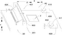
下面参考图1-图7描述根据本发明实施例的用于三维打印系统的粉末铺平装置40。如图1-图7所示,所述三维打印系统包括工作平台20,根据本发明实施例的用于三维打印系统的粉末铺平装置40包括第一导轨401、第二导轨402、滑动件403、梳子404、第一滚轮405、第二滚轮406和驱动件(图中未示出)。The following describes a
第一导轨401和第二导轨402间隔开地设在工作平台20的上表面201上,其中第一导轨401的下表面的第一部分和第二导轨402的下表面的第一部分均与工作平台20在上下方向上间隔开。梳子404倾斜地设在滑动件403上,梳子404的下沿与工作平台20的上表面201接触以便对工作平台20的上表面201上的粉末2进行铺平。换言之,梳子404相对工作平台20的上表面201倾斜设置,即梳子404与工作平台20的上表面201的夹角α大于0度且小于等于90度。也就是说,梳子404倾斜地设在滑动件403上是指:梳子404相对于工作平台20的上表面201来说是倾斜的,即梳子404相对工作平台20的上表面201倾斜地设在滑动件403上。其中,上下方向如图1-图5和图7中的箭头A所示。The
第一滚轮405设在梳子404的第一侧,第二滚轮406设在梳子404的第二侧。所述驱动件与滑动件403相连以便通过滑动件403带动梳子404在初始位置与终止位置之间移动。其中,梳子404在从所述初始位置向所述终止位置移动时,第一滚轮405与第一导轨401的下表面的所述第一部分接触,第二滚轮406与第二导轨402的下表面的所述第一部分接触。The
下面参考图1-图4描述根据本发明实施例的用于三维打印系统的粉末铺平装置40的工作过程。在图1中,粉末铺平装置40位于所述初始位置。当需要对工作平台20的上表面201上的粉末2进行铺平时,所述驱动件通过滑动件403带动梳子404从所述初始位置向所述终止位置移动(图1中的箭头示出了梳子404的移动方向)。由于梳子404的下沿与工作平台20的上表面201接触,因此可以将工作平台20的上表面201上的粉末2铺平(铺平后的粉末2如图2所示)。The following describes the working process of the
具体而言,三维打印系统可以包括成形缸,所述成形缸可以包括缸体和可上下移动地设在所述缸体内的活塞,其中所述缸体与工作平台20相连,所述缸体的上表面与工作平台20的上表面平齐。所述成形缸可以是已知的,且所述成形缸与工作平台20可以通过已知的方式相连,这与本发明的发明点无关,在此不再详细地描述。在本发明的一个具体示例中,工作平台20上可以设有沿上下方向贯通工作平台20的容纳孔202,所述成形缸的上端可以容纳在容纳孔202内。Specifically, the three-dimensional printing system may include a forming cylinder, and the forming cylinder may include a cylinder body and a piston that can move up and down in the cylinder body, wherein the cylinder body is connected with the working
由于梳子404相对工作平台20的上表面201倾斜设置,因此可以极大地减小梳子404的梳齿在刮过不平整的表面时的变形应力,从而可以降低梳子404的梳齿发生不可恢复的变形或折断的风险,由此可以使铺平过程能够顺利地进行,不会被打断。Since the
而且,在铺平粉末时,由于设在梳子404上的第一滚轮405和第二滚轮406以第一导轨401的下表面的所述第一部分和第二导轨402的下表面的所述第一部分为参考面滚动,并且粉末2不能在第一导轨401的下表面的所述第一部分和第二导轨402的下表面的所述第一部分上积累,因此可以保证该参考面的恒定。而且,当梳子404刮过障碍时,第一导轨401和第二导轨402向梳子404产生向下的压紧力,从而保证梳子404可以完全依靠梳齿的弹性变形越过障碍。由于该参考面可以保持恒定,因此梳子404不会被整体抬升,从而不会导致没有障碍的地方的粉末层变厚,即可以使铺平得到的粉末层的厚度保持一致。Moreover, when the powder is spread, the first part of the lower surface of the
根据本发明实施例的用于三维打印系统的粉末铺平装置40通过将梳子404倾斜地设在滑动件403上,从而可以极大地减小梳子404的梳齿在刮过不平整的表面时的变形应力,进而可以降低梳子404的梳齿发生不可恢复的变形或折断的风险。而且,由于第一滚轮405和第二滚轮406在保持恒定的参考面上移动,因此可以使铺平得到的粉末层的厚度保持一致。因此,根据本发明实施例的用于三维打印系统的粉末铺平装置40具有铺平效果好、铺平效率高、不易损坏、使用寿命长等优点。According to the
理论计算表明,梳子404与工作平台20的上表面201的夹角α越小,梳子404的梳齿在越过同样高度的障碍时的最大应力值越小。例如,当夹角α为65度时,梳子404的梳齿越过0.2毫米高的障碍时,梳子404的梳齿所受的最大应力值为梳子404垂直设在工作平台20的上表面201(即梳子404垂直于工作平台20的上表面201)时梳齿所受的最大应力值的13.4%,梳子404的梳齿越过0.6毫米高的障碍时,梳子404的梳齿所受的最大应力值为梳子404垂直设在工作平台20的上表面201时梳齿所受的最大应力值的31.8%。Theoretical calculations show that the smaller the angle α between the
有利地,梳子404与工作平台20的上表面201的夹角α可以是45度-85度。由此可以进一步减小梳子404的梳齿越过障碍时的最大应力值,进一步降低梳子404的梳齿发生不可恢复的变形或折断的风险。Advantageously, the angle α between the
进一步有利地,梳子404与工作平台20的上表面201的夹角α可以是65度。由此可以进一步减小梳子404的梳齿越过障碍时的最大应力值,进一步降低梳子404的梳齿发生不可恢复的变形或折断的风险。Further advantageously, the included angle α between the
如图1-图4所示,在本发明的一些实施例中,梳子404可以可枢转地设在滑动件403上,粉末铺平装置40还可以包括调节件407,调节件407可以可移动地设在滑动件403上,且调节件407可以与梳子404接触以便调节梳子404与工作平台20的上表面201的夹角α的大小。由此可以使粉末铺平装置40的结构更加合理,并且可以进一步提高铺平效果和铺平效率,进一步延长粉末铺平装置40的使用寿命。As shown in FIGS. 1-4 , in some embodiments of the present invention, the
有利地,滑动件403上可以设有螺纹孔,调节件407可以螺纹配合在螺纹孔内,调节件407的端部可以穿过螺纹孔且与梳子404接触。由此可以使粉末铺平装置40的结构更加合理,并且可以更加容易地、精确地调节梳子404与工作平台20的上表面201的夹角α的大小。Advantageously, the sliding
下面以梳子404在左右方向上移动为例,描述利用调节件407调节梳子404与工作平台20的上表面201的夹角α的大小的过程,其中左右方向如图1-图4中的箭头B所示。梳子404的主体位于滑动件403的左侧,且梳子404位于调节件407的左侧,调节件407的左端可以穿过螺纹孔且调节件407的左端可以与梳子404接触。当需要增大梳子404与工作平台20的上表面201的夹角α时,可以旋转调节件407以便使调节件407向右移动。当需要减小梳子404与工作平台20的上表面201的夹角α时,可以旋转调节件407以便使调节件407向左移动。Taking the
如图1-图4所示,在本发明的一个实施例中,用于三维打印系统的粉末铺平装置40还包括第一楔形块408、第二楔形块409、第一翻板410和第二翻板411。第一楔形块408可以具有第一斜面4081,第二楔形块409可以具有第二斜面4091。第一翻板410可以可枢转地设在第一导轨401的远离所述初始位置的端部(例如第一导轨401的右端)且第一翻板410的远离第一导轨401的端面(例如第一翻板410的右端面)可以是第三斜面4101。As shown in FIGS. 1-4 , in one embodiment of the present invention, the
第二翻板411可以可枢转地设在第二导轨402的远离所述初始位置的端部(例如第二导轨402的右端)且第二翻板411的远离第二导轨402的端面(例如第二翻板411的右端面)可以是第四斜面4111。其中,第三斜面4101可以支撑在第一斜面4081上,第四斜面4111可以支撑在第二斜面4091上。在对粉末2进行铺平时,梳子404从所述初始位置向第一导轨401的远离所述初始位置的端部和第二导轨402的远离所述初始位置的端部移动。The
梳子404铺平粉末2后继续向所述终止位置移动,当第一滚轮405移动至第一斜面4081且第二滚轮406移动至第二斜面4091后,第一滚轮405沿第一斜面4081且第二滚轮406沿第二斜面4091向上移动,并且第一滚轮405可以顶开第一翻板410且第二滚轮406可以顶开第二翻板411(如图2所示)。如图3所示,当第一滚轮405移动到第一楔形块408的上表面4082且第二滚轮406移动到第二楔形块409的上表面4092时,梳子404位于所述终止位置,第一翻板410和第二翻板411恢复原状。此时,梳子404被向上抬升了一段距离,且梳子404不再与工作平台20的上表面201接触。After the
然后,所述驱动件可以带动梳子404从所述终止位置向所述初始位置移动,第一滚轮405依次经过第一楔形块408的上表面4082、第一翻板410的上表面4102和第一导轨401的上表面4013,第二滚轮406依次经过第二楔形块409的上表面4092、第二翻板411的上表面4112和第二导轨402的上表面4021。最后,第一滚轮405从第一导轨401的上表面4013上滚落且第二滚轮406从第二导轨402的上表面4021上滚轮,此时梳子404回到所述初始位置。Then, the driving member can drive the
如果梳子404在工作平台20的上表面201上进行回程移动,即梳子404在工作平台20的上表面201上从所述终止位置移动到所述初始位置,则梳子404容易顶住不平整的表面,导致梳子404产生大变形甚至折断。因此,通过设置第一翻板410、第二翻板411、第一楔形块408和第二楔形块409,从而在梳子404从所述终止位置移动到所述初始位置时无需与工作平台20的上表面201接触,由此可以防止梳子404产生大变形甚至折断。If the
有利地,第一斜面4081可以平行于第三斜面4101(第一翻板410未被顶起时),第二斜面4091可以平行于第四斜面4111(第二翻板411未被顶起时)。Advantageously, the
如图1-图4所示,第一翻板410的上表面4102可以邻近第一导轨401的上表面4013和第一楔形块408的上表面4082,第一翻板410的下表面可以邻近第一导轨401的下表面。第一翻板410的上表面4102、第一导轨401的上表面4013和第一楔形块408的上表面4082可以平齐,第一翻板410的下表面可以与第一导轨401的下表面平齐。As shown in Figures 1-4, the
第二翻板411的上表面4112可以邻近第二导轨402的上表面4021和第二楔形块409的上表面4092,第二翻板411的下表面可以邻近第二导轨402的下表面。第二翻板411的上表面4112、第二导轨402的上表面4021和第二楔形块409的上表面4092可以平齐,第二翻板411的下表面可以与第二导轨402的下表面平齐。由此可以使粉末铺平装置40的结构更加合理,第一滚轮405和第二滚轮406在移动过程中更加平稳。The
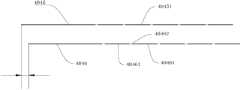
如图1-图4和图7所示,在本发明的一些示例中,梳子404可以包括本体4041、第一枢转轴4042、第二枢转轴4043、第三枢转轴4044和第一铺平部4045。本体4041可以倾斜地设在滑动件403上,本体4041可以与调节件407接触。第一枢转轴4042可以设在本体4041上,且第一枢转轴4042可以可旋转地安装在滑动件403上。第二枢转轴4043可以设在本体4041的第一侧,第三枢转轴4044可以设在本体4041的第二侧,本体4041的第一侧与本体4041的第二侧可以相对。第一滚轮405可以安装在第二枢转轴4043上,第二滚轮406可以安装在第三枢转轴4044上。第一铺平部4045可以设在本体4041上,第一铺平部4045上可以间隔开地设有多个第一梳齿40451,每个第一梳齿40451的下沿可以与工作平台20的上表面201接触。每个第一梳齿40451相对工作平台20的上表面201倾斜地设置。由此可以使梳子404的结构更加合理。As shown in FIGS. 1-4 and 7 , in some examples of the present invention, the
第一枢转轴4042可以是两个,一个第一枢转轴4042可以设在本体4041的第一侧上,另一个第一枢转轴4042可以设在本体4041的第二侧上。There can be two
有利地,本体4041可以是平板状,第一铺平部4045可以是平板状,且第一铺平部4045可以平行于本体4041。本体4041和第一铺平部4045都可以相对工作平台20的上表面201倾斜地设置。Advantageously, the
在本发明的一个示例中,如图5和图6所示,梳子404还可以包括第二铺平部4046,第二铺平部4046可以设在本体4041上,第二铺平部4046可以相对第一铺平部4045远离所述初始位置。具体地,第二铺平部4046可以位于第一铺平部4045的右侧。其中,第二铺平部4046上可以间隔开地设有多个第二梳齿40461,每个第二梳齿40461的下沿可以与工作平台20的上表面201间隔预定距离。In an example of the present invention, as shown in FIGS. 5 and 6 , the
通过在本体4041上设置第二铺平部4046且第二铺平部4046的第二梳齿40461的下沿与工作平台20的上表面201间隔预定距离,从而可以利用第二铺平部4046先对粉末2进行初步铺平,即可以将粉末2的推力分散到第一铺平部4045和第二铺平部4046上,由此可以减小梳子404变形的风险。具体而沿,每个第二梳齿40461的下沿与工作平台20的上表面201之间的距离为Δh(如图5所示)。By setting the
有利地,第二铺平部4046可以是平板状,且第二铺平部4046可以平行于第一铺平部4045和本体4041。由此可以使梳子404的结构更加合理。本体4041、第一铺平部4045和第二铺平部4046都可以相对工作平台20的上表面201倾斜地设置。每个第二梳齿40461的下沿与工作平台20的上表面201之间的距离可以大于0且小于等于1毫米。优选地,每个第二梳齿40461的下沿与工作平台20的上表面201之间的距离可以是0.2毫米。Advantageously, the second flattened
如图6所示,第一铺平部4045和第二铺平部4046可以采用弹性较好的材料制成,并利用线切割加工出等间距的槽,以便形成一列第一梳齿40451和一列第二梳齿40461。每个第一梳齿40451的宽度可以是1毫米,每个第二梳齿40461的宽度可以是1毫米。As shown in Figure 6, the first flattened
第一铺平部4045和第二铺平部4046的厚度可以根据材料而定,一般在0.1毫米-1毫米。有利地,第一铺平部4045和第二铺平部4046都可以由弹簧钢支撑,第一铺平部4045的厚度和第二铺平部4046的厚度都可以是0.4毫米。The thickness of the first flattened
如图5和图6所示,有利地,第二铺平部4046可以平行于第一铺平部4045。由此可以使梳子404的结构更加合理。As shown in FIGS. 5 and 6 , advantageously, the second flattened
在本发明的一个具体示例中,如图6所示,相邻两个第二梳齿40461之间的间隙40462在梳子404的移动方向(例如左右方向)上可以与第一梳齿40451相对。换言之,第一铺平部4045与第二铺平部4046可以错开设置。当第二铺平部4046刮过粉末2时,会有粉末2从相邻两个第二梳齿40461之间的间隙中漏出。由于该间隙与第一梳齿40451相对,因此第一梳齿40451可以将漏出的粉末2刮平,由此可以进一步提高粉末铺平装置40的铺平效果。In a specific example of the present invention, as shown in FIG. 6 , the
如图1-图4所示,第一导轨401和第二导轨402中的每一个可以包括导轨部4011和支撑部4012。支撑部4012可以设在工作平台20的上表面201上,导轨部4011可以设在支撑部4012上,且导轨部4011可以位于工作平台20的上方。也就是说,导轨部4011的下表面与工作平台20在上下方向上间隔开。As shown in FIGS. 1-4 , each of the
本发明还提供了一种三维打印系统。根据本发明实施例的三维打印系统包括工作平台20和粉末铺平装置。所述粉末铺平装置为根据上述实施例的粉末铺平装置40。其中,第一导轨401和第二导轨402间隔开地设在工作平台20的上表面201上,第一导轨401的下表面的第一部分和第二导轨402的下表面的第一部分均与工作平台20在上下方向上间隔开,梳子404的下沿与工作平台20的上表面201接触。The invention also provides a three-dimensional printing system. The three-dimensional printing system according to the embodiment of the present invention includes a working
根据本发明实施例的三维打印系统通过设置根据上述实施例的用于三维打印系统的粉末铺平装置40,从而具有铺平效果好、铺平效率高、不易损坏、使用寿命长等优点。The 3D printing system according to the embodiment of the present invention has the advantages of good leveling effect, high leveling efficiency, less damage and long service life by setting the
在本说明书的描述中,参考术语“一个实施例”、“一些实施例”、“示意性实施例”、“示例”、“具体示例”、或“一些示例”等的描述意指结合该实施例或示例描述的具体特征、结构、材料或者特点包含于本发明的至少一个实施例或示例中。在本说明书中,对上述术语的示意性表述不一定指的是相同的实施例或示例。而且,描述的具体特征、结构、材料或者特点可以在任何的一个或多个实施例或示例中以合适的方式结合。In the description of this specification, references to the terms "one embodiment," "some embodiments," "exemplary embodiments," "example," "specific examples," or "some examples" are intended to mean that the implementation A specific feature, structure, material, or characteristic described by an embodiment or example is included in at least one embodiment or example of the present invention. In this specification, schematic representations of the above terms do not necessarily refer to the same embodiment or example. Furthermore, the specific features, structures, materials or characteristics described may be combined in any suitable manner in any one or more embodiments or examples.
尽管已经示出和描述了本发明的实施例,本领域的普通技术人员可以理解:在不脱离本发明的原理和宗旨的情况下可以对这些实施例进行多种变化、修改、替换和变型,本发明的范围由权利要求及其等同物限定。Although the embodiments of the present invention have been shown and described, those skilled in the art can understand that various changes, modifications, substitutions and modifications can be made to these embodiments without departing from the principle and spirit of the present invention. The scope of the invention is defined by the claims and their equivalents.
Claims (11)
Priority Applications (1)
| Application Number | Priority Date | Filing Date | Title |
|---|---|---|---|
| CN201410006676.1ACN103753968B (en) | 2014-01-07 | 2014-01-07 | For powder paving device and the 3 D-printing system of 3 D-printing system |
Applications Claiming Priority (1)
| Application Number | Priority Date | Filing Date | Title |
|---|---|---|---|
| CN201410006676.1ACN103753968B (en) | 2014-01-07 | 2014-01-07 | For powder paving device and the 3 D-printing system of 3 D-printing system |
Publications (2)
| Publication Number | Publication Date |
|---|---|
| CN103753968Atrue CN103753968A (en) | 2014-04-30 |
| CN103753968B CN103753968B (en) | 2015-10-28 |
Family
ID=50521356
Family Applications (1)
| Application Number | Title | Priority Date | Filing Date |
|---|---|---|---|
| CN201410006676.1AActiveCN103753968B (en) | 2014-01-07 | 2014-01-07 | For powder paving device and the 3 D-printing system of 3 D-printing system |
Country Status (1)
| Country | Link |
|---|---|
| CN (1) | CN103753968B (en) |
Cited By (4)
| Publication number | Priority date | Publication date | Assignee | Title |
|---|---|---|---|---|
| CN104828589A (en)* | 2015-05-06 | 2015-08-12 | 苏州秉创科技有限公司 | Double-roller feeding mechanism |
| CN107150121A (en)* | 2016-03-04 | 2017-09-12 | 空中客车德国运营有限责任公司 | Increasing material manufacturing system and the method for increasing material manufacturing for component |
| CN109153179A (en)* | 2016-08-31 | 2019-01-04 | 惠普发展公司,有限责任合伙企业 | 3 D-printing |
| CN112659315A (en)* | 2020-12-17 | 2021-04-16 | 扬州大学 | Laying device and process for forming photocuring ceramic |
Citations (15)
| Publication number | Priority date | Publication date | Assignee | Title |
|---|---|---|---|---|
| JPS61110701A (en)* | 1984-11-01 | 1986-05-29 | Kawasaki Steel Corp | Finish heat treatment of iron and steel powder |
| CN201231215Y (en)* | 2008-07-23 | 2009-05-06 | 合肥波林新材料有限公司 | Powder layering device for bimetal composite material of single-block operation |
| JP2009256958A (en)* | 2008-04-16 | 2009-11-05 | Nippo Corp | Powder spreader |
| CN101658938A (en)* | 2009-09-09 | 2010-03-03 | 江苏希西维轴承有限公司 | Power laying machine for laying powder on steel belt |
| CN101704108A (en)* | 2009-11-11 | 2010-05-12 | 上海工程技术大学 | Roll-type automatic power spreading device and method |
| CN201693176U (en)* | 2010-06-13 | 2011-01-05 | 华南理工大学 | Rapid prototyping flexible pre-set metal powder spreading device |
| CN102078963A (en)* | 2010-12-21 | 2011-06-01 | 湖南美纳科技有限公司 | SLS (selective laser sintering) double-roller powder spreading device |
| CN102442546A (en)* | 2011-09-09 | 2012-05-09 | 西北有色金属研究院 | Powder spreading device for rapid forming equipment |
| CN202379483U (en)* | 2011-11-16 | 2012-08-15 | 华中科技大学 | Movable arm type powder paving device for powder bed |
| CN202448496U (en)* | 2012-03-02 | 2012-09-26 | 华中科技大学 | Piezoelectric three-dimensional printing shaping system |
| CN202539568U (en)* | 2011-12-08 | 2012-11-21 | 北京工业大学 | Powder spreading device for rapid forming |
| CN202779801U (en)* | 2012-09-29 | 2013-03-13 | 福建核威复合材料科技有限公司 | Movable type full-automatic powder spreading device |
| CN103143707A (en)* | 2013-03-23 | 2013-06-12 | 钱波 | Novel metal powder melting and quick forming machine |
| CN103192080A (en)* | 2013-04-27 | 2013-07-10 | 余振新 | Selective laser sintering forming method |
| CN203265633U (en)* | 2013-05-27 | 2013-11-06 | 哈尔滨德昱健行科技有限公司 | Novel powder spreading structure of metal powder melting and fast-forming machine |
- 2014
- 2014-01-07CNCN201410006676.1Apatent/CN103753968B/enactiveActive
Patent Citations (15)
| Publication number | Priority date | Publication date | Assignee | Title |
|---|---|---|---|---|
| JPS61110701A (en)* | 1984-11-01 | 1986-05-29 | Kawasaki Steel Corp | Finish heat treatment of iron and steel powder |
| JP2009256958A (en)* | 2008-04-16 | 2009-11-05 | Nippo Corp | Powder spreader |
| CN201231215Y (en)* | 2008-07-23 | 2009-05-06 | 合肥波林新材料有限公司 | Powder layering device for bimetal composite material of single-block operation |
| CN101658938A (en)* | 2009-09-09 | 2010-03-03 | 江苏希西维轴承有限公司 | Power laying machine for laying powder on steel belt |
| CN101704108A (en)* | 2009-11-11 | 2010-05-12 | 上海工程技术大学 | Roll-type automatic power spreading device and method |
| CN201693176U (en)* | 2010-06-13 | 2011-01-05 | 华南理工大学 | Rapid prototyping flexible pre-set metal powder spreading device |
| CN102078963A (en)* | 2010-12-21 | 2011-06-01 | 湖南美纳科技有限公司 | SLS (selective laser sintering) double-roller powder spreading device |
| CN102442546A (en)* | 2011-09-09 | 2012-05-09 | 西北有色金属研究院 | Powder spreading device for rapid forming equipment |
| CN202379483U (en)* | 2011-11-16 | 2012-08-15 | 华中科技大学 | Movable arm type powder paving device for powder bed |
| CN202539568U (en)* | 2011-12-08 | 2012-11-21 | 北京工业大学 | Powder spreading device for rapid forming |
| CN202448496U (en)* | 2012-03-02 | 2012-09-26 | 华中科技大学 | Piezoelectric three-dimensional printing shaping system |
| CN202779801U (en)* | 2012-09-29 | 2013-03-13 | 福建核威复合材料科技有限公司 | Movable type full-automatic powder spreading device |
| CN103143707A (en)* | 2013-03-23 | 2013-06-12 | 钱波 | Novel metal powder melting and quick forming machine |
| CN103192080A (en)* | 2013-04-27 | 2013-07-10 | 余振新 | Selective laser sintering forming method |
| CN203265633U (en)* | 2013-05-27 | 2013-11-06 | 哈尔滨德昱健行科技有限公司 | Novel powder spreading structure of metal powder melting and fast-forming machine |
Cited By (7)
| Publication number | Priority date | Publication date | Assignee | Title |
|---|---|---|---|---|
| CN104828589A (en)* | 2015-05-06 | 2015-08-12 | 苏州秉创科技有限公司 | Double-roller feeding mechanism |
| CN107150121A (en)* | 2016-03-04 | 2017-09-12 | 空中客车德国运营有限责任公司 | Increasing material manufacturing system and the method for increasing material manufacturing for component |
| US10722944B2 (en) | 2016-03-04 | 2020-07-28 | Airbus Operations Gmbh | Additive manufacturing system and method for additive manufacturing of components |
| CN109153179A (en)* | 2016-08-31 | 2019-01-04 | 惠普发展公司,有限责任合伙企业 | 3 D-printing |
| CN109153179B (en)* | 2016-08-31 | 2021-08-10 | 惠普发展公司,有限责任合伙企业 | Three-dimensional printing |
| CN112659315A (en)* | 2020-12-17 | 2021-04-16 | 扬州大学 | Laying device and process for forming photocuring ceramic |
| CN112659315B (en)* | 2020-12-17 | 2022-07-19 | 扬州大学 | Laying device and process for forming photocuring ceramic |
Also Published As
| Publication number | Publication date |
|---|---|
| CN103753968B (en) | 2015-10-28 |
Similar Documents
| Publication | Publication Date | Title |
|---|---|---|
| CN103753968B (en) | For powder paving device and the 3 D-printing system of 3 D-printing system | |
| CN103737932B (en) | For powder mixing device and the 3 D-printing system of 3 D-printing system | |
| TWI473772B (en) | Groove processing tool for thin film solar cell and groove processing device for thin film solar cell | |
| US9828188B2 (en) | Belt stripper having module inclination | |
| CN108790153B (en) | Powder spreading device and printer | |
| TW201130197A (en) | Group-III nitride semiconductor laser device, method of fabricating group-III nitride semiconductor laser device, and method of estimating damage from formation of scribe groove | |
| CN205464327U (en) | Shop's powder device of selectivity laser sintering equipment | |
| US11597147B2 (en) | Ultrasonic spreading blades with kickers | |
| CN106475562A (en) | A kind of double scraper power spreading device of increasing material manufacturing attritive powder and its method | |
| CN206474675U (en) | A kind of double scraper power spreading devices of increasing material manufacturing attritive powder | |
| CN103252804B (en) | The groove processing instrument of substrate and groove processing apparatus | |
| CN203612511U (en) | Material conveying device for paving machine | |
| CN204449007U (en) | A kind of drift fast replacing device | |
| EP3007872B1 (en) | Splitting apparatus for splitting a masonry block and method of processing such a block | |
| CN104028659B (en) | A kind of side direction feeding pressure mechanism and press tool | |
| CN115126026A (en) | Slot milling machine Milling device and slot milling machine | |
| CN104078529B (en) | Groove processing tool and groove processing apparatus using the same | |
| CN104313953A (en) | Ballast leveling device | |
| JP6287165B2 (en) | Cutting device | |
| CN103658701A (en) | Adjustable boring tool for finishing work | |
| CN203565893U (en) | Adjustable boring cutter used for finish machining | |
| CN102442765B (en) | Scribing method of glass panel | |
| CN115142326A (en) | A road construction pavement slotting machine with an anti-offset structure | |
| CN102151760B (en) | Multi-station continuous mould drawing translational station mechanism | |
| CN210066435U (en) | Plastic track mixed type and all-plastic paver |
Legal Events
| Date | Code | Title | Description |
|---|---|---|---|
| C06 | Publication | ||
| PB01 | Publication | ||
| C10 | Entry into substantive examination | ||
| SE01 | Entry into force of request for substantive examination | ||
| C14 | Grant of patent or utility model | ||
| GR01 | Patent grant |