CN103746471A - Side-standing magnetic filed motor and cooling fan using side-standing magnetic filed motor - Google Patents
Side-standing magnetic filed motor and cooling fan using side-standing magnetic filed motorDownload PDFInfo
- Publication number
- CN103746471A CN103746471ACN201310753140.1ACN201310753140ACN103746471ACN 103746471 ACN103746471 ACN 103746471ACN 201310753140 ACN201310753140 ACN 201310753140ACN 103746471 ACN103746471 ACN 103746471A
- Authority
- CN
- China
- Prior art keywords
- magnetic field
- edge
- field electric
- heat conduction
- heat
- Prior art date
- Legal status (The legal status is an assumption and is not a legal conclusion. Google has not performed a legal analysis and makes no representation as to the accuracy of the status listed.)
- Granted
Links
Images


Classifications
- H—ELECTRICITY
- H02—GENERATION; CONVERSION OR DISTRIBUTION OF ELECTRIC POWER
- H02K—DYNAMO-ELECTRIC MACHINES
- H02K1/00—Details of the magnetic circuit
- H02K1/06—Details of the magnetic circuit characterised by the shape, form or construction
- H02K1/12—Stationary parts of the magnetic circuit
- F—MECHANICAL ENGINEERING; LIGHTING; HEATING; WEAPONS; BLASTING
- F04—POSITIVE - DISPLACEMENT MACHINES FOR LIQUIDS; PUMPS FOR LIQUIDS OR ELASTIC FLUIDS
- F04D—NON-POSITIVE-DISPLACEMENT PUMPS
- F04D25/00—Pumping installations or systems
- F04D25/02—Units comprising pumps and their driving means
- F04D25/06—Units comprising pumps and their driving means the pump being electrically driven
- F04D25/0606—Units comprising pumps and their driving means the pump being electrically driven the electric motor being specially adapted for integration in the pump
- F—MECHANICAL ENGINEERING; LIGHTING; HEATING; WEAPONS; BLASTING
- F04—POSITIVE - DISPLACEMENT MACHINES FOR LIQUIDS; PUMPS FOR LIQUIDS OR ELASTIC FLUIDS
- F04D—NON-POSITIVE-DISPLACEMENT PUMPS
- F04D19/00—Axial-flow pumps
- F04D19/002—Axial flow fans
- F—MECHANICAL ENGINEERING; LIGHTING; HEATING; WEAPONS; BLASTING
- F04—POSITIVE - DISPLACEMENT MACHINES FOR LIQUIDS; PUMPS FOR LIQUIDS OR ELASTIC FLUIDS
- F04D—NON-POSITIVE-DISPLACEMENT PUMPS
- F04D25/00—Pumping installations or systems
- F04D25/02—Units comprising pumps and their driving means
- F04D25/06—Units comprising pumps and their driving means the pump being electrically driven
- F04D25/0606—Units comprising pumps and their driving means the pump being electrically driven the electric motor being specially adapted for integration in the pump
- F04D25/0613—Units comprising pumps and their driving means the pump being electrically driven the electric motor being specially adapted for integration in the pump the electric motor being of the inside-out type, i.e. the rotor is arranged radially outside a central stator
- F—MECHANICAL ENGINEERING; LIGHTING; HEATING; WEAPONS; BLASTING
- F04—POSITIVE - DISPLACEMENT MACHINES FOR LIQUIDS; PUMPS FOR LIQUIDS OR ELASTIC FLUIDS
- F04D—NON-POSITIVE-DISPLACEMENT PUMPS
- F04D25/00—Pumping installations or systems
- F04D25/02—Units comprising pumps and their driving means
- F04D25/08—Units comprising pumps and their driving means the working fluid being air, e.g. for ventilation
- F04D25/082—Units comprising pumps and their driving means the working fluid being air, e.g. for ventilation the unit having provision for cooling the motor
- F—MECHANICAL ENGINEERING; LIGHTING; HEATING; WEAPONS; BLASTING
- F04—POSITIVE - DISPLACEMENT MACHINES FOR LIQUIDS; PUMPS FOR LIQUIDS OR ELASTIC FLUIDS
- F04D—NON-POSITIVE-DISPLACEMENT PUMPS
- F04D29/00—Details, component parts, or accessories
- F04D29/26—Rotors specially for elastic fluids
- F04D29/32—Rotors specially for elastic fluids for axial flow pumps
- F04D29/325—Rotors specially for elastic fluids for axial flow pumps for axial flow fans
- F—MECHANICAL ENGINEERING; LIGHTING; HEATING; WEAPONS; BLASTING
- F04—POSITIVE - DISPLACEMENT MACHINES FOR LIQUIDS; PUMPS FOR LIQUIDS OR ELASTIC FLUIDS
- F04D—NON-POSITIVE-DISPLACEMENT PUMPS
- F04D29/00—Details, component parts, or accessories
- F04D29/40—Casings; Connections of working fluid
- F04D29/52—Casings; Connections of working fluid for axial pumps
- F04D29/522—Casings; Connections of working fluid for axial pumps especially adapted for elastic fluid pumps
- F—MECHANICAL ENGINEERING; LIGHTING; HEATING; WEAPONS; BLASTING
- F04—POSITIVE - DISPLACEMENT MACHINES FOR LIQUIDS; PUMPS FOR LIQUIDS OR ELASTIC FLUIDS
- F04D—NON-POSITIVE-DISPLACEMENT PUMPS
- F04D29/00—Details, component parts, or accessories
- F04D29/58—Cooling; Heating; Diminishing heat transfer
- F04D29/5806—Cooling the drive system
- H—ELECTRICITY
- H02—GENERATION; CONVERSION OR DISTRIBUTION OF ELECTRIC POWER
- H02K—DYNAMO-ELECTRIC MACHINES
- H02K1/00—Details of the magnetic circuit
- H02K1/06—Details of the magnetic circuit characterised by the shape, form or construction
- H02K1/12—Stationary parts of the magnetic circuit
- H02K1/18—Means for mounting or fastening magnetic stationary parts on to, or to, the stator structures
- H02K1/187—Means for mounting or fastening magnetic stationary parts on to, or to, the stator structures to inner stators
- H—ELECTRICITY
- H02—GENERATION; CONVERSION OR DISTRIBUTION OF ELECTRIC POWER
- H02K—DYNAMO-ELECTRIC MACHINES
- H02K9/00—Arrangements for cooling or ventilating
- H02K9/02—Arrangements for cooling or ventilating by ambient air flowing through the machine
- H02K9/04—Arrangements for cooling or ventilating by ambient air flowing through the machine having means for generating a flow of cooling medium
- H02K9/06—Arrangements for cooling or ventilating by ambient air flowing through the machine having means for generating a flow of cooling medium with fans or impellers driven by the machine shaft
- H—ELECTRICITY
- H02—GENERATION; CONVERSION OR DISTRIBUTION OF ELECTRIC POWER
- H02K—DYNAMO-ELECTRIC MACHINES
- H02K9/00—Arrangements for cooling or ventilating
- H02K9/22—Arrangements for cooling or ventilating by solid heat conducting material embedded in, or arranged in contact with, the stator or rotor, e.g. heat bridges
- H02K9/223—Heat bridges
- H—ELECTRICITY
- H02—GENERATION; CONVERSION OR DISTRIBUTION OF ELECTRIC POWER
- H02K—DYNAMO-ELECTRIC MACHINES
- H02K7/00—Arrangements for handling mechanical energy structurally associated with dynamo-electric machines, e.g. structural association with mechanical driving motors or auxiliary dynamo-electric machines
- H02K7/14—Structural association with mechanical loads, e.g. with hand-held machine tools or fans
- H—ELECTRICITY
- H02—GENERATION; CONVERSION OR DISTRIBUTION OF ELECTRIC POWER
- H02K—DYNAMO-ELECTRIC MACHINES
- H02K9/00—Arrangements for cooling or ventilating
- H02K9/22—Arrangements for cooling or ventilating by solid heat conducting material embedded in, or arranged in contact with, the stator or rotor, e.g. heat bridges
- H02K9/227—Heat sinks
Landscapes
- Engineering & Computer Science (AREA)
- Mechanical Engineering (AREA)
- General Engineering & Computer Science (AREA)
- Power Engineering (AREA)
- Physics & Mathematics (AREA)
- Thermal Sciences (AREA)
- Motor Or Generator Cooling System (AREA)
Abstract
Description
Translated fromChinese技术领域technical field
本发明涉及电信设备配件技术,尤其涉及一种侧立磁场电机及应用其的散热风扇。The invention relates to the accessory technology of telecommunication equipment, in particular to a side-standing magnetic field motor and a cooling fan using the same.
背景技术Background technique
随着社会科技的发展,电信设备的功耗不断提升,与此同时,为了保证设备的正常运行,需要满足设备的散热要求,因此高转速的散热风扇应用而生,相应的,散热风扇的转速越高,其所需要的电机功率密度越高。With the development of social science and technology, the power consumption of telecommunications equipment continues to increase. At the same time, in order to ensure the normal operation of the equipment, it is necessary to meet the heat dissipation requirements of the equipment. Therefore, the application of high-speed cooling fans is born. Correspondingly, the speed of cooling fans The higher it is, the higher the motor power density it needs.
以目前高效的侧立磁场电机为例,其通常为侧立设置,且能够在较小的空间内实现较大的功率输出,实用性高。具体地,如图1所示的应用了侧立磁场电机的散热风扇,包括风扇框体10,通过支撑架11与框体10固定连接的风扇底座12,风扇底座12上固定连接有风扇轴承座13,风扇轴承座13上固定连接有用于套设并压装风扇叶片14的侧立磁场电机。其中,侧立磁场电机包括与轴承座13固定连接的电机底座15,电机底座15上固定有定子(矽钢片);该定子包括筒状本体161,缠绕在本体161上的线圈162,在本体161的上下端面上、本体161与线圈162之间设有绝缘片163,线圈162通过灌胶的方式粘接固定在电机底座15上,从而完成定子的固定。在定子外侧,设有转子,该转子包括筒状壳体171,壳体171外侧套设风扇叶片14、内侧固定有转子磁铁172,转子磁铁172与定子线圈162之间具有一定间隙。当给线圈162通电后,由于磁感应的作用,定子能够带动转子转动,从而使散热风扇正常工作。Taking the current high-efficiency lateral field motor as an example, it is usually installed on the side, and can achieve a large power output in a small space, and has high practicability. Specifically, as shown in FIG. 1, a cooling fan using a side-standing magnetic field motor includes a fan frame 10, a fan base 12 fixedly connected to the frame 10 through a support frame 11, and a fan bearing seat fixedly connected to the fan base 12. 13. The fan bearing seat 13 is fixedly connected with a lateral magnetic field motor for sheathing and press-fitting the fan blades 14 . Wherein, the lateral magnetic field motor includes a motor base 15 fixedly connected with the bearing seat 13, and a stator (silicon steel sheet) is fixed on the motor base 15; the stator includes a cylindrical body 161, a coil 162 wound on the body 161, and a An insulating sheet 163 is provided on the upper and lower end surfaces of 161 and between the main body 161 and the coil 162 , and the coil 162 is glued and fixed on the motor base 15 by filling glue, thereby completing the fixation of the stator. Outside the stator, there is a rotor. The rotor includes a cylindrical housing 171 . The fan blades 14 are sheathed outside the housing 171 , and a rotor magnet 172 is fixed inside. There is a certain gap between the rotor magnet 172 and the stator coil 162 . When the coil 162 is energized, the stator can drive the rotor to rotate due to the effect of magnetic induction, so that the cooling fan can work normally.
现有技术中,线圈产生的热量主要通过定子与转子之间的间隙散发出去。通常,为了保证磁电感应效果,通常定子与转子之间的间隙较小,导致两者之间的气流量较小,因此通过上述间隙进行散热的散热效率较低。In the prior art, the heat generated by the coil is mainly dissipated through the gap between the stator and the rotor. Generally, in order to ensure the effect of magnetoelectric induction, the gap between the stator and the rotor is generally small, resulting in a small air flow between the two, so the heat dissipation efficiency of heat dissipation through the above gap is low.
发明内容Contents of the invention
本发明的实施例提供一种侧立磁场电机及应用其的散热风扇,以提供一种能够将侧立磁场电机的线圈产生的热量有效、快速散发出去的电机。Embodiments of the present invention provide a lateral magnetic field motor and a cooling fan using the same, in order to provide a motor capable of effectively and rapidly dissipating heat generated by coils of the lateral magnetic field motor.
为达到上述目的,本发明的实施例采用如下技术方案:In order to achieve the above object, embodiments of the present invention adopt the following technical solutions:
第一方面,一种侧立磁场电机,包括定子,定子包括本体及设在本体上的线圈,所述磁场电机还包括固定所述定子的机座,所述定子上设有具有传热材质的导热结构;所述导热结构与所述机座相接触并连接。In the first aspect, a side-standing magnetic field motor includes a stator, the stator includes a body and a coil arranged on the body, the magnetic field motor also includes a base for fixing the stator, and the stator is provided with a heat transfer material. A heat conduction structure; the heat conduction structure is in contact with and connected to the base.
在第一方面的第一种可能的实现方式中,所述本体为筒状结构。In a first possible implementation manner of the first aspect, the body is a cylindrical structure.
结合第一种可能实现的方式,在第二种可能实现的方式中,所述导热结构包括穿设在所述筒状本体中的导热柱,所述导热柱第一端位于所述本体内部、第二端凸出于所述本体外;所述导热柱的第二端插入并固定在所述机座中。With reference to the first possible implementation manner, in the second possible implementation manner, the heat conduction structure includes a heat conduction column penetrated in the cylindrical body, the first end of the heat conduction column is located inside the body, The second end protrudes from the body; the second end of the heat conduction column is inserted into and fixed in the base.
结合第二种可能实现的方式,在第三种可能实现的方式中,所述本体为圆筒状结构。With reference to the second possible implementation manner, in the third possible implementation manner, the body is a cylindrical structure.
结合第二种和第三种可能实现的方式,在第四种可能实现的方式中,所述导热柱为圆柱状结构。Combining the second and third possible implementation manners, in a fourth possible implementation manner, the heat conduction column is a cylindrical structure.
结合第二种和第三种可能实现的方式,在第五种可能实现的方式中,所述导热柱与所述本体之间为过盈配合连接;或,所述导热柱与所述本体之间通过焊接固定连接。Combining the second and third possible ways, in the fifth possible way, the connection between the heat conduction column and the body is an interference fit connection; or, the connection between the heat conduction column and the body The connections are fixed by welding.
结合第二种和第三种可能实现的方式,在第六种可能实现的方式中,所述导热柱与所述机座之间通过焊接或胶粘方式固定连接。Combining the second and third possible implementation manners, in a sixth possible implementation manner, the thermal conduction column and the base are fixedly connected by welding or adhesive.
结合第三种可能实现的方式,在第七种可能实现的方式中,所述穿设在一个所述本体内的导热柱为多个,且多个所述导热柱沿所述本体周向方向排布。With reference to the third possible implementation manner, in the seventh possible implementation manner, there are multiple heat conduction columns pierced in one body, and the plurality of heat conduction columns extend along the circumferential direction of the body arranged.
在第一方面的第八种可能的实现方式中,所述导热结构包括两个第一导热架,两个所述第一导热架分别位于所述定子本体的上、下端面;所述定子线圈缠绕在所述第一导热架与所述本体上;位于所述本体下端面的所述第一导热架与所述机座固定连接。In an eighth possible implementation manner of the first aspect, the heat conduction structure includes two first heat conduction frames, and the two first heat conduction frames are respectively located on the upper and lower end surfaces of the stator body; the stator coil Winding on the first heat conducting frame and the body; the first heat conducting frame located on the lower end surface of the body is fixedly connected with the base.
结合第八种可能实现的方式,在第九种可能实现的方式中,所述本体为圆筒状结构。With reference to the eighth possible implementation manner, in a ninth possible implementation manner, the body is a cylindrical structure.
结合第九种可能实现的方式,在第十种可能实现的方式中,所述第一导热架为与所述本体相匹配的圆环状结构。With reference to the ninth possible implementation manner, in the tenth possible implementation manner, the first heat conducting frame is an annular structure matched with the body.
结合第八种至第十种可能实现的方式,在第十一种可能实现的方式中,所述第一导热架与所述机座螺钉配合连接;或,所述第一导热架与所述机座胶粘配合连接。With reference to the eighth to the tenth possible implementation manners, in the eleventh possible implementation manner, the first heat conducting frame is connected with the base screws; or, the first heat conducting frame is connected to the Frame adhesive fit connection.
结合第八种至第十种可能实现的方式,在第十二种可能实现的方式中,所述第一导热架与所述机座之间填充有导热材料。With reference to the eighth to tenth possible implementation manners, in a twelfth possible implementation manner, a thermally conductive material is filled between the first heat conducting frame and the base.
结合第八种至第十种可能实现的方式,在第十三种可能实现的方式中,所述线圈与所述机座之间填充有导热材料。With reference to the eighth to the tenth possible implementation manners, in a thirteenth possible implementation manner, a thermal conductive material is filled between the coil and the base.
在第一方面的第十四种可能的实现方式中,所述线圈包括多个间隔设置的片状结构的金属条;所述导热结构为设于所述定子与机座之间的互连板,且所述互连板与所述机座固定连接;每个所述金属条包括两个片状体,两个所述片状体分别贴附在所述本体的内、外侧壁上,两个所述片状体的第一端相连接,两个所述片状体的第二端通过所述互连板内部的电路实现电连接,所述金属条与所述互连板内部的电路共同形成所述线圈的导电通路。In a fourteenth possible implementation manner of the first aspect, the coil includes a plurality of sheet-like metal strips arranged at intervals; the heat conduction structure is an interconnection plate arranged between the stator and the frame , and the interconnection plate is fixedly connected with the base; each metal strip includes two sheet-shaped bodies, and the two sheet-shaped bodies are respectively attached to the inner and outer side walls of the body, and the two The first ends of the two sheets are connected, the second ends of the two sheets are electrically connected through the circuit inside the interconnection board, and the metal strip is connected to the circuit inside the interconnection board. Together form a conductive path for the coils.
结合第十四种可能实现的方式,在第十五种可能实现的方式中,所述本体为圆筒状结构,所述互连板为中空圆盘状结构;所述互连板的外直径大于所述本体直径;多个所述金属条沿所述本体周向方向排布。With reference to the fourteenth possible implementation manner, in the fifteenth possible implementation manner, the body is a cylindrical structure, and the interconnection plate is a hollow disc-shaped structure; the outer diameter of the interconnection plate is greater than the diameter of the body; a plurality of the metal strips are arranged along the circumferential direction of the body.
结合第十四种和第十五种可能实现的方式,在第十六种可能实现的方式中,所述互连板上表面固定设有焊盘,两个所述片状体的第二端均设有与所述焊盘固定连接的延伸端;所述焊盘与所述延伸端一一对应设置,所述互连板内部设有将所述两个片状体对应的两个所述焊盘相连通的电路,每个所述金属条的两个延伸端彼此独立地固定在各自的所述焊盘上;两个所述片状体通过焊盘与所述互连板内部的电路相连通。In combination with the fourteenth and fifteenth possible implementation manners, in the sixteenth possible implementation manner, solder pads are fixed on the upper surface of the interconnection board, and the second ends of the two sheet-shaped bodies Both are provided with extension ends fixedly connected to the pads; the pads are arranged in one-to-one correspondence with the extension ends, and the interconnection board is provided with two The circuit connected by the pads, the two extension ends of each metal strip are independently fixed on the respective pads; the two sheets communicate with the circuit inside the interconnection board through the pads connected.
结合第十四种和第十五种可能实现的方式,在第十七种可能实现的方式中,所述互连板与所述机座之间通过胶粘的方式固定连接。With reference to the fourteenth possible implementation manner and the fifteenth possible implementation manner, in the seventeenth possible implementation manner, the interconnection board and the machine base are fixedly connected by means of gluing.
结合第十四种和第十五种可能实现的方式,在第十八种可能实现的方式中,所述定子本体上还设有第二导热架,所述第二导热架顶端面与所述本体底端面固定连接、所述第二导热架底端面与所述互连板相接触。In combination with the fourteenth and fifteenth possible implementation manners, in the eighteenth possible implementation manner, a second heat conducting frame is further provided on the stator body, and the top surface of the second heat conducting frame is connected to the The bottom end surface of the main body is fixedly connected, and the bottom end surface of the second heat conducting frame is in contact with the interconnection plate.
结合第十八种可能实现的方式,在第十九种可能实现的方式中,所述本体为圆筒状结构,所述第二导热架为与所述圆筒状本体相匹配的圆环状结构;所述第二导热架的侧表面与所述片状体的第二端相接触。With reference to the eighteenth possible implementation manner, in the nineteenth possible implementation manner, the body is a cylindrical structure, and the second heat conducting frame is an annular shape that matches the cylindrical body. Structure; the side surface of the second heat conducting frame is in contact with the second end of the sheet body.
结合第十七种可能实现的方式,在第二十种可能实现的方式中,所述互连板为AlN陶瓷材质。With reference to the seventeenth possible implementation manner, in the twentieth possible implementation manner, the interconnection board is made of AlN ceramic material.
第二方面,一种散热风扇,包括风扇框体、通过支撑架与风扇框体固定连接的风扇底座,及风扇叶片,其特征在于,还包括用于驱动所述风扇叶片转动的上述所述的侧立磁场电机;所述侧立磁场电机的机座与所述风扇底座固定连接。In the second aspect, a heat dissipation fan includes a fan frame, a fan base fixedly connected to the fan frame through a support frame, and a fan blade, and is characterized in that it also includes the above-mentioned fan blade for driving the fan blade to rotate. A side-standing magnetic field motor; the base of the side-standing magnetic field motor is fixedly connected to the fan base.
在第二方面的第一种可能的实现方式中,所述机座与所述风扇底座为一体成型结构。In a first possible implementation manner of the second aspect, the base and the fan base are integrally formed.
结合第一种可能实现的方式,在第二种可能实现的方式中,所述支撑架上设有散热齿。With reference to the first possible implementation manner, in the second possible implementation manner, the support frame is provided with cooling teeth.
本发明实施例提供的侧立磁场电机及应用其的散热风扇中,包括有由筒状本体及设在本体上的线圈构成的定子,该定子固定在侧立磁场电机的机座上,且定子上设有导热材质制成的导热结构,该导热结构与机座接触并连接。由此分析可知,通过在本体和/或线圈上设置由传热材质制成的导热结构,能够将线圈工作过程中产生的热量通过线圈自身和/或本体传递到导热结构中,再将热量传递到与导热结构相接触并连接的机座中,由于导热结构由传热材质制成,具有良好的导热性能,能够保证将线圈产生的热量及时、有效地通过导热结构传递到机座中,从而通过机座及时将热量散发到空气中,满足了侧立磁场电机的散热需求,提高了侧立磁场电机的功率密度,实用性高。The side standing magnetic field motor provided by the embodiment of the present invention and the cooling fan using it include a stator composed of a cylindrical body and coils arranged on the body, the stator is fixed on the frame of the side standing magnetic field motor, and the stator A heat-conducting structure made of heat-conducting material is arranged on the top, and the heat-conducting structure is in contact with and connected to the machine base. From this analysis, it can be seen that by setting a heat-conducting structure made of heat-transfer material on the body and/or the coil, the heat generated during the operation of the coil can be transferred to the heat-conducting structure through the coil itself and/or the body, and then the heat can be transferred In the machine base that is in contact with and connected to the heat-conducting structure, since the heat-conducting structure is made of heat-conducting materials, it has good thermal conductivity, which can ensure that the heat generated by the coil is transferred to the machine base through the heat-conducting structure in a timely and effective manner, thereby The heat is dissipated into the air in time through the base, which meets the heat dissipation requirement of the side-standing magnetic field motor, improves the power density of the side-standing magnetic field motor, and has high practicability.
附图说明Description of drawings
图1为现有技术中散热风扇的结构示意图;FIG. 1 is a schematic structural view of a cooling fan in the prior art;
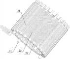
图2为本发明实施例提供的一种侧立磁场电机及应用其的散热风扇结构示意图;Fig. 2 is a schematic structural diagram of a lateral magnetic field motor and a cooling fan using it provided by an embodiment of the present invention;
图3为本发明实施例提供的另一种侧立磁场电机及应用其的散热风扇结构示意图;Fig. 3 is another kind of lateral magnetic field motor provided by the embodiment of the present invention and a structural schematic diagram of a cooling fan using it;
图4为本发明实施例提供的另一种侧立磁场电机的定子结构示意图;Fig. 4 is a schematic structural view of the stator of another side-standing magnetic field motor provided by an embodiment of the present invention;
图5为本发明实施例提供的又一种侧立磁场电机及应用其的散热风扇结构示意图;Fig. 5 is a structural schematic diagram of another side-standing magnetic field motor and a cooling fan using it provided by an embodiment of the present invention;
图6为本发明实施例提供的应用了侧立磁场电机的散热风扇结构示意图。FIG. 6 is a schematic structural diagram of a heat dissipation fan using a side-standing magnetic field motor provided by an embodiment of the present invention.
具体实施方式Detailed ways
下面结合附图对本发明实施例侧立磁场电机进行详细描述。The side-standing magnetic field motor according to the embodiment of the present invention will be described in detail below with reference to the accompanying drawings.
本发明实施例提供一种侧立磁场电机,如图2所示,包括定子,定子包括本体21及设在本体21上的线圈22,侧立磁场电机还包括固定定子的机座23,定子上设有具有传热材质的导热结构;导热结构与机座23相接触并连接。The embodiment of the present invention provides a side-standing magnetic field motor, as shown in Figure 2, including a stator, the stator includes a
本发明实施例提供的侧立磁场电机中,包括有由本体及设在本体上的线圈构成的定子,该定子固定在侧立磁场电机的机座上,且定子上设有传热材质制成的导热结构,该导热结构与机座接触并连接。由此分析可知,通过在本体和/或线圈上设置由传热材质制成的导热结构,能够将线圈工作过程中产生的热量通过线圈自身和/或本体传递到导热结构中,再将热量传递到与导热结构相接触并连接的机座中,由于导热结构由传热材质制成,具有良好的导热性能,能够保证将线圈产生的热量及时、有效地通过导热结构传递到机座中,从而通过机座及时将热量散发到空气中,满足了侧立磁场电机的散热需求,提高了侧立磁场电机的功率密度,实用性高。The side-standing magnetic field motor provided by the embodiment of the present invention includes a stator composed of a body and coils arranged on the body. The heat conduction structure is in contact with and connected to the machine base. From this analysis, it can be seen that by setting a heat-conducting structure made of heat-transfer material on the body and/or the coil, the heat generated during the operation of the coil can be transferred to the heat-conducting structure through the coil itself and/or the body, and then the heat can be transferred In the machine base that is in contact with and connected to the heat-conducting structure, since the heat-conducting structure is made of heat-conducting materials, it has good thermal conductivity, which can ensure that the heat generated by the coil is transferred to the machine base through the heat-conducting structure in a timely and effective manner, thereby The heat is dissipated into the air in time through the base, which meets the heat dissipation requirement of the side-standing magnetic field motor, improves the power density of the side-standing magnetic field motor, and has high practicability.
其中,导热结构在定子上的设置位置和方式不同,其所采用的材质、结构等也不同,但需要保证导热结构为传热性能良好的材质。Among them, the position and method of setting the heat conduction structure on the stator are different, and the materials and structures used are also different, but it is necessary to ensure that the heat conduction structure is a material with good heat transfer performance.
此外,侧立磁场电机通常用于散热风扇(侧立式磁场电机)中,因此,为了便于说明本实施中侧立磁场电机的散热过程及其应用场景,以侧立磁场电机及应用其的散热风扇为例。如图2所示,其中,散热风扇包括风扇框体24,通过支撑架25与风扇框体24固定连接的风扇底座26,风扇底座26与机座23固定连接,侧立磁场电机用于连接风扇叶片(图2中未示出),从而能够驱动风扇叶片转动。在实际应用时,定子本体21可以为电磁性能良好的矽钢片,且本体21通常为筒状结构,可以为圆筒状结构,便于本体21上的线圈22驱动风扇叶片转动。In addition, side-mounted magnetic field motors are usually used in cooling fans (side-mounted magnetic field motors). Therefore, in order to facilitate the description of the heat dissipation process and application scenarios of side-mounted magnetic field motors in this implementation, we use side-mounted magnetic field motors and their heat dissipation Take the fan as an example. As shown in Figure 2, wherein, the cooling fan includes a
具体地,如图2所示,导热结构包括穿设在圆筒状定子本体21中的圆柱状导热柱27,相应的本体21上需要设置容纳该导热柱27的通孔,且导热柱27也可以为长方体、锥形体等结构。图2中,为了保证定子结构的整体性,导热柱27的第一端位于本体21内部,可以与本体21上端面共面设置,导热柱27的第二端凸出于本体21外,从而该端能够插入并固定在机座23中。由此可知,线圈22工作过程中产生的热量首先传递给本体21,再通过本体21传递给传热材质的导热柱27,进而通过导热柱27传递给机座23,最后通过机座23能够传递给与之固定连接的风扇底座26。图2中,风扇底座26中的热量还能够通过支撑架25进行散发,且在图2中,箭头方向为散热风扇工作时产生的气流流动方向,由此可知,该气流能够将支撑架25和风扇底座26中的热量带走,达到快速散热的目的。Specifically, as shown in FIG. 2 , the heat conduction structure includes a cylindrical
其中,机座23、风扇底座26及支撑架25均可以选用导热性能良好的材质,例如金属、陶瓷等。且支撑架25上可以根据结构要求增设散热齿,从而提高支撑架25的散热能力。其中,机座23与风扇底座26可以为两个部件,并通过焊接、过盈配合等方式固定连接;也可以为了缩短热传递路径,将机座23与风扇底座26一体成型设置。Wherein, the
在实际应用时,为了提高导热柱27对热量的传递作用,可以设置多个导热柱27,从而多个导热柱27沿一个本体21的周向方向等距、均匀排布。其中,线圈22在本体21上的布置方式通常为等距、均匀排布,因此可以将导热柱27设在相连线圈组之间,保证整体布置合理性,且导热柱27均匀传递线圈22的热量,避免局部过热的现象。In practical applications, in order to improve the heat transfer effect of the
进一步地,为了提高本体21与导热柱27之间的热交换,通常可以增大两者之间的接触面积,同时保证两者之间为无缝隙接触。具体地,根据本体21的侧壁厚度,可以将导热柱27的直径设为与侧壁厚度相符的数值(直径小于侧壁厚度),同时两者之间通过过盈配合减小缝隙,保证充分接触。其中,导热柱27与本体21之间也可以为焊接方式固定,从而保证两者之间无缝隙,且金属降低了散热的热阻,提高传热能力,进而提高散热能力。Further, in order to improve the heat exchange between the
另外,也可以在导热柱27穿设入本体21中之后,通过在导热柱27与本体21通孔内壁之间填充导热材料,从而在完成导热柱27的固定的同时,提高导热柱27与本体21之间的热传递效率。In addition, after the
导热柱27可以通过焊接的方式固定在机座23上,焊接能够减小散热的热阻,加速散热。当然,导热柱27也可以采用胶粘、过盈配合连接等固定连接。The
此处需要说明的是,图2中,导热柱27还需要穿设过本体21上下端面与线圈22之间的绝缘片。It should be noted here that, in FIG. 2 , the
图2中的散热途径主要通过多个导热柱27及时将热量传递到机座23,进而传递到风扇底座26、支撑架25上等,其散热效率取决于导热柱27的传热效率,因此,此时机座23与风扇底座26可以采用固定连接的方式。当然,也可以通过图3所示的导热结构,具体如下。The heat dissipation approach in Fig. 2 mainly transfers heat to the base 23 in time through a plurality of
图3中,导热结构包括两个环状第一导热架31,两个第一导热架31分别位于定子本体21的上、下端面,且线圈22按现有技术中的方式缠绕在上下第一导热架31与本体21上,如图3所示。由此可知,线圈22工作过程中产生的热量主要通过线圈22传递给本体21,再通过本体21传递给位于本体21下端的第一导热架31,进而传递给与该端第一导热架31固定连接的机座23;还有一部分热量通过线圈22直接传递给第一导热架31,在通过位于本体31下端的第一导热架31传递给机座23。图3中,本体21可以为圆筒状结构,则第一导热架31可以设置为与本体21形状相匹配的圆环状。In Fig. 3, the heat conduction structure includes two ring-shaped first heat conduction frames 31, and the two first heat conduction frames 31 are located on the upper and lower end faces of the
最后通过机座23能够传递给与之固定连接的风扇底座26。图3中,风扇底座26中的热量还能够通过支撑架25进行散发,且在图3中,箭头方向为散热风扇工作时产生的气流流动方向,由此可知,该气流能够将支撑架25和风扇底座26中的热量带走,达到快速散热的目的。Finally, it can be transferred to the
其中,机座23、风扇底座26及支撑架25均可以选用导热性能良好的材质,例如金属、陶瓷等。且支撑架25上可以增设散热齿,从而提高支撑架25的散热能力。其中,机座23与风扇底座26可以为两个部件,并通过焊接、过盈配合等方式固定连接;也可以为了缩短热传递路径,将机座23与风扇底座26一体成型设置;本实施例中由于主要通过位于本体21下端的第一导热架31传递热量,从而为了有效缩短热传递路径,将机座23与风扇底座26一体成型设置,以加快热量的散发。Wherein, the
当通过螺钉连接或粘接配合的方式将位于本体21下端的第一导热架31固定在机座23上时,由于线圈22同时缠绕在第一导热架31上,因此下端区域的线圈22会与机座23相接触,从而线圈22产生的热量还有一部分能够直接传递给机座23,从而通过多方位的散热途径,提高线圈22的散热效率。When the first heat-conducting
为了进一步提高位于本体21下端的第一导热架31的传热效率,可以在不妨碍该端第一导热架31的与机座23固定的同时,在两者之间填充导热材料。同时,还可以在线圈22与机座23之间填充导热材料,便于热量快速的传递。其中,第一导热架31可以采用导热性能很强的AlN陶瓷材料。In order to further improve the heat transfer efficiency of the first
为了进一步保证第一导热架31与机座23的连接稳定性,如图4所示,可以在本体31下端面的第一导热架31上,沿平行于本体31中心线方向设置多个均匀、等距排布的柱状体41,该柱状体41与穿设在机座23中并与机座23固定连接。同时,该些柱状体41还能够起到传热的作用。In order to further ensure the stability of the connection between the first
此处需要说明的是,图3中,位于本体21上下端面的第一导热架31也可以直接作为绝缘片使用,此时位于本体21上端的第一导热架31也能够传热,该部分热量能够通过定子与转子之间的间隙散发。当然,可以在本体21下端设置第一导热架31,上端仍然采用绝缘片结构。It should be noted here that, in FIG. 3 , the first
其中,图3中采用缩短热传递路径的方式,即机座23与风扇底座26一体成型设置,可以减小整体厚度,便于热量快速传递到支撑架上等,该种方式实施简单,有效。此时,机座23也可以称为风扇底座26,或底座。Among them, in Fig. 3, the way of shortening the heat transfer path is adopted, that is, the
在应用磁场电机时,由于主要的发热源为线圈22,则可以通过直接改变线圈22的结构来提高其散热效率,具体如图5所示。When applying a magnetic field motor, since the main heat source is the
图5中,线圈22包括多个间隔设置的条状结构的金属条,导热结构则为设于定子与机座23之间的互连板51,该互连板51与机座23固定连接。其中,由金属条构成的线圈22相比传统绕制线圈22,在相同周向长度下,金属条的截面面积大,电阻小,从而其向下导热能力强,自身发热也小。其中,每个金属条包括两个相互平行的片状体,两个片状体分别贴附在本体21的内、外侧壁上,且两个片状体第一端相连接,第二端通过与互连板51内部的电路实现电连接,从而使金属条和互连板51内部的电路共同形成线圈22的导电通路。In FIG. 5 , the
具体地,互连板51上表面可以设有焊盘,而两个片状体的第二端设有与焊盘固定连接的延伸端。其中焊盘与延伸端一一对应设置,即每个金属条包括有两个延伸端,两个延伸端则分别对应有一个焊盘,且两个延伸端之间不直接相连。这其中,每个金属条的两个延伸端间隔、相背设置,从而使每个金属条构成类似“几”型结构,片状体可以竖直设置、延伸端则垂直于片状体水平设置。图5中,焊盘可以通过电镀或热压的方式固定在互连板51上,且互连板内部还设有与焊盘相连通的电路,该电路可以通过电镀或热压的方式设在互连板51内部,同时通过焊接的方式与焊盘相连,以便后需要与金属条的连接。Specifically, pads may be provided on the upper surface of the
将两个片状体分别贴附在本体21的内、外侧壁时,两个片状体相连接的端部与本体21的顶端面相贴合,此时要求该端部的长度(两个片状体之间的距离)与本体12的厚度相一致。图5中,本体21可以为圆筒状结构,则互连板51可以为中空圆盘状结构,且互连板51的外直径大于本体21直径,从而互连板51便于承载本体21、便于与延伸端固定连接。图5中,每个金属条按上述方式固定在本体21上,同时,多个金属条沿本体21周向方向等距、均匀排布。当然,多个金属条在本体21上的排列方式有多种,图5中的方式为较合理、外观性较整齐的一种布置方式。When the two sheet-like bodies are attached to the inner and outer walls of the
在金属条贴附完成之后,每个金属条均通过各自的焊盘与电路相连通,从而所有的金属条与电路能够共同构成线圈的导电通路,以便于连接外接电源。其中,互连板51内的电路需按照线圈导电通路的连线要求布置。互连板51可以通过胶粘的方式固定在机座23上,且互连板51的材质可以为AlN陶瓷材料。After the metal strips are attached, each metal strip is connected to the circuit through its own pad, so that all the metal strips and the circuit can jointly form the conductive path of the coil, so as to connect to an external power supply. Wherein, the circuits in the
两个片状体分别贴附在本体21侧壁的内、外侧面上,再将延伸端通过焊接的方式固定在焊盘上,从而完成线圈22的固定。由此可知,线圈22产生的热量主要通过线圈22直接传递给焊盘,再通过焊盘传递到互连板51,再通过互连板51传递给机座23。其中,金属条的延伸端与焊盘焊接时,由于焊料的存在,金属条也可以通过焊料与互连板之间传递热量,从而加快线圈22热量的散发。The two sheets are respectively attached to the inner and outer sides of the side wall of the
最后通过机座23能够传递给与之固定连接的风扇底座26。图5中,风扇底座26中的热量还能够通过支撑架25进行散发,且在图5中,箭头方向为散热风扇工作时产生的气流流动方向,由此可知,该气流能够将支撑架25和风扇底座26中的热量带走,达到快速散热的目的。Finally, it can be transferred to the
其中,机座23、风扇底座26及支撑架25均可以选用导热性能良好的材质,例如金属、陶瓷等。且支撑架25上可以增设散热齿,从而提高支撑架25的散热能力。其中,机座23与风扇底座26可以为两个部件,并通过焊接、过盈配合等方式固定连接;也可以为了缩短热传递路径,将机座23与风扇底座26一体成型设置;本实施例中由于主要通过互连板51传递热量,为了有效缩短热传递路径,将机座23与风扇底座26一体成型设置,以加快热量的散发。Wherein, the
图5中,为了拓展线圈22的散热途径,即通过本体21进行部分热量的散发,也可以在本体21的上下端面设置第二导热架52,该第二导热架52可以为与本体21相匹配的圆环状结构。其中位于本体21下端的第二导热架52的上端面与本体21底断面固定连接、下端面则与互连板51相接触和/或连接,从而线圈22的部分热量能够通过本体21传递到位于本体21下端的第二导热架52,再通过该端第二导热架52传递给互连板51,进而传递给机座23等进行快速的热量散发。另外,由于金属条采用贴附方式,因此金属条的底端部分(片状体的第二端)还会与位于本体21底端的第二导热架52的侧表面相接触,增加了传热路径。In Fig. 5, in order to expand the heat dissipation path of the
此处需要说明的是,第二导热架52可以代替本体21上下端面绝缘片。其中,图5中采用缩短热传递路径的方式,即机座23与风扇底座26一体成型设置,可以减小整体厚度,便于热量快速传递到支撑架上等,该种方式实施简单,有效。此时,机座23也可以称为风扇底座26,或底座。It should be noted here that the second
通常,相比现有技术中的侧立磁场电机,采用如图2至图5所示的导热结构,能够有效提高侧立磁场电机的散热效率,同时采用如图2所示的导热结构,能够提高60%的电机功率密度,在采用图3和图5所示的导热结构时,能够提高100%的电机功率密度,实用性高。Generally, compared with the side-standing magnetic field motor in the prior art, adopting the heat conduction structure as shown in Fig. Increase the power density of the motor by 60%. When the heat conduction structure shown in Figure 3 and Figure 5 is used, the power density of the motor can be increased by 100%, and the practicability is high.
本发明实施例还提供一种散热风扇,包括风扇框体、通过支撑架与风扇框体固定连接的风扇底座,及风扇叶片,还包括用于驱动风扇叶片转动的上述实施例描述的侧立磁场电机;侧立磁场电机的机座与风扇底座固定连接。The embodiment of the present invention also provides a cooling fan, which includes a fan frame, a fan base fixedly connected to the fan frame through a support frame, and fan blades, and also includes a lateral magnetic field described in the above embodiments for driving the fan blades to rotate Motor; the base of the side-standing magnetic field motor is fixedly connected with the fan base.
本发明实施例还提供的散热风扇中,由于使用了上述实施例描述的侧立磁场电机,该侧立磁场电机包括有由筒状本体及设在本体上的线圈构成的定子,该定子固定在侧立磁场电机的机座上,且定子上设有导热材质制成的导热结构,该导热结构与机座接触并连接。由此分析可知,通过在本体和/或线圈上设置由传热材质制成的导热结构,能够将线圈工作过程中产生的热量通过线圈自身和/或本体传递到导热结构中,再将热量传递到与导热结构相接触并连接的机座中,由于导热结构由传热材质制成,具有良好的导热性能,能够保证将线圈产生的热量及时、有效地通过导热结构传递到机座中,从而通过机座及时将热量散发到空气中,满足了侧立磁场电机的散热需求,提高了侧立磁场电机的功率密度,实用性高。In the cooling fan provided by the embodiment of the present invention, since the side-standing magnetic field motor described in the above-mentioned embodiments is used, the side-standing magnetic field motor includes a stator composed of a cylindrical body and a coil arranged on the body, and the stator is fixed on Standing sideways on the base of the magnetic field motor, and the stator is provided with a heat conduction structure made of heat conduction material, and the heat conduction structure is in contact with and connected with the base. From this analysis, it can be seen that by setting a heat-conducting structure made of heat-transfer material on the body and/or the coil, the heat generated during the operation of the coil can be transferred to the heat-conducting structure through the coil itself and/or the body, and then the heat can be transferred In the machine base that is in contact with and connected to the heat-conducting structure, since the heat-conducting structure is made of heat-conducting materials, it has good thermal conductivity, which can ensure that the heat generated by the coil is transferred to the machine base through the heat-conducting structure in a timely and effective manner, thereby The heat is dissipated into the air in time through the base, which meets the heat dissipation requirement of the side-standing magnetic field motor, improves the power density of the side-standing magnetic field motor, and has high practicability.
其中,机座与风扇底座之间可以通过焊接或过盈配合固定连接;或,机座与风扇底座为一体成型结构,如果选择为后者,能够缩短传热路径。根据侧立磁场电机不同的导热结构,可以选择机座与风扇底座不同的连接结构,应用广泛,且该种选择方式在上述实施例中已进行描述,再次不在赘述。Wherein, the machine base and the fan base can be fixedly connected by welding or interference fit; or, the machine base and the fan base are integrally formed, and if the latter is selected, the heat transfer path can be shortened. According to the different heat conduction structures of the side-standing magnetic field motors, different connection structures between the machine base and the fan base can be selected, which are widely used, and this selection method has been described in the above-mentioned embodiments, and will not be described again.
进一步地,支撑架上可以设有散热齿结构,从而加快热量在支撑架位置处的散发,从而提高整体散热效率。散热齿结构可以根据需要而设定。Further, the support frame may be provided with a heat dissipation tooth structure, so as to accelerate heat dissipation at the position of the support frame, thereby improving the overall heat dissipation efficiency. The cooling tooth structure can be set according to needs.
其中,图6为应用了侧立磁场电机62的散热风扇61。Wherein, FIG. 6 shows a heat dissipation fan 61 using a lateral magnetic field motor 62 .
在本发明的描述中,需要理解的是,术语“中心”、“上”、“下”、“前”、“后”、“左”、“右”、“竖直”、“水平”、“顶”、“底”、“内”、“外”等指示的方位或位置关系为基于附图所示的方位或位置关系,仅是为了便于描述本发明和简化描述,而不是指示或暗示所指的装置或元件必须具有特定的方位、以特定的方位构造和操作,因此不能理解为对本发明的限制。In describing the present invention, it is to be understood that the terms "center", "upper", "lower", "front", "rear", "left", "right", "vertical", "horizontal", The orientations or positional relationships indicated by "top", "bottom", "inner", "outer", etc. are based on the orientations or positional relationships shown in the drawings, and are only for the convenience of describing the present invention and simplifying the description, rather than indicating or implying References to devices or elements must have a particular orientation, be constructed, and operate in a particular orientation and therefore should not be construed as limiting the invention.
术语“第一”、“第二”仅用于描述目的,而不能理解为指示或暗示相对重要性或者隐含指明所指示的技术特征的数量。由此,限定有“第一”、“第二”的特征可以明示或者隐含地包括一个或者更多个该特征。在本发明的描述中,除非另有说明,“多个”的含义是两个或两个以上。The terms "first" and "second" are used for descriptive purposes only, and cannot be understood as indicating or implying relative importance or implicitly specifying the quantity of indicated technical features. Thus, a feature defined as "first" and "second" may explicitly or implicitly include one or more of these features. In the description of the present invention, unless otherwise specified, "plurality" means two or more.
在本发明的描述中,需要说明的是,除非另有明确的规定和限定,术语“安装”、“相连”、“连接”应做广义理解,例如,可以是固定连接,也可以是可拆卸连接,或一体地连接;可以是机械连接,也可以是电连接;可以是直接相连,也可以通过中间媒介间接相连,可以是两个元件内部的连通。对于本领域的普通技术人员而言,可以具体情况理解上述术语在本发明中的具体含义。In the description of the present invention, it should be noted that unless otherwise specified and limited, the terms "installation", "connection" and "connection" should be understood in a broad sense, for example, it can be a fixed connection or a detachable connection. Connected, or integrally connected; it can be mechanically connected or electrically connected; it can be directly connected or indirectly connected through an intermediary, and it can be the internal communication of two components. Those of ordinary skill in the art can understand the specific meanings of the above terms in the present invention in specific situations.
在本说明书的描述中,具体特征、结构、材料或者特点可以在任何的一个或多个实施例或示例中以合适的方式结合。In the description of this specification, specific features, structures, materials or characteristics may be combined in any one or more embodiments or examples in an appropriate manner.
以上所述,仅为本发明的具体实施方式,但本发明的保护范围并不局限于此,任何熟悉本技术领域的技术人员在本发明揭露的技术范围内,可轻易想到变化或替换,都应涵盖在本发明的保护范围之内。因此,本发明的保护范围应所述以权利要求的保护范围为准。The above is only a specific embodiment of the present invention, but the scope of protection of the present invention is not limited thereto. Anyone skilled in the art can easily think of changes or substitutions within the technical scope disclosed in the present invention. Should be covered within the protection scope of the present invention. Therefore, the protection scope of the present invention should be based on the protection scope of the claims.
Claims (24)
Priority Applications (5)
| Application Number | Priority Date | Filing Date | Title |
|---|---|---|---|
| CN201310753140.1ACN103746471B (en) | 2013-12-31 | 2013-12-31 | Edge-on magnetic field electric motor and apply its radiator fan |
| EP14875931.9AEP2985889B1 (en) | 2013-12-31 | 2014-07-10 | Side-standing magnetic field motor and cooling fan using same |
| BR112016015445ABR112016015445A8 (en) | 2013-12-31 | 2014-07-10 | side magnetic motor and cooling fan using side magnetic motor |
| PCT/CN2014/081965WO2015101005A1 (en) | 2013-12-31 | 2014-07-10 | Side-standing magnetic field motor and cooling fan using same |
| US14/980,609US10079527B2 (en) | 2013-12-31 | 2015-12-28 | Side stand magnetic motor and cooling fan using side stand magnetic motor |
Applications Claiming Priority (1)
| Application Number | Priority Date | Filing Date | Title |
|---|---|---|---|
| CN201310753140.1ACN103746471B (en) | 2013-12-31 | 2013-12-31 | Edge-on magnetic field electric motor and apply its radiator fan |
Publications (2)
| Publication Number | Publication Date |
|---|---|
| CN103746471Atrue CN103746471A (en) | 2014-04-23 |
| CN103746471B CN103746471B (en) | 2017-10-17 |
Family
ID=50503474
Family Applications (1)
| Application Number | Title | Priority Date | Filing Date |
|---|---|---|---|
| CN201310753140.1AActiveCN103746471B (en) | 2013-12-31 | 2013-12-31 | Edge-on magnetic field electric motor and apply its radiator fan |
Country Status (5)
| Country | Link |
|---|---|
| US (1) | US10079527B2 (en) |
| EP (1) | EP2985889B1 (en) |
| CN (1) | CN103746471B (en) |
| BR (1) | BR112016015445A8 (en) |
| WO (1) | WO2015101005A1 (en) |
Cited By (6)
| Publication number | Priority date | Publication date | Assignee | Title |
|---|---|---|---|---|
| WO2015101005A1 (en)* | 2013-12-31 | 2015-07-09 | 华为技术有限公司 | Side-standing magnetic field motor and cooling fan using same |
| CN106533061A (en)* | 2016-12-13 | 2017-03-22 | 中国工程物理研究院激光聚变研究中心 | Vacuum motor heat conductor |
| CN109818457A (en)* | 2019-03-18 | 2019-05-28 | 扬州市华胜机电制造有限公司 | A kind of heat dissipation brushless motor certainly |
| CN110535292A (en)* | 2018-05-23 | 2019-12-03 | 上海鸣志电器股份有限公司 | A kind of low-temperature lifting motor structure |
| CN113014041A (en)* | 2016-06-23 | 2021-06-22 | 萨卢奇控股有限公司 | Brushless motor system comprising rotor, stator and power electronic device |
| CN113098177A (en)* | 2021-04-07 | 2021-07-09 | 清华大学 | Stator heat dissipation structure for inner rotor motor, inner rotor motor and ducted fan |
Families Citing this family (2)
| Publication number | Priority date | Publication date | Assignee | Title |
|---|---|---|---|---|
| EP3333688B1 (en) | 2016-12-08 | 2020-09-02 | LG Electronics Inc. | Mobile terminal and method for controlling the same |
| CN117614186B (en)* | 2023-12-05 | 2024-05-14 | 江苏微特利电机股份有限公司 | Permanent magnet motor system for pure electric logistics vehicle and installation method thereof |
Citations (10)
| Publication number | Priority date | Publication date | Assignee | Title |
|---|---|---|---|---|
| EP1257043A2 (en)* | 2001-05-11 | 2002-11-13 | Switched Reluctance Drives Limited | Cooling of electrical machines |
| JP2003052142A (en)* | 2001-08-03 | 2003-02-21 | Matsushita Electric Ind Co Ltd | Electric motor |
| US20070145842A1 (en)* | 2005-12-23 | 2007-06-28 | Delta Electronics, Inc. | Fan and motor thereof |
| US20100026108A1 (en)* | 2006-06-19 | 2010-02-04 | Thermal Motor Innovations, Llc | Electric motor with heat pipes |
| CN1976177B (en)* | 2005-11-29 | 2010-07-21 | 日本电产株式会社 | Motor |
| CN102340208A (en)* | 2010-07-15 | 2012-02-01 | 建准电机工业股份有限公司 | Motor and cooling fan with the same |
| US20120085519A1 (en)* | 2010-10-12 | 2012-04-12 | Chou Chu-Hsien | Heat-dissipating structure for motor stator |
| CN101669267B (en)* | 2007-06-06 | 2012-09-05 | 株式会社安川电机 | Revolving electric device, and its manufacturing method |
| US8376072B2 (en)* | 2008-12-26 | 2013-02-19 | Sanyo Electric Co., Ltd. | Molded motor and electric vehicle |
| CN102957268A (en)* | 2011-08-17 | 2013-03-06 | 大银微系统股份有限公司 | Heat dissipation structure for rotary motor |
Family Cites Families (9)
| Publication number | Priority date | Publication date | Assignee | Title |
|---|---|---|---|---|
| JP4716065B2 (en)* | 2000-06-21 | 2011-07-06 | ミネベア株式会社 | Axial blower |
| WO2007043119A1 (en)* | 2005-09-30 | 2007-04-19 | Fujitsu Limited | Fan device |
| CN2901677Y (en)* | 2005-11-10 | 2007-05-16 | 江苏三江电器集团有限公司 | Structure for directly heat conducting between motor winding and end lid casing |
| JP2008178190A (en)* | 2007-01-17 | 2008-07-31 | Tamagawa Seiki Co Ltd | Stator structure |
| US8540497B2 (en)* | 2010-08-13 | 2013-09-24 | Asia Vital Components Co., Ltd. | Fan self-cooling structure with heat pipe |
| DE202010017101U1 (en)* | 2010-12-28 | 2011-02-24 | Asia Vital Components Co., Ltd., Hsin Chuan City | Cooling structure of a moisture and dustproof fan motor and its fan |
| TWM425456U (en)* | 2011-10-26 | 2012-03-21 | Teco Electric & Machinery Co Ltd | Periphery structure of motor |
| US8760018B2 (en)* | 2012-01-20 | 2014-06-24 | Asia Vital Components Co., Ltd. | Motor stator with heat dissipation structure |
| CN103746471B (en)* | 2013-12-31 | 2017-10-17 | 华为技术有限公司 | Edge-on magnetic field electric motor and apply its radiator fan |
- 2013
- 2013-12-31CNCN201310753140.1Apatent/CN103746471B/enactiveActive
- 2014
- 2014-07-10WOPCT/CN2014/081965patent/WO2015101005A1/enactiveApplication Filing
- 2014-07-10BRBR112016015445Apatent/BR112016015445A8/ennot_activeApplication Discontinuation
- 2014-07-10EPEP14875931.9Apatent/EP2985889B1/enactiveActive
- 2015
- 2015-12-28USUS14/980,609patent/US10079527B2/enactiveActive
Patent Citations (10)
| Publication number | Priority date | Publication date | Assignee | Title |
|---|---|---|---|---|
| EP1257043A2 (en)* | 2001-05-11 | 2002-11-13 | Switched Reluctance Drives Limited | Cooling of electrical machines |
| JP2003052142A (en)* | 2001-08-03 | 2003-02-21 | Matsushita Electric Ind Co Ltd | Electric motor |
| CN1976177B (en)* | 2005-11-29 | 2010-07-21 | 日本电产株式会社 | Motor |
| US20070145842A1 (en)* | 2005-12-23 | 2007-06-28 | Delta Electronics, Inc. | Fan and motor thereof |
| US20100026108A1 (en)* | 2006-06-19 | 2010-02-04 | Thermal Motor Innovations, Llc | Electric motor with heat pipes |
| CN101669267B (en)* | 2007-06-06 | 2012-09-05 | 株式会社安川电机 | Revolving electric device, and its manufacturing method |
| US8376072B2 (en)* | 2008-12-26 | 2013-02-19 | Sanyo Electric Co., Ltd. | Molded motor and electric vehicle |
| CN102340208A (en)* | 2010-07-15 | 2012-02-01 | 建准电机工业股份有限公司 | Motor and cooling fan with the same |
| US20120085519A1 (en)* | 2010-10-12 | 2012-04-12 | Chou Chu-Hsien | Heat-dissipating structure for motor stator |
| CN102957268A (en)* | 2011-08-17 | 2013-03-06 | 大银微系统股份有限公司 | Heat dissipation structure for rotary motor |
Cited By (8)
| Publication number | Priority date | Publication date | Assignee | Title |
|---|---|---|---|---|
| WO2015101005A1 (en)* | 2013-12-31 | 2015-07-09 | 华为技术有限公司 | Side-standing magnetic field motor and cooling fan using same |
| US10079527B2 (en) | 2013-12-31 | 2018-09-18 | Huawei Technologies Co., Ltd. | Side stand magnetic motor and cooling fan using side stand magnetic motor |
| CN113014041A (en)* | 2016-06-23 | 2021-06-22 | 萨卢奇控股有限公司 | Brushless motor system comprising rotor, stator and power electronic device |
| CN106533061A (en)* | 2016-12-13 | 2017-03-22 | 中国工程物理研究院激光聚变研究中心 | Vacuum motor heat conductor |
| CN106533061B (en)* | 2016-12-13 | 2023-08-08 | 中国工程物理研究院激光聚变研究中心 | Vacuum motor heat conductor |
| CN110535292A (en)* | 2018-05-23 | 2019-12-03 | 上海鸣志电器股份有限公司 | A kind of low-temperature lifting motor structure |
| CN109818457A (en)* | 2019-03-18 | 2019-05-28 | 扬州市华胜机电制造有限公司 | A kind of heat dissipation brushless motor certainly |
| CN113098177A (en)* | 2021-04-07 | 2021-07-09 | 清华大学 | Stator heat dissipation structure for inner rotor motor, inner rotor motor and ducted fan |
Also Published As
| Publication number | Publication date |
|---|---|
| CN103746471B (en) | 2017-10-17 |
| WO2015101005A1 (en) | 2015-07-09 |
| US10079527B2 (en) | 2018-09-18 |
| EP2985889B1 (en) | 2017-12-20 |
| BR112016015445A2 (en) | 2017-08-08 |
| EP2985889A1 (en) | 2016-02-17 |
| BR112016015445A8 (en) | 2020-06-09 |
| EP2985889A4 (en) | 2016-06-08 |
| US20160111939A1 (en) | 2016-04-21 |
Similar Documents
| Publication | Publication Date | Title |
|---|---|---|
| CN103746471B (en) | Edge-on magnetic field electric motor and apply its radiator fan | |
| CN103081326B (en) | Inverter unit | |
| JP6371001B2 (en) | Power converter | |
| CN107852071B (en) | Rotary motor | |
| JP7156265B2 (en) | pumping equipment | |
| CN102891564B (en) | rotating electrical machine | |
| CN105990284A (en) | Semiconductor device | |
| JP2021097590A (en) | Wireless charging device | |
| CN104242048B (en) | Packaging structure of conduction-cooled stack semiconductor laser | |
| JP2013099213A (en) | Inverter device | |
| JP2004282804A (en) | Inverter device | |
| CN102340208A (en) | Motor and cooling fan with the same | |
| CN111133401B (en) | data processing equipment | |
| CN114844270A (en) | A stator assembly and motor | |
| US11043878B2 (en) | Stator assembly for cooling an electric motor | |
| CN101951115A (en) | Permanent magnet linear synchronous motor | |
| US20200100393A1 (en) | Motor, printed circuit board, and engine cooling fan module including the motor | |
| CN110581625A (en) | heat radiation structure of motor stator winding | |
| US11121606B2 (en) | Motor, circuit board, and engine cooling module including the motor | |
| CN207234480U (en) | Wireless charging device | |
| JP2016101071A (en) | Semiconductor device | |
| JP2017085718A (en) | motor | |
| CN103747395B (en) | Ultrathin loudspeaker formula radiator and damping ultrathin radiator | |
| CN203590431U (en) | Ultrathin loudspeaker-type radiator and damping ultrathin radiator | |
| CN115831550A (en) | Heat radiation structure and electronic equipment |
Legal Events
| Date | Code | Title | Description |
|---|---|---|---|
| C06 | Publication | ||
| PB01 | Publication | ||
| C10 | Entry into substantive examination | ||
| SE01 | Entry into force of request for substantive examination | ||
| GR01 | Patent grant | ||
| GR01 | Patent grant |