CN103733147A - Method for switching in an arrangement of circuit breakers and arrangement of a plurality of circuit breakers - Google Patents
Method for switching in an arrangement of circuit breakers and arrangement of a plurality of circuit breakersDownload PDFInfo
- Publication number
- CN103733147A CN103733147ACN201280039693.4ACN201280039693ACN103733147ACN 103733147 ACN103733147 ACN 103733147ACN 201280039693 ACN201280039693 ACN 201280039693ACN 103733147 ACN103733147 ACN 103733147A
- Authority
- CN
- China
- Prior art keywords
- power switch
- switching
- power
- switch
- switches
- Prior art date
- Legal status (The legal status is an assumption and is not a legal conclusion. Google has not performed a legal analysis and makes no representation as to the accuracy of the status listed.)
- Granted
Links
- 238000000034methodMethods0.000titleclaimsdescription19
- 238000004092self-diagnosisMethods0.000claimsdescription3
- 238000004891communicationMethods0.000description2
- 238000012544monitoring processMethods0.000description2
- 230000001960triggered effectEffects0.000description2
- 230000005540biological transmissionEffects0.000description1
- 238000001514detection methodMethods0.000description1
- 230000000694effectsEffects0.000description1
- 238000009434installationMethods0.000description1
Images
Classifications
- G—PHYSICS
- G05—CONTROLLING; REGULATING
- G05B—CONTROL OR REGULATING SYSTEMS IN GENERAL; FUNCTIONAL ELEMENTS OF SUCH SYSTEMS; MONITORING OR TESTING ARRANGEMENTS FOR SUCH SYSTEMS OR ELEMENTS
- G05B9/00—Safety arrangements
- G05B9/02—Safety arrangements electric
- G05B9/03—Safety arrangements electric with multiple-channel loop, i.e. redundant control systems
Landscapes
- Physics & Mathematics (AREA)
- General Physics & Mathematics (AREA)
- Engineering & Computer Science (AREA)
- Automation & Control Theory (AREA)
- Remote Monitoring And Control Of Power-Distribution Networks (AREA)
- Power Sources (AREA)
- Direct Current Feeding And Distribution (AREA)
Abstract
Translated fromChinese
Description
Translated fromChinese技术领域technical field
本发明涉及一种用于在功率开关构成的设备中进行开关的方法,其中在本发明中应当将这样的设备理解成,功率开关被互相串联和/或并联连接。功率开关的特征应当是,由数据处理装置控制实际的开关单元,其中该数据处理装置典型地被构造成微控制器。借助这样的微控制器,功率开关可以处理逻辑任务。特别是还可以提供自诊断功能。The invention relates to a method for switching in an arrangement of power switches, wherein in the context of the invention such an arrangement is understood to mean that power switches are connected in series and/or in parallel with one another. A power switch should be characterized in that the actual switching unit is controlled by a data processing device, wherein the data processing device is typically designed as a microcontroller. With such a microcontroller, the power switch can handle logic tasks. In particular, a self-diagnostic function can also be provided.
背景技术Background technique
在所述类型的设备中应当具有高安全性的效果,即实际地接通要接通的功率开关,并且实际地关断要关断的功率开关。至今在能量分配设备中通过上级系统实现了这样的安全接通和关断。该系统包括多个测量传感器,其在设备的多个部分中测量各自流过的电流。另外可以向功率开关的具有通信能力的部分请求开关数据和开关值。通常由控制室来控制这样作为上级系统构造的监控系统,在该控制室中自动地或由技术员手动地在故障情况下,即不能执行预期的开关操作的情况下,导入应对措施。In a device of this type there should be a high safety effect of actually switching on the power switch that is to be switched on and actually switching off the power switch that is to be switched off. Such safe switching on and off has hitherto been implemented in energy distribution systems by superordinate systems. The system includes a plurality of measuring sensors which measure the respective currents flowing in the various parts of the device. In addition, switching data and switching values can be requested from communication-capable parts of the power switch. Such a monitoring system, which is designed as a superordinated system, is usually controlled by a control room, in which countermeasures are initiated automatically or manually by a technician in the event of a fault, ie if the intended switching operation cannot be carried out.
使用这种监控系统伴随着巨大费用。对执行应对措施的自动化是困难的,然而手动地执行应对措施也是危险的,因为可能发生人为失误。The use of such monitoring systems is associated with significant costs. Automating the execution of countermeasures is difficult, yet performing the countermeasures manually is also dangerous since human error may occur.
发明内容Contents of the invention
因此,本发明要解决的技术问题是,提供一种用于在所提及类型的功率开关的设备中进行开关的方法,其中更大程度地保证,可靠地接通或关断能量分配设备的单个支路。The technical problem to be solved by the present invention is therefore to provide a method for switching in a power switching device of the mentioned type, in which it is ensured to a greater extent that the switching on or off of the energy distribution device is reliable. single branch.
该技术问题一方面通过具有按照权利要求1的特征的方法解决,另一方面通过具有按照权利要求6的特征的设备解决。The technical problem is solved on the one hand by a method having the features according to claim 1 and on the other hand by a device having the features according to claim 6 .
根据本发明的方法包括以下步骤:The method according to the invention comprises the following steps:
-通过第一功率开关的数据处理装置来控制第一功率开关的开关单元,用于改变其开关状态;- controlling the switching unit of the first power switch through the data processing device of the first power switch for changing its switching state;
-采集是否(通过数据处理装置)发生了开关状态的改变,如果是,则可以结束本方法。目前感兴趣的情况是,未发生开关状态的改变,因为然后通过如下步骤继续本方法:- It is detected (by the data processing device) whether a change of the switching state has occurred, if so, the method can be terminated. The presently interesting situation is that no change of state of the switch has taken place, because the method is then continued with the following steps:
-通过第一功率开关的数据处理装置向第二功率开关的数据处理装置发送信号;- sending a signal via the data processing means of the first power switch to the data processing means of the second power switch;
-通过第二功率开关的数据处理装置来控制第二功率开关的开关单元,用于改变其开关状态。- controlling the switching unit of the second power switch by means of the data processing device of the second power switch for changing its switching state.
本方面一方面出于考虑,功率开关可能故障,即它不再能够自身可靠地接通和断开,而是必须由其它的功率开关接通和断开,以便替代预期的开关过程。特别点现在在于,功率开关本身互相通信,使得不必再绕路经过控制室给出:功率开关自身识别到,它不能如预期那样改变它的开关单元的开关状态,将这个通过信号通知其它功率开关,并且替代性地然后接通(schalten)其自身。以这种方式保证了在能量分配设备中的支路的可靠接通和关断。On the one hand, this aspect is based on the consideration that a power switch may fail, ie it can no longer be switched on and off reliably by itself, but must be switched on and off by another power switch in order to replace the intended switching process. The special point now is that the power switches themselves communicate with each other, so that detours through the control room are no longer necessary given that the power switch itself recognizes that it cannot change the switching state of its switching unit as expected and signals this to the other power switches , and alternatively then switch on (schalten) itself. In this way, reliable switching on and off of the branch circuits in the energy distribution system is guaranteed.
在本发明的替代方案中,为了关断(即,开关触点应当断开,以便电流不再能够经过其并因此不再能够经过功率开关流动)而控制开关单元。这这种情况下,向与第一功率开关串联连接的第二功率开关发送信号。在此,代替通过目标明确的发送来选择该第二功率开关,可以向全部功率开关发送信号,而第二功率开关可以根据信号的类型(例如在其中包含的地址)或者也可以根据发送者(第一功率开关)的识别符识别到,它自身对于发送(信号)的第一功率开关应当起到作为第二功率开关的作用。第二功率开关与第一功率开关是串联连接的在关断时是重要的,因为在关断后在整个支路中不应当再流过电流。In an alternative of the invention, the switching unit is controlled for switching off, ie the switching contact should be opened so that current can no longer flow through it and thus through the power switch. In this case, a signal is sent to a second power switch connected in series with the first power switch. In this case, instead of selecting the second power switch by a targeted transmission, a signal can be sent to all power switches, and the second power switch can depend on the type of the signal (for example the address contained therein) or also on the basis of the sender ( The identifier of the first power switch) recognizes that it should function as a second power switch for the first power switch that sends (signals). The fact that the second power switch is connected in series with the first power switch is important when switching off, since no current should flow in the entire branch after switching off.
相反有效的是:如果为了接通(以便电流流过)而控制开关单元,则选择或自行激活与第一功率开关并联连接的第二功率开关。因为对于电流流动,并联电路保证冗余(Redundanz)。Instead, it is effective if the switching unit is actuated for switching on (for current flow) to select or activate itself a second power switch connected in parallel to the first power switch. Because for current flow, parallel circuits guarantee redundancy (Redundanz).
如果应当从外部触发开关状态的改变,即在由第一功率开关从外部接收到相应的信号之后,由该信号要求了第一功率开关的开关单元的开关状态的改变,则可以执行根据本发明的方法。如果第一功率开关的数据处理装置识别到满足(Bestehen)(预定的)条件,其按照预定的标准需要改变开关状态,并且如果功率开关有效在这种情况下其也自动触发、开关状态本身也改变,则同样可以使用本方法。If the change of the switching state is to be triggered externally, ie after a corresponding signal has been received by the first power switch from the outside, which requires a change of the switching state of the switching unit of the first power switch, then the method according to the invention can be carried out. Methods. If the data processing device of the first power switch recognizes that a (predetermined) condition is fulfilled, it needs to change the switching state according to a predetermined criterion, and if the power switch is active in this case it is also triggered automatically, the switching state itself If changed, this method can also be used.
在根据本发明的由多个串联和/或并联连接的功率开关构成的设备中,功率开关至少部分地通过数据网络互相耦接;具有至少一个能够发送这种信号的第一功率开关;对于该信号至少一个第二功率开关能够根据接收信号改变它自身的开关状态。换言之,至少一对第一和第二功率开关通过数据网络能够如下地通信,使得一个功率开关能够触发另一个功率开关改变开关状态。In a device according to the invention consisting of a plurality of power switches connected in series and/or in parallel, the power switches are at least partially coupled to each other via a data network; there is at least one first power switch capable of sending such a signal; for the Signal The at least one second power switch is capable of changing its own switching state according to the received signal. In other words, at least one pair of first and second power switches can communicate over the data network such that one power switch can trigger the other power switch to change the switching state.
在此,优选至少一个第一功率开关具有自诊断能力。在自诊断的范围内采集,是否根据控制命令发生了控制单元的控制状态的改变,如果尽管给出控制命令还未发生,则具有自诊断能力的第一功率开关正好能够发送上述的信号,该信号被至少一个第二功率开关解释为,该第二功率开关应当改变其自身的开关状态。Here, preferably at least one first power switch has self-diagnostic capability. In the scope of the self-diagnosis it is determined whether a change in the control state of the control unit has occurred in accordance with the control command, if this has not occurred despite the control command being given, the first power switch with self-diagnosis capability is precisely able to send the above-mentioned signal, the The signal is interpreted by at least one second power switch as indicating that the second power switch should change its own switching state.
附图说明Description of drawings
以下结合附图详细描述本发明的优选实施方式,其中:Preferred embodiments of the present invention are described in detail below in conjunction with accompanying drawings, wherein:
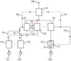
图1示出了根据本发明的以串联和并联互相连接的功率开关的设备,其可以实现根据本发明的方法。FIG. 1 shows an arrangement according to the invention of power switches interconnected in series and in parallel, which can implement the method according to the invention.
具体实施方式Detailed ways
在例如与公共电流网络耦接的能量分配设备中,多个功率开关S1、S2、S2′、S2′′、S3、S3′、S3′′互相耦接,并且以分级形式呈现出三个等级。在此通过实线示出了电连接。功率开关同时通过数据网络互相耦接,这通过虚线示出。In an energy distribution installation, for example, coupled to a common current network, a plurality of power switches S1, S2, S2', S2'', S3, S3', S3'' are coupled to each other and present three levels in hierarchical form . The electrical connections are shown here by solid lines. The power switches are simultaneously coupled to each other via a data network, which is indicated by dashed lines.
电流可以从电流网络NW经过第一等级的功率开关S1、第二等级的功率开关S2和第三等级的功率开关S3的串联电路流到第一用电器支路VZ1。在第二等级中,与功率开关S2并联地还连接有另外的功率开关S2′。因此,同样也有功率开关S1、S2′和S3到用电器支路VZ1的连接。Current can flow from the current network NW to the first consumer branch VZ1 via the series connection of the first-order power switch S1 , the second-order power switch S2 and the third-order power switch S3 . In the second stage, a further power switch S2' is connected in parallel to the power switch S2. Therefore, there is likewise a connection of power switches S1 , S2 ′ and S3 to consumer branch VZ1 .
用电器支路VZ2经过第一等级的功率开关S1、第二等级的互相并联的两个功率开关S2和S2′以及第三等级的功率开关S3′与网络NW耦接。The consumer branch VZ2 is coupled to the network NW via a power switch S1 of the first class, two power switches S2 and S2' connected in parallel of the second class and a power switch S3' of the third class.
最后,用电器支路VZ3经过第一等级的功率开关S1、第二等级的另外的功率开关S2′′和第三等级的另外的功率开关S3′′与网络NW连接。Finally, consumer branch VZ3 is connected to network NW via a first-level power switch S1 , a second-level further power switch S2 ″ and a third-level further power switch S3 ″.
如同仅在功率开关S3′′示出的那样,每个功率开关具有实际的开关单元SE,即由两个互相连接的接触元件构成的单元,该接触元件能够互相分离,以便断开开关。因此,开关单元在触点分离时关断,在触点接触时接通。此处,应当能够由微控制器μC控制功率开关。在图1的符号中,微控制器μC间接与通过虚线表示的通信路径相对应,而开关单元SE与通过实线表示的电流路径相对应。As only shown for power switch S3 ″, each power switch has an actual switching element SE, ie a unit consisting of two interconnected contact elements which can be separated from each other in order to open the switch. Therefore, the switching unit is turned off when the contacts are separated and turned on when the contacts are in contact. Here, it should be possible to control the power switch by the microcontroller μC. In the symbol of FIG. 1 , the microcontroller μC indirectly corresponds to the communication path indicated by the dotted line, while the switching unit SE corresponds to the current path indicated by the solid line.
首先要讨论的情况是,在开关S1闭合并且开关S3和S3′闭合的情况下,应当通过闭合第二等级的开关S2和S2′之一来接通用电器支路VZ1和VZ2。The first case to be discussed is that, with switch S1 closed and switches S3 and S3 ′ closed, consumer branches VZ1 and VZ2 are to be switched on by closing one of the second-level switches S2 and S2 ′.
开关S2例如从外部接收到相应的控制命令,并且功率开关S2的数据处理装置控制所属的开关单元,使该开关单元闭合。功率开关S2现在配备有自诊断能力,并且能够采集,是否预期改变了开关状态,即是否发生了开关单元的闭合或者说接通。如果是,则如希望的那样实现了网络NW与用电器支路VZ1和VZ2之间的连接。如果相反地,开关S2有故障并因此不能实现接通,则功率开关S2作为第二等级的第一功率开关向与它并联连接的同等级的第二功率开关S2′发送相应的信号。第二功率开关S2′的数据处理装置(微控制器)接收该信号,并且通过控制第二功率开关S2′的开关单元,导致其现在自行闭合或者说接通。The switch S2 receives a corresponding control command from the outside, for example, and the data processing device of the power switch S2 controls the associated switch unit to close the switch unit. The power switch S2 is now equipped with a self-diagnostic capability and can detect whether a change in the switching state is expected, ie whether a closing or switching of the switching unit has occurred. If yes, the connection between the network NW and the consumer branches VZ1 and VZ2 has taken place as desired. If, on the other hand, switch S2 is faulty and therefore cannot be switched on, power switch S2 , as the first power switch of the second class, sends a corresponding signal to its parallel-connected second power switch S2 ′ of the same class. The data processing unit (microcontroller) of the second power switch S2 ′ receives this signal and, by controlling the switching unit of the second power switch S2 ′, causes it to now close or switch on itself.
因此,通过互相并联连接的第一和第二功率开关S2和S2′的设备保证了冗余,并且该冗余通过关于数据网络的通信被利用,因此第一功率开关按照箭头P1向第二功率开关S2′发送相应的信号。Redundancy is thus ensured by the arrangement of the first and second power switches S2 and S2' connected in parallel with each other, and this redundancy is exploited by communication on the data network, so that the first power switch supplies power to the second power switch according to arrow P1 Switch S2' sends a corresponding signal.
相反,可能的是,首先应当闭合作为第一功率开关的功率开关S2′,如果它不这么做,则向现在作为第二功率开关的功率开关S2发送相应的信号P2,于是至少使其闭合。Instead, it is possible that first the power switch S2' as the first power switch should be closed, and if it does not, a corresponding signal P2 is sent to the power switch S2 now as the second power switch, which then at least closes it.
也可以多于两个功率开关S2、S2′互相并联连接,以便以更高的程度保证冗余,并且也可以经受得起多于一个功率开关故障的情况。It is also possible for more than two power switches S2, S2' to be connected in parallel with each other in order to ensure redundancy to a higher degree and also to withstand the failure of more than one power switch.
现在转入关断的情况:Now turning to the shutdown case:
例如应当将用电器支路VZ3从网络NW分离,为此通常关断位于最近的功率开关S3′′。For example, the consumer branch VZ3 is to be disconnected from the network NW, for which purpose the nearest power switch S3 ″ is usually switched off.
这里也可以进行外部的触发,但是也可以是功率开关S3′′由于采集到故障电流或过电流而自动地希望关断。因此,第三等级的功率开关S3′′的微控制器μC(数据处理装置)控制所属的开关单元SE。现在作为第一功率开关的功率开关S3′′也能够执行自诊断。如果如期望那样进行了关断,则用电器支路VZ3成功地与网络NW分离。如果未进行关断并因此功率开关S3′′不具有完整功能,则该功率开关向与其串联连接的功率开关S2′′发送信号P3。功率开关S2′′现在起到第二功率开关的作用,其接收信号并通过它的微控制器向它自己的开关单元给出控制命令。An external trigger is also possible here, but it is also possible for the power switch S3 ″ to be switched off automatically due to the detection of a fault current or an overcurrent. The microcontroller μC (data processing unit) of the power switch S3 ″ of the third stage thus controls the associated switching unit SE. Power switch S3 ″ as the first power switch is now also able to carry out self-diagnostics. If the shutdown takes place as expected, the consumer branch VZ3 is successfully disconnected from the network NW. If the switch-off is not taking place and therefore the power switch S3 ″ is not fully functional, it sends a signal P3 to the power switch S2 ″ connected in series with it. The power switch S2'' now acts as a second power switch which receives the signal and gives control commands to its own switching unit via its microcontroller.
现在也将第二功率开关S2′′构造用于自诊断,并且可以采集,是否现在成功地进行了关断。如果关断了第二等级的功率开关S2′′,则现在在这里的第二尝试中成功地中断了网络NW与用电器支路VZ3之间的连接。The second power switch S2 ″ is now also configured for self-diagnostics and it can be determined whether the shutdown has now been successfully performed. If the power switch S2 ″ of the second stage is switched off, the connection between the network NW and the consumer branch VZ3 is now successfully interrupted in the second attempt here.
如果不是,则功率开关S2′′就其而言再次作为第一功率开关向第一等级的功率开关S1发送信号P4,并且导致现在触发功率开关S1。If not, power switch S2 ″ sends signal P4 again as the first power switch for its part to power switch S1 of the first stage and causes power switch S1 to be actuated now.
因此,如果应当将用电器支路VZ3从网络NW分离,通过三个功率开关S1、S2′′和S3′′的串联电路,以双重措施保证冗余。Therefore, if the consumer branch VZ3 is to be disconnected from the network NW, redundancy is ensured by a double measure via the series connection of the three power switches S1 , S2 ″ and S3 ″.
如果应当关断用电器支路VZ1或VZ2,则首先也通过第三等级的功率开关S3或S3′来进行。这里现在必须使至此还接通的第二等级的功率开关S2或S2′关断。如果两个都是接通的,则甚至必须将两个功率开关S2和S2′都关断。If the consumer branch VZ1 or VZ2 is to be switched off, this is first also done via the power switch S3 or S3 ′ of the third stage. Here, the hitherto switched power switch S2 or S2 ′ of the second stage must now be switched off. Even both power switches S2 and S2' have to be switched off if both are switched on.
如果现在第二等级的功率开关S2是接通的,而功率开关S2′至此未接通,则信号P5或P5′导致功率开关S2就其而言通过微控制器导致它的开关单元关断。如果不是,则向下一个更高的等级、即第一等级的功率开关S1发送信号P6,以便至少将其关断。If the power switch S2 of the second stage is now switched on, but the power switch S2 ′ was not switched on until now, the signal P5 or P5 ′ causes the power switch S2 to switch off its switching unit via the microcontroller for its part. If not, a signal P6 is sent to the power switch S1 of the next higher level, ie the first level, in order to at least switch it off.
代替绕路经过第二等级的功率开关S2和S2′,如果用电器支路VZ1或VZ2通过包含了两个功率开关S2、S2′的并联电路的连接与网络耦接,则还可以设置成,所述方法跳过该并联电路。在这种情况下,在图1中未示出的信号被直接从第三等级的功率开关S3、S3′之一向第一等级的功率开关S1发送。Instead of bypassing the power switches S2 and S2' of the second stage, if the consumer branch VZ1 or VZ2 is coupled to the network via a parallel circuit connection comprising the two power switches S2, S2', it can also be provided that The method skips this parallel circuit. In this case, signals not shown in FIG. 1 are sent directly from one of the power switches S3 , S3 ′ of the third order to the power switch S1 of the first order.
Claims (7)
Translated fromChineseApplications Claiming Priority (3)
| Application Number | Priority Date | Filing Date | Title |
|---|---|---|---|
| DE201110081184DE102011081184A1 (en) | 2011-08-18 | 2011-08-18 | Method for switching in an arrangement of circuit breakers and arrangement of a plurality of circuit breakers |
| DE102011081184.2 | 2011-08-18 | ||
| PCT/EP2012/065614WO2013023996A1 (en) | 2011-08-18 | 2012-08-09 | Method for switching in an arrangement of circuit breakers and arrangement of a plurality of circuit breakers |
Publications (2)
| Publication Number | Publication Date |
|---|---|
| CN103733147Atrue CN103733147A (en) | 2014-04-16 |
| CN103733147B CN103733147B (en) | 2017-11-03 |
Family
ID=46763041
Family Applications (1)
| Application Number | Title | Priority Date | Filing Date |
|---|---|---|---|
| CN201280039693.4AExpired - Fee RelatedCN103733147B (en) | 2011-08-18 | 2012-08-09 | The method switched in the equipment that power switch is constituted and the equipment being made up of multiple power switch |
Country Status (5)
| Country | Link |
|---|---|
| EP (1) | EP2726943A1 (en) |
| CN (1) | CN103733147B (en) |
| DE (1) | DE102011081184A1 (en) |
| RU (1) | RU2595600C2 (en) |
| WO (1) | WO2013023996A1 (en) |
Citations (9)
| Publication number | Priority date | Publication date | Assignee | Title |
|---|---|---|---|---|
| EP0175120A1 (en)* | 1984-08-08 | 1986-03-26 | BBC Brown Boveri AG | Protecting device for an electric network |
| US5224451A (en)* | 1991-06-06 | 1993-07-06 | Robert Bosch Gmbh | System for controlling an internal combustion engine |
| EP0600311A2 (en)* | 1992-11-28 | 1994-06-08 | Square D Company (Deutschland) Gmbh | Circuit for the safety monitoring of switching devices |
| EP0665479A1 (en)* | 1994-01-31 | 1995-08-02 | Sextant Avionique S.A. | Composite safety switch |
| DE19545928A1 (en)* | 1995-12-08 | 1997-06-12 | Siemens Ag | Selective network monitoring system for switchgear |
| CN1416503A (en)* | 2000-03-09 | 2003-05-07 | 罗伯特-博希股份公司 | Device for reliably generating signals |
| US6825579B2 (en)* | 2000-02-29 | 2004-11-30 | Pilz Gmbh & Co. | Safety switching apparatus having a first and a second input switch and method of manufacturing the same |
| US20050057868A1 (en)* | 2002-04-08 | 2005-03-17 | Jurgen Pullmann | Apparatus for fail-safely disconnecting an electrical load; in particular in industrial production plants |
| CN1879068A (en)* | 2003-11-17 | 2006-12-13 | 西门子公司 | Redundant automation system for controlling process equipment and method of operating the automation system |
Family Cites Families (2)
| Publication number | Priority date | Publication date | Assignee | Title |
|---|---|---|---|---|
| SU1450106A1 (en)* | 1987-03-06 | 1989-01-07 | Предприятие П/Я А-1772 | Optronic switch |
| RU71191U1 (en)* | 2007-09-21 | 2008-02-27 | Федеральное космическое агентство Федеральное государственное унитарное предприятие НАУЧНО-ПРОИЗВОДСТВЕННОЕ ПРЕДПРИЯТИЕ ВСЕРОССИЙСКИЙ НАУЧНО-ИССЛЕДОВАТЕЛЬСКИЙ ИНСТИТУТ ЭЛЕКТРОМЕХАНИКИ С ЗАВОДОМ имени А.Г. ИОСИФЬЯНА НПП ВНИИЭМ | INVERTER POWER KEY CONTROL DEVICE |
- 2011
- 2011-08-18DEDE201110081184patent/DE102011081184A1/ennot_activeWithdrawn
- 2012
- 2012-08-09RURU2014110174/08Apatent/RU2595600C2/ennot_activeIP Right Cessation
- 2012-08-09CNCN201280039693.4Apatent/CN103733147B/ennot_activeExpired - Fee Related
- 2012-08-09WOPCT/EP2012/065614patent/WO2013023996A1/enactiveApplication Filing
- 2012-08-09EPEP12753433.7Apatent/EP2726943A1/ennot_activeCeased
Patent Citations (10)
| Publication number | Priority date | Publication date | Assignee | Title |
|---|---|---|---|---|
| EP0175120A1 (en)* | 1984-08-08 | 1986-03-26 | BBC Brown Boveri AG | Protecting device for an electric network |
| US5224451A (en)* | 1991-06-06 | 1993-07-06 | Robert Bosch Gmbh | System for controlling an internal combustion engine |
| EP0600311A2 (en)* | 1992-11-28 | 1994-06-08 | Square D Company (Deutschland) Gmbh | Circuit for the safety monitoring of switching devices |
| EP0665479A1 (en)* | 1994-01-31 | 1995-08-02 | Sextant Avionique S.A. | Composite safety switch |
| US5559438A (en)* | 1994-01-31 | 1996-09-24 | Sextant Avionique | Composite safety switch |
| DE19545928A1 (en)* | 1995-12-08 | 1997-06-12 | Siemens Ag | Selective network monitoring system for switchgear |
| US6825579B2 (en)* | 2000-02-29 | 2004-11-30 | Pilz Gmbh & Co. | Safety switching apparatus having a first and a second input switch and method of manufacturing the same |
| CN1416503A (en)* | 2000-03-09 | 2003-05-07 | 罗伯特-博希股份公司 | Device for reliably generating signals |
| US20050057868A1 (en)* | 2002-04-08 | 2005-03-17 | Jurgen Pullmann | Apparatus for fail-safely disconnecting an electrical load; in particular in industrial production plants |
| CN1879068A (en)* | 2003-11-17 | 2006-12-13 | 西门子公司 | Redundant automation system for controlling process equipment and method of operating the automation system |
Also Published As
| Publication number | Publication date |
|---|---|
| RU2595600C2 (en) | 2016-08-27 |
| DE102011081184A1 (en) | 2013-02-21 |
| CN103733147B (en) | 2017-11-03 |
| EP2726943A1 (en) | 2014-05-07 |
| RU2014110174A (en) | 2015-09-27 |
| WO2013023996A1 (en) | 2013-02-21 |
Similar Documents
| Publication | Publication Date | Title |
|---|---|---|
| JP5433115B1 (en) | Process bus protection control system, merging unit and arithmetic unit | |
| CN101154108A (en) | Safety relay with independently detectable contacts | |
| US11695621B2 (en) | Control device and method for controlling a redundant connection in a flat network | |
| RU2483411C2 (en) | Method and device of protection for control of busbars of power supply grid | |
| JP2007532846A (en) | Safety switch for safety circuit | |
| CN104333477B (en) | A kind of bypass control method, system and the network equipment | |
| JP5639451B2 (en) | Circuit breaker control | |
| US20130070377A1 (en) | Redundant and fault-tolerant power distribution system having an integrated communication network | |
| CN109491300A (en) | A kind of output circuit and method of on-off model | |
| US20070182255A1 (en) | Safety switching module | |
| RU2553274C2 (en) | Electromagnetic relay control circuit | |
| CN112889212B (en) | Electromagnetic brake control device and control device | |
| JP6713813B2 (en) | Switching device and method of driving the switching device | |
| JP5017179B2 (en) | Digital output circuit with failure detection function | |
| CN102340122B (en) | For the tripping operation supervisory relay of the improvement of low-voltage and medium voltage application | |
| CN103733147B (en) | The method switched in the equipment that power switch is constituted and the equipment being made up of multiple power switch | |
| CN108781046B (en) | Motor starters and diagnostic methods | |
| CN110048465B (en) | Switching-off processing method and device and generator set | |
| WO2011150746A1 (en) | Cascade system and method for realizing automatic circuit bridge connection | |
| JP2020154757A (en) | Output controller | |
| CN116352694B (en) | Teaching apparatus for electromechanical systems | |
| CN103998998B (en) | There is the security system of expansion module | |
| CN111817253B (en) | Main circuit breaker redundancy control circuit and train | |
| KR101582250B1 (en) | Line fault monitor Device | |
| KR101248158B1 (en) | System and Method for watching and recovering of Network Apparatus |
Legal Events
| Date | Code | Title | Description |
|---|---|---|---|
| C06 | Publication | ||
| PB01 | Publication | ||
| C10 | Entry into substantive examination | ||
| SE01 | Entry into force of request for substantive examination | ||
| GR01 | Patent grant | ||
| GR01 | Patent grant | ||
| CF01 | Termination of patent right due to non-payment of annual fee | Granted publication date:20171103 Termination date:20200809 | |
| CF01 | Termination of patent right due to non-payment of annual fee |