CN103700936A - Antenna for mobile equipment with metal shell and mobile equipment related to antenna - Google Patents
Antenna for mobile equipment with metal shell and mobile equipment related to antennaDownload PDFInfo
- Publication number
- CN103700936A CN103700936ACN201310701625.6ACN201310701625ACN103700936ACN 103700936 ACN103700936 ACN 103700936ACN 201310701625 ACN201310701625 ACN 201310701625ACN 103700936 ACN103700936 ACN 103700936A
- Authority
- CN
- China
- Prior art keywords
- antenna
- mobile device
- metal casing
- metal
- rear side
- Prior art date
- Legal status (The legal status is an assumption and is not a legal conclusion. Google has not performed a legal analysis and makes no representation as to the accuracy of the status listed.)
- Granted
Links
- 239000002184metalSubstances0.000titleclaimsabstractdescription96
- 238000004519manufacturing processMethods0.000abstractdescription7
- 230000003031feeding effectEffects0.000abstractdescription5
- 238000010586diagramMethods0.000description17
- 238000000034methodMethods0.000description4
- 230000002093peripheral effectEffects0.000description4
- 239000000463materialSubstances0.000description2
- 238000012986modificationMethods0.000description2
- 230000004048modificationEffects0.000description2
- 238000004891communicationMethods0.000description1
- 238000009434installationMethods0.000description1
- 238000006467substitution reactionMethods0.000description1
Images


Landscapes
- Support Of Aerials (AREA)
Abstract
Translated fromChinese
Description
Translated fromChinese技术领域technical field
本发明涉及一种用于具有金属外壳的移动设备的天线,还涉及一种具有所述天线的移动设备。The present invention relates to an antenna for a mobile device having a metal housing, and also to a mobile device having said antenna.
背景技术Background technique
从工业设计的角度来看,移动设备最好具有全金属外壳,该金属外壳可以用作移动设备的天线。尽管以金属外壳形式存在的天线可以覆盖低频波段(例如824MHz–960MHz)和高频波段(例如1710MHz-2170MHz),但是该天线的低频波段和高频波段必须各自单独地进行馈电,如图12所示。因此,现有的以金属外壳形式存在的天线为高低频波段分开的双馈电天线,也就是说,现有的天线有高低端两个馈电点K1和K2,且馈电点K1和K2位于金属外壳的左侧或右侧。但是这种高低端分开的双馈电天线在实际应用中存在一定的缺欠,比如天线带宽比较窄,而且在使用现行通用的单一馈电射频前端时需要使用天线共用器等。From an industrial design point of view, the mobile device preferably has an all-metal casing, which can be used as an antenna for the mobile device. Although the antenna in the form of a metal casing can cover low-frequency bands (such as 824MHz–960MHz) and high-frequency bands (such as 1710MHz-2170MHz), the low-frequency and high-frequency bands of the antenna must be fed separately, as shown in Figure 12 shown. Therefore, the existing antenna in the form of a metal shell is a dual-feed antenna with separate high and low frequency bands, that is to say, the existing antenna has two feed points K1 and K2 at the high and low ends, and the feed points K1 and K2 is located on the left or right side of the metal case. However, this double-feed antenna with separate high and low ends has certain shortcomings in practical applications, such as relatively narrow antenna bandwidth, and an antenna sharer is required when using the current general-purpose single-feed RF front-end.
发明内容Contents of the invention
本发明旨在至少解决现有技术中存在的技术问题之一。为此,本发明的一个目的在于提出一种用于具有金属外壳的移动设备的天线。The present invention aims to solve at least one of the technical problems existing in the prior art. To this end, an object of the present invention is to propose an antenna for a mobile device having a metal housing.
本发明的另一个目的在于提出一种具有所述用于具有金属外壳的移动设备的天线的移动设备。Another object of the invention is to propose a mobile device with said antenna for a mobile device with a metal housing.
为了实现上述目的,根据本发明第一方面的实施例提出一种用于具有金属外壳的移动设备的天线。所述移动设备具有金属外壳,所述天线由所述金属外壳构成,所述天线包括:所述金属外壳的前侧部;所述金属外壳的上侧部;所述金属外壳的第一后侧部,所述第一后侧部通过所述金属外壳的上侧部与所述前侧部相连;所述金属外壳的下侧部;和所述金属外壳的第二后侧部,所述第二后侧部通过所述金属外壳的下侧部与所述前侧部相连,其中所述第一后侧部与所述第二后侧部通过缝隙间隔开,所述缝隙内设有单一的馈电点。In order to achieve the above object, an embodiment according to the first aspect of the present invention provides an antenna for a mobile device with a metal casing. The mobile device has a metal housing, the antenna is constituted by the metal housing, the antenna includes: a front side of the metal housing; an upper side of the metal housing; a first rear side of the metal housing part, the first rear side is connected to the front side through the upper side of the metal casing; the lower side of the metal casing; and the second rear side of the metal casing, the first The two rear side parts are connected to the front side part through the lower side part of the metal shell, wherein the first rear side part and the second rear side part are separated by a gap, and a single feed point.
根据本发明实施例的用于移动设备的天线通过在所述第一后侧部和所述第二后侧部之间设置所述缝隙(即在所述金属外壳的后侧设置所述缝隙)且在所述缝隙内设置一个所述馈电点,从而可以使所述天线通过单馈电方式更加有效地进行馈电。也就是说,根据本发明实施例的用于移动设备的天线有且只有一个所述馈电点,这一个所述馈电点在所述缝隙内。换言之,对所述缝隙做直接的馈电。而且,根据本发明实施例的用于移动设备的天线可以直接使用支持单馈电天线的普通射频前端,且无需使用天线共用器,从而降低了所述天线的设计难度,降低了所述天线的制造成本,增加了所述天线的可用性。此外,根据本发明实施例的用于移动设备的天线可以达到更宽的带宽,特别是对于高波段来说。因此,根据本发明实施例的用于移动设备的天线具有馈电效果好、设计难度低、制造成本低、可用性强、可以达到更宽的带宽。According to the antenna for a mobile device according to an embodiment of the present invention, the gap is provided between the first rear side part and the second rear side part (that is, the gap is provided on the rear side of the metal casing) And one feed point is set in the slot, so that the antenna can be fed more effectively through a single feed mode. That is to say, the antenna for a mobile device according to the embodiment of the present invention has one and only one feed point, and the one feed point is in the slot. In other words, the slot is fed directly. Moreover, the antenna for a mobile device according to the embodiment of the present invention can directly use a common radio frequency front-end supporting a single-feed antenna without using an antenna duplexer, thereby reducing the design difficulty of the antenna and reducing the Manufacturing costs increase the availability of the antenna. In addition, the antenna for mobile devices according to the embodiments of the present invention can achieve wider bandwidth, especially for high band. Therefore, the antenna for a mobile device according to the embodiment of the present invention has good feeding effect, low design difficulty, low manufacturing cost, strong usability, and can achieve wider bandwidth.
另外,根据本发明实施例的用于移动设备的天线还可以具有如下附加的技术特征:In addition, the antenna for a mobile device according to an embodiment of the present invention may also have the following additional technical features:
根据本发明的一个实施例,所述第一后侧部在上下方向上的长度为所述金属外壳的长度的1/4。由此可以使所述天线在低频波段和高频波段都可以得到更好的相对带宽。According to an embodiment of the present invention, the length of the first rear side portion in the up-down direction is 1/4 of the length of the metal casing. Therefore, the antenna can obtain better relative bandwidths in both the low frequency band and the high frequency band.
根据本发明的一个实施例,所述缝隙在上下方向上的宽度为1毫米-3毫米。由此可以使所述天线的结构更加合理。According to an embodiment of the present invention, the width of the slit in the vertical direction is 1mm-3mm. Therefore, the structure of the antenna can be made more reasonable.
根据本发明的一个实施例,所述缝隙在上下方向上的宽度为2毫米。由此可以使所述天线的结构更加合理。According to an embodiment of the present invention, the width of the gap in the vertical direction is 2 mm. Therefore, the structure of the antenna can be made more reasonable.
根据本发明的一个实施例,所述馈电点与所述金属外壳的中心线在左右方向上的距离为所述金属外壳的宽度的1/6。由此可以使所述天线在低频波段和高频波段都可以得到更好的相对带宽。According to an embodiment of the present invention, the distance between the feed point and the centerline of the metal casing in the left-right direction is 1/6 of the width of the metal casing. Therefore, the antenna can obtain better relative bandwidths in both the low frequency band and the high frequency band.
根据本发明的一个实施例,所述用于移动设备的天线具有匹配电路。According to an embodiment of the present invention, the antenna for a mobile device has a matching circuit.
根据本发明第二方面的实施例提出一种移动设备,所述移动设备包括:金属外壳;和利用该金属外壳作为天线辐射体的天线,所述天线为根据本发明第一方面所述的用于具有金属外壳的移动设备的天线According to the embodiment of the second aspect of the present invention, a mobile device is proposed, the mobile device includes: a metal casing; Antennas for mobile devices with metal housings
根据本发明实施例的移动设备通过设置根据本发明第一方面所述的用于移动设备的天线,从而具有馈电效果好、设计难度低、制造成本低、可用性强、可以达到更宽的带宽。According to the mobile device according to the embodiment of the present invention, by setting the antenna for the mobile device according to the first aspect of the present invention, it has good feeding effect, low design difficulty, low manufacturing cost, strong usability, and wider bandwidth can be achieved .
根据本发明的一个实施例,所述移动设备为移动电话。According to an embodiment of the present invention, the mobile device is a mobile phone.
本发明的附加方面和优点将在下面的描述中部分给出,部分将从下面的描述中变得明显,或通过本发明的实践了解到。Additional aspects and advantages of the invention will be set forth in the description which follows, and in part will be obvious from the description, or may be learned by practice of the invention.
附图说明Description of drawings
本发明的上述和/或附加的方面和优点从结合下面附图对实施例的描述中将变得明显和容易理解,其中:The above and/or additional aspects and advantages of the present invention will become apparent and comprehensible from the description of the embodiments in conjunction with the following drawings, wherein:
图1是根据本发明实施例的用于移动设备的天线的结构示意图;FIG. 1 is a schematic structural diagram of an antenna for a mobile device according to an embodiment of the present invention;
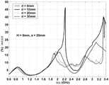
图2是根据本发明的一个实施例(a=20mm)的用于移动设备的天线随d值变化的S参数图;Fig. 2 is an S-parameter diagram of an antenna used for a mobile device according to an embodiment of the present invention (a=20mm) as the d value changes;
图3是根据本发明的一个实施例(a=20mm)的用于移动设备的天线随d值变化的相对带宽图;Fig. 3 is according to an embodiment of the present invention (a=20mm) the relative bandwidth graph that is used for the antenna of mobile equipment as d value changes;
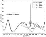
图4是根据本发明的另一个实施例(a=30mm)的用于移动设备的天线随d值变化的S参数图;Fig. 4 is according to another embodiment of the present invention (a=30mm) the S parameter figure that is used for the antenna of mobile equipment as d value changes;
图5是根据本发明的另一个实施例(a=30mm)的用于移动设备的天线随d值变化的相对带宽图;Fig. 5 is according to another embodiment of the present invention (a=30mm) the relative bandwidth graph that is used for the antenna of mobile equipment as d value changes;
图6是根据本发明的再一个实施例(a=40mm)的用于移动设备的天线随d值变化的S参数图;Fig. 6 is the S-parameter diagram of the antenna for mobile equipment according to another embodiment of the present invention (a=40mm) as the d value changes;
图7是根据本发明的再一个实施例(a=40mm)的用于移动设备的天线随d值变化的相对带宽图;Fig. 7 is the relative bandwidth diagram of the antenna for mobile equipment according to another embodiment of the present invention (a=40mm) as d value changes;
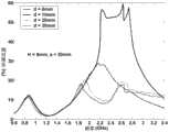
图8是根据本发明的实施例(d=10mm)的用于移动设备的天线随a值变化的S参数图;Fig. 8 is an S-parameter diagram of an antenna for a mobile device varying with a value according to an embodiment of the present invention (d=10mm);
图9是根据本发明的实施例(d=10mm)的用于移动设备的天线随a值变化的相对带宽图;Fig. 9 is a diagram of the relative bandwidth of an antenna for a mobile device according to an embodiment of the present invention (d=10mm) as a function of a value;
图10是根据本发明实施例的用于移动设备的天线的馈电点在其最佳位置(a=30mm,d=10mm)的S参数图(具有匹配电路);Fig. 10 is an S-parameter diagram (with a matching circuit) of the feeding point of the antenna for a mobile device at its optimal position (a=30mm, d=10mm) according to an embodiment of the present invention;
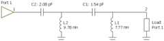
图11是根据本发明实施例的用于移动设备的匹配电路的示意图;11 is a schematic diagram of a matching circuit for a mobile device according to an embodiment of the present invention;
图12是现有的天线的高低端分开形式的双馈电结构示意图。Fig. 12 is a schematic diagram of a double-feed structure in the form of separating high and low ends of an existing antenna.
天线1、
金属外壳10、前侧部101、第一后侧部102、上侧部103、第二后侧部104、下侧部105、缝隙106、单一馈电点107
具体实施方式Detailed ways
下面详细描述本发明的实施例,所述实施例的示例在附图中示出,其中自始至终相同或类似的标号表示相同或类似的元件或具有相同或类似功能的元件。下面通过参考附图描述的实施例是示例性的,仅用于解释本发明,而不能理解为对本发明的限制。Embodiments of the present invention are described in detail below, examples of which are shown in the drawings, wherein the same or similar reference numerals designate the same or similar elements or elements having the same or similar functions throughout. The embodiments described below by referring to the figures are exemplary only for explaining the present invention and should not be construed as limiting the present invention.
在本发明的描述中,需要理解的是,术语“中心”、“纵向”、“横向”、“上”、“下”、“前”、“后”、“左”、“右”、“竖直”、“水平”、“顶”、“底”、“内”、“外”等指示的方位或位置关系为基于附图所示的方位或位置关系,仅是为了便于描述本发明和简化描述,而不是指示或暗示所指的装置或元件必须具有特定的方位、以特定的方位构造和操作,因此不能理解为对本发明的限制。此外,术语“第一”、“第二”仅用于描述目的,而不能理解为指示或暗示相对重要性或者隐含指明所指示的技术特征的数量。由此,限定有“第一”、“第二”的特征可以明示或者隐含地包括一个或者更多个该特征。在本发明的描述中,除非另有说明,“多个”的含义是两个或两个以上。In describing the present invention, it should be understood that the terms "center", "longitudinal", "transverse", "upper", "lower", "front", "rear", "left", "right", " The orientations or positional relationships indicated by "vertical", "horizontal", "top", "bottom", "inner" and "outer" are based on the orientations or positional relationships shown in the drawings, and are only for the convenience of describing the present invention and Simplified descriptions, rather than indicating or implying that the device or element referred to must have a particular orientation, be constructed and operate in a particular orientation, and thus should not be construed as limiting the invention. In addition, the terms "first" and "second" are used for descriptive purposes only, and cannot be interpreted as indicating or implying relative importance or implicitly specifying the quantity of indicated technical features. Thus, a feature defined as "first" and "second" may explicitly or implicitly include one or more of these features. In the description of the present invention, unless otherwise specified, "plurality" means two or more.
在本发明的描述中,需要说明的是,除非另有明确的规定和限定,术语“安装”、“相连”、“连接”应做广义理解,例如,可以是固定连接,也可以是可拆卸连接,或一体地连接;可以是机械连接,也可以是电连接;可以是直接相连,也可以通过中间媒介间接相连,可以是两个元件内部的连通。对于本领域的普通技术人员而言,可以具体情况理解上述术语在本发明中的具体含义。In the description of the present invention, it should be noted that unless otherwise specified and limited, the terms "installation", "connection" and "connection" should be understood in a broad sense, for example, it can be a fixed connection or a detachable connection. Connected, or integrally connected; it can be mechanically connected or electrically connected; it can be directly connected or indirectly connected through an intermediary, and it can be the internal communication of two components. Those of ordinary skill in the art can understand the specific meanings of the above terms in the present invention in specific situations.
下面参考图1描述根据本发明实施例的用于具有金属外壳的移动设备的天线1。如图1所示,所述移动设备具有金属外壳10,天线1由金属外壳10构成。根据本发明实施例的用于移动设备的天线1包括金属外壳10的前侧部101、金属外壳10的上侧部103、金属外壳10的第一后侧部102、金属外壳10的下侧部105和金属外壳10的第二后侧部104。An
第一后侧部102通过金属外壳10的上侧部103与前侧部101相连,第二后侧部104通过金属外壳10的下侧部105与前侧部101相连。其中,第一后侧部102与第二后侧部104通过缝隙106间隔开,缝隙106内设有单一的馈电点107。The first
在大多数情况下,射频前端用于单馈电天线。这里单馈电天线意味着同时用于低频波段和高频波段的普通馈电。如果采用双馈电天线,可以采用以下两种方式:(1)通过重新设计常用的射频前端来直接使用双馈电天线;(2)通过使用天线共用器来将双馈电天线结合到单馈电天线中(在这种情况下,可以依然使用普通的射频前端)。显然,这两种方式都会增加设计的复杂性,因此将限制其应用。另外,在第二种方式中,当使用天线共用器时会使天线系统的损失增加大约0.5dB。In most cases, RF front-ends are used with single-feed antennas. Here single feed antenna means common feed for both low frequency band and high frequency band. If a dual-feed antenna is used, the following two methods can be used: (1) directly use the dual-feed antenna by redesigning the commonly used RF front-end; (2) combine the dual-feed antenna to the single-feed antenna by using an antenna duplexer in an electrical antenna (in this case a normal RF front-end can still be used). Obviously, both of these methods will increase the complexity of the design, thus limiting its application. In addition, in the second way, the loss of the antenna system will increase by about 0.5dB when the antenna duplexer is used.
为了克服以上的缺陷,本发明为具有全金属外壳的移动设备提供了简单且有效的单馈电天线。根据本发明实施例的用于移动设备的天线1通过在第一后侧部102和第二后侧部104之间设置缝隙106(即在金属外壳10的后侧设置缝隙106)且在缝隙106内设置一个单一馈电点107,从而可以使天线1通过单馈电方式更加有效地进行馈电。也就是说,根据本发明实施例的用于利用移动设备的金属外壳作为天线装置1有且只有一个馈电点107,这一个馈电点107在缝隙106内。换言之,对缝隙106做直接的馈电。而且,根据本发明实施例的用于移动设备的天线1可以直接使用支持单馈电天线的普通射频前端,且无需使用天线共用器,从而降低了天线1的设计难度,降低了天线1的制造成本,增加了天线1的可用性。此外,根据本发明实施例的用于移动设备的天线1可以达到更宽的带宽,特别是对于高波段来说。因此,根据本发明实施例的用于移动设备的天线1具有馈电效果好、设计难度低、制造成本低、可用性强、可以达到更宽的带宽。In order to overcome the above drawbacks, the present invention provides a simple and effective single-feed antenna for a mobile device with an all-metal casing. According to the
如图1所示,在本发明的一些实施例中,第一后侧部102在上下方向上的长度a可以是金属外壳10的长度L的1/4。由此可以使天线1在低频波段和高频波段都可以得到更好的相对带宽。其中,上下方向如图1中的箭头A所示。As shown in FIG. 1 , in some embodiments of the present invention, the length a of the first
在本发明的一些示例中,如图1所示,馈电点107与金属外壳10的中心线CL在左右方向上的距离d可以是金属外壳10的宽度W的1/6。由此可以使天线1在低频波段和高频波段都可以得到更好的相对带宽。其中,左右方向如图1中的箭头B所示。In some examples of the present invention, as shown in FIG. 1 , the distance d between the
优选地,当第一后侧部102在上下方向上的长度a为金属外壳10的长度L的1/4且馈电点107与金属外壳10的中心线CL在左右方向上的距离d为金属外壳10的宽度W的1/6时,可以使天线1在低频波段和高频波段都获得最大的带宽。也就是说,馈电点107存在一个最佳的位置(即第一后侧部102在上下方向上的长度a为金属外壳10的长度L的1/4且馈电点107与金属外壳10的中心线CL在左右方向上的距离d为金属外壳10的宽度W的1/6),当馈电点107在其最佳位置时,所获得的天线的带宽将达到最优。Preferably, when the length a of the first
在本发明的一个实施例中,缝隙106在上下方向上的宽度可以是1毫米-3毫米。由此可以使天线1的结构更加合理。有利地,缝隙106在上下方向上的宽度可以是2毫米。In an embodiment of the present invention, the width of the
本发明还提供了一种移动设备。根据本发明实施例的移动设备包括金属外壳10和基于该金属外壳的天线。所述天线为根据上述实施例的用于具有金属外壳的移动设备的天线1。The invention also provides a mobile device. A mobile device according to an embodiment of the present invention includes a
根据本发明实施例的移动设备通过设置根据上述实施例的用于移动设备的天线1,从而具有馈电效果好、设计难度低、制造成本低、可用性强、可以达到更宽的带宽。The mobile device according to the embodiment of the present invention has good feeding effect, low design difficulty, low manufacturing cost, high usability and wider bandwidth by setting the
具体地,所述移动设备可以是移动电话。Specifically, the mobile device may be a mobile phone.
如图1所示,在本发明的一个具体示例中,金属外壳10的长度L可以是100毫米-140毫米,金属外壳10的宽度W可以是40毫米-80毫米,金属外壳10的高度H可以是6毫米-10毫米。As shown in Figure 1, in a specific example of the present invention, the length L of the
图1示出了用于具有金属外壳10的移动设备的单馈电天线,其中金属外壳10几乎覆盖了整个所述移动设备。在金属外壳10的后侧开设有缝隙106,缝隙106将金属外壳10的后侧分隔为第一后侧部102(较小的部分)和第二后侧部104(较大的部分)。金属外壳10可以是所述移动设备的天线1,天线1的馈电位置(馈电点107)可以由参数a(缝隙106的位置)和参数d(与所述移动设备的对称平面的距离)来描述。Figure 1 shows a single-feed antenna for a mobile device with a
天线设计的一个初始目标是达到更宽的带宽。获得更宽的带宽的一种方式是增加/改变天线辐射元件的尺寸(获得更宽的带宽的另外一种方式是使用用于天线的匹配电路)。对于以金属外壳10形式存在的天线1,金属外壳10的外围尺寸是预先设计好的,因此不能再改变。但是即使是在金属外壳的外围尺寸不能再改变时,该天线的馈电位置决定该天线的带宽,也就是说,该天线存在最佳的馈电位置,具体描述如下。An initial goal of antenna design is to achieve wider bandwidth. One way to get wider bandwidth is to increase/change the size of the antenna's radiating element (another way to get wider bandwidth is to use a matching circuit for the antenna). For the
对于天线来说,获得理想的带宽的可能性取决于它能达到的相对带宽或带宽潜力。相对带宽或带宽潜力越大,天线通过匹配电路达到的带宽越宽。天线可以达到的相对带宽受到很多参数的影响,例如天线尺寸和馈电位置。为了减小天线设计周期,在设计匹配电路前最好能够了解天线的相对带宽或带宽潜力。For an antenna, the probability of obtaining the desired bandwidth depends on its relative bandwidth or bandwidth potential. The greater the relative bandwidth or bandwidth potential, the wider the bandwidth achieved by the antenna through the matching circuit. The relative bandwidth achievable by an antenna is influenced by many parameters such as antenna size and feed location. In order to reduce the antenna design cycle, it is best to know the relative bandwidth or bandwidth potential of the antenna before designing the matching circuit.
作为一个例子以金属外壳具有下面的尺寸为例说明如何选择最佳馈电位置:金属外壳10的外围长度L=120毫米,外围宽度W=60毫米,外围高度H=8毫米,缝隙106在上下方向上的宽度为2毫米。如上所述,馈电位置可以通过参数a和参数d来进行描述。As an example, take the following dimensions of the metal casing as an example to illustrate how to select the best feed position: the peripheral length L=120 mm of the
图2为根据本发明实施例的用于移动设备的天线1的S参数图(参数a=20毫米,参数d为变量),图3为根据本发明实施例的用于移动设备的天线1的相对带宽图(参数a=20毫米,参数d为变量)。图4为根据本发明实施例的用于移动设备的天线1的S参数图(参数a=30毫米,参数d为变量),图5为根据本发明实施例的用于移动设备的天线1的相对带宽图(参数a=30毫米,参数d为变量)。图6为根据本发明实施例的用于移动设备的天线1的S参数图(参数a=40毫米,参数d为变量),图7为根据本发明实施例的用于移动设备的天线1的相对带宽图(参数a=40毫米,参数d为变量)。Fig. 2 is an S-parameter diagram (parameter a = 20 mm, parameter d is a variable) of an
由图2-图7可以看出,对于不同数值的参数a(20毫米、30毫米、40毫米),当参数d=10毫米时,天线1在低频波段和高频波段可以获得更好的相对带宽。It can be seen from Figure 2-7 that for different values of parameter a (20 mm, 30 mm, 40 mm), when parameter d=10 mm,
图8为根据本发明实施例的用于移动设备的天线1的S参数图(参数d=10毫米,参数a为变量),图9为根据本发明实施例的用于移动设备的天线1的相对带宽图(参数d=10毫米,参数a为变量)。由图8和图9可以看出:尽管参数a越大,天线1在低频波段可以获得更好的相对带宽,但是当参数a=30毫米时,天线1在低频波段和高频波段可以同时获得较好的相对带宽;能同时对低频波段和高频波段获得较好的带宽的馈电位置为馈电点的最佳位置。Fig. 8 is an S-parameter diagram of an
图2-图9中显示的结果表明,当金属外壳10的外围尺寸固定在长度L=120毫米,宽度W=60毫米,高度H=8毫米时,当参数a=30毫米且参数d=10毫米时,可以得到最佳的馈电位置。The results shown in Figures 2-9 show that when the outer dimensions of the
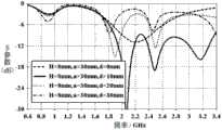
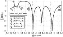
图10为具有匹配电路时根据本发明实施例的用于移动设备的天线1的S参数图(参数a=30毫米,参数d=10毫米),其中匹配电路如图11所示。由图10可以看出,天线1在-6dB水平的回波损失覆盖了频率为795MHz–987MHz的低频波段(覆盖GSM850/900)和频率为1705MHz–3305MHz的高频波段(覆盖GSM1800/1900、WCDMA2100和LTE2300/2500)。FIG. 10 is an S-parameter diagram (parameter a=30mm, parameter d=10mm) of the
事实上,通过缝隙106贡献的谐振可以在高频波段获得更宽的带宽,缝隙106贡献的谐振由缝隙106内的馈电位置控制。与现有的双馈电天线相比,这可以被视为是一个优势。另外,与现有的双馈电天线类似,低频波段主要靠金属外壳10的第二后侧部104贡献,而高频波段主要靠金属外壳10的第一后侧部102贡献。In fact, a wider bandwidth can be obtained in the high frequency band through the resonance contributed by the
在本说明书的描述中,参考术语“一个实施例”、“一些实施例”、“示意性实施例”、“示例”、“具体示例”、或“一些示例”等的描述意指结合该实施例或示例描述的具体特征、结构、材料或者特点包含于本发明的至少一个实施例或示例中。在本说明书中,对上述术语的示意性表述不一定指的是相同的实施例或示例。而且,描述的具体特征、结构、材料或者特点可以在任何的一个或多个实施例或示例中以合适的方式结合。In the description of this specification, references to the terms "one embodiment," "some embodiments," "exemplary embodiments," "example," "specific examples," or "some examples" are intended to mean that the implementation A specific feature, structure, material, or characteristic described by an embodiment or example is included in at least one embodiment or example of the present invention. In this specification, schematic representations of the above terms do not necessarily refer to the same embodiment or example. Furthermore, the specific features, structures, materials or characteristics described may be combined in any suitable manner in any one or more embodiments or examples.
尽管已经示出和描述了本发明的实施例,本领域的普通技术人员可以理解:在不脱离本发明的原理和宗旨的情况下可以对这些实施例进行多种变化、修改、替换和变型,本发明的范围由权利要求及其等同物限定。Although the embodiments of the present invention have been shown and described, those skilled in the art can understand that various changes, modifications, substitutions and modifications can be made to these embodiments without departing from the principle and spirit of the present invention. The scope of the invention is defined by the claims and their equivalents.
Claims (8)
Translated fromChinesePriority Applications (1)
| Application Number | Priority Date | Filing Date | Title |
|---|---|---|---|
| CN201310701625.6ACN103700936B (en) | 2013-12-18 | 2013-12-18 | For having the antenna of metal shell mobile device and relative mobile device |
Applications Claiming Priority (1)
| Application Number | Priority Date | Filing Date | Title |
|---|---|---|---|
| CN201310701625.6ACN103700936B (en) | 2013-12-18 | 2013-12-18 | For having the antenna of metal shell mobile device and relative mobile device |
Publications (2)
| Publication Number | Publication Date |
|---|---|
| CN103700936Atrue CN103700936A (en) | 2014-04-02 |
| CN103700936B CN103700936B (en) | 2016-08-31 |
Family
ID=50362388
Family Applications (1)
| Application Number | Title | Priority Date | Filing Date |
|---|---|---|---|
| CN201310701625.6AExpired - Fee RelatedCN103700936B (en) | 2013-12-18 | 2013-12-18 | For having the antenna of metal shell mobile device and relative mobile device |
Country Status (1)
| Country | Link |
|---|---|
| CN (1) | CN103700936B (en) |
Cited By (6)
| Publication number | Priority date | Publication date | Assignee | Title |
|---|---|---|---|---|
| CN105006644A (en)* | 2014-04-16 | 2015-10-28 | 广达电脑股份有限公司 | Mobile communication device |
| CN105244598A (en)* | 2015-10-30 | 2016-01-13 | 维沃移动通信有限公司 | Antenna system and mobile terminal |
| CN105305067A (en)* | 2015-10-29 | 2016-02-03 | 维沃移动通信有限公司 | Antenna system and mobile terminal |
| WO2017133064A1 (en)* | 2016-02-02 | 2017-08-10 | 上海德门电子科技有限公司 | Metal housing-based near field communication apparatus, electronic device, and method |
| WO2018232842A1 (en)* | 2017-06-23 | 2018-12-27 | 深圳市大疆创新科技有限公司 | Yuntai |
| US10770797B2 (en) | 2017-04-18 | 2020-09-08 | Asustek Computer Inc. | Antenna element |
Citations (6)
| Publication number | Priority date | Publication date | Assignee | Title |
|---|---|---|---|---|
| JP2002064320A (en)* | 2000-08-21 | 2002-02-28 | Furukawa Electric Co Ltd:The | Wireless terminal |
| WO2002063713A2 (en)* | 2000-10-27 | 2002-08-15 | Telefonaktiebolaget L.M. Ericsson (Publ) | Notch antennas and wireless communicators incorporating same |
| CN1595718A (en)* | 2003-09-09 | 2005-03-16 | 索尼株式会社 | Wireless communication apparatus |
| CN101800361A (en)* | 2010-03-23 | 2010-08-11 | 中兴通讯股份有限公司 | Wireless device |
| CN102195131A (en)* | 2010-02-02 | 2011-09-21 | 莱尔德技术股份有限公司 | An antenna device for a radio communication device |
| EP2528165A1 (en)* | 2011-05-27 | 2012-11-28 | Apple Inc. | Dynamically adjustable antenna supporting multiple antenna modes |
- 2013
- 2013-12-18CNCN201310701625.6Apatent/CN103700936B/ennot_activeExpired - Fee Related
Patent Citations (6)
| Publication number | Priority date | Publication date | Assignee | Title |
|---|---|---|---|---|
| JP2002064320A (en)* | 2000-08-21 | 2002-02-28 | Furukawa Electric Co Ltd:The | Wireless terminal |
| WO2002063713A2 (en)* | 2000-10-27 | 2002-08-15 | Telefonaktiebolaget L.M. Ericsson (Publ) | Notch antennas and wireless communicators incorporating same |
| CN1595718A (en)* | 2003-09-09 | 2005-03-16 | 索尼株式会社 | Wireless communication apparatus |
| CN102195131A (en)* | 2010-02-02 | 2011-09-21 | 莱尔德技术股份有限公司 | An antenna device for a radio communication device |
| CN101800361A (en)* | 2010-03-23 | 2010-08-11 | 中兴通讯股份有限公司 | Wireless device |
| EP2528165A1 (en)* | 2011-05-27 | 2012-11-28 | Apple Inc. | Dynamically adjustable antenna supporting multiple antenna modes |
Cited By (6)
| Publication number | Priority date | Publication date | Assignee | Title |
|---|---|---|---|---|
| CN105006644A (en)* | 2014-04-16 | 2015-10-28 | 广达电脑股份有限公司 | Mobile communication device |
| CN105305067A (en)* | 2015-10-29 | 2016-02-03 | 维沃移动通信有限公司 | Antenna system and mobile terminal |
| CN105244598A (en)* | 2015-10-30 | 2016-01-13 | 维沃移动通信有限公司 | Antenna system and mobile terminal |
| WO2017133064A1 (en)* | 2016-02-02 | 2017-08-10 | 上海德门电子科技有限公司 | Metal housing-based near field communication apparatus, electronic device, and method |
| US10770797B2 (en) | 2017-04-18 | 2020-09-08 | Asustek Computer Inc. | Antenna element |
| WO2018232842A1 (en)* | 2017-06-23 | 2018-12-27 | 深圳市大疆创新科技有限公司 | Yuntai |
Also Published As
| Publication number | Publication date |
|---|---|
| CN103700936B (en) | 2016-08-31 |
Similar Documents
| Publication | Publication Date | Title |
|---|---|---|
| CN103700936B (en) | For having the antenna of metal shell mobile device and relative mobile device | |
| TWI624999B (en) | Atnenna structure and wireless communiation device employing same | |
| TWI556506B (en) | Mobile device | |
| TWI608658B (en) | Antenna structure and wireless communication device using same | |
| CN107681249B (en) | Antenna structure and wireless communication device with same | |
| US10069199B2 (en) | Antenna and radio frequency signal transceiving device | |
| WO2019090690A1 (en) | Antenna of mobile terminal and mobile terminal | |
| TWI434458B (en) | Multi - frequency antenna module | |
| CN105742812A (en) | Mobile terminal and antenna structure thereof | |
| EP2493011A1 (en) | Mobile communication device and antenna structure therein | |
| TWI599095B (en) | Antenna structure and wireless communication device using the same | |
| EP3220478B1 (en) | Diversity antenna | |
| CN104993241A (en) | Mobile terminal and antenna device thereof | |
| JP2014533474A (en) | Multi-mode broadband antenna module and wireless terminal | |
| CN106816688B (en) | Antenna and mobile terminal having the same | |
| CN105098354A (en) | Mobile terminal and antenna device | |
| JP5742426B2 (en) | Plate-shaped inverted F antenna | |
| JP2017530614A (en) | Decoupling antenna for wireless communication | |
| JP6272505B2 (en) | Antenna device and terminal | |
| CN104953290B (en) | Wireless telecommunications system and its antenna assembly | |
| TWI581499B (en) | Antenna assembly | |
| CN211350957U (en) | Antenna and mobile terminal having the same | |
| US8896494B2 (en) | Hanging type monopole wideband antenna | |
| CN106785432A (en) | Antenna device for mobile terminal and mobile terminal | |
| KR102586064B1 (en) | Antenna apparatus |
Legal Events
| Date | Code | Title | Description |
|---|---|---|---|
| C06 | Publication | ||
| PB01 | Publication | ||
| C10 | Entry into substantive examination | ||
| SE01 | Entry into force of request for substantive examination | ||
| C14 | Grant of patent or utility model | ||
| GR01 | Patent grant | ||
| CF01 | Termination of patent right due to non-payment of annual fee | ||
| CF01 | Termination of patent right due to non-payment of annual fee | Granted publication date:20160831 |